Embed Size (px)
Citation preview

Geometric Rectification of Camera-CapturedDocument Images
Jian Liang, Member, IEEE, Daniel DeMenthon, Member, IEEE, and David Doermann, Member, IEEE
Abstract—Compared to typical scanners, handheld cameras offer convenient, flexible, portable, and noncontact image capture, which
enables many new applications and breathes new life into existing ones. However, camera-captured documents may suffer from
distortions caused by a nonplanar document shape and perspective projection, which lead to the failure of current optical character
recognition (OCR) technologies. We present a geometric rectification framework for restoring the frontal-flat view of a document from a
single camera-captured image. Our approach estimates the 3D document shape from texture flow information obtained directly from the
image without requiring additional 3D/metric data or prior camera calibration. Our framework provides a unified solution for both planar
and curved documents and can be applied in many, especially mobile, camera-based document analysis applications. Experiments
show that our method produces results that are significantly more OCR compatible than the original images.
Index Terms—Camera-based OCR, image rectification, shape estimation, texture flow analysis.
Ç
1 INTRODUCTION
RECENT technical advances in digital cameras have led theoptical character recognition (OCR) community to
consider using them instead of scanners for documentcapture [1]. First, cameras are portable, long-range, andnoncontact imaging devices that enable many new docu-ment analysis applications. Second, cameras can be easilyintegrated with portable computing devices such as PDAs,cell phones, and media players. Last, many more digitalcameras are manufactured, distributed, and owned thanscanners. Together, these factors contribute to the growinginterest in camera-based document analysis.
For example, handheld devices equipped with cameras,such as PDAs and cell phones, are ideal platforms formobile OCR applications such as the recognition of streetsigns in foreign languages, out-of-office digitization ofdocuments, and text-to-voice input for the visually im-paired. In the industrial market, high-end cameras havebeen used for digitizing thick books and fragile historicmanuscripts unsuitable for scanning; in the consumermarket, camera-based document capture is utilized in thedesktop environment [2].
The challenge in camera-based applications is that due tothe differences between scanners and cameras, traditionalscanner-oriented OCR techniques are usually not applicable.In particular, nonplanar document shape and perspective
projection, which are common in camera-captured images,are not expected at all by traditional OCR algorithms. As aresult, the performance of some of the state-of-the-art OCRpackages on camera-captured documents is unacceptable.
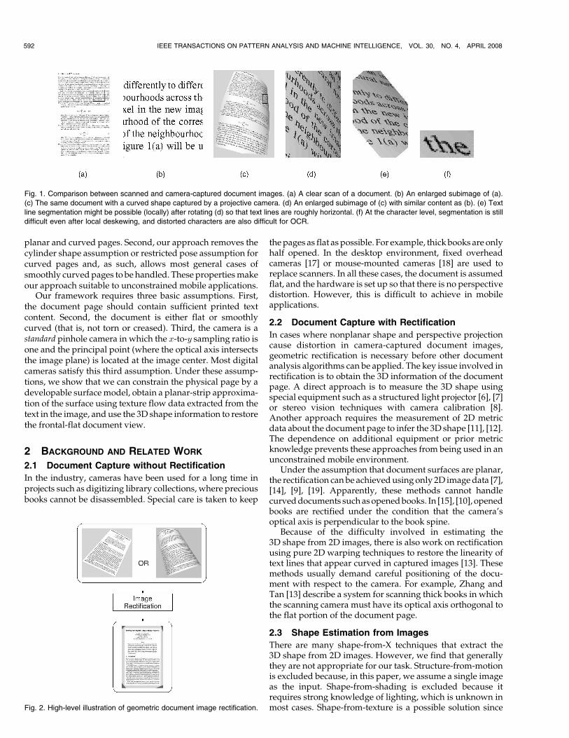
For instance, Fig. 1 compares a clean scan to a syntheticcamera image. First, curved text lines and margins in Fig. 1ccan easily defeat most page segmentation techniques (forexample, [3], [4], [5]). Second, skewed characters make bothsegmentation and recognition difficult. To a lesser degree,these challenges also apply to planar pages. Our experimentsshow that the OCR performance on camera-captured docu-ments, whether planar or curved, is substantially lower thanfor scanned images. Since we use noise-free, blur-free, andhigh-resolution images in these experiments, the influence ofother effects is reduced to the minimum, which proves that apure 2D image enhancement will not be helpful.
The key problem in document image rectification is toobtain the 3D shape of the page. In the literature, there havebeen three major approaches. The first assumes explicit3D range data obtained through special equipments [6], [7],[8], the second approach simplifies the problem byassuming flat pages [9], [7], and the third approach assumesa restricted shape and pose of the page [10] or additionalmetric information of markings on the page [11], [12]. Thereare also methods that only rely on 2D warping techniques[13]. However, because of the lack of 3D information, suchmethods are restricted to flat pages with small perspectivedistortion (see discussion in Section 3.2.1).
In this paper, we present a rectification framework thatextracts the 3D document shape from a single 2D image andperforms a shape-based geometric rectification to restore thefrontal-flat view of the document. Fig. 2 illustrates the systemlevel concept of our framework. The output image iscomparable to scanned images and is significantly moreOCR compatible than the input. Compared to previousapproaches, our method does not need additional 3D/metricdata, prior camera calibration, or special restrictions on thedocument shape and pose. Our method borrows insightsfrom previous work ([14], [9], [15], [16], [13]). One of ourcontributions is that our framework unifies the processing of
IEEE TRANSACTIONS ON PATTERN ANALYSIS AND MACHINE INTELLIGENCE, VOL. 30, NO. 4, APRIL 2008 591
. J. Liang is with Amazon.com, 701 5th Ave. #614.B, Seattle, WA 98104.E-mail: [email protected].
. D. DeMenthon is with the Institute for Advanced Computer Studies,University of Maryland, 3449 AV Williams Building, College Park, MD20742. E-mail: [email protected].
. D. Doermann is with the Laboratory for Language and Media Processing,Institute for Advanced Computer Studies, University of Maryland, 3451AV Williams Building, College Park, MD 20742.E-mail: [email protected].
Manuscript received 2 July 2006; revised 6 Feb. 2007; accepted 8 May 2007;published online 13 June 2007.Recommended for acceptance by K. Kutulakos.For information on obtaining reprints of this article, please send e-mail to:[email protected], and reference IEEECS Log Number TPAMI-0485-0706.Digital Object Identifier no. 10.1109/TPAMI.2007.70724.
0162-8828/08/$25.00 � 2008 IEEE Published by the IEEE Computer Society
planar and curved pages. Second, our approach removes thecylinder shape assumption or restricted pose assumption forcurved pages and, as such, allows most general cases ofsmoothly curved pages to be handled. These properties makeour approach suitable to unconstrained mobile applications.
Our framework requires three basic assumptions. First,the document page should contain sufficient printed textcontent. Second, the document is either flat or smoothlycurved (that is, not torn or creased). Third, the camera is astandard pinhole camera in which the x-to-y sampling ratio isone and the principal point (where the optical axis intersectsthe image plane) is located at the image center. Most digitalcameras satisfy this third assumption. Under these assump-tions, we show that we can constrain the physical page by adevelopable surface model, obtain a planar-strip approxima-tion of the surface using texture flow data extracted from thetext in the image, and use the 3D shape information to restorethe frontal-flat document view.
2 BACKGROUND AND RELATED WORK
2.1 Document Capture without Rectification
In the industry, cameras have been used for a long time inprojects such as digitizing library collections, where preciousbooks cannot be disassembled. Special care is taken to keep
the pages as flat as possible. For example, thick books are onlyhalf opened. In the desktop environment, fixed overheadcameras [17] or mouse-mounted cameras [18] are used toreplace scanners. In all these cases, the document is assumedflat, and the hardware is set up so that there is no perspectivedistortion. However, this is difficult to achieve in mobileapplications.
2.2 Document Capture with Rectification
In cases where nonplanar shape and perspective projectioncause distortion in camera-captured document images,geometric rectification is necessary before other documentanalysis algorithms can be applied. The key issue involved inrectification is to obtain the 3D information of the documentpage. A direct approach is to measure the 3D shape usingspecial equipment such as a structured light projector [6], [7]or stereo vision techniques with camera calibration [8].Another approach requires the measurement of 2D metricdata about the document page to infer the 3D shape [11], [12].The dependence on additional equipment or prior metricknowledge prevents these approaches from being used in anunconstrained mobile environment.
Under the assumption that document surfaces are planar,the rectification can be achieved using only 2D image data [7],[14], [9], [19]. Apparently, these methods cannot handlecurved documents such as opened books. In [15], [10], openedbooks are rectified under the condition that the camera’soptical axis is perpendicular to the book spine.
Because of the difficulty involved in estimating the3D shape from 2D images, there is also work on rectificationusing pure 2D warping techniques to restore the linearity oftext lines that appear curved in captured images [13]. Thesemethods usually demand careful positioning of the docu-ment with respect to the camera. For example, Zhang andTan [13] describe a system for scanning thick books in whichthe scanning camera must have its optical axis orthogonal tothe flat portion of the document page.
2.3 Shape Estimation from Images
There are many shape-from-X techniques that extract the3D shape from 2D images. However, we find that generallythey are not appropriate for our task. Structure-from-motionis excluded because, in this paper, we assume a single imageas the input. Shape-from-shading is excluded because itrequires strong knowledge of lighting, which is unknown inmost cases. Shape-from-texture is a possible solution since
592 IEEE TRANSACTIONS ON PATTERN ANALYSIS AND MACHINE INTELLIGENCE, VOL. 30, NO. 4, APRIL 2008
Fig. 1. Comparison between scanned and camera-captured document images. (a) A clear scan of a document. (b) An enlarged subimage of (a).
(c) The same document with a curved shape captured by a projective camera. (d) An enlarged subimage of (c) with similar content as (b). (e) Text
line segmentation might be possible (locally) after rotating (d) so that text lines are roughly horizontal. (f) At the character level, segmentation is still
difficult even after local deskewing, and distorted characters are also difficult for OCR.
Fig. 2. High-level illustration of geometric document image rectification.

printed text presents a regular pattern. However, a traditionaltexture gradient analysis ([20], [21]) may be less accurate withdocument images since it is difficult to define textons in text.Shape-from-contour utilizes the symmetry or other metricinformation of 2D contours on the surface. In practice, metricdata is usually absent, whereas symmetry is vulnerable toocclusion. Therefore, in general, most shape-from-X techni-ques can provide a rough qualitative shape estimation but notaccurate quantitative data to support the rectification ofdocument images.
2.4 Physical Modeling of Curved Documents
The shape of a curved document belongs to a family of2D surfaces called developable surfaces, as long as thedocument is not torn, creased, or deformed by a soak-and-dry process. In mathematical terms, developable surfaces are2D manifolds that can be isometrically mapped to a euclideanplane. In other words, developable surfaces can unroll to aplane without tearing or stretching. This developing processpreserves intrinsic surface properties such as the arc lengthand the angle between lines on the surface.
The developable surface model is used in [7], [6], [8] to fitthe 3D range data of a curved document. In our work, wedo not assume a priori 3D data. Instead, we use thedevelopable-surface model to constrain the 3D shapeestimation process.
2.5 Texture Flow and Shape Perception
Psychological observations suggest that a texture pattern thatexhibits local parallelism gives a viewer the perception of acontinuous flow field [22], [23], which we call a texture flowfield. A typical example is the pattern of a zebra’s stripes.Through a projection process (performed by a camera or ahuman visual system), a 3D flow field projects to a 2D field onthe image plane. Under some mild assumptions, 2D flowfields effectively reveal the underlying 3D surface shape [24].
In documents, there are two important clues that a humanvisual system can use to infer the shape. First, documentpages form developable surfaces. Second, there exist twowell-defined texture flow fields representing local text lineand vertical character stroke directions, respectively. On a flatdocument, the two fields are individually parallel andmutually orthogonal everywhere. This property is preservedlocally for curved documents under the developable surfacemodel. Therefore, a human visual system can quickly graspthe local surface orientations using the texture flow fields andintegrate them using the global surface model to obtain depthperception.
3 APPROACH
3.1 Overview
We propose a framework that rectifies the image of agenerally curved document, from the analysis of a pageshape model and texture flow properties. It requires thatthere is sufficient text in the view. Our workflow beginswith detecting the text area and the texture flow fields(Section 3.2.1) and then distinguishes planar and curvedpages by verifying the linearity property of texture flowfields (Section 3.2.2). Next, it uses geometric properties ofplanar surfaces (Section 3.3) or curved developable surfacesto estimate the 3D shape of the page (Section 3.4), and last, ituses the 3D shape to unwarp the image. The output imageis a frontal view of the flat page, just as from a scan.
3.2 Preprocessing
3.2.1 Two-Dimensional Texture Flow Detection in
Document Images
The first step in our processing is text identification, whichlocates the text area in the image and binarizes the text. Ouralgorithm is a gradient-based method [25]. Text identificationis a difficult problem in itself, deserving further research [1].Therefore, we do not address its details in this paper.
After text is found, we detect the local text line andvertical character stroke directions, which we define as themajor and minor texture flows, respectively.
We formulate the major texture flow detection as a localskew detection problem. In document image analysis, skewdetection finds the orientation of text lines with respect tothe horizontal axis. In scanned documents, there is typicallyone global skew angle for the entire page. In camera-captured curved documents, the local skew angle variesacross the entire image. Nevertheless, locally, it is roughlyconsistent. We apply the classic projection profile analysis[26] to detect the skew angle in a small neighborhood. Then,we use a relaxation labeling approach [27] to smooth outpossible errors and obtain a coherent result [25].
We use directional filters to extract the linear structuresof characters [28]. Vertical strokes are very common in text;thus, the response of the filter usually exhibits a maximumwhen the filter’s direction aligns with vertical strokes.Horizontal strokes also result in a maximum, but it can bedetected and removed by comparing its direction to themajor texture flow.
Fig. 3 shows estimated texture flows in real images. Notethat in Fig. 3b, the minor texture flow lines are straight andaligned with the cylinder generatrix, whereas in Fig. 3c, bothtexture flow lines are curved, which represents the most
LIANG ET AL.: GEOMETRIC RECTIFICATION OF CAMERA-CAPTURED DOCUMENT IMAGES 593
Fig. 3. Texture flow results on real images. (a) A planar page. (b) An open book with a cylindrical shape. (c) A page with a noncylindrical shape.

general case. The synthetic image in Fig. 1c belongs to thelatter case. For such cases, skipping 3D structure computationand using texture flows alone to rectify the images by2D warping would result in an incorrect output. The rest ofthis paper describes our method of extracting a 3D structurefrom texture flows and using it to process general curveddocument images. Nevertheless, in Section 5, we discusssimplifications for constrained cases (for example, Fig. 3b).
3.2.2 Surface Classification
Perspective projection preserves linearity, so straight textlines on planar documents remain straight in camera-captured images. Furthermore, these coplanar and parallel3D lines share a common vanishing point in the image [29].These two properties do not hold true for curved text lines oncurved documents. Under perspective projection, althoughone curve lying on a plane of sight (a plane passing through theoptical center) has a straight line as its projection in the image,multiple text lines on a curved document surface cannotsimultaneously satisfy this requirement. Their projectionscannot converge at a single point either. Therefore, we candetermine whether the document is planar or curved bytesting the linearity and convergence of text lines, which, inour case, can be verified using the major texture flow field.The minor texture flow field can be used too.
Let flig be a set of texture flow tangent lines (lines in thedirection of the texture flow passing through any point)represented with the formalism of projective geometry.Under the planar page hypothesis, all these flow tangentlines flig converge at a vanishing point, say, v (inhomogeneous representation too), which can be written as
l>i v ¼ 0; 8i:
This means that v lies in the null space of the subspacespanned by flig; in other words, the rank of L ¼ ðl1; . . . ; lNÞis less than three. By contrast, under the curved documenthypothesis, v does not exist, which means that the nullspace of L is ;, and L has full rank.
We use SVD decomposition to compute the eigenvaluesof L. Let S1 and S3 be the largest and smallest eigenvalues,respectively. We use S3=S1 as the convergence qualitymeasure. If it rests below a predefined threshold, we decidethat L does not have full rank.
3.3 Rectification of Planar Documents
This section covers the rectification of planar documentimages. From projective geometry, we know that thehomography depends on the plane orientation N andcamera focal length f . Together, they determine the positionof the plane in the camera’s coordinate system. In thefollowing, we first deduce N and f from texture flow fields.Then, we construct the homography and show that in theend, N and f do not need to be explicitly sought. AlthoughN and f do not show up in the final formula, their estimatescan help us to benchmark the precision of our method.
3.3.1 Page Plane Estimation
From the surface classification step described in the previoussection, we obtain vh and vv, the vanishing points of the majorand minor texture flow tangent lines. As [30] shows, a fullmetric rectification for a general projective transformationhas five degrees of freedom. The line l1 connecting vh and vvis the vanishing line of the world plane, which involves two
degrees of freedom and reduces the projective transformationto an affine transformation. The positions of the vanishingpoints in the world plane (the infinity points at north and east)allow us to remove the shearing and rotation from the affinetransformation. This leaves us with an unknownx-to-y aspectratio,1 which cannot be determined using only the twovanishing points (see Fig. 4).
It is shown in [30] that additional metric data such as a
length ratio or an angle (other than the right angle between
the two texture flows) on the world plane can help solve for
the last degree of freedom. We take a different approach; we
assume that the principal point rests at the image center.
This is usually true unless the image is cropped. Under this
assumption, suppose that the two vanishing points are vh ¼ðxh; yhÞ> and vv ¼ ðxv; yvÞ>. Then, the 3D directions of the
major and minor texture flows in the camera coordinate
system are given by
Vh ¼ðv>h ; fÞ>;
Vv ¼ðv>v ; fÞ>;
ð1Þ
where f is the focal length. Due to their orthogonality in the3D plane, that is,
V>hVv ¼ 0 ð2Þ
it follows that
f ¼ffiffiffiffiffiffiffiffiffiffiffiffiffiffiffi�v>h vv
q¼
ffiffiffiffiffiffiffiffiffiffiffiffiffiffiffiffiffiffiffiffiffiffiffiffiffiffiffiffiffiffiffiffi�ðxhxv þ yhyvÞ
pð3Þ
if v>h vv < 0. When f is known, the plane normal N is also
fixed by
N ¼ ðVh �VvÞ=jVh �Vvj:
Special care should be taken when either vh or vv lies at the
infinity of the image plane. When a vanishing point lies at
infinity, say,vh, thenthez-componentofVh is zero, regardless
of f . Therefore, (2) does not involve the focal length, and we
cannot solve for it. If both vanishing points lie at infinity, the
document is simply parallel to the image plane, and there is no
perspective distortion. We need only rotate the image such
that the two vanishing points map to the east and north. If only
one vanishing point is at infinity, there is foreshortening along
the direction of the other vanishing point. In this case, we are
594 IEEE TRANSACTIONS ON PATTERN ANALYSIS AND MACHINE INTELLIGENCE, VOL. 30, NO. 4, APRIL 2008
1. This is different from the x-to-y sampling ratio in the camera model,which we assume to be one.
Fig. 4. Nonunique image rectification results. (a) A perspective-distorted
image. (b) and (c) are two possible rectification results that have
different x-to-y aspect ratios. Both (b) and (c) are OCR compatible.

back to the situation where we can remove the perspective
distortion up to an unknown aspect ratio.When either vh or vv lies near the infinity, due to the
noise in texture flow detection, we may arrive at vanishing-point positions that are theoretically impossible. It could bethat v>h vv > 0; or at least one vanishing point lies at theinfinity, but the directions of the two vanishing points arenot orthogonal.
Note that these cases where we cannot solve for f
happen most often when the camera’s optical axis is nearlyperpendicular to the document. In such cases, the rectifica-tion homography is underdetermined. Fortunately, for suchcamera configurations, the error introduced by the un-certainty in the rectification homography is small.
3.3.2 Metric Rectification
When perspective foreshortening is strong and rectificationis most needed, we can compute f and N and then computethe full metric homography in the following way.
Consider an arbitrary point ðx0; y0Þ in the image plane. Inthe camera’s 3D coordinate system, its position is ðx0; y0; fÞ>.It follows that the corresponding 3D point located in the planeof the document is W ¼ dðx0; y0; fÞ>, where d ð> 0Þ is anunknown depth factor. Define unit vectors Vh ¼ Vh=jVhjand Vv ¼ Vv=jVvj. Suppose that we set up a 2D coordinatesystem in the document plane so that the x-axis is alignedwith Vh, whereas the y-axis is (must be) aligned with Vv.Every point on the document plane thus has a 2D coordinate.Assume that W has coordinate ðx00; y00Þ on the page. Then, the3D position of any point ðx0; y0Þ on the page is
P ¼ðx0 � x00ÞVh þ ðy0 � y00ÞVv þW
¼�
Vh Vv W
� 1 0 �x000 1 �y000 0 1
0B@
1CA
x0
y0
1
0B@
1CA:
A general projective camera model can be parameter-ized by a 3� 3 upper triangular matrix K [29]. Mostdigital cameras have unit x-to-y ratio and zero shear. Also,the principal point offset is typically zero. Therefore, thematrix K simplifies to
K ¼f 0 00 f 00 0 1
0@
1A;
where f is the focal length. A 3D point P ¼ ðX;Y ; ZÞ> in thecamera’s coordinate system projects to a point ðx; yÞ in theimage by
uvw
0@
1A ¼ K
XYZ
0@
1A; ð4Þ
where x ¼ u=w, and y ¼ v=w.Overall, the homogeneous transformation from docu-
ment plane to image plane is the concatenation
H ¼ K
�Vh Vv W
� 1 0 �x000 1 �y000 0 1
0@
1A: ð5Þ
The inverse of H maps every point in the image planeback to the frontal-flat view of the document page and iscalled the rectification matrix. That is,
ðx; yÞ !H�1
ðx0; y0Þ: ð6Þ
In (5), d and ðx00; y00Þ can take any value. The value ofðx00; y00Þ determines the translation of the rectified imagewithin the destination plane. This translation cannot bederived from the image itself, nor is it relevant from theviewpoint of rectification. The depth factor d determines thescale of the rectified image—the larger the depth, the largerthe rectified image. Similarly, this depth factor cannot bedetermined using only the image. Additional metricinformation must be known to fix d.
In our implementation, we choose d ¼ 1, ðx0; y0Þ ¼ ð0; 0Þ,and ðx00; y00Þ ¼ ð0; 0Þ. Therefore, W ¼ ð0; 0; fÞ>. Let vh ¼ðxh; yhÞ> and vv ¼ ðxv; yvÞ>. Moreover, let
� ¼ 1=jVhj ¼ 1=ffiffiffiffiffiffiffiffiffiffiffiffiffiffiffiffiffiffiffiffiffiffiffiffiffiffiffiffiffiffiffiffiffiffiffiffiffiffiffiffiffiffiffiffiffiffiffiffiffix2h þ y2
h � ðxhxv þ yhyvÞq
;
� ¼ 1=jVvj ¼ 1=ffiffiffiffiffiffiffiffiffiffiffiffiffiffiffiffiffiffiffiffiffiffiffiffiffiffiffiffiffiffiffiffiffiffiffiffiffiffiffiffiffiffiffiffiffiffiffiffiffix2v þ y2
v � ðxhxv þ yhyvÞq
;
where we replaced f by its expression found in (3). Then,(5) becomes
H ¼f 0 0
0 f 0
0 0 1
0B@
1CA
�xh �xv 0
�yh �yv 0
�f �f f
0B@
1CA
¼ f�xh �xv 0
�yh �yv 0
� � 1
0B@
1CA:
ð7Þ
Computing the inverse of H allows us to compute thecomponent x0 and y0 of the rectification mapping describedby (6)
x0 ¼� yvx� xvyðyh � yvÞxþ ðxv � xhÞyþ ðxhyv � xvyhÞ
;
y0 ¼� xhy� yhxðyh � yvÞxþ ðxv � xhÞyþ ðxhyv � xvyhÞ
;
ð8Þ
which maps a point ðx; yÞ in the input image to the pointðx0; y0Þ in the rectified image. Since f and N do not appear in(8), we can rectify a planar document even if they are notavailable because of the reasons discussed in the previoussection. In those cases, the metric rectification is partial.
Because we cannot determine from texture flow analysisalone whether Vh points toward the left or right of the flatdocument and whether Vv points toward the top or bottom,the rectified image may end up being flipped vertically,horizontally, or both. In the last case, the page is simplyrotated by 180 degrees, as if it was scanned upside down.There is no simple way to tell that a document is upside down(sophisticated training-based methods do exist [31]). Theflipping in the first two cases can be removed easily though.We take any three noncollinear points in the input image andrecord their clockwise order. In the output image, we findtheir clockwise order too. If the two orders are different, thenwe flip the image vertically (or horizontally).
Some rectified results for real images are shown in Figs. 5and 6. Fig. 5 consists of examples where perspective is
LIANG ET AL.: GEOMETRIC RECTIFICATION OF CAMERA-CAPTURED DOCUMENT IMAGES 595

absent or weak so that full metric rectification is unneces-sary or only partial metric rectification is available. Fig. 6shows images of strong perspective and the documentsrestored with full metric homography.
3.4 Rectification of Curved Documents
A curved document is more difficult to rectify than a planarpage. Our approach is to decompose the curved surface topiecewise planar strips based on the developable-surfacemodel.
3.4.1 Surface Modeling with Strip Approximation
A smoothly curved document can be modeled by a develop-able surface. Developable surfaces represent particular casesof a more general class of surfaces called ruled surfaces. Ruledsurfaces are envelopes of a one-parameter family of straightlines (called rulings) in 3D space, and each ruling lies entirelyon the underlying surface. In other words, a ruled surface isthe locus of a moving line in 3D space.
Developable surfaces are further constrained as they areenvelopes of a one-parameter family of planes. As a result, allpoints along a ruling on a developable surface share onetangent plane. Given this property, we can approximate adevelopable surface with a finite number of planar strips thatcome from the family of tangent planes. More specifically, wedivide a developable surface into pieces defined by a group ofrulings. Each piece is approximated by a planar strip on thetangent plane along a ruling centered in this piece. Then, thedewarping of the developable surface can be achieved byrectifying planar strips piece by piece (see Fig. 7). As thenumber of planar strips increases, the approximation be-comes more reliable, and the piecewise rectification becomesmore accurate.
3.4.2 Projected Ruling Estimation
We call the projections of 3D rulings in the image projectedrulings or 2D rulings. Similarly, we distinguish 2D textureflows and their 3D counterparts. In this section, we describe
our method of detecting 2D rulings using 2D texture flowfields in document images.
Recall that all points along a ruling on a curved documentshare the same tangent plane. It follows that the 3D textureflow vectors at these points all lie in this tangent plane.Furthermore, all these 3D major (and minor) texture vectorsare parallel. This claim becomes apparent once we developthe document onto the tangent plane; in this process, anyvector on the tangent plane remains intact. In the developeddocument, the major texture flow vectors are obviouslyparallel and so are the minor texture flow vectors. On theother hand, if the major (and minor) texture flow vectors at allpoints along a 3D curve on a curved document are parallel,this curve must be a straight 3D ruling. In this case, the tangentplanes at these points must be all parallel since their normalsare the cross products of major and minor texture flowvectors. Because of the continuity of the 3D curve, thesetangent planes collapse to just one. On a developable surface,this is possible only if the points are all on a ruling or thesurface is a plane. Based on the above analysis, we have thefollowing properties:
The 3D major and minor texture flow vectors along any 3D ruling
on a developable document surface are parallel.
The 3D major and minor texture flow vectors along a nonrulingcurve on a nonplanar developable document surface cannot bothbe parallel.As a result, under the perspective projection of a camera
system, if a given line in the image is a 2D ruling, the 2D major
596 IEEE TRANSACTIONS ON PATTERN ANALYSIS AND MACHINE INTELLIGENCE, VOL. 30, NO. 4, APRIL 2008
Fig. 5. Rectification results for real images with small perspective
distortion.
Fig. 6. Rectification results for real images with strong perspective
distortion.
Fig. 7. Strip-based approximation to a developable surface.

(and minor) texture flow vectors along it converge at acommon vanishing point (see Fig. 8). This vanishing pointmay be at infinity if the 3D flow vectors are parallel to theimage plane. If these 2D major (or minor) texture flow vectorsdo not converge at a single point, this line is certainly not aprojected ruling. Suppose that we have a reference point andparameterize any line through it by its angle �. Let theconvergence quality measure (defined in Section 3.2.2) of the2D vectors along this line be cð�Þ. Then, the optimal rulingestimate should minimize cð�Þ. We name cð�Þ the rulingquality measure of the line in question.
Based on the analysis in the previous section, we need afinite number of rulings to divide a developable surface intostrips. For a group of 2D rulings, there is another globalconstraint. Through any point on a nonplanar ruled surface,there is one and only one ruling. This means that any two3D rulings do not intersect. Consequently, the nonoccludedparts of the two 2D rulings do not intersect either. The onlyexception is the apex of a cone, which cannot appear insidethe text area of a page, or else, the page would have a creaseat the cone apex and would no longer be smooth.
We combine the individual and global constraints incomputing a group of optimal 2D rulings. First, we find thetext area bounding box and use the cð�Þ measure to find aninitial ruling estimate through the box center. Along the lineorthogonal to this estimated ruling, we selectN points. Thesepoints will serve as the reference points. Through each point,we find an optimal ruling, and these rulings provide adivision of the surface. Let the rulings be denoted as frigNi¼1,the angles between them be f�igNi¼1, and the quality measureof each ruling be cð�iÞ. The nonintersecting constraint iscaptured by
�ð�i; �jÞ ¼1; if ri and rj intersect in text area0; otherwise; or if i ¼ j:
�
We define
Qðf�igÞ ¼XNi¼1
cð�iÞ þXNi;j¼1
�ð�i; �jÞ
as the overall objective function of the group of 2D rulingcandidates, which combines the local and global con-straints. The optimal 2D rulings then are the ones thatminimize Q. Because of the way we define �, we actuallyare looking for a solution that minimizes the first term in Qwhile keeping the second term zero.
To solve this minimization problem, we first simplify thesecond term in Q by redefining
Qðf�igÞ ¼XNi¼1
cð�iÞ þXN�1
i¼1�ð�i; �iþ1Þ
¼XN�1
i¼1
½cð�iÞ þ�ð�i; �iþ1Þ� þ cð�NÞ;
that is, we only require that the neighboring rulings do notintersect. Because the reference points are lined up sequen-tially, when no neighboring rulings intersect in the text area,the nonneighboring rulings cannot intersect either. That is,PN�1
i¼1 �ð�i; �iþ1Þ ¼ 0 implies thatPN
i;j¼1 �ð�i; �jÞ ¼ 0. Hence,our simplification does not change the minimization point inthe solution space. Second, for each �i, we only consider afinite set of candidate values or states. In other words, wequantize the angles. Now, we have a series of N points (ornodes) each with a number of candidate states, and theobjective functionQ is the sum of terms where each term onlydepends on the states of two subsequent nodes. This is atypical case where Q can be minimized using the classicdynamic programming method [32]. Fig. 9 shows two realimages with the estimated 2D rulings overlaid.
3.4.3 Vanishing Point Estimation for Rulings
Under perspective projection, a 3D line projects to a 2D lineterminating at its vanishing point [29]. Given the position of theoptical center, the direction of the 3D line is solely determinedby the vanishing point and vice versa. Similar to [9], ourmethod of vanishing point detection is inspired by thefollowing observation: text lines are equally spaced on thepage but, due to perspective, have varying distances in theimage. The changes in text line spacing along a 2D rulingreveal the vanishing point of the ruling. In [9], Clark andMirmehdi implicitly use the margin of a justified paragraph(or the central line of a centered paragraph) as the ruling,apply projection profile analysis to find text line positions,and relate them to the vanishing point using two parameters.These two unknowns are solved by a search in a 2D parameterspace. This method works only on a planar page consistingof a single justified or centered paragraph, and the searchspace is quite large.
Our method offers four improvements: First, we do notrely on justified or centered paragraphs to establish the2D ruling. Second, we can handle multiple paragraphs withdifferent text line spacing. Third, we address curved pageswith a curve-based projection profile (CBPP) analysis. Fourth,we simplify the computation to a one-parameter linearsystem that provides a stable, fast, and closed form solution.
Fig. 10 shows an example of finding intersections of textlines with a 2D ruling using CBPP analysis. The peaks in thebinarized profile (Fig. 10c) indicate the text line positions.
LIANG ET AL.: GEOMETRIC RECTIFICATION OF CAMERA-CAPTURED DOCUMENT IMAGES 597
Fig. 8. Three-dimensional texture flow vectors along a 3D ruling are
parallel and project to convergent 2D texture flow vectors along a
2D ruling. The 3D vectors do not have to be orthogonal to the 3D ruling.Fig. 9. Projected rulings detected in real images.

Suppose that r and R are the 2D and 3D rulings, respectively(see Fig. 11). Let fpigMi¼1 and fPigMi¼1 be the text line positionsalong r and R, whereM is the number of text lines. The actualvalues of fpig and fPig are not important since only the linespacings are used. Within a paragraph, � ¼ jPiþ1 � Pij isconstant. By the invariant cross-ratio property [29], we have
jpiþ1 � pikpiþ3 � piþ2jjpiþ2 � pikpiþ3 � piþ1j
¼ jPiþ1 � PikPiþ3 � Piþ2jjPiþ2 � PikPiþ3 � Piþ1j
¼ � ��2� � 2�
¼ 1
4; 8i;
ð9Þ
if pi through piþ3 come from the same paragraph. Other-wise, if (9) does not hold, then at least one gap betweenthem is different, which divides two paragraphs.
If we let Piþ3 converge toward 1, then piþ3 convergestoward v, which is the position of the vanishing point alongr. In that case, (9) becomes
jpiþ1 � pikv� piþ2jjpiþ2 � pikv� piþ1j
¼ limPiþ3!1jPiþ1 � PikPiþ3 � Piþ2jjPiþ2 � PikPiþ3 � Piþ1j
¼ 1
2; 8i
ð10Þ
for any ðpi; piþ1; piþ2Þ in a paragraph. Equation (10) representsa linear system in terms of v. With multiple text lines groupedinto multiple paragraphs, we solve for optimal v in a LeastSquares sense.
3.4.4 Global Shape Optimization
Based on the planar strip approximation model, a curveddocument is divided into strips by the rulings. Ideally, eachstrip can be rectified independently using the method
designed for planar documents. As a result, we obtain thesurface normals to the strips and the camera focal lengththat fully describe the 3D shape of the document. However,such a result is usually noisy because each strip is small anddoes not contain sufficient information. Our solution is toglobally constrain the strips by the properties of develop-able surfaces and printed text in documents.
Let us first define the variables used in this section (seeFig. 12). All points and vectors are defined in the camera’s3D coordinate system and consist of three components. Allvectors are of unit length, unless otherwise noted. For anypoint s in the image plane, we use two vectors, ts and bs, torepresent the 2D major and minor texture flow directions.Across the document area, we have a group of M referencepoints, fpigMi¼1, and the estimated 2D rulings through them,whose directions are represented by a group of vectors,frigMi¼1. The z component of either s or any pi simply equals f ,whereas the z components of vectors t and b are both equal tozero. On the 3D surface, the corresponding variables aredenoted by uppercase letters. The 3D surface normal to theplanar strip between Ri and Riþ1 is defined as Ni. The3D surface normal Ni along Ri is then approximated by�ðNi�1 þNiÞ, where �ð�Þ represents the normalization opera-tion (that is, �ðvÞ ¼ v=jvj).
Except for surface normals, the other vectors on the3D surface can be computed from their 2D projections usingthe following back-projection equations [24]:
Ri ¼ �ððri � piÞ �NiÞ;TðsÞ ¼ �ððts � sÞ �NiÞ;BðsÞ ¼ �ððbs � sÞ �NiÞ;
ð11Þ
where s is any point within the ith planar strip (with Ni asits normal). Our global shape optimization process involvesconstraints expressed in terms of N, R, T, and B. Through(11), these constraints are fundamentally functions of fNigand f .
The following four constraints are derived from theproperties of developable surfaces and printed text indocuments:
. Orthogonality between surface normals and rulings.
When two rulings are very close, we have that the
normal at any point on the surface between the two
rulings is approximately orthogonal to either ruling,
that is, N>i�1Ri � N>i Ri � 0. Equation (11) ensures
that R>i ðNi þNi�1Þ ¼ 0, so we only need to check if
598 IEEE TRANSACTIONS ON PATTERN ANALYSIS AND MACHINE INTELLIGENCE, VOL. 30, NO. 4, APRIL 2008
Fig. 10. Finding the intersections of text lines with 2D rulings. (a) Twonearby 2D rulings define the base lines of the projection, whereas thelocal text line directions define the curved projection path. (b) The curve-based projection profile. (c) Smoothed result of (b). (d) Binarized resultof (c) in which three paragraphs are identified.
Fig. 11. Vanishing point v of a 2D ruling r corresponds to the point at
infinity on the 3D ruling R.
Fig. 12. Definitions of variables. O denotes the optical center, ðx;y; zÞrepresent the camera’s coordinate system, and focal length f defines
the distance between O and the image plane.

R>i ðNi �Ni�1Þ ¼ 0. We define �1 ¼PL�1
i¼1 ð�N>i RiÞ2as the measurement, where �Ni ¼ Ni �Ni�1.
. Parallelism of text lines within each strip. Suppose thatwe select J sample points inside the ith strip. The3D text line directions at these points are denoted byfTijgJj¼1. We use �2 ¼
Pi
PjðTij �TiÞ2 to measure
their parallelism, where Ti ¼ ðPJ
j¼1 TiÞ=J .. Geodesic property of text lines. Let the angle between
Ti�1 and Ri be �i and the angle between Ti and Ri
be �i. When we flatten the document strip by strip,the two angles must remain intact. On the flatdocument, the text lines should be straight, whichmeans that �i þ �i ¼ � or cos �i þ cos �i ¼ 0, that is,T>i�1RþT
>i R ¼ 0. Overall, this is measured by
�3 ¼P
iððTiþ1 �TiÞ>RiÞ2.. Orthogonality between 3D major and minor texture flow
fields. This constraint is measured by �4 ¼P
i
Pj
ðT>ijBijÞ2, where Bij is defined similar to Tij.
Ideally, all the four constraint measurements should bezero.
We have two regularization terms that help us stabilizethe solution:
. Smoothness. We use �5 ¼P
ið�NiÞ2 to measure thesurface smoothness. A large value indicates abruptchanges in normals to neighboring strips and shouldbe avoided.
. Unit length. Each normal should be of unit length.We measure this by �6 ¼
Pið1� jNijÞ2.
The overall optimization objective function is the
weighted sum of all constraint measurements:
F ¼X6
s¼1
�s�s;
where�s is the weight representing the importance of and our
confidence in�s. Notice that each�s is the sum of terms where
each term depends only on the normal to one strip or the
normals of two neighboring strips. This property is inherited
by F . Based on (11), F is fundamentally determined by fNigand f . The optimization problem is to find the fN�i g and f�
that minimize F .The unit length constraint is actually a “hard” condition
under which F should be optimized. It is incorporated into
F so that the optimization becomes unconditional andeasier to formulate. The smoothness weight depends on thecurvature of the specific page. The other four factors ideally
should reflect the accuracies of estimated features. Forexample, the accuracy of texture flow translates into theaccuracy of T and B and thus affects the choice of �4. In
practice, however, both curvature and accuracies areunknown. Our decision is to assume the same accuracy
for all estimated features and set all of �1 through �4 to one.We set �6 twice as large to emphasize the “hard” condition.As for �5, we find that 10�2 works fine for our data set.
In our experiments, we tested different weight values,changing each individual factor by as much as 30 percent.For certain inputs, slight changes in corresponding outputswere observed. However, our experiments show that on theaverage the effect is not significant.
Good initial values of fNig and f are essential for solving
the nonlinear optimization problem. We obtain them with
the help of the vanishing points of rulings. First, we assume
that f is known, then the vanishing point of ri determines
the direction of Ri, which eliminates one degree of freedom
from Ni since R>i Ni ¼ 0. The remaining degree of freedom
allows Ni to rotate in the plane orthogonal to Ri. Our
problem turns into finding the rotation angles.Notice that we have a sequence of nodes fNig, each of
them having an unknown angle that we can quantize into a
finite number of states, and the objective function is the sum
of terms where each term depends only on the states of two
subsequent nodes. Again, similar to the problem of finding
a group of 2D rulings (see Section 3.4.2), F is optimized
using the dynamic programming method.As for the focal length, we select a set of feasible values
based on the physical lens constraint and perform the above
process for each value. The f that results in minimum F is
chosen as the best initial focal length.Once we have the initial f and fNig, we perform the
nonlinear optimization using a subspace trust region
method based on the interior-reflective Newton method
[33]. Fig. 13 presents the reconstructed surface normals and
rulings corresponding to the right image in Fig. 9. The page
shape is satisfactorily captured.
3.4.5 Piecewise Rectification
Given focal length f and its normal Ni, each strip can be
rectified using (5) developed in Section 3.3.2. The camera
matrix K is determined by f , and the two axes Vh and Vv are
replaced by T and B, which are computed using (11). We
need to supply W and ðx00; y00Þ to complete the computation.
For the ith strip, we rename ðx00; y00Þ as ðx0i; y0iÞ and choose Pi,
defined in Section 3.4.3, as W. The value of ðx0i; y0iÞ controls the
position of the ith strip in the resulting image, and it should be
such that neighboring strips are seamlessly connected. Once
all strips are rectified, the flat document is obtained.
We start by setting an arbitrary depth d1 for P1. That is,
P1 ¼ d1p1, where p1 ¼ ðx1; y1; fÞ> is the projection of P1 on
the image plane, and it is known. In our implementation, we
choose d1 ¼ 1 and ðx01; y01Þ ¼ ð0; 0Þ. These settings fulfill the
requirement for computing H1 (defined in (5)). Since we
assume that both P1 and P2 are on the first strip, the point in
the destination image where p2 maps to is given by
ðx2; y2Þ !H�1
1 ðx02; y02Þ:
LIANG ET AL.: GEOMETRIC RECTIFICATION OF CAMERA-CAPTURED DOCUMENT IMAGES 599
Fig. 13. Reconstructed surface normals (solid short lines) and rulings
(dashed long lines) for the right image in Fig. 9.

Also, we have ðP1 �P2Þ>N1 ¼ 0. Furthermore, if we write
P2 ¼ ðX2; Y2; Z2Þ>, we have
x2 ¼ fX2=Z2
y2 ¼ fY2=Z2:
�
After some manipulation, we obtain
N>1f 0 �x2
0 f �y2
0@
1AP2 ¼
N>1 P1
00
0@
1A
which gives us P2 based on f , P1, N1, and p2. In the same way,
we can obtain Pi recursively from Pi�1, Ni�1, and pi for any i.
Ideally, the rectified strips form the “mosaic” of the flat
document. However, in practice, the mosaic is not seamless,
due to the estimation noise at various steps. The problems
include overlapping or gaps between neighboring strips (in
order to keep text lines in both strips horizontal) and broken
text-line pieces not at the same horizontal level. The reason is
that each strip is rectified with one homogeneous transforma-
tion consisting of only eight degrees of freedom. These eight
parameters rectify the strip in an overall sense but are not
sufficient to control the local behavior of the rectification. We
address it with a local warping process. Essentially, we divide
the strips into triangles, and for each triangle, we compute an
affine transformation such that all the triangles in the original
image map to seamless triangles in the destination image
while keeping all text lines horizontal and straight. See Fig. 14
for a comparison before and after this warping process.
4 EXPERIMENTS AND EVALUATION
4.1 Example Results
We tested our system with both synthetic and real images.Fig. 15 compares the input and output. Overall, the rectifiedimages are close to the frontal-flat view of the documents,despite some imperfection near text boundaries. Fig. 16magnifies the top-left and bottom-left regions in the last input
600 IEEE TRANSACTIONS ON PATTERN ANALYSIS AND MACHINE INTELLIGENCE, VOL. 30, NO. 4, APRIL 2008
Fig. 14. Postprocessing flattened strips to obtain a seamless documentimage. (a) Piecewise rectification result with discontinuities betweenstrips. (c) Triangle-based warping result ensures a seamless flatdocument.
Fig. 15. Comparison of curved documents (top row) and rectification results (bottom row). In the top row, the left two inputs are synthetic images, andthe right two inputs are real images.
Fig. 16. Enlarged regions of the original image and rectified result.These images are taken from the last pair of images in Fig. 15.
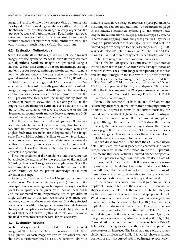
image in Fig. 15 and shows the corresponding output regionsside by side. The zoomed regions show significant skew, andthe character size in the bottom image is clearly larger than thetop one because of foreshortening. Rectification removesskew and restores uniform character size. Even thoughrectification does not take care of the blur in the top image, theoutput image is much more readable than the input.
4.2 Evaluation Methodology
Since it is difficult to obtain ground-truth 3D data for real
images, we use synthetic images to quantitatively evaluate
our algorithms. Synthetic images are generated using a
module [28] that takes as input a flat document image, a shape
model, a pose of the page with respect to the camera, a camera
focal length, and outputs the perspective image along with
ground-truth data such as 2D texture flow fields, 2D rulings,
vanishing points of rulings, and 3D surface normals. Our
evaluation module automatically generates a set of synthetic
images, compares the ground truth against the estimation,
and summarizes the average errors. Furthermore, we use the
OCR performance to measure the image quality from an
application point of view. That is, we apply OCR to the
original flat document, the synthetic curved document, and
the rectified document. We take the OCR text of the flat
document as ground truth and use that to compute the OCR
rates of the images before and after rectification.
For 2D texture flow fields, 2D rulings, and 3D surface
normals, which are vectors representing directions, we
measure their precision by their direction errors, which are
angles. Such measurements are independent of the image
scale. For vanishing points of rulings or camera focal length,
which are scalar numbers, a direct difference between the
truth and estimate is, however, dependent on the image scale.
Instead, we choose the following alternative benchmarks that
are scale independent.
First, the precision of the vanishing point of a ruling can
be equivalently measured by the precision of the induced
3D ruling direction. This gives us an angle value. Since the
3D ruling direction is also related to the position of the
optical center, we assume perfect knowledge of the focal
length at this step.
Second, we benchmark the focal length estimation in a
similar way. We take a reference point (other than the
principal point) in the image and compare two rays from this
point to the optical centers given by the correct focal length
and the estimated value, respectively, which provides an
angle difference. In our test, we choose one image cor-
ner—any corner produces equivalent result if the principal
point coincides with the image center—so the angle between
the ray and the optical axis has the physical interpretation of
being half of the field of view. By this interpretation, the error in
the field of view measures the focal length accuracy.
4.3 Evaluation Results
In the first experiment, we collected five clean document
images at 300 dots per inch (dpi). Their sizes are all 1; 600�2; 500 pixels. For each image, we created two other versions
that have some parts cropped to test our algorithms’ ability to
handle occlusion. We designed four sets of pose parameters,
including the rotation and translation of the document page
in the camera’s coordinate system, plus the camera focal
length. The combination of five pages, three cropped versions
(one without cropping), and four poses gives us 60 synthetic
images of planar documents (see Figs. 17a, 17b, and 17c). For
curved pages, we designed two cylinder shapes (see Fig. 17d),
which doubled the total number to 120. The first and last
images in Fig. 17d represent typical opened books, whereas
the other two images represent more general cases.
Due to the limit of space, we summarize the quantitative
evaluation results in Table 1. As for rectified images, not all of
them are shown. The output images corresponding to the first
and last input images in the last row in Fig. 17 are given in
Fig. 15. For more rectified images, see Figs. 5, 6, 15, and 16.The first half of Table 1 shows the evaluation on 2D and
3D features represented by angles in degrees. The second
half of the table compares the OCR performance before and
after rectification. We used OmniPage Pro 12 for OCR. All
the numbers are averages.
Overall, the accuracies of both 2D and 3D features are
satisfactory. In particular, we obtain an encouraging accuracy
of about 2.4 degrees in terms of 3D surface normals. For
curved pages, the effect of global shape optimization on top of
initial estimation is evident. Between curved and planar
pages, although the accuracies of 2D texture flow fields
(especially the major one) of curved pages is lower than that of
planar pages, the difference between 3D feature accuracies is
almost negligible. This demonstrates the robustness of our
model-based global shape optimization method.
We can draw two conclusions from the OCR comparison
data. First, even for planar pages, the character and word
recognition rates before rectification are below 30 percent.
This means that even without a curved shape, perspective
distortion presents a significant obstacle by itself. Second,
the image quality measured by OCR performance shows an
improvement of about threefold to fourfold after rectifica-
tion. Although there is still room for further improvement,
these rates are already acceptable in many document
analysis applications such as indexing and retrieval.
In the second experiment, we investigate our system’s
applicable range in terms of the curvature of the document
shape and its pose relative to the camera. In the first step, we
fix the pose parameter set and vary the shape parameter set.
We design seven shape models that gradually change from
almost flat to extremely curved (see Fig. 18a). Each shape is
applied to five document pages. The 3D feature evaluation
results are summarized in the first half of Table 2. In the
second step, we fix the shape and vary the pose. Again, we
design seven poses with gradually increasing tilt (Fig. 18b).
The evaluation results are shown in the second half of Table 2.
It is not surprising to see that the accuracy drops as the
curvature or tilt increases. The last shape and pose are rather
challenging as illustrated in Fig. 18c, which shows enlarged
portions of the most curved and tilted images, respectively.
LIANG ET AL.: GEOMETRIC RECTIFICATION OF CAMERA-CAPTURED DOCUMENT IMAGES 601

5 DISCUSSION
5.1 Implementation Variations
The rectification method described in Section 3.4 involvesmore complicated computation than the steps for planarpages (Section 3.3). The additional complexity is necessarybecause we assume a general developable surface model andunconstrained camera position. When additional constraintsare available, the framework can be tailored to reduce thecomplexity of the approach and improve its accuracy.
Opened books present a typical case of curved documentsin real life. An opened book usually forms a cylinder shape,and the minor texture flow vectors are all parallel and
coincide with the rulings of the surface. Under these
conditions, the ruling detection step (Section 3.4.2) is no
longer needed. Furthermore, the vanishing point of rulings is
simply the convergence point of minor texture flow vectors.
Thus, the step illustrated in Section 3.4.3 is not necessary
either. Inside the global shape optimization step (Sec-
tion 3.4.4), multiple rulings fRig reduce to a single R.
Combined together, these simplifications can result in a more
efficient and accurate system, provided that the input is
indeed an opened book.Another even simpler customization is to implement
only planar page rectification and shape classification
602 IEEE TRANSACTIONS ON PATTERN ANALYSIS AND MACHINE INTELLIGENCE, VOL. 30, NO. 4, APRIL 2008
Fig. 17. Synthetic document image samples. From left to right: (a) flat pages 1 through 5, (b) poses 1 through 4, (c) images with different croppings,
and (d) curved documents in which the first and the third come from one shape and the second and the fourth come from another shape; the second
and the third are cropped.

modules. When the input is classified as nonplanar, it isrejected, or the user can be prompted by an interactiveinterface to flatten the page and take another picture.
5.2 Parameter Selection
Besides the six weighting factors discussed in Section 3.4.4,there are two other user-defined parameters in ourframework.
The first one is a shape threshold (see Section 3.2.2) that
classifies a document as planar or curved. It is preferable to set
this parameter slightly in favor of a “planar” decision. First,
due to the inevitable noise in texture flow estimation, a
threshold that is too tight will in practice label any document
as “curved.” Second, the ultimate risk of labeling a weakly
curved page as planar is that text lines in the rectified image
may still be weakly bent; however, when a nearly planar page
is misclassified, the computation is much more expensive and
the output is more prone to errors. In our implementation, we
set this first threshold to 10�4.
The second parameter controls the division of text lines
into paragraphs (see Section 3.4.3). Because the vanishing-
point computation (10) requires at least three text lines in a
paragraph, usually, we tune the parameters in favor of
fewer paragraph cuts and more text lines in each para-
graph. In our experiments, the threshold is 10�2.
5.3 Future Work Directions
There are several limitations in our current method, and we
would like to address them in the future. First, one of our basic
assumptions is that the principal point is at the center of the
LIANG ET AL.: GEOMETRIC RECTIFICATION OF CAMERA-CAPTURED DOCUMENT IMAGES 603
TABLE 1Evaluation Summary of 2D/3D Features and OCR Performance
TABLE 2Effects of Curvature/Pose on 3D Shape Estimation
(FOV: field of view; N: surface normal).
Fig. 18. Images used for testing the applicable range of the rectification system. From left to right: (a) seven shapes with increasing curvature
(numbered 1 through 7), (b) seven poses with increasing tilt (numbered 1 through 7), and (c) enlarged details from the top part of the most curved
page in (a) and the most tilted page in (b).

image. Although this is usually true for the entire camera-
captured image, this does not hold if the image is cropped. To
deal with this, we would need a method for estimating the
position of the principal point. Second, currently, our method
only takes a single image as input. If multiple views are
available, they provide complementary information that
could improve the shape estimation accuracy. Third, our
method does not rely on 3D range scanning or 2D metric data.
However, when such information is available (for example,
from an inexpensive and low-resolution infrared (IR) camera
attached to the optical camera), it is desirable to incorporate it
into the computation.
6 CONCLUSION
For camera-based document analysis, especially mobile
applications, the distortion introduced by nonplanar docu-
ment surfaces and perspective projection is one of the critical
challenges, if not the most important. We solve this problem
with an automatic rectification approach that takes advan-
tage of the developable surface constraint on curved pages
and the properties of printed text in documents. Given a
camera-captured image of a document, we estimate the
3D shape of the page, as well as the camera’s focal length,
based on texture flow fields extracted from the view and then
restore the flat document image. With this method, a camera
can emulate the function of a scanner and be used in various
situations where scanners would be cumbersome or im-
practical. In the experiments, we obtained a significant
improvement in OCR performance after rectification. The
accuracy of shape estimation is also satisfactory, especially
considering that we have only a single image without camera
calibration. Our system can serve as a preprocessing unit in
camera-based OCR applications, or the rectified images can
be directly archived or presented for human viewing.
REFERENCES
[1] J. Liang, D. Doermann, and H. Li, “Camera-Based Analysis of Textand Documents: A Survey,” Int’l J. Document Analysis andRecognition, vol. 7, no. 2-3, pp. 84-104, July 2005.
[2] M.J. Taylor, A. Zappala, W.M. Newman, and C.R. Dance,“Documents through Cameras,” Image and Vision Computing,vol. 17, no. 11, pp. 831-844, 1999.
[3] L. O’Gorman, “The Document Spectrum for Page LayoutAnalysis,” IEEE Trans. Pattern Analysis and Machine Intelligence,vol. 15, no. 11, pp. 1162-1173, Nov. 1993.
[4] G. Nagy, S. Seth, and M. Viswanathan, “A Prototype DocumentImage Analysis System for Technical Journals,” Computer, vol. 25,no. 7, pp. 10-22, July 1992.
[5] A.K. Jain and B. Yu, “Document Representation and Its Applica-tion to Page Decomposition,” IEEE Trans. Pattern Analysis andMachine Intelligence, vol. 20, no. 3, pp. 294-308, Mar. 1998.
[6] M.S. Brown and W.B. Seales, “Image Restoration of ArbitrarilyWarped Documents,” IEEE Trans. Pattern Analysis and MachineIntelligence, vol. 26, no. 10, pp. 1295-1306, Oct. 2004.
[7] S. Pollard and M. Pilu, “Building Cameras for CapturingDocuments,” Int’l J. Document Analysis and Recognition, vol. 7,nos. 2-3, pp. 123-137, July 2005.
[8] A. Ulges, C.H. Lampert, and T. Breuel, “Document Capture UsingStereo Vision,” Proc. 2004 ACM Symp. Document Eng., pp. 198-200,2004.
[9] P. Clark and M. Mirmehdi, “On the Recovery of OrientedDocuments from Single Images,” Proc. Advanced Concepts forIntelligent Vision Systems, pp. 190-197, 2002.
[10] H. Cao, X. Ding, and C. Liu, “A Cylindrical Surface Model toRectify the Bound Document Image,” Proc. Ninth Int’l Conf.Computer Vision, vol. 1, p. 228, 2003.
[11] Y.-C. Tsoi and M.S. Brown, “Geometric and Shading Correctionfor Images of Printed Materials a Unified Approach UsingBoundary,” Proc. IEEE Conf. Computer Vision and Pattern Recogni-tion, pp. 240-246, 2004.
[12] N. Gumerov, A. Zandifar, R. Duraiswarni, and L.S. Davis,“Structure of Applicable Surfaces from Single Views,” Proc. EighthEuropean Conf. Computer Vision, pp. 482-496, 2004.
[13] Z. Zhang and C.L. Tan, “Correcting Document Image WarpingBased on Regression of Curved Text Lines,” Proc. Seventh Int’lConf. Document Analysis and Recognition, vol. 1, pp. 589-593, 2003.
[14] P. Clark and M. Mirmehdi, “Estimating the Orientation andRecovery of Text Planes in a Single Image,” Proc. British MachineVision Conf., pp. 421-430, 2001.
[15] A. Ulges, C.H. Lampert, and T.M. Breuel, “Document ImageDewarping Using Robust Estimation of Curled Text Lines,” Proc.Eighth Int’l Conf. Document Analysis and Recognition, pp. 1001-1005,2005.
[16] H. Cao, X. Ding, and C. Liu, “Rectifying the Bound DocumentImage Captured by the Camera: A Model Based Approach,” Proc.Seventh Int’l Conf. Document Analysis and Recognition, pp. 71-75,2003.
[17] A. Zappala, A. Gee, and M.J. Taylor, “Document Mosaicing,”Image and Vision Computing, vol. 17, no. 8, pp. 585-595, 1999.
[18] T. Nakao, A. Kashitani, and A. Kaneyoshi, “Scanning a Documentwith a Small Camera Attached to a Mouse,” Proc. Fourth IEEEWorkshop Applications of Computer Vision, pp. 63-68, 1998.
[19] G.K. Myers, R.C. Bolles, Q.-T. Luong, J.A. Herson, and H.B.Aradhye, “Rectification and Recognition of Text in 3-D Scenes,”Int’l J. Document Analysis and Recognition, vol. 7, nos. 2-3, pp. 147-158, July 2005.
[20] J. Malik and R. Rosenholtz, “Computing Local Surface Orientationand Shape from Texture for Curved Surfaces,” Int’l J. ComputerVision, vol. 23, no. 2, pp. 149-168, 1997.
[21] J. Garding, “Shape from Texture for Smooth Curved Surfaces inPerspective Projection,” J. Math. Imaging and Vision, vol. 2, pp. 327-350, 1992.
[22] O. Ben-Shahar and S.W. Zucker, “The Perceptual Organization ofTexture Flow: A Contextual Inference Approach,” IEEE Trans.Pattern Analysis and Machine Intelligence, vol. 25, no. 4, pp. 401-417,Apr. 2003.
[23] A.R. Rao and R.C. Jain, “Computerized Flow Field Analysis:Oriented Texture Fields,” IEEE Trans. Pattern Analysis and MachineIntelligence, vol. 14, no. 7, pp. 693-709, July 2003.
[24] D.C. Knill, “Contour into Texture: Information Content of SurfaceContours and Texture Flow,” J. Optical Soc. Am. Assoc., vol. 18,no. 1, pp. 12-35, Jan. 2001.
[25] J. Liang, D. DeMenthon, and D. Doermann, “Flattening CurvedDocuments in Images,” Proc. IEEE Conf. Computer Vision andPattern Recognition, pp. 338-345, 2005.
[26] D.X. Le, G.R. Thomas, and H. Weschler, “Automated PageOrientation and Skew Angle Detection for Binary DocumentImages,” Pattern Recognition, vol. 27, no. 10, pp. 1325-1344, 1994.
[27] R.A. Hummel and S.W. Zucker, “On the Foundations ofRelaxation Labeling Processes,” IEEE Trans. Pattern Analysis andMachine Intelligence, vol. 5, pp. 267-287, 1983.
[28] J. Liang, “Processing Camera-Captured Document Images: Geo-metric Rectification, Mosaicing, and Layout Structure Recogni-tion,” PhD dissertation, Univ. of Maryland, College Park, 2006.
[29] R. Hartley and A. Zisserman, Multiple View Geometry in ComputerVision. Cambridge Univ. Press, 2000.
[30] D. Liebowitz and A. Zisserman, “Metric Rectification forPerspective Images of Planes,” Proc. IEEE Conf. Computer Visionand Pattern Recognition, pp. 482-488, 1998.
[31] A. Vailaya, H. Zhang, C. Yang, F.-I. Liu, and A. Jain, “AutomaticImage Orientation Detection,” IEEE Trans. Image Processing,vol. 11, no. 7, pp. 746-755, 2002.
[32] D.B. Wagner, “Dynamic Programming,” The Mathematica J., vol. 5,no. 4, pp. 42-51, 1995.
[33] T. Coleman and Y. Li, “An Interior Trust Region Approach forNonlinear Minimization Subject to Bounds,” SIAM J. Optimization,vol. 6, pp. 418-445, 1996.
604 IEEE TRANSACTIONS ON PATTERN ANALYSIS AND MACHINE INTELLIGENCE, VOL. 30, NO. 4, APRIL 2008

Jian Liang received the BS and MS degrees inelectronic engineering from Tsinghua University,China, and the PhD degree in electrical engineer-ing from the University of Maryland, CollegePark. During his PhD study, he was with theLanguage and Media Processing Laboratory,Center for Automation Research, focusing ondocument image processing. His research topicsinclude document layout analysis, documentclassification, logical component labeling, cam-
era-based document analysis, geometric rectification of camera-cap-tured documents, and mosaicing of camera-captured documents. Since2006, he has been with Amazon.com, designing and developing print-on-demand systems. His main research interests include digital imageprocessing, pattern recognition, machine learning, and large-scaledocument processing systems. He is a member of the IEEE.
Daniel DeMenthon received the ME degreefrom the Ecole Centrale de Lyon, France, in1972, the MS degree in applied mathematicsfrom Universite Claude Bernard, Lyon, France,in 1973, the MS degree in offshore engineeringand naval architecture from the University ofCalifornia, Berkeley, in 1980, and the PhDdegree in computer science from UniversiteJoseph Fourier, Grenoble, France, in 1993, witha thesis describing research performed in the
Computer Vision Laboratory (CVL), University of Maryland, and focusedon the design of a 3D mouse using computer vision. He is currentlyserving as a program director for computer vision research at the USNational Science Foundation. He is also an associate researchprofessor with the Institute for Advanced Computer Studies, Universityof Maryland. He did research in computational fluid dynamics atHydronautics, Inc., in the 1980s. He developed fast algorithms for pose(POSIT and softPOSIT) and segmentation (Hierarchical Mean Shift). Heis the author of five US patents and three European patents and editedthe book Video Mining with Azriel Rosenfeld and David Doermann. Hiscurrent interests are in document image processing and classification,object recognition, and fast alignment between video streams and3D models of cities. For details, see http://www.cfar.umd.edu/~daniel.He is a member of the IEEE and the IEEE Computer Society.
David Doermann received the BSc degree incomputer science and mathematics fromBloomsburg University in 1987, and the MScdegree from the Department of ComputerScience, University of Maryland, College Park,in 1989, and the PhD degree from the ComputerVision Laboratory, University of Maryland, in1993. Since 1993, he has been serving as acodirector of the Laboratory for Language andMedia Processing, Institute for Advanced Com-
puter Studies, University of Maryland, and as an adjunct member of thegraduate faculty. His team of 15-20 researchers focuses on topicsrelated to document image analysis and multimedia informationprocessing. Recent intelligent document image analysis projects includepage decomposition, structural analysis and classification, pagesegmentation, logo recognition, document image compression, dupli-cate document image detection, image-based retrieval, characterrecognition, generation of synthetic optical character recognition(OCR) data, and signature verification. In video processing, projectshave centered on the segmentation of compressed domain videosequences, structural representation and classification of video, detec-tion of reformatted video sequences and the performance evaluation ofautomated video analysis algorithms. He is the coeditor of theInternational Journal on Document Analysis and Recognition. He hasmore than 25 journal publications and almost 100 refereed conferenceproceedings papers. He is a member of the IEEE and the IEEEComputer Society.
. For more information on this or any other computing topic,please visit our Digital Library at www.computer.org/publications/dlib.
LIANG ET AL.: GEOMETRIC RECTIFICATION OF CAMERA-CAPTURED DOCUMENT IMAGES 605