Embed Size (px)
Citation preview
Geological and Practical Aspects of
Deep Borehole Disposal
Sandia National Laboratories is a multi-program
laboratory managed and operated by Sandia Corporation, a wholly
owned subsidiary of Lockheed Martin Corporation, for the U.S.
Department of Energy’s National Nuclear Security Administration under
contract DE-AC04-94AL85000.
Nuclear Waste Technical Review Board
Spring Meeting
Albuquerque, New Mexico
March 7, 2012
Bill Arnold and Pat Brady
Sandia National Laboratories
SAND2012-1383C
Outline
Deep borehole disposal concept
Geological aspects of disposal system safety and
borehole siting
Reference design and operations for a deep
borehole disposal system
Practical aspects of deep borehole disposal
Conclusions
2
Deep Borehole Disposal Concept
Disposal concept consists of drilling a borehole or array of boreholes
into crystalline basement rock to about 5,000 m depth
Approximately 400 waste canisters would be emplaced in the lower
2,000 m of the borehole
Upper borehole would be sealed with compacted bentonite clay and
cement plugs
Several factors suggest the disposal concept is viable and safe:
• Crystalline basement rocks are common in many stable continental regions
• Existing drilling technology permits dependable construction at acceptable cost
• Low permeability and long residence time of high-salinity groundwater in deep
continental crystalline basement at many locations suggests very limited interaction
with shallow fresh groundwater resources
• Geochemically reducing conditions at depth limit the solubility and enhance the
sorption of many radionuclides in the waste
• Density stratification of saline groundwater underlying fresh groundwater would
oppose thermally induced groundwater convection
3
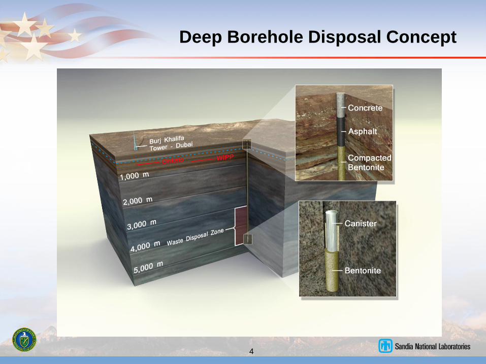
Deep Borehole Disposal Concept
4
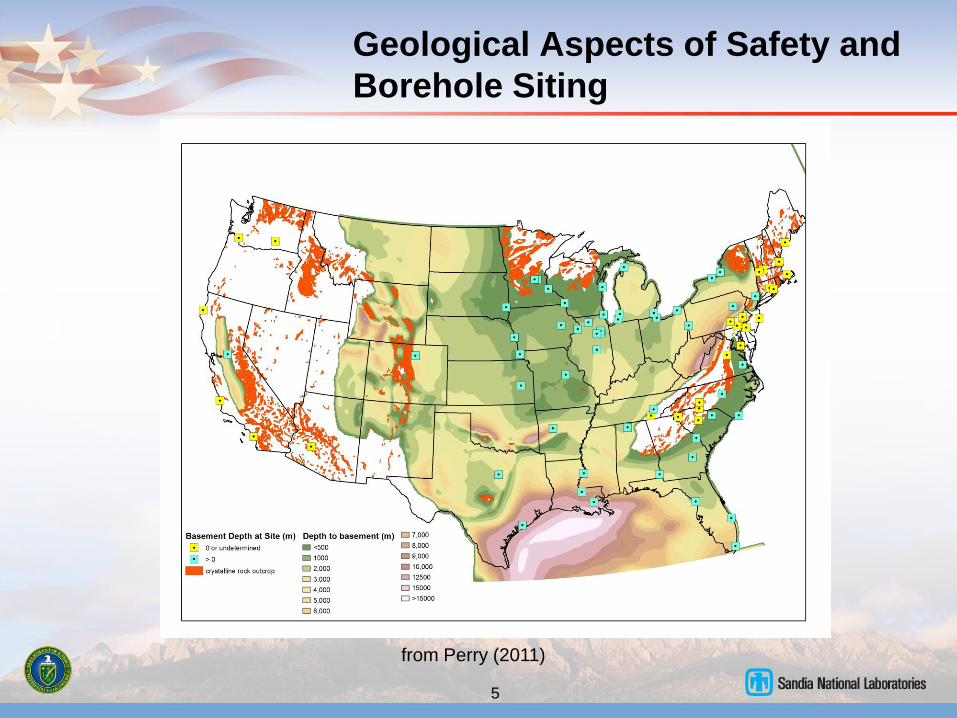
Geological Aspects of Safety and
Borehole Siting
5
from Perry (2011)
Geological Aspects of Safety and
Borehole Siting
Geological characterization should focus on conditions that are
undesirable for the deep borehole disposal concept and waste isolation:
Young meteoric groundwater at depths of greater than 3 km
Low-salinity, oxidizing groundwater at depths of greater than 3 km
Economically exploitable natural resources at depths of greater than 3 km
Significant upward gradient in fluid potential (overpressured conditions)
from below 3 km depth
Natural interconnected zone of high permeability from the waste disposal
zone to the surface or shallow subsurface environment (e.g., fault zone)
Occurrence of Quaternary-age volcanic rocks or igneous intrusions
In the absence of these unfavorable features, the most likely scenario for
release of radionuclides to the biosphere is thermally driven groundwater
flow (from waste heat) through the borehole or surrounding disturbed
rock zone
6
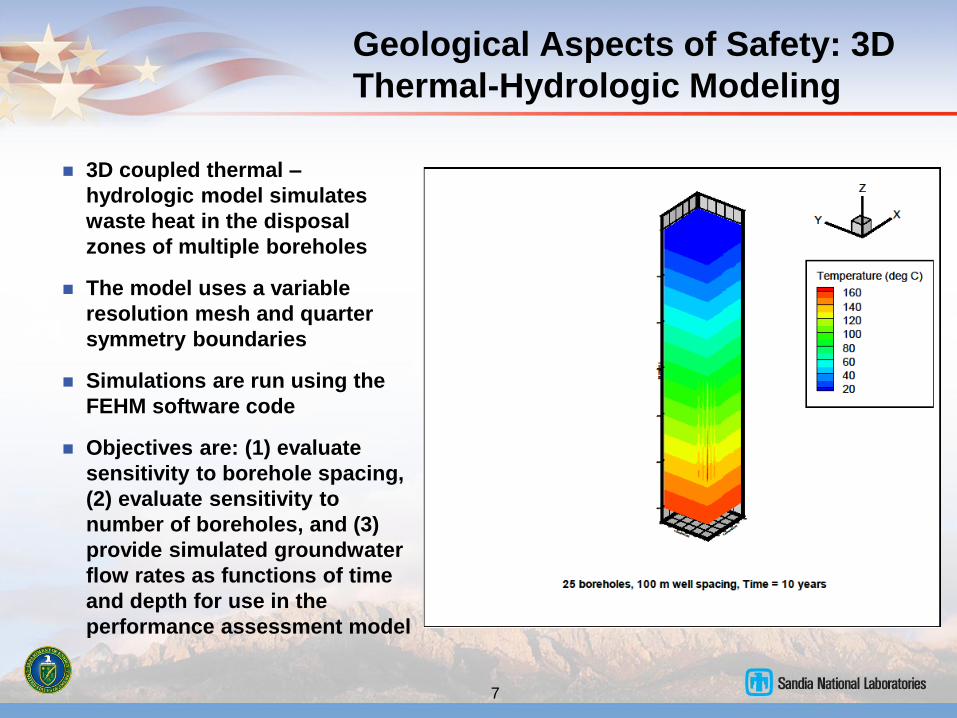
Geological Aspects of Safety: 3D
Thermal-Hydrologic Modeling
3D coupled thermal –
hydrologic model simulates
waste heat in the disposal
zones of multiple boreholes
The model uses a variable
resolution mesh and quarter
symmetry boundaries
Simulations are run using the
FEHM software code
Objectives are: (1) evaluate
sensitivity to borehole spacing,
(2) evaluate sensitivity to
number of boreholes, and (3)
provide simulated groundwater
flow rates as functions of time
and depth for use in the
performance assessment model
7
Geological Aspects of Safety: 3D
Thermal-Hydrologic Modeling
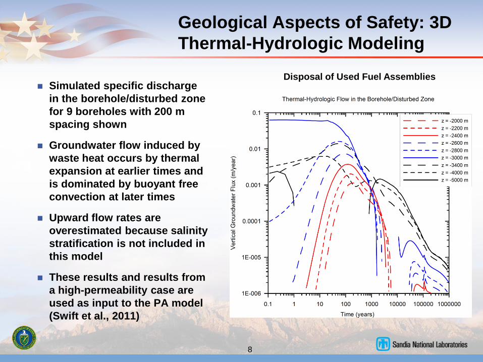
Simulated specific discharge
in the borehole/disturbed zone
for 9 boreholes with 200 m
spacing shown
Groundwater flow induced by
waste heat occurs by thermal
expansion at earlier times and
is dominated by buoyant free
convection at later times
Upward flow rates are
overestimated because salinity
stratification is not included in
this model
These results and results from
a high-permeability case are
used as input to the PA model
(Swift et al., 2011)
8
Disposal of Used Fuel Assemblies
Geological Aspects of Safety: 2D
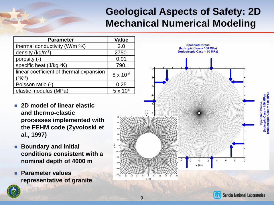
Mechanical Numerical Modeling
2D model of linear elastic
and thermo-elastic
processes implemented with
the FEHM code (Zyvoloski et
al., 1997)
Boundary and initial
conditions consistent with a
nominal depth of 4000 m
Parameter values
representative of granite
9
Parameter Value
thermal conductivity (W/m oK) 3.0
density (kg/m3) 2750.
porosity (-) 0.01
specific heat (J/kg oK) 790.
linear coefficient of thermal expansion
(oK-1) 8 x 10⁻⁶
Poisson ratio (-) 0.25
elastic modulus (MPa) 5 x 10⁴

Geological Aspects of Safety: 2D
Mechanical Modeling
For differential horizontal stress (anisotropic
case), the host rock is placed in
compression in the direction of maximum
horizontal stress and in extension in the
direction of minimum horizontal stress
Concentration of stress at the borehole walls
in the direction of minimum horizontal stress
can result in borehole breakouts (not
explicitly analyzed here)
Permeability will be increased by extensional
strain and decreased by compression
Permeability changes are a function of
strain, fracture porosity, and fracture
orientation – sensitivity is amplified by the
cubic relationship between permeability and
fracture aperture
10
Geological Aspects of Safety: 2D
Thermal-Mechanical Modeling
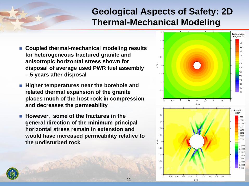
Coupled thermal-mechanical modeling results
for heterogeneous fractured granite and
anisotropic horizontal stress shown for
disposal of average used PWR fuel assembly
– 5 years after disposal
Higher temperatures near the borehole and
related thermal expansion of the granite
places much of the host rock in compression
and decreases the permeability
However, some of the fractures in the
general direction of the minimum principal
horizontal stress remain in extension and
would have increased permeability relative to
the undisturbed rock
11
Reference Design and Operations:
Objectives and Requirements
Overarching objective: A simple and
achievable, internally consistent system for
waste disposal that meets regulatory
requirements for operational and public
safety
Update and refine the conceptual design
presented in Brady et al. (2009)
Consider preliminary design alternatives
Provide a reference design for performance
assessment and risk analysis
Provide a reference design for more
accurate cost estimates
Numerous viable design alternatives exist –
this reference design is one choice that
provides a basis for the objectives stated
above
12
Arnold et al. (2011)
Reference Design and Operations:
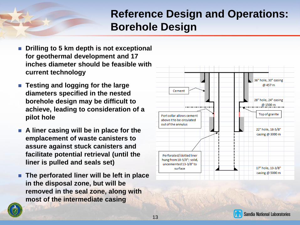
Borehole Design
Drilling to 5 km depth is not exceptional
for geothermal development and 17
inches diameter should be feasible with
current technology
Testing and logging for the large
diameters specified in the nested
borehole design may be difficult to
achieve, leading to consideration of a
pilot hole
A liner casing will be in place for the
emplacement of waste canisters to
assure against stuck canisters and
facilitate potential retrieval (until the
liner is pulled and seals set)
The perforated liner will be left in place
in the disposal zone, but will be
removed in the seal zone, along with
most of the intermediate casing
13
Reference Design and Operations:
Waste Canister Design
14
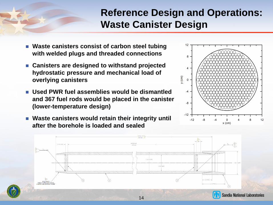
Waste canisters consist of carbon steel tubing
with welded plugs and threaded connections
Canisters are designed to withstand projected
hydrostatic pressure and mechanical load of
overlying canisters
Used PWR fuel assemblies would be dismantled
and 367 fuel rods would be placed in the canister
(lower-temperature design)
Waste canisters would retain their integrity until
after the borehole is loaded and sealed
Reference Design and Operations:
Waste Canister Emplacement
15
from Woodward-Clyde Consultants (1983)
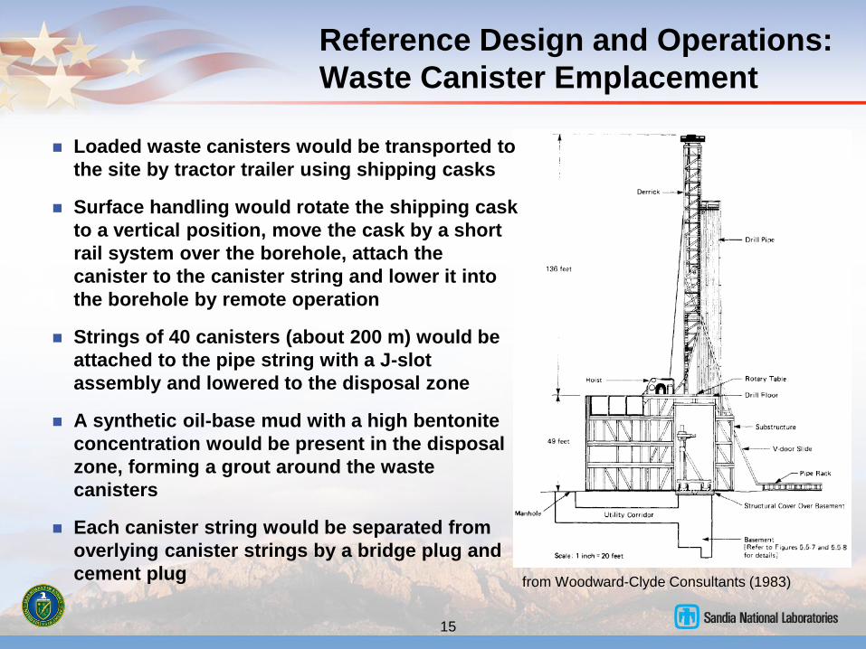
Loaded waste canisters would be transported to
the site by tractor trailer using shipping casks
Surface handling would rotate the shipping cask
to a vertical position, move the cask by a short
rail system over the borehole, attach the
canister to the canister string and lower it into
the borehole by remote operation
Strings of 40 canisters (about 200 m) would be
attached to the pipe string with a J-slot
assembly and lowered to the disposal zone
A synthetic oil-base mud with a high bentonite
concentration would be present in the disposal
zone, forming a grout around the waste
canisters
Each canister string would be separated from
overlying canister strings by a bridge plug and
cement plug
Reference Design and Operations:
Waste Canister Emplacement
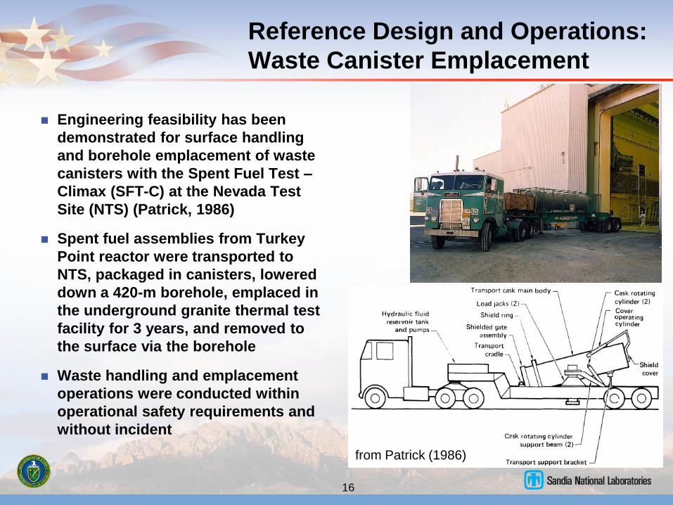
Engineering feasibility has been
demonstrated for surface handling
and borehole emplacement of waste
canisters with the Spent Fuel Test –
Climax (SFT-C) at the Nevada Test
Site (NTS) (Patrick, 1986)
Spent fuel assemblies from Turkey
Point reactor were transported to
NTS, packaged in canisters, lowered
down a 420-m borehole, emplaced in
the underground granite thermal test
facility for 3 years, and removed to
the surface via the borehole
Waste handling and emplacement
operations were conducted within
operational safety requirements and
without incident
16
from Patrick (1986)
Reference Design and Operations:
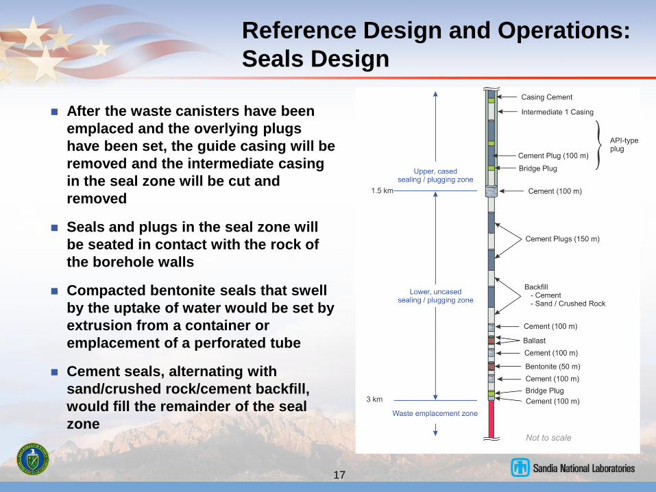
Seals Design
After the waste canisters have been
emplaced and the overlying plugs
have been set, the guide casing will be
removed and the intermediate casing
in the seal zone will be cut and
removed
Seals and plugs in the seal zone will
be seated in contact with the rock of
the borehole walls
Compacted bentonite seals that swell
by the uptake of water would be set by
extrusion from a container or
emplacement of a perforated tube
Cement seals, alternating with
sand/crushed rock/cement backfill,
would fill the remainder of the seal
zone
17
Practical Aspects of Deep
Borehole Disposal
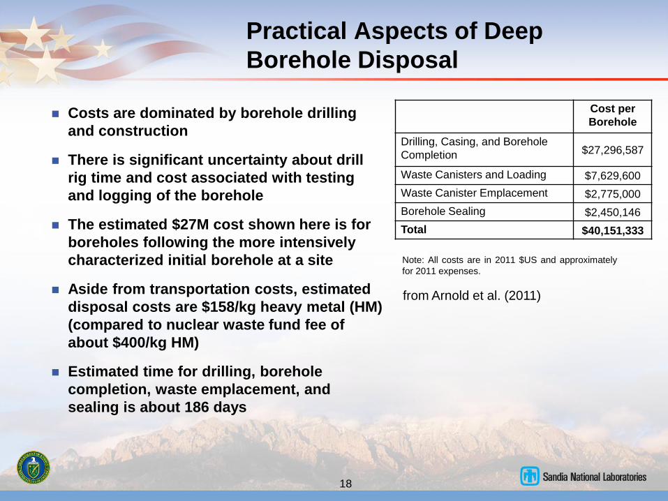
Costs are dominated by borehole drilling
and construction
There is significant uncertainty about drill
rig time and cost associated with testing
and logging of the borehole
The estimated $27M cost shown here is for
boreholes following the more intensively
characterized initial borehole at a site
Aside from transportation costs, estimated
disposal costs are $158/kg heavy metal (HM)
(compared to nuclear waste fund fee of
about $400/kg HM)
Estimated time for drilling, borehole
completion, waste emplacement, and
sealing is about 186 days
18
Cost per
Borehole
Drilling, Casing, and Borehole
Completion $27,296,587
Waste Canisters and Loading $7,629,600
Waste Canister Emplacement $2,775,000
Borehole Sealing $2,450,146
Total $40,151,333
Note: All costs are in 2011 $US and approximately
for 2011 expenses.
from Arnold et al. (2011)
Practical Aspects of Deep
Borehole Disposal
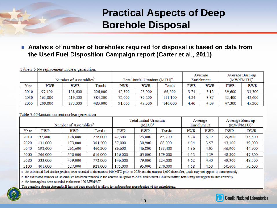
Analysis of number of boreholes required for disposal is based on data from
the Used Fuel Disposition Campaign report (Carter et al., 2011)
19
Practical Aspects of Deep
Borehole Disposal
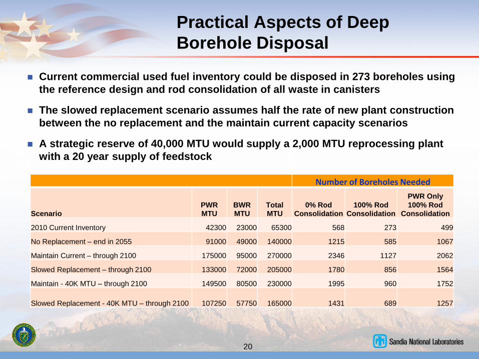
Current commercial used fuel inventory could be disposed in 273 boreholes using
the reference design and rod consolidation of all waste in canisters
The slowed replacement scenario assumes half the rate of new plant construction
between the no replacement and the maintain current capacity scenarios
A strategic reserve of 40,000 MTU would supply a 2,000 MTU reprocessing plant
with a 20 year supply of feedstock
20
Number of Boreholes Needed
Scenario PWR
MTU BWR
MTU Total
MTU 0% Rod
Consolidation 100% Rod
Consolidation
PWR Only
100% Rod
Consolidation
2010 Current Inventory 42300 23000 65300 568 273 499
No Replacement – end in 2055 91000 49000 140000 1215 585 1067
Maintain Current – through 2100 175000 95000 270000 2346 1127 2062
Slowed Replacement – through 2100 133000 72000 205000 1780 856 1564
Maintain - 40K MTU – through 2100 149500 80500 230000 1995 960 1752
Slowed Replacement - 40K MTU – through 2100 107250 57750 165000 1431 689 1257
Conclusions
21
Most important undesirable or adverse geological conditions for deep
borehole disposal should be the focus of site characterization
The most likely nominal release scenario has been evaluated with
thermal-hydrologic and performance assessment modeling
Mechanical and thermal-mechanical effects on the disturbed rock zone
have been modeled – volumetric strain and altered permeability are
related to the differential in horizontal stress
A feasible and simple reference design and operations have been
developed for a deep borehole disposal system
Estimated cost for deep borehole disposal using the reference design,
excluding transportation costs, is about $158/kg HM, well below the
$400/kg waste fund fee
The current used fuel inventory could be disposed in 273 boreholes
using the reference design – the 2055 inventory in the current reactor
fleet could be disposed in 585 boreholes
References
22
Arnold, B.W., P.V. Brady, S.J. Bauer, C. Herrick, S. Pye, and J. Finger, 2011, Reference Design and
Operations for Deep Borehole Disposal of High-Level Radioactive Waste, SAND2011-6749, Sandia National
Laboratories, Albuquerque, NM.
Brady, P.V., B.W. Arnold, G.A. Freeze, P.N. Swift, S.J. Bauer, J.L. Kanney, R.P. Rechard, J.S. Stein, 2009,
Deep Borehole Disposal of High-Level Radioactive Waste, SAND2009-4401, Sandia National Laboratories,
Albuquerque, NM.
Carter, J.T., A.J. Luptak, J. Gastelum, C. Stockman, A. Miller, 2011, Fuel Cycle Potential Waste Inventory for
Disposition, FCR&D-USED-2010-000031 Rev 4, Fuel Cycle Research and Development, U.S. Department of
Energy.
Patrick, W.C.,1986, Spent Fuel Test – Climax: An Evaluation of the Technical Feasibility of Geologic Storage
of Spent Nuclear Fuel in Granite – Final Report, UCRL-53702, Lawrence Livermore National Laboratory,
Livermore, CA.
Perry, F., 2011, GIS Map of Depth to Crystalline Basement, personal communication, Los Alamos National
Laboratory.
Swift, P.N., B.W. Arnold, P.V. Brady, G. Freeze, T. Hadgu, J.H. Lee, and Y. Wang, 2011, Preliminary
Performance Assessment for Deep Borehole Disposal of High-Level Radioactive Waste, proceedings of the
2011 International High-Level Radioactive Waste Management Conference, April 10-14, 2011, Albuquerque,
NM.
Woodward - Clyde Consultants,1983, Very Deep Hole Systems Engineering Studies. Columbus, OH, ONWI.
Zyvoloski, G. A., B. A. Robinson, et al., 1997, Summary of Models and Methods for FEHM Application – A
Finite Element Heat and Mass Transfer Code, Los Alamos National Laboratory Report LA-13307-MS, Los
Alamos, NM.