Embed Size (px)
Citation preview
1 INTRODUCTION
Expansive soils are highly plastic clay, spread widely in the arid and semi-arid areas. The soils are char-acterized with high susceptibility to swelling during wetting subsequently low bearing capacity, and to shrinkage accompanied with vertical cracks due to desiccation. Roads constructed on these soils are ex-posed to damages due to the annual heave and shrink of the soils. Conventionally the soil is either exca-vated and replaced with non-swelling soil or treated by chemical stabilization. The addition of lime and/or cement improves efficiently the subgrade soil in road and airfield constructions by increasing the soil bearing capacity and restraining the swelling-shrinkage behaviour.
Geosynthetics, either geotextiles or geogrids, have been intensively applied with coarse-grained mate-rials to increase the strength of pavement, to reduce the vertical deformation due to traffic loading, and ei-ther to reduce the pavement thickness or to extend its life span. Few researchers investigated the effect of geosynthetics in restraining the swelling-shrinkage behaviour of expansive soils. AL-OMARI and HAMODI (1991) studied the feasibility of a cylindrical geogrid in controlling the swelling of highly plas-tic clay; the geogrid was embedded vertically in the swelling direction and tested in an enlarged oedome-ter device. They declared that geogrid inclusion reduced the vertical swelling with 17-51% depending on the geogrid stiffness. AL-OMARI and ORAIBI (2000) investigated the cyclic wetting-drying of expan-sive soils reinforced with a cylindrical geogrid embedded vertically in the swelling direction and tested in an enlarge oedometer device under a surcharge of 7 kPa. The samples were wetted to achieve full swell-
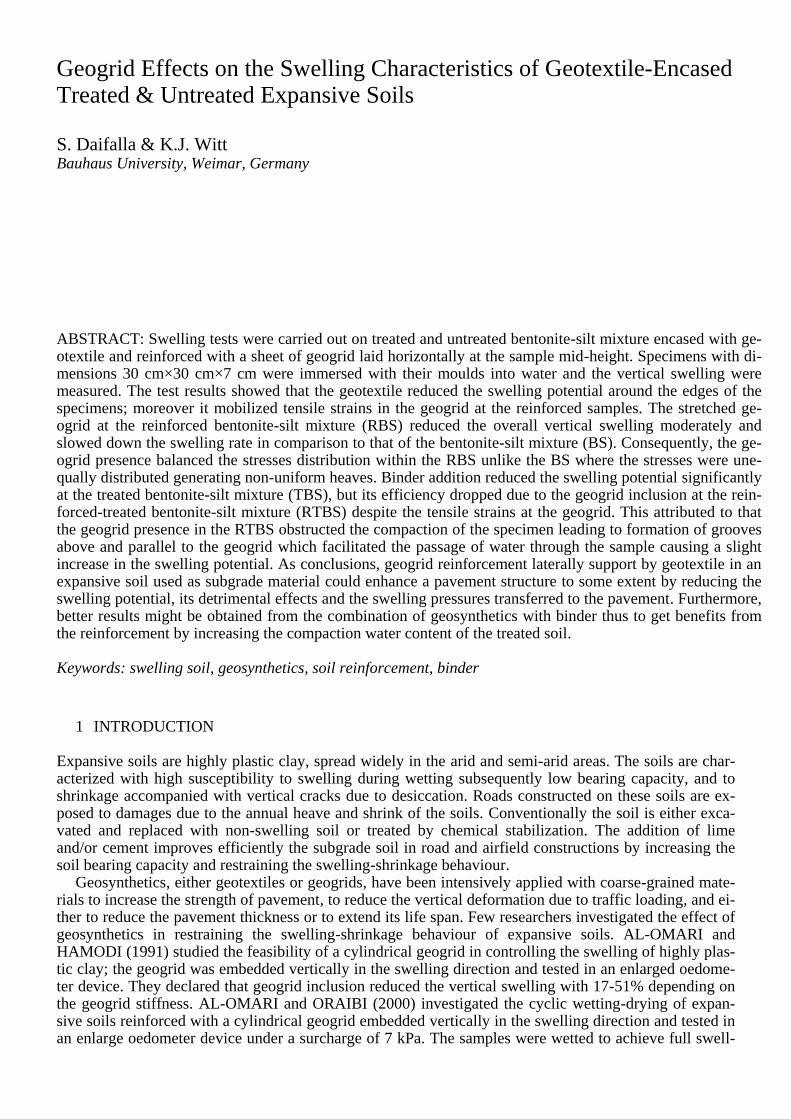
Geogrid Effects on the Swelling Characteristics of Geotextile-Encased Treated & Untreated Expansive Soils
S. Daifalla & K.J. Witt Bauhaus University, Weimar, Germany
ABSTRACT: Swelling tests were carried out on treated and untreated bentonite-silt mixture encased with ge-otextile and reinforced with a sheet of geogrid laid horizontally at the sample mid-height. Specimens with di-mensions 30 cm×30 cm×7 cm were immersed with their moulds into water and the vertical swelling were measured. The test results showed that the geotextile reduced the swelling potential around the edges of the specimens; moreover it mobilized tensile strains in the geogrid at the reinforced samples. The stretched ge-ogrid at the reinforced bentonite-silt mixture (RBS) reduced the overall vertical swelling moderately and slowed down the swelling rate in comparison to that of the bentonite-silt mixture (BS). Consequently, the ge-ogrid presence balanced the stresses distribution within the RBS unlike the BS where the stresses were une-qually distributed generating non-uniform heaves. Binder addition reduced the swelling potential significantly at the treated bentonite-silt mixture (TBS), but its efficiency dropped due to the geogrid inclusion at the rein-forced-treated bentonite-silt mixture (RTBS) despite the tensile strains at the geogrid. This attributed to that the geogrid presence in the RTBS obstructed the compaction of the specimen leading to formation of grooves above and parallel to the geogrid which facilitated the passage of water through the sample causing a slight increase in the swelling potential. As conclusions, geogrid reinforcement laterally support by geotextile in an expansive soil used as subgrade material could enhance a pavement structure to some extent by reducing the swelling potential, its detrimental effects and the swelling pressures transferred to the pavement. Furthermore, better results might be obtained from the combination of geosynthetics with binder thus to get benefits from the reinforcement by increasing the compaction water content of the treated soil.
Keywords: swelling soil, geosynthetics, soil reinforcement, binder
ing and then were partially or fully dried. Depending on the geogrid stiffness, the reinforcement reduced the swelling and shrinkage behaviour with 37-50% at the first cycle and 55-81% at the steady state during wetting; and with 49-74% at the first cycle and 55-81% at the steady state during drying. VESSELY and WU (2002) tested the behaviour of geotextile-reinforced lean clay during wetting with laying the geotex-tile horizontally at the sample mid-height. The samples were allowed to swell in both vertical and hori-zontal directions. Their results showed that inclusion of the geotextile did not affect the swelling in the vertical direction but it reduced the lateral swelling with 30-40%. PATHAK and ALFARO (2010) inves-tigated the performance of geogrid-reinforced highly plastic clay during wetting and drying tests under vertical and lateral pressures. The geogrid was horizontally placed at the mid-height of the clay speci-mens. They declared that the geogrid reduced the horizontal strain by 20% whereas its influence on the vertical strain was negligible. Hence, the aforementioned studies show that the effect of geosynthetics in reducing the swelling-shrinkage potential of expansive soil is considerably moderate when they are ori-ented in the swelling direction, while their effect is negligible or minor when they are placed perpendicu-larly to the swelling direction.
This study investigated reduction in the vertical heave of bentonite-silt mixture by mobilizing tensile strains in the geogrid through encasing the soil with geotextile. The geogrid was horizontally laid at the sample mid-height. The reduction in the vertical heave from the geosynthetics during swelling tests with treated bentonite-silt mixture was also studied. The aim of this study was to investigate the beneficial ef-fects provided by the application of geogrid laterally supported with geotextile in reducing the swelling potential of an expansive soil used as a subgrade material, thus in reducing the dumping and hauling of the excavated and replaced soil.
2 LABORATORY TESTING PROGRAM
Swelling tests were performed on bentonite-silt mixture (BS), reinforced bentonite-silt mixture (RBS), treated bentonite-silt mixture (TBS), and reinforced-treated bentonite-silt mixture (RTBS) as indicated Table 1. Specimens with dimensions 30 cm×30 cm×7 cm were prepared at identical conditions, i.e. com-pacted to the maximum dry density and the optimum water content of the bentonite-silt mixture (BS) ob-tained from the standard proctor test.
In the reinforced samples, a sheet of geogrid covering an area 30 cm×30 cm was laid horizontally at the sample mid-height, thus the geogrid might enhance the bearing capacity as well which could be proved by CBR tests. To mobilize tensile strains at the geogrid ribs, geotextile sheets with a relatively rough surface were vertically fixed on the inside walls of the moulds used to prepare the specimens. Moreover, the geotextile sheets would provide resistance to the swelling potential at the edges of the specimens, prevent sticking of the specimens on the mould walls and facilitate removal of the specimens from their moulds after testing.
The type of binder used for treatment was a mixture of quick lime and cement. The samples for the swelling tests were treated with the optimum addition of binder which was 6% of the dry mass of the BS mixture.
Table 1. Summary of Testing Program ______________________________________________ Sample Description Sample Designation ______________________________________________ Bentonite-Silt Mixture BS Reinforced Bentonite-Silt Mixture RBS Treated Bentonite-Silt Mixture TBS Reinforced Treated Bentonite-Silt Mixture RTBS ______________________________________________
3 MATERIALS
3.1 Bentonite-Silt Mixture
The expansive soil used in this study was a mixture of Na-bentonite and non-swelling soil. The non-swelling soil was silt collected from Apolda, Germany. To prepare expansive soil, Atterberg limits tests were carried out on several mixtures with different percentages of the Na-bentonite added to the silt. From the test results, 20% by the soil dry mass of sodium bentonite added to Apolda silt was sufficient to produce appreciable swelling characteristics. Table 2 displays the physical material properties of Apolda silt, the Na-bentonite, the bentonite-silt mixture besides the mechanical properties of the bentonite-silt
mixture. All tests were carried out according to the German standards except for the swelling pressure test which was determined at a constant volume change using a triaxial device to perform the test. Table 2. Physical & Mechanical Properties of the Soil Materials _____________________________________________________________________________________________________ Apolda Silt Soil Na-Bentonite Gravel (%) 0.3 Montmorillonite (%) 81 Silt (%) 69.7 Water Absorption 501 Sand (%) 12 Swell Index 28.5 Clay (%) 18.1 Liquid limit 28 Plasticity index 15 Specific gravity 2.706 _____________________________________________________________________________________________________ Bentonite-Silt Mixture Liquid limit 70 UCS3 (kPa) 234.6 Plasticity index 56 Swelling pressure (kPa) 879.8 Shrinkage limit 18 Maximum dry density (g/cm³) 1.617 Specific gravity 2.652 Optimum water content (%) 15.5 USCS1 CH2 _____________________________________________________________________________________________________ * USCS1: Unified soil classification system CH2: high plasticity clay UCS3: Unconfined compressive strength
3.2 Binder
The binder used in the study was Dorosol C80, it was a combination of 80% quicklime type CL90 and 20% Portland cement CEM I 32.5 R according to DIN-EN-459-1 (2010) and DIN-EN-197-1 (2011) re-spectively. The 4:1 ratio of quicklime to cement was selected from the experience values for soil stabili-zation with mixed-binder as reported by WITT (2012).
3.3 Geosynthetics
A biaxial geogrid with equal tensile strength in both machine and cross machine directions was used as the primary reinforcement whereas nonwoven geotextile fixed on the mould walls represented the sec-ondary reinforcement. Table 3 exhibits the specifications of both the geogrid and the geotextile as provid-ed by the manufacturer.
Table 3. Specifications of the Geogrid and Geotextile __________________________________________________________________________________________________ Geogrid Properties Geotextile Properties Raw Material Polypropylene Raw Material Polypropylene Tensile strength (kN/m) 32.99 Type Non-woven Elongation (%) 6.64 Weight (g/m²) 110 Rib Width (mm) 2.77 Opening Size (μm) 140 Apertures size (mm) 8-11 Permeability (mm) 70 Rib Thickness (mm) 0.83 Dynamic Perforation Resistance - Cone Drop (mm) 35 __________________________________________________________________________________________________
4 SAMPLE PREPARATION
Apolda silt was mechanically pulverized to crush the lumps and to gain a homogeneous material. The ini-tial water content of the pulverized material was determined and accordingly Na-bentonite with 20% of the soil dry mass was added to Apolda silt to prepare the bentonite-silt mixture (BS). All samples for the swelling tests, treated and untreated, were compacted to a dry density of 1.617 g/cm³ and a water content of 15.5 % (i.e. the maximum dry density and optimum water content of the bentonite-silt mixture from the standard proctor test). Thus the BS mixture was mixed thoroughly with a calculated amount of water to reach the optimum water content. The bentonite-silt-water mixture was kept into air-tight buckets and stored at a room under constant storing conditions [a temperature of 21±1℃ and a relative humidity of 65%] for three days to allow uniform distribution of moisture. For preparing the treated samples, 6% of binder was added to the BS-water mixture and the samples were compacted right away without mellow-ing. The binder was first mixed with the BS-water mixture with hands and then in a machine until the mixture colour became uniform. Samples were taken from both treated and untreated mixtures for water content determination.
The moulds used for preparing and compacting the specimens were plastic boxes made of polypropyl-ene with a capacity of 7200 cm³, with an internal length and width of 30 cm and a height of 8 cm. The
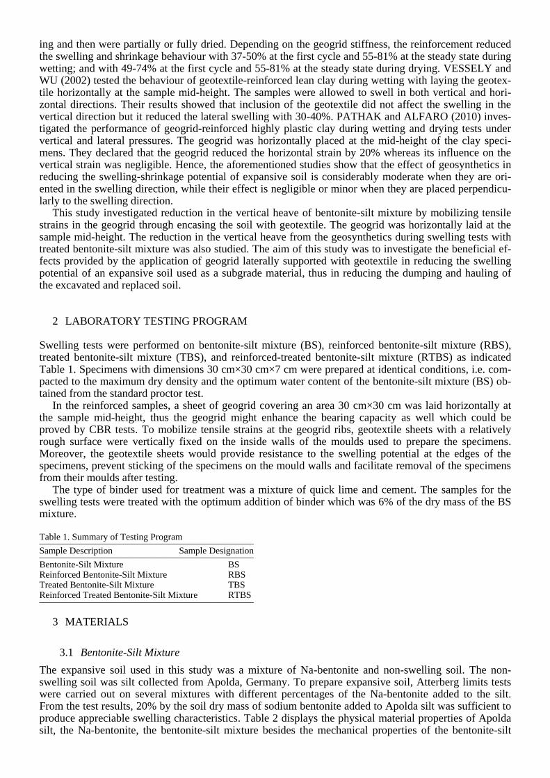
base plates of the moulds were perforated to allow water access to the specimens during wetting. Geotex-tile sheets were fixed on all the inner walls of the mould to serve as encasement as well as lubricant. The specimens were prepared with a size of 30 cm×30 cm×7 cm; they were compacted manually in two equal layers each with a height of 3.5 cm. The compaction was achieved with a hammer onto a plastic plate with dimensions 29.5 cm×29.5 cm×1 cm laid above the soil at the layer to be compacted (Fig. 1-b), thereafter the plastic plate was removed and the compaction process was accomplished with a metal rammer similar to that of the standard proctor with a 5 cm×5 cm cubic face and a mass of 2.5 kg falling directly on the soil. In the reinforced samples, a sheet of geogrid with the same internal dimensions of the mould was located at the sample mid-height.
5 TEST PROCEDURE
After sample preparation, each specimen individually was laid in a plastic container. A perforated poly-propylene plate with dimensions 29 cm×29 cm×1 cm was placed on the top of each specimen to allow water access to the specimen from the top, to decrease the moisture loss from the specimen due to evapo-ration during the swelling test and to serve as a stand for fixing the dial gauge used for measuring the ver-tical increase in the sample height. The specimens were then inundated with water from top and bottom and the testing setups were covered with plastic wraps to provide further protection against evaporation thus the specimens remain underwater during the whole test (Fig. 1-c). The dial gauge readings were fre-quently recorded until the end of the swelling tests; afterwards the specimens were lifted up from water and were allowed to drain downwards. Finally, samples for water content determination were taken from each specimen.
Figure 1. Preparation of a Reinforced Sample & Test Setup.
6 TEST RESULTS AND DISCUSSION
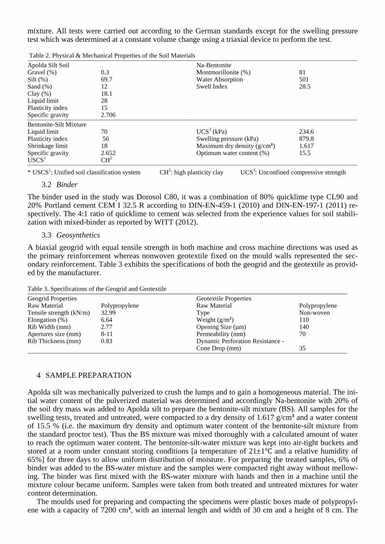
The results of the swelling potential for the different tested samples obtained from the swelling tests are displayed at Figure 2 and Table 4. The maximum swelling potential was obtained from the bentonite-silt mixture BS while the minimum swelling potential occurred at the treated bentonite-silt mixture (TBS). Presence of the geogrid in the reinforced bentonite-silt mixture (RBS) reduced the swelling potential con-siderably where its presence in the reinforced-treated bentonite-silt mixture (RTBS) caused a slight in-crease in the swelling potential in comparison to that of the TBS sample.
The intended swelling potential is the percent increase at the sample height divided by its initial height. The efficiency of the stabilizer thus could be determined as the percent decrease in the swelling potential produced by the stabilizer with respect to that of the bentonite-silt mixture.
Presence of the geotextile supposed to have the same effects in all samples as it was the same material. Hence, due to comparison between the specimens, the major differences at the swelling potential of the specimens referred to presence of the geogrid as discussed below.
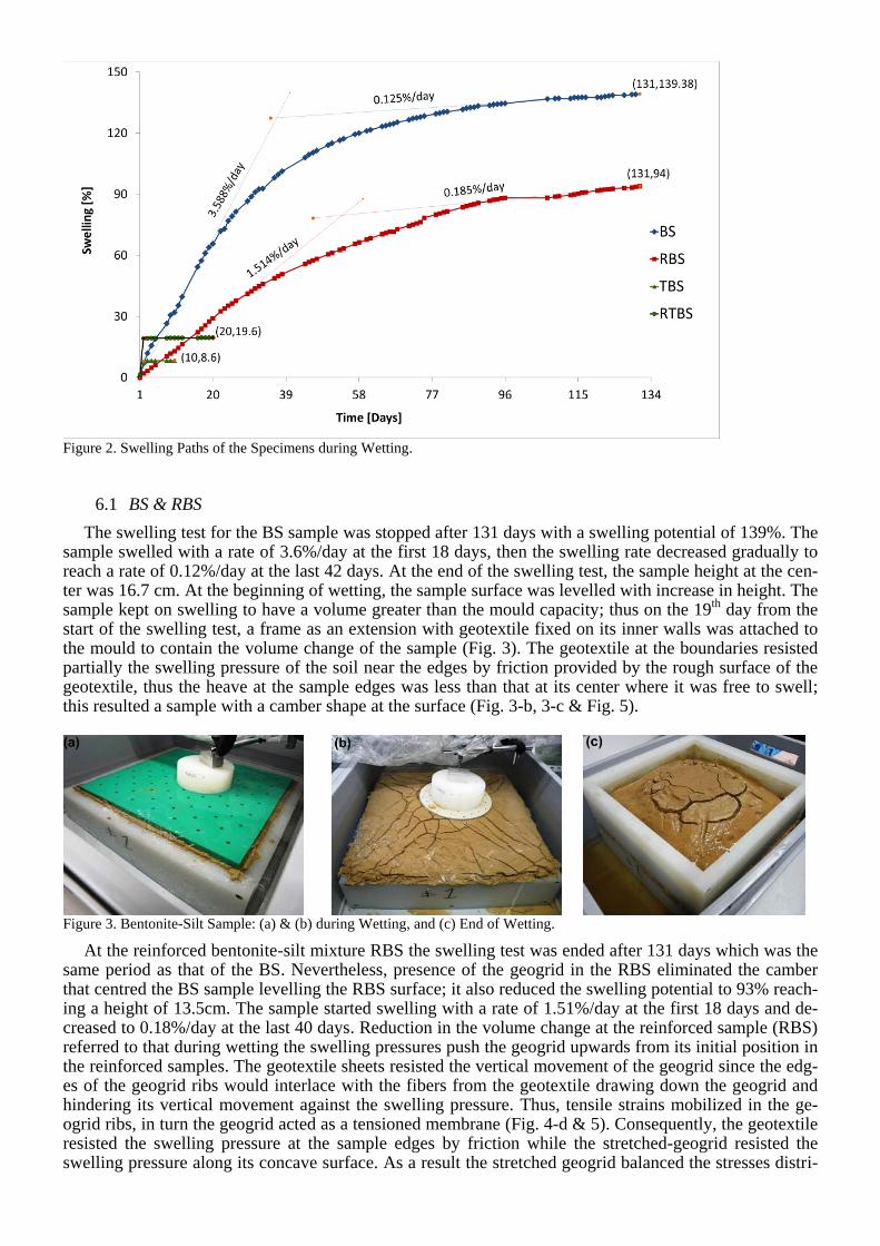
Figure 2. Swelling Paths of the Specimens during Wetting.
6.1 BS & RBS
The swelling test for the BS sample was stopped after 131 days with a swelling potential of 139%. The sample swelled with a rate of 3.6%/day at the first 18 days, then the swelling rate decreased gradually to reach a rate of 0.12%/day at the last 42 days. At the end of the swelling test, the sample height at the cen-ter was 16.7 cm. At the beginning of wetting, the sample surface was levelled with increase in height. The sample kept on swelling to have a volume greater than the mould capacity; thus on the 19
th day from the
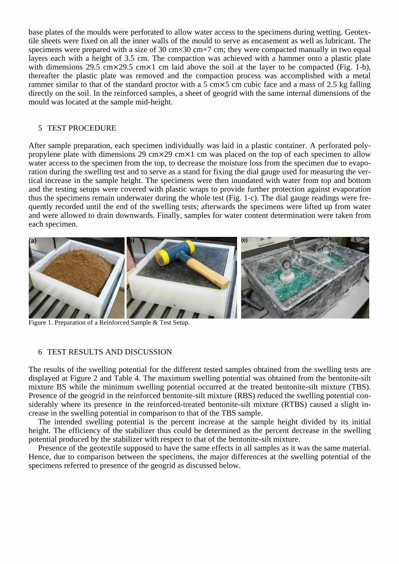
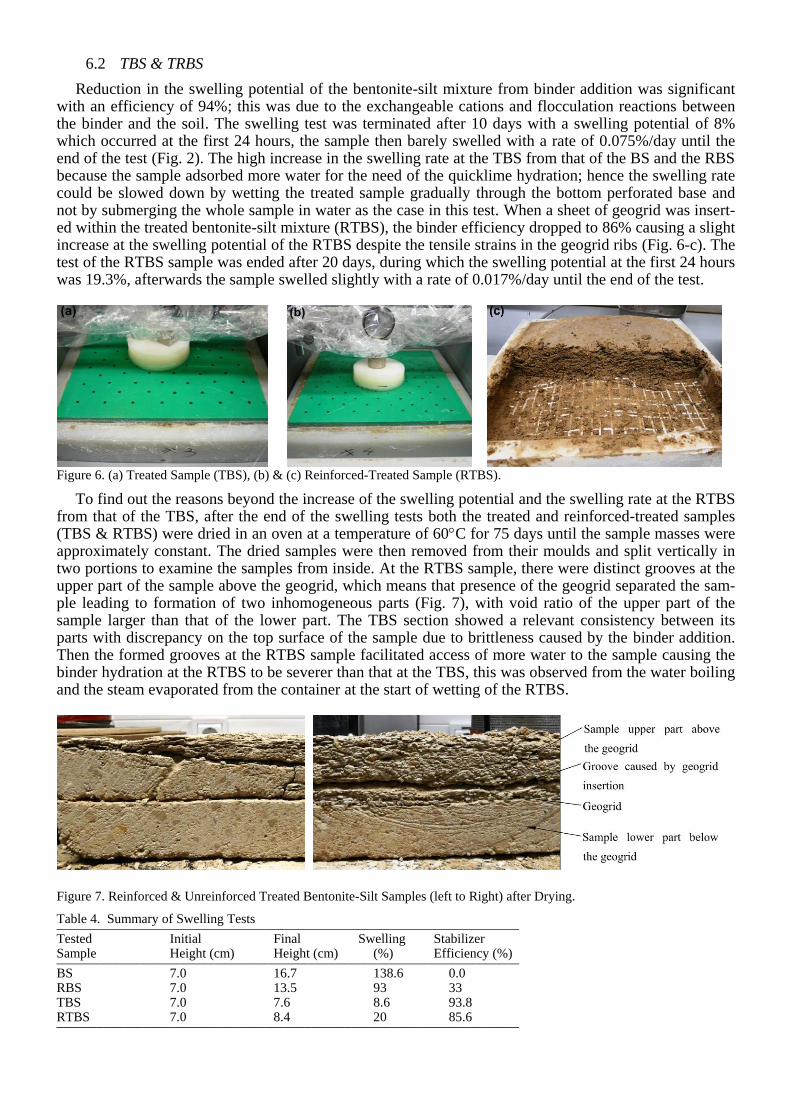
start of the swelling test, a frame as an extension with geotextile fixed on its inner walls was attached to the mould to contain the volume change of the sample (Fig. 3). The geotextile at the boundaries resisted partially the swelling pressure of the soil near the edges by friction provided by the rough surface of the geotextile, thus the heave at the sample edges was less than that at its center where it was free to swell; this resulted a sample with a camber shape at the surface (Fig. 3-b, 3-c & Fig. 5).
Figure 3. Bentonite-Silt Sample: (a) & (b) during Wetting, and (c) End of Wetting.
At the reinforced bentonite-silt mixture RBS the swelling test was ended after 131 days which was the same period as that of the BS. Nevertheless, presence of the geogrid in the RBS eliminated the camber that centred the BS sample levelling the RBS surface; it also reduced the swelling potential to 93% reach-ing a height of 13.5cm. The sample started swelling with a rate of 1.51%/day at the first 18 days and de-creased to 0.18%/day at the last 40 days. Reduction in the volume change at the reinforced sample (RBS) referred to that during wetting the swelling pressures push the geogrid upwards from its initial position in the reinforced samples. The geotextile sheets resisted the vertical movement of the geogrid since the edg-es of the geogrid ribs would interlace with the fibers from the geotextile drawing down the geogrid and hindering its vertical movement against the swelling pressure. Thus, tensile strains mobilized in the ge-ogrid ribs, in turn the geogrid acted as a tensioned membrane (Fig. 4-d & 5). Consequently, the geotextile resisted the swelling pressure at the sample edges by friction while the stretched-geogrid resisted the swelling pressure along its concave surface. As a result the stretched geogrid balanced the stresses distri-
bution within the reinforced sample and reduced the swelling pressure transferred to the upper layer above the geogrid; this led to reduction in the total heave and slowing down the swelling rate (Fig. 2). Furthermore, there might be a contribution in restraining the swelling potential at least at the first stage of wetting from the adhesive bonds between the geogrid-soil and the soil-soil at both sides of the geogrid which diminished with increase in the water content.
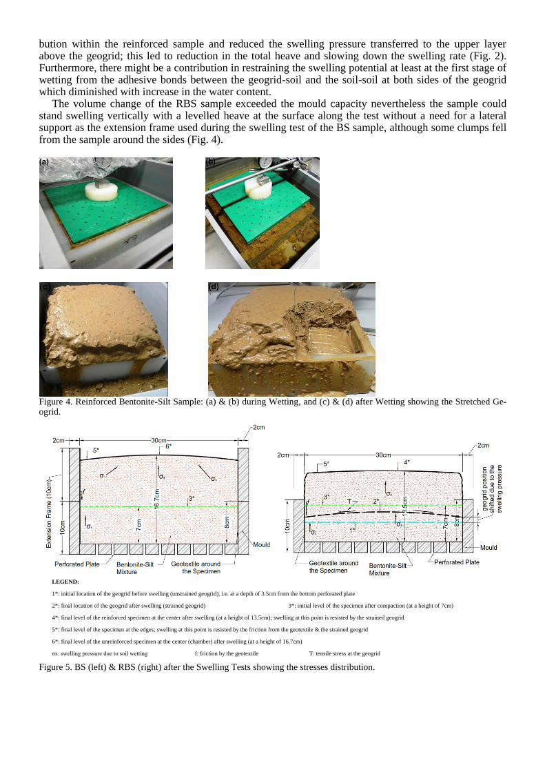
The volume change of the RBS sample exceeded the mould capacity nevertheless the sample could stand swelling vertically with a levelled heave at the surface along the test without a need for a lateral support as the extension frame used during the swelling test of the BS sample, although some clumps fell from the sample around the sides (Fig. 4).
Figure 4. Reinforced Bentonite-Silt Sample: (a) & (b) during Wetting, and (c) & (d) after Wetting showing the Stretched Ge-ogrid.
LEGEND:
1*: initial location of the geogrid before swelling (unstrained geogrid), i.e. at a depth of 3.5cm from the bottom perforated plate
2*: final location of the geogrid after swelling (strained geogrid) 3*: initial level of the specimen after compaction (at a height of 7cm)
4*: final level of the reinforced specimen at the center after swelling (at a height of 13.5cm); swelling at this point is resisted by the strained geogrid
5*: final level of the specimen at the edges; swelling at this point is resisted by the friction from the geotextile & the strained geogrid
6*: final level of the unreinforced specimen at the center (chamber) after swelling (at a height of 16.7cm)
σs: swelling pressure due to soil wetting f: friction by the geotextile Ƭ: tensile stress at the geogrid
Figure 5. BS (left) & RBS (right) after the Swelling Tests showing the stresses distribution.
6.2 TBS & TRBS
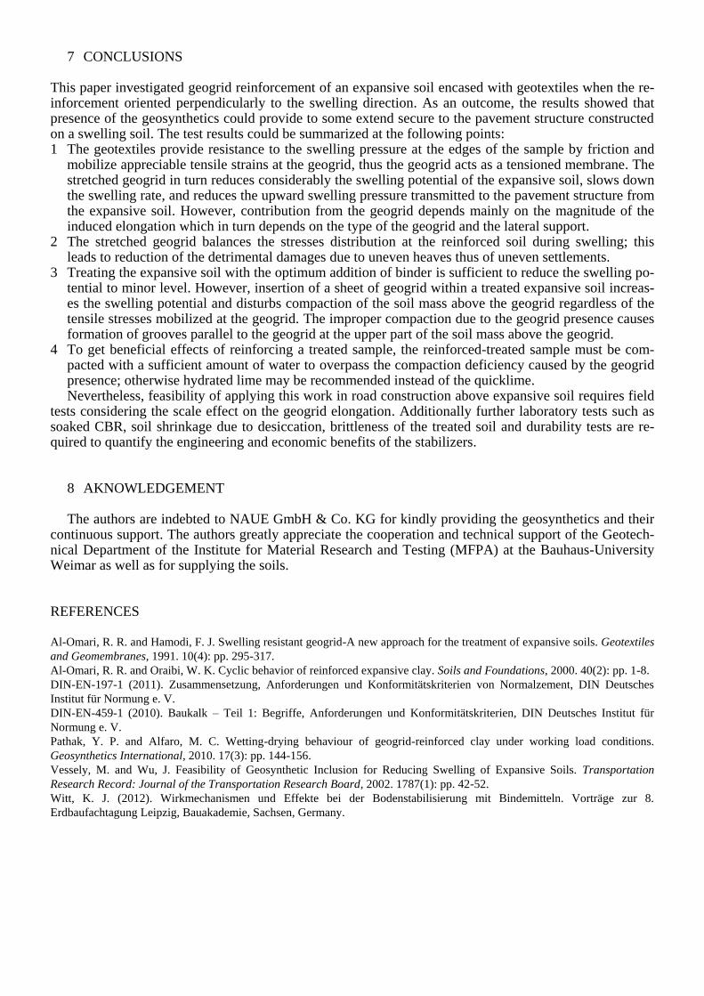
Reduction in the swelling potential of the bentonite-silt mixture from binder addition was significant with an efficiency of 94%; this was due to the exchangeable cations and flocculation reactions between the binder and the soil. The swelling test was terminated after 10 days with a swelling potential of 8% which occurred at the first 24 hours, the sample then barely swelled with a rate of 0.075%/day until the end of the test (Fig. 2). The high increase in the swelling rate at the TBS from that of the BS and the RBS because the sample adsorbed more water for the need of the quicklime hydration; hence the swelling rate could be slowed down by wetting the treated sample gradually through the bottom perforated base and not by submerging the whole sample in water as the case in this test. When a sheet of geogrid was insert-ed within the treated bentonite-silt mixture (RTBS), the binder efficiency dropped to 86% causing a slight increase at the swelling potential of the RTBS despite the tensile strains in the geogrid ribs (Fig. 6-c). The test of the RTBS sample was ended after 20 days, during which the swelling potential at the first 24 hours was 19.3%, afterwards the sample swelled slightly with a rate of 0.017%/day until the end of the test.
Figure 6. (a) Treated Sample (TBS), (b) & (c) Reinforced-Treated Sample (RTBS).
To find out the reasons beyond the increase of the swelling potential and the swelling rate at the RTBS from that of the TBS, after the end of the swelling tests both the treated and reinforced-treated samples (TBS & RTBS) were dried in an oven at a temperature of 60C for 75 days until the sample masses were approximately constant. The dried samples were then removed from their moulds and split vertically in two portions to examine the samples from inside. At the RTBS sample, there were distinct grooves at the upper part of the sample above the geogrid, which means that presence of the geogrid separated the sam-ple leading to formation of two inhomogeneous parts (Fig. 7), with void ratio of the upper part of the sample larger than that of the lower part. The TBS section showed a relevant consistency between its parts with discrepancy on the top surface of the sample due to brittleness caused by the binder addition. Then the formed grooves at the RTBS sample facilitated access of more water to the sample causing the binder hydration at the RTBS to be severer than that at the TBS, this was observed from the water boiling and the steam evaporated from the container at the start of wetting of the RTBS.
Figure 7. Reinforced & Unreinforced Treated Bentonite-Silt Samples (left to Right) after Drying.
Table 4. Summary of Swelling Tests _____________________________________________________________________ Tested Initial Final Swelling Stabilizer Sample Height (cm) Height (cm) (%) Efficiency (%) _____________________________________________________________________ BS 7.0 16.7 138.6 0.0 RBS 7.0 13.5 93 33 TBS 7.0 7.6 8.6 93.8 RTBS 7.0 8.4 20 85.6 _____________________________________________________________________
7 CONCLUSIONS
This paper investigated geogrid reinforcement of an expansive soil encased with geotextiles when the re-inforcement oriented perpendicularly to the swelling direction. As an outcome, the results showed that presence of the geosynthetics could provide to some extend secure to the pavement structure constructed on a swelling soil. The test results could be summarized at the following points: 1 The geotextiles provide resistance to the swelling pressure at the edges of the sample by friction and
mobilize appreciable tensile strains at the geogrid, thus the geogrid acts as a tensioned membrane. The stretched geogrid in turn reduces considerably the swelling potential of the expansive soil, slows down the swelling rate, and reduces the upward swelling pressure transmitted to the pavement structure from the expansive soil. However, contribution from the geogrid depends mainly on the magnitude of the induced elongation which in turn depends on the type of the geogrid and the lateral support.
2 The stretched geogrid balances the stresses distribution at the reinforced soil during swelling; this leads to reduction of the detrimental damages due to uneven heaves thus of uneven settlements.
3 Treating the expansive soil with the optimum addition of binder is sufficient to reduce the swelling po-tential to minor level. However, insertion of a sheet of geogrid within a treated expansive soil increas-es the swelling potential and disturbs compaction of the soil mass above the geogrid regardless of the tensile stresses mobilized at the geogrid. The improper compaction due to the geogrid presence causes formation of grooves parallel to the geogrid at the upper part of the soil mass above the geogrid.
4 To get beneficial effects of reinforcing a treated sample, the reinforced-treated sample must be com-pacted with a sufficient amount of water to overpass the compaction deficiency caused by the geogrid presence; otherwise hydrated lime may be recommended instead of the quicklime. Nevertheless, feasibility of applying this work in road construction above expansive soil requires field
tests considering the scale effect on the geogrid elongation. Additionally further laboratory tests such as soaked CBR, soil shrinkage due to desiccation, brittleness of the treated soil and durability tests are re-quired to quantify the engineering and economic benefits of the stabilizers.
8 AKNOWLEDGEMENT
The authors are indebted to NAUE GmbH & Co. KG for kindly providing the geosynthetics and their continuous support. The authors greatly appreciate the cooperation and technical support of the Geotech-nical Department of the Institute for Material Research and Testing (MFPA) at the Bauhaus-University Weimar as well as for supplying the soils.
REFERENCES
Al-Omari, R. R. and Hamodi, F. J. Swelling resistant geogrid-A new approach for the treatment of expansive soils. Geotextiles
and Geomembranes, 1991. 10(4): pp. 295-317.
Al-Omari, R. R. and Oraibi, W. K. Cyclic behavior of reinforced expansive clay. Soils and Foundations, 2000. 40(2): pp. 1-8.
DIN-EN-197-1 (2011). Zusammensetzung, Anforderungen und Konformitätskriterien von Normalzement, DIN Deutsches
Institut für Normung e. V.
DIN-EN-459-1 (2010). Baukalk – Teil 1: Begriffe, Anforderungen und Konformitätskriterien, DIN Deutsches Institut für
Normung e. V.
Pathak, Y. P. and Alfaro, M. C. Wetting-drying behaviour of geogrid-reinforced clay under working load conditions.
Geosynthetics International, 2010. 17(3): pp. 144-156.
Vessely, M. and Wu, J. Feasibility of Geosynthetic Inclusion for Reducing Swelling of Expansive Soils. Transportation
Research Record: Journal of the Transportation Research Board, 2002. 1787(1): pp. 42-52.
Witt, K. J. (2012). Wirkmechanismen und Effekte bei der Bodenstabilisierung mit Bindemitteln. Vorträge zur 8.
Erdbaufachtagung Leipzig, Bauakademie, Sachsen, Germany.