Embed Size (px)
Citation preview

Generic Unit
Installation Manual
Spray Height Controller
Improving the competitiveness of Industry and
Agriculture through Precision Measurement

Printed in Canada
Copyright 2008 by NORAC Systems International Inc.
Reorder P/N: UC4+BC+AN2-INST Rev E (Generic Unit)
NOTICE NORAC Systems International Inc. reserves the right to improve products and their specifications without notice and without the
requirement to update products sold previously. Every effort has been made to ensure the accuracy of the information contained in this manual. The technical information in this manual was reviewed at the time of approval for publication.
TABLE OF CONTENTS
1 INTRODUCTION.................................................................................................................................. 1
2 GENERAL SYSTEM DESCRIPTION .................................................................................................. 2
3 PARTS LISTS ...................................................................................................................................... 3
4 INSTALLATION PROCEDURE ........................................................................................................... 6
4.1 DETERMINING THE STYLE OF INSTALLATION .................................................................................... 6 4.1.1 Electrically Teed Installation.................................................................................................... 6 4.1.2 Hydraulically Teed Installation................................................................................................. 9
4.2 EXISTING SYSTEM CHECK ............................................................................................................. 12 4.3 BOOM SPEED TEST...................................................................................................................... 12 4.4 WING SENSOR INSTALLATION....................................................................................................... 14 4.5 MAIN LIFT SENSOR INSTALLATION ................................................................................................ 17 4.6 ROLL SENSOR INSTALLATION ....................................................................................................... 18
4.6.1 Trapeze Style Roll Sensor Installation .................................................................................. 19 4.6.2 Center Pivot Style boom Roll Sensor Installation.................................................................. 22 4.6.3 Inverted Roll Sensor Mounting .............................................................................................. 24 4.6.4 Temperature probe................................................................................................................ 24
4.7 HYDRAULIC INSTALLATION ........................................................................................................... 25 4.7.1 Valve Assembly ..................................................................................................................... 25 4.7.2 Valve Mounting...................................................................................................................... 27 4.7.3 Hydraulic Plumbing – Electrically Teed................................................................................. 28 4.7.4 Hydraulic Plumbing – Hydraulically Teed.............................................................................. 28
4.8 ELECTRICAL INSTALLATION .......................................................................................................... 29 4.8.1 Cable Installation: Electrically teed Installation ..................................................................... 33 4.8.2 Cable Installation: Hydraulically Teed Installation................................................................. 36
4.9 COMPLETING THE INSTALLATION .................................................................................................. 37
5 ELECTRICAL REFERENCE – CABLE DRAWINGS........................................................................ 38
5.1 ITEM C2: 44668 – SENSOR BRANCH CABLE ................................................................................. 38 5.2 ITEM C02B: 44664 – CABLE UC4 CAN NODE DUAL .................................................................... 38 5.3 ITEM C3: 44656D – CABLE VALVE VARIABLE RATE DT................................................................ 39 5.4 ITEM C10: 44658-39 – POWER CABLE GENERIC SELF – PROPELLED............................................ 40 5.5 ITEM C11: 44651-03 – EXTENSION CABLE VALVE GENERIC ......................................................... 41 5.6 ITEM C12A: 44658-35 - VALVE INTERFACE CABLE PIGTAIL .......................................................... 42 5.7 ITEM C12B: 44658-36 – WING/BYPASS INTERFACE CABLE .......................................................... 43 5.8 ITEM C13: 44658-37: VALVE INTERFACE CABLE MAIN LIFT ONLY ................................................. 44 5.9 ITEM C15: 44658-31 – HAND CONTROL INTERFACE CABLE .......................................................... 45

1
1 INTRODUCTION
Congratulations on your purchase of the NORAC UC4+ Spray Height Controller. This system is
manufactured with top quality components and is engineered using the latest technology to
provide operating features and reliability unmatched for years to come.
When properly used the system can provide protection from sprayer boom damage, improve
sprayer efficiency, and ensure chemicals are applied correctly.
Please take the time to read this manual completely before attempting to install the system. A
thorough understanding of this manual will ensure that you receive the maximum benefit from
the system.
YOUR INPUT CAN HELP MAKE US BETTER! If you find issues or have suggestions
regarding the parts list or the installation procedure, please don’t hesitate to contact us via
the information given below:
Phone: 1-800-667-3921 Canada (Toll Free)
1-866-306-6722 United States (Toll Free)
(+33) 06 03 87 80 78 Europe
1-306-664-6711 all other regions
E-mail: [email protected]
Website: www.norac.ca

2
2 GENERAL SYSTEM DESCRIPTION
Figure 1 depicts the general system layout of the UC4+ Spray Height Control system.
Figure 1 – System Components and General Location
NOTICE:
Every effort has been made to ensure the
accuracy of the information contained in this
manual. All parts supplied are selected
specially to fit the sprayer to facilitate a
complete installation. However, NORAC
cannot guarantee all parts fit as intended due
to the variations of the sprayer by the
manufacturer. Please read this manual in
its entirety before attempting installation.
ATTENTION:
When installing the UC4+ Spray Height
Control system please be aware that at a
point in the installation your sprayer booms
will be inoperative until the installation is
complete. Any installation procedure
requiring boom movement will need to be
done first. Once the hydraulics have been
disconnected you must complete the
electrical installation before the booms
become operative.

3
3 PARTS LISTS
The parts that come with your UC4+ Spray Height Control system are listed in Table 1. The item
number on the left side of this table references each part.
Please ensure that all parts in your kit are present before proceeding with your installation.
Table 1 – Sprayer Boom Control System Parts
Item Part Number Name Quantity
B05 44706-01 KIT CABLE TIE BLACK 10 PCS 21 IN 150 PCS 7.5 IN 1
B10 44700-06 BRACKET VALVE MOUNTING STD 1
B11 44743 MOUNTING BRACKET MAIN LIFT SENSOR UC4 PLUS 1
B13 44728 MOUNTING BRACKET COMPLETE UC4 BREAKAWAY EXTENDED 2
C02 44668 CABLE UC3 SENSOR BRANCH 1 AMP RECEPT 3 AMP PLUG BC 1
C02B 44664 CABLE UC4 CAN NODE DUAL 1
C03 44656D CABLE VALVE VARIABLE RATE DT 1
C10 44650-39 CABLE POWER GENERIC SELF-PROPELLED 1
C11 44651-03 CABLE EXTENSION VALVE GENERIC 1
C12A 44658-35 INTERFACE CABLE UC4 C12A GENERIC GND2 1
C12B 44658-36 INTERFACE CABLE WINGS UC4 C12B GENERIC GND2 1
C13 44658-37 INTERFACE CABLE MAIN UC4 C13 GENERIC GND2 1
C15 44658-31 CABLE INTERFACE UC4 BC C15 HAND CONTROL PIGTAIL 1
E01 4461BC+ UC4 PLUS BOOM CONTROL PANEL 1
E02 44631 UC4 ULTRASOUND SENSOR 3
E03 44641 UC4 PLUS ROLL SENSOR W TEMPERATURE PROBE 1
E04 44642 UC4 PLUS ROLL SENSOR 1
H01 44865-01 HYDRAULICS FITTING KIT - AN2 1
M01 446BC+MAN7 OPERATOR MANUAL UC4+ SPRAY HEIGHT CONTROL 1
M10 UC4+BC+AN2-INST MANUAL INSTALLATION UC4+ GENERIC KIT 1
V01* 44963D VALVE BLOCK ASSEMBLY 2 STATION CC/LS PROP DT 4 BOLT 1
4
Substitution parts will in no way affect the operation of the system provided that they are installed
as directed.
* Item V01 – 2 Station Valve Block (44963D) may be substituted with:
Item Part Number Name Quantity
V01 44933D VALVE BLOCK ASSEM UC4-BC 2-STATION CC/LS VARIABLE RATE 1
The 44933D is a direct replacement for the 44963D. Both valve blocks function the same. The blocks
are identifiable by the filter cap shape and by the part number stamped on the side.
The A and B ports are opposite on each valve block so verify that the hoses are being connected to
the correct port. The raise lines always go to the “B” port and the lower lines go to the “A” port.
44933D Valve Block Shown Alongside 44963D Valve Block
Filter Cap Part Number
(44933D) Filter Cap Part Number
(44963D)

5
Table 2 - 44865-01 - Hydraulics Fittings Kit Details
Item Part Number Name Quantity Picture
F07 103312 MALE ADAPTER - 6MB-6MJ 6
F08 44928 ORIFICE INSERT .047 IN ONE WAY 4
F09 104369 PLUG - 6MBP 2
6 M B - 6 M OR X 90SIZE IN
1/16TH'SGENDER: MALE
OR FEMALE
90° ANGLESWIVEL
TYPE
GENDER
SIZE
TYPE:
B - ORB
J - JIC
OR - FLAT
FACE
P - PIPE
Fitting Name
Example:
The use of dielectric grease is not recommended on any NORAC electrical connections.
To ensure all stainless steel hardware does not gall or seize apply a light coating of the supplied
Permatex Anti-seize grease to all threaded parts upon installation. Permatex Anti-seize lubricant is
preferred, but other similar anti-seize products may be used.
6
4 INSTALLATION PROCEDURE
4.1 DETERMINING THE STYLE OF
INSTALLATION
In general, there are two styles of
installation that can be done with the
NORAC UC4+ Spray Height Control
system System: Electrically Teed
Installation and Hydraulically Teed
Installation.
4.1.1 Electrically Teed Installation
Electrically Teed Installation is the preferred
style of installation. However, this style can
be done only if the sprayer valve block has
individual electrical wiring to control each
boom function (e.g. left up, left down, right
up, right down, main up, and main down).
Figure 2 – Electrical Wiring Applicable
for Electrically Teed Installation
Figure 3 and Figure 4 show the
Electrically Teed installation in its
general installation configuration.

7
Figure 3 – UC4+ BC Components: Electrically Teed Installation

8
Figure 4 – Hydraulic Components: Electrically Teed Installation
9
4.1.2 Hydraulically Teed Installation
Hydraulically Teed Installation must be
done if the sprayer valve block does NOT
have individual electrical wiring to control
each boom function. For example, your
sprayer may have signal lines to select a
boom (left, right and main) and separate
electrical signals for the direction (up and
down).
Figure 5 – Typical Electrical Wiring for
which Hydraulically Teed Installation is
Required
For Hydraulically Teed Installation,
MANUAL mode of the UC4+ Control
System does not operate the same as with
Electrically Teed Installation. Electrically
Teed Installation will allow the operator to
trigger individual boom movements into
MANUAL mode while maintaining AUTO
mode for the other boom movements (e.g.
left boom can be in MANUAL mode while
right boom is still in AUTO mode).
Hydraulically Teed Installation does not
support this function. If the operator
triggers any boom movement, the whole
NORAC system will convert to MANUAL
mode.
Hydraulically Teed Installation
may also be done if the operator
wants the existing sprayer valves,
instead of the NORAC valves, to
operate the booms when the
NORAC system is in MANUAL
mode.
Figure 6 and Figure 7 show the
Hydraulically Teed Installation in
its general installation
configuration.
10
Figure 6 – UC4+ BC Components: Hydraulically Teed Installation
11
Figure 7 – Hydraulic Components: Hydraulically Teed Installation
12
4.2 EXISTING SYSTEM CHECK
It is necessary to check the existing system’s
functionality before installing the UC4+
Spray Height Control system.
1. Drive your sprayer onto a flat piece of
land, with unobstructed boom movement
(e.g. no power lines).
2. Test that all boom functions operate
correctly. As you test each function
check it off in Table 3.
It is necessary to test the boom
functions in all directions
Table 3 – Hydraulic System Function
Check Sheet
BOOM
FOLD
IN
FOLD
OUT UP DOWN
LEFT
MAIN
RIGHT
ROLL* N/A N/A
* Some sprayers may not have this function.
4.3 BOOM SPEED TEST
IMPORTANT:
Raise/lower all boom sections several
times to warm up the hydraulic system.
Grease all moving parts for consistent
results.
1. Lower each boom and main section as
close to the ground as possible.
2. Set your sprayer at field working RPM
on the throttle and mark this value in
Table 4.
You will need a stopwatch or a
watch that displays “seconds” for
the next step.
3. Raise the LEFT boom from its extreme
LOW position to the very TOP of its
travel. Record the time this takes in
Table 4, “Trial #1” for “Left UP”.
4. Lower the LEFT boom from its extreme
HIGH position to the BOTTOM of its
travel. Record this time in Table 4,
Trial #1, for “Left DOWN”.
Be careful when lowering the
booms so they don’t hit the
ground.
5. Similarly, record two more time trials
(Trial #2 & #3) for the LEFT boom and
record in Table 4
6. Repeat Steps 1 through 5 for the RIGHT,
MAIN and ROLL functions.
Your sprayer may not have a roll
feature.
7. Average the three trials recorded for
each boom movement and record this
calculation in the “Average Time” slot in
Table 4.
8. These “Average Times” now represent
how quickly your system can react to
manual control. In Section 1.1, this
procedure is repeated with the UC4+
Spray Height Control system installed
for comparison and troubleshooting
purposes.

13
Table 4 – Boom Test Record (WITHOUT UC4+ Spray Height Control system)
Working RPM:
Boom Trial #1
[Sec]
Trial #2
[Sec]
Trial #3
[Sec]
Avg Time
[Sec]
Left UP
Left DOWN
Right UP
Right Down
Main UP
Main DOWN
Roll CW
Roll CCW
Table 5 – Boom Test Record (WITH UC4+ Spray Height Control system)
Working RPM:
Boom Trial #1
[Sec]
Trial #2
[Sec]
Trial #3
[Sec]
Avg Time
[Sec]
Left UP
Left DOWN
Right UP
Right Down
Main UP
Main DOWN
Roll CW
Roll CCW

14
4.4 WING SENSOR INSTALLATION
1. Assemble the Breakaway Sensor
Mounting Brackets (B11) as show in
Figure 8 and Figure 9.
Figure 8 – Breakaway Sensor Bracket
Exploded View
Figure 9 – Breakaway Sensor Mounting
Bracket Assembly
To assemble the breakaway sensor
bracket:
a) Assemble the bolt and nut into the
collar.
b) Grease the bottom edge of the collar
and the angled tube of the base.
c) Place the collar onto the angled tube
of the mounting base.
d) Install the spring between the collar
and the upper ring of the base.
e) Insert tube through assembly and
tighten the collar
2. Mount the sensor bracket onto the boom.
If possible, mount the sensor
brackets while the booms are in
their folded position to ensure that
they will not interfere with
anything when the boom is folded
for transport.
3. The sensor mounting brackets can be
installed with the mounting base behind
(Figure 12) or in front of the tube
(Figure 10).
Mounting the sensor bracket to
the break-away section of the
boom may cause the boom to drop
suddenly as a break-away occurs.
This will occur on break-away
sections which lift as they break
away.
For optimal boom tip protection, it
is recommended that the sensor be
mounted within approximately
two feet (60cm) of the boom tip.
Please refer to the UC4+ Spray Height
Control system warranty at the end of
the UC4+ Sprayer Boom Control
Operator’s Manual (M01) for
implications.
4. Mount the NORAC UC4+ ultrasonic
sensor (E02) into the sensor brackets.
The sensors should be oriented forward
(ahead) of the boom (see Figure 10 and
Figure 12).
When installing the UC4+ sensors
(E02), start with the smallest serial

15
number on the left hand side
proceeding to the largest serial
number on the right hand side
(Figure 13).
5. Sensor cables should run through the
mounting bracket tube and then behind
the member the bracket is mounted onto.
Cable-tie the connector in place. The
cable must not be allowed to hang below
the boom (Figure 10).
Figure 10 – Another Acceptable
Mounting
Avoid mounting sensors in
locations where they may read
from parts of the boom as shown
in Figure 11.
Figure 11 – Poor Mounting
(Sensor reading off boom)
General mounting rules for UC4+
ultrasonic wing sensors:
a) In its lowest position, the sensor mouth
must be 9 inches or more from the
ground.
b) The bottom of the sensor must be at least
9 inches in front of the spray nozzles.
c) The bottom of the sensor must be at least
9 inches above the spray nozzles.
d) Ensure that there are no obstructions
within a 12-inch diameter circle
projected directly below the center of the
sensor.
e) The sensor should be approximately
vertical at normal operating heights.
Figure 12 – Sensor Mounting Guidelines
A B
B
D
C
Ultrasonic
Acoustic Cone

16
Figure 13 – Sensor Serial Number Installation Location
3 SENSOR SYSTEM
5 SENSOR SYSTEM

17
4.5 MAIN LIFT SENSOR INSTALLATION
1. Assemble the main lift sensor bracket
(B11) as shown in Figure 14.
Figure 14 – Main Lift Sensor Bracket
2. The bracket can then be mounted to the
lowest frame member on the center
section of the sprayer. The bracket
should be mounted so the sensor
mounting collar is in approximately the
center of the sprayer and ahead of the
boom (Figure 15 and Figure 16).
The sensor mounting collar must
not be behind the sprayer’s wheel.
The General Mounting Rules for
UC4+ Ultrasonic Sensors, from the
previous section, must be followed.
Figure 15 – Main Lift Sensor Bracket
Mounting Position
3. Mount the sensor onto the sensor
mounting collar (Figure 15).
Figure 16 – Main Lift Sensor Mounted in
the Correct Location
Bracket Tube
Sensor
Mounting Tab
Sensor Mounting
Collar
Bracket Base

18
4.6 ROLL SENSOR INSTALLATION
Mount the roll sensors to the included
roll sensor brackets using the machine
screws and nylon lock nuts, as illustrated
in Figure 17.
The roll sensors must be mounted
tightly to the brackets.
If your sprayer is a trapeze style
pivoting boom (the boom hangs
from two link arms) then follow
Section 4.6.1 to install the roll
sensors.
If your sprayer is a center pin
pivoting boom (the boom pivots on
a pin in the center of the boom)
then follow Section 4.6.2 to install
the roll sensors.
Sometimes it best to mount the roll
sensors in an inverted orientation
(upside down). For this type of
mounting refer to Section 4.6.3.
Figure 17 - Mounting the Roll Sensor to
the Roll Sensor Mounting Bracket
Figure 18 - Roll Sensor Mounting with Respect to Sprayer Orientation
* The boom frame
roll sensor does not
have a temperature
probe
19
4.6.1 Trapeze Style Roll Sensor Installation
This section is only for trapeze
style booms (booms that hang
from link arms. If your sprayer
has a center pivot boom proceed to
Section 4.6.2.
When mounting the roll sensors, use the
following guidelines and refer to Figure 19.
a) The smaller the distance between A and
B in Figure 19, the better the
performance will be.
b) Ensure the roll sensors are sitting
relatively level when the sprayer chassis
and booms are level.
c) Both roll sensors must be mounted with
the circular AMP connector facing
towards the Right-Hand Wing (when
looking from the rear of the sprayer).
Figure 19 - General Roll Sensor Mounting Location on a Trapeze Style Boom
Connectors towards
Right-hand Wing �

20
4.6.1.1 Boom Frame Roll Sensor Mounting
1. Use the supplied hardware to mount the
boom frame roll sensor (E04) as shown
in Figure 20.
When mounting the boom frame roll sensor
follow these guidelines:
a) To prevent bending the bracket,
ensure bolts are placed as close
together as possible (minimize C in
Figure 20).
b) Be sure to use the roll sensor
without the temperature probe
(E04).
c) When the boom is centered (not
rolled over) the roll sensor should
be level with respect to the sprayer
chassis.
d) It is best to mount the roll sensor to
the left hand trapeze link (when
looking from the rear of the
sprayer).
e) The roll sensor AMP (circular)
connector MUST exit towards the
right hand wing (when looking
from the rear of the sprayer).
Figure 20 - Boom Frame Roll Sensor
Mounted to a Trapeze Link
2. Cable-tie the sensor connector to the
frame with enough slack to allow the
link to rotate.
Make sure the bracket does not
collide with any parts of the
sprayer when the boom rotates.
Also ensure there is enough slack
to allow the roll sensor to rotate.

21
4.6.1.2 Chassis Roll Sensor Mounting
1. It is often best to cable tie the chassis
roll sensor in place. When mounting the
chassis roll sensor follow the guidelines
and refer to Figure 21.
The chassis roll sensor must be
mounted on a portion of the
sprayer that does not pivot and is
as close to the boom frame roll
sensor as possible (Figure 19).
a) Make sure you are using the roll
sensor with the temperature probe
(E03).
b) Ensure the roll sensor is level with
respect to the chassis.
c) The AMP (circular) connector
MUST exit towards the right
hand wing.
d) Make sure the temperature probe is
able to reach the side of the valve
block.
Figure 21 - Chassis Roll Sensor Mounting
2. Refer to Section 4.6.4 for mounting the
temperature probe.
22
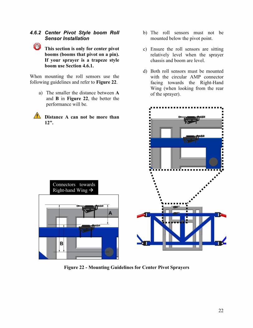
4.6.2 Center Pivot Style boom Roll Sensor Installation
This section is only for center pivot
booms (booms that pivot on a pin).
If your sprayer is a trapeze style
boom use Section 4.6.1.
When mounting the roll sensors use the
following guidelines and refer to Figure 22.
a) The smaller the distance between A
and B in Figure 22, the better the
performance will be.
Distance A can not be more than
12”.
b) The roll sensors must not be
mounted below the pivot point.
c) Ensure the roll sensors are sitting
relatively level when the sprayer
chassis and boom are level.
d) Both roll sensors must be mounted
with the circular AMP connector
facing towards the Right-Hand
Wing (when looking from the rear
of the sprayer).
Figure 22 - Mounting Guidelines for Center Pivot Sprayers
Connectors towards
Right-hand Wing �

23
4.6.2.1 Boom Roll Sensor Mounting
The boom roll sensor (E04) must be
mounted to the rotating part of the boom.
Follow these guidelines and refer to Figure
22 and Figure 24 to mount the sensor.
a) Make sure you are using the roll
sensor that does NOT have a
temperature probe (only one cable)
(E04).
b) The boom roll sensor must be
mounted to the rotating part of the
boom suspension.
c) Use cable-ties to secure the bracket
to a square edge feature (square
tube).
d) Ensure the AMP (circular)
connector exits towards the Right
Hand Wing (when looking from the
rear of the sprayer).
e) Securely cable-tie the connector to
the frame.
4.6.2.2 Chassis Roll Sensor Mounting
The chassis roll sensor must be mounted to a
non-rotating part of the boom.
a) Make sure you are mounting the roll
sensor that does have a temperature
probe (2 cables) (E03).
b) Mount the chassis roll sensor (E03)
to a non-rotating part of the boom.
c) Cable-tie the bracket to a square
edge feature (square tube).
d) The AMP (circular) connector
MUST exit towards the Right Hand
Wing (when looking from the rear).
e) Securely cable-tie the connector to
the frame.
Figure 24 - Boom and Chassis Roll Sensors Correctly Mounted
E04
E03
24
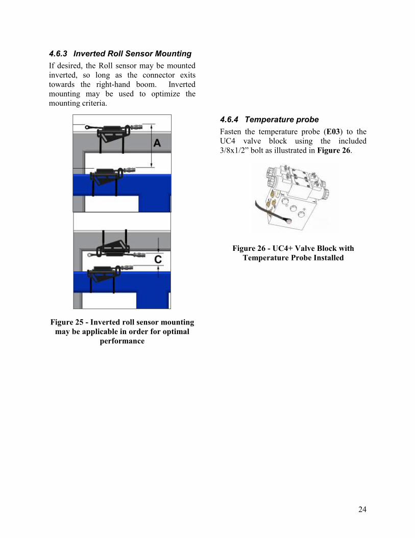
4.6.3 Inverted Roll Sensor Mounting
If desired, the Roll sensor may be mounted
inverted, so long as the connector exits
towards the right-hand boom. Inverted
mounting may be used to optimize the
mounting criteria.
Figure 25 - Inverted roll sensor mounting
may be applicable in order for optimal
performance
4.6.4 Temperature probe
Fasten the temperature probe (E03) to the
UC4 valve block using the included
3/8x1/2” bolt as illustrated in Figure 26.
Figure 26 - UC4+ Valve Block with
Temperature Probe Installed
25
4.7 HYDRAULIC INSTALLATION
WARNING!
The hydraulic system creates very high
pressure. Before disconnecting any
hydraulic lines ensure all pressure has
been bled from the system. When
changing the boom hydraulic hoses leave
the booms in TRANSPORT POSITION.
NORAC provides proportional hydraulic
valves for sprayer boom applications. For
the generic installation kit, the customer
must supply all hoses and fittings required.
The fittings (Item F07) on the NORAC
valve block are #6 MB (male ORB) to #6
MJ (male JIC). You will need the mating
female JIC fitting on your hoses. If an
adapter is required, add it after the JIC
portion of these fittings. For a typical
hydraulic layout, refer to the installation
instructions and Figure 4 and Figure 7.
IMPORTANT:
Component failure due to oil
contamination is not covered under the
UC4+ Spray Height Control system
warranty. It is recommended that a
qualified technician does the hydraulic
installation.
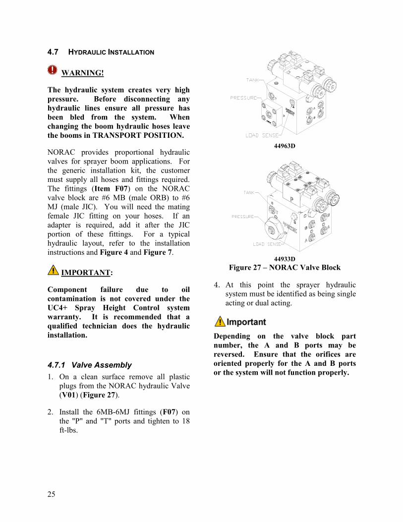
4.7.1 Valve Assembly
1. On a clean surface remove all plastic
plugs from the NORAC hydraulic Valve
(V01) (Figure 27).
2. Install the 6MB-6MJ fittings (F07) on
the "P" and "T" ports and tighten to 18
ft-lbs.
44963D
44933D
Figure 27 – NORAC Valve Block
4. At this point the sprayer hydraulic
system must be identified as being single
acting or dual acting.
Depending on the valve block part
number, the A and B ports may be
reversed. Ensure that the orifices are
oriented properly for the A and B ports
or the system will not function properly.
26
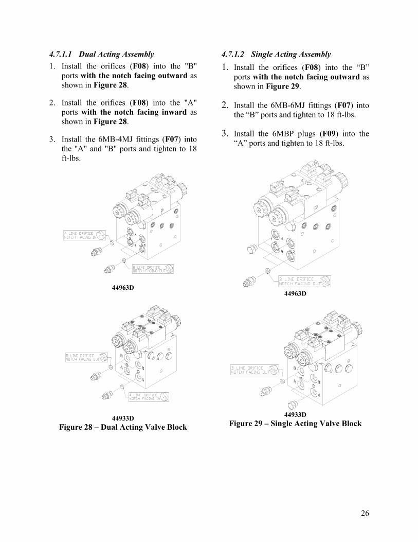
4.7.1.1 Dual Acting Assembly
1. Install the orifices (F08) into the "B"
ports with the notch facing outward as
shown in Figure 28.
2. Install the orifices (F08) into the "A"
ports with the notch facing inward as
shown in Figure 28.
3. Install the 6MB-4MJ fittings (F07) into
the "A" and "B" ports and tighten to 18
ft-lbs.
44963D
44933D
Figure 28 – Dual Acting Valve Block
4.7.1.2 Single Acting Assembly
1. Install the orifices (F08) into the “B”
ports with the notch facing outward as
shown in Figure 29.
2. Install the 6MB-6MJ fittings (F07) into
the “B” ports and tighten to 18 ft-lbs.
3. Install the 6MBP plugs (F09) into the
“A” ports and tighten to 18 ft-lbs.
44963D
44933D
Figure 29 – Single Acting Valve Block
27
4.7.2 Valve Mounting
1. Mount the NORAC valve (V01) on the
sprayer using the valve mounting
bracket (B10).
2. Thread a nut onto the short threads of
each of the threaded studs.
3. As shown in Figure 30, screw the short
side of the threaded rods into the bottom
of the valve block and tighten the hex
nuts tight to the valve block.
4. Place the valve block onto a frame
member, with the studs extending to the
other side of the member.
5. Slide the flat bar from the bracket over
the studs and install a spring washer and
nut onto each of the studs to hold the
plate in place.
6. Tighten the two nuts so the valve block
is held on tight and cannot move.
7. Cut excess off of the studs, if necessary.
If you wish to use bolts, the bolts
should thread into the valve block
at least 3/8". The valve mounting
holes are drilled and tapped 3/8
NC-1" deep. The rule of thumb for
bolt length is 1-1/2" longer than
the tube size.
You must ensure no hydraulic
components will interfere with any
sprayer parts or be pulled tight at
any time.
Figure 30 – Valve Mounting Location
28
4.7.3 Hydraulic Plumbing – Electrically Teed
WARNING!
From this point in the installation the
booms will be inoperative until the
electronics are fully installed.
1. After the NORAC valves are mounted,
the hydraulic hoses and fittings can be
plumbed. The plumbing for the
hydraulic circuit is shown schematically
in Figure 4.
2. Tee in pressure (“P”) and tank (“T”)
lines to the NORAC valve block.
3. The existing hoses that run to the boom
tilt cylinders should be disconnected
from the sprayer valve block and
reconnected to the NORAC valve block.
a) The raise lines from the boom tilt
cylinders must be connected to the
“B” ports of the NORAC valve
block. The ports on the sprayer
block must then be plugged/capped.
b) If the sprayer is Dual Acting, the
“A” ports of the NORAC block
must be connected to the “lower”
lines of the cylinders. The ports on
the sprayer block must then be
plugged/capped.
c) If the sprayer is Single Acting, the
“A” ports on the NORAC block are
plugged. The lower lines of the
cylinders can remain attached to the
sprayer valve block.
4.7.4 Hydraulic Plumbing – Hydraulically Teed
1. Follow Figure 7 to plumb the hydraulic
components.
2. Tee in the pressure (“P”) and tank (“T”)
lines to the NORAC valve block.
3. The existing hoses that run to the boom
tilt cylinders should be disconnected
from the sprayer valve block and teed
into the NORAC valve block.
4. The “raise” lines from the boom tilt
cylinders must be connected to the “B”
ports of the NORAC valve block.
a) If the sprayer is Dual Acting, the “A”
ports of the NORAC block must be
connected to the “lower” lines of the
cylinders.
b) If the sprayer is Single Acting, the
“A” ports on the NORAC block are
plugged. The “lower” lines can
remain attached to the sprayer valve
block.

29
ROP 4.8 ELECTRICAL INSTALLATION
While installing the electrical parts
of the system you may need to
refer to Section 5.
1. Install the UC4+ Control Panel (E01) in
the cab of the sprayer. Mount the panel
where it will be clearly visible and
within easy reach of the operator.
A good spot to mount the UC4+ control
panel is on the right hand side of the cab
to the Roll Over Protection Bar. Four
pilot holes for the screws provided need
to be drilled to facilitate the control
panel mounting.
Another option is to purchase an adapter
for the flexible panel mount that has a
3/8" NC threaded stud on the end to bolt
through an existing mount. You can find
these at your local outdoor store as a
RAM mount part number RAM-B-236.
(See http://www.ram-mount.com/)
Figure 31 – Control Panel Mounting
ROP

30
Figure 32 – Cable Configurations: C10 and C11
2. Connect the UC4+ power cable
(C10) to the UC4+ Control Panel in
the sprayer cab. Ensure that both
plugs (P16A and P4) are connected
to the panel (Figure 32).
Ensure the UC4+ control panel’s
power is OFF for the remaining
installation (Bottom of switch
pressed IN).
3. Connect the 3-pin AMP connector
(P3) of C10 to an auxiliary power
connection inside the cab. If an
appropriate connector can not be
found, it may be necessary to cut off
the connector(s) and splice into the
existing wiring.
For a clean connection to the 12 V
power supply, NORAC provides
optional power interface cables.
4. For Electrically Teed Installation,
please read Section 4.8.1.
5. Route the receptacle end (R16) of
C10 to the exterior of the cab.
6. Connect the 16-pin AMP plug (P16)
of the valve extension cable (C11) to
R16 of C10 (Figure 32).
For a pull type sprayer, connect at
the hitch. This connection will
provide your hitch disconnect.
31
Figure 33 – Cable Configurations: Electrically Teed Installation
Figure 34 – Cable Configurations: Hydraulically Teed Installation
7. Route C11 to the rear of the sprayer
near the vicinity of the sprayer valve
block.
8. For Electrically Teed Installation,
read Section 4.8.1. For
Hydraulically Teed Installation, read
Section 4.8.2.
9. Connect the 6-pin tower on the valve
cable (C3) to the mating 6-pin
shroud (S6A) on C11 (Figure 33 /
Figure 34)
10. Install the 2-pin connectors from C3
onto the NORAC valve block
(Figure 35).
Depending on the valve block part
number, the “UP” and “DOWN”
connectors will be on opposite sides of the
block.
11. The connectors on the valve cable (C03)
are marked RIGHT UP, LEFT UP,
RIGHT DOWN and LEFT DOWN.

32
• Cables labeled with DOWN go on the
same side as the hydraulic hoses on the
44933D block.
• Cables labeled with UP go on the same
side as the hydraulic hoses on the
44963D block.
44933D
44963D
Figure 35 – Valve Cable Connections
12. Connect the CAN Node cable (C02B) to
the 4-pin AMP plug on C11 (Figure 36).
13. Route the CAN Node cable (C02B) to
the roll sensors. Follow existing cables
and/or hydraulic lines.
14. Connect the sensor branch cable (C02)
to the 4-pin AMP plug on C02B (Figure
36).
15. Route the sensor branch cable (C02) to
the wing and main sensors. Follow
existing cables and/or hydraulic lines
along the boom.
16. Cable-tie the installed cables every 12
inches.
IMPORTANT:
Provide enough slack in all cables to
account for the movement of the main
section, parallel lift, and FOLDING boom
movement.
Figure 36 – Cable Configurations: C11,
C02B and C02
33
4.8.1 Cable Installation: Electrically teed Installation
For Electrically Teed Installation, there are
two different methods of cable installation to
tee in to the sprayer’s control system. The
first is teeing the NORAC system in to the
sprayer’s wiring inside the cab (Section
4.8.1.1). The second is teeing the NORAC
system in to the sprayer’s wiring at the valve
block (Section 4.8.1.2). Choose one of the
two methods, whichever is suitable for your
sprayer.
4.8.1.1 Cable Connections Inside Cab
Figure 37 – Cable Configurations: C10
and C15
1. Connect the 16-pin AMP plug (P16B) of
C10 to R16 of C15
2. String the cable jacket of the pigtail
(N15) on C15 (Figure 37).
3. Splice the wires (N15) of C15 into the
existing wiring to tee into appropriate
functions of the sprayer’s control
system. The wire colors and functions
are shown below. Some wires may not
be used for this installation. Before
connecting the wire of N15, check each
sprayer wire you will be splicing to.
4. Disconnect the electrical connections of
the left/right boom tilt functions: Left
Up, Left Down, Right Up and Right
Down, from the sprayer’s existing
valves.
Table 6 – N15: Wire Colors and Functions
COLOR FUNCTION
Green / White Main Up
Blue / White Main Down
Green Left Up
White Left Down
Green / Black Right Up
White / Black Right Down
Orange / Black Bypass
Blue Remote Manual
Blue / Black Remote Auto
Orange Motion Inhibit
Red / White Bias Down
Red / Black 12 V
Black Bias Up
Red N/A

34
Black / White N/A

35
4.8.1.2 Cable Connections at Valve Block
Figure 38 – Cable Configurations: Electrically Teed Installation
Figure 39 – Schematic Diagram: Electrically Teed Installation
1. Connect the 6-pin Shroud (S6) on the
generic interface cable (C12A) to the
mating 6-pin Tower (T6A) on C11.
2. If there is an enable or bypass valve on
the sprayer block, connect 3-pin Shroud
(S3) of C12B to the mating 3-pin Tower
(T3) on C11.
3. Route the free end(s) of C12A (and
C12B) to the existing valve block.
4. Splice the loose wires of C12A (and
N1C of C12B) into the existing wiring
to tee in to appropriate functions of the
sprayer’s control system. Each function
is labeled on the wire of NORAC cables.
Check each sprayer wire you will be
splicing to before connecting the wires.
Figure 39 is the typical schematic
diagram of cable connections for
Electrically Teed Installation.
N1A and N1B of C12B are not used
for this installation.
5. Disconnect the electrical connections of
the left/right boom tilt functions: Left
Up, Left Down, Right Up and Right
Down, from the sprayer’s existing
valves.

36
4.8.2 Cable Installation: Hydraulically Teed Installation
Figure 40 – Cable Configurations: Hydraulically Teed Installation
Figure 41 – Schematic Diagram: Hydraulically Teed Installation
1. Connect the 6-pin Shroud (S6) on the
generic main interface cable (C13) to the
mating 6-pin Tower (T6A) on C11.
2. Connect 3-pin Shroud (S3) of C12B to
the mating 3-pin Tower (T3) on C11.
3. Route the free ends of C12A and C12B
to the existing valve block.
4. Splice the loose wires of C12A and of
C12B into the existing wiring to tee in to
appropriate functions of the sprayer’s
control system. Each function is labeled
on the NORAC wires. Check each
sprayer wire you will be splicing to
before connecting the wires. Figure 41
is the typical schematic diagram of cable
connections for Hydraulically Teed
Installation.

37
4.9 COMPLETING THE INSTALLATION
1. Start up your sprayer and test the
sprayer’s functionality. The NORAC
Control Panel does not need to be
powered up for the original switches to
function. Unfold the booms and
raise/lower each boom and main section.
Again confirm that the
cabling/hoses are agreeable to the
entire range of motion.
2. If any functions do not work, review the
hydraulic and electrical portions of this
manual to check for proper installation.
If you still have trouble, contact
NORAC for assistance.
3. Turn on the power for the UC4+ Control
Panel using the switch on the side of its
chassis.
4. Repeat the Boom Speed Test as
described in Section 4.3 Boom Speed
Test with the NORAC UC4+ Spray
Height Control system installed. Record
the results for comparison in
5. Table 5.
6. The procedure for the installation of the
UC4+ Spray Height Control system is
now complete. Begin the AUTOMATIC
SYSTEM SETUP procedure as
described in the UC4+ Sprayer Boom
Control Operator’s Manual (M01A).
7. For a pull type sprayer, there should be
very little play at the hitch clevis for
optimal performance of the UC4+ Spray
Height Control system. The addition of
polymer washers can help tighten up this
connection (Figure 42).
Figure 42 – Hitch Point

38
5 ELECTRICAL REFERENCE – CABLE DRAWINGS
5.1 ITEM C2: 44668 – SENSOR BRANCH CABLE
5.2 ITEM C02B: 44664 – CABLE UC4 CAN NODE DUAL

39
5.3 ITEM C3: 44656D – CABLE VALVE VARIABLE RATE DT
40
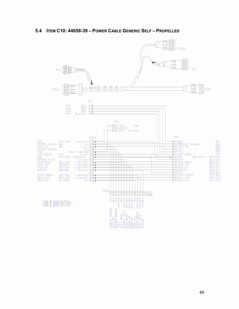
5.4 ITEM C10: 44658-39 – POWER CABLE GENERIC SELF – PROPELLED

41
5.5 ITEM C11: 44651-03 – EXTENSION CABLE VALVE GENERIC
42
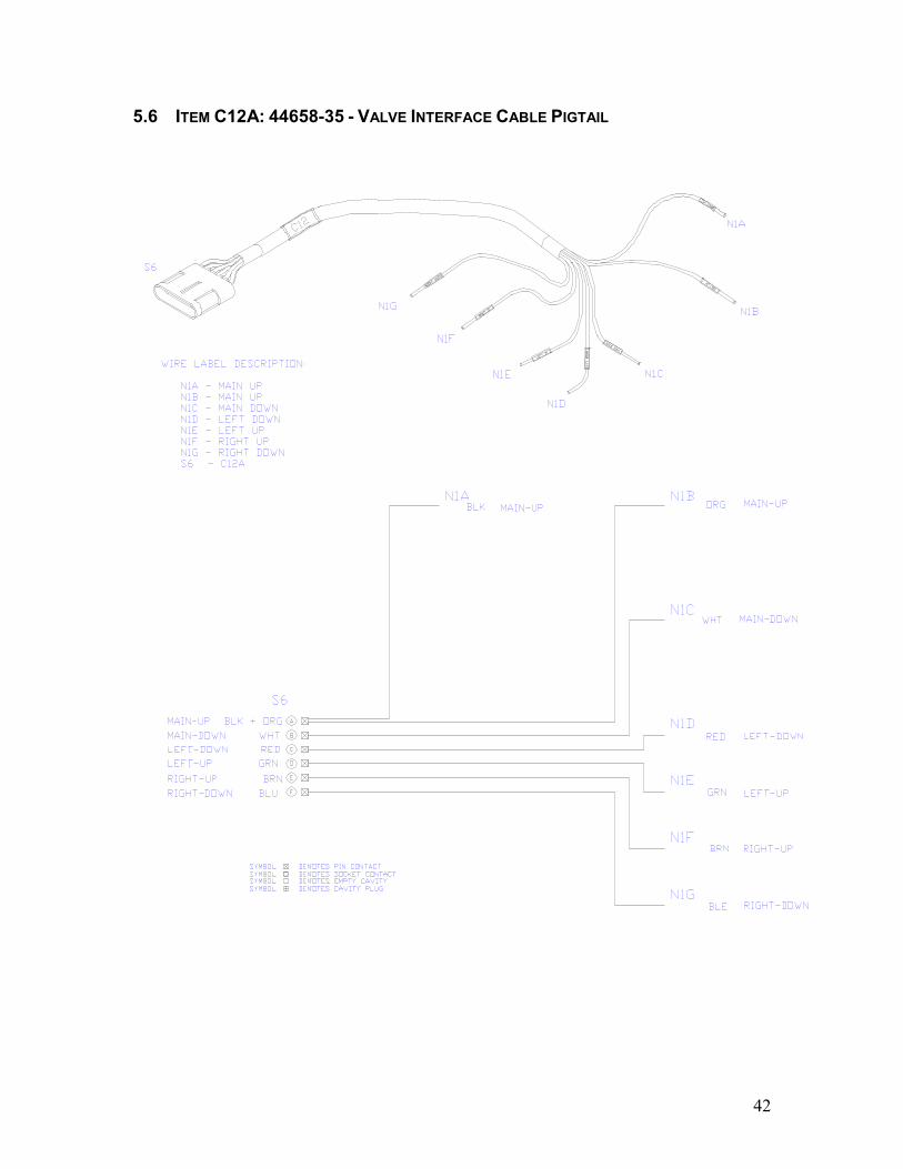
5.6 ITEM C12A: 44658-35 - VALVE INTERFACE CABLE PIGTAIL

43
5.7 ITEM C12B: 44658-36 – WING/BYPASS INTERFACE CABLE

44
5.8 ITEM C13: 44658-37: VALVE INTERFACE CABLE MAIN LIFT ONLY

45
5.9 ITEM C15: 44658-31 – HAND CONTROL INTERFACE CABLE

Canada
NORAC Systems International Inc.
CALL TOLL FREE: 1-800-667-3921
(306)664-6711
SHIPPING ADDRESS:
3702 Kinnear Place
Saskatoon, SK
S7P 0A6
United States
Norac, Inc.
CALL TOLL FREE: 1-866-306-6722
(763)786-3080
SHIPPING ADDRESS:
1290 Osborne Rd NE, Suite F Fridley, MN
55432-2892
www.norac.ca
Canada
NORAC Systems International Inc.
CALL TOLL FREE: 1-800-667-3921
(306)664-6711
SHIPPING ADDRESS:
3702 Kinnear Place
Saskatoon, SK
S7P 0A6
United States
NORAC, Inc.
CALL TOLL FREE: 1-866-306-6722
(763)786-3080
SHIPPING ADDRESS:
1290 Osborne Rd NE, Suite F Fridley, MN
55432-2892
Europe
NORAC Europe sarl
(+33) 06 03 87 80 78
SHIPPING ADDRESS:
Rue de l’hermitage
01090 Guereins
France
www.norac.ca


![MU AN2 [Recovered]](https://img.dokumen.tips/doc/110x75/55cf85cf550346484b919363/mu-an2-recovered.jpg)