Embed Size (px)
Citation preview
GeneralSpecifications
<<Contents>> <<Index>>
[Release 5]
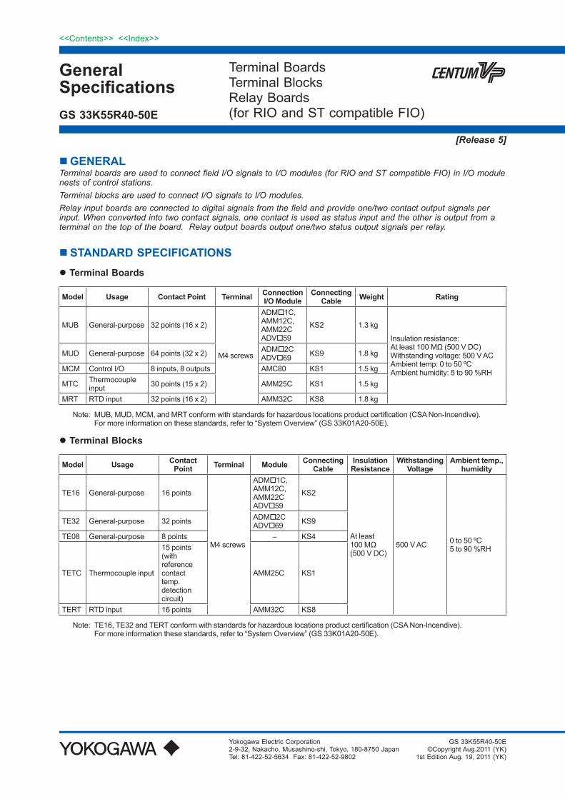
GENERALTerminal boards are used to connect field I/O signals to I/O modules (for RIO and ST compatible FIO) in I/O module nests of control stations.Terminal blocks are used to connect I/O signals to I/O modules.Relay input boards are connected to digital signals from the field and provide one/two contact output signals per input. When converted into two contact signals, one contact is used as status input and the other is output from a terminal on the top of the board. Relay output boards output one/two status output signals per relay.
STANDARD SPECIFICATIONS Terminal Boards
Model Usage Contact Point Terminal Connection I/O Module
Connecting Cable Weight Rating
MUB General-purpose 32 points (16 x 2)
M4 screws
ADM1C, AMM12C, AMM22C ADV59
KS2 1.3 kg
Insulation resistance: At least 100 MΩ (500 V DC) Withstanding voltage: 500 V AC Ambient temp: 0 to 50 ºCAmbient humidity: 5 to 90 %RH
MUD General-purpose 64 points (32 x 2) ADM2C ADV69 KS9 1.8 kg
MCM Control I/O 8 inputs, 8 outputs AMC80 KS1 1.5 kg
MTC Thermocouple input 30 points (15 x 2) AMM25C KS1 1.5 kg
MRT RTD input 32 points (16 x 2) AMM32C KS8 1.8 kg
Note: MUB, MUD, MCM, and MRT conform with standards for hazardous locations product certification (CSA Non-Incendive). For more information on these standards, refer to “System Overview” (GS 33K01A20-50E).
Terminal Blocks
Model Usage Contact Point Terminal Module Connecting
CableInsulation
ResistanceWithstanding
VoltageAmbient temp.,
humidity
TE16 General-purpose 16 points
M4 screws
ADM1C, AMM12C, AMM22C ADV59
KS2
At least 100 MΩ (500 V DC)
500 V AC 0 to 50 ºC 5 to 90 %RH
TE32 General-purpose 32 points ADM2C ADV69 KS9
TE08 General-purpose 8 points – KS4
TETC Thermocouple input
15 points (with reference contact temp. detection circuit)
AMM25C KS1
TERT RTD input 16 points AMM32C KS8
Note: TE16, TE32 and TERT conform with standards for hazardous locations product certification (CSA Non-Incendive). For more information these standards, refer to “System Overview” (GS 33K01A20-50E).
Terminal BoardsTerminal BlocksRelay Boards(for RIO and ST compatible FIO)
Yokogawa Electric Corporation2-9-32, Nakacho, Musashino-shi, Tokyo, 180-8750 JapanTel: 81-422-52-5634 Fax: 81-422-52-9802
GS 33K55R40-50E
GS 33K55R40-50E©Copyright Aug.2011 (YK)
1st Edition Aug. 19, 2011 (YK)
2
All Rights Reserved. Copyright © 2011, Yokogawa Electric Corporation
<<Contents>> <<Index>>
GS 33K55R40-50E Aug. 19, 2011-00
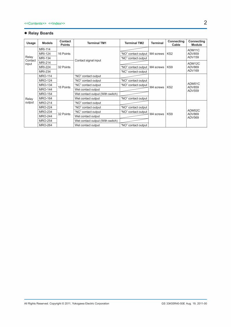
Relay Boards
Usage Models Contact Points Terminal TM1 Terminal TM2 Terminal Connecting
CableConnecting
Module
Relay Contact input
MRI-11416 Points
Contact signal input
M4 screws KS2ADM11CADV859ADV159
MRI-124 “NO” contact outputMRI-134 “NC” contact outputMRI-214
32 Points M4 screws KS9ADM12CADV869ADV169
MRI-224 “NO” contact outputMRI-234 “NC” contact output
Relay output
MRO-114
16 Points
“NO” contact output
M4 screws KS2ADM51CADV859ADV559
MRO-124 “NO” contact output “NO” contact outputMRO-134 “NC” contact output “NO” contact outputMRO-144 Wet contact outputMRO-154 Wet contact output (With switch)MRO-164 Wet contact output “NO” contact outputMRO-214
32 Points
“NO” contact output
M4 screws KS9ADM52CADV869ADV569
MRO-224 “NO” contact output “NO” contact outputMRO-234 “NC” contact output “NO” contact outputMRO-244 Wet contact outputMRO-254 Wet contact output (With switch)MRO-264 Wet contact output “NO” contact output
3<<Contents>> <<Index>>
All Rights Reserved. Copyright © 2011, Yokogawa Electric Corporation GS 33K55R40-50E
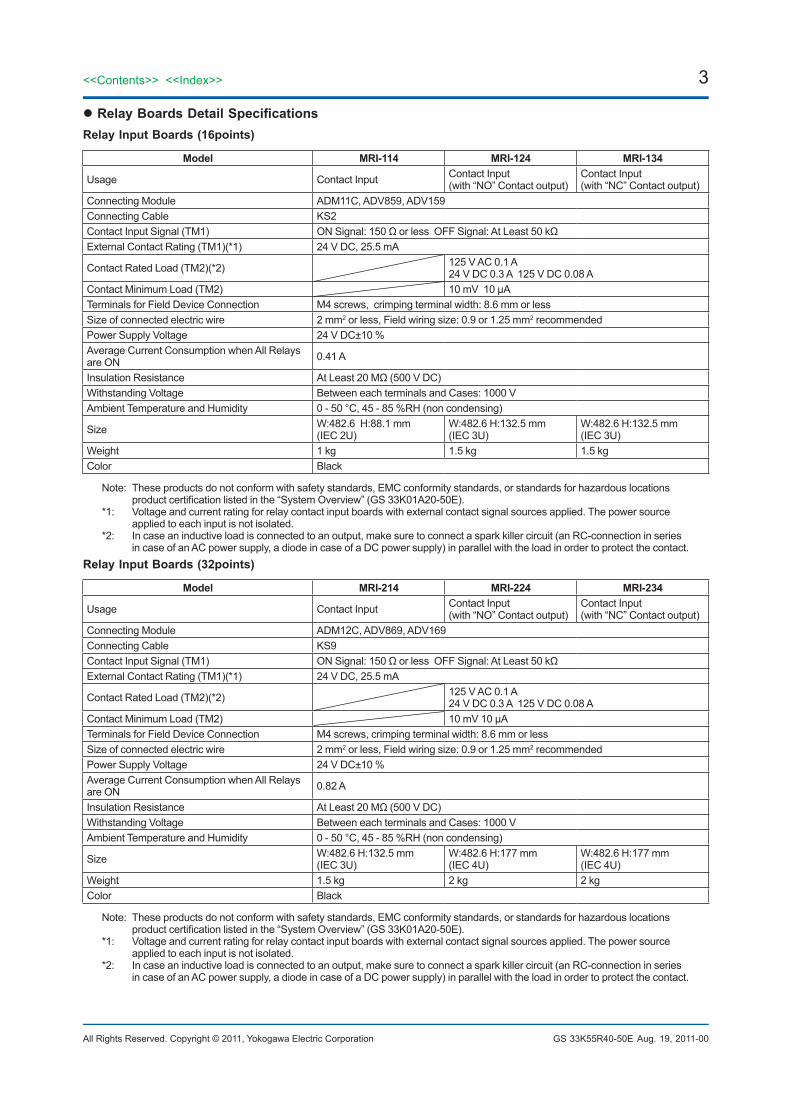
Relay Boards Detail SpecificationsRelay Input Boards (16points)
Model MRI-114 MRI-124 MRI-134
Usage Contact Input Contact Input(with “NO” Contact output)
Contact Input(with “NC” Contact output)
Connecting Module ADM11C, ADV859, ADV159Connecting Cable KS2Contact Input Signal (TM1) ON Signal: 150 Ω or less OFF Signal: At Least 50 kΩExternal Contact Rating (TM1)(*1) 24 V DC, 25.5 mA
Contact Rated Load (TM2)(*2) 125 V AC 0.1 A24 V DC 0.3 A 125 V DC 0.08 A
Contact Minimum Load (TM2) 10 mV 10 μATerminals for Field Device Connection M4 screws, crimping terminal width: 8.6 mm or lessSize of connected electric wire 2 mm2 or less, Field wiring size: 0.9 or 1.25 mm2 recommendedPower Supply Voltage 24 V DC±10 %Average Current Consumption when All Relays are ON 0.41 A
Insulation Resistance At Least 20 MΩ (500 V DC)Withstanding Voltage Between each terminals and Cases: 1000 VAmbient Temperature and Humidity 0 - 50 °C, 45 - 85 %RH (non condensing)
Size W:482.6 H:88.1 mm(IEC 2U)
W:482.6 H:132.5 mm(IEC 3U)
W:482.6 H:132.5 mm(IEC 3U)
Weight 1 kg 1.5 kg 1.5 kgColor Black
Note: These products do not conform with safety standards, EMC conformity standards, or standards for hazardous locations product certification listed in the “System Overview” (GS 33K01A20-50E).
*1: Voltage and current rating for relay contact input boards with external contact signal sources applied. The power source applied to each input is not isolated.
*2: In case an inductive load is connected to an output, make sure to connect a spark killer circuit (an RC-connection in series in case of an AC power supply, a diode in case of a DC power supply) in parallel with the load in order to protect the contact.
Relay Input Boards (32points)
Model MRI-214 MRI-224 MRI-234
Usage Contact Input Contact Input (with “NO” Contact output)
Contact Input (with “NC” Contact output)
Connecting Module ADM12C, ADV869, ADV169Connecting Cable KS9Contact Input Signal (TM1) ON Signal: 150 Ω or less OFF Signal: At Least 50 kΩExternal Contact Rating (TM1)(*1) 24 V DC, 25.5 mA
Contact Rated Load (TM2)(*2) 125 V AC 0.1 A24 V DC 0.3 A 125 V DC 0.08 A
Contact Minimum Load (TM2) 10 mV 10 μATerminals for Field Device Connection M4 screws, crimping terminal width: 8.6 mm or lessSize of connected electric wire 2 mm2 or less, Field wiring size: 0.9 or 1.25 mm2 recommendedPower Supply Voltage 24 V DC±10 %Average Current Consumption when All Relays are ON 0.82 A
Insulation Resistance At Least 20 MΩ (500 V DC)Withstanding Voltage Between each terminals and Cases: 1000 VAmbient Temperature and Humidity 0 - 50 °C, 45 - 85 %RH (non condensing)
Size W:482.6 H:132.5 mm (IEC 3U)
W:482.6 H:177 mm (IEC 4U)
W:482.6 H:177 mm (IEC 4U)
Weight 1.5 kg 2 kg 2 kgColor Black
Note: These products do not conform with safety standards, EMC conformity standards, or standards for hazardous locations product certification listed in the “System Overview” (GS 33K01A20-50E).
*1: Voltage and current rating for relay contact input boards with external contact signal sources applied. The power source applied to each input is not isolated.
*2: In case an inductive load is connected to an output, make sure to connect a spark killer circuit (an RC-connection in series in case of an AC power supply, a diode in case of a DC power supply) in parallel with the load in order to protect the contact.
Aug. 19, 2011-00
4<<Contents>> <<Index>>
All Rights Reserved. Copyright © 2011, Yokogawa Electric Corporation GS 33K55R40-50E
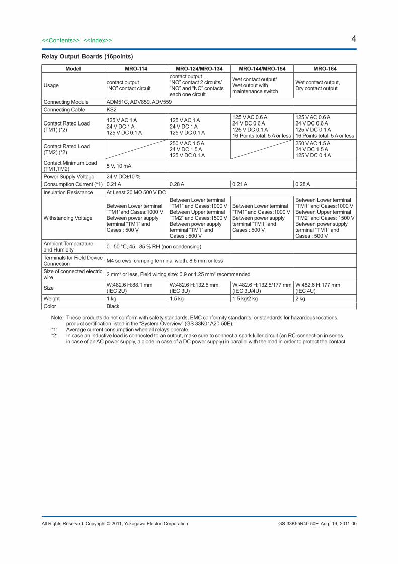
Relay Output Boards (16points)
Model MRO-114 MRO-124/MRO-134 MRO-144/MRO-154 MRO-164
Usage contact output “NO” contact circuit
contact output “NO” contact 2 circuits/”NO” and “NC” contacts each one circuit
Wet contact output/Wet output with maintenance switch
Wet contact output, Dry contact output
Connecting Module ADM51C, ADV859, ADV559Connecting Cable KS2
Contact Rated Load (TM1) (*2)
125 V AC 1 A 24 V DC 1 A 125 V DC 0.1 A
125 V AC 1 A 24 V DC 1 A 125 V DC 0.1 A
125 V AC 0.6 A 24 V DC 0.6 A 125 V DC 0.1 A16 Points total: 5 A or less
125 V AC 0.6 A24 V DC 0.6 A125 V DC 0.1 A16 Points total: 5 A or less
Contact Rated Load (TM2) (*2)
250 V AC 1.5 A 24 V DC 1.5 A 125 V DC 0.1 A
250 V AC 1.5 A 24 V DC 1.5 A 125 V DC 0.1 A
Contact Minimum Load (TM1,TM2) 5 V, 10 mA
Power Supply Voltage 24 V DC±10 %Consumption Current (*1) 0.21 A 0.28 A 0.21 A 0.28 AInsulation Resistance At Least 20 MΩ 500 V DC
Withstanding Voltage
Between Lower terminal “TM1”and Cases:1000 V Between power supply terminal “TM1” and Cases : 500 V
Between Lower terminal “TM1” and Cases:1000 V Between Upper terminal “TM2” and Cases:1500 VBetween power supply terminal “TM1” and Cases : 500 V
Between Lower terminal “TM1” and Cases:1000 V Between power supply terminal “TM1” and Cases : 500 V
Between Lower terminal “TM1” and Cases:1000 V Between Upper terminal “TM2” and Cases: 1500 V Between power supply terminal “TM1” and Cases : 500 V
Ambient Temperature and Humidity 0 - 50 °C, 45 - 85 % RH (non condensing)
Terminals for Field Device Connection M4 screws, crimping terminal width: 8.6 mm or less
Size of connected electric wire 2 mm2 or less, Field wiring size: 0.9 or 1.25 mm2 recommended
Size W:482.6 H:88.1 mm (IEC 2U)
W:482.6 H:132.5 mm (IEC 3U)
W:482.6 H:132.5/177 mm (IEC 3U/4U)
W:482.6 H:177 mm (IEC 4U)
Weight 1 kg 1.5 kg 1.5 kg/2 kg 2 kgColor Black
Note: These products do not conform with safety standards, EMC conformity standards, or standards for hazardous locations product certification listed in the “System Overview” (GS 33K01A20-50E).
*1: Average current consumption when all relays operate.*2: In case an inductive load is connected to an output, make sure to connect a spark killer circuit (an RC-connection in series
in case of an AC power supply, a diode in case of a DC power supply) in parallel with the load in order to protect the contact.
Aug. 19, 2011-00
5<<Contents>> <<Index>>
All Rights Reserved. Copyright © 2011, Yokogawa Electric Corporation GS 33K55R40-50E
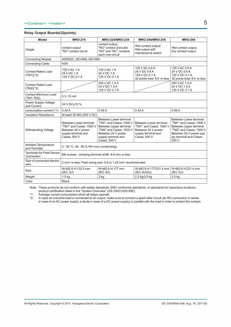
Relay Output Boards(32points)
Model MRO-214 MRO-224/MRO-234 MRO-244/MRO-254 MRO-264
Usage contact output “NO” contact circuit
contact output “NO” contact 2circuits/”NO” and “NC” contacts each one circuit
Wet contact output/Wet output with maintenance switch
Wet contact output, Dry contact output
Connecting Module ADM52C, ADV869, ADV569Connecting Cable KS9
Contact Rated Load (TM1)(*2)
125 V AC 1 A 24 V DC 1 A 125 V DC 0.1 A
125 V AC 1 A 24 V DC 1 A 125 V DC 0.1 A
125 V AC 0.6 A 24 V DC 0.6 A 125 V DC 0.1 A 32 points total: 8 A or less
125 V AC 0.6 A 24 V DC 0.6 A 125 V DC 0.1 A 32 points total: 8 A or less
Contact Rated Load (TM2)(*2)
250 V AC 1.5 A 24 V DC 1.5 A 125 V DC 0.1 A
250 V AC 1.5 A 24 V DC 1.5 A 125 V DC 0.1 A
Contact Minimum Load (TM1,TM2) 5 V, 10 mA
Power Supply Voltage and Current 24 V DC±10 %
consumption current (*1) 0.42 A 0.56 A 0.42 A 0.56 AInsulation Resistance At least 20 MΩ (500 V DC)
Withstanding Voltage
Between Lower terminal “TM1” and Cases: 1000 V Between 24 V power supply terminal and Cases: 500 V
Between Lower terminal “TM1” and Cases: 1000 V Between Upper terminal “TM2” and Cases: 1500 V Between 24 V power supply terminal and Cases: 500 V
Between Lower terminal “TM1” and Cases: 1000 V Between 24 V power supply terminal and Cases: 500 V
Between Lower terminal “TM1” and Cases: 1000 V Between Upper terminal “TM2” and Cases: 1500 V Between 24 V power supply terminal and Cases: 500 V
Ambient Temperature and Humidity 0 - 50 °C, 45 - 85 % RH (non condensing)
Terminals for Field Device Connection M4 screws, crimping terminal width: 8.6 mm or less
Size of connected electric wire 2 mm2 or less, Field wiring size: 0.9 or 1.25 mm2 recommended
Size W:482.6 H:132.5 mm (IEC 3U)
W:482.6 H:177 mm(IEC 4U)
W:482.6 H:177/221.4 mm(IEC 4U/5U)
W:482.6 H:221.4 mm (IEC 5U)
Weight 1.5 kg 2 kg 2.2 kg/2.5 kg 2.5 kgColor Black
Note: These products do not conform with safety standards, EMC conformity standards, or standards for hazardous locations product certification listed in the “System Overview” (GS 33K01A20-50E).
*1: Average current consumption when all relays operate.*2: In case an inductive load is connected to an output, make sure to connect a spark killer circuit (an RC-connection in series
in case of an AC power supply, a diode in case of a DC power supply) in parallel with the load in order to protect the contact.
Aug. 19, 2011-00
6<<Contents>> <<Index>>
All Rights Reserved. Copyright © 2011, Yokogawa Electric Corporation GS 33K55R40-50E
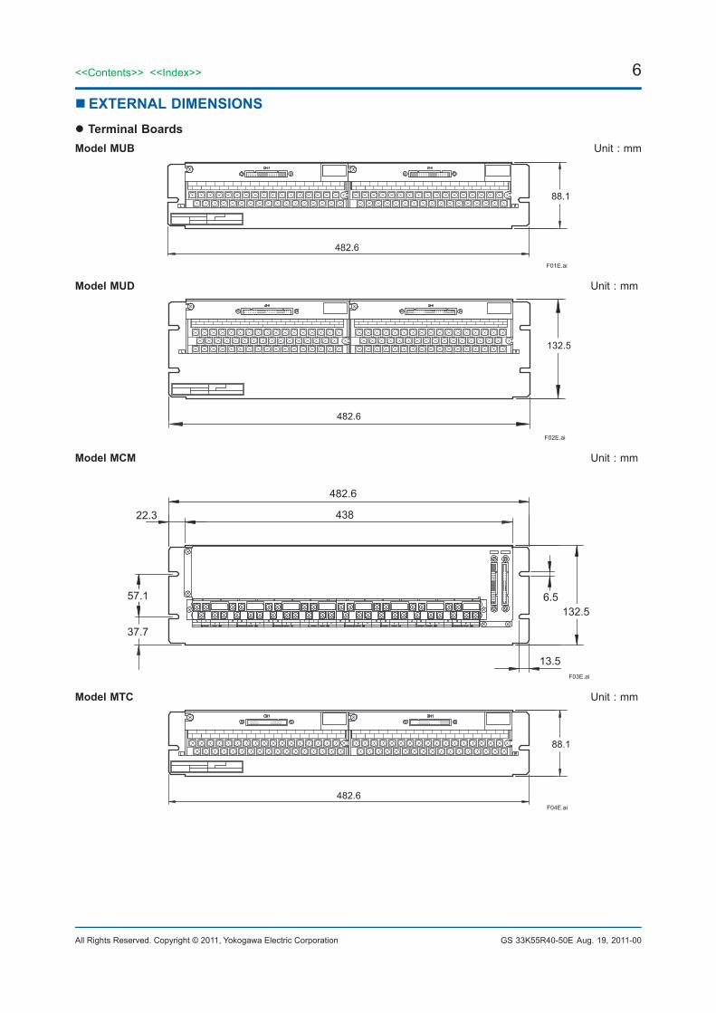
EXTERNAL DIMENSIONS Terminal BoardsModel MUB Unit : mm
482.6
F01E.ai
88.1
Model MUD Unit : mm
132.5
482.6
F02E.ai
Model MCM Unit : mm
6.557.1
37.7
132.5
13.5
482.6
43822.3
F03E.ai
Model MTC Unit : mm
482.6F04E.ai
88.1
Aug. 19, 2011-00
7
All Rights Reserved. Copyright © 2011, Yokogawa Electric Corporation
<<Contents>> <<Index>>
GS 33K55R40-50E
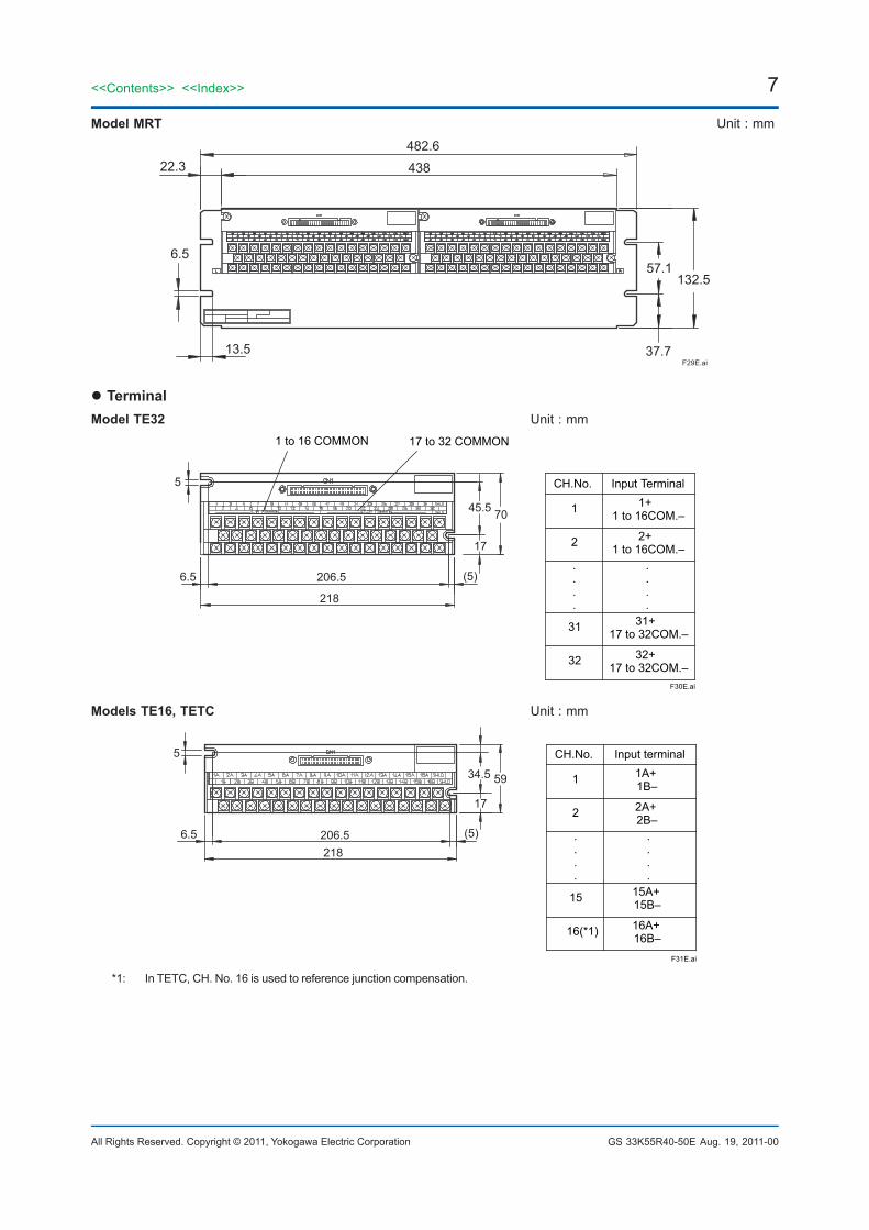
Model MRT Unit : mm
132.5
37.7
57.1
482.6
43822.3
6.5
13.5F29E.ai
TerminalModel TE32 Unit : mm
CH.No. Input Terminal
1 1+1 to 16COM.–
2 2+1 to 16COM.–
.
.
.
.
.
.
.
.
31 31+17 to 32COM.–
32 32+17 to 32COM.–
5
6.5 206.5
218
(5)
45.5 70
17
1 to 16 COMMON 17 to 32 COMMON
F30E.ai
Models TE16, TETC Unit : mm
(5)
17
34.5 59
5
6.5 206.5218
F31E.ai
CH.No. Input terminal
1 1A+1B–
2 2A+2B–
.
.
.
.
.
.
.
.
15 15A+15B–
16(*1) 16A+16B–
*1: In TETC, CH. No. 16 is used to reference junction compensation.
Aug. 19, 2011-00
8<<Contents>> <<Index>>
All Rights Reserved. Copyright © 2011, Yokogawa Electric Corporation GS 33K55R40-50E
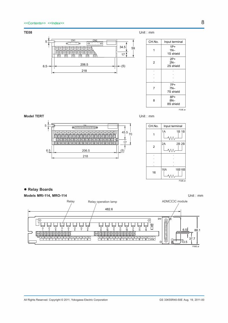
TE08 Unit : mm
S1
P S2
P S3
P S5
S4
N N N NNP P
CN1 CN2
206.5
218
5934.5
17
5
(5)6.5
CH.No. Input terminal
11P+1N–
1S shield
22P+2N–
2S shield....
.
.
.
.
77P+7N–
7S shield
88P+8N–
8S shield
F33E.ai
Model TERT Unit : mm
1A 2A 3A 4A 5A 6A 7A 8A 9A 10A 11A 12A 13A 14A 15A 16A
1B 2B 3B 4B 5B 6B 7B 8B 9B 10B 11B 12B 13B 14B 15B 16B1B 2B 3B 4B 5B 6B 7B 8B 9B 10B 11B 12B 13B 14B 15B 16B
CH.No. Input terminal
1
2
.
.
.
.
.
.
.
.
16
1A 1B 1B
2A 2B 2B
16A 16B16B
5
6.5 206.5
218
(5)
45.5 70
17
F32E.ai
Relay BoardsModels MRI-114, MRO-114 Unit : mm
482.6
F05E.ai
88.1
37.713.5
6.5
Relay Relay operation lamp ADMC module
Aug. 19, 2011-00

9
All Rights Reserved. Copyright © 2011, Yokogawa Electric Corporation
<<Contents>> <<Index>>
GS 33K55R40-50E
Models MRI-124, MRI-134Models MRO-124, MRO-134 Unit : mm
F06E.ai
482.6
132.5
37.713.5
6.5
57.1
Models MRI-214, MRO-214 Unit : mm
F07E.ai
482.6
132.5
37.713.5
6.5
57.1
Models MRI-224, MRI-234Models MRO-224, MRO-234 Unit : mm
F08E.ai
482.6
177
37.713.5
6.5
101.6
Aug. 19, 2011-00
10<<Contents>> <<Index>>
All Rights Reserved. Copyright © 2011, Yokogawa Electric Corporation GS 33K55R40-50E
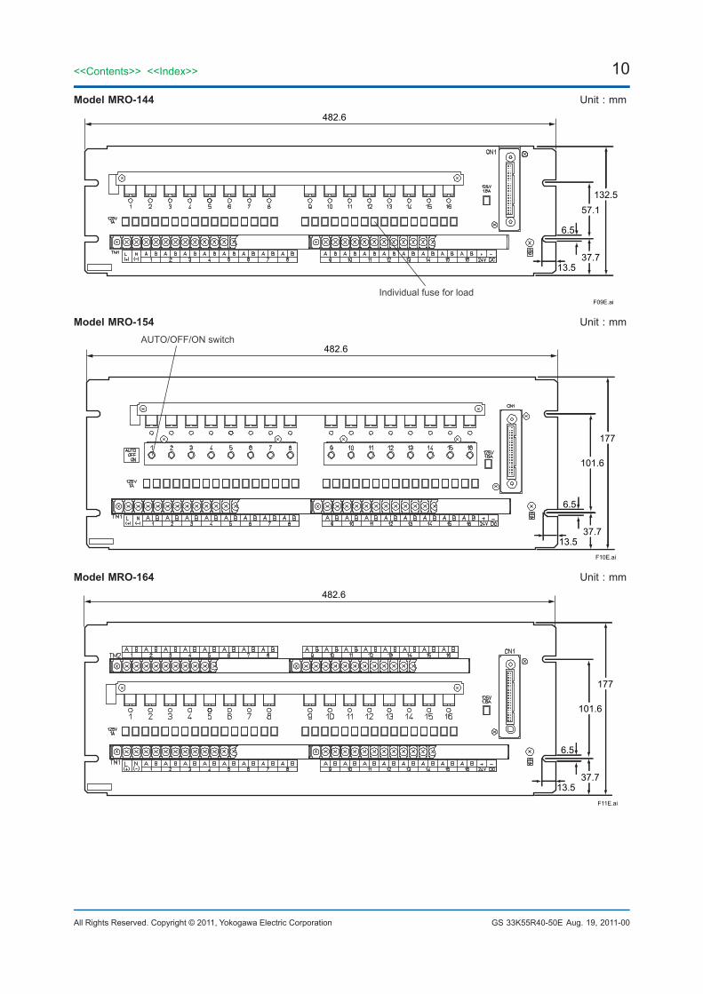
Model MRO-144 Unit : mm
F09E.ai
482.6
132.5
37.713.5
6.5
57.1
Individual fuse for load
Model MRO-154 Unit : mm
F10E.ai
482.6
177
37.713.5
6.5
101.6
AUTO/OFF/ON switch
Model MRO-164 Unit : mm
F11E.ai
482.6
177
37.713.5
6.5
101.6
Aug. 19, 2011-00
11
All Rights Reserved. Copyright © 2011, Yokogawa Electric Corporation
<<Contents>> <<Index>>
GS 33K55R40-50E
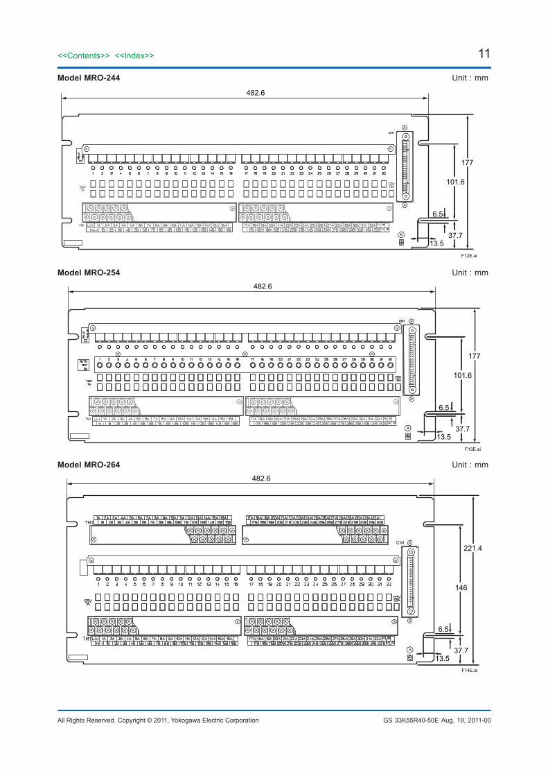
Model MRO-244 Unit : mm
F12E.ai
482.6
177
37.713.5
6.5
101.6
Model MRO-254 Unit : mm
F13E.ai
482.6
177
37.713.5
6.5
101.6
Model MRO-264 Unit : mm
F14E.ai
482.6
221.4
37.713.5
6.5
146
Aug. 19, 2011-00
12<<Contents>> <<Index>>
All Rights Reserved. Copyright © 2011, Yokogawa Electric Corporation GS 33K55R40-50E
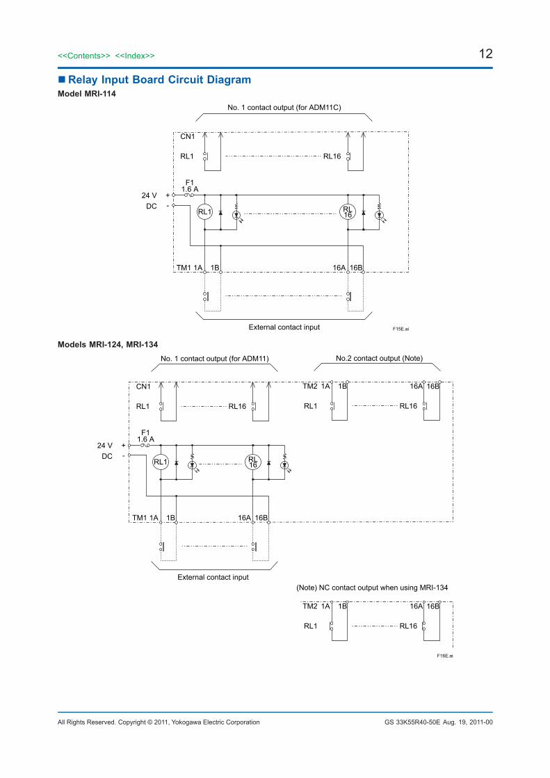
Relay Input Board Circuit DiagramModel MRI-114
CN1
RL1 RL16
No. 1 contact output (for ADM11C)
External contact input
24 VDC
+-
F11.6 A
RL1 RL16
TM1 1A 1B 16A 16B
F15E.ai
Models MRI-124, MRI-134
CN1
RL1 RL16
TM2
RL1
1A 1B
RL16
16A 16B
No. 1 contact output (for ADM11) No.2 contact output (Note)
External contact input
24 VDC
+-
F11.6 A
RL1 RL16
TM1 1A 1B 16A 16B
TM2
RL1
1A 1B
RL16
16A 16B
(Note) NC contact output when using MRI-134
F16E.ai
Aug. 19, 2011-00
13
All Rights Reserved. Copyright © 2011, Yokogawa Electric Corporation
<<Contents>> <<Index>>
GS 33K55R40-50E
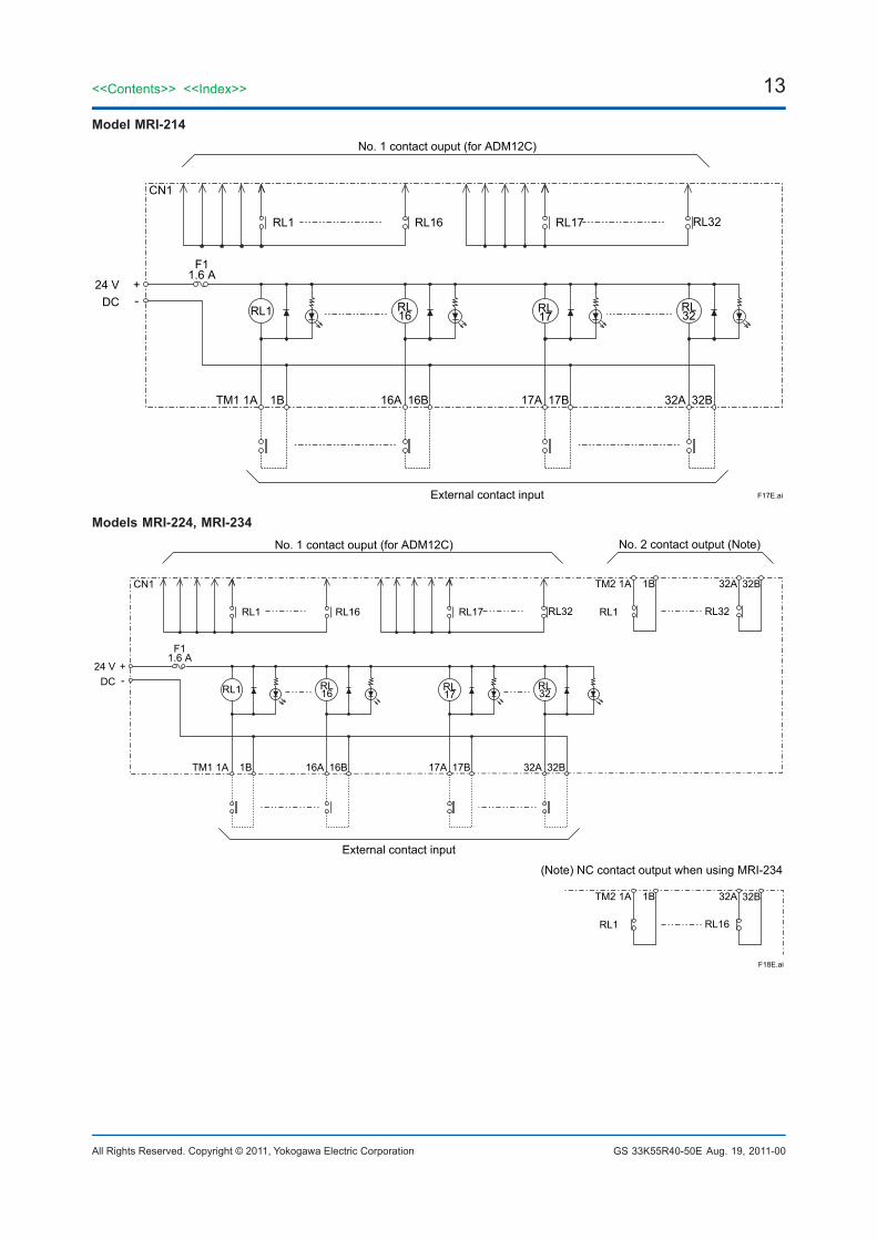
Model MRI-214
CN1
RL16RL1 RL32
No. 1 contact ouput (for ADM12C)
External contact input
24 VDC
+-
F11.6 A
RL1 RL16
TM1 1A 1B 16A 16B
RL17
RL17
RL32
17A 17B 32A 32B
F17E.ai
Models MRI-224, MRI-234
CN1
RL16RL1
TM2
RL32
1A 1B
RL32
32A 32B
No. 1 contact ouput (for ADM12C) No. 2 contact output (Note)
External contact input
+-
F11.6 A
RL1 RL16
TM1 1A 1B 16A 16B
(Note) NC contact output when using MRI-234
RL1RL17
TM2 1A 1B
RL16
32A 32B
RL1
RL17
RL32
17A 17B 32A 32B
F18E.ai
24 VDC
Aug. 19, 2011-00
14<<Contents>> <<Index>>
All Rights Reserved. Copyright © 2011, Yokogawa Electric Corporation GS 33K55R40-50E
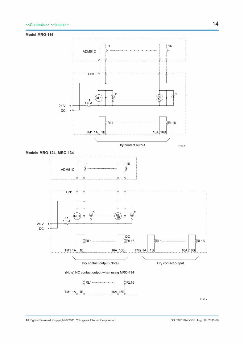
Model MRO-114
CN1
Dry contact output
+-
F11.6 A
TM1 1A 1B 16A 16B
RL1
1 16
RL16
RL1 RL16
ADM51C
F19E.ai
24 VDC
Models MRO-124, MRO-134
CN1
Dry contact output (Note)
24 VDC
+-
F11.6 A
TM1 1A 1B 16A 16B
(Note) NC contact output when using MRO-134
RL1
1 16
RL16
RL1 RL16
TM1 1A 1B 16A 16B
RL1 RL16
Dry contact output
TM2 1A 1B 16A 16B
RL1 RL16
ADM51C
F20E.ai
DC
Aug. 19, 2011-00
15
All Rights Reserved. Copyright © 2011, Yokogawa Electric Corporation
<<Contents>> <<Index>>
GS 33K55R40-50E
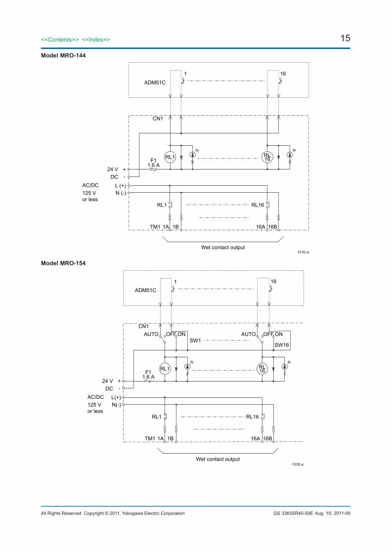
Model MRO-144
CN1
Wet contact output
+-
F11.6 A
1ATM1 1B 16A 16B
RL1
1 16
RL16
RL1
ADM51C
F21E.ai
RL16
24 VDC
AC/DC125 Vor less
L (+)N (-)
Model MRO-154
CN1AUTO OFF ON
SW1SW16
AUTO OFF ON
Wet contact output
F11.6 A
1ATM1 1B 16A 16B
RL1
1 16
RL16
RL1 RL16
ADM51C
F22E.ai
24 VDC
+-
AC/DC125 V or less
L(+)N(-)
Aug. 19, 2011-00
16<<Contents>> <<Index>>
All Rights Reserved. Copyright © 2011, Yokogawa Electric Corporation GS 33K55R40-50E
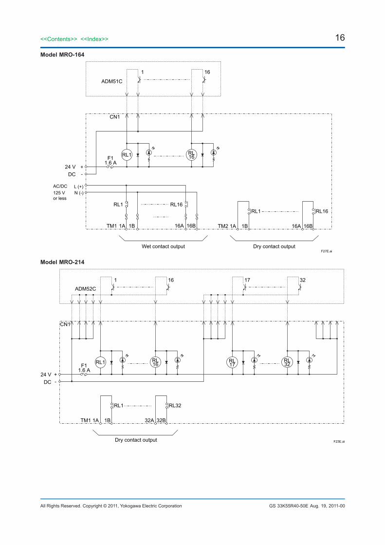
Model MRO-164
CN1
Wet contact output
F11.6 A
RL1
1 16
RL16
Dry contact output
TM2 1A 1B 16A 16B
RL1 RL16
ADM51C
F27E.ai
1ATM1 1B 16A 16B
RL1 RL16
+-
24 VDC
AC/DC125 Vor less
L (+)N (-)
Model MRO-214
CN1
24 VDC
+-
F11.6 A
RL1
1 16
RL16
ADM52C
F23E.aiDry contact output
TM1 1A 1B 32A 32B
RL1 RL32
RL17
17 32
RL32
Aug. 19, 2011-00
17
All Rights Reserved. Copyright © 2011, Yokogawa Electric Corporation
<<Contents>> <<Index>>
GS 33K55R40-50E
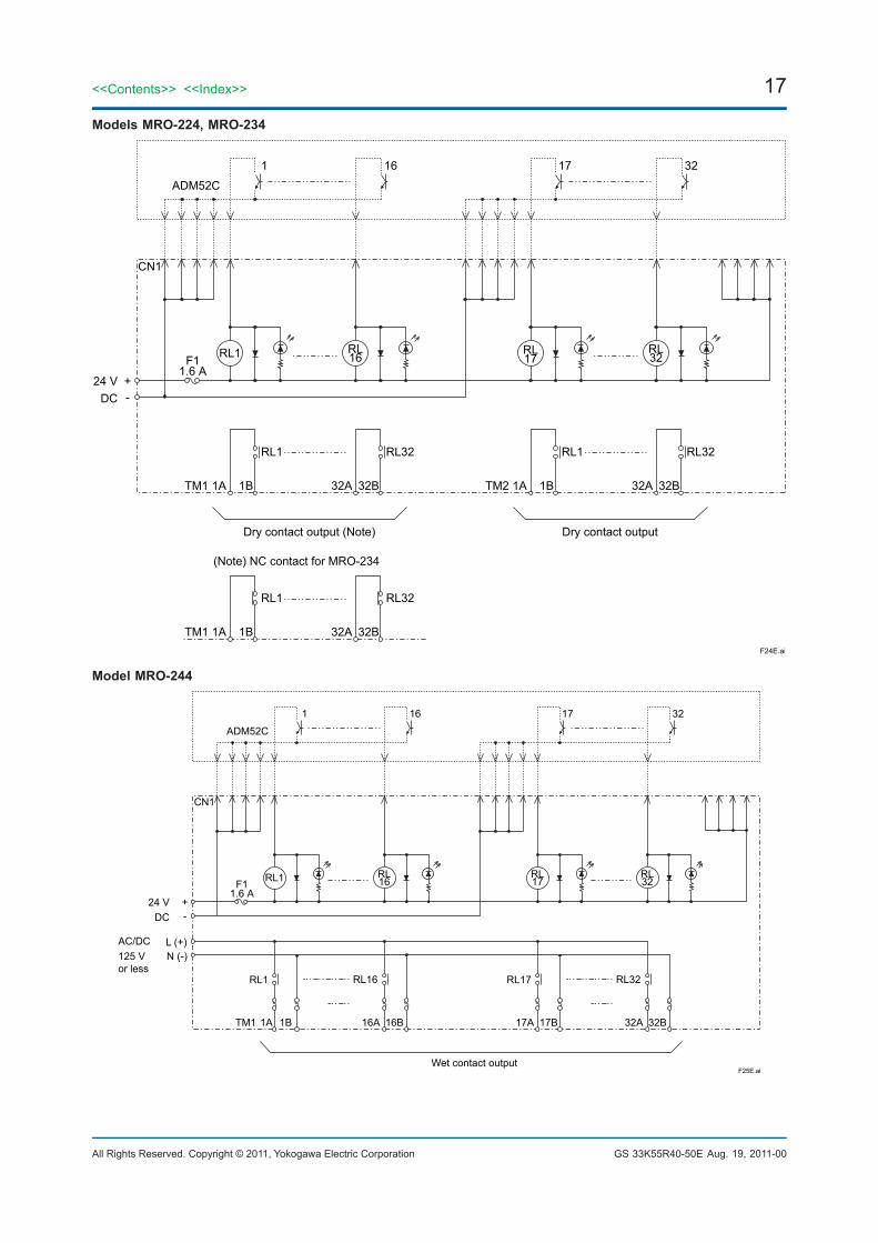
Models MRO-224, MRO-234
CN1
24 VDC
+-
F11.6 A
RL1
1 16
RL16
ADM52C
F24E.ai
Dry contact output (Note)
TM1 1A 1B 32A 32B
RL1 RL32
Dry contact output
TM2 1A 1B 32A 32B
RL1 RL32
RL17
17 32
RL32
TM1 1A 1B 32A 32B
RL1 RL32
(Note) NC contact for MRO-234
Model MRO-244
CN1
24 VDC
+-
F11.6 A
RL1
1 16
RL16
ADM52C
F25E.ai
RL17
17 32
RL32
Wet contact output
AC/DC125 Vor less
L (+)N (-)
1ATM1 1B 16A 16B
RL1 RL16
17A 17B 32A 32B
RL17 RL32
Aug. 19, 2011-00
18<<Contents>> <<Index>>
All Rights Reserved. Copyright © 2011, Yokogawa Electric Corporation GS 33K55R40-50E
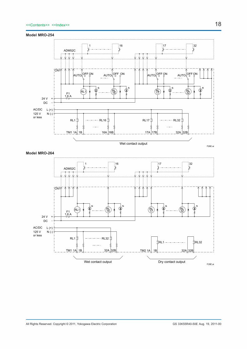
Model MRO-254
CN1
F11.6 A
RL1
1 16
RL16
ADM52C
F26E.ai
17 32
Wet contact output
1ATM1 1B 16A 16B
RL1 RL16
17A 17B 32A 32B
RL17 RL32
OFF ON AUTOAUTO AUTO AUTOOFF ON
RL17
RL32
OFF ON OFF ON
24 VDC
+-
L (+)N (-)
AC/DC125 Vor less
Model MRO-264
CN1
F11.6 A
RL1
1 16
RL16
ADM52C
F28E.ai
RL17
17 32
RL32
Wet contact output Dry contact output
TM2 1A 1B 32A 32B
RL1 RL32
1ATM1 1B 32A 32B
RL1 RL32
24 VDC
+-
AC/DC125 Vor less
L (+)N (-)
Aug. 19, 2011-00
19
All Rights Reserved. Copyright © 2011, Yokogawa Electric Corporation
<<Contents>> <<Index>>
GS 33K55R40-50E
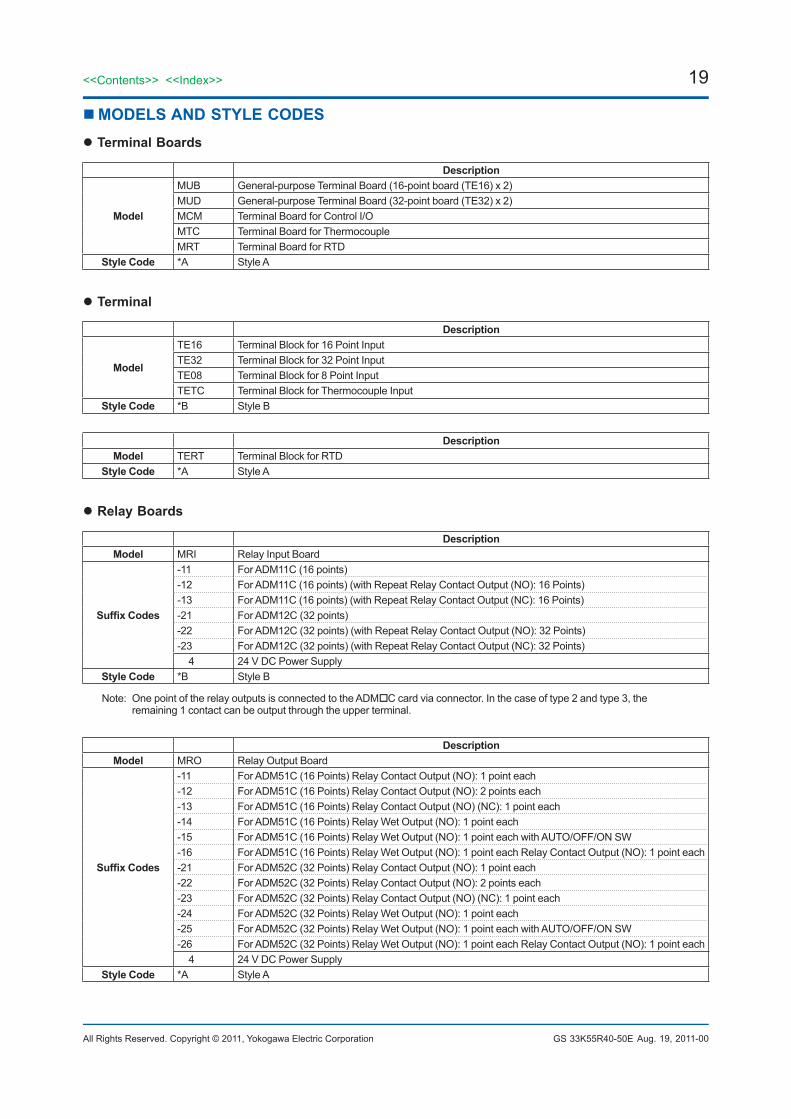
MODELS AND STYLE CODES Terminal Boards
Description
Model
MUB General-purpose Terminal Board (16-point board (TE16) x 2) MUD General-purpose Terminal Board (32-point board (TE32) x 2) MCM Terminal Board for Control I/OMTC Terminal Board for Thermocouple MRT Terminal Board for RTD
Style Code *A Style A
Terminal
Description
Model
TE16 Terminal Block for 16 Point InputTE32 Terminal Block for 32 Point InputTE08 Terminal Block for 8 Point Input TETC Terminal Block for Thermocouple Input
Style Code *B Style B
Description Model TERT Terminal Block for RTD
Style Code *A Style A
Relay Boards
Description Model MRI Relay Input Board
Suffix Codes
-11 For ADM11C (16 points) -12 For ADM11C (16 points) (with Repeat Relay Contact Output (NO): 16 Points) -13 For ADM11C (16 points) (with Repeat Relay Contact Output (NC): 16 Points) -21 For ADM12C (32 points) -22 For ADM12C (32 points) (with Repeat Relay Contact Output (NO): 32 Points) -23 For ADM12C (32 points) (with Repeat Relay Contact Output (NC): 32 Points) 4 24 V DC Power Supply
Style Code *B Style B
Note: One point of the relay outputs is connected to the ADMC card via connector. In the case of type 2 and type 3, the remaining 1 contact can be output through the upper terminal.
Description Model MRO Relay Output Board
Suffix Codes
-11 For ADM51C (16 Points) Relay Contact Output (NO): 1 point each -12 For ADM51C (16 Points) Relay Contact Output (NO): 2 points each -13 For ADM51C (16 Points) Relay Contact Output (NO) (NC): 1 point each -14 For ADM51C (16 Points) Relay Wet Output (NO): 1 point each -15 For ADM51C (16 Points) Relay Wet Output (NO): 1 point each with AUTO/OFF/ON SW -16 For ADM51C (16 Points) Relay Wet Output (NO): 1 point each Relay Contact Output (NO): 1 point each -21 For ADM52C (32 Points) Relay Contact Output (NO): 1 point each -22 For ADM52C (32 Points) Relay Contact Output (NO): 2 points each -23 For ADM52C (32 Points) Relay Contact Output (NO) (NC): 1 point each -24 For ADM52C (32 Points) Relay Wet Output (NO): 1 point each -25 For ADM52C (32 Points) Relay Wet Output (NO): 1 point each with AUTO/OFF/ON SW -26 For ADM52C (32 Points) Relay Wet Output (NO): 1 point each Relay Contact Output (NO): 1 point each 4 24 V DC Power Supply
Style Code *A Style A
Aug. 19, 2011-00
20
All Rights Reserved. Copyright © 2011, Yokogawa Electric Corporation
<<Contents>> <<Index>>
GS 33K55R40-50E
ORDERING INFORMATIONSpecify model, suffix codes, and style code.
TRADEMARK• CENTUM is a registered trademark of Yokogawa Electric Corporation.• Other company and product names appearing in this document are trademarks or registered trademarks of their
respective holders.
Aug. 19, 2011-00Subject to change without notice.