Embed Size (px)
Citation preview
GeneralSpecifications
<<Contents>> <<Index>>
[Release 3]
ProSafe-RS Outline of I/O Modules
Yokogawa Electric Corporation2-9-32, Nakacho, Musashino-shi, Tokyo, 180-8750 Japan
GS 32Q06K20-31E
GS 32Q06K20-31E©Copyright July 2011 (YK)
4th Edition Nov. 28, 2012 (YK)
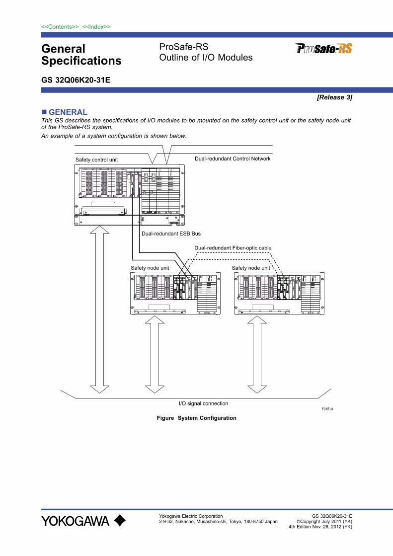
GENERALThis GS describes the specifications of I/O modules to be mounted on the safety control unit or the safety node unit of the ProSafe-RS system.An example of a system configuration is shown below.
F01E.ai
Safety node unit Safety node unit
I/O signal connection
Dual-redundant ESB Bus
Dual-redundant Control Network
Dual-redundant Fiber-optic cable
Safety control unit
Figure System Configuration

2
All Rights Reserved. Copyright © 2011, Yokogawa Electric Corporation
<<Contents>> <<Index>>
GS 32Q06K20-31E
COMMON SPECIFICATIONS Installation Environment
Item Specifications
TemperatureNormal operation –20 to 70 °C (*1) (*2)Transportation/storage –40 to 85 °C
HumidityNormal operation 5 to 95 % RH (non-condensing) 5 to 85 % RH when the
SRM53D/SRM54D/SBM54D is mounted.Transportation/storage 5 to 95 % RH (non-condensing)
Temperature change
During operation Within ±10 °C/h
Transportation/storage Within ±20 °C/h
Power supply
Voltage range100 to 120 V AC –15 %, +10 % 220 to 240 V AC –15 %, +10 % 24 V DC: –10 % to +20 %
Frequency 50/60 Hz ± 3 Hz
Distortion factor 10 % or less
Crest factor 100 V system: 118 V or larger220 V system : 258 V or larger
Momentary failure 20 ms or less (when receiving the rated AC voltage)
DC power supply ripple rate 1 % p-p maximum
Withstanding voltage 1500 V AC for 1 minute (for 100 to 120/220 to 240 V AC)
Between power & ground terminals
Insulation resistance 20 M ohms at 500 V DC Between power & ground terminals
Grounding 100 ohms or less, independent grounding
Dust Maximum of 0.3 mg/m3
Corrosive gas ANSI/ISA S71.04 G3 (standard) Excluding SRM53D/SRM54D/SBM54D
NoiseElectric field 10 V/m maximum (80 MHz to 1 GHz)
Static electricity 4 kV or less (direct discharge) 8 kV or less (aerial discharge)
Vibration
Continuous vibration Amplitude: 1.75 mm (5 Hz to 9 Hz)Acceleration: 4.9 m/s2 (9 Hz to 150 Hz)
Non-continuous vibration Amplitude: 3.5 mm (5 Hz to 9 Hz)Acceleration: 9.8 m/s2 (9 Hz to 150 Hz)
Seismic Acceleration: 4.9 m/s2 or less
Transportation Horizontal: 4.9 m/s2 or less vertical: 9.8 m/s2 or less when packaged
Impact 147 m/s2 or less, 11 ms
Altitude 2000 m above sea level or less
*1: 60 to 70 °C: Refer to “NODE UNIT MOUNTING RESTRICTIONS” section. *2: When ALR111-S01/ALR121-S01 is installed, the ambient temperature should range from 0 to 60 °C. In case of
ALR121-S0B, it should range from 0 to 70 °C. When ALE111-S01 is installed, the ambient temperature should range from 0 to 60 °C.
Nov. 28, 2012-00
3<<Contents>> <<Index>>
All Rights Reserved. Copyright © 2011, Yokogawa Electric Corporation GS 32Q06K20-31E
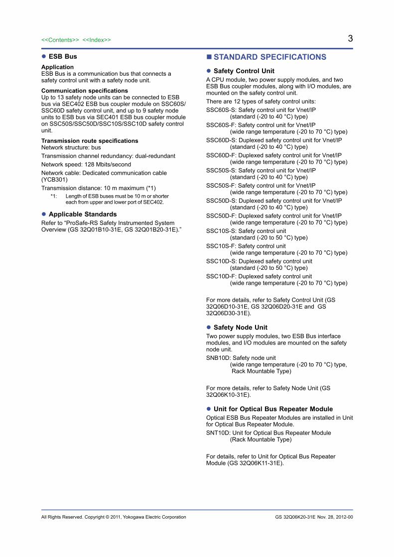
ESB BusApplicationESB Bus is a communication bus that connects a safety control unit with a safety node unit.
Communication specificationsUp to 13 safety node units can be connected to ESB bus via SEC402 ESB bus coupler module on SSC60S/SSC60D safety control unit, and up to 9 safety node units to ESB bus via SEC401 ESB bus coupler module on SSC50S/SSC50D/SSC10S/SSC10D safety control unit.
Transmission route specificationsNetwork structure: busTransmission channel redundancy: dual-redundantNetwork speed: 128 Mbits/secondNetwork cable: Dedicated communication cable (YCB301)Transmission distance: 10 m maximum (*1)
*1: Length of ESB buses must be 10 m or shorter each from upper and lower port of SEC402.
Applicable StandardsRefer to “ProSafe-RS Safety Instrumented System Overview (GS 32Q01B10-31E, GS 32Q01B20-31E).”
STANDARD SPECIFICATIONS Safety Control UnitA CPU module, two power supply modules, and two ESB Bus coupler modules, along with I/O modules, are mounted on the safety control unit.There are 12 types of safety control units:SSC60S-S: Safety control unit for Vnet/IP (standard (-20 to 40 °C) type)SSC60S-F: Safety control unit for Vnet/IP (wide range temperature (-20 to 70 °C) type)SSC60D-S: Duplexed safety control unit for Vnet/IP (standard (-20 to 40 °C) type)SSC60D-F: Duplexed safety control unit for Vnet/IP (wide range temperature (-20 to 70 °C) type)SSC50S-S: Safety control unit for Vnet/IP (standard (-20 to 40 °C) type)SSC50S-F: Safety control unit for Vnet/IP (wide range temperature (-20 to 70 °C) type)SSC50D-S: Duplexed safety control unit for Vnet/IP (standard (-20 to 40 °C) type)SSC50D-F: Duplexed safety control unit for Vnet/IP (wide range temperature (-20 to 70 °C) type)SSC10S-S: Safety control unit (standard (-20 to 50 °C) type)SSC10S-F: Safety control unit (wide range temperature (-20 to 70 °C) type)SSC10D-S: Duplexed safety control unit (standard (-20 to 50 °C) type)SSC10D-F: Duplexed safety control unit (wide range temperature (-20 to 70 °C) type)
For more details, refer to Safety Control Unit (GS 32Q06D10-31E, GS 32Q06D20-31E and GS 32Q06D30-31E).
Safety Node UnitTwo power supply modules, two ESB Bus interface modules, and I/O modules are mounted on the safety node unit.SNB10D: Safety node unit (wide range temperature (-20 to 70 °C) type, Rack Mountable Type)
For more details, refer to Safety Node Unit (GS 32Q06K10-31E).
Unit for Optical Bus Repeater ModuleOptical ESB Bus Repeater Modules are installed in Unit for Optical Bus Repeater Module.SNT10D: Unit for Optical Bus Repeater Module (Rack Mountable Type)
For details, refer to Unit for Optical Bus Repeater Module (GS 32Q06K11-31E).
Nov. 28, 2012-00
4
All Rights Reserved. Copyright © 2011, Yokogawa Electric Corporation
<<Contents>> <<Index>>
GS 32Q06K20-31E
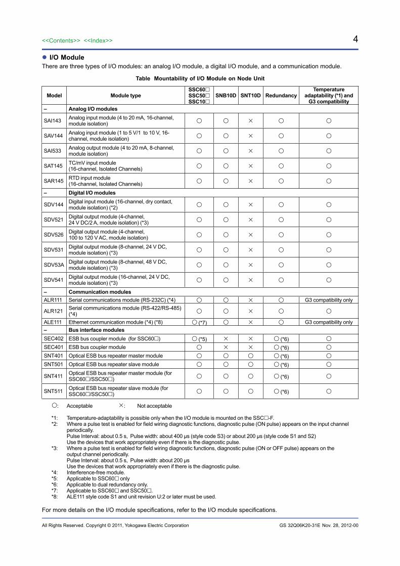
I/O ModuleThere are three types of I/O modules: an analog I/O module, a digital I/O module, and a communication module.
Table Mountability of I/O Module on Node Unit
Model Module typeSSC60SSC50SSC10
SNB10D SNT10D RedundancyTemperature
adaptability (*1) and G3 compatibility
– Analog I/O modules
SAI143 Analog input module (4 to 20 mA, 16-channel, module isolation)
SAV144 Analog input module (1 to 5 V/1 to 10 V, 16-channel, module isolation)
SAI533 Analog output module (4 to 20 mA, 8-channel, module isolation)
SAT145 TC/mV input module(16-channel, Isolated Channels)
SAR145 RTD input module(16-channel, Isolated Channels)
– Digital I/O modules
SDV144 Digital input module (16-channel, dry contact, module isolation) (*2)
SDV521 Digital output module (4-channel, 24 V DC/2 A, module isolation) (*3)
SDV526 Digital output module (4-channel, 100 to 120 V AC, module isolation)
SDV531 Digital output module (8-channel, 24 V DC, module isolation) (*3)
SDV53A Digital output module (8-channel, 48 V DC, module isolation) (*3)
SDV541 Digital output module (16-channel, 24 V DC, module isolation) (*3)
– Communication modulesALR111 Serial communications module (RS-232C) (*4) G3 compatibility only
ALR121 Serial communications module (RS-422/RS-485) (*4)
ALE111 Ethernet communication module (*4) (*8) (*7) G3 compatibility only– Bus interface modulesSEC402 ESB bus coupler module (for SSC60) (*5) (*6) SEC401 ESB bus coupler module (*6) SNT401 Optical ESB bus repeater master module (*6) SNT501 Optical ESB bus repeater slave module (*6)
SNT411 Optical ESB bus repeater master module (for SSC60/SSC50) (*6)
SNT511 Optical ESB bus repeater slave module (for SSC60/SSC50) (*6)
: Acceptable : Not acceptable
*1: Temperature-adaptability is possible only when the I/O module is mounted on the SSC-F.*2: Where a pulse test is enabled for field wiring diagnostic functions, diagnostic pulse (ON pulse) appears on the input channel
periodically. Pulse Interval: about 0.5 s, Pulse width: about 400 µs (style code S3) or about 200 µs (style code S1 and S2)
Use the devices that work appropriately even if there is the diagnostic pulse.*3: Where a pulse test is enabled for field wiring diagnostic functions, diagnostic pulse (ON or OFF pulse) appears on the
output channel periodically. Pulse Interval: about 0.5 s, Pulse width: about 200 µs
Use the devices that work appropriately even if there is the diagnostic pulse.*4: Interference-free module. *5: Applicable to SSC60 only*6: Applicable to dual redundancy only.*7: Applicable to SSC60 and SSC50.*8: ALE111 style code S1 and unit revision U:2 or later must be used.
For more details on the I/O module specifications, refer to the I/O module specifications.
Nov. 28, 2012-00
5<<Contents>> <<Index>>
All Rights Reserved. Copyright © 2011, Yokogawa Electric Corporation GS 32Q06K20-31E
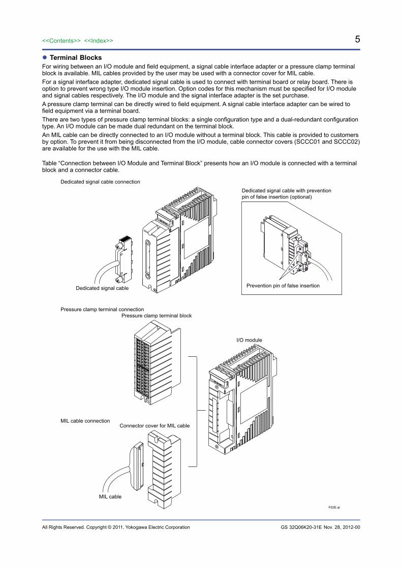
Terminal BlocksFor wiring between an I/O module and field equipment, a signal cable interface adapter or a pressure clamp terminal block is available. MIL cables provided by the user may be used with a connector cover for MIL cable.For a signal interface adapter, dedicated signal cable is used to connect with terminal board or relay board. There is option to prevent wrong type I/O module insertion. Option codes for this mechanism must be specified for I/O module and signal cables respectively. The I/O module and the signal interface adapter is the set purchase.A pressure clamp terminal can be directly wired to field equipment. A signal cable interface adapter can be wired to field equipment via a terminal board.There are two types of pressure clamp terminal blocks: a single configuration type and a dual-redundant configuration type. An I/O module can be made dual redundant on the terminal block.An MIL cable can be directly connected to an I/O module without a terminal block. This cable is provided to customers by option. To prevent it from being disconnected from the I/O module, cable connector covers (SCCC01 and SCCC02) are available for the use with the MIL cable.
Table “Connection between I/O Module and Terminal Block” presents how an I/O module is connected with a terminal block and a connector cable.
F02E.ai
Dedicated signal cable connection
Pressure clamp terminal connection
MIL cable connection
MIL cable
I/O module
Connector cover for MIL cable
Pressure clamp terminal block
Dedicated signal cable
Dedicated signal cable with preventionpin of false insertion (optional)
Prevention pin of false insertion
Nov. 28, 2012-00

6
All Rights Reserved. Copyright © 2011, Yokogawa Electric Corporation
<<Contents>> <<Index>>
GS 32Q06K20-31E
Table I/O Module and Signal Connection
Model Module typeNumber of I/O
points channels per module
Signal connection
Pressure clamp terminal Dedicated cable (*1) MIL cable
– Analog I/O modules
SAI143 Analog input module (4 to 20 mA, module isolation) (*2) 16
SAV144 Analog input module (1 to 5 V/ 1 to 10 V, module isolation) (*2) 16
SAI533 Analog output module (4 to 20 mA, module isolation) (*2) 8
SAT145 TC/mV input module(isolated channels) 16
SAR145 RTD input module(isolated channels) 16
– Digital I/O modules
SDV144 Digital input module (contact input, module isolation) (*2) 16
SDV521 Digital output module (24 V DC/2 A, module isolation) (*2) 4
SDV526 Digital output module (100 to 120 V AC, module isolation) (*2) 4
SDV531 Digital output module (24 V DC, module isolation) (*2) 8
SDV53A Digital output module (48 V DC, module isolation) (*2) 8
SDV541 Digital output module (24 V DC, module isolation) (*2) 16
– Communication modules
ALR111 Serial communication module 2 ports (D-sub 9-pin) (*3)
ALR121 Serial communication module 2 ports
(M4 terminal block 10-pole) (*3)
ALE111 Ethernet communication module 1 port (RJ-45) (*3)
: Connectable: Not connectable*1: This cable for connecting I/O modules with terminal boards, and relay boards, is a Yokogawa Electric Corporation dedicated
cable.*2: Depending on the I/O module’s connection configuration, there are restrictions regarding current, cable length, and the like. *3: The dedicated signal cable can be connected directly to the I/O module without the terminal block.
Nov. 28, 2012-00
7<<Contents>> <<Index>>
All Rights Reserved. Copyright © 2011, Yokogawa Electric Corporation GS 32Q06K20-31E
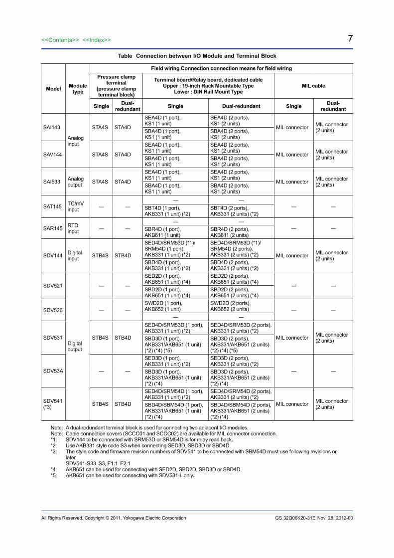
Table Connection between I/O Module and Terminal Block
Model Moduletype
Field wiring Connection connection means for field wiringPressure clamp
terminal(pressure clampterminal block)
Terminal board/Relay board, dedicated cableUpper : 19-inch Rack Mountable Type
Lower : DIN Rail Mount TypeMIL cable
Single Dual- redundant Single Dual-redundant Single Dual-
redundant
SAI143
Analoginput
STA4S STA4D
SEA4D (1 port),KS1 (1 unit)
SEA4D (2 ports),KS1 (2 units)
MIL connector MIL connector(2 units)SBA4D (1 port),
KS1 (1 unit)SBA4D (2 ports),KS1 (2 units)
SAV144 STA4S STA4D
SEA4D (1 port),KS1 (1 unit)
SEA4D (2 ports),KS1 (2 units)
MIL connector MIL connector(2 units)SBA4D (1 port),
KS1 (1 unit)SBA4D (2 ports),KS1 (2 units)
SAI533 Analogoutput STA4S STA4D
SEA4D (1 port),KS1 (1 unit)
SEA4D (2 ports),KS1 (2 units)
MIL connector MIL connector(2 units)SBA4D (1 port),
KS1 (1 unit)SBA4D (2 ports),KS1 (2 units)
SAT145 TC/mVinput ― ―
― ― ― ― SBT4D (1 port),
AKB331 (1 unit) (*2)SBT4D (2 ports),AKB331 (2 units) (*2)
SAR145 RTDinput ― ―
― ― ― ― SBR4D (1 port),
AKB611 (1 unit)SBR4D (2 ports),AKB611 (2 units)
SDV144 Digitalinput STB4S STB4D
SED4D/SRM53D (*1)/SRM54D (1 port),AKB331 (1 unit) (*2)
SED4D/SRM53D (*1)/SRM54D (2 ports),AKB331 (2 units) (*2) MIL connector MIL connector
(2 units)SBD4D (1 port),AKB331 (1 unit) (*2)
SBD4D (2 ports),AKB331 (2 units) (*2)
SDV521
Digitaloutput
― ―
SED2D (1 port),AKB651 (1 unit) (*4)
SED2D (2 ports),AKB651 (2 units) (*4)
― ― SBD2D (1 port),AKB651 (1 unit) (*4)
SBD2D (2 ports),AKB651 (2 units) (*4)
SDV526 ― ―SWD2D (1 port),AKB652 (1 unit)
SWD2D (2 ports),AKB652 (2 units) ― ―
― ―
SDV531 STB4S STB4D
SED4D/SRM53D (1 port),AKB331 (1 unit) (*2)
SED4D/SRM53D (2 ports),AKB331 (2 units) (*2)
MIL connector MIL connector(2 units)SBD3D (1 port),
AKB331/AKB651 (1 unit) (*2) (*4) (*5)
SBD3D (2 ports),AKB331/AKB651 (2 units) (*2) (*4) (*5)
SDV53A ― ―
SED3D (1 port),AKB331 (1 unit) (*2)
SED3D (2 ports),AKB331 (2 units) (*2)
― ― SBD3D (1 port),AKB331/AKB651 (1 unit) (*2) (*4)
SBD3D (2 ports),AKB331/AKB651 (2 units) (*2) (*4)
SDV541 (*3) STB4S STB4D
SED4D/SRM54D (1 port),AKB331 (1 unit) (*2)
SED4D/SRM54D (2 ports),AKB331 (2 units) (*2)
MIL connector MIL connector(2 units)SBD4D/SBM54D (1 port),
AKB331/AKB651 (1 unit) (*2) (*4)
SBD4D/SBM54D (2 ports),AKB331/AKB651 (2 units) (*2) (*4)
Note: A dual-redundant terminal block is used for connecting two adjacent I/O modules.Note: Cable connection covers (SCCC01 and SCCC02) are available for MIL connector connection.*1: SDV144 to be connected with SRM53D or SRM54D is for relay read back.*2: Use AKB331 style code S3 when connecting SED3D, SBD3D or SBD4D.*3: The style code and firmware revision numbers of SDV541 to be connected with SBM54D must use following revisions or
later. SDV541-S33 S3, F1:1 F2:1*4: AKB651 can be used for connecting with SED2D, SBD2D, SBD3D or SBD4D.*5: AKB651 can be used for connecting with SDV531-L only.
Nov. 28, 2012-00
8
All Rights Reserved. Copyright © 2011, Yokogawa Electric Corporation
<<Contents>> <<Index>>
GS 32Q06K20-31E
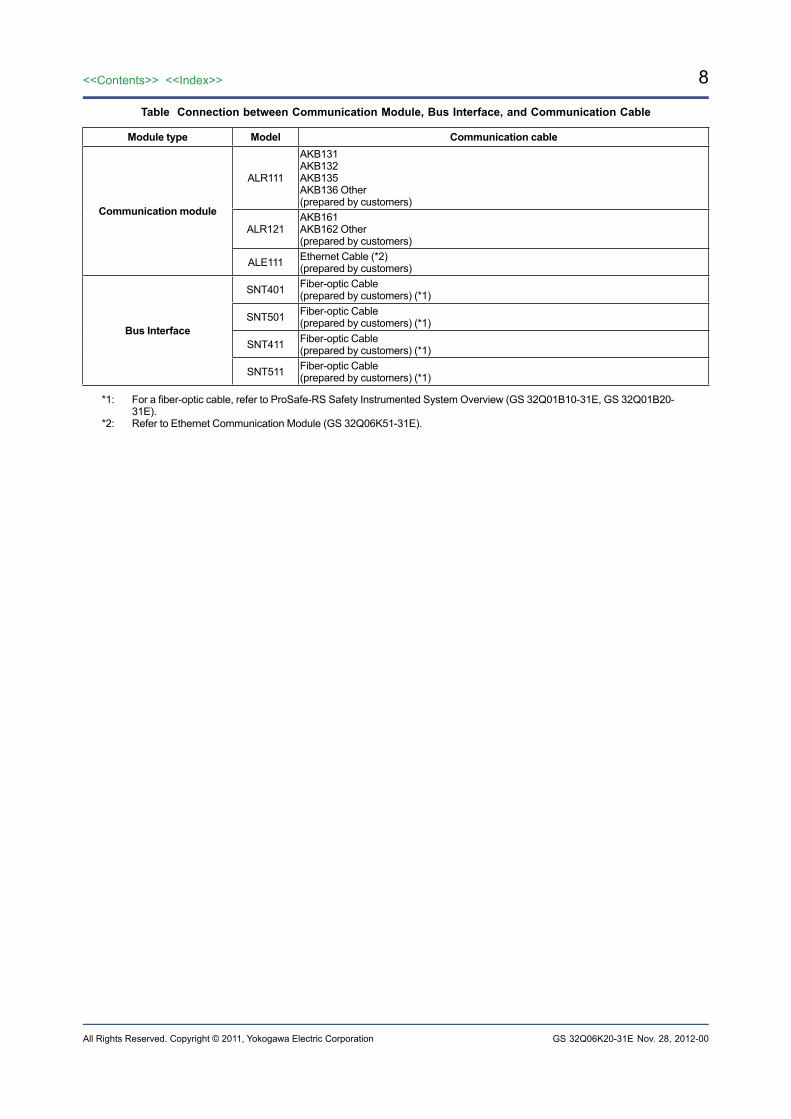
Table Connection between Communication Module, Bus Interface, and Communication Cable
Module type Model Communication cable
Communication module
ALR111
AKB131AKB132AKB135AKB136 Other (prepared by customers)
ALR121AKB161AKB162 Other (prepared by customers)
ALE111 Ethernet Cable (*2)(prepared by customers)
Bus Interface
SNT401 Fiber-optic Cable(prepared by customers) (*1)
SNT501 Fiber-optic Cable(prepared by customers) (*1)
SNT411 Fiber-optic Cable(prepared by customers) (*1)
SNT511 Fiber-optic Cable(prepared by customers) (*1)
*1: For a fiber-optic cable, refer to ProSafe-RS Safety Instrumented System Overview (GS 32Q01B10-31E, GS 32Q01B20-31E).
*2: Refer to Ethernet Communication Module (GS 32Q06K51-31E).
Nov. 28, 2012-00
9<<Contents>> <<Index>>
All Rights Reserved. Copyright © 2011, Yokogawa Electric Corporation GS 32Q06K20-31E
Current Consumption of I/O Modules
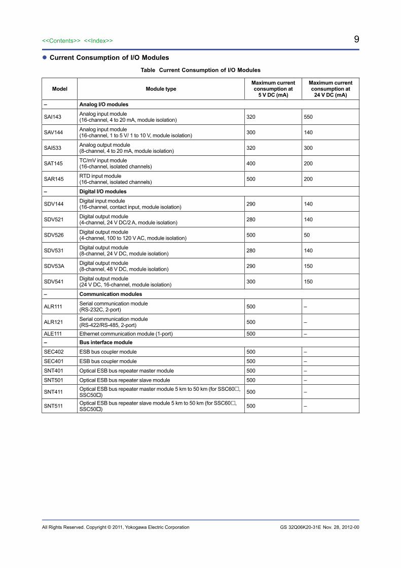
Table Current Consumption of I/O Modules
Model Module typeMaximum current consumption at
5 V DC (mA)
Maximum current consumption at
24 V DC (mA)
– Analog I/O modules
SAI143 Analog input module (16-channel, 4 to 20 mA, module isolation) 320 550
SAV144 Analog input module (16-channel, 1 to 5 V/ 1 to 10 V, module isolation) 300 140
SAI533 Analog output module (8-channel, 4 to 20 mA, module isolation) 320 300
SAT145 TC/mV input module(16-channel, isolated channels) 400 200
SAR145 RTD input module(16-channel, isolated channels) 500 200
– Digital I/O modules
SDV144 Digital input module (16-channel, contact input, module isolation) 290 140
SDV521 Digital output module (4-channel, 24 V DC/2 A, module isolation) 280 140
SDV526 Digital output module (4-channel, 100 to 120 V AC, module isolation) 500 50
SDV531 Digital output module (8-channel, 24 V DC, module isolation) 280 140
SDV53A Digital output module (8-channel, 48 V DC, module isolation) 290 150
SDV541 Digital output module (24 V DC, 16-channel, module isolation) 300 150
– Communication modules
ALR111 Serial communication module (RS-232C, 2-port) 500 –
ALR121 Serial communication module(RS-422/RS-485, 2-port) 500 –
ALE111 Ethernet communication module (1-port) 500 –– Bus interface module
SEC402 ESB bus coupler module 500 –
SEC401 ESB bus coupler module 500 –
SNT401 Optical ESB bus repeater master module 500 –
SNT501 Optical ESB bus repeater slave module 500 –
SNT411 Optical ESB bus repeater master module 5 km to 50 km (for SSC60, SSC50) 500 –
SNT511 Optical ESB bus repeater slave module 5 km to 50 km (for SSC60, SSC50) 500 –
Nov. 28, 2012-00

10
All Rights Reserved. Copyright © 2011, Yokogawa Electric Corporation
<<Contents>> <<Index>>
GS 32Q06K20-31E
NODE UNIT MOUNTING RESTRICTIONS For Ambient Temperature 60 °C or Lower[Power supply capacity limitation]Up to eight modules per unit can be mounted on SNB10D safety node unit and SSC60/SSC50/SSC10 safety control unit; however, the number differs by power supply capacity. Use the Table “Coefficients of Module (temperature type)” to calculate the sum of Coefficient A and B, and figure out the number that both ∑(coefficient A) + ∑(coefficient B) and ∑(coefficient B) are satisfied within the value shown in the Table “ Power Supply Capacity Limitation (temperature type, 60°C or lower)”. The values shown in the Table “Power Supply Capacity Limitation (temperature type, 60°C or lower)” differ by the installation environments such as for standard installation and explosion protection.
Table Coefficients of Module (temperature type)
ModelCoefficient A Coefficient B
Single Dual redundant Single Dual redundant
SAI143-H3 (2-wire setting) 3 6 25 29
SAI143-H3 (4-wire setting) 3 6 5 10
SAI143-S3 (2-wire setting) 3 5 22 25
SAI143-S3 (4-wire setting) 3 5 4 7
SAI533-H3 3 6 12 23
SAV144-S3 3 5 2 4
SAT145-S33 5 8 8 16
SAR145-S33 5 9 8 16
SDV144-S3 2 4 2 4
SDV521-S33 2 4 2 4
SDV526-S33 5 10 3 5
SDV531-L3 2 4 2 4
SDV53A-S33 2 4 3 5
SDV541-S3 3 6 5 7
Other (*1) 5 10 0 0
*1: SEC401, SEC402, SNT401, SNT501, SNT411, SNT511, ALR111, ALR121, ALE111
Table Power Supply Capacity Limitation (temperature type, 60°C or lower)
Model Installation environment Ambient temperature (°C)
Σ(coefficient A) +Σ(coefficient B) Σ(coefficient B)
SNB10D
Standard installations -20 ≤ Ta ≤ 60 – ≤ 100
For FM NI and Type n installation in Class I, Division 2/Zone 2 area:
-20 ≤ Ta ≤ 50 – ≤ 100
-20 ≤ Ta ≤ 60 – ≤ 88
SSC60S SSC50S SSC10S
Standard installations -20 ≤ Ta ≤ 60 ≤ 121 ≤ 85
For FM NI and Type n installation in Class I, Division 2/Zone 2 area: -20 ≤ Ta ≤ 60 ≤ 121 ≤ 85
SSC60D SSC50D SSC10D
Standard installations -20 ≤ Ta ≤ 60 ≤ 97 ≤ 85
For FM NI and Type n installation in Class I, Division 2/Zone 2 area: -20 ≤ Ta ≤ 60 ≤ 97 ≤ 85
Nov. 28, 2012-00
11<<Contents>> <<Index>>
All Rights Reserved. Copyright © 2011, Yokogawa Electric Corporation GS 32Q06K20-31E
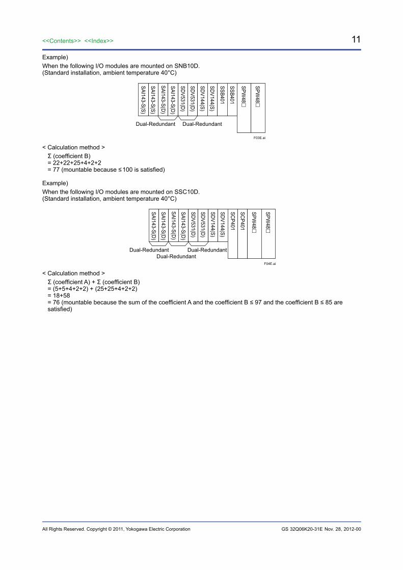
Example)When the following I/O modules are mounted on SNB10D. (Standard installation, ambient temperature 40°C)
F03E.ai
SAI143-S(S)
SAI143-S(S)
SAI143-S(D)
SAI143-S(D)
SDV531(D)
SDV531(D)
SDV144(S)
SDV144(S)
SSB401
SSB401
SPW48
SPW48
Dual-Redundant Dual-Redundant
< Calculation method >Σ (coefficient B)= 22+22+25+4+2+2= 77 (mountable because ≤ 100 is satisfied)
Example)When the following I/O modules are mounted on SSC10D. (Standard installation, ambient temperature 40°C)
F04E.ai
SAI143-S(D)
SAI143-S(D)
SAI143-S(D)
SAI143-S(D)
SDV531(D)
SDV531(D)
SDV144(S)
SDV144(S)
SCP401
SCP401
SPW48
SPW48
Dual-Redundant Dual-RedundantDual-Redundant
< Calculation method >Σ (coefficient A) + Σ (coefficient B)= (5+5+4+2+2) + (25+25+4+2+2)= 18+58= 76 (mountable because the sum of the coefficient A and the coefficient B ≤ 97 and the coefficient B ≤ 85 are satisfied)
Nov. 28, 2012-00
12
All Rights Reserved. Copyright © 2011, Yokogawa Electric Corporation
<<Contents>> <<Index>>
GS 32Q06K20-31E
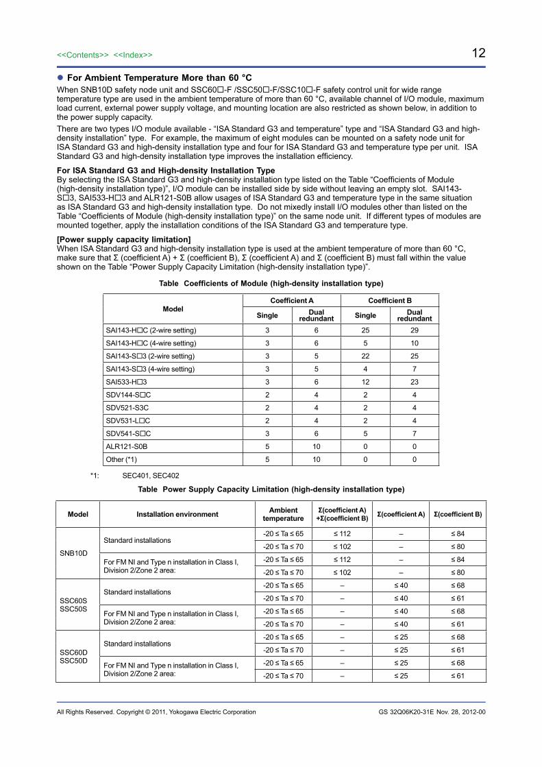
For Ambient Temperature More than 60 °CWhen SNB10D safety node unit and SSC60-F /SSC50-F/SSC10-F safety control unit for wide range temperature type are used in the ambient temperature of more than 60 °C, available channel of I/O module, maximum load current, external power supply voltage, and mounting location are also restricted as shown below, in addition to the power supply capacity. There are two types I/O module available - “ISA Standard G3 and temperature” type and “ISA Standard G3 and high-density installation” type. For example, the maximum of eight modules can be mounted on a safety node unit for ISA Standard G3 and high-density installation type and four for ISA Standard G3 and temperature type per unit. ISA Standard G3 and high-density installation type improves the installation efficiency.
For ISA Standard G3 and High-density Installation TypeBy selecting the ISA Standard G3 and high-density installation type listed on the Table “Coefficients of Module (high-density installation type)”, I/O module can be installed side by side without leaving an empty slot. SAI143-S3, SAI533-H3 and ALR121-S0B allow usages of ISA Standard G3 and temperature type in the same situation as ISA Standard G3 and high-density installation type. Do not mixedly install I/O modules other than listed on the Table “Coefficients of Module (high-density installation type)” on the same node unit. If different types of modules are mounted together, apply the installation conditions of the ISA Standard G3 and temperature type.
[Power supply capacity limitation]When ISA Standard G3 and high-density installation type is used at the ambient temperature of more than 60 °C, make sure that Σ (coefficient A) + Σ (coefficient B), Σ (coefficient A) and Σ (coefficient B) must fall within the value shown on the Table “Power Supply Capacity Limitation (high-density installation type)”.
Table Coefficients of Module (high-density installation type)
ModelCoefficient A Coefficient B
Single Dual redundant Single Dual
redundantSAI143-HC (2-wire setting) 3 6 25 29
SAI143-HC (4-wire setting) 3 6 5 10
SAI143-S3 (2-wire setting) 3 5 22 25
SAI143-S3 (4-wire setting) 3 5 4 7
SAI533-H3 3 6 12 23
SDV144-SC 2 4 2 4
SDV521-S3C 2 4 2 4
SDV531-LC 2 4 2 4
SDV541-SC 3 6 5 7
ALR121-S0B 5 10 0 0
Other (*1) 5 10 0 0
*1: SEC401, SEC402
Table Power Supply Capacity Limitation (high-density installation type)
Model Installation environment Ambient temperature
Σ(coefficient A) +Σ(coefficient B) Σ(coefficient A) Σ(coefficient B)
SNB10D
Standard installations-20 ≤ Ta ≤ 65 ≤ 112 – ≤ 84
-20 ≤ Ta ≤ 70 ≤ 102 – ≤ 80
For FM NI and Type n installation in Class I, Division 2/Zone 2 area:
-20 ≤ Ta ≤ 65 ≤ 112 – ≤ 84
-20 ≤ Ta ≤ 70 ≤ 102 – ≤ 80
SSC60S SSC50S
Standard installations-20 ≤ Ta ≤ 65 – ≤ 40 ≤ 68
-20 ≤ Ta ≤ 70 – ≤ 40 ≤ 61
For FM NI and Type n installation in Class I, Division 2/Zone 2 area:
-20 ≤ Ta ≤ 65 – ≤ 40 ≤ 68
-20 ≤ Ta ≤ 70 – ≤ 40 ≤ 61
SSC60D SSC50D
Standard installations-20 ≤ Ta ≤ 65 – ≤ 25 ≤ 68
-20 ≤ Ta ≤ 70 – ≤ 25 ≤ 61
For FM NI and Type n installation in Class I, Division 2/Zone 2 area:
-20 ≤ Ta ≤ 65 – ≤ 25 ≤ 68
-20 ≤ Ta ≤ 70 – ≤ 25 ≤ 61
Nov. 28, 2012-00
13<<Contents>> <<Index>>
All Rights Reserved. Copyright © 2011, Yokogawa Electric Corporation GS 32Q06K20-31E
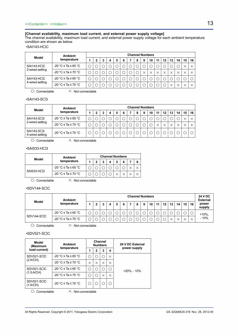
[Channel availability, maximum load current, and external power supply voltage]The channel availability, maximum load current, and external power supply voltage for each ambient temperature condition are shown as below.•SAI143-HC
Model Ambient temperature
Channel Numbers1 2 3 4 5 6 7 8 9 10 11 12 13 14 15 16
SAI143-HC2-wired setting
-20 °C ≤ Ta ≤ 65 °C
-20 °C ≤ Ta ≤ 70 °C
SAI143-HC4-wired setting
-20 °C ≤ Ta ≤ 65 °C
-20 °C ≤ Ta ≤ 70 °C
: Connectable : Not connectable
•SAI143-S3
Model Ambient temperature
Channel Numbers1 2 3 4 5 6 7 8 9 10 11 12 13 14 15 16
SAI143-S32-wired setting
-20 °C ≤ Ta ≤ 65 °C
-20 °C ≤ Ta ≤ 70 °C
SAI143-S34-wired setting -20 °C ≤ Ta ≤ 70 °C
: Connectable : Not connectable
•SAI533-H3
Model Ambient temperature
Channel Numbers1 2 3 4 5 6 7 8
SAI533-H3-20 °C ≤ Ta ≤ 65 °C
-20 °C ≤ Ta ≤ 70 °C
: Connectable : Not connectable
•SDV144-SC
Model Ambient temperature
Channel Numbers 24 V DC External power supply
1 2 3 4 5 6 7 8 9 10 11 12 13 14 15 16
SDV144-SC-20 °C ≤ Ta ≤ 65 °C +10%,
- 10%-20 °C ≤ Ta ≤ 70 °C
: Connectable : Not connectable
•SDV521-SC
Model (Maximum
load current)Ambient
temperature
Channel Numbers 24 V DC External
power supply1 2 3 4
SDV521-SC(2 A/CH)
-20 °C ≤ Ta ≤ 65 °C
+20%, - 10%
-20 °C ≤ Ta ≤ 70 °C
SDV521-SC(1.5 A/CH)
-20 °C ≤ Ta ≤ 65 °C
-20 °C ≤ Ta ≤ 70 °C
SDV521-SC(1 A/CH) -20 °C ≤ Ta ≤ 70 °C
: Connectable : Not connectable
Nov. 28, 2012-00
14
All Rights Reserved. Copyright © 2011, Yokogawa Electric Corporation
<<Contents>> <<Index>>
GS 32Q06K20-31E
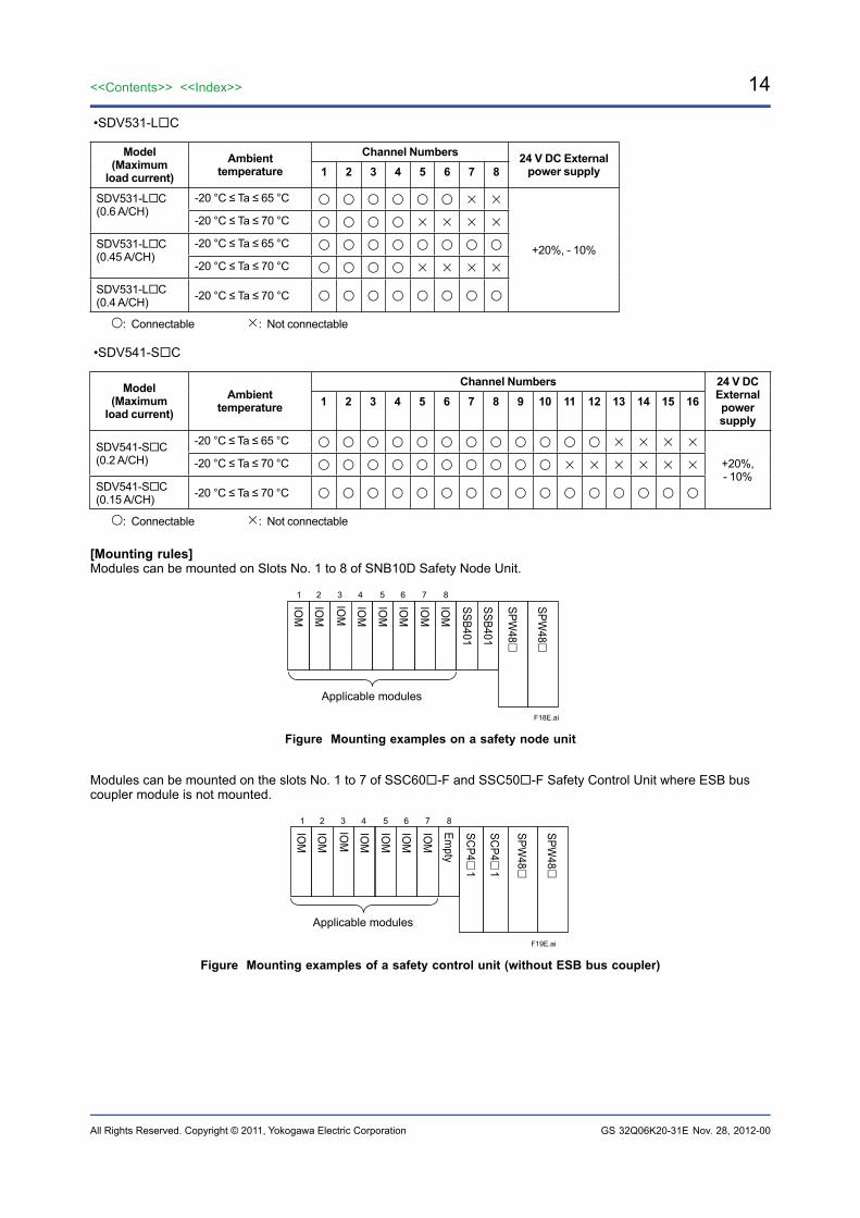
•SDV531-LC
Model (Maximum
load current)Ambient
temperatureChannel Numbers 24 V DC External
power supply1 2 3 4 5 6 7 8
SDV531-LC(0.6 A/CH)
-20 °C ≤ Ta ≤ 65 °C
+20%, - 10%
-20 °C ≤ Ta ≤ 70 °C
SDV531-LC(0.45 A/CH)
-20 °C ≤ Ta ≤ 65 °C
-20 °C ≤ Ta ≤ 70 °C
SDV531-LC(0.4 A/CH) -20 °C ≤ Ta ≤ 70 °C
: Connectable : Not connectable
•SDV541-SC
Model (Maximum
load current)Ambient
temperature
Channel Numbers 24 V DC External power supply
1 2 3 4 5 6 7 8 9 10 11 12 13 14 15 16
SDV541-SC(0.2 A/CH)
-20 °C ≤ Ta ≤ 65 °C
+20%,- 10%
-20 °C ≤ Ta ≤ 70 °C
SDV541-SC(0.15 A/CH) -20 °C ≤ Ta ≤ 70 °C
: Connectable : Not connectable
[Mounting rules]Modules can be mounted on Slots No. 1 to 8 of SNB10D Safety Node Unit.
F18E.ai
IOM
IOM
IOM
IOM
IOM
IOM
IOM
IOM
SSB401
SSB401
SPW48
SPW48
Applicable modules
1 2 3 4 5 6 7 8
Figure Mounting examples on a safety node unit
Modules can be mounted on the slots No. 1 to 7 of SSC60-F and SSC50-F Safety Control Unit where ESB bus coupler module is not mounted.
F19E.ai
IOM
IOM
IOM
IOM
IOM
IOM
IOM
SCP4
1
SCP4
1
SPW48
SPW48
Applicable modules
1 2 3 4 5 6 7 8
Empty
Figure Mounting examples of a safety control unit (without ESB bus coupler)
Nov. 28, 2012-00
15<<Contents>> <<Index>>
All Rights Reserved. Copyright © 2011, Yokogawa Electric Corporation GS 32Q06K20-31E
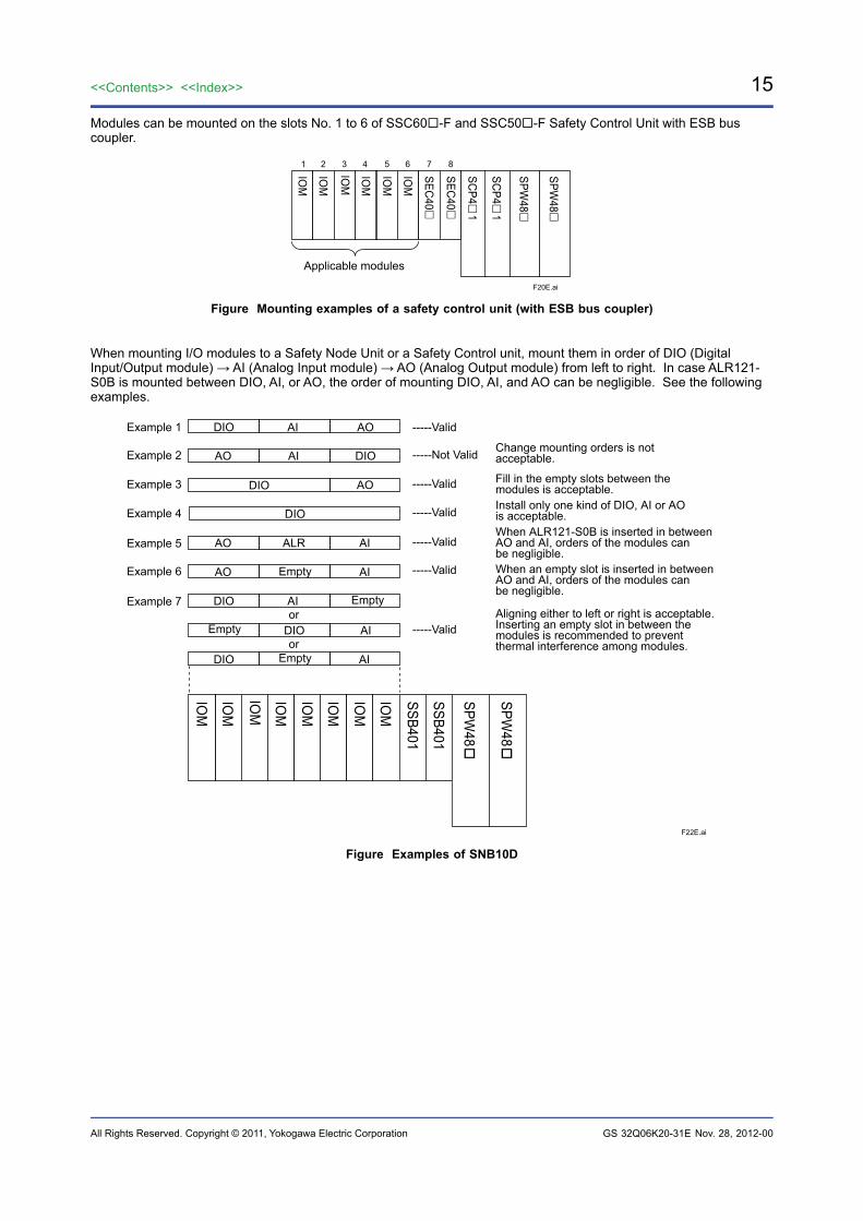
Modules can be mounted on the slots No. 1 to 6 of SSC60-F and SSC50-F Safety Control Unit with ESB bus coupler.
F20E.ai
IOM
IOM
IOM
IOM
IOM
IOM
SEC40
SCP4
1
SEC40
SCP4
1
SPW48
SPW48
Applicable modules
1 2 3 4 5 6 7 8
Figure Mounting examples of a safety control unit (with ESB bus coupler)
When mounting I/O modules to a Safety Node Unit or a Safety Control unit, mount them in order of DIO (Digital Input/Output module) → AI (Analog Input module) → AO (Analog Output module) from left to right. In case ALR121-S0B is mounted between DIO, AI, or AO, the order of mounting DIO, AI, and AO can be negligible. See the following examples.
F22E.ai
IOM
IOM
IOM
IOM
IOM
IOM
IOM
IOM
SSB401
SSB401
SPW48
SPW48
AO
ALR
AO
AO
AO
AO
AI
AI
AI
AI
AI
AI
AI
DIO
DIO
DIO
DIOor
orDIO
DIOAligning either to left or right is acceptable. Inserting an empty slot in between the modules is recommended to prevent thermal interference among modules.
When an empty slot is inserted in between AO and AI, orders of the modules can be negligible.
When ALR121-S0B is inserted in between AO and AI, orders of the modules can be negligible.
Install only one kind of DIO, AI or AO is acceptable.
Fill in the empty slots between the modules is acceptable.
Change mounting orders is not acceptable.-----Not Valid
-----Valid
-----Valid
-----Valid
-----Valid
-----Valid
-----ValidExample 1
Example 2
Example 3
Example 4
Example 5
Example 6
Example 7
DIO
Empty
Empty
Empty
Empty
Figure Examples of SNB10D
Nov. 28, 2012-00
16
All Rights Reserved. Copyright © 2011, Yokogawa Electric Corporation
<<Contents>> <<Index>>
GS 32Q06K20-31E
For ISA Standard G3 and Temperature TypeWhen using I/O modules other than the ones listed on the Table “Coefficients of Module (high-density installation type)”, select ISA Standard G3 and temperature type which meets the following conditions.
[Power supply capacity limitation]Refer to the Table “Coefficients of Module (temperature type)” to find the sum of Coefficient A and B assigned to the module and then make sure that Σ (coefficient A) + Σ (coefficient B) and Σ (coefficient B) satisfy the value on the Table “Power Supply Capacity Limitation (temperature type, more than 60°C)”.
Table Power Supply Capacity Limitation (temperature type, more than 60°C)
Model Installation environment Ambient temperature (°C)
Σ(coefficient A) +Σ(coefficient B) Σ(coefficient B)
SNB10DStandard installations -20 ≤ Ta ≤ 70 – ≤ 100
For FM NI and Type n installation in Class I, Division 2/Zone 2 area: -20 ≤ Ta ≤ 70 – ≤ 80
SSC60S SSC50S SSC10S
Standard installations -20 ≤ Ta ≤ 70 ≤ 121 ≤ 85
For FM NI and Type n installation in Class I, Division 2/Zone 2 area: -20 ≤ Ta ≤ 70 ≤ 121 ≤ 80
SSC60D SSC50D SSC10D
Standard installations -20 ≤ Ta ≤ 70 ≤ 97 ≤ 85
For FM NI and Type n installation in Class I, Division 2/Zone 2 area: -20 ≤ Ta ≤ 70 ≤ 97 ≤ 80
[Channel availability, maximum load current, and external power supply voltage]No specific condition.
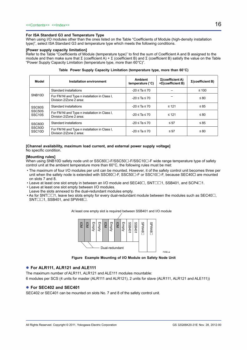
[Mounting rules]When using SNB10D safety node unit or SSC60-F/SSC50-F/SSC10-F wide range temperature type of safety control unit at the ambient temperature more than 60°C, the following rules must be met:• The maximum of four I/O modules per unit can be mounted. However, it of the safety control unit becomes three per
unit when the safety node is extended with SSC60-F, SSC50-F or SSC10-F, because SEC40 are mounted on slots 7 and 8.
• Leave at least one slot empty in between an I/O module and SEC40, SNT1, SSB401, and SCP41.• Leave at least one slot empty between I/O modules. Leave the slots annexed to the dual-redundant modules empty.• As for SNT1, leave two slots empty for every dual-redundant module between the modules such as SEC40,
SNT1, SSB401, and SPW48.
F05E.ai
IOM
IOM
IOM
IOM
SSB401
SSB401
SPW48
SPW48
At least one empty slot is required between SSB401 and I/O module
Dual-redundant
Em
pty
Em
pty
Em
pty
Em
pty
Figure Example Mounting of I/O Module on Safety Node Unit
For ALR111, ALR121 and ALE111The maximum number of ALR111, ALR121 and ALE111 modules mountable:6 modules per SCS (4 units for master (ALR111 and ALR121), 2 units for slave (ALR111, ALR121 and ALE111))
For SEC402 and SEC401SEC402 or SEC401 can be mounted on slots No. 7 and 8 of the safety control unit.
Nov. 28, 2012-00
17<<Contents>> <<Index>>
All Rights Reserved. Copyright © 2011, Yokogawa Electric Corporation GS 32Q06K20-31E
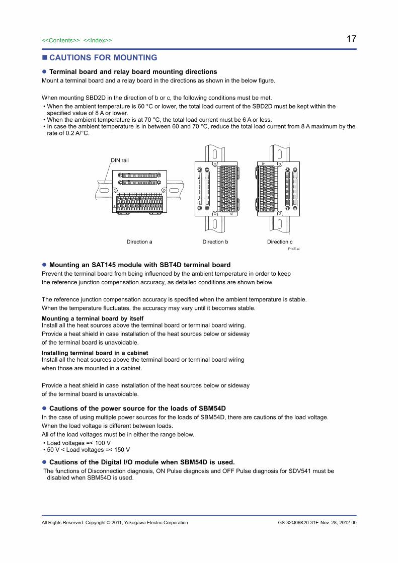
CAUTIONS FOR MOUNTING Terminal board and relay board mounting directionsMount a terminal board and a relay board in the directions as shown in the below figure.
When mounting SBD2D in the direction of b or c, the following conditions must be met.• When the ambient temperature is 60 °C or lower, the total load current of the SBD2D must be kept within the
specified value of 8 A or lower.• When the ambient temperature is at 70 °C, the total load current must be 6 A or less.• In case the ambient temperature is in between 60 and 70 °C, reduce the total load current from 8 A maximum by the
rate of 0.2 A/°C.
F14E.ai
DIN rail
Direction a Direction b Direction c
Mounting an SAT145 module with SBT4D terminal boardPrevent the terminal board from being influenced by the ambient temperature in order to keep the reference junction compensation accuracy, as detailed conditions are shown below.
The reference junction compensation accuracy is specified when the ambient temperature is stable. When the temperature fluctuates, the accuracy may vary until it becomes stable.
Mounting a terminal board by itselfInstall all the heat sources above the terminal board or terminal board wiring.Provide a heat shield in case installation of the heat sources below or sideway of the terminal board is unavoidable.
Installing terminal board in a cabinetInstall all the heat sources above the terminal board or terminal board wiring when those are mounted in a cabinet.
Provide a heat shield in case installation of the heat sources below or sideway of the terminal board is unavoidable.
Cautions of the power source for the loads of SBM54DIn the case of using multiple power sources for the loads of SBM54D, there are cautions of the load voltage.When the load voltage is different between loads.All of the load voltages must be in either the range below. • Load voltages =< 100 V • 50 V < Load voltages =< 150 V
Cautions of the Digital I/O module when SBM54D is used.The functions of Disconnection diagnosis, ON Pulse diagnosis and OFF Pulse diagnosis for SDV541 must be
disabled when SBM54D is used.
Nov. 28, 2012-00
18
All Rights Reserved. Copyright © 2011, Yokogawa Electric Corporation
<<Contents>> <<Index>>
GS 32Q06K20-31E
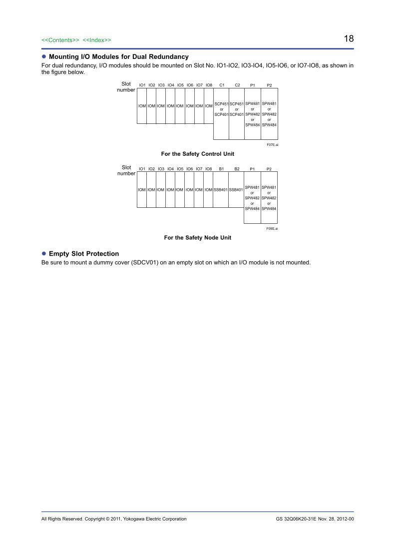
Mounting I/O Modules for Dual RedundancyFor dual redundancy, I/O modules should be mounted on Slot No. IO1-IO2, IO3-IO4, IO5-IO6, or IO7-IO8, as shown in the figure below.
IO1
IOM IOM IOM IOM IOM IOM IOM IOM SCP451or
SCP401
SCP451or
SCP401
SPW481or
SPW482or
SPW484
SPW481or
SPW482or
SPW484
IO2 IO3 IO4 IO5 IO6 IO7 IO8 C1 C2 P1 P2
F07E.ai
Slotnumber
For the Safety Control Unit
IO1
IOM IOM IOM IOM IOM IOM IOM IOM SSB401SSB401 SPW481or
SPW482or
SPW484
SPW481or
SPW482or
SPW484
IO2 IO3 IO4 IO5 IO6 IO7 IO8 B1 B2 P1 P2
F06E.ai
Slotnumber
For the Safety Node Unit
Empty Slot ProtectionBe sure to mount a dummy cover (SDCV01) on an empty slot on which an I/O module is not mounted.
Nov. 28, 2012-00

19<<Contents>> <<Index>>
All Rights Reserved. Copyright © 2011, Yokogawa Electric Corporation GS 32Q06K20-31E
LIMITATIONS ON DIGITAL INPUT MODULE CONNECTIONSDigital input incorporates input wiring diagnostic functions. Where a pulse test is enabled, it is necessary to take into account the following conditions for the length of the field wiring cable.
If Pulse Test is UsedThe total value of the capacitance of the field devices connected to the digital input modules and their wiring cable capacitance should be:
Total capacitance < 0.1 µF (100000 pF)
Note: Wiring capacitance from pressure clamp terminal block or terminal board to the field device depends on the cable type such as Discrete wire or Multi-core cable. Make sure the specification of cable.
Note: Calculate the total capacitance of an AKB331 cable with a capacitance of 60 pF/m.Note: It is not necessary to take into account the capacitance of pressure clamp terminal block, terminal boards, or signal cable
adapters.
[References]For terminal board connections, if the AKB331 cable is 15 m long, the distance between the terminal board and field device is 500 m, the capacitance of the cables is 100 pF/m, and the capacitance of the field devices is 0 pF then
the total wiring capacitance = 15 (m) × 60 (pF/m) + 500 (m) × 100 (pF/m) + 0 (pF) = 50900 (pF) < 100000 (pF)
From this calculation, pulse test can work properly.
If SCB110 Wiring Check Adapters are UsedTo get digital input modules to recognize an ON input signal correctly, the total resistance of field devices and their wiring cables is no greater than 132 Ω.If no SCB110 wiring check adapters are used, the cables connecting the digital input module and the field devices should be limited in length so that the total resistance of all the connected field devices and cables is no greater than 1 kΩ.
Note: It is not necessary to take into account the resistance of pressure clamp terminals, terminal boards, signal cable adapters, and wiring check adapters (SCB100/SCB110).
The following table shows AKB331 cable lengths and allowable resistance on the field side if AKB331 cables are used.
AKB331 cable length, m Resistance allowed on the field side, Ω
0 132
10 120
20 109
30 98
40 87
50 75
[References]For example, if the AKB331 cable length is 10 meters and the resistance of field device ON is 20 Ω, the allowable wiring resistance is then:
120 Ω – 20 Ω = 100 Ω
The cable length, both from and to field devices if the cables have a wiring resistance of 58 Ω/km (AWG22 equivalent), is:
100 Ω / 0.058 Ω/m ≈ 1724 (m)
Hence, the distance to the field devices is:1724 (m) / 2 = 862 (m)
Note: For cable resistances, refer to the cable manufacturer’s specifications.
Nov. 28, 2012-00

20
All Rights Reserved. Copyright © 2011, Yokogawa Electric Corporation
<<Contents>> <<Index>>
GS 32Q06K20-31E
LIMITATIONS ON DIGITAL OUTPUT MODULE CONNECTIONSDigital output modules incorporate output wiring diagnostic functions. Where a pulse test is enabled, it is necessary to take into account the following conditions for the length of the field wiring cable.The total value of the capacitance of the field devices connected to the digital input and output modules and their wiring cable capacitance should be:
Total capacitance < 0.1 µF (100000 pF)
Note: Wiring capacitance from pressure clamp terminal block or terminal board to the field device depends on the cable type such as Discrete wire or Multi-core cable. Make sure the specification of cable.
Note: Calculate the total capacitance of an AKB331 cable with a capacitance of 60 pF/m.Note: Calculate the total capacitance of an AKB651 cable with a capacitance of 200 pF/m.Note: It is not necessary to take into account the capacitance of pressure clamp terminal block, terminal boards, or signal cable
adapters.
[References]For terminal board connections, if the AKB331 cable is 15 m long, the distance between the terminal board and field device is 500 m, the capacitance of the cables is 100 pF/m, and the capacitance of the field devices is 0 pF then
the total wiring capacitance = 15 (m) × 60 (pF/m) + 500 (m) × 100 (pF/m) + 0 (pF) = 50900 (pF) < 100000 (pF)
From this calculation, pulse test can work properly.
When digital output modules are connected with terminal boards, MIL connecters or pressure clamp terminals, due to the voltage drop on the field wirings, the length of field wirings have restrictions as follows.
Nov. 28, 2012-00

21<<Contents>> <<Index>>
All Rights Reserved. Copyright © 2011, Yokogawa Electric Corporation GS 32Q06K20-31E
SDV531Terminal Board is ConnectedThe SDV531 digital output module can respectively handle a maximum of 0.6 A load currents per channel. However, this can cause the generation of a voltage drop due to connected cable and adapter resistance components, etc. Therefore, it is necessary to take account of the limitations on the magnitude of load current and connected cable length as given below.
In case of short circuits detection is enabled, the possible cable length may be limited.
Outputvoltage
drop1 [V]
F11E.ai
Digital OutputModule
TerminalBoard
Signal Cable
Adapter
Connector
TM1
TM2 (*1)
24 V DC
COM
User Cable (for power) length Lp [m]
Rp
Rp
Vp
Load OUTn (n=1~8)
COMn (n=1~8)
VLn
RS
RS
User Cable (for signal) length Ls [m]
1 to 8 channelsIsn
Otherresistancecomponent
(*2)
Cableresistance (*3)Rcs (for signal)Rcp (for power)
Ip∑
Connector
L [m]
1 to 8 channels
*1: TM1 only for SBD3D*2: Other resistance component is given below:
Table Other resistance component vs. Terminal board
Terminal board model No.
Connectionmodule model No.
Other resistance component [mΩ] (By 1 channel)
Signal PowerSED4D SDV531 202.8 56.36
SBD3D SDV531 222.1 34.72
*3: Cable resistance is given below:
Table Signal cable vs. Cable resistance
Signal cablemodel No.
Cable resistance [mΩ/m]
Rcs (for signal) Rcp (for power)AKB331 446.0 63.71
AKB651 118.6 16.94
Nov. 28, 2012-00
22
All Rights Reserved. Copyright © 2011, Yokogawa Electric Corporation
<<Contents>> <<Index>>
GS 32Q06K20-31E
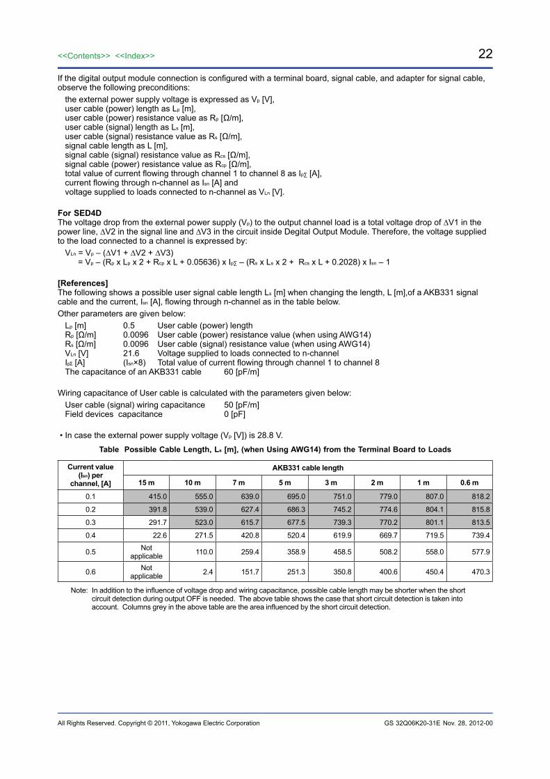
If the digital output module connection is configured with a terminal board, signal cable, and adapter for signal cable, observe the following preconditions:
the external power supply voltage is expressed as Vp [V],user cable (power) length as Lp [m],user cable (power) resistance value as Rp [Ω/m],user cable (signal) length as Ls [m],user cable (signal) resistance value as Rs [Ω/m],signal cable length as L [m],signal cable (signal) resistance value as Rcs [Ω/m],signal cable (power) resistance value as Rcp [Ω/m],total value of current flowing through channel 1 to channel 8 as Ip∑ [A],current flowing through n-channel as Isn [A] andvoltage supplied to loads connected to n-channel as VLn [V].
For SED4DThe voltage drop from the external power supply (Vp) to the output channel load is a total voltage drop of ∆V1 in the power line, ∆V2 in the signal line and ∆V3 in the circuit inside Degital Output Module. Therefore, the voltage supplied to the load connected to a channel is expressed by:
VLn = Vp – (∆V1 + ∆V2 + ∆V3) = Vp – (Rp x Lp x 2 + Rcp x L + 0.05636) x Ip∑ – (Rs x Ls x 2 + Rcs x L + 0.2028) x Isn – 1
[References]The following shows a possible user signal cable length Ls [m] when changing the length, L [m],of a AKB331 signal cable and the current, Isn [A], flowing through n-channel as in the table below.Other parameters are given below:
Lp [m] 0.5 User cable (power) lengthRp [Ω/m] 0.0096 User cable (power) resistance value (when using AWG14)Rs [Ω/m] 0.0096 User cable (signal) resistance value (when using AWG14)VLn [V] 21.6 Voltage supplied to loads connected to n-channelIp [A] (Isn×8) Total value of current flowing through channel 1 to channel 8 The capacitance of an AKB331 cable 60 [pF/m]
Wiring capacitance of User cable is calculated with the parameters given below:User cable (signal) wiring capacitance 50 [pF/m]Field devices capacitance 0 [pF]
• In case the external power supply voltage (Vp [V]) is 28.8 V.
Table Possible Cable Length, Ls [m], (when Using AWG14) from the Terminal Board to Loads
Current value (Isn) per
channel, [A]
AKB331 cable length
15 m 10 m 7 m 5 m 3 m 2 m 1 m 0.6 m
0.1 415.0 555.0 639.0 695.0 751.0 779.0 807.0 818.2
0.2 391.8 539.0 627.4 686.3 745.2 774.6 804.1 815.8
0.3 291.7 523.0 615.7 677.5 739.3 770.2 801.1 813.5
0.4 22.6 271.5 420.8 520.4 619.9 669.7 719.5 739.4
0.5 Not applicable 110.0 259.4 358.9 458.5 508.2 558.0 577.9
0.6 Not applicable 2.4 151.7 251.3 350.8 400.6 450.4 470.3
Note: In addition to the influence of voltage drop and wiring capacitance, possible cable length may be shorter when the short circuit detection during output OFF is needed. The above table shows the case that short circuit detection is taken into account. Columns grey in the above table are the area influenced by the short circuit detection.
Nov. 28, 2012-00
23<<Contents>> <<Index>>
All Rights Reserved. Copyright © 2011, Yokogawa Electric Corporation GS 32Q06K20-31E
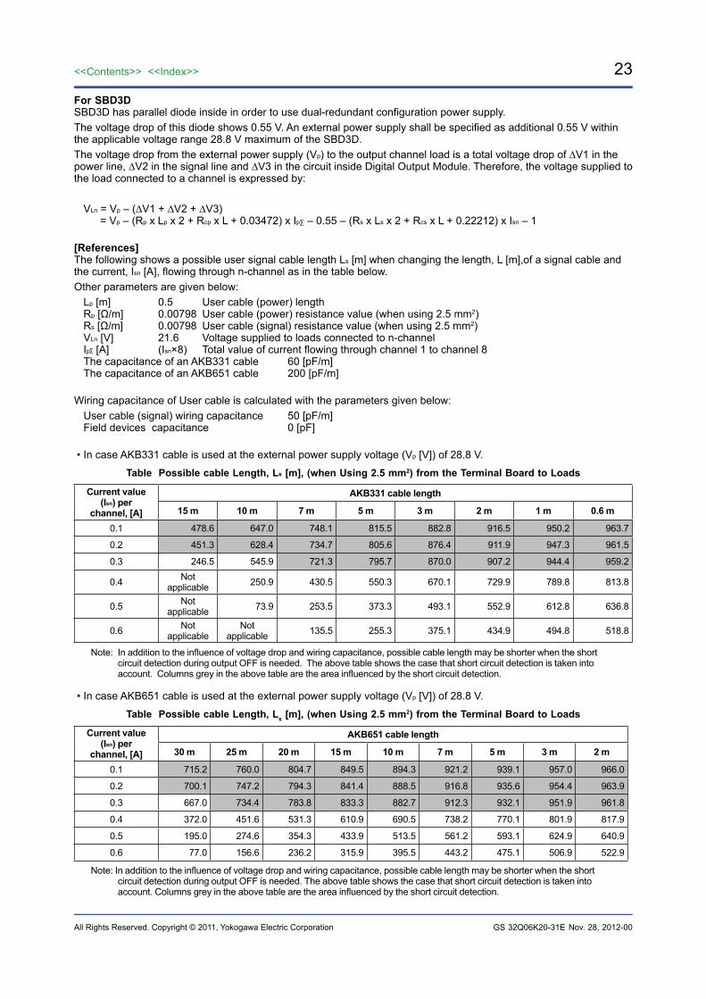
For SBD3DSBD3D has parallel diode inside in order to use dual-redundant configuration power supply.The voltage drop of this diode shows 0.55 V. An external power supply shall be specified as additional 0.55 V within the applicable voltage range 28.8 V maximum of the SBD3D.The voltage drop from the external power supply (Vp) to the output channel load is a total voltage drop of ∆V1 in the power line, ∆V2 in the signal line and ∆V3 in the circuit inside Digital Output Module. Therefore, the voltage supplied to the load connected to a channel is expressed by:
VLn = Vp – (∆V1 + ∆V2 + ∆V3) = Vp – (Rp x Lp x 2 + Rcp x L + 0.03472) x Ip∑ – 0.55 – (Rs x Ls x 2 + Rcs x L + 0.22212) x Isn – 1
[References]The following shows a possible user signal cable length Ls [m] when changing the length, L [m],of a signal cable and the current, Isn [A], flowing through n-channel as in the table below.Other parameters are given below:
Lp [m] 0.5 User cable (power) lengthRp [Ω/m] 0.00798 User cable (power) resistance value (when using 2.5 mm2)Rs [Ω/m] 0.00798 User cable (signal) resistance value (when using 2.5 mm2)VLn [V] 21.6 Voltage supplied to loads connected to n-channelIp [A] (Isn×8) Total value of current flowing through channel 1 to channel 8 The capacitance of an AKB331 cable 60 [pF/m]The capacitance of an AKB651 cable 200 [pF/m]
Wiring capacitance of User cable is calculated with the parameters given below:User cable (signal) wiring capacitance 50 [pF/m]Field devices capacitance 0 [pF]
• In case AKB331 cable is used at the external power supply voltage (Vp [V]) of 28.8 V.
Table Possible cable Length, Ls [m], (when Using 2.5 mm2) from the Terminal Board to Loads
Current value (Isn) per
channel, [A]
AKB331 cable length
15 m 10 m 7 m 5 m 3 m 2 m 1 m 0.6 m
0.1 478.6 647.0 748.1 815.5 882.8 916.5 950.2 963.7
0.2 451.3 628.4 734.7 805.6 876.4 911.9 947.3 961.5
0.3 246.5 545.9 721.3 795.7 870.0 907.2 944.4 959.2
0.4 Not applicable 250.9 430.5 550.3 670.1 729.9 789.8 813.8
0.5 Not applicable 73.9 253.5 373.3 493.1 552.9 612.8 636.8
0.6 Not applicable
Not applicable 135.5 255.3 375.1 434.9 494.8 518.8
Note: In addition to the influence of voltage drop and wiring capacitance, possible cable length may be shorter when the short circuit detection during output OFF is needed. The above table shows the case that short circuit detection is taken into account. Columns grey in the above table are the area influenced by the short circuit detection.
• In case AKB651 cable is used at the external power supply voltage (Vp [V]) of 28.8 V.
Table Possible cable Length, Ls [m], (when Using 2.5 mm2) from the Terminal Board to Loads
Current value (Isn) per
channel, [A]
AKB651 cable length
30 m 25 m 20 m 15 m 10 m 7 m 5 m 3 m 2 m
0.1 715.2 760.0 804.7 849.5 894.3 921.2 939.1 957.0 966.0
0.2 700.1 747.2 794.3 841.4 888.5 916.8 935.6 954.4 963.9
0.3 667.0 734.4 783.8 833.3 882.7 912.3 932.1 951.9 961.8
0.4 372.0 451.6 531.3 610.9 690.5 738.2 770.1 801.9 817.9
0.5 195.0 274.6 354.3 433.9 513.5 561.2 593.1 624.9 640.9
0.6 77.0 156.6 236.2 315.9 395.5 443.2 475.1 506.9 522.9
Note: In addition to the influence of voltage drop and wiring capacitance, possible cable length may be shorter when the short circuit detection during output OFF is needed. The above table shows the case that short circuit detection is taken into account. Columns grey in the above table are the area influenced by the short circuit detection.
Nov. 28, 2012-00
24
All Rights Reserved. Copyright © 2011, Yokogawa Electric Corporation
<<Contents>> <<Index>>
GS 32Q06K20-31E
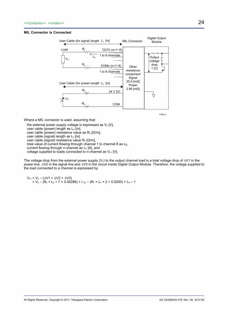
MIL Connector is Connected
F08E.ai
24 V DC
COM
User Cable (for power) length
Load OUTn (n=1~8)
COMn (n=1~8)
VLn
User Cable (for signal) length
Rs
Rs
Isn
Ls [m]
Lp [m]
Rp
Rp
Vp
Digital OutputModuleMIL Connector
Otherresistancecomponent
Signal20.0 [mΩ]
Power2.86 [mΩ]
1 to 8 channels
1 to 8 channels
Outputvoltage
drop1 [V]
Where a MIL connector is used, assuming that:the external power supply voltage is expressed as Vp [V], user cable (power) length as Lp [m], user cable (power) resistance value as Rp [Ω/m], user cable (signal) length as Ls [m], user cable (signal) resistance value Rs [Ω/m], total value of current flowing through channel 1 to channel 8 as Ip∑, current flowing through n-channel as Isn [A], and voltage supplied to loads connected to n-channel as VLn [V].
The voltage drop from the external power supply (Vp) to the output channel load is a total voltage drop of ∆V1 in the power line, ∆V2 in the signal line and ∆V3 in the circuit inside Digital Output Module. Therefore, the voltage supplied to the load connected to a channel is expressed by:
VLn = Vp – (∆V1 + ∆V2 + ∆V3) = Vp – (Rp × Lp ÷ 7 × 0.00286) × I p∑ – (Rs × Ls × 2 + 0.0200) × Isn – 1
Nov. 28, 2012-00
25<<Contents>> <<Index>>
All Rights Reserved. Copyright © 2011, Yokogawa Electric Corporation GS 32Q06K20-31E
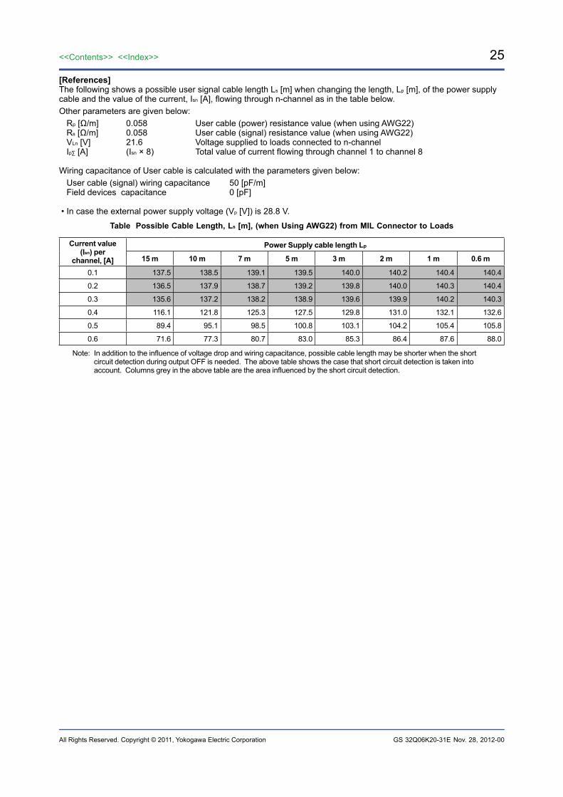
[References]The following shows a possible user signal cable length Ls [m] when changing the length, Lp [m], of the power supply cable and the value of the current, Isn [A], flowing through n-channel as in the table below.Other parameters are given below:
Rp [Ω/m] 0.058 User cable (power) resistance value (when using AWG22)Rs [Ω/m] 0.058 User cable (signal) resistance value (when using AWG22)VLn [V] 21.6 Voltage supplied to loads connected to n-channelIp∑ [A] (Isn × 8) Total value of current flowing through channel 1 to channel 8
Wiring capacitance of User cable is calculated with the parameters given below:User cable (signal) wiring capacitance 50 [pF/m]Field devices capacitance 0 [pF]
• In case the external power supply voltage (Vp [V]) is 28.8 V.
Table Possible Cable Length, Ls [m], (when Using AWG22) from MIL Connector to Loads
Current value (Isn) per
channel, [A]
Power Supply cable length Lp 15 m 10 m 7 m 5 m 3 m 2 m 1 m 0.6 m
0.1 137.5 138.5 139.1 139.5 140.0 140.2 140.4 140.4
0.2 136.5 137.9 138.7 139.2 139.8 140.0 140.3 140.4
0.3 135.6 137.2 138.2 138.9 139.6 139.9 140.2 140.3
0.4 116.1 121.8 125.3 127.5 129.8 131.0 132.1 132.6
0.5 89.4 95.1 98.5 100.8 103.1 104.2 105.4 105.8
0.6 71.6 77.3 80.7 83.0 85.3 86.4 87.6 88.0
Note: In addition to the influence of voltage drop and wiring capacitance, possible cable length may be shorter when the short circuit detection during output OFF is needed. The above table shows the case that short circuit detection is taken into account. Columns grey in the above table are the area influenced by the short circuit detection.
Nov. 28, 2012-00
26
All Rights Reserved. Copyright © 2011, Yokogawa Electric Corporation
<<Contents>> <<Index>>
GS 32Q06K20-31E
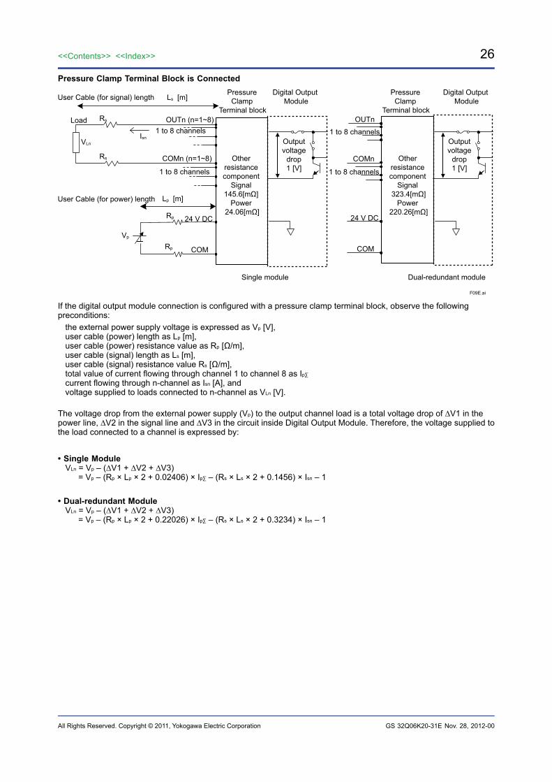
Pressure Clamp Terminal Block is Connected
F09E.ai
Other resistance component
Signal 145.6[mΩ]
Power 24.06[mΩ]
Other resistance component
Signal 323.4[mΩ]
Power 220.26[mΩ]
24 V DC
COM
User Cable (for power) length
Rp
Rp
Load
VLn
User Cable (for signal) length
Rs
Rs
Isn
Vp
Ls [m]
Lp [m]
Single module Dual-redundant module
Digital Output Module
Digital Output Module
Pressure Clamp
Terminal block
Pressure Clamp
Terminal block
24 V DC
COM
OUTn
COMn
1 to 8 channels
1 to 8 channels
OUTn (n=1~8)
COMn (n=1~8)
1 to 8 channels
1 to 8 channels
Outputvoltage
drop1 [V]
Outputvoltage
drop1 [V]
If the digital output module connection is configured with a pressure clamp terminal block, observe the following preconditions:
the external power supply voltage is expressed as Vp [V], user cable (power) length as Lp [m], user cable (power) resistance value as Rp [Ω/m], user cable (signal) length as Ls [m], user cable (signal) resistance value Rs [Ω/m], total value of current flowing through channel 1 to channel 8 as Ip∑ current flowing through n-channel as Isn [A], and voltage supplied to loads connected to n-channel as VLn [V].
The voltage drop from the external power supply (Vp) to the output channel load is a total voltage drop of ∆V1 in the power line, ∆V2 in the signal line and ∆V3 in the circuit inside Digital Output Module. Therefore, the voltage supplied to the load connected to a channel is expressed by:
• Single ModuleVLn = Vp – (∆V1 + ∆V2 + ∆V3) = Vp – (Rp × Lp × 2 + 0.02406) × Ip∑ – (Rs × Ls × 2 + 0.1456) × Isn – 1
• Dual-redundant ModuleVLn = Vp – (∆V1 + ∆V2 + ∆V3) = Vp – (Rp × Lp × 2 + 0.22026) × Ip∑ – (Rs × Ls × 2 + 0.3234) × Isn – 1
Nov. 28, 2012-00
27<<Contents>> <<Index>>
All Rights Reserved. Copyright © 2011, Yokogawa Electric Corporation GS 32Q06K20-31E
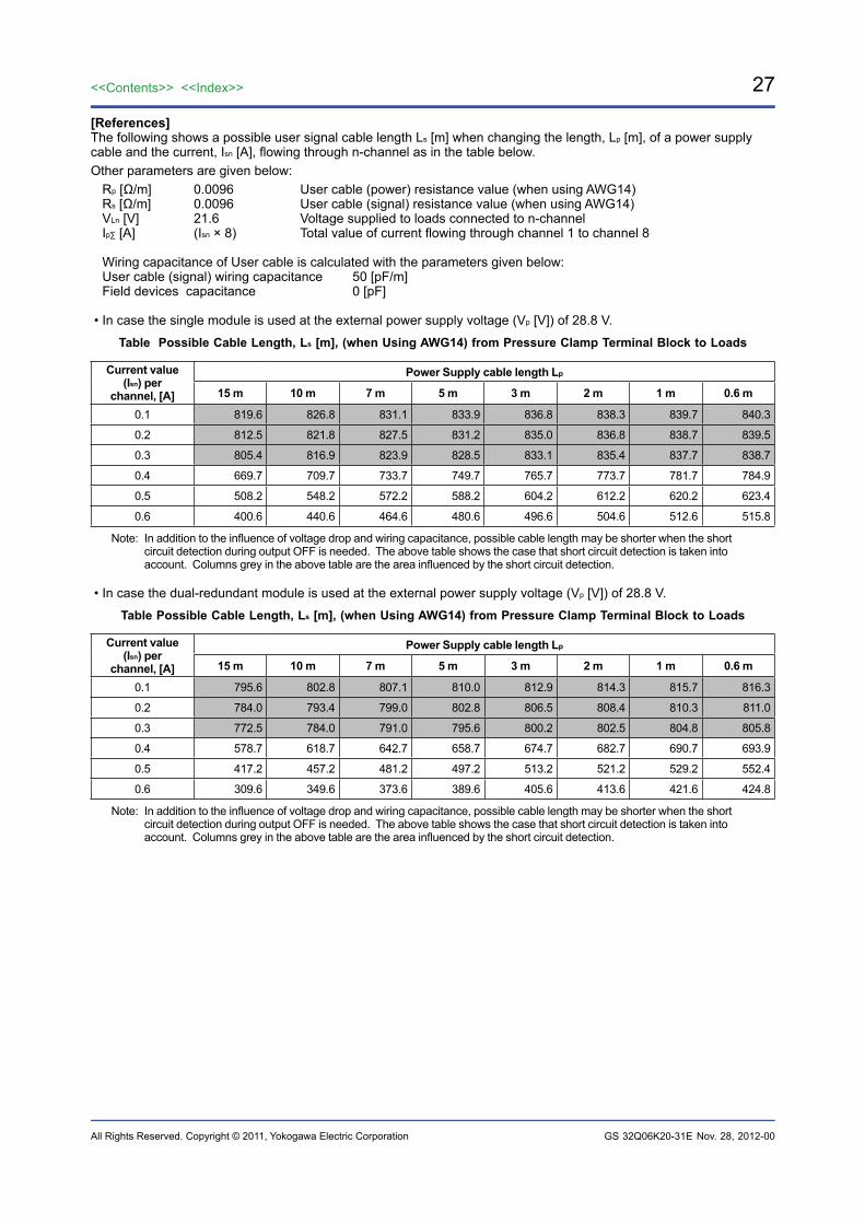
[References]The following shows a possible user signal cable length Ls [m] when changing the length, Lp [m], of a power supply cable and the current, Isn [A], flowing through n-channel as in the table below.Other parameters are given below:
Rp [Ω/m] 0.0096 User cable (power) resistance value (when using AWG14)Rs [Ω/m] 0.0096 User cable (signal) resistance value (when using AWG14)VLn [V] 21.6 Voltage supplied to loads connected to n-channelIp∑ [A] (Isn × 8) Total value of current flowing through channel 1 to channel 8
Wiring capacitance of User cable is calculated with the parameters given below:User cable (signal) wiring capacitance 50 [pF/m]Field devices capacitance 0 [pF]
• In case the single module is used at the external power supply voltage (Vp [V]) of 28.8 V.
Table Possible Cable Length, Ls [m], (when Using AWG14) from Pressure Clamp Terminal Block to Loads
Current value (Isn) per
channel, [A]
Power Supply cable length Lp 15 m 10 m 7 m 5 m 3 m 2 m 1 m 0.6 m
0.1 819.6 826.8 831.1 833.9 836.8 838.3 839.7 840.3
0.2 812.5 821.8 827.5 831.2 835.0 836.8 838.7 839.5
0.3 805.4 816.9 823.9 828.5 833.1 835.4 837.7 838.7
0.4 669.7 709.7 733.7 749.7 765.7 773.7 781.7 784.9
0.5 508.2 548.2 572.2 588.2 604.2 612.2 620.2 623.4
0.6 400.6 440.6 464.6 480.6 496.6 504.6 512.6 515.8
Note: In addition to the influence of voltage drop and wiring capacitance, possible cable length may be shorter when the short circuit detection during output OFF is needed. The above table shows the case that short circuit detection is taken into account. Columns grey in the above table are the area influenced by the short circuit detection.
• In case the dual-redundant module is used at the external power supply voltage (Vp [V]) of 28.8 V.
Table Possible Cable Length, Ls [m], (when Using AWG14) from Pressure Clamp Terminal Block to Loads
Current value (Isn) per
channel, [A]
Power Supply cable length Lp 15 m 10 m 7 m 5 m 3 m 2 m 1 m 0.6 m
0.1 795.6 802.8 807.1 810.0 812.9 814.3 815.7 816.3
0.2 784.0 793.4 799.0 802.8 806.5 808.4 810.3 811.0
0.3 772.5 784.0 791.0 795.6 800.2 802.5 804.8 805.8
0.4 578.7 618.7 642.7 658.7 674.7 682.7 690.7 693.9
0.5 417.2 457.2 481.2 497.2 513.2 521.2 529.2 552.4
0.6 309.6 349.6 373.6 389.6 405.6 413.6 421.6 424.8
Note: In addition to the influence of voltage drop and wiring capacitance, possible cable length may be shorter when the short circuit detection during output OFF is needed. The above table shows the case that short circuit detection is taken into account. Columns grey in the above table are the area influenced by the short circuit detection.
Nov. 28, 2012-00
28
All Rights Reserved. Copyright © 2011, Yokogawa Electric Corporation
<<Contents>> <<Index>>
GS 32Q06K20-31E
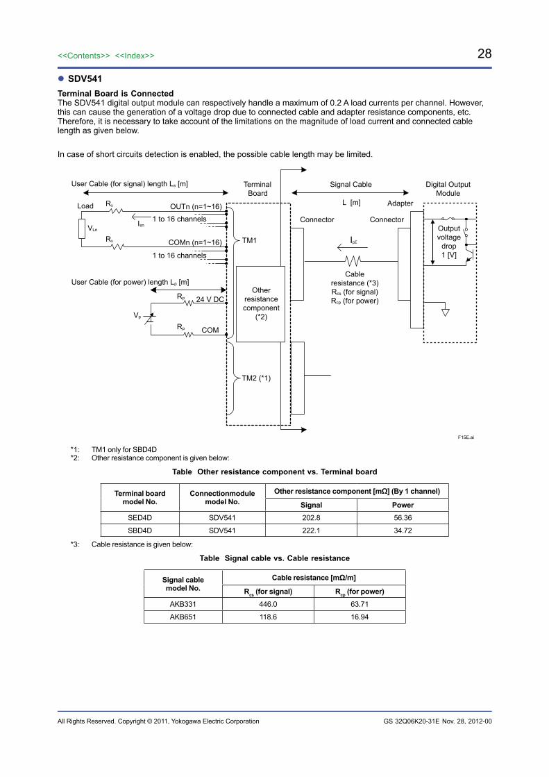
SDV541Terminal Board is ConnectedThe SDV541 digital output module can respectively handle a maximum of 0.2 A load currents per channel. However, this can cause the generation of a voltage drop due to connected cable and adapter resistance components, etc. Therefore, it is necessary to take account of the limitations on the magnitude of load current and connected cable length as given below.
In case of short circuits detection is enabled, the possible cable length may be limited.
F15E.ai
Digital OutputModule
TerminalBoard
Signal Cable
Adapter
Connector
TM1
TM2 (*1)
24 V DC
COM
User Cable (for power) length Lp [m]
Rp
Rp
Vp
Load OUTn (n=1~16)
COMn (n=1~16)
VLn
RS
RS
User Cable (for signal) length Ls [m]
1 to 16 channelsIsn
Otherresistancecomponent
(*2)
Ip∑
Connector
L [m]
1 to 16 channels
Cableresistance (*3)Rcs (for signal)Rcp (for power)
Outputvoltage
drop1 [V]
*1: TM1 only for SBD4D*2: Other resistance component is given below:
Table Other resistance component vs. Terminal board
Terminal board model No.
Connectionmodule model No.
Other resistance component [mΩ] (By 1 channel)
Signal PowerSED4D SDV541 202.8 56.36
SBD4D SDV541 222.1 34.72
*3: Cable resistance is given below:
Table Signal cable vs. Cable resistance
Signal cablemodel No.
Cable resistance [mΩ/m]
Rcs (for signal) Rcp (for power)AKB331 446.0 63.71
AKB651 118.6 16.94
Nov. 28, 2012-00
29<<Contents>> <<Index>>
All Rights Reserved. Copyright © 2011, Yokogawa Electric Corporation GS 32Q06K20-31E
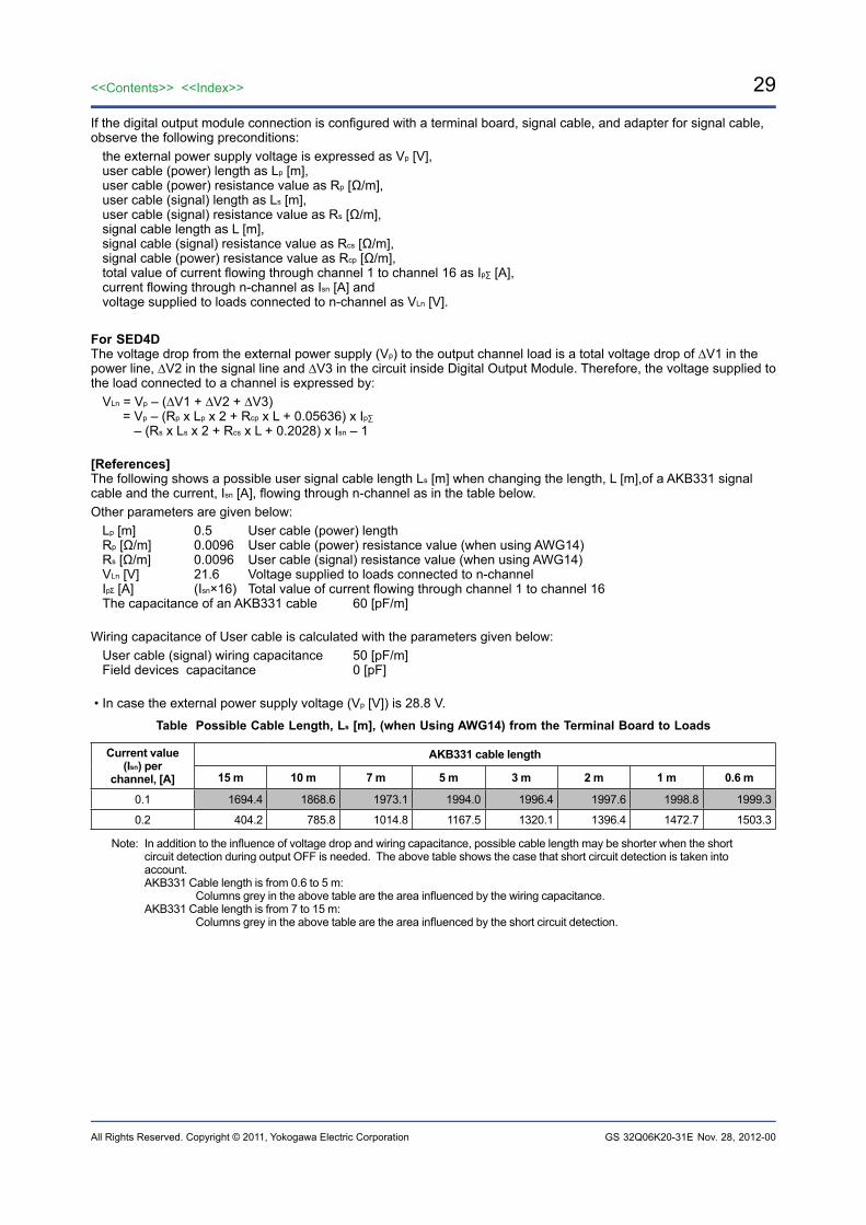
If the digital output module connection is configured with a terminal board, signal cable, and adapter for signal cable, observe the following preconditions:
the external power supply voltage is expressed as Vp [V],user cable (power) length as Lp [m],user cable (power) resistance value as Rp [Ω/m],user cable (signal) length as Ls [m],user cable (signal) resistance value as Rs [Ω/m],signal cable length as L [m],signal cable (signal) resistance value as Rcs [Ω/m],signal cable (power) resistance value as Rcp [Ω/m],total value of current flowing through channel 1 to channel 16 as Ip∑ [A],current flowing through n-channel as Isn [A] andvoltage supplied to loads connected to n-channel as VLn [V].
For SED4DThe voltage drop from the external power supply (Vp) to the output channel load is a total voltage drop of ∆V1 in the power line, ∆V2 in the signal line and ∆V3 in the circuit inside Digital Output Module. Therefore, the voltage supplied to the load connected to a channel is expressed by:
VLn = Vp – (∆V1 + ∆V2 + ∆V3) = Vp – (Rp x Lp x 2 + Rcp x L + 0.05636) x Ip∑
– (Rs x Ls x 2 + Rcs x L + 0.2028) x Isn – 1
[References]The following shows a possible user signal cable length Ls [m] when changing the length, L [m],of a AKB331 signal cable and the current, Isn [A], flowing through n-channel as in the table below.Other parameters are given below:
Lp [m] 0.5 User cable (power) lengthRp [Ω/m] 0.0096 User cable (power) resistance value (when using AWG14)Rs [Ω/m] 0.0096 User cable (signal) resistance value (when using AWG14)VLn [V] 21.6 Voltage supplied to loads connected to n-channelIp [A] (Isn×16) Total value of current flowing through channel 1 to channel 16The capacitance of an AKB331 cable 60 [pF/m]
Wiring capacitance of User cable is calculated with the parameters given below:User cable (signal) wiring capacitance 50 [pF/m]Field devices capacitance 0 [pF]
• In case the external power supply voltage (Vp [V]) is 28.8 V.
Table Possible Cable Length, Ls [m], (when Using AWG14) from the Terminal Board to Loads
Current value (Isn) per
channel, [A]
AKB331 cable length
15 m 10 m 7 m 5 m 3 m 2 m 1 m 0.6 m
0.1 1694.4 1868.6 1973.1 1994.0 1996.4 1997.6 1998.8 1999.3
0.2 404.2 785.8 1014.8 1167.5 1320.1 1396.4 1472.7 1503.3
Note: In addition to the influence of voltage drop and wiring capacitance, possible cable length may be shorter when the short circuit detection during output OFF is needed. The above table shows the case that short circuit detection is taken into account.
AKB331 Cable length is from 0.6 to 5 m: Columns grey in the above table are the area influenced by the wiring capacitance.
AKB331 Cable length is from 7 to 15 m: Columns grey in the above table are the area influenced by the short circuit detection.
Nov. 28, 2012-00
30
All Rights Reserved. Copyright © 2011, Yokogawa Electric Corporation
<<Contents>> <<Index>>
GS 32Q06K20-31E
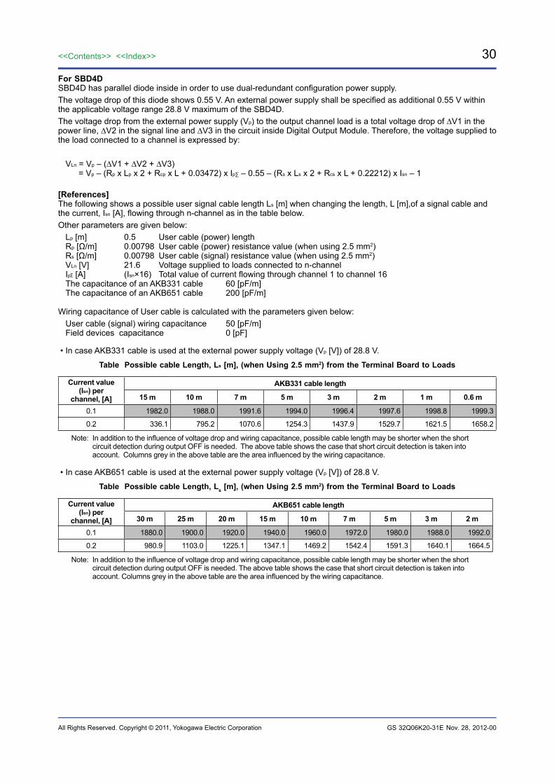
For SBD4DSBD4D has parallel diode inside in order to use dual-redundant configuration power supply.The voltage drop of this diode shows 0.55 V. An external power supply shall be specified as additional 0.55 V within the applicable voltage range 28.8 V maximum of the SBD4D.The voltage drop from the external power supply (Vp) to the output channel load is a total voltage drop of ∆V1 in the power line, ∆V2 in the signal line and ∆V3 in the circuit inside Digital Output Module. Therefore, the voltage supplied to the load connected to a channel is expressed by:
VLn = Vp – (∆V1 + ∆V2 + ∆V3) = Vp – (Rp x Lp x 2 + Rcp x L + 0.03472) x Ip∑ – 0.55 – (Rs x Ls x 2 + Rcs x L + 0.22212) x Isn – 1
[References]The following shows a possible user signal cable length Ls [m] when changing the length, L [m],of a signal cable and the current, Isn [A], flowing through n-channel as in the table below.Other parameters are given below:
Lp [m] 0.5 User cable (power) lengthRp [Ω/m] 0.00798 User cable (power) resistance value (when using 2.5 mm2)Rs [Ω/m] 0.00798 User cable (signal) resistance value (when using 2.5 mm2)VLn [V] 21.6 Voltage supplied to loads connected to n-channelIp [A] (Isn×16) Total value of current flowing through channel 1 to channel 16The capacitance of an AKB331 cable 60 [pF/m]The capacitance of an AKB651 cable 200 [pF/m]
Wiring capacitance of User cable is calculated with the parameters given below:User cable (signal) wiring capacitance 50 [pF/m]Field devices capacitance 0 [pF]
• In case AKB331 cable is used at the external power supply voltage (Vp [V]) of 28.8 V.
Table Possible cable Length, Ls [m], (when Using 2.5 mm2) from the Terminal Board to Loads
Current value (Isn) per
channel, [A]
AKB331 cable length
15 m 10 m 7 m 5 m 3 m 2 m 1 m 0.6 m
0.1 1982.0 1988.0 1991.6 1994.0 1996.4 1997.6 1998.8 1999.3
0.2 336.1 795.2 1070.6 1254.3 1437.9 1529.7 1621.5 1658.2
Note: In addition to the influence of voltage drop and wiring capacitance, possible cable length may be shorter when the short circuit detection during output OFF is needed. The above table shows the case that short circuit detection is taken into account. Columns grey in the above table are the area influenced by the wiring capacitance.
• In case AKB651 cable is used at the external power supply voltage (Vp [V]) of 28.8 V.
Table Possible cable Length, Ls [m], (when Using 2.5 mm2) from the Terminal Board to Loads
Current value (Isn) per
channel, [A]
AKB651 cable length
30 m 25 m 20 m 15 m 10 m 7 m 5 m 3 m 2 m
0.1 1880.0 1900.0 1920.0 1940.0 1960.0 1972.0 1980.0 1988.0 1992.0
0.2 980.9 1103.0 1225.1 1347.1 1469.2 1542.4 1591.3 1640.1 1664.5
Note: In addition to the influence of voltage drop and wiring capacitance, possible cable length may be shorter when the short circuit detection during output OFF is needed. The above table shows the case that short circuit detection is taken into account. Columns grey in the above table are the area influenced by the wiring capacitance.
Nov. 28, 2012-00

31<<Contents>> <<Index>>
All Rights Reserved. Copyright © 2011, Yokogawa Electric Corporation GS 32Q06K20-31E
MIL Connector is Connected
F16E.ai
24 V DC
COM
User Cable (for power) length
Load OUTn (n=1~16)
COMn (n=1~16)
VLn
User Cable (for signal) length
Rs
Rs
Isn
Ls [m]
Lp [m]
Rp
Rp
Vp
Digital OutputModuleMIL Connector
Otherresistancecomponent
Signal20.0 [mΩ]
Power2.86 [mΩ]
1 to 16 channels
1 to 16 channels
Outputvoltage
drop1 [V]
Where a MIL connector is used, assuming that:the external power supply voltage is expressed as Vp [V], user cable (power) length as Lp [m], user cable (power) resistance value as Rp [Ω/m], user cable (signal) length as Ls [m], user cable (signal) resistance value Rs [Ω/m], total value of current flowing through channel 1 to channel 16 as Ip∑, current flowing through n-channel as Isn [A], and voltage supplied to loads connected to n-channel as VLn [V].
The voltage drop from the external power supply (Vp) to the output channel load is a total voltage drop of ∆V1 in the power line, ∆V2 in the signal line and ∆V3 in the circuit inside Digital Output Module. Therefore, the voltage supplied to the load connected to a channel is expressed by:
VLn = Vp – (∆V1 + ∆V2 + ∆V3) = Vp – (Rp × Lp ÷ 7 × 0.00286) × I p∑ – (Rs × Ls × 2 + 0.0200) × Isn – 1
Nov. 28, 2012-00
32
All Rights Reserved. Copyright © 2011, Yokogawa Electric Corporation
<<Contents>> <<Index>>
GS 32Q06K20-31E
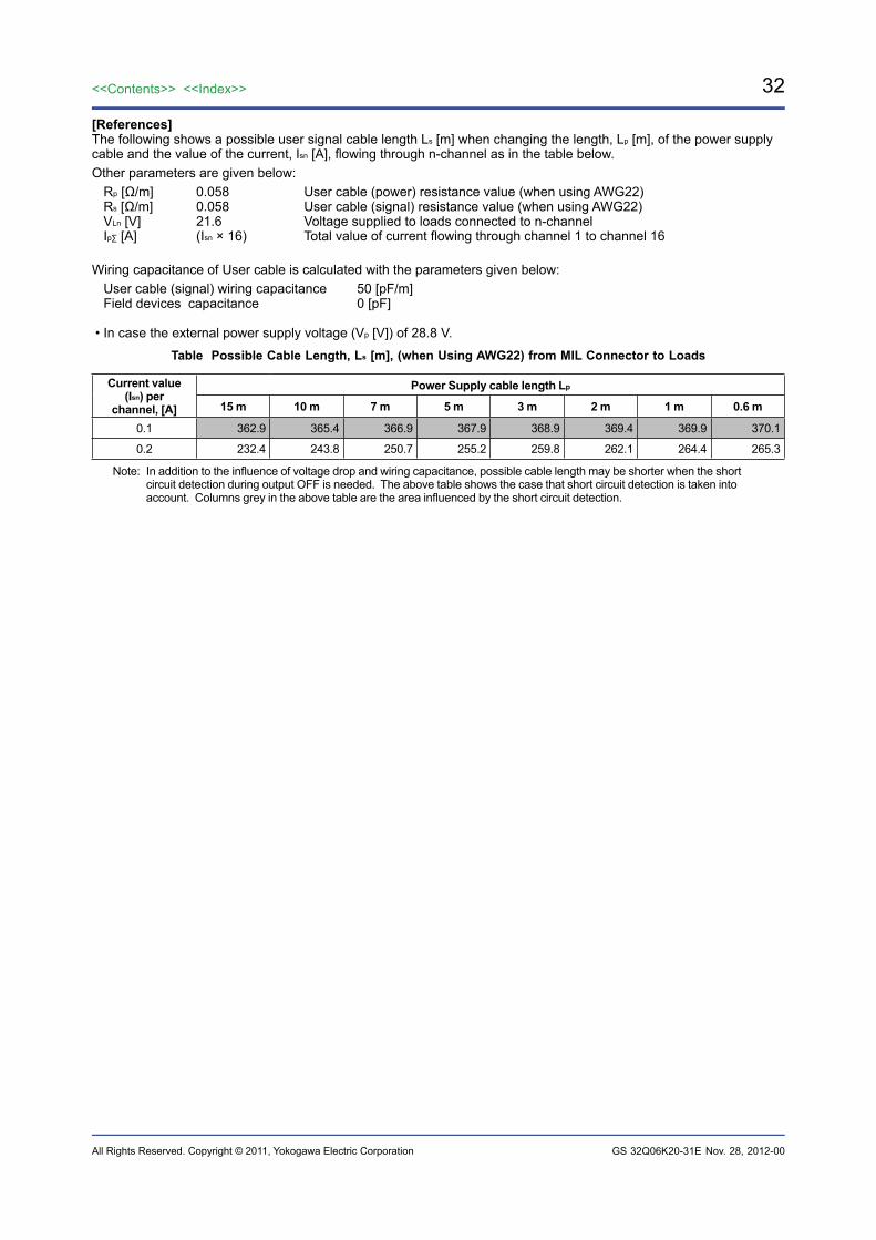
[References]The following shows a possible user signal cable length Ls [m] when changing the length, Lp [m], of the power supply cable and the value of the current, Isn [A], flowing through n-channel as in the table below.Other parameters are given below:
Rp [Ω/m] 0.058 User cable (power) resistance value (when using AWG22)Rs [Ω/m] 0.058 User cable (signal) resistance value (when using AWG22)VLn [V] 21.6 Voltage supplied to loads connected to n-channelIp∑ [A] (Isn × 16) Total value of current flowing through channel 1 to channel 16
Wiring capacitance of User cable is calculated with the parameters given below:User cable (signal) wiring capacitance 50 [pF/m]Field devices capacitance 0 [pF]
• In case the external power supply voltage (Vp [V]) of 28.8 V.
Table Possible Cable Length, Ls [m], (when Using AWG22) from MIL Connector to Loads
Current value (Isn) per
channel, [A]
Power Supply cable length Lp
15 m 10 m 7 m 5 m 3 m 2 m 1 m 0.6 m
0.1 362.9 365.4 366.9 367.9 368.9 369.4 369.9 370.1
0.2 232.4 243.8 250.7 255.2 259.8 262.1 264.4 265.3
Note: In addition to the influence of voltage drop and wiring capacitance, possible cable length may be shorter when the short circuit detection during output OFF is needed. The above table shows the case that short circuit detection is taken into account. Columns grey in the above table are the area influenced by the short circuit detection.
Nov. 28, 2012-00
33<<Contents>> <<Index>>
All Rights Reserved. Copyright © 2011, Yokogawa Electric Corporation GS 32Q06K20-31E
Pressure Clamp Terminal Block is Connected
F17E.ai
Other resistance component
Signal 145.6[mΩ]
Power 24.06[mΩ]
Other resistance component
Signal 323.4[mΩ]
Power 220.26[mΩ]
24 V DC
COM
User Cable (for power) length
Rp
Rp
Load
VLn
User Cable (for signal) length
Rs
Rs
Isn
Vp
Ls [m]
Lp [m]
Single module Dual-redundant module
Digital Output Module
Digital Output Module
Pressure Clamp
Terminal block
Pressure Clamp
Terminal block
24 V DC
COM
1 to 16 channels
1 to 16 channels
OUTn (n=1~16) OUTn (n=1~16)
COMn (n=1~16) COMn (n=1~16)
1 to 16 channels
1 to 16 channels
Outputvoltage
drop1 [V]
Outputvoltage
drop1 [V]
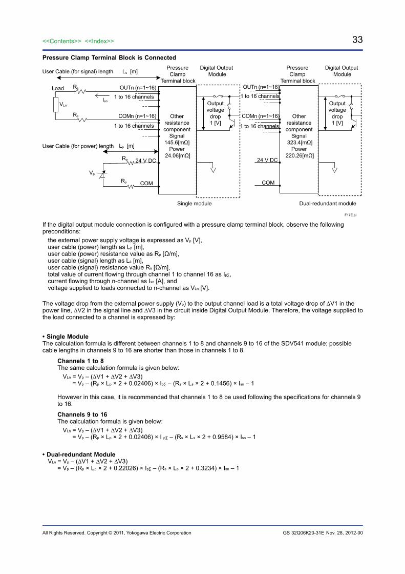
If the digital output module connection is configured with a pressure clamp terminal block, observe the following preconditions:
the external power supply voltage is expressed as Vp [V], user cable (power) length as Lp [m], user cable (power) resistance value as Rp [Ω/m], user cable (signal) length as Ls [m], user cable (signal) resistance value Rs [Ω/m], total value of current flowing through channel 1 to channel 16 as Ip∑, current flowing through n-channel as Isn [A], and voltage supplied to loads connected to n-channel as VLn [V].
The voltage drop from the external power supply (Vp) to the output channel load is a total voltage drop of ∆V1 in the power line, ∆V2 in the signal line and ∆V3 in the circuit inside Digital Output Module. Therefore, the voltage supplied to the load connected to a channel is expressed by:
• Single ModuleThe calculation formula is different between channels 1 to 8 and channels 9 to 16 of the SDV541 module; possible cable lengths in channels 9 to 16 are shorter than those in channels 1 to 8.
Channels 1 to 8 The same calculation formula is given below:
VLn = Vp – (∆V1 + ∆V2 + ∆V3) = Vp – (Rp × Lp × 2 + 0.02406) × Ip∑ – (Rs × Ls × 2 + 0.1456) × Isn – 1
However in this case, it is recommended that channels 1 to 8 be used following the specifications for channels 9 to 16.
Channels 9 to 16 The calculation formula is given below:
VLn = Vp – (∆V1 + ∆V2 + ∆V3) = Vp – (Rp × Lp × 2 + 0.02406) × I p∑ – (Rs × Ls × 2 + 0.9584) × Isn – 1
• Dual-redundant ModuleVLn = Vp – (∆V1 + ∆V2 + ∆V3) = Vp – (Rp × Lp × 2 + 0.22026) × Ip∑ – (Rs × Ls × 2 + 0.3234) × Isn – 1
Nov. 28, 2012-00
34
All Rights Reserved. Copyright © 2011, Yokogawa Electric Corporation
<<Contents>> <<Index>>
GS 32Q06K20-31E
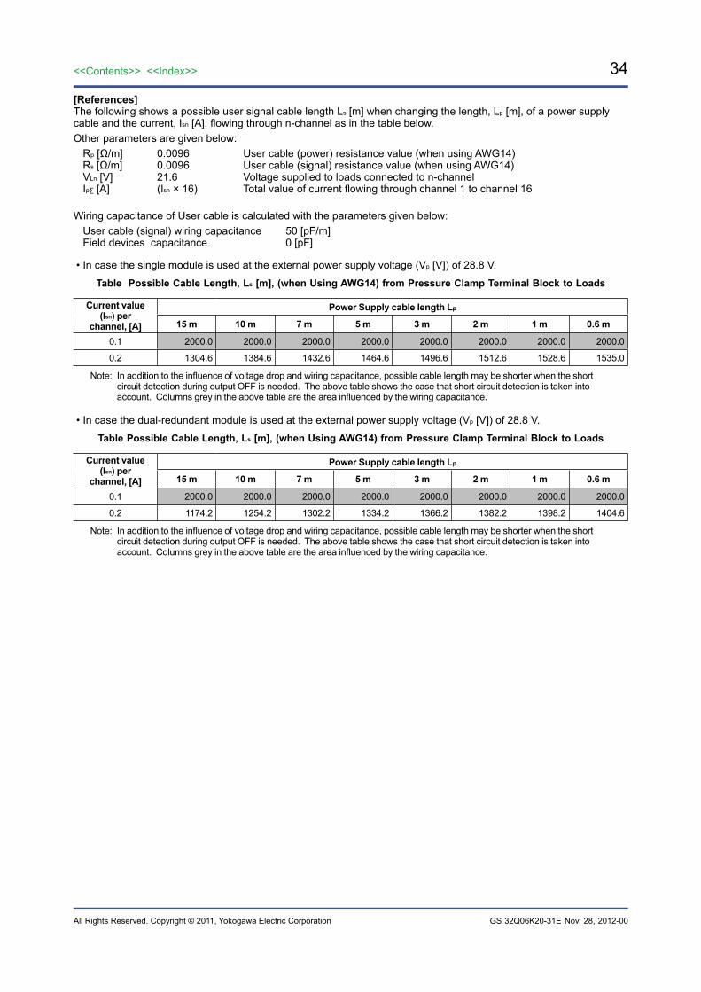
[References]The following shows a possible user signal cable length Ls [m] when changing the length, Lp [m], of a power supply cable and the current, Isn [A], flowing through n-channel as in the table below.Other parameters are given below:
Rp [Ω/m] 0.0096 User cable (power) resistance value (when using AWG14)Rs [Ω/m] 0.0096 User cable (signal) resistance value (when using AWG14)VLn [V] 21.6 Voltage supplied to loads connected to n-channelIp∑ [A] (Isn × 16) Total value of current flowing through channel 1 to channel 16
Wiring capacitance of User cable is calculated with the parameters given below:User cable (signal) wiring capacitance 50 [pF/m]Field devices capacitance 0 [pF]
• In case the single module is used at the external power supply voltage (Vp [V]) of 28.8 V.
Table Possible Cable Length, Ls [m], (when Using AWG14) from Pressure Clamp Terminal Block to Loads
Current value (Isn) per
channel, [A]
Power Supply cable length Lp
15 m 10 m 7 m 5 m 3 m 2 m 1 m 0.6 m
0.1 2000.0 2000.0 2000.0 2000.0 2000.0 2000.0 2000.0 2000.0
0.2 1304.6 1384.6 1432.6 1464.6 1496.6 1512.6 1528.6 1535.0
Note: In addition to the influence of voltage drop and wiring capacitance, possible cable length may be shorter when the short circuit detection during output OFF is needed. The above table shows the case that short circuit detection is taken into account. Columns grey in the above table are the area influenced by the wiring capacitance.
• In case the dual-redundant module is used at the external power supply voltage (Vp [V]) of 28.8 V.
Table Possible Cable Length, Ls [m], (when Using AWG14) from Pressure Clamp Terminal Block to Loads
Current value (Isn) per
channel, [A]
Power Supply cable length Lp
15 m 10 m 7 m 5 m 3 m 2 m 1 m 0.6 m
0.1 2000.0 2000.0 2000.0 2000.0 2000.0 2000.0 2000.0 2000.0
0.2 1174.2 1254.2 1302.2 1334.2 1366.2 1382.2 1398.2 1404.6
Note: In addition to the influence of voltage drop and wiring capacitance, possible cable length may be shorter when the short circuit detection during output OFF is needed. The above table shows the case that short circuit detection is taken into account. Columns grey in the above table are the area influenced by the wiring capacitance.
Nov. 28, 2012-00
35<<Contents>> <<Index>>
All Rights Reserved. Copyright © 2011, Yokogawa Electric Corporation GS 32Q06K20-31E
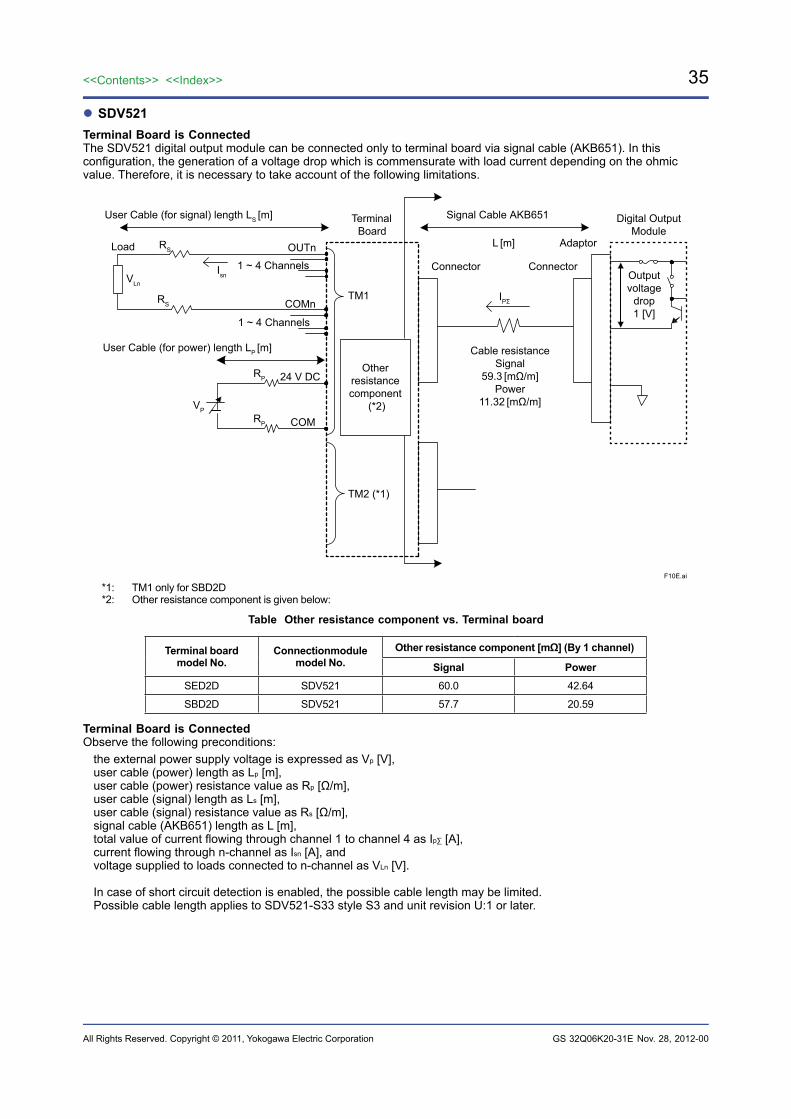
SDV521Terminal Board is ConnectedThe SDV521 digital output module can be connected only to terminal board via signal cable (AKB651). In this configuration, the generation of a voltage drop which is commensurate with load current depending on the ohmic value. Therefore, it is necessary to take account of the following limitations.
F10E.ai
TerminalBoard
Digital OutputModule
Signal Cable AKB651
Adaptor
Connector Connector
L [m]
TM1
TM2 (*1)
24 V DC
COM
Load OUTn
COMn
VLn
1 ~ 4 Channels
RS
RS
Isn
IPΣ
Otherresistancecomponent
(*2)
Cable resistanceSignal
59.3 [mΩ/m]Power
11.32 [mΩ/m]
RP
RP
VP
User Cable (for power) length LP [m]
User Cable (for signal) length LS [m]
1 ~ 4 Channels
Outputvoltage
drop1 [V]
*1: TM1 only for SBD2D*2: Other resistance component is given below:
Table Other resistance component vs. Terminal board
Terminal board model No.
Connectionmodule model No.
Other resistance component [mΩ] (By 1 channel)
Signal PowerSED2D SDV521 60.0 42.64
SBD2D SDV521 57.7 20.59
Terminal Board is ConnectedObserve the following preconditions:
the external power supply voltage is expressed as Vp [V],user cable (power) length as Lp [m],user cable (power) resistance value as Rp [Ω/m],user cable (signal) length as Ls [m],user cable (signal) resistance value as Rs [Ω/m],signal cable (AKB651) length as L [m],total value of current flowing through channel 1 to channel 4 as Ip∑ [A],current flowing through n-channel as Isn [A], andvoltage supplied to loads connected to n-channel as VLn [V].
In case of short circuit detection is enabled, the possible cable length may be limited.Possible cable length applies to SDV521-S33 style S3 and unit revision U:1 or later.
Nov. 28, 2012-00
36
All Rights Reserved. Copyright © 2011, Yokogawa Electric Corporation
<<Contents>> <<Index>>
GS 32Q06K20-31E
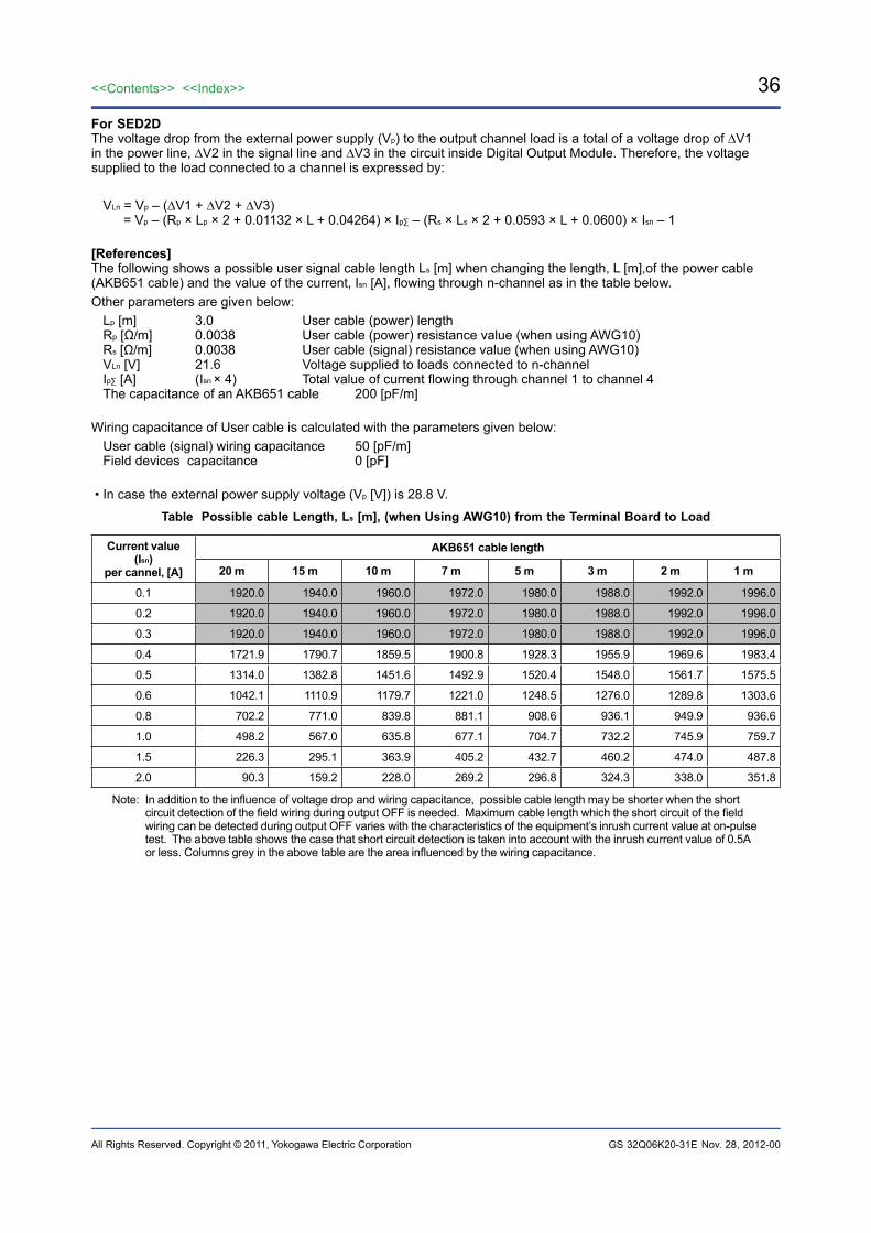
For SED2DThe voltage drop from the external power supply (Vp) to the output channel load is a total of a voltage drop of ∆V1 in the power line, ∆V2 in the signal line and ∆V3 in the circuit inside Digital Output Module. Therefore, the voltage supplied to the load connected to a channel is expressed by:
VLn = Vp – (∆V1 + ∆V2 + ∆V3) = Vp – (Rp × Lp × 2 + 0.01132 × L + 0.04264) × Ip∑ – (Rs × Ls × 2 + 0.0593 × L + 0.0600) × Isn – 1
[References]The following shows a possible user signal cable length Ls [m] when changing the length, L [m],of the power cable (AKB651 cable) and the value of the current, Isn [A], flowing through n-channel as in the table below.Other parameters are given below:
Lp [m] 3.0 User cable (power) lengthRp [Ω/m] 0.0038 User cable (power) resistance value (when using AWG10)Rs [Ω/m] 0.0038 User cable (signal) resistance value (when using AWG10)VLn [V] 21.6 Voltage supplied to loads connected to n-channelIp∑ [A] (Isn × 4) Total value of current flowing through channel 1 to channel 4The capacitance of an AKB651 cable 200 [pF/m]
Wiring capacitance of User cable is calculated with the parameters given below:User cable (signal) wiring capacitance 50 [pF/m]Field devices capacitance 0 [pF]
• In case the external power supply voltage (Vp [V]) is 28.8 V.
Table Possible cable Length, Ls [m], (when Using AWG10) from the Terminal Board to Load
Current value (Isn)
per cannel, [A]
AKB651 cable length
20 m 15 m 10 m 7 m 5 m 3 m 2 m 1 m
0.1 1920.0 1940.0 1960.0 1972.0 1980.0 1988.0 1992.0 1996.0
0.2 1920.0 1940.0 1960.0 1972.0 1980.0 1988.0 1992.0 1996.0
0.3 1920.0 1940.0 1960.0 1972.0 1980.0 1988.0 1992.0 1996.0
0.4 1721.9 1790.7 1859.5 1900.8 1928.3 1955.9 1969.6 1983.4
0.5 1314.0 1382.8 1451.6 1492.9 1520.4 1548.0 1561.7 1575.5
0.6 1042.1 1110.9 1179.7 1221.0 1248.5 1276.0 1289.8 1303.6
0.8 702.2 771.0 839.8 881.1 908.6 936.1 949.9 936.6
1.0 498.2 567.0 635.8 677.1 704.7 732.2 745.9 759.7
1.5 226.3 295.1 363.9 405.2 432.7 460.2 474.0 487.8
2.0 90.3 159.2 228.0 269.2 296.8 324.3 338.0 351.8
Note: In addition to the influence of voltage drop and wiring capacitance, possible cable length may be shorter when the short circuit detection of the field wiring during output OFF is needed. Maximum cable length which the short circuit of the field wiring can be detected during output OFF varies with the characteristics of the equipment’s inrush current value at on-pulse test. The above table shows the case that short circuit detection is taken into account with the inrush current value of 0.5A or less. Columns grey in the above table are the area influenced by the wiring capacitance.
Nov. 28, 2012-00
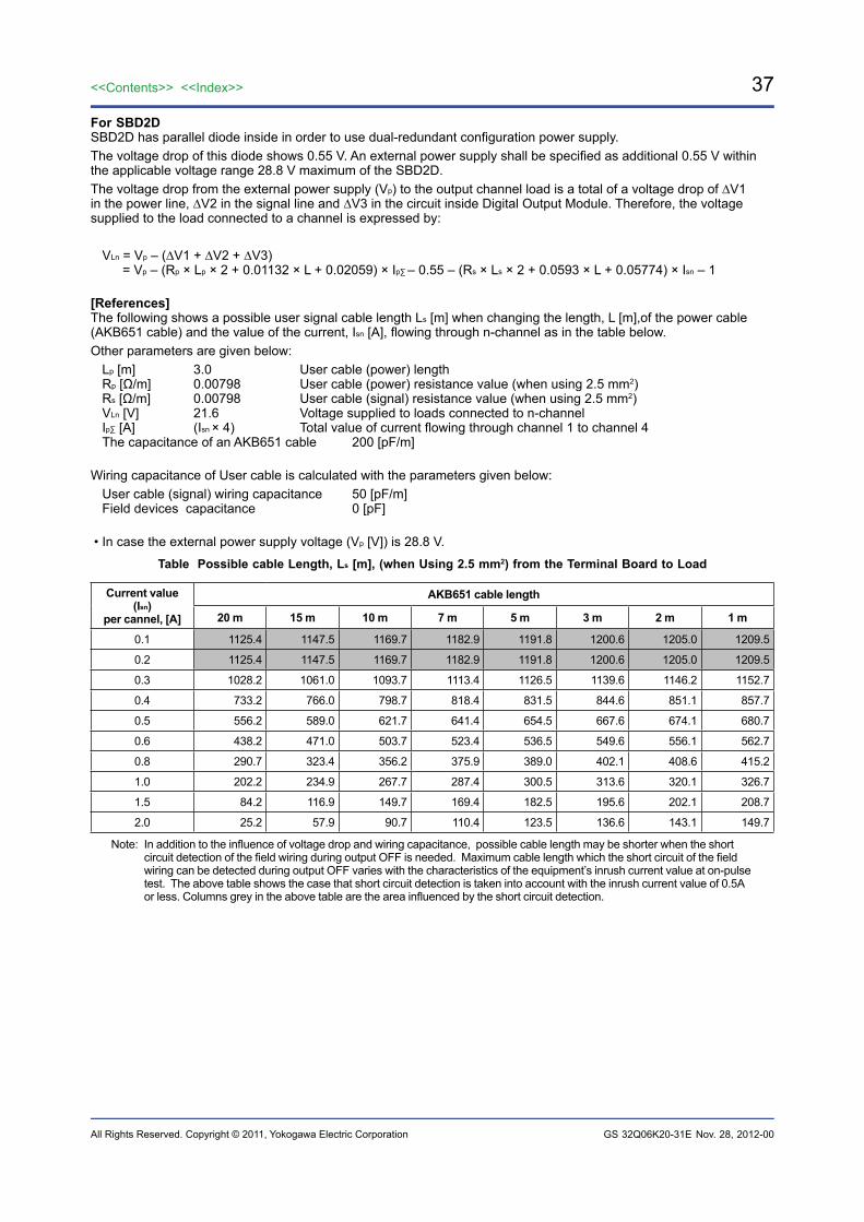
37<<Contents>> <<Index>>
All Rights Reserved. Copyright © 2011, Yokogawa Electric Corporation GS 32Q06K20-31E
For SBD2DSBD2D has parallel diode inside in order to use dual-redundant configuration power supply.The voltage drop of this diode shows 0.55 V. An external power supply shall be specified as additional 0.55 V within the applicable voltage range 28.8 V maximum of the SBD2D.The voltage drop from the external power supply (Vp) to the output channel load is a total of a voltage drop of ∆V1 in the power line, ∆V2 in the signal line and ∆V3 in the circuit inside Digital Output Module. Therefore, the voltage supplied to the load connected to a channel is expressed by:
VLn = Vp – (∆V1 + ∆V2 + ∆V3) = Vp – (Rp × Lp × 2 + 0.01132 × L + 0.02059) × Ip∑ – 0.55 – (Rs × Ls × 2 + 0.0593 × L + 0.05774) × Isn – 1
[References]The following shows a possible user signal cable length Ls [m] when changing the length, L [m],of the power cable (AKB651 cable) and the value of the current, Isn [A], flowing through n-channel as in the table below.Other parameters are given below:
Lp [m] 3.0 User cable (power) lengthRp [Ω/m] 0.00798 User cable (power) resistance value (when using 2.5 mm2)Rs [Ω/m] 0.00798 User cable (signal) resistance value (when using 2.5 mm2)VLn [V] 21.6 Voltage supplied to loads connected to n-channelIp∑ [A] (Isn × 4) Total value of current flowing through channel 1 to channel 4The capacitance of an AKB651 cable 200 [pF/m]
Wiring capacitance of User cable is calculated with the parameters given below:User cable (signal) wiring capacitance 50 [pF/m]Field devices capacitance 0 [pF]
• In case the external power supply voltage (Vp [V]) is 28.8 V.
Table Possible cable Length, Ls [m], (when Using 2.5 mm2) from the Terminal Board to Load
Current value (Isn)
per cannel, [A]
AKB651 cable length
20 m 15 m 10 m 7 m 5 m 3 m 2 m 1 m
0.1 1125.4 1147.5 1169.7 1182.9 1191.8 1200.6 1205.0 1209.5
0.2 1125.4 1147.5 1169.7 1182.9 1191.8 1200.6 1205.0 1209.5
0.3 1028.2 1061.0 1093.7 1113.4 1126.5 1139.6 1146.2 1152.7
0.4 733.2 766.0 798.7 818.4 831.5 844.6 851.1 857.7
0.5 556.2 589.0 621.7 641.4 654.5 667.6 674.1 680.7
0.6 438.2 471.0 503.7 523.4 536.5 549.6 556.1 562.7
0.8 290.7 323.4 356.2 375.9 389.0 402.1 408.6 415.2
1.0 202.2 234.9 267.7 287.4 300.5 313.6 320.1 326.7
1.5 84.2 116.9 149.7 169.4 182.5 195.6 202.1 208.7
2.0 25.2 57.9 90.7 110.4 123.5 136.6 143.1 149.7
Note: In addition to the influence of voltage drop and wiring capacitance, possible cable length may be shorter when the short circuit detection of the field wiring during output OFF is needed. Maximum cable length which the short circuit of the field wiring can be detected during output OFF varies with the characteristics of the equipment’s inrush current value at on-pulse test. The above table shows the case that short circuit detection is taken into account with the inrush current value of 0.5A or less. Columns grey in the above table are the area influenced by the short circuit detection.
Nov. 28, 2012-00
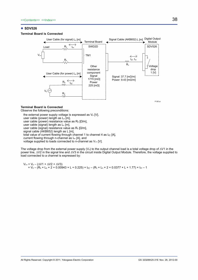
38
All Rights Reserved. Copyright © 2011, Yokogawa Electric Corporation
<<Contents>> <<Index>>
GS 32Q06K20-31E
SDV526Terminal Board is Connected
F12E.ai
User Cable (for power)
SWD2DLoad SDV526
VLn
User Cable (for signal)
Rs
Rs Isn
Ip∑
Ls [m] Signal Cable (AKB652) L [m]
Lp [m]
Rp
Ip∑, Isn
Rp
Rc
Vp
Voltagedrop1 [V]
Digital OutputModuleTerminal Board
Otherresistancecomponent
Signal 1770 [mΩ]
Power 225 [mΩ]
Signal: 37.7 [mΩ/m]Power: 9.43 [mΩ/m]
TM1
Terminal Board is ConnectedObserve the following preconditions:
the external power supply voltage is expressed as Vp [V],user cable (power) length as Lp [m],user cable (power) resistance value as Rp [ /m],user cable (signal) length as Ls [m],user cable (signal) resistance value as Rs [ /m],signal cable (AKB652) length as L [m],total value of current flowing through channel 1 to channel 4 as Ip∑ [A],current flowing through n-channel as Isn [A], andvoltage supplied to loads connected to n-channel as VLn [V].
The voltage drop from the external power supply (Vp) to the output channel load is a total voltage drop of ∆V1 in the power line, ∆V2 in the signal line and ∆V3 in the circuit inside Digital Output Module. Therefore, the voltage supplied to load connected to a channel is expressed by:
VLn = Vp – (∆V1 + ∆V2 + ∆V3) = Vp – (Rp × Lp × 2 + 0.00943 × L + 0.225) × Ip∑ – (Rs × Ls × 2 + 0.0377 × L + 1.77) × Isn – 1
Nov. 28, 2012-00
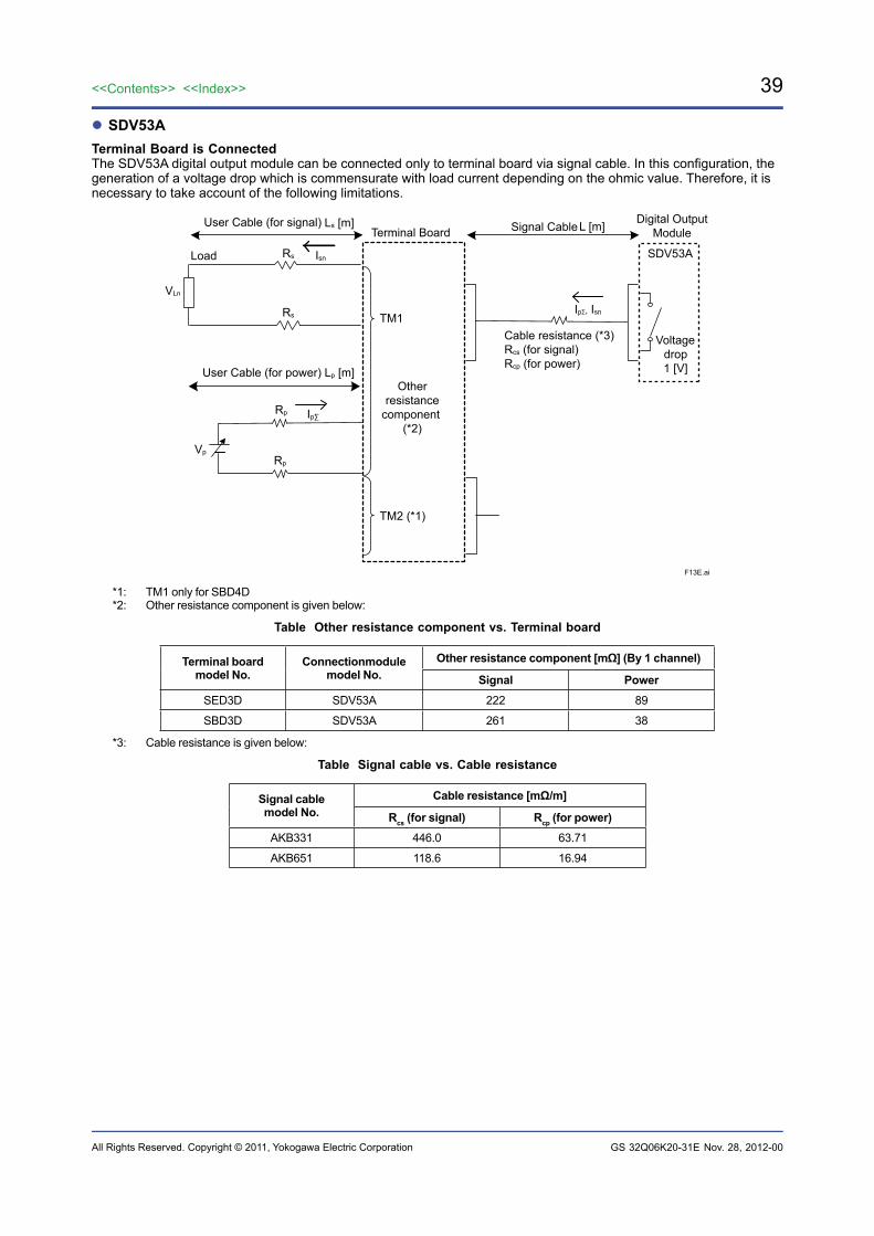
39<<Contents>> <<Index>>
All Rights Reserved. Copyright © 2011, Yokogawa Electric Corporation GS 32Q06K20-31E
SDV53ATerminal Board is ConnectedThe SDV53A digital output module can be connected only to terminal board via signal cable. In this configuration, the generation of a voltage drop which is commensurate with load current depending on the ohmic value. Therefore, it is necessary to take account of the following limitations.
F13E.ai
User Cable (for power)
Load SDV53A
VLn
User Cable (for signal)
Rs
Rs Isn
Ip∑
Ls [m] Signal CableL [m]
Lp [m]
Rp
Ip∑, Isn
Rp
Cable resistance (*3)Rcs (for signal)Rcp (for power)
Vp
Voltagedrop1 [V]
Digital OutputModuleTerminal Board
Otherresistance
component (*2)
TM1
TM2 (*1)
*1: TM1 only for SBD4D*2: Other resistance component is given below:
Table Other resistance component vs. Terminal board
Terminal board model No.
Connectionmodule model No.
Other resistance component [mΩ] (By 1 channel)
Signal PowerSED3D SDV53A 222 89
SBD3D SDV53A 261 38
*3: Cable resistance is given below:
Table Signal cable vs. Cable resistance
Signal cablemodel No.
Cable resistance [mΩ/m]
Rcs (for signal) Rcp (for power)AKB331 446.0 63.71
AKB651 118.6 16.94
Nov. 28, 2012-00
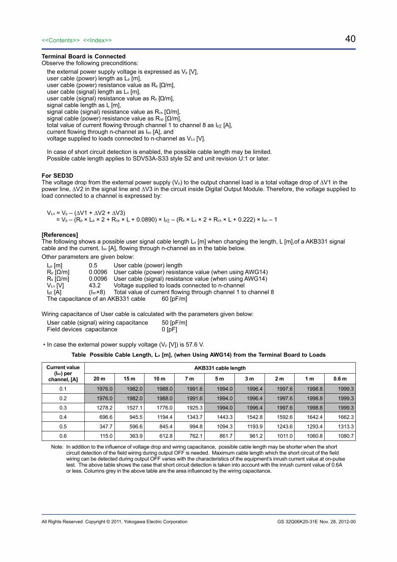
40
All Rights Reserved. Copyright © 2011, Yokogawa Electric Corporation
<<Contents>> <<Index>>
GS 32Q06K20-31E
Terminal Board is ConnectedObserve the following preconditions:
the external power supply voltage is expressed as Vp [V],user cable (power) length as Lp [m],user cable (power) resistance value as Rp [ /m],user cable (signal) length as Ls [m],user cable (signal) resistance value as Rs [ /m],signal cable length as L [m],signal cable (signal) resistance value as Rcs [Ω/m],signal cable (power) resistance value as Rcp [Ω/m],total value of current flowing through channel 1 to channel 8 as Ip∑ [A],current flowing through n-channel as Isn [A], andvoltage supplied to loads connected to n-channel as VLn [V].
In case of short circuit detection is enabled, the possible cable length may be limited.Possible cable length applies to SDV53A-S33 style S2 and unit revision U:1 or later.
For SED3DThe voltage drop from the external power supply (Vp) to the output channel load is a total voltage drop of ∆V1 in the power line, ∆V2 in the signal line and ∆V3 in the circuit inside Digital Output Module. Therefore, the voltage supplied to load connected to a channel is expressed by:
VLn = Vp – (∆V1 + ∆V2 + ∆V3) = Vp – (Rp × Lp × 2 + Rcp × L + 0.0890) × Ip∑ – (Rs × Ls × 2 + Rcs × L + 0.222) × Isn – 1
[References]The following shows a possible user signal cable length Ls [m] when changing the length, L [m],of a AKB331 signal cable and the current, Isn [A], flowing through n-channel as in the table below.Other parameters are given below:
Lp [m] 0.5 User cable (power) lengthRp [Ω/m] 0.0096 User cable (power) resistance value (when using AWG14)Rs [Ω/m] 0.0096 User cable (signal) resistance value (when using AWG14)VLn [V] 43.2 Voltage supplied to loads connected to n-channelIp [A] (Isn×8) Total value of current flowing through channel 1 to channel 8 The capacitance of an AKB331 cable 60 [pF/m]
Wiring capacitance of User cable is calculated with the parameters given below:User cable (signal) wiring capacitance 50 [pF/m]Field devices capacitance 0 [pF]
• In case the external power supply voltage (Vp [V]) is 57.6 V.
Table Possible Cable Length, Ls [m], (when Using AWG14) from the Terminal Board to Loads
Current value (Isn) per
channel, [A]
AKB331 cable length
20 m 15 m 10 m 7 m 5 m 3 m 2 m 1 m 0.6 m
0.1 1976.0 1982.0 1988.0 1991.6 1994.0 1996.4 1997.6 1998.8 1999.3
0.2 1976.0 1982.0 1988.0 1991.6 1994.0 1996.4 1997.6 1998.8 1999.3
0.3 1278.2 1527.1 1776.0 1925.3 1994.0 1996.4 1997.6 1998.8 1999.3
0.4 696.6 945.5 1194.4 1343.7 1443.3 1542.8 1592.6 1642.4 1662.3
0.5 347.7 596.6 845.4 994.8 1094.3 1193.9 1243.6 1293.4 1313.3
0.6 115.0 363.9 612.8 762.1 861.7 961.2 1011.0 1060.8 1080.7
Note: In addition to the influence of voltage drop and wiring capacitance, possible cable length may be shorter when the short circuit detection of the field wiring during output OFF is needed. Maximum cable length which the short circuit of the field wiring can be detected during output OFF varies with the characteristics of the equipment’s inrush current value at on-pulse test. The above table shows the case that short circuit detection is taken into account with the inrush current value of 0.6A or less. Columns grey in the above table are the area influenced by the wiring capacitance.
Nov. 28, 2012-00
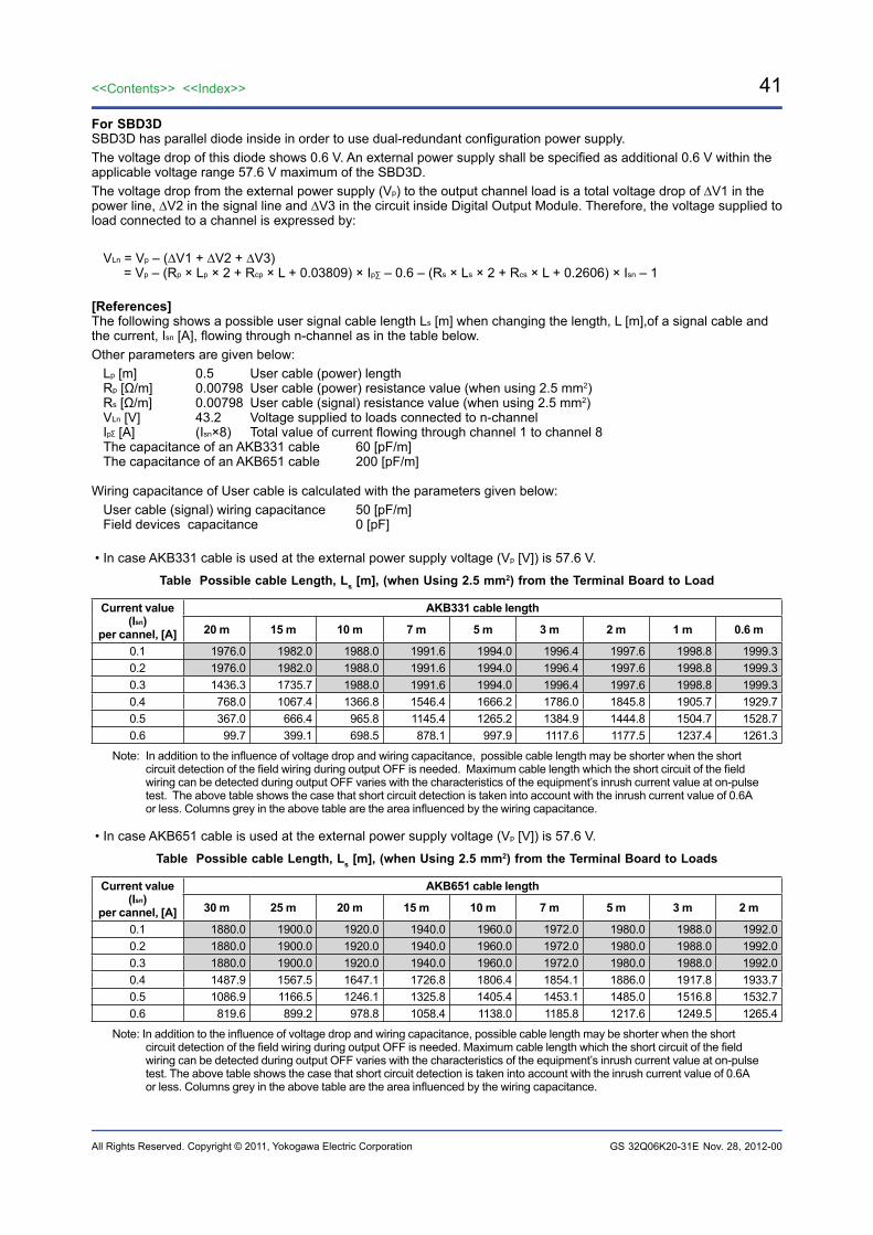
41<<Contents>> <<Index>>
All Rights Reserved. Copyright © 2011, Yokogawa Electric Corporation GS 32Q06K20-31E
For SBD3DSBD3D has parallel diode inside in order to use dual-redundant configuration power supply.The voltage drop of this diode shows 0.6 V. An external power supply shall be specified as additional 0.6 V within the applicable voltage range 57.6 V maximum of the SBD3D.The voltage drop from the external power supply (Vp) to the output channel load is a total voltage drop of ∆V1 in the power line, ∆V2 in the signal line and ∆V3 in the circuit inside Digital Output Module. Therefore, the voltage supplied to load connected to a channel is expressed by:
VLn = Vp – (∆V1 + ∆V2 + ∆V3) = Vp – (Rp × Lp × 2 + Rcp × L + 0.03809) × Ip∑ – 0.6 – (Rs × Ls × 2 + Rcs × L + 0.2606) × Isn – 1
[References]The following shows a possible user signal cable length Ls [m] when changing the length, L [m],of a signal cable and the current, Isn [A], flowing through n-channel as in the table below.Other parameters are given below:
Lp [m] 0.5 User cable (power) lengthRp [Ω/m] 0.00798 User cable (power) resistance value (when using 2.5 mm2)Rs [Ω/m] 0.00798 User cable (signal) resistance value (when using 2.5 mm2)VLn [V] 43.2 Voltage supplied to loads connected to n-channelIp [A] (Isn×8) Total value of current flowing through channel 1 to channel 8 The capacitance of an AKB331 cable 60 [pF/m]The capacitance of an AKB651 cable 200 [pF/m]
Wiring capacitance of User cable is calculated with the parameters given below:User cable (signal) wiring capacitance 50 [pF/m]Field devices capacitance 0 [pF]
• In case AKB331 cable is used at the external power supply voltage (Vp [V]) is 57.6 V.
Table Possible cable Length, Ls [m], (when Using 2.5 mm2) from the Terminal Board to Load
Current value (Isn)
per cannel, [A]
AKB331 cable length
20 m 15 m 10 m 7 m 5 m 3 m 2 m 1 m 0.6 m
0.1 1976.0 1982.0 1988.0 1991.6 1994.0 1996.4 1997.6 1998.8 1999.3 0.2 1976.0 1982.0 1988.0 1991.6 1994.0 1996.4 1997.6 1998.8 1999.3 0.3 1436.3 1735.7 1988.0 1991.6 1994.0 1996.4 1997.6 1998.8 1999.3 0.4 768.0 1067.4 1366.8 1546.4 1666.2 1786.0 1845.8 1905.7 1929.70.5 367.0 666.4 965.8 1145.4 1265.2 1384.9 1444.8 1504.7 1528.70.6 99.7 399.1 698.5 878.1 997.9 1117.6 1177.5 1237.4 1261.3
Note: In addition to the influence of voltage drop and wiring capacitance, possible cable length may be shorter when the short circuit detection of the field wiring during output OFF is needed. Maximum cable length which the short circuit of the field wiring can be detected during output OFF varies with the characteristics of the equipment’s inrush current value at on-pulse test. The above table shows the case that short circuit detection is taken into account with the inrush current value of 0.6A or less. Columns grey in the above table are the area influenced by the wiring capacitance.
• In case AKB651 cable is used at the external power supply voltage (Vp [V]) is 57.6 V.
Table Possible cable Length, Ls [m], (when Using 2.5 mm2) from the Terminal Board to Loads
Current value (Isn)
per cannel, [A]
AKB651 cable length
30 m 25 m 20 m 15 m 10 m 7 m 5 m 3 m 2 m
0.1 1880.0 1900.0 1920.0 1940.0 1960.0 1972.0 1980.0 1988.0 1992.00.2 1880.0 1900.0 1920.0 1940.0 1960.0 1972.0 1980.0 1988.0 1992.00.3 1880.0 1900.0 1920.0 1940.0 1960.0 1972.0 1980.0 1988.0 1992.00.4 1487.9 1567.5 1647.1 1726.8 1806.4 1854.1 1886.0 1917.8 1933.70.5 1086.9 1166.5 1246.1 1325.8 1405.4 1453.1 1485.0 1516.8 1532.70.6 819.6 899.2 978.8 1058.4 1138.0 1185.8 1217.6 1249.5 1265.4
Note: In addition to the influence of voltage drop and wiring capacitance, possible cable length may be shorter when the short circuit detection of the field wiring during output OFF is needed. Maximum cable length which the short circuit of the field wiring can be detected during output OFF varies with the characteristics of the equipment’s inrush current value at on-pulse test. The above table shows the case that short circuit detection is taken into account with the inrush current value of 0.6A or less. Columns grey in the above table are the area influenced by the wiring capacitance.
Nov. 28, 2012-00
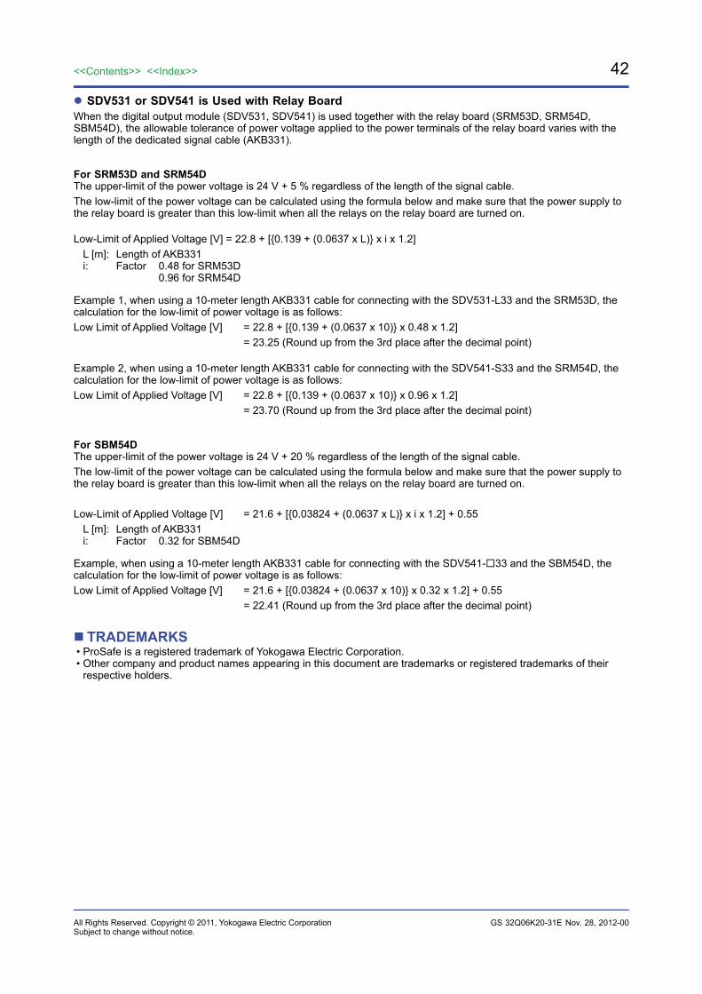
42
All Rights Reserved. Copyright © 2011, Yokogawa Electric Corporation
<<Contents>> <<Index>>
GS 32Q06K20-31E
SDV531 or SDV541 is Used with Relay BoardWhen the digital output module (SDV531, SDV541) is used together with the relay board (SRM53D, SRM54D, SBM54D), the allowable tolerance of power voltage applied to the power terminals of the relay board varies with the length of the dedicated signal cable (AKB331).
For SRM53D and SRM54DThe upper-limit of the power voltage is 24 V + 5 % regardless of the length of the signal cable.The low-limit of the power voltage can be calculated using the formula below and make sure that the power supply to the relay board is greater than this low-limit when all the relays on the relay board are turned on.
Low-Limit of Applied Voltage [V] = 22.8 + [0.139 + (0.0637 x L) x i x 1.2] L [m]: Length of AKB331 i: Factor 0.48 for SRM53D 0.96 for SRM54D
Example 1, when using a 10-meter length AKB331 cable for connecting with the SDV531-L33 and the SRM53D, the calculation for the low-limit of power voltage is as follows:Low Limit of Applied Voltage [V] = 22.8 + [0.139 + (0.0637 x 10) x 0.48 x 1.2] = 23.25 (Round up from the 3rd place after the decimal point)
Example 2, when using a 10-meter length AKB331 cable for connecting with the SDV541-S33 and the SRM54D, the calculation for the low-limit of power voltage is as follows:Low Limit of Applied Voltage [V] = 22.8 + [0.139 + (0.0637 x 10) x 0.96 x 1.2] = 23.70 (Round up from the 3rd place after the decimal point)
For SBM54DThe upper-limit of the power voltage is 24 V + 20 % regardless of the length of the signal cable.The low-limit of the power voltage can be calculated using the formula below and make sure that the power supply to the relay board is greater than this low-limit when all the relays on the relay board are turned on.
Low-Limit of Applied Voltage [V] = 21.6 + [0.03824 + (0.0637 x L) x i x 1.2] + 0.55 L [m]: Length of AKB331 i: Factor 0.32 for SBM54D
Example, when using a 10-meter length AKB331 cable for connecting with the SDV541-33 and the SBM54D, the calculation for the low-limit of power voltage is as follows:Low Limit of Applied Voltage [V] = 21.6 + [0.03824 + (0.0637 x 10) x 0.32 x 1.2] + 0.55 = 22.41 (Round up from the 3rd place after the decimal point)
TRADEMARKS• ProSafe is a registered trademark of Yokogawa Electric Corporation.• Other company and product names appearing in this document are trademarks or registered trademarks of their
respective holders.
Nov. 28, 2012-00Subject to change without notice.