Embed Size (px)
Citation preview

N001
TECHNICAL DATATROUBLE SHOOTING FOR TURNING ................................................. N002CHIP CONTROL FOR TURNING ........................................................... N004EFFECTS OF CUTTING CONDITIONS FOR TURNING ........................ N005FUNCTION OF TOOL FEATURES FOR TURNING ............................... N007FORMULAS FOR CUTTING ................................................................... N011TROUBLE SHOOTING FOR MILLING ................................................... N012FUNCTION OF TOOL FEATURES FOR FACE MILLING ..................... N013FORMULAS FOR MILLING .................................................................... N016TROUBLE SHOOTING FOR END MILLING .......................................... N017END MILL FEATURES AND SPECIFICATION ...................................... N018END MILL TYPE AND GEOMETRY ....................................................... N019PITCH SELECTION OF PICK FEED ...................................................... N020TROUBLE SHOOTING FOR DRILLING ................................................ N021DRILL WEAR CONDITION AND CUTTING EDGE DAMAGE ............... N022DRILL TERMINOLOGY AND CUTTING CHARACTERISTICS ............. N023FORMULAS FOR DRILLING .................................................................. N026TOOL WEAR AND DAMAGE ................................................................. N027MATERIAL CROSS REFERENCE LIST ................................................ N028SURFACE ROUGHNESS ....................................................................... N032HARDNESS COMPARISON TABLE ...................................................... N033CUTTING TOOL MATERIALS ................................................................ N034GRADE CHAIN ....................................................................................... N035GRADE COMPARISON TABLE ............................................................. N036INSERT CHIP BREAKER COMPARISION TABLE ............................... N042

N002
a
a a a a a
a a
a
a a
a a a
a a a a a
a a a a
a a a a
a
a a a a a a a a a
a
a a
a a
a a
a a a a a a a
a a a
a a a
TECHNICAL DATATE
CH
NIC
AL
DAT
A
TROUBLE SHOOTING FOR TURNING
Solutions
FactorsTrouble
Insert GradeSelection
Rapidinsert wear
Dimensionalunevennessduringmachining
Machining accuracynot maintainedadjustment isnecessary each time
Worseningsurfaceroughness
Cutting heat createsdeterioration inmachining accuracyand tool life
Chipping andfracturing of cutting edge
Shor
t Too
l Life
Sele
ct C
hip
Bre
aker
Wor
seni
ng D
imen
- s
iona
l Acc
urac
yPo
or S
urfa
ceFi
nish
Hea
tG
ener
atio
n
CuttingConditions
CuttingFluids
Up
Down
Style and Designof the Tool
Machine and Installation of Tool
Improper tool grade
Improper cuttingedge geometry
Improper cuttingconditions
Improper tool grade
Improper cuttingconditions
Lack of cuttingedge strength
Thermal cracking
Built-up edge
Lack of rigidity
Improper inserttolerance
Large cutting resistanceand cutting edge flank
Improper tool grade
Improper cuttingconditions
Welding occurs
Improper cuttingedge geometry
Vibration occurs
Improper cuttingconditions
Improper cuttingedge geometry
Up
Down
Sele
ct a
Har
der G
rade
Sele
ct a
Tou
gher
Gra
de
Selec
t a G
rade
with
Bet
ter
Ther
mal
Shoc
k Res
istan
ceSe
lect
a G
rade
with
Bet
ter
Adhe
sion
Res
ista
nce
Do No
t Use
Water
-so
luble C
utting
Fluid
Deter
mine
Dry
orW
et Cu
tting
Cutti
ng S
peed
Feed
Rat
e
Dept
h of
Cut
Rake
Ang
le
Corn
er R
adius
Lead
Ang
le
Honin
g Stre
ngthen
sthe
Cuttin
g Edge
C
lass
of I
nser
t(U
ngro
und-
Gro
und)
Impr
ove T
ool H
older
Rigi
dity
Inst
alla
tion
of th
e To
ol a
ndW
orkp
iece
Tool
hold
er O
verh
ang
Mac
hine
with
Inad
equa
teHo
rsep
ower
and
Rig
idity
aWet
aWet
aDry
aWet

N003
a
a a
a a a a a
a a
a a a a a
a a a a
a
a a
a a a
a a a a
a a a
a
a a
a a
a
a a
( )
TEC
HN
ICA
L D
ATA
Solutions
FactorsTrouble
Insert GradeSelection
CuttingConditions
Style and Designof the Tool
Machine and Installation of Tool
Sele
ct C
hip
Bre
akerCutting
Fluids
Up
Down
Up
Down
Sele
ct a
Har
der G
rade
Sele
ct a
Tou
gher
Gra
de
Selec
t a G
rade
with
Bet
ter
Ther
mal
Shoc
k Res
istan
ceSe
lect
a G
rade
with
Bet
ter
Adhe
sion
Res
ista
nce
Do No
t Use
Water
-so
luble C
utting
Fluid
Deter
mine
Dry
orW
et Cu
tting
Cutti
ng S
peed
Feed
Rat
e
Dept
h of
Cut
Rake
Ang
le
Corn
er R
adius
Lead
Ang
le
Honin
g Stre
ngthen
sthe
Cuttin
g Edge
C
lass
of I
nser
t(U
ngro
und-
Gro
und)
Impr
ove T
ool H
older
Rigi
dity
Inst
alla
tion
of th
e To
ol a
ndW
orkp
iece
Tool
hold
er O
verh
ang
Mac
hine
with
Inad
equa
teHo
rsep
ower
and
Rig
idity
Notch wear occurs
Improper cuttingconditions
Improper cuttingedge geometry
Improper cuttingconditions
Improper cuttingedge geometry
Vibration occurs
Improper tool grade
Improper cuttingconditions
Improper cuttingedge geometry
Vibration occurs
Improper cuttingconditions
Wide chip controlrange
Improper cuttingedge geometry
Improper cuttingconditions
Small chip controlrange
Improper cuttingedge geometry
Burr Steel, Aluminum alloy
Chipping(Cast iron)
Roughness(Mild steel)
Uncontrolled,continuous /tangled
Broken intoshort lengthsand scatter
Bur
r / C
hipp
ing
/ Rou
ghne
ssC
hip
Con
trol
aWet
aDry
aWet
aWet

N004
y
a
a
vc=165SFM vc=330SFM vc=490SFM
TECHNICAL DATATE
CH
NIC
AL
DAT
A
Type A Type
Small Depthof Cut
d <.276"
Large Depthof Cut
d=.276"─ .591"
Curl Lengthl Curless l>2inch l<2inch
1 ─ 5 Curl i 1 Curl 1 curl─half curl
Note
aIrregular con-tinuous shape
aTangle abouttool and work-piece
Good Good
aRegular con-tinuous shape
aLong chips
B Type C Type D Type E Type
CHIP CONTROL FOR TURNINGCHIP BREAKING CONDITIONS IN STEEL TURNING
Cutting Speed and Chip Control Range of Chip BreakerIn general, when cutting speed increases, the chip control range tends to become narrower.
Workpiece : AISI 1045 (180HB) Insert : TNMG332 Grade : P10Grade
Depth of Cut (inch)
Feed
( IPR
)
Feed
( IPR
)
Feed
( IPR
)
Feed
( IPR
)
Feed
( IPR
)
Depth of Cut (inch)
Coolant : Dry cutting Coolant : Wet cutting (Emulsion)
Depth of Cut (inch)
Depth of Cut (inch) Depth of Cut (inch)
Tool : MTJNR2525M16NDry Cutting
Effects of Coolant on the Chip Control Range of a Chip BreakerIf the cutting speed is the same, the range of chip control differs according to whether coolant is used or not.
Workpiece : AISI 1045Cutting Condition : vc=330SFM
aChip scatteringaChatteringaPoor finished
surfaceaMaximum

N005
y
y
a
VP15TF
UTi20T
NX2525
10 20 30 5040 60 70 80 90 100
NX3035UE6035
MP3025
MC6025
MC6015
UE6105
AP25N
1640
1310
985
655
330
UTi20T
US735 US7020
MC7025
MC7015
MP7035
HTi10NX2525
UTi20T
UE6110AP25N UC5105
10 20 30 40 60 100
16401310
985
655
490
330
260
195
UC5115
MC5015
MC5005
195
260
TEC
HN
ICA
L D
ATA
EFFECTS OF CUTTINGCONDITIONS FOR TURNING
EFFECTS OF CUTTING CONDITIONSIdeal conditions for cutting are short cutting time, long tool life, and high cutting accuracy. In order to obtain these conditions, selection of efficient cutting conditions and tool, based on work material, hardness, shape and machine capability is necessary.
CUTTING SPEEDCutting speed effects tool life greatly. Increasing cutting speed increases cutting temperature and results in shortening tool life. Cutting speed varies depending on the type and hardness of the work material. Selecting a tool grade suitable for the cutting speed is necessary.
Effects of Cutting Speed1. Increasing cutting speed by 20% decreases tool life to 1/2. Increasing cutting speed by 50% decreases tool life to 1/5.2. Cutting at low cutting speed (65―130 SFM) tends to cause chattering. Thus, tool life is shortened.
Cut
ting
Spee
d ( S
FM)
Cut
ting
Spee
d ( S
FM)
Cut
ting
Spee
d ( S
FM)
Tool Life (min)
Tool Life (min)
Tool Life (min)
P Class Grade Tool Life
M Class Grade Tool Life
K Class Grade Tool Life
WorkpieceTool Life Standard
Depth of CutFeed
HolderInsert
Dry Cutting
WorkpieceTool Life Standard
Depth of CutFeed
HolderInsert
Dry Cutting
WorkpieceTool Life Standard
Depth of CutFeed
HolderInsert
Dry Cutting
::::::
::::::
::::::
AISI 1045VB = .012inch.059inch.012IPRMCLNR-164CCNMG432
AISI 304.012inch.059inch.012IPRMCLNR-164CCNMG432MA
AISI No.45B Cast Iron.012inch.059inch.012IPRMCLNR-164CCNMG432

N006
y
y
a
a
TECHNICAL DATATE
CH
NIC
AL
DAT
A
EFFECTS OF CUTTINGCONDITIONS FOR TURNING
FEED
DEPTH OF CUT
In cutting with a general holder, feed is the distance a holder moves per workpiece revolution. In milling, feed is the distance a machine table moves per cutter revolution divided by number of inserts. Thus, it is indicated as feed per tooth. Feed rate relates to finished surface roughness.
Depth of cut is determined according to the required stock removal, shape of workpiece, power and rigidity of the machine and tool rigidity.
Effects of Feed
Effects of Depth of Cut
1. Decreasing feed rate results in flank wear and shortens tool life.
2. Increasing feed rate increases cutting temperature and flank wear. However, effects on the tool life is minimal compared to cutting speed.
3. Increasing feed rate improves machining efficiency.
1. Changing depth of cut doesn't effect tool life greatly.2. Small depths of cut result in friction when cutting the
hardened layer of a workpiece. Thus tool life is shortened.
3. When cutting uncut or cast iron surfaces, the depth of cut needs to be increased as much as the machine power allows to avoid cutting impure hard layer with the tip of cutting edge which prevents chipping and abnormal wear.
Flan
k W
ear (
inch
)Fl
ank
Wea
r (in
ch)
Feed (IPR)
Depth of Cut (inch)
Feed and Flank Wear Relationship in Steel Turning
Depth of Cut and Flank Wear Relationship in Steel Turning
Roughing of Surface Layer that Includes Uncut Surface
Cutting Conditions
Cutting Conditions
Uncut Surface
Depth of Cut
Workpiece : AISI 4340Depth of Cut ap=.040(inch)Cutting Time Tc=10min
Workpiece : AISI 4340Feed f=.008(IPR)Cutting Time Tc=10min
Grade : P10Cutting Speed vc=660(SFM)
Grade : P10Cutting Speed vc=660(SFM)

N007
y
y
a
a
(+)
(-)
vc = 655vc = 330
vc = 165TE
CH
NIC
AL
DAT
A
FUNCTION OF TOOL FEATURESFOR TURNING
RAKE ANGLE
FLANK ANGLE
Rake angle is a cutting edge angle that has large effects on cutting resistance, chip disposal, cutting temperature and tool life.
Flank angle prevents friction between flank face and workpiece resulting in smooth feed.
Positive RakeAngle
Negative RakeAngle
NegativeInsert
Positive Insert
Chip Disposal and Rake Angle
Tool
Life
(min
)
Cutting Speed (SFM)
Tool LifeStandard
VB = .016inch
Cut
ting
Tem
pera
ture
(C°)
Vert
ical
Forc
e (N
)C
uttin
gSp
eed
(SFM
) Tool Life Standard : VB = .016inch Depth of Cut : .039inch Feed = .013IPR
Cutting ResistanceVertical Force
Rake Face MeanTemperature
Depth of CutFeed
Cutting Speed
Depth of CutFeed
Cutting Speed
.079inch
.008IPR330SFM
.079inch
.008IPR330SFM
Rake Angle (°)
Cutting ConditionsWorkpiece : Alloy steel Grade : P10Dry CuttingCutting Conditions
Grade : P10Depth of Cut : .039inch Feed : .013IPR Workpiece : Alloy steel
Rake Angle and Tool Life
Effects of Rake Angle onCutting Speed, Vertical Force,
and Cutting Temperature
Effects of Rake Angle
Effects of Flank Angle
1. Increasing rake angle in the positive (+) direction improves sharpness.
2. Increasing rake angle by 1° in the positive (+) direction decreases cutting power by about 1%.
3. Increasing rake angle in the positive (+) direction lowers cutting edge strength and in the negative
(-) direction increases cutting resistance.
1. Increasing flank angle decreases flank wear occurrence.
2. Increasing flank angle lowers cutting edge strength.
When to Increase Rake Anglein the Negative (-) Direction
When to Increase Rake Anglein the Positive (+) Direction
u Hard workpiece.u When cutting edge strength is required such as in interrupted cutting and uncut surface cutting.
u Hard workpieces.u When cutting edge strength is required.
u Soft workpieces.u Workpieces suffer from work hardening easily.
u Soft workpiece.u Workpiece is easily machined.u When workpiece or the machine have poor rigidity.
Wear Depth Wear Depth
Larg
eFl
ank
Wea
r
Smal
lFl
ank
Wea
r
Small Flank Angle Large Flank AngleD.O
.C
D.O
.C
( Sam
e)
( Sam
e)
Flank angle creates a space between tool and workpiece.Flank angle relates to flank wear.
Rake Angle 6°
Fracture
Flank Angle $$
Flan
k W
ear
(inch
)
Flank Angle ($)Cutting Conditions Workpiece : Alloy steel (200HB) Grade : P20Depth of Cut : .039inch
Feed : .013IPRCutting Time : 20min
Flank Angle and Flank Wear Relationship
When to Decrease Flank Angle When to Increase Flank Angle
Rake Angle 15°
Rake Angle -10°
Rake Angle 6°

N008
AA
a
a'
y
a
a
a
y
y
(–)
f =
KAPR = 0°
h
B
f =
KAPR = 15°
0.97h
1.04
B
f =
KAPR = 30°
0.87h
1.15
B
TECHNICAL DATATE
CH
NIC
AL
DAT
A
FUNCTION OF TOOL FEATURESFOR TURNING
SIDE CUTTING EDGE ANGLE (LEAD ANGLE)Side cutting edge angle lower impact load and effect feed force, back force, and chip thickness.
Same Same Same
B : Chip Width f : Feed h : Chip ThicknessKAPR : Tool Cutting Edge Angle
Side Cutting Edge Angle and Chip Thickness
Workpiece : Alloy steel Grade : P20Depth of Cut : .118inch Feed : .008IPR
Dry Cutting
Side Cutting Edge Angle 15°
Side Cutting Edge Angle 0°
Tool
Life
(min
)
Cutting Speed (SFM)
Side Cutting Edge and Tool Life
Effects of Side Cutting Edge Angle (Lead Angle)
Effects of End Cutting Edge Angle
Effects of Cutting Edge Inclination
1. At the same feed rate, increasing the side cutting edge angle increases the chip contact length and decreases chip thickness. As a result, the cutting force is dispersed on a longer cutting edge and tool life is prolonged. (Refer to the chart.)2. Increasing the side cutting edge angle increases force a'. Thus, thin, long workpieces suffer from bending in some cases.3. Increasing the side cutting edge angle decreases chip control.4. Increasing the side cutting edge angle decreases the chip thickness and increases chip width. Thus, breaking chips is difficult.
When to Decrease Lead Angle When to Increase Lead Angle
uFinishing with small depth of cut.uThin, long workpieces.uWhen the machine has poor rigidity.
uHard workpieces which produce high cutting temperature.uWhen roughing a large diameter workpiece.uWhen the machine has high rigidity.
Receive force A. Force A is dividedinto a and a'.
End CuttingEdge Angle
Back Relief Angle Side Flank Angle
Cutting EdgeInclination
True RakeAngle
End Cutting EdgeAngle
Main Cutting Edge Corner Radius
END CUTTING EDGE ANGLE
CUTTING EDGE INCLINATION
End cutting edge angle prevents wear on tool and workpiecesurface and is usually 5°― 15°.
1. Decreasing the end cutting edge angle increases cutting edge strength, but it also increases cutting edge temperature.2. Decreasing the end cutting edge angle increases the back force and can result in chattering and vibration while machining.3. Small end cutting edge angle in roughing and large angle in finishing are recommended.
1. Negative (-) cutting edge inclination disposes chips in the workpiece direction, and positive (+) disposes chips in the opposite direction.2. Negative (-) cutting edge inclination increases cutting edge strength, but it also increases back force of cutting resistance. Thus, chattering easily occurs.
Cutting edge inclination indicates inclination of the rake face. In heavycutting, the cutting edge receives extremely large shock at the beginningof cutting. Cutting edge inclination keeps the cutting edge from receivingthis shock and prevents fracturing. 3°― 5° in turning and 10°― 15° in millingare recommended.
Side Cutting Edge Angle

N009
y
a
EDR
TEC
HN
ICA
L D
ATA
HONING AND LAND
Effects of Honing
Honing and land are cutting edge shapes thatmaintain cutting edge strength.Honing can be round or chamfer type. Theoptimal honing or / and land width is approximately 1/2 of the feed.Land is the narrow flat area on the rake orflank face.
Honing Angle
Round Honing Chamfer Honing Flat Land
Tool
Life
(Num
ber o
f Im
pact
s)
Tool
Life
(min
)Round HoningChamfar Honing
Round HoningChamfar Honing
Round HoningChamfar Honing
Honing Size (inch)
Honing Size (inch)
Honing Size (inch)
Workpiece : Alloy steel (280HB) Grade : P10Cutting Conditions : vc=655SFM ap=.059inch f=.013IPR
Workpiece : Alloy steel (220HB) Grade : P10Cutting Conditions : vc=525SFM ap=.059inch f=.018IPR
Workpiece : Alloy steel (220HB) Grade : P10Cutting Conditions : vc=333SFM ap=.059inch f=.017IPR
Honing Size and Tool LifeDue to Wear
Honing Size and Tool LifeDue to Fracturing
Prin
cipa
l For
ce (N
)Fe
ed F
orce
(N)
Bac
k Fo
rce
(N)
Honing Size and Cutting Resistance
1.Enlarging the honing increases cutting edge strength, and reduces fracturing.2.Enlarging the honing increases flank wear occurrence. Honing size doesn't affect rake wear.3.Enlarging the honing increases cutting resistance and chattering.
When to Decrease Honing Size When to Increase Honing Size
u When finishing with small depth of cut and small feed.u Soft workpieces.u When the workpiece and the machine have poor rigidity.
u Hard workpieces.u When the cutting edge strength is required such as for uncut surface cutting and interrupted cutting.u When the machine has high rigidity.
Honing Width Honing Width Land Width
N010
y
a
a
R1
TECHNICAL DATATE
CH
NIC
AL
DAT
A
FUNCTION OF TOOL FEATURESFOR TURNING
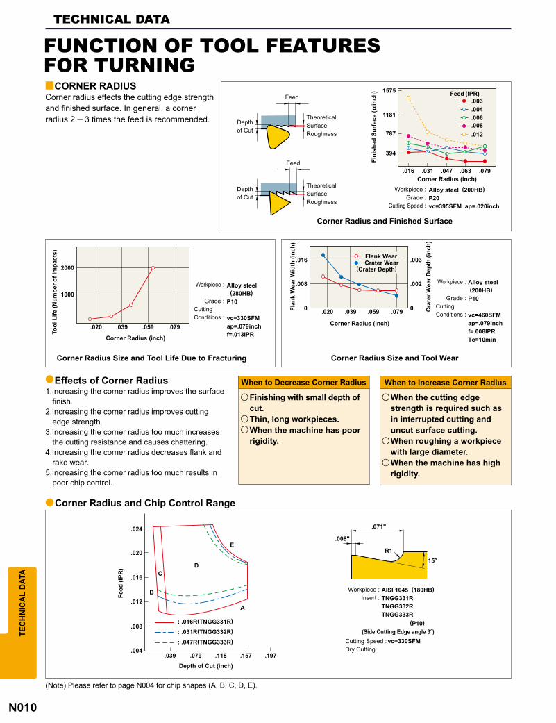
CORNER RADIUSCorner radius effects the cutting edge strengthand finished surface. In general, a cornerradius 2 ― 3 times the feed is recommended. Depth
of Cut
Depthof Cut
Feed
Feed
TheoreticalSurfaceRoughness
TheoreticalSurfaceRoughness
Fini
shed
Sur
face
(!in
ch) Feed (IPR)
Corner Radius (inch) Workpiece : Alloy steel (200HB) Grade : P20 Cutting Speed : vc=395SFM ap=.020inch
Corner Radius and Finished Surface
Tool
Life
(Num
ber o
f Im
pact
s)
Corner Radius (inch)
Workpiece : Alloy steel (280HB) Grade : P10Cutting Conditions : vc=330SFM ap=.079inch f=.013IPR
Workpiece : Alloy steel (200HB) Grade : P10Cutting Conditions : vc=460SFM ap=.079inch f=.008IPR Tc=10min
Corner Radius Size and Tool Life Due to Fracturing Corner Radius Size and Tool Wear
Flan
k W
ear W
idth
(inc
h)
Corner Radius (inch)
Flank Wear Crater Wear(Crater Depth)
Cra
ter W
ear D
epth
(inc
h)
Effects of Corner Radius
Corner Radius and Chip Control Range
1.Increasing the corner radius improves the surface finish.2.Increasing the corner radius improves cutting edge strength.3.Increasing the corner radius too much increases the cutting resistance and causes chattering.4.Increasing the corner radius decreases flank and rake wear.5.Increasing the corner radius too much results in poor chip control.
When to Decrease Corner Radius When to Increase Corner Radius
uFinishing with small depth of cut.uThin, long workpieces.uWhen the machine has poor rigidity.
uWhen the cutting edge strength is required such as in interrupted cutting and uncut surface cutting.uWhen roughing a workpiece with large diameter.uWhen the machine has high rigidity.
Feed
(IPR
)
Depth of Cut (inch)
Workpiece : AISI 1045 (180HB) Insert : TNGG331R TNGG332R TNGG333R (P10)
(Side Cutting Edge angle 3°)Cutting Speed : vc=330SFM Dry Cutting
(Note) Please refer to page N004 for chip shapes (A, B, C, D, E).

N011
y
y y
y
(SFM) (IPR)
(min)
365SFM .009IPR
øDm n
lf
n
8RE
TEC
HN
ICA
L D
ATA
CUTTING SPEED (vc)
CUTTING TIME (Tc) THEORETICAL FINISHED SURFACE ROUGHNESS (h)
FEED (f)
FORMULAS FOR CUTTINGvc (SFM) : Cutting SpeedDm (inch) : Workpiece Diameter) (3.14) : Pin (min-1) : Main Axis Spindle Speed
Tc (min) : Cutting TimeIm (inch) : Workpiece LengthI (inch/min) : Cutting Length per Min.
h (!inch) : Finished Surface Roughnessf (IPR) : Feed per RevolutionRE (inch) : Insert Corner Radius
f (IPR) : Feed per RevolutionI (inch/min) : Cutting Length per Min.n (min-1) : Main Axis Spindle Speed
(Problem) What is the cutting speed when the main axis spindle speed is 700 min-1 and external diameter is &2" ?
(Problem) What is the cutting time when 4 inch workpiece is machined at 1000min-1 with feed= .008IPR ?
(Problem) What is the theoretical finished surface roughness when the insert corner radius is .031inch and feed is .008IPR ?
(Problem) What is the feed per revolution when the main axis spindle speed is 500min-1 and cutting length per minute is 4.72 inch/min ?
(Answer) Substitute )=3.14, Dm=2, n=700 into the formula.
(Answer) First, calculate the cutting length per min. from the feed and spindle speed. (Answer) Substitute f= .008 IPR, RE= .031 into the formula.
(Answer) Substitute n=500, I=4.72 into the formula.
The answer is 365SFM. The answer is .009IPR.
I = f ×n = .008×1000 = 8inch/minSubstitute the answer above into the formula.
Tc = = = 0.5minIml
48
0.5x60=30 (sec.) The answer is 30 sec.
(!inch)
The answer is 258!inch.
!inch
Depthof Cut
Depthof Cut
TheoreticalSurfaceRoughness
TheoreticalSurfaceRoughness
Feed Feed

N012
a
a a a a
a
a
a a
a
a a a a a
a a a a
a a a a
a a a a
a a a a a
a a
a a a a a a a a a a a
a a a a a a a
a a a a
a a a a
a a a
a a
a a
a
a a
a a
a
a a a a a a a a a a a
a
a a
a
a a a
TECHNICAL DATATE
CH
NIC
AL
DAT
A
TROUBLE SHOOTING FOR MILLING
Solutions
Trouble
Factors
Insert GradeSelection
Enga
ge A
ngle
Shor
t Too
l Llfe
Poor
Sur
face
Fin
ish
Bur
r / C
hipp
ing
Chi
p C
ontr
ol
CuttingConditions
CuttingFluids
Up
Down
Up
Down
Style and Designof the Tool
Machine and Installation of Tool
Sele
ct a
Har
der G
rade
Sele
ct a
Tou
gher
Gra
deSe
lect a
Gra
de w
ith B
ette
rTh
erm
al Sh
ock R
esist
ance
Sele
ct a
Gra
de w
ith B
ette
rAd
hesi
on R
esis
tanc
eCu
tting
Spe
ed
Feed
Rat
e
Dept
h of
Cut
Do No
t Use
Water
-so
luble C
utting
Fluid
Deter
mine
Dry
orW
et Cu
tting
Rake
Ang
le
Corn
er A
ngle
Honin
g Stre
ngthen
sthe
Cuttin
g Edge
C
utte
rD
iam
eter
Decr
ease
the N
umbe
r of T
eeth
Wid
er C
hip
Pock
et
Use
of a
Wip
er In
sert
Run
-out
Acc
urac
y
Impr
ove
Cut
ter R
igid
ity
Inst
alla
tion
of th
e To
ol a
ndW
orkp
iece
Shor
ten
Tool
Ove
rhan
g
Mac
hine
with
Inad
equa
teHo
rsep
ower
and
Rig
idity
Improper tool grade
Improper cuttingedge geometryImproper cuttingconditions
Improper tool grade
Improper cuttingconditionsLack of cuttingedge strengthThermal crackingoccursBuilt-up edgeoccurs
Lack of rigidity
Improper cuttingconditions
Welding occurs
Poor run-outaccuracy
Vibration occurs
Workpiecebending
Tool clearance
Large backforceChip thicknessis too largeCutter diameteris too large
Poor sharpness
A large cornerangleImproper cuttingconditions
Poor sharpness
Corner angle istoo small
Vibration occurs
Welding occurs
Chip thicknessis too thinCutter diameteris too smallPoor chipdisposal
Rapidinsert wear
Chipping andfracturing of cutting edge
Worseningsurfaceroughness
Not parallelor irregularsurface
Burr
Chipping
Poor chip disposal, chip jammingand chip packing
aWet
aWet
aWet
aDry
aWet
Up

N013
GAMF
GAMP
KAPR
T
I
a ─ a
─ a a
a ─ ─
a ─ a
y
y
y
a a
0°
15°
45°ae
ap
(GAMP)
(GAMF)
(KAPR)
TEC
HN
ICA
L D
ATA
FUNCTION OF TOOL FEATURESFOR FACE MILLING
FUNCTION OF EACH CUTTING EDGEANGLE IN FACE MILLING
STANDARD INSERTS
CORNER ANGLE (KAPR) AND CUTTING RESISTANCE
Corner Angle
Wiper Edge
True Rake Angle
Radial Rake Angle
Main Cutting Edge
LeadAngle
Axial Rake Angle
Cutting Edge Inclination
Each Cutting Edge Angle in Face Milling
Positive and Negative Rake Angle Standard Cutting Edge Shape
NegativeRake Angle
NeutralRake Angle
PositiveRake Angle
· Insert shape whose cutting edge precedes is a positive rake angle.· Insert shape whose cutting edge follows is a negative rake angle.
Axial Rake Angle
Radial Rake Angle Radial Rake Angle
Double Positive(DP Edge Type)
Double Negative(DN Edge Type)
Negative/Positive(NP Edge Type)
Cut
ting
Res
ista
nce
( N) Corner Angle : 0° Corner Angle : 15° Corner Angle : 45°
PrincipalForce
Feed Force
Back Force
Back Force
Back Force
Feed Force Feed Force
PrincipalForce
PrincipalForce
fz(IPT) fz(IPT) fz(IPT)Workpiece :
Tool : Cutting Conditions :
Alloy Steel (281HB)ø4" Single Insert vc=410SFM ap=.157inch ae=4.33inch
Cutting Resistance Comparison betweenDifferent Corner Angles
Principal Force
Feed Force
Table Feed
Back Force
Three Cutting Resistance Forces in Milling
Corner Angle
Corner Angle
Corner Angle
Back force is in the minusdirection. Lifts the workpiece whenworkpiece clamp rigidity is low.
Corner angle 15° is recommended for face milling of workpieces with low rigidity such as thin workpieces.
The largest back force. Bends thin workpieces and lowers cutting accuracy.
* Prevents workpiece edge chipping in cast iron cutting.
* Principal force: Force is in the opposite direction of face milling rotation.
* Back force: Force that pushes in the axial direction.
* Feed Force: Force is in the feed direction and is caused by table feed.
Axial Rake Angle Axial Rake Angle
Radial Rake Angle
Type of Angle Symbol FunctionDetermines chip disposal direction.
Determines sharpness.
Determines chip thickness.
Determines actual sharpness.
Determines chip disposal direction.
Effect
Positive : Excellent machinability.
Negative : Excellent chip disposal.
Large : Thin chips and small cutting impact. Large back force.
Positive(large) : Excellent machinability. Minimal welding.Negative(large) : Poor machi-nability. Strong cutting edge.
Positive (large) : Excellent chip disposal. Low cutting edge strength.
Axial Rake Angle
Radial Rake Angle
Corner Angle
True Rake Angle
Cutting EdgeInclination
Standard CuttingEdge Combinations
Axial Rake Angle (GAMP) Positive ( + )
Positive ( + )
Positive Insert (One Sided Use) Negative Insert (Double Sided Use)
Negative ( – ) Negative ( – )
Positive Insert (One Sided Use)
Negative ( – ) Positive ( + )
Radial Rake Angel (GAMF)
Insert Used
Steel
Cast Iron
Aluminum Alloy
Difficult-to-Cut MaterialWor
k M
ater
ial
Corner Angle 15°
Corner Angle 45°
Corner Angle 0°

N014
vc=330SFMTc=69min
vc=410SFMTc=55min
vc=525SFMTc=31min
ya
y
a
KAPR KAPR KAPR
TECHNICAL DATATE
CH
NIC
AL
DAT
A
0° Corner Angle 15° Corner Angle 45° Corner Angle
FUNCTION OF TOOL FEATURESFOR FACE MILLING CORNER ANGLE AND TOOL LIFE Corner Angle and Chip Thickness When the depth of cut and feed per tooth, fz, are fixed, the larger the corner angle (KAPR) is, then the thinner the chip thickness (h) becomes (for a 45° KAPR, it is approx. 75% that of a 0° KAPR). This can be seen in below. Therefore as the KAPR increases, the cutting resistance decreases resulting in longer tool life. Note however, if the chip thickness is too large then the cutting resistance can increase leading to vibrations and shortened tool life.
UP CUT AND DOWN CUT MILLING Which method to be used will depend on the machine and the face mill cutter that has been selected. Generally down cut machining offers longer tool life than up cut milling.
Corner Angle and Crater Wear Below shows wear patterns for different corner angles. When comparing crater wear for 0° and 45° corner angles, it can be clearly seen that the crater wear for 0° corner angle is larger. This is because if the chip thickness is relatively large, the cutting resistance increases and so promotes crater wear. As the crater wear develops then cutting edge strength will reduce and lead to fracturing.
Effects on chip thickness due to the variation of corner angles
Workpiece :Tool :
Insert :Cutting Conditions :
Coolant :
AISI 4340 (287HB)DC=4.92inchM20ap=.118inchae=4.33inchfz=.008IPTDry Cutting
Up Cut Milling Down Cut MillingTool rotation Tool rotation
Milling cutter inserts Milling cutter inserts
Portion machined
Portion machinedWorkpiecemovementdirection
Workpiecemovementdirection

N015
y a
a
Run-out
D.O
.C
TEC
HN
ICA
L D
ATA
FINISHED SURFACECutting Edge Run-out Accuracy
Improve Finished Surface Roughness
Minor Cutting Edge
PeripheralCutting Edge
Cutting Edge Run-out andAccuracy in Face Milling
Cutting edge run-out accuracy of indexable inserts on the cutter body greatly affects the surface finish and tool life.
Large
Small
Poor Finished Surface
Good Finished Surface
Chipping Due to Vibration
Rapid Wear Growth
Stable Tool Life
Usually the minor cutting edges are set parallel to the face of a milling cutter and theoretically the finished surface accuracy should be maintained, even if run-out accuracy is poor.
Cutting Edge No.
Feed per ToothFeed per Revolution
Sub Cutting Edge Run-outand Finished Surface
Actual Problems· Cutting edge run-out.· Minor cutting edge inclination.· Cutter body accuracy.· Spare parts accuracy.· Welding, vibration, chattering.
Countermeasure
Wiper Insert
* Machine a surface that has already been machined by normal insert in order to produce smooth finished surface.
· Replace one normal insert with wiper insert. · Wiper inserts are set to protrude by .0012 ― .004 inch from the standard inserts.
Table Feed
Shorten Tool Life
Value depends on the cutting edge and insert combination.

N016
vc =
fz = vfz • n
12(SFM)
vc =
fz =
=
=
) • DC • n12 12
3.14 x 5" x 350 = 457.9 SFM
= .004 IPT
(IPT)
Vfz x n
2010 x 500
Tc = Lvf
(min)
Tc = 2032
= 0.625 (min)
y
y
y
y
L
I
) • DC • n
DC
DC
TECHNICAL DATATE
CH
NIC
AL
DAT
A
FORMULAS FOR MILLINGCUTTING SPEED (vc)
FEED PER TOOTH (fz)
TABLE FEED (vf)
CUTTING TIME (Tc)
vc (SFM) : Cutting Speed DC (inch) : Cutter Diameter) (3.14) : Pi n (min-1) : Main Axis Spindle Speed
(Problem) What is the cutting speed when main axis spindle speed is 350min-1
and cutter diameter is &5" ?(Answer) Substitute ) 3.14, DC=5", n=350 into the formula.
The answer is 457.9SFM.
fz (IPT) : Feed per Tooth z : Insert Numbervf (inch/min) : Table Feed per Min.n (min-1) : Main Axis Spindle Speed (Feed per Revolution fr=z x fz)
vf (inch/min) : Table Feed per Min.fz (IPT) : Feed per Tooth z : Insert Numbern (min-1) : Main Axis Spindle Speed
Tc (min) : Cutting Timevf (inch/min) : Table Feed per Min.L (inch) : Total Table Feed Length (Workpiece Length(l )+Cutter Diameter(DC))
FeedDirection
Feed per Tooth Tooth MarkWiper Edge Angle
(Problem) What is the feed per tooth when the main axis spindle speed is 500min-1, insert number is 10, and table feed is 20inch/min ?
(Answer) Substitute the above figures into the formula.
(Problem) What is the table feed when feed per tooth is .004IPT, with 10 inserts and main axis spindle speed is 500min-1?(Answer) Substitute the above figures into the formula. vf = fz x z x n = .004IPT x 10 x 500 = 20inch/min The answer is 20inch/min.
(Problem) What is the cutting time required for finishing 4" width and 12" length surface of a cast iron (GG20) block when cutter diameter is &8", the number of inserts is 16, the cutting speed is 410SFM, and feed per tooth is .01". (spindle speed is 200min-1)(Answer) Calculate table feed per min vf=.01 x 16 x 200=32inch/min Calculate total table feed length. L=12+8=20inch Substitute the above answers into the formula.
The answer is .004IPT.
vf = fz • z • n (inch/min)
0.625 x 60 = 37.5 (sec.) The answer is 37.5 sec.

N017
a
a
a a
a
a a
a a a a a a
a
a a
a a
a a
a a
a a a a
a a a a a a
a
a a
a a
a a a
a
a
a a
a a a a
a a a
a a a a a a
a a
a
a
a a
a a
a a
TEC
HN
ICA
L D
ATA
TROUBLE SHOOTING FOR END MILLING
Solutions
Insert GradeSelection
CuttingFluids
Large wearat the peripheralcutting edge
Chipping
Breakageduringcutting
Vibrationduringcutting
Poor wallsurfaceroughness
Poor bottomsurfaceroughness
Out ofvertical
Poor surfacefinishaccuracy
Burr,workpiece chipping
Quick burrformation
Chip packing
Cutting Conditions Style and Designof the Tool
Machine andInstallation of Tool
FactorsTrouble
Impr
ove
End
Mill
Rig
idity
Wid
er C
hip
Pock
et
Shor
ten
Tool
Ove
rhan
g
Tool
Inst
alla
tion
Accu
racy
Spind
le Co
llet R
un-ou
t Acc
uracy
Colle
t Insp
ectio
n and
Exch
ange
Increa
se Ch
uck C
lampin
g Pow
er
Mac
hine
Sta
bilit
y, Ri
gidi
ty
Hel
ix A
ngle
Numb
er of
Flutes
Conc
avity
Angle
ofEn
d Cutt
ing Ed
ge
Tool
Dia
met
er
Cutti
ng S
peed
Feed
Rat
e
Dept
h of
Cut
Decr
ease
Pic
k Fe
ed R
ate
Dow
n C
ut
Air
Blo
w
Coa
ted
Tool
Shor
t Too
l Life
Poor
Sur
face
Fin
ish
Burr /
Chipp
ing / B
urrs
Chip C
ontrol
Incr
ease
Coo
lant
Qua
ntity
Do N
ot Us
e Wate
r-so
luble
Cuttin
g Flui
dDe
term
ine
Dry
orW
et C
uttin
g Up
Down
Up
Down
Non-coated insertis used
Not enough flutes
Improper cuttingconditions
Up cut milling
Improper cuttingconditions
Fragile cutting edge
Insufficient clampingforcePoor clampingrigidityImproper cuttingconditions
Poor end mill rigidity
Overhang longerthan necessary
Chip packing
Improper cuttingconditions
Poor end mill rigidity
Poor clampingrigidityLarge cuttingedge wearImproper cuttingconditions
Chip jamming
The end cutting edge doesnot have a concave angle
Large pick feed
Large cuttingedge wearImproper cuttingconditions
Poor end mill rigidity
Improper cuttingconditionsPoor clampingrigidityImproper cuttingconditions
Large helix angle
Notch wear occurs
Improper cuttingconditionsMetal removaltoo largeLack of flutechip space
DownCut
aWet

N018
y
y
y
TECHNICAL DATATE
CH
NIC
AL
DAT
A 2-flutes
Effective chip disposal.Horizontal feed millingpossible.
Low rigidity.
Various cutting modesincluding slotting, shouldermilling and drilling.
3-flutes
Effective chip disposal.Horizontal feed millingpossible.
Diameter is notmeasured easily.
Slotting, shoulder millingHeavy cutting, finishing
4-flutes
High rigidity.
Chip disposal is poor.
Shallow slotting, shouldermilling Finishing
6-flutes
High rigidity.Superior cuttingedge durability.
Chip disposal is poor.
Machining hardened steels.Shallow slotting, shouldermilling.
Feat
ure Adva
ntage
Faul
tU
sage
END MILL FEATURES AND SPECIFICATIONNOMENCLATURE
COMPARISON OF SECTIONAL AREA OF CHIP POCKET
CHARACTERISTICS AND APPLICATIONS OF DIFFERENT-NUMBER-OF-FLUTE END MILLS
Cutter sweep Neck
Shank (Handle)
Shank diameter
Peripheral cutting edge
Helix angle
Length of cut
Radial primary relief angle
Axial secondary clearance angle
Axial primary relief angle
Axial rake angle
End cutting edge
Corner Concavity angle of end cutting edge
End gash
Relief width (Flank width)
Overall length
Radial rake angle
Radial secondary clearance angle
Body (Cutting part)
Diameter
Land width
2-flutes50%
3-flutes45%
4-flutes40%
6-flutes20%

N019
y
y
y
TEC
HN
ICA
L D
ATA
Type
Type
Type
Ordinary FluteRegular flute geometry as shown is most commonly used for roughing and finishing of side milling, slotting and shoulder milling.
A tapered flute geometry is used for special applications such asmould drafts and for applying taper angles after conventional straight edged milling.
Roughing type geometry has a wave like edge form and breaks the material into small chips. Additionally the cutting resistance is low enabling high feed rates when roughing. The inside face of the flute is suitable for regrinding.
Special form geometry as shown is used for producing corner radii oncomponents. There are an infinite number of different geometry's that can be manufactured using such style of cutters.
Generally used for side milling, slotting and shoulder milling. Plunge cutting is not possible due to the center hole that is used to ensure accurate grinding and regrinding of the tool.
Generally used for side milling, slotting and shoulder milling. Plunge cutting is possible and greater plunge cutting efficiency is obtained when using fewer flutes. Regrinding on the flank face can be done.
Geometry completely suited for curved surface milling. At the extreme end point the chip pocket is very small leading to inefficient chip evacuation.
Used for radius profiling and corner radius milling. When pick feed milling an end mill with a large diameter and small corner radius canbe efficiently used.
Most widely used type.
Long shank type for deep pocket and shoulder applications.
Long neck geometry can be used for deep slotting and is also suitable for boring.
Long taper neck features are best utilized on deep slotting and mold draft applications.
Tapered Flute
Roughing Flute
Formed Flute
Square End (With Center Hole)
Square End (Center Cut)
Ball End
Corner Radius End
Standard (Straight Shank)
Long Shank
Long Neck
Taper Neck
Shape
Shape
Shape
Feature
Feature
Feature
END MILL TYPE AND GEOMETRYPERIPHERAL CUTTING EDGE
END CUTTING EDGE
SHANK AND NECK PARTS

N020
P
R .004 .008 .012 .016 .020 .024 .028 .031 .035 .039
0.5 .0001 .0004 .0009 .0017 .0026 .0039 ─ ─ ─ ─
1 .00004 .0002 .0004 .0008 .0016 .0018 .0025 .0033 .0042 ─
1.5 .00004 .0001 .0003 .0005 .0008 .0012 .0016 .0021 .0027 .0034
2 .00004 .0001 .0002 .0004 .0006 .0009 .0012 .0016 .0020 .0025
2.5 .00004 .00007 .0002 .0003 .0005 .0007 .0010 .0013 .0016 .0020
3 .00007 .0002 .0003 .0004 .0006 .0008 .0011 .0013 .0017
4 .00004 .0001 .0002 .0003 .0004 .0006 .0008 .0010 .0012
5 .00004 .00007 .0002 .0002 .0004 .0005 .0006 .0008 .0010
6 .00004 .00007 .0001 .0002 .0003 .0004 .0005 .0007 .0008
8 .00004 .0001 .0002 .0002 .0003 .0004 .0005 .0006
10 .00004 .00007 .0001 .0002 .0002 .0003 .0004 .0005
12.5 .00004 .00007 .0001 .0002 .0002 .0002 .0003 .0004
P
R .043 .047 .051 .055 .059 .063 .067 .071 .075 .079
0.5 ─ ─ ─ ─ ─ ─ ─ ─ ─ ─
1 ─ ─ ─ ─ ─ ─ ─ ─ ─ ─
1.5 .0041 ─ ─ ─ ─ ─ ─ ─ ─ ─
2 .0030 .0036 .0043 ─ ─ ─ ─ ─ ─ ─
2.5 .0024 .0029 .0034 .0039 ─ ─ ─ ─ ─ ─
3 .0020 .0024 .0028 .0033 .0037 .0043 ─ ─ ─ ─
4 .0015 .0018 .0021 .0024 .0028 .0032 .0036 .0041 ─ ─
5 .0012 .0014 .0017 .0019 .0022 .0025 .0029 .0032 .0036 .0040
6 .0010 .0012 .0014 .0016 .0019 .0021 .0024 .0027 .0030 .0033
8 .0007 .0009 .0010 .0012 .0014 .0016 .0018 .0020 .0022 .0025
10 .0006 .0007 .0008 .0010 .0011 .0013 .0014 .0016 .0018 .0020
12.5 .0005 .0006 .0007 .0008 .0009 .0010 .0011 .0013 .0014 .0016
End mill
h=R ▪ 1─cos sin-1
y
y
TECHNICAL DATATE
CH
NIC
AL
DAT
A
PITCH SELECTION OF PICK FEEDPICK FEED MILLING (CONTOURING) WITH BALL NOSE END MILLS, END MILLS WITH CORNER RADIUS
CORNER R OF END MILLS AND CUSP HEIGHT BY PICK FEED
R : Radius of Ball Nose(PRFRAD), Corner Radius(RE)
P : Pick Feed
h : Cusp Height
Unit : inch
Pitch of Pick Feed (P)
Pitch of Pick Feed (P)

N021
a a
a
a a
a
a
a a a
a
a a
a a
a a a a
a
a
a a a a
a a
a
a a a
a
a
a a
a a
a
a a
a
a
a a
a
a
a a
a a a a
a a a
a a a a
a
TEC
HN
ICA
L D
ATA
TROUBLE SHOOTING FOR DRILLINGCutting Conditions
Drill breakage
Large wearat the peripheralcutting edge
Chipping ofthe peripheralcutting edge
Chisel edgechipping
Hole diameterincreases
Hole diameterbecomessmaller
Poorstraightness
Poor holepositioningaccuracy, roundness andsurface finish
Burrs at thehole exit
Long chips
Chip packing
CuttingFluids
Large
Small
Style and Designof the Tool
Machine andInstallation of Tool
Solutions
FactorsTrouble
Shor
ten
the
Flut
e Le
ngth
Decr
ease
the
Lip
Heig
ht
Use a
Dril
l with
Coo
lant H
oles
Cha
nge
to a
Dril
l with
X Ty
pe T
hinn
ing
Tool
Inst
alla
tion
Accu
racy
Shor
ten
Tool
Ove
rhan
g
Flat
ten
the W
orkp
iece F
ace
Workp
iece I
nstal
lation
Accu
racy
Mac
hine
Sta
bilit
y, Ri
gidi
ty
Chis
el W
idth
Honi
ng W
idth
Core
Thick
ness
Incr
ease
Oil
Rat
io
Incr
ease
Vol
ume
Incr
ease
Coo
lant
Pres
sure
Lowe
r the
Feed
at In
itial E
ntry
Lowe
r the
Feed
whe
n Exit
ing
Step
Fee
dIn
crea
se th
e Acc
urac
y an
dth
e De
pth
of th
e Pr
e-ho
le
Cutti
ng S
peed
Feed
Rat
e
Up
Down
Lack of drillrigidityImproper cuttingconditionsLarge deflectionof the tool holderWorkpiece faceis inclinedImproper cuttingconditionsIncrease in temp.at cutting pointPoor run-outaccuracylmproper cuttingconditionsLarge deflectionof the tool holderChattering,vibrationThe chisel edgewidth is too large
Poor entry
Chattering,vibrationLack of drillrigidityImproper drillgeometryIncrease in temp.at cutting pointImproper cuttingconditionsImproper drillgeometryLack of drillrigidityLarge deflectionof the tool holderPoor guidingpropertiesLack of drillrigidity
Poor entry
Improper cuttingconditionsLarge deflectionof the tool holderImproper drillgeometryImproper cuttingconditionsImproper cuttingconditionsPoor chipdisposalImproper cuttingconditionsPoor chipdisposal
Shor
t Too
l Life
Poor
Hol
e A
ccur
acy
Bur
rC
hip
Con
trol

N022
We
Wf
WoW
m'
Wm
y
y
b
a c
a
b
c
TECHNICAL DATATE
CH
NIC
AL
DAT
A
DRILL WEAR CONDITION
CUTTING EDGE DAMAGE
We : Chisel edge wear width
Wf : Flank wear width (The middle of the cutting edge)
Wo : Outer corner wear width
Wm : Margin wear width
Wm' : Margin wear width (Leading edge)
When drilling, the cutting edge of the drill can suffer from chipping, fracture and abnormal damage. In such cases it is important totake a closer look at the damage, investigate the cause and take countermeasures.
DRILL WEAR CONDITIONAND CUTTING EDGE DAMAGEThe diagram below shows a simple drawing depicting the wear of a drill's cutting edge. The generation and the amount of wear differaccording to the workpiece materials and cutting conditions used. But generally, the peripheral wear is largest and determines a drilltool life. When regrinding, the flank wear at the point needs to be ground away completely. Therefore, if there is large wear, morematerial needs to be ground away to renew the cutting edge.

N023
y
y
TEC
HN
ICA
L D
ATA
NAMES OF EACH PART OF A DRILL
SHAPE SPECIFICATION AND CUTTING CHARACTERISTICS
DRILL TERMINOLOGYAND CUTTING CHARACTERISTICS
Point length
Clearance angle
Helix angle
Point angle
Flute length
Overall length
Margin width
Margin
Chisel edge angle
Land width
Cutting edge
Flute widthFlute
Body clearance
Depth of body clearance
Lead Straight cylindrical shank
Shank length
Flank
Outer corner
Drill diameter
Shankdiameter
High-hardness material Small Large Soft material (Aluminum, etc.)
Soft material with good machinability Small Large For hard material and high-efficiency machining
Low cutting resistanceLow rigidityGood chip disposal performanceMachinable material
Large cutting resistanceHigh rigidityPoor chip disposalHigh-hardness material,cross hole drilling, etc.
Poor guiding performance Small Margin width Large Good guiding performance
Rake Angle
Point angle
Thin Web thickness Thick
Helix Angle
Flute Length
Point Angle
Web Thickness
Margin
DiameterBack Taper
Is the inclination of the flute with respect to the axial direction of a drill, which corresponds to the rake angle. The rakeangle of a drill differs according to the position along the cutting edge. The rake angle is largest at the periphery andsmallest towards the center of the cutting edge. The chisel edge has a negative rake angle, crushing the work.
In general, the angle is 118° for high speed steel drills and 130─140° for carbide drills.
The margin determines the drill diameter and functions as a drill guide during drilling. The margin width is decided taking into consideration the friction within the hole to be drilled.
It is an important element that determines the rigidity and chip disposal performance of a drill. The web thickness is set according to applications.
To reduce friction with the inside of the drilled hole, the portion from the point to the shank is tapered slightly. The degree is usually represented by the quantity of reduction in the diameter with respect to the flute length, which is approx. .0016"─ .016"/4".
It is determined by depth of hole, guide bush length, and regrinding allowance. Since the influence on the tool life is great, it is necessary to minimize it as much as possible.
Functional length
Center line

N024
y
a
y
TECHNICAL DATATE
CH
NIC
AL
DAT
A
DRILL TERMINOLOGYAND CUTTING CHARACTERISTICS
CUTTING EDGE GEOMETRY AND ITS INFLUENCE
Typical Cutting Edge Geometries
As shown in table below, it is possible to select the most suitable cutting edge geometry for different applications. If the most suitable cutting edge geometry is selected then higher machining efficiency and higher hole accuracy can be obtained.
WEB THINNINGThe rake angle of the cutting edge of a drill reduces toward the center, and it changes into a negative angle at the chisel edge. During drilling, the center of a drill crushes the work, generating 50─70% of the cutting resistance. Web thinning is very effective for reduction in the cutting resistance of a drill, early removal of cut chips at the chisel edge, and better initial bite.
Grinding Name
Conical
Flat
Three RakeAngles
Spiral Point
Radial Lip
Center PointDrill
Geometry
Features
MajorApplications
Geometry Features and Effect Use
• The flank is conical and the clearance angle increases toward the center of the drill.
• For general use.
• The flank is flat and facilitates cutting. • Mainly for small diameter drills.
• As there is no chisel edge, the results are high centripetal force and small hole oversize.• Requires a special grinding machine.• Requires grinding of three sides.
• For drilling operations that require high hole accuracy and positioning accuracy.
The thrust load substantially reduces, and the bite performance improves. This is effective when the web isthick.General drilling and deep hole drilling.
The initial performance isslightly inferior to that of the X type, but the cutting edge is tough and the applicable range of workpiece materials is wide.
Popular design, easy cutting type.
Effective when the web is comparatively thick.
Deep hole drilling.
• To increase the clearance angle near the center of the drill, conical grinding combined with irregular helix.• S type chisel edge with high centripetal force and machining accuracy.
• For drilling that requires high accuracy.
• The cutting edge is ground radial with the aim of dispersing load.• High machining accuracy and finished surface roughness.• For through holes, small burrs on the base.• Requires a special grinding machine.
• For cast iron and light alloy.• For cast iron plates.• Steel
• This geometry has two-stage point angle for better concentricity and a reduction in shock when exiting the workpiece.
• For thin sheet drilling.
General drilling and stainless steel drilling.
General drilling for steel, cast iron, and non-ferrous metal.
X type S type N typeXR type

N025
y
TEC
HN
ICA
L D
ATA
DRILLING CHIPS
Types of Chips
Conical Spiral
Long Pitch
Fan
Segment
Zigzag
Needle
Geometry Features and Ease of Raking
Fan-shaped chips cut by the cutting edge are curved by the flute. Chips of this type are produced when the feeding rate of ductile material is small. If the chip breaks after several turns, the chip raking performance is satisfactory.
Long pitch chips exit without coiling and will coil around the drill.
This is a chip broken by the restraint caused by the drill flute and the wall of a drilled hole. It is generated when the feed rate is high.
A conical spiral chip that is broken before the chip grows into the long-pitch shape by the restraint caused by the wall of the drilled hole due to the insufficiency of ductility. Excellent chip disposal and chip discharge.
A chip that is buckled and folded because of the shape of flute and the characteristics of the material. It easily causes chip packing in the flute.
Chips broken by vibration or broken when brittle material is curled with a small radius. The raking performance is satisfactory, but these chips can become closely packed jams.

N026
(SFM)
vc = = = 176.6SFM
y
y
y
fr
nvf
n
DC
) • DC • n
) • DC • n
ld
n
TECHNICAL DATATE
CH
NIC
AL
DAT
A
FORMULAS FOR DRILLINGvc (SFM) : Cutting Speed DC(inch) : Drill Diameter) (3.14) : Circular Constant n (min-1) : Rotational Speed of the Main Spindle
*Unit transformation (from "mm" to "m") (Problem) What is the cutting speed when main axis spindle speed is 1350min-1
and drill diameter is .500inch ?(Answer) Substitute )=3.14, DC=.500inch, n=1350 into the formula
The answer is 176.6SFM
vf (inch/min) : Feed Speed of the Main Spindle (Z axis)fr (IPR) : Feed per Revolutionn (min-1) : Rotational Speed of the Main Spindle
(Problem) What is the spindle feed (v f) when feed per revolution is .008IPR and main axis spindle speed is 1350min-1?(Answer) Substitute fr=.008, n=1350 into the formula vf = fr×n = .008×1350 = 10.8inch/min The answer is 10.8inch/min.
(inch/min)
Tc (min) : Drilling Timen (min-1) : Spindle Speedld (inch) : Hole Depthfr (IPR) : Feed per Revolutioni : Number of Holes
(Problem) What is the drilling time required for drilling a 1.2inch length hole in alloy steel at a cutting speed of 165SFM and feed .006IPR ?
(Answer) Spindle Speed
CUTTING SPEED (vc)
FEED OF THE MAIN SPINDLE (vf)
DRILLING TIME (Tc)
The answer is 11.2 sec.

N027
*
TEC
HN
ICA
L D
ATA
TOOL WEAR AND DAMAGECAUSES AND COUNTERMEASURES
Tool Damage Form
Flank Wear
Crater Wear
Chipping
Fracture
PlasticDeformation
Welding
Thermal Cracks
Notching
Flaking
Cause Countermeasure
· Tool grade is too soft.· Cutting speed is too high.· Flank angle is too small.· Feed rate is extremely low.
· Tool grade with high wear resistance.· Lower cutting speed.· Increase flank angle.· Increase feed rate.
· Tool grade is too soft.· Cutting speed is too high.· Feed rate is too high.
· Tool grade with high wear resistance.· Lower cutting speed.· Lower feed rate.
· Tool grade is too hard.· Feed rate is too high.· Lack of cutting edge strength.
· Lack of shank or holder rigidity.
· Tool grade with high toughness.· Lower feed rate.· Increase honing. (Round honing is to be changed to chamfer honing.)· Use large shank size.
· Tool grade is too hard.· Feed rate is too high.· Lack of cutting edge strength.
· Lack of shank or holder rigidity.
· Tool grade with high toughness.· Lower feed rate.· Increase honing. (Round honing is to be changed to chamfer honing.)· Use large shank size.
· Tool grade is too soft.· Cutting speed is too high.· Depth of cut and feed rate are too large.· Cutting temperature is high.
· Tool grade with high wear resistance.· Lower cutting speed.· Decrease depth of cut and feed rate.· Tool grade with high thermal conductivity.
· Cutting speed is low.
· Poor sharpness.· Unsuitable grade.
· Increase cutting speed. (For ANSI 1045, cutting speed 260 SFM.)· Increase rake angle.· Tool grade with low affinity. (Coated grade, cermet grade)
· Expansion or shrinkage due to cutting heat.
· Tool grade is too hard. Especially in milling.
· Dry cutting. (For wet cutting, flood workpiece with cutting fluid)· Tool grade with high toughness.
· Hard surfaces such as uncut surface, chilled parts and machining hardened layer.· Friction caused by jagged shaped chips. (Caused by small vibration)
· Tool grade with high wear resistance.
· Increase rake angle to improve sharpness.
· Cutting edge welding and adhesion.· Poor chip disposal.
· Increase rake angle to improve sharpness.· Enlarge chip pocket.

N028
USAAISI/SAE JIS W-nr. DIN BS EN AFNOR UNI UNE SS GB
A570.36 STKM 12ASTKM 12C 1.0038 RSt.37-2 4360 40 C – E 24-2 Ne – – 1311 15
1015 – 1.0401 C15 080M15 – CC12 C15, C16 F.111 1350 151020 – 1.0402 C22 050A20 2C CC20 C20, C21 F.112 1450 20
1213 SUM22 1.0715 9SMn28 230M07 1A S250 CF9SMn28F.211111SMn28
1912 Y15
12L13 SUM22L 1.0718 9SMnPb28 – – S250Pb CF9SMnPb28 11SMnPb28 1914 –– – 1.0722 10SPb20 – – 10PbF2 CF10Pb20 10SPb20 – –1215 – 1.0736 9SMn36 240M07 1B S300 CF9SMn36 12SMn35 – Y1312L14 – 1.0737 9SMnPb36 – – S300Pb CF9SMnPb36 12SMnP35 1926 –1015 S15C 1.1141 Ck15 080M15 32C XC12 C16 C15K 1370 151025 S25C 1.1158 Ck25 – – – – – – 25A572-60 – 1.8900 StE380 4360 55 E – – FeE390KG – 2145 –1035 – 1.0501 C35 060A35 – CC35 C35 F.113 1550 351045 – 1.0503 C45 080M46 – CC45 C45 F.114 1650 451140 – 1.0726 35S20 212M36 8M 35MF4 – F210G 1957 –1039 – 1.1157 40Mn4 150M36 15 35M5 – – – 40Mn1335 SMn438(H) 1.1167 36Mn5 – – 40M5 – 36Mn5 2120 35Mn21330 SCMn1 1.1170 28Mn6 150M28 14A 20M5 C28Mn – – 30Mn1035 S35C 1.1183 Cf35 060A35 – XC38TS C36 – 1572 35Mn1045 S45C 1.1191 Ck45 080M46 – XC42 C45 C45K 1672 Ck451050 S50C 1.1213 Cf53 060A52 – XC48TS C53 – 1674 501055 – 1.0535 C55 070M55 9 – C55 – 1655 551060 – 1.0601 C60 080A62 43D CC55 C60 – – 601055 S55C 1.1203 Ck55 070M55 – XC55 C50 C55K – 551060 S58C 1.1221 Ck60 080A62 43D XC60 C60 – 1678 60Mn1095 – 1.1274 Ck101 060A96 – XC100 – F.5117 1870 –W1 SK3 1.1545 C105W1 BW1A – Y105 C36KU F.5118 1880 –W210 SUP4 1.1545 C105W1 BW2 – Y120 C120KU F.515 2900 –
USAAISI/SAE JIS W-nr. DIN BS EN AFNOR UNI UNE SS GB
A573-81 SM400A, SM400BSM400C 1.0144 St.44.2 4360 43 C – E28-3 – – 1412 –
– SM490A, SM490BSM490C 1.0570 St52-3 4360 50 B – E36-3 Fe52BFN
Fe52CFN – 2132 –
5120 – 1.0841 St52-3 150M19 – 20MC5 Fe52 F.431 2172 –9255 – 1.0904 55Si7 250A53 45 55S7 55Si8 56Si7 2085 55Si2Mn9262 – 1.0961 60SiCr7 – – 60SC7 60SiCr8 60SiCr8 – –ASTM 52100 SUJ2 1.3505 100Cr6 534A99 31 100C6 100Cr6 F.131 2258 Gr15, 45GASTM A204Gr.A – 1.5415 15Mo3 1501-240 – 15D3 16Mo3KW 16Mo3 2912 –4520 – 1.5423 16Mo5 1503-245-420 – – 16Mo5 16Mo5 – –ASTM A350LF5 – 1.5622 14Ni6 – – 16N6 14Ni6 15Ni6 – –ASTM A353 – 1.5662 X8Ni9 1501-509-510 – – X10Ni9 XBNi09 – –3135 SNC236 1.5710 36NiCr6 640A35 111A 35NC6 – – – –3415 SNC415(H) 1.5732 14NiCr10 – – 14NC11 16NiCr11 15NiCr11 – –3415, 3310 SNC815(H) 1.5752 14NiCr14 655M13 36A 12NC15 – – – –8620 SNCM220(H) 1.6523 21NiCrMo2 805M20 362 20NCD2 20NiCrMo2 20NiCrMo2 2506 –8740 SNCM240 1.6546 40NiCrMo22 311-Type 7 – – 40NiCrMo2(KB) 40NiCrMo2 – –– – 1.6587 17CrNiMo6 820A16 – 18NCD6 – 14NiCrMo13 – –5015 SCr415(H) 1.7015 15Cr3 523M15 – 12C3 – – – 15Cr
y
y
TECHNICAL DATATE
CH
NIC
AL
DAT
A
MATERIAL CROSS REFERENCE LISTCARBON STEEL
ALLOY STEEL
Japan
Japan
Germany
Germany
U. K.
U. K.
France
France
Italy
Italy
Spain
Spain
Sweden
Sweden
China
China

N029
USAAISI/SAE JIS W-nr. DIN BS EN AFNOR UNI UNE SS GB
5140 SCr440 1.7045 42Cr4 – – – – 42Cr4 2245 40Cr5155 SUP9(A) 1.7176 55Cr3 527A60 48 55C3 – – – 20CrMn– SCM415(H) 1.7262 15CrMo5 – – 12CD4 – 12CrMo4 2216 –ASTM A182F11, F12
– 1.7335 13CrMo4 4 1501-620Gr27 – 15CD3.515CD4.5
14CrMo45 14CrMo45 ––
ASTM A182F.22
– 1.7380 10CrMo9101501-622Gr31, 45
–12CD912CD10
12CrMo912CrMo10
TU.H 2218 –
– – 1.7715 14MoV63 1503-660-440 – – – 13MoCrV6 – –– – 1.8523 39CrMoV13 9 897M39 40C – 36CrMoV12 – – –9840 – 1.6511 36CrNiMo4 816M40 110 40NCD3 38NiCrMo4(KB) 35NiCrMo4 – –4340 – 1.6582 34CrNiMo6 817M40 24 35NCD6 35NiCrMo6(KB) – 2541 40CrNiMoA5132 SCr430(H) 1.7033 34Cr4 530A32 18B 32C4 34Cr4(KB) 35Cr4 – 35Cr5140 SCr440(H) 1.7035 41Cr4 530M40 18 42C4 41Cr4 42Cr4 – 40Cr5115 – 1.7131 16MnCr5 (527M20) – 16MC5 16MnCr5 16MnCr5 2511 18CrMn4130 SCM420
SCM4301.7218 25CrMo4 1717CDS110
708M20– 25CD4 25CrMo4(KB)
55Cr32225
30CrMn
41374135
SCM432SCCRM3
1.7220 34CrMo4 708A37 19B 35CD4 35CrMo4 34CrMo4 2234 35CrMo
41404142
SCM 440 1.7223 41CrMo4 708M40 19A 42CD4TS 41CrMo4 42CrMo4 2244 40CrMoA
4140 SCM440(H) 1.7225 42CrMo4 708M40 19A 42CD4 42CrMo4 42CrMo4 224442CrMo42CrMnMo
– – 1.7361 32CrMo12 722M24 40B 30CD12 32CrMo12 F.124.A 2240 –6150 SUP10 1.8159 50CrV4 735A50 47 50CV4 50CrV4 51CrV4 2230 50CrVA
– – 1.8509 41CrAlMo7 905M39 41B40CAD640CAD2
41CrAlMo7 41CrAlMo7 2940 –
L3 – 1.2067 100Cr6 BL3 – Y100C6 – 100Cr6 – CrV, 9SiCr– SKS31
SKS2, SKS31.2419 105WCr6 – – 105WC13 100WCr6
107WCr5KU105WCr5 2140
CrWMo
L6 SKT4 1.2713 55NiCrMoV6 BH224/5 – 55NCDV7 – F.520.S – 5CrNiMoASTM A353 – 1.5662 X8Ni9 1501-509 – – X10Ni9 XBNi09 – –2515 – 1.5680 12Ni19 – – Z18N5 – – – –– – 1.6657 14NiCrMo134 832M13 36C – 15NiCrMo13 14NiCrMo131 – –D3ASTM D3
SKD1 1.2080 X210Cr12 BD3 – Z200C12 X210Cr13KUX250Cr12KU
X210Cr12 –Cr12
D2 SKD11 1.2601 X153CrMoV12 BD2 – – X160CrMoV12 – – Cr12MoVA2 SKD12 1.2363 X100CrMoV5 BA2 – Z100CDV5 X100CrMoV5 F.5227 2260 Cr5Mo1VH13ASTM H13
SKD61 1.2344 X40CrMoV51X40CrMoV51
BH13 – Z40CDV5 X35CrMoV05KUX40CrMoV51KU
X40CrMoV5 224240CrMoV5
– SKD2 1.2436 X210CrW12 – – – X215CrW121KU X210CrW12 2312 –S1 – 1.2542 45WCrV7 BS1 – – 45WCrV8KU 45WCrSi8 2710 –H21 SKD5 1.2581 X30WCrV93 BH21 – Z30WCV9 X28W09KU X30WCrV9 – 30WCrV9– – 1.2601 X165CrMoV12 – – – X165CrMoW12KU X160CrMoV12 2310 –W210 SKS43 1.2833 100V1 BW2 – Y1105V – – – VT4 SKH3 1.3255 S 18-1-2-5 BT4 – Z80WKCV X78WCo1805KU HS18-1-1-5 – W18Cr4VCo5T1 SKH2 1.3355 S 18-0-1 BT1 – Z80WCV X75W18KU HS18-0-1 – –– SCMnH/1 1.3401 G-X120Mn12 Z120M12 – Z120M12 XG120Mn12 X120MN12 – –HW3 SUH1 1.4718 X45CrSi93 401S45 52 Z45CS9 X45CrSi8 F.322 – X45CrSi93D3 SUH3 1.3343 S6-5-2 4959BA2 – Z40CSD10 15NiCrMo13 – 2715 –M2 SKH9, SKH51 1.3343 S6/5/2 BM2 – Z85WDCV HS6-5-2-2 F.5603 2722 –M7 – 1.3348 S 2-9-2 – – – HS2-9-2 HS2-9-2 2782 –M35 SKH55 1.3243 S6/5/2/5 BM35 – 6-5-2-5 HS6-5-2-5 F.5613 2723 –
TEC
HN
ICA
L D
ATA
Japan Germany U. K. France Italy Spain Sweden China

N030
USAAISI/SAE JIS W-nr. DIN BS EN AFNOR UNI UNE SS GB
403 SUS403 1.4000 X7Cr13 403S17 – Z6C13 X6Cr13 F.3110 2301OCr131Cr12
– – 1.4001 X7Cr14 – – – – F.8401 – –416 SUS416 1.4005 X12CrS13 416S21 – Z11CF13 X12CrS13 F.3411 2380 –410 SUS410 1.4006 X10Cr13 410S21 56A Z10C14 X12Cr13 F.3401 2302 1Cr13430 SUS430 1.4016 X8Cr17 430S15 60 Z8C17 X8Cr17 F.3113 2320 1Cr17– SCS2 1.4027 G-X20Cr14 420C29 56B Z20C13M – – – –
– SUS420J2 1.4034 X46Cr13 420S45 56D Z40CMZ38C13M
X40Cr14 F.3405 2304 4Cr13
405 – 1.4003 – 405S17 – Z8CA12 X6CrAl13 – – –420 – 1.4021 – 420S37 – Z8CA12 X20Cr13 – 2303 –431 SUS431 1.4057 X22CrNi17 431S29 57 Z15CNi6.02 X16CrNi16 F.3427 2321 1Cr17Ni2430F SUS430F 1.4104 X12CrMoS17 – – Z10CF17 X10CrS17 F.3117 2383 Y1Cr17434 SUS434 1.4113 X6CrMo17 434S17 – Z8CD17.01 X8CrMo17 – 2325 1Cr17MoCA6-NM SCS5 1.4313 X5CrNi134 425C11 – Z4CND13.4M (G)X6CrNi304 – 2385 –405 SUS405 1.4724 X10CrA113 403S17 – Z10C13 X10CrA112 F.311 – OCr13Al430 SUS430 1.4742 X10CrA118 430S15 60 Z10CAS18 X8Cr17 F.3113 – Cr17HNV6 SUH4 1.4747 X80CrNiSi20 443S65 59 Z80CSN20.02 X80CrSiNi20 F.320B – –446 SUH446 1.4762 X10CrA124 – – Z10CAS24 X16Cr26 – 2322 2Cr25NEV8 SUH35 1.4871 X53CrMnNiN219 349S54 – Z52CMN21.09 X53CrMnNiN219 – – 5Cr2Mn9Ni4NS44400 – 1.4521 X1CrMoTi182 – – – – – 2326 –– – 1.4922 X20CrMoV12-1 – – – X20CrMoNi1201 – 2317 –630 – 1.4542 – – – Z7CNU17-04 – – – –
USAAISI/SAE JIS W-nr. DIN BS EN AFNOR UNI UNE SS GB
304L SUS304L 1.4306 X2CrNi1911 304S11 – Z2CN18.10 X2CrNi18.11 – 2352 OCr19Ni10304 SUS304 1.4350 X5CrNi189 304S11 58E Z6CN18.09 X5CrNi1810 F.3551
F.3541F.3504
2332 OCr18Ni9
303 SUS303 1.4305 X12CrNiS188 303S21 58M Z10CNF18.09 X10CrNiS18.09 F.3508 2346 1Cr18Ni9MoZr– SUS304L – – 304C12 – Z3CN19.10 – – 2333 –304L SCS19 1.4306 X2CrNi189 304S12 – Z2CrNi1810 X2CrNi18.11 F.3503 2352 –301 SUS301 1.4310 X12CrNi177 – – Z12CN17.07 X12CrNi1707 F.3517 2331 Cr17Ni7304LN SUS304LN 1.4311 X2CrNiN1810 304S62 – Z2CN18.10 – – 2371 –316 SUS316 1.4401 X5CrNiMo1810 316S16 58J Z6CND17.11 X5CrNiMo1712 F.3543 2347 0Cr17Ni11Mo2– SCS13 1.4308 G-X6CrNi189 304C15 – Z6CN18.10M – – – –– SCS14 1.4408 G-X6CrNiMo1810 316C16 – – – F.8414 – –– SCS22 1.4581 G-X5CrNiMoNb1810 318C17 – Z4CNDNb1812M XG8CrNiMo1811 – – –316LN SUS316LN 1.4429 X2CrNiMoN1813 – – Z2CND17.13 – – 2375 OCr17Ni13Mo316L – 1.4404 – 316S13 – Z2CND17.12 X2CrNiMo1712 – 2348 –316L SCS16
SUS316L1.4435 X2CrNiMo1812 316S13 –
Z2CND17.12 X2CrNiMo1712 – 2353 OCr27Ni12Mo3
316 – 1.4436 – 316S13 – Z6CND18-12-03 X8CrNiMo1713 – 2343, 2347 –317L SUS317L 1.4438 X2CrNiMo1816 317S12 – Z2CND19.15 X2CrNiMo1816 – 2367 OOCr19Ni13MoUNS V0890A
– 1.4539 X1NiCrMo – –Z6CNT18.10
– – 2562 –
321 SUS321 1.4541 X10CrNiTi189 321S12 58B Z6CNT18.10 X6CrNiTi1811 F.3553F.3523
2337 1Cr18NI9Ti
347 SUS347 1.4550 X10CrNiNb189 347S17 58F Z6CNNb18.10 X6CrNiNb1811 F.3552F.3524
2338 1Cr18Ni11Nb
316Ti – 1.4571 X10CrNiMoTi1810 320S17 58J Z6CNDT17.12 X6CrNiMoTi1712 F.3535 2350 Cr18Ni12Mo2T318 – 1.4583 X10CrNiMoNb1812 – – Z6CNDNb1713B X6CrNiMoNb1713 – – Cr17Ni12Mo3Mb
y
y
TECHNICAL DATATE
CH
NIC
AL
DAT
A
MATERIAL CROSS REFERENCE LISTSTAINLESS STEEL (FERRITIC, MARTENSITIC)
STAINLESS STEEL (AUSTENITIC)
Japan
Japan
Germany
Germany
U. K.
U. K.
France
France
Italy
Italy
Spain
Spain
Sweden
Sweden
China
China

N031
USAAISI/SAE JIS W-nr. DIN BS EN AFNOR UNI UNE SS GB
309 SUH309 1.4828 X15CrNiSi2012 309S24 – Z15CNS20.12 X6CrNi2520 – – 1Cr23Ni13310S SUH310 1.4845 X12CrNi2521 310S24 – Z12CN2520 X6CrNi2520 F.331 2361 OCr25Ni20308 SCS17 1.4406 X10CrNi18.08 – 58C Z1NCDU25.20 – F.8414 2370 –– – 1.4418 X4CrNiMo165 – – Z6CND16-04-01 – – – –17-7PH – 1.4568 – 316S111 – Z8CNA17-07 X2CrNiMo1712 – – –
1.4504NO8028 – 1.4563 – – – Z1NCDU31-27-03 – – 2584 –S31254 Z1CNDU20-18-06AZ 2378321 SUS321 1.4878 X12CrNiTi189 321S32 58B, 58C Z6CNT18.12B X6CrNiTi18 11 F.3523 – 1Cr18Ni9Ti
USAAISI/SAE JIS W-nr. DIN BS EN AFNOR UNI UNE SS GB
330 SUH330 1.4864 X12NiCrSi3616 – – Z12NCS35.16 – – – –HT, HT 50 SCH15 1.4865 G-X40NiCrSi3818 330C11 – – XG50NiCr3919 – – –
USAAISI/SAE JIS W-nr. DIN BS EN AFNOR UNI UNE SS GB
– – – – – – – – – 0100 –No 20 B FC100 – GG 10 – – Ft 10 D – – 0110 –No 25 B FC150 0.6015 GG 15 Grade 150 – Ft 15 D G15 FG15 0115 HT150No 30 B FC200 0.6020 GG 20 Grade 220 – Ft 20 D G20 – 0120 HT200No 35 B FC250 0.6025 GG 25 Grade 260 – Ft 25 D G25 FG25 0125 HT250No 40 B – – – – – – – – – –No 45 B FC300 0.6030 GG 30 Grade 300 – Ft 30 D G30 FG30 0130 HT300No 50 B FC350 0.6035 GG 35 Grade 350 – Ft 35 D G35 FG35 0135 HT350No 55 B – 0.6040 GG 40 Grade 400 – Ft 40 D – – 0140 HT400A436 Type 2 – 0.6660 GGL NiCr202 L-NiCuCr202 – L-NC 202 – – 0523 –
USAAISI/SAE JIS W-nr. DIN BS EN AFNOR UNI UNE SS GB
60-40-18 FCD400 0.7040 GGG 40 SNG 420/12 – FCS 400-12 GS 370-17 FGE 38-17 07 17-02 QT400-18– – – GGG 40.3 SNG 370/17 – FGS 370-17 – – 07 17-12 –– – 0.7033 GGG 35.3 – – – – – 07 17-15 –80-55-06 FCD500 0.7050 GGG 50 SNG 500/7 – FGS 500-7 GS 500 FGE 50-7 07 27-02 QT500-7A43D2 – 0.7660 GGG NiCr202 Grade S6 – S-NC202 – – 07 76 –– – – GGG NiMn137 L-NiMn 137 – L-MN 137 – – 07 72 –– FCD600 – GGG 60 SNG 600/3 – FGS 600-3 – – 07 32-03 QT600-3100-70-03 FCD700 0.7070 GGG 70 SNG 700/2 – FGS 700-2 GS 700-2 FGS 70-2 07 37-01 QT700-18
USAAISI/SAE JIS W-nr. DIN BS EN AFNOR UNI UNE SS GB
– FCMB310 – – 8 290/6 – MN 32-8 – – 08 14 –32510 FCMW330 – GTS-35 B 340/12 – MN 35-10 – – 08 15 –40010 FCMW370 0.8145 GTS-45 P 440/7 – Mn 450 GMN45 – 08 52 –50005 FCMP490 0.8155 GTS-55 P 510/4 – MP 50-5 GMN55 – 08 54 –70003 FCMP540 – GTS-65 P 570/3 – MP 60-3 – – 08 58 –A220-70003 FCMP590 0.8165 GTS-65-02 P 570/3 – Mn 650-3 GMN 65 – 08 56 –A 220-80002 FCMP690 – GTS-70-02 P 690/2 – Mn 700-2 GMN 70 – 08 62 –
y
y
y
y
TEC
HN
ICA
L D
ATA
HEAT RESISTANT STEELS
GRAY CAST IRON
DUCTILE CAST IRON
MALLEABLE CAST IRON
Japan
Japan
Japan
Japan
Japan
Germany
Germany
Germany
Germany
Germany
U. K.
U. K.
U. K.
U. K.
U. K.
France
France
France
France
France
Italy
Italy
Italy
Italy
Italy
Spain
Spain
Spain
Spain
Spain
Sweden
Sweden
Sweden
Sweden
Sweden
China
China
China
China
China

N032
Ra
Rz
RZJIS
0.012 a 0.08 0.05s 0.05z0.08
]]]]
0.025 a0.25
0.1 s 0.1 z
0.05 a 0.2 s 0.2 z0.25
0.1 a
0.8
0.4 s 0.4 z
0.2 a 0.8 s 0.8 z
0.80.4 a 1.6 s 1.6 z
]]]
0.8 a 3.2 s 3.2 z
1.6 a 6.3 s 6.3 z
3.2 a2.5
12.5 s 12.5 z
2.5
]]
6.3 a 25 s 25 z
12.5 a
8
50 s 50 z ]
25 a 100 s 100 z8
50 a 200 s 200 z─
100 a ─ 400 s 400 z ─
y
TECHNICAL DATATE
CH
NIC
AL
DAT
A
SURFACE ROUGHNESSSURFACE ROUGHNESS
:altitudes of the five highest profile peaks of the sampled portion corresponding to the reference length l.:altitudes of the five deepest profile valleys of the sampled portion corresponding to the reference length l.
*The correlation among the three is shown for convenience and is not exact.
*Ra : The evaluation length of Rz and RzJIS is the cutoff value and sampling length multiplied by 5, respectively.
(From JIS B 0601-1994)
RELATIONSHIP BETWEEN ARITHMETICAL MEAN (Ra) AND CONVENTIONAL DESIGNATION (REFERENCE DATA)Arithmetical Mean Roughness
Ra
Standard Series Cutoff Value"c (mm) Standard Series
Type
Arit
hmet
ical
Mea
nR
ough
ness
Max
imum
Hei
ght
Ten-
Poi
nt M
ean
Rou
ghne
ss
Code Determination Example (Figure)Determination
Max. HeightRz
Ten-Point Mean RoughnessRZJIS Sampling Length for
Rz • RZJISI (mm)
Conventional FinishMark
Ra means the value obtained by the following formula and expressed in micrometer (! m) when sampling only the reference length from the roughness curve in the direction of the mean line, taking X-axis in the direction of mean line and Y-axis in the direction of longitudinal magnification of this sampled part and the roughness curve is expressed by y=f(x):
Rz shall be that only when the reference length is sampled from the roughness curve in the direction of the mean line, the distance between the top profile peak line and the bottom profile valley line on this sampled portion is measured in the longitudinal magnification direction of roughness curve and the obtained value is expressed in micrometer (!m).(Note) When finding Rz, a portion without an exceptionally high peak or low valley, which may be regarded as a flaw, is selected as the sampling length.
RZJIS shall be that only when the reference length is sampled from the roughness curve in the direction of its mean line, the sum of the average value of absolute values of the heights of five highest profile peaks (Yp) and the depths of five deepest profile valleys (Yv) measured in the vertical magnification direction from the mean line of this sampled portion and this sum is expressed in micrometer (!m).

N033
429415401388375
363352341331321
311302293285277
269262255248241
235229223217212
207201197192187
183179174170167
163156149143137
131126121116111
429415401388375
363352341331321
311302293285277
269262255248241
235229223217212
207201197192187
183179174170167
163156149143137
131126121116111
455440425410396
383372360350339
328319309301292
284276269261253
247241234228222
218212207202196
192188182178175
171163156150143
137132127122117
73.472.872.071.470.6
70.069.368.768.167.5
66.966.365.765.364.6
64.163.663.062.561.8
61.460.8
───
─────
─────
─────
─────
─────
─(110.0)(109.0)(108.5)(108.0)
(107.5)(107.0)(106.0)(105.5)(104.5)
(104.0)(103.0)(102.0)(101.0)100
99.098.297.396.495.5
94.693.892.891.990.7
90.089.087.886.886.0
85.082.980.878.776.4
74.072.069.867.665.7
45.744.543.141.840.4
39.137.936.635.534.3
33.132.130.929.928.8
27.626.625.424.222.8
21.720.5
(18.8)(17.5)(16.0)
(15.2)(13.8)(12.7)(11.5)(10.0)
(9.0)(8.0)(6.4)(5.4)(4.4)
(3.3)(0.9)───
─────
59.758.857.856.855.7
54.653.852.851.951.0
50.049.348.347.646.7
45.945.044.243.242.0
41.440.5
───
─────
─────
─────
─────
6159585654
5251504847
464543─41
4039383736
3534─33─
32313029─
2827─26─
25─232221
─20191815
15101460139013301270
12201180113010951060
10251005
970950925
895875850825800
785765─725705
690675655640620
615600585570560
545525505490460
450435415400385
─────
──────
─────
────
──
──
──
──
──
(495)─
(477)─
(461)─
444──
───
(767)(757)
(745)(733)(722)(712)(710)(698)
(684)(682)(670)(656)(653)
(647)(638)630627
─601
─578
─555
─534
─514
──
495
──
477
──
461
──
444
940920900880860
840820800─
780760
740737720700697
690680670667
677640
640615
607591
579569
533547
539530528
516508508
495491491
474472472
85.685.385.084.784.4
84.183.883.4
─83.082.6
82.282.281.881.381.2
81.180.880.680.5
80.779.8
79.879.1
78.878.4
78.077.8
77.176.9
76.776.476.3
75.975.675.6
75.174.974.9
74.374.274.2
─────
──────
─────
────
──
──
──
──
──
───
───
───
───
68.067.567.066.465.9
65.364.764.0
─63.362.5
61.861.761.060.160.0
59.759.258.858.7
59.157.3
57.356.0
55.654.7
54.053.5
52.552.1
51.651.151.0
50.349.649.6
48.848.548.5
47.247.147.1
76.976.576.175.775.3
74.874.373.8
─73.372.6
72.172.071.570.870.7
70.570.169.869.7
70.068.7
68.767.7
67.466.7
66.165.8
65.064.7
64.363.963.8
63.262.762.7
61.961.761.7
61.060.860.8
9796959392
919088─8786
─8483─81
─80─79
─77
─75
─73
─71
─70
──68
──66
──65
──63
─────
──────
─────
────
──
──
─2055
20151985
19151890
185518251820
178017401740
168016701670
159515851585
TEC
HN
ICA
L D
ATA
HARDNESS COMPARISON TABLEHARDNESS CONVERSION NUMBERS OF STEEL
(Note 1) The above list is the same as that of AMS Metals Hand book with tensile strength in approximate metric value and Brinell hardness over a recommended range.
(Note 2) 1MPa=1N/mm2
(Note 3) Figures in ( ) are rarely used and are included for reference. This list has been taken from JIS Handbook Steel I.
Brinell Hardness (HB),10mm Ball,
Load: 3,000kgf
Brinell Hardness (HB),10mm Ball,
Load: 3,000kgfRockwell Hardness (3) Rockwell Hardness (3)
StandardBall
StandardBall
TungstenCarbide
Ball
TungstenCarbide
Ball
Vick
ers
Har
dnes
s ( H
V)
Vick
ers
Har
dnes
s ( H
V)
Shor
e Ha
rdne
ss ( H
S)
Shor
e Ha
rdne
ss ( H
S)
A Scale,Load: 60kgf,
DiamondPoint (HRA)
A Scale,Load: 60kgf,
DiamondPoint (HRA)
B Scale,Load: 100kgf,
1/16" Ball(HRB)
B Scale,Load: 100kgf,
1/16" Ball(HRB)
C Scale,Load: 150kgf,
DiamondPoint (HRC)
C Scale,Load: 150kgf,
DiamondPoint (HRC)
D Scale,Load: 100kgf,
DiamondPoint (HRD)
D Scale,Load: 100kgf,
DiamondPoint (HRD)
TensileStrength(Approx.)
MPa(2)
TensileStrength(Approx.)
MPa(2)

N034
>9000 – 2100 3.1
CBN >4500 – – 1300 4.7
Si3N4 1600 – – 100 3.4
AI2O3 2100 -100 i0 29 7.8
TiC 3200 -35 < 0.5 21 7.4
TiN 2500 -50 – 29 9.4
TaC 1800 -40 0.5 21 6.3
WC 2100 -10 7 121 5.2
* 1W/m • K=2.39×10⁻³cal/cm • sec • r
HSS
TECHNICAL DATATE
CH
NIC
AL
DAT
A
CUTTING TOOL MATERIALSThe chart below shows the relationship between various tool materials, in relation with hardness on a vertical axis and toughness on a horizontal axis.Today, cemented carbide, coated carbide and TiC-TiN-based cermet are key tool materials in the market, as they offer a good balance of hardness and toughness.
Sintered Diamond
Toughness
Diamond Coating
Sintered CBN
Ceramics
Coated Cermet
Cermet
Cemented Carbide
Coated Carbide
Micro-grain Cemented Carbide
Powder HSS
Coated Micro-grainCemented Carbide
CoatedHSS
GRADE CHARACTERISTICS
Hard Materials Hardness(HV)
Energy Formation(kcal/g · atom)
Solubility in Iron(%.1250r)
ThermalConductivity
(W/m·k)
ThermalExpansion(x 10-6/k)
Tool Material
Sintered DiamondHighly SolubleDiamond
Sintered CBN
Ceramics
CeramicsCemented Carbide
CermetCoated Carbide
CermetCoated Carbide
Cemented Carbide
Cemented Carbide
*
Har
dnes
s

N035
K
P
M
N
S
UTi20T
UTi20T
HTi05T HTi10 UTi20T
HTi10
K
P
M
S
K
P
M
K
P
M
N
K
H
H
N
UTi20T
UTi20T
HTi05T HTi10 UTi20T
HTi10
LC15TF
NX2525 NX3035 NX4545
NX2525 NX4545
NX2525
MD205
MB4020
MB710 MB5015 MB730 MBS140 BC5030
SF10 MF07 MF10 TF15 MF20 MF30
MP8010 VP15TF(PVD)(PVD)
AP25N(PVD)
(PVD)AP25N VP25N
(PVD)
MD220 MD230
(PVD)(PVD)(PVD) (PVD)AP25N VP25N MP3025 VP45N
MBC010 MBC020BC8110 BC8020 MB8025 MB825 MB835
UC5105 MC5005 MC5015UC5115 MY5015 MC5020 VP15TF(PVD)
US905 VP05RTMP9005 VP10RT VP15TFMP9015 MP9120 MP9030 MP9130(PVD) (PVD)(PVD)(PVD)(PVD)(PVD)(PVD)(PVD)
RT9005 RT9010 MT9015 TF15
(PVD)(PVD)(PVD)(PVD)MC7015 US735 VP20RTMC7025 VP15TF MP7140US7020 F7030 MP7030MP7035 MP7130 VP30RT
(PVD) (PVD)(PVD) (PVD)(PVD)UE6105 UE6020 MP6120UE6110 MC6025 VP15TF VP20RTMC6015 MY5015 F7010 MP6130 VP30RT
TEC
HN
ICA
L D
ATA
CementedCarbide
Steel
Steel
Steel
StainlessSteel
StainlessSteel
StainlessSteel
StainlessSteel
CastIron
CastIron
CastIron
CastIron
CastIron
SinteredAlloy
HardenedMaterials
HardenedMaterials
SteelCast Iron
Non-Ferrous
Non-Ferrous
Heat Resistant AlloyTi Alloy
CoatedCarbide
Cermet
Coated Cermet
Polycrystallines
Micro-GrainCemented Carbide
(Sintered CBN)
(Sintered CBN)
(Sintered Diamond)
For C
uttin
g To
ols
Heat Resistant AlloyTi Alloy
GRADE CHAIN
Steel
Non-FerrousNon-Metal

N036
ISO
P P01P10 IC70 ST10P TX10S P10
P20 UTi20T SMA IC70 IC50M ST20E UX30 P20
P30 UTi20T SM30 IC50M IC54 A30 UX30 PW30 P30
P40 IC54 ST40E P40
M M10KU10K313K68
H10A 890 IC07 EH510U10E M10
M20 UTi20TKU10K313 K68
H13A HXIC07IC08IC20
EH520U2 UX30 M20
M30 UTi20T H10FSM30 883
IC08IC20IC28
A30 UX30
M40 IC28 M40
K K01 HTi05TKU10K313K68
H1 H2
TH03KS05F UF1
K10 HTi10KU10K313K68
H10HM 890 IC20 EH10
EH510 TH10 KW10GW15 K10
K20 UTi20TKU10 K313 K68
H13A HX IC20G10E EH20 EH520
KS15FKS20 GW25 K20
K30 UTi20T 883 G10E K30
N N01 H10H13A
H1 H2 KS05F KW10
N10 HTi10KU10K313K68
H15 IC08IC20
EH10EH510 TH10 KW10
GW15 WK1
N20KU10K313K68
HX IC08IC20
G10EEH20EH520
KS15F
N30 H25
S S01 RT9005 SW05
S10RT9005RT9010MT9015
K10K313K68
H10H10AH10FH13A
HX IC07IC08
EH10EH510
KS05FTH10 SW10 WS10
WK1
S20 RT9010TF15
K10K313K68
H25 IC07IC08
EH20EH520
KS15FKS20 SW25
S30 TF15
P P10P20 UTi20T K125M IC50M
IC28 A30N UX30 IN40P
P30 UTi20T GX IC50MIC28 A30N UX30 PW30 IN40P
P40 IC28 PW30
M M10M20 UTi20T IC08
IC20 A30N UX30 IM30M
M30 UTi20T SM30 IC08IC28 A30N UX30 IM30M
M40 IC28 IM30M
K K01 HTi05T K115M,K313
K10 HTi10 K115MK313 IC20 G10E TH10 KW10
GW25 WK10 IN05S
K20 UTi20T H13A HX IC20 G10E KS20 GW25 WMG40IN05S IN30MIN10KIN15K
K30 UTi20T WMG40IN10KIN15KIN30M
TECHNICAL DATATE
CH
NIC
AL
DAT
A
GRADE COMPARISON TABLECEMENTED CARBIDE
(Note) The above table is selected from a publication. We have not obtained approval from each company.
Classifi-cation Symbol
Turn
ing
Mill
ing
MitsubishiMaterials Kennametal Sandvik Seco
Tools Iscar SumitomoElectric Tungaloy Kyocera Walter Ingersoll

N037
ISO
PP01 AP25N
VP25NIC20NIC520N
T110AT1000A
NS520AT520GT520GT720
TN30PV30TN6010PV7010
CT3000PV3010PV3030IN0560
P10NX2525AP25NVP25N
KT315KT125
CT5015GC1525
TP1020TP1030CMCMP
IC20NIC520NIC530N
T1200AT2000ZT1500AT1500Z
NS520NS730GT730NS9530GT9530
TN60PV60TN6010PV7010
WCE10CT3000PV3010PV3030IN60C
P20
NX2525AP25NVP25NNX3035MP3025
KT325KT1120KT5020
GC1525 TP1020TP1030
IC20NIC520NIC30NIC530NIC75T
T1200AT2000ZT3000ZT1500AT1500Z
NS530NS730GT730NS9530GT9530
TN60PV60TN6020PV7020PV7025
WCE10
P30 MP3025VP45N IC75T T3000Z PV7025
PV90
MM10
NX2525AP25NVP25N
KT125 GC1525TP1020TP1030CMCMP
T110AT1000AT2000ZT1500Z
NS520AT530GT530GT720
TN60PV60TN6020PV7020
IN0560
M20NX2525AP25NVP25N
T1200AT2000ZT1500AT1500Z
NS530GT730NS730
TN90TN6020PV90PV7020PV7025
M30K
K01 NX2525AP25N
T110AT1000AT2000ZT1500Z
NS710NS520AT520GT520GT720
TN30PV30PV7005TN6010PV7010
K10 NX2525AP25N
KT325KT125 CT5015
T1200AT2000ZT1500AT1500Z
NS520GT730NS730
TN60PV60TN6020PV7020PV7025
K20 NX2525AP25N T3000Z
P P10 NX2525 C15M IC30N TN60
P20 NX2525KT530MHT7KT605M
CT530 C15MMP1020 IC30N T250A NS530 TN100M
TN60
P30 NX4545 IC30N T250AT4500A
NS530NS540NS740
CT5000IN2060
M M10 NX2525 IC30N TN60
M20 NX2525KT530MHT7KT605M
CT530 C15M IC30N NS530 TN100M
M30 NX4545 T250A NS540NS740
K K01K10 NX2525 NS530 TN60
K20 NX2525 KT530MHT7
ISO
Z Z01SF10MF07MF10
PN906UF,H3F8UF,H6F
F0FMD05FMD1508
IN05S
Z10 HTi10MF20 H10F 890
XF1F1AFU
MD10MD0508MD07F
FW30 IN05S
Z20 TF15MF30 H15F 890
883
AF0SF2AF1
IN05S
Z30 883 A1CC
*
* *
*
*
*
*
**
*
*
*
**
*
*
*
*
*
**
*
***
**
*
*
*
**
*
*
*
*
*
*
*
*
**
*
*
**
*
*
*
*
*
*
*
*
*
***
*
*
*
**
*
***
*
**
*
*
**
**
*
**
**
*
*
*
TEC
HN
ICA
L D
ATA
MICRO GRAIN
CERMET
Classifi-cation
Classifi-cation
Cut
ting
Tool
sTu
rnin
gM
illin
g
Symbol
Symbol
MitsubishiMaterials Kennametal Sandvik Seco
ToolsSumitomo
Electric Tungaloy Kyocera Walter Ingersoll
MitsubishiMaterials Kennametal Sandvik Seco
Tools Iscar SumitomoElectric Tungaloy Kyocera Walter Ingersoll
* Coated Cermet(Note) The above table is selected from a publication. We have not obtained approval from each company.

N038
ISO
P P01 UE6105 KCP05KC9105
GC4205GC4005
TP0500TP1500
IC9150IC8150IC428
AC810PAC700G
T9105T9005
CA510CA5505 WPP01 TT1500
P10UE6105MC6015UE6110MY5015
KCP10BKCP10KCP25KC9110
GC4315GC4215GC4015GC4325
TP1500TP2500
IC9150IC9015IC8150IC8250
AC810PAC700GAC820PAC2000
T9105T9005T9115
CA510CA5505CA515CA5515
WPP01WPP05 TT1500
P20MC6015UE6110MC6025UE6020MY5015
KCP25BKCP25KC9125
GC4315GC4215GC4015GC4325GC4225GC4025
TP2500
IC9015IC8250IC9025IC9250IC8350
AC820PAC2000AC830P
T9115T9125
CA515CA5515CA525CA5525CR9025
WPP10SWPP20S TT3500
P30MC6025UE6020UE6035UH6400
KCP30KCP40KC8050
GC4325GC4225GC4025GC4235GC4035
TP3500TP3000
IC8350IC9250IC9350
AC830PAC630M
T9125T9135T9035
CA525CA5525CA530CA5535CR9025
WPP30S TT5100KT450
P40 UE6035UH6400
KCP30KCP40KC9140KC9040KC9240KC9245
GC4235GC4035
TP3500TP3000 IC9350 AC630M T9135
T9035CA530CA5535 KT450
M M10 MC7015US7020 KCM15 GC2015 TM2000
IC9250IC6015IC8250
AC610M T9115 CA6515 WAM20
M20MC7015US7020MC7025
KCM15KC9225 GC2015 TM2000
IC9250IC6015IC9025IC656
AC610MAC6030MAC630M
T6020T9125
CA6515CA6525 TT5100
M30 MC7025US735
KCM25KC9230 GC2025 TM4000
IC9350IC6025IC635
AC6030MAC630M T6030 CA6525
M40 US735KCM35KC9240KC9245
GC2025 TM4000 IC6025IC9350
AC6030MAC630M
K K01 MC5005UC5105 KCK05 GC3205
GC3210TH1500TK1001TK1000
IC5005IC9007
AC405KAC410K T5105 CA4505
CA4010 WAK10
K10MC5015UC5115MY5015
KCK15BKCK15KCK20KC9315
GC3205GC3210GC3215
TK1001TK1000TK2000TK2001
IC5005IC5010IC9150IC428IC4028
AC405KAC410KAC415KAC420KAC700G
T5115CA4515CA4010CA4115
WAK20 TT1300TT1500
K20MC5015UC5115UE6110MY5015
KCK20KC9110KC9325
GC3215 TK2001TK2000
IC5010IC8150IC9150IC9015IC418
AC415KAC420KAC700GAC820P
T5115T5125
CA4515CA4115CA4120
WAK30
K30 UE6110 KC9125KC9325
IC9015IC418 AC820P T5125
S S01 US905 S05FCA6515CA6525CA6535
P P10 MP1500IC9080IC4100IC9015
WKP25 IN6515
P20 F7030 GC4220 MP1500MP2500
IC5100IC520M ACP100 T3130 WKP35 IN6530
P30 F7030 KCPK30KC930M GC4230 MP2500 IC4050 ACP100 T3130
P40 KC935MKC530M GC4240
M M10 IC9250
M20 F7030 KC925M MP2500 IC520MIC9350 ACP100 T3130 CA6535 IN6530
M30 F7030 KC930M GC2040 MP2500 IC9350IC4050 ACP100 T3130 CA6535
M40 KC930MKC935M IC635
K K01K10 MC5020 ACK100 T1115
T1015 WAK15
K20 MC5020 KC915MGC3220GC3330K20W
MK1500MK2000
IC5100IC9150 ACK200 T1115
T1015 WKP25 IN6515
K30KC920MKC925MKCPK30KC930MKC935M
GC3330GC3040
MK2000MK3000
IC4100IC4050IC520M
WKP35 IN6530
TECHNICAL DATATE
CH
NIC
AL
DAT
A
GRADE COMPARISON TABLE
(Note) The above table is selected from a publication. We have not obtained approval from each company.
CVD COATED GRADE
Classifi-cation Symbol
Turn
ing
Mill
ing
MitsubishiMaterials Kennametal Sandvik Seco
Tools Iscar SumitomoElectric Tungaloy Kyocera Walter Ingersoll

N039
ISO
P P01 PR915PR1005
P10 VP10MFKC5010KC5510KU10T
GC1525GC1025
CP200TS2000
IC250 IC350IC507 IC570IC807 IC907IC908
AH710PR915 PR1005PR930 PR1025PR1115 PR1225PR1425
P20VP10RTVP20RTVP15TFVP20MF
KC5025KC5525KC7215KC7315KU25T
GC1525GC1025GC1125
CP250TS2500
IC228 IC250IC308 IC328IC350 IC354IC507 IC528IC570 IC807IC808 IC907IC908 IC928IC1008 IC1028IC3028
AC520U
AH710 AH725AH120 SH730GH730 GH130
PR930PR1025PR1115PR1225
P30VP10RTVP20RTVP15TFVP20MF
KC7015KC7020KU25TKC7235
GC1025GC1125 CP500
IC228 IC250IC328 IC330IC354 IC528IC1008IC1028 IC3028
AC530UAH725 AH120SH730 GH730GH130 AH740J740
TT7220
P40KC7040KC7140KC7030
CP500IC228 IC328IC330 IC528IC1008IC1028 IC3028
AC530U AH740J740 TT8020
M M01
M10 VP10MFKC5010KC5510KC6005KC6015
GC1005GC1025GC1125GC1105
CP200TS2000
IC330 IC354IC507 IC520 IC570 IC807 IC907 IC3028
AH710PR915PR1025PR1225PR1425
WSM20
M20VP10RTVP20RTVP15TFVP20MF
KC5025KC5525KC7020KC7025
GC1005GC1025GC1125GC1105
CP250TS2500CP500
IC250 IC330IC354 IC808IC908 IC1008IC1028 IC3028
AC520UAH710 AH725AH120 SH730GH730 GH130GH330 AH630
PR1025 PR1125PR1225PR915 PR930
WSM30 TT5030
M30
VP10RTVP20RTVP15TFVP20MFMP7035
KC7030KC7225
GC1125GC2035 CP500
IC228 IC250IC328 IC330IC1008 IC1028IC3028
AC520UAC530U
GH330 AH725AH120 SH730GH730 GH130J740 AH645
PR1125 TT8020
M40 MP7035 GC2035IC328IC928 IC1008IC1028 IC3028
AC530U J740
K K01K10 KC5010
KC7210CP200TS2000
IC350 IC1008 AC510U GH110
AH110 AH710 PR905
K20VP10RTVP20RTVP15TF
KC7015KC7215KC7315
CP200CP250TS2000TS2500
IC228 IC350IC808 IC908IC1008
GH110AH110 AH710AH725 AH120GH730 GH130
PR905
K30VP10RTVP20RTVP15TF
KC7225 CP500IC228 IC350IC808 IC908IC1008
AH725AH120GH730GH130
S S01 MP9005VP05RT IC507 IC907 AH905 WSM10
S10MP9005 MP9015VP10RT
KC5010KC5410KC5510
GC1105GC1005GC1025
CP200 CP250TS2000TS2500
IC507IC903 AC510U
AH905 SH730AH110AH120
WSM20
S20MP9015MT9015VP20RT
KC5025KC5525
GC1025GC1125
CP250TS2500CP500
IC300 IC808IC908 IC928IC3028 IC806
AC510U AC520U
AH120AH725 PR1125 WSM30
S30 VP15TF GC1125 AC520U AH725 PR1125 TT8020
PP01
P10 KC715M GC1010GC1025
IC250 IC350IC808 IC810IC900 IC903IC908 IC910IC950
ACP200PR730PR830PR1025PR1225
P20 MP6120VP15TF
KC522MKC525M
GC1025GC1010GC2030
F25MMP3000
IC250 IC300IC328 IC330IC350 IC528IC808 IC810IC830 IC900IC908 IC910IC928 IC950IC1008
ACP200AH725AH120GH330AH330
PR730PR830PR1025PR1225PR1230PR1525
IN2004
TEC
HN
ICA
L D
ATA
(Note) The above table is selected from a publication. We have not obtained approval from each company.
PVD COATED GRADE
Classifi-cation
Turn
ing
Mill
ing
SymbolMitsubishiMaterials Kennametal Sandvik Seco
Tools Iscar SumitomoElectric Tungaloy Kyocera Walter Ingersoll

N040
ISO
PP30
MP6120VP15TFMP6130VP30RT
KC725MKC530M
GC1010GC1030GC2030
F25MMP3000F30M
IC250 IC300IC328 IC330IC350 IC528IC830 IC900IC928 IC950IC1008
ACP200ACP300
AH725AH120AH130AH140GH130AH730
PR660PR1230 WSP45
IN1040IN1540IN2040
P40 VP30RT KC735M GC1030 F40MT60M ACP300 AH140
M M01M10 KC715M GC1025
GC1030 IC903 PR730PR1025 PR1225 WSM35
M20VP15TFMP7130MP7030VP20RT
KC730KC522MKC525M
GC1025GC1030GC1040GC2030
F25MMP3000
IC250 IC300IC808 IC830IC900 IC908IC928IC1008
ACP200
AH725AH120GH330AH330GH110
PR730PR660PR1025PR1225
WSP45
M30
VP15TFMP7130MP7030VP20RTMP7140VP30RT
KC725MKC735M
GC1040GC2030
F30MF40MMP3000
IC250 IC300IC328 IC330IC830 IC928IC1008
ACP200ACP300
AH120 AH725AH130 AH140GH130 AH730GH340
PR660PR1510 WXM35
IN1515IN1530IN2005IN2505
M40 MP7140VP30RT F40M ACP300 AH140
KK01 MP8010
AH110GH110AH330
K10 MP8010 KC510M GC1010
IC350 IC810IC830 IC900IC910 IC928IC950 IC1008
AH110GH110AH725AH120GH130AH330
PR1210PR905
K20 VP15TFVP20RT
KC520MKC525M
GC1010GC1020 MK2000
IC350 IC808IC810 IC830IC900 IC908IC910 IC928IC950 IC1008
ACK300 GH130 PR1210PR905
IN1030IN2010IN2015
K30 VP15TFVP20RT
KC725MKC735M GC1020
IC350 IC808IC830 IC908IC928 IC950IC1008
ACK300 IN1510IN2030
S S01 PR905
S10 MP9120VP15TF KC510M C1025 IC903 EH520Z
EH20Z PR905
S20MP9120VP15TFMP9130MP9030
KC522MKC525M
GC1025GC2030S30T
IC300 IC908IC808 IC900IC830 IC928IC328 IC330
EH520Z EH20ZACK300ACP300
PR905 WXM35WSM35
S30 KC725M GC2030 F40M IC830 IC928 ACP300
H H01 MP8010VP05HT IC903 WXH15
H10 VP15TFVP10H KC635M GC1010
GC1030MH1000F15M IC900
H20 VP15TF KC635M GC1010GC1030 F15M
IC900 IC808IC908 IC1008
H30 KC530M MP3000F30M
IC808 IC908IC1008
TECHNICAL DATATE
CH
NIC
AL
DAT
A
GRADE COMPARISON TABLE
(Note) The above table is selected from a publication. We have not obtained approval from each company.
Classifi-cation Symbol
Mill
ing
MitsubishiMaterials Kennametal Sandvik Seco
Tools Iscar SumitomoElectric Tungaloy Kyocera Walter Ingersoll
PVD COATED GRADE

N041
ISO
H H01BC8110MBC010MB810
CBN060KBNC100BNX10BN1000
BXM10BX310
KBN050MKBN10MKBN510
H10
BC8110MBC020BC8020MB825MB8025
CB7015 CBN010BNC160BNX20BN2000
BXM20BX330
KBN25MKBN525 JBN300
H20MBC020BC8020MB8025
CB7025CB20
CBN150CBN160C
BNC200BNX25BN250
BXM20BX360 KBN30M JBN245
H30 BC8020MB835 CB7525 CBN150
CBN160CBNC300BN350
BXC50BX380 KBN35M
S S01 MB730 CBN170 BN700BN7000 BX950
S10S20S30
K K01 MB710MB5015
BN500BNC500
BX930BX910
K10 MB730MB4020 CB7525
BN700BN7500BN7000
BX850 KBN60M JBN795
K20 MB730MB4020 CBN200 BN700
BN7000 BX950 KBN60M JBN500
K30 BC5030MBS140 CB7925
CBN300CBN400CCBN500
BNS800 BX90SBXC90 KBN900
MB4020MB835 CBN200 BN7500
BN7000
BX450BX470BX480
KBN65BKBN570KBN65MKBN70M
ISO
N N01 MD205 CD05 PCD05 DA90 DX180DX160 KPD001 JDA30
JDA735
N10 MD220 CD10 PCD10 DA150 DX140 KPD010
N20 MD220 PCD20 DA2200 DX120 JDA715
N30 MD230 PCD30PCD30M DA1000 DX110 KPD230 JDA10
CBN
PCD
TEC
HN
ICA
L D
ATA
(Note) The above table is selected from a publication. We have not obtained approval from each company.
Classifi-cation
Classifi-cation
Turn
ing
Turn
ing
Symbol
Symbol
Sintered Alloy
MitsubishiMaterials Sandvik Seco
ToolsSumitomo
Electric Tungaloy Kyocera Dijet
MitsubishiMaterials Sandvik Seco
ToolsSumitomo
Electric Tungaloy Kyocera Dijet

N042
P PK
FH
FY
FF QF
LC
FF1, FF2 FA FA
FL
01
TF
ZF
DP
GP, PP
XP, XP-T, XF
FP5 FA
LP
C
SA, SH LF , FN
XF
PF
MF2 FG
SU
LU
SX, SE
NS, 27
TSF, AS
PQ
HQ, CQ
MP3
NF3, NF4 FG
SYFC
17 XQ, XS
SW FW WL, WF W-MF2 WS LUW, SEW AFW, ASW WP, WQ NF WS
MP
MA
MH
P
MN
PM
QM, XM
MF3
MF5, M3
M5
PC, MP
MT
SM
GU
UG
GE, UX
NM, ZM
TM
DM, 33, 37, 38
PG, CJ, GS
PS, HS
PT
MP5 MC
MP MT
MW MW, RW WMX, WMM6, W-M3
W-MF5WT GUW NM WT
RN, RPPR, HM
XMRMR6, MR7
RTMU, MX, ME
UZ
RP5
NM6, NM9
HZ
HX
HV
MR
RM
RH
QR, PR
HR, MR
R4, R5, R6
57, RR6, R7
R8, RR9
RX, RH
HD, HY, HT
HZ
MP
HG, HP
HU, HW, HF
THS
TU
TUS
PX NR6, NRF
NRR
RH
M SH, LMFP
LFMF MF1 SF SU SS MQ, GU NF4 SF
MS, GM
MM, MA
ES
MP MM
QM
K
MF4 ML
EM
VF
EX, UP
GU
HM
SA, SF
SM
S
MS, MU
SU, HU, TK
ST
NM4
ML
MP MT
VF
GH, RM
HZ
UP, RP MR
MR
M5, MR7
RR6
MU
MP
TH, SH NR4, NR5
RH
K LK, MA FN KF MF2, MF5, M3, M4 CF MK5
RP,UM KM M5 UZ, GZ, UX C RK5, NM5
RK KR PH, GC RK7
S FJ* FS, LF* SF MF1 EF MQ
LS MS SGF* MF4, MF5 EA SU* NF4, NFT
MS UP, P, NGP* NGP*, SM M1 EG, EX, UP SA, HMM MS, MU, TK NMS, NMT
RS, GJ RP SR, SMR M5, MR3, MR4 ET MU NRS, NRT
* *
*
*
*
TECHNICAL DATATE
CH
NIC
AL
DAT
A
INSERT CHIP BREAKER COMPARISION TABLENEGATIVE INSERT TYPE
* Peripheral ground type insert.(Note) Above charts are based on published data and not authorized by each manufacturer.
CuttingMode
Finish
Light
Light(Mild Steel)
Light(With Wiper)
Medium
Medium(With Wiper)
Rough
Heavy
FinishLight
Medium
Heavy
FinishLight
MediumMK, GK
Std.
Std.
CMStd.
Std.
CH, Flat Top ZS, Flat Top Flat Top
Rough
Flat Top Flat Top Flat TopMR3, MR4, MR7Flat TopHeavy
Light
Medium
Heavy
ISOClassifi-cation
RP
GH
Std.
TH
Std.
PH
GT
Std.
RT
Std.
MitsubishiMaterials Kennametal Sandvik Seco
Tools Taegu Tec SumitomoElectric Tungaloy Kyocera Walter Ingersoll
Finish
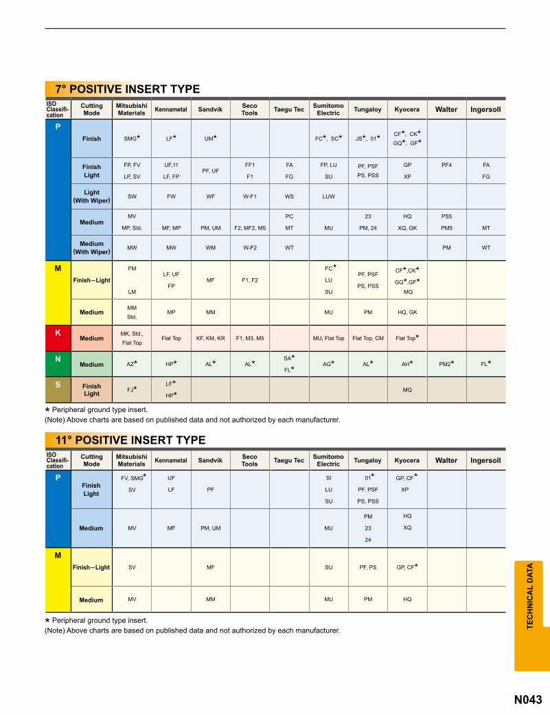
N043
PSMG* LF* UM* FC*, SC* JS*, 01* CF*, CK*
GQ*, GF*
FP, FV
LP, SV
UF,11
LF, FPPF, UF
FF1
F1
FA
FG
FP, LU
SU
PF, PSFPS, PSS
GP
XP
PF4 FA
FG
SW FW WF W-F1 WS LUW
MF, MP PM, UM F2, MF2, M5
PC
MT MU
23
PM, 24
HQ
XQ, GK
PS5
PM5 MT
MW MW WM W-F2 WT PM WT
M FM
LM
LF, UF
FPMF F1, F2
FC
LU
SU
PF, PSF
PS, PSS
CF*,CK*
GQ*,GF* MQ
MP MM MU PM HQ, GK
KKF, KM, KR F1, M3, M5
NAZ* HP* AL* AL*
SA*FL*
AG* AL* AH* PM2* FL*
SFJ*
LF*HP*
MQ
P FV, SMG
SV
UF
LF PF
SI
LU
SU
01
PF, PSF
PS, PSS
GP, CF
XP
MV MF PM, UM MU
PM
23
24
HQ
XQ
MSV MF SU PF, PS GP, CF*
MV MM MU PM HQ
*
* **
TEC
HN
ICA
L D
ATA
* Peripheral ground type insert.
* Peripheral ground type insert.
(Note) Above charts are based on published data and not authorized by each manufacturer.
(Note) Above charts are based on published data and not authorized by each manufacturer.
7° POSITIVE INSERT TYPE
11° POSITIVE INSERT TYPE
CuttingMode
CuttingMode
Finish
FinishLight
Light(With Wiper)
Medium
Medium(With Wiper)
Finish─Light
Medium
Medium
Medium
FinishLight
FinishLight
Medium
Finish─Light
Medium
ISOClassifi-cation
ISOClassifi-cation
MV
MP, Std.
MMStd.
MU, Flat TopFlat Top Flat Top, CM Flat Top*MK, Std., Flat Top
MitsubishiMaterials Kennametal Sandvik Seco
Tools Taegu Tec SumitomoElectric Tungaloy Kyocera Walter Ingersoll
MitsubishiMaterials Kennametal Sandvik Seco
Tools Taegu Tec SumitomoElectric Tungaloy Kyocera Walter Ingersoll