Embed Size (px)
Citation preview
GEKKOPortable Ultrasonic Flaw Detector for Phased Array, TOFDand Conventional Probes

B-Scan Imaging
Sector Scan and Linear ScanPhased array probes consist of multiple piezoelectric elements, which can be excited one by one or time-delayed. The sound fi elds of several elements which form a so-called virtual probe are superimposed. Thus, the resulting sound fi eld can be electronically moved (linear scan) or swivelled (sector scan). Both longitudinal and transverse waves, but also surface and creeping waves can be generated. Electronic focusing of the sound fi eld in certain depths or depth ranges permits the indication of B-scans (cross-sectional views per-pendicular to the surface) with high resolution.
Sector scan generated by swivelling the sound fi eld within an angular range of -45° to +45°
Linear scan generated by electronically moving the sound fi eld within an array probe
In the example given above a sector scan and a linear scan of a row of side drilled holes in an ASTM reference block are shown. The GEKKO also features a calibration function that adjusts the echo amplitudes for all sound paths and angles to the same value. The lateral spatial resolution equals the diameter of the focused sound fi eld. Sector and linear scans are the traditional B-scan techniques. With the new TFM method even higher resolutions can be achieved:
The Total Focusing Method is a unique feature and comparable to sampling phased array techniques. It integrates all interactions between all array elements and all pixels in a defi ned inspection area. Thus, it generates B-scans with an extremely high spatial resolution of 1 (!) wavelength if a phased array probe with 64 elements is used. Up to 25 frames per second can be achieved, thus providing real-time imaging.
Refl ector sizes are measured with the aid of cursors. The example shows the TFM-B-scan of a row of 1.5 mm diameter side-drilled holes. As a result the correct hole diameter of 1.5 mm is shown.
Total Focusing Method (TFM)
Phased array calibration block, according to ASTM E 2491
2
TFM-B-scan Refl ector sizing with cursorsDefi nition of a test area as x-y-grid Test block with side-drilled holes
Inspection setup, test object with flat bottom bores
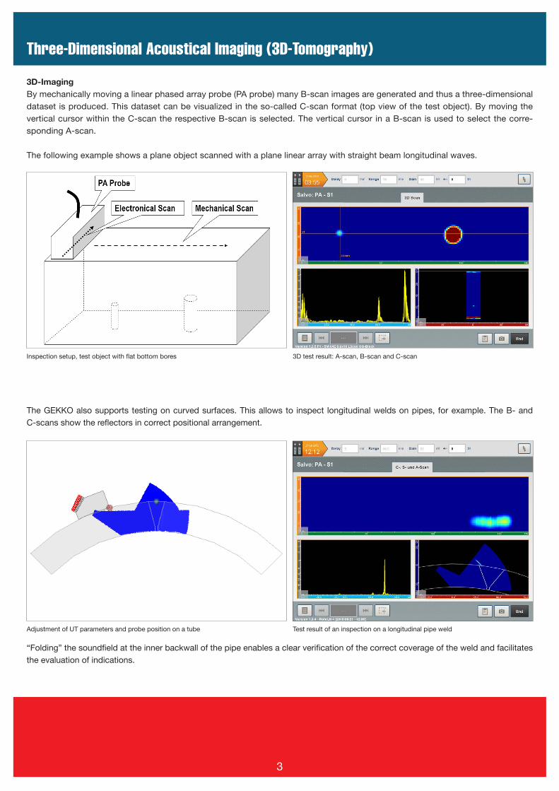
The GEKKO also supports testing on curved surfaces. This allows to inspect longitudinal welds on pipes, for example. The B- and C-scans show the reflectors in correct positional arrangement.
3D-Imaging By mechanically moving a linear phased array probe (PA probe) many B-scan images are generated and thus a three-dimensional dataset is produced. This dataset can be visualized in the so-called C-scan format (top view of the test object). By moving the vertical cursor within the C-scan the respective B-scan is selected. The vertical cursor in a B-scan is used to select the corre-sponding A-scan.
The following example shows a plane object scanned with a plane linear array with straight beam longitudinal waves.
Three-Dimensional Acoustical Imaging (3D-Tomography)
3D test result: A-scan, B-scan and C-scan
Adjustment of UT parameters and probe position on a tube Test result of an inspection on a longitudinal pipe weld
“Folding” the soundfield at the inner backwall of the pipe enables a clear verification of the correct coverage of the weld and facilitates the evaluation of indications.
3
Menus
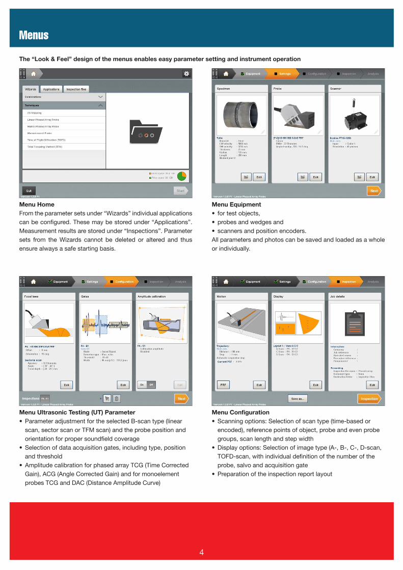
The “Look & Feel” design of the menus enables easy parameter setting and instrument operation
Menu HomeFrom the parameter sets under “Wizards” individual applications can be configured. These may be stored under “Applications”. Measurement results are stored under “Inspections”. Parameter sets from the Wizards cannot be deleted or altered and thus ensure always a safe starting basis.
Menu Ultrasonic Testing (UT) Parameter• Parameter adjustment for the selected B-scan type (linear
scan, sector scan or TFM scan) and the probe position and orientation for proper soundfield coverage
• Selection of data acquisition gates, including type, position and threshold
• Amplitude calibration for phased array TCG (Time Corrected Gain), ACG (Angle Corrected Gain) and for monoelement probes TCG and DAC (Distance Amplitude Curve)
Menu Equipment • for test objects, • probes and wedges and• scanners and position encoders.All parameters and photos can be saved and loaded as a whole or individually.
Menu Configuration• Scanning options: Selection of scan type (time-based or
encoded), reference points of object, probe and even probe groups, scan length and step width
• Display options: Selection of image type (A-, B-, C-, D-scan, TOFD-scan, with individual definition of the number of the probe, salvo and acquisition gate
• Preparation of the inspection report layout
4
Tools and Wizards
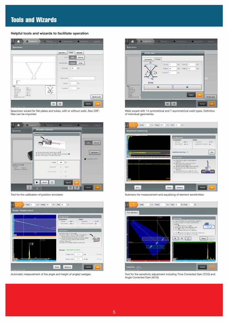
Helpful tools and wizards to facilitate operation
Specimen wizard for flat plates and tubes, with or without weld. Also DXF-files can be imported.
Weld wizard with 14 symmetrical and 7 asymmetrical weld types. Definition of individual geometries.
Tool for the calibration of position encoders Submenu for measurement and equalizing of element sensitivities
Automatic measurement of the angle and height of angled wedges Tool for the sensitivity adjustment including Time Corrected Gain (TCG) and Angle Corrected Gain (ACG)
5
Combinations
Double gimbal-mounted probe holders
For Phased Array probes with wedge type 1814.13x For TOFD probes with wedge type 6148.xxx
Weld Testing with 2 x Phased Array and TOFD
For phased array probeswith wedge type 1814.13x
For TOFD probeswith wedge type 6148.xxx
Combination of Several Encoders: Area Scanning with 2D-Mapping
The GEKKO supports meandrical area scanning!If test specimens are larger than the scan width of a phased ar-ray probe, the area can be scanned meandrically. The individual C-scan tracks are then composed to a complete C-scan.• The mechanical scan can be done either with a motorized
scanning system or with an x-y-scanner for manual testing.• 2D-scanning of areas is useful for volume testing and for cor-
rosion mapping. A C-scan presents inclusions in the volume and a D-scan informs about residual wall thicknesses in the case of corrosion mapping.
• The GEKKO supports up to three position encoders.
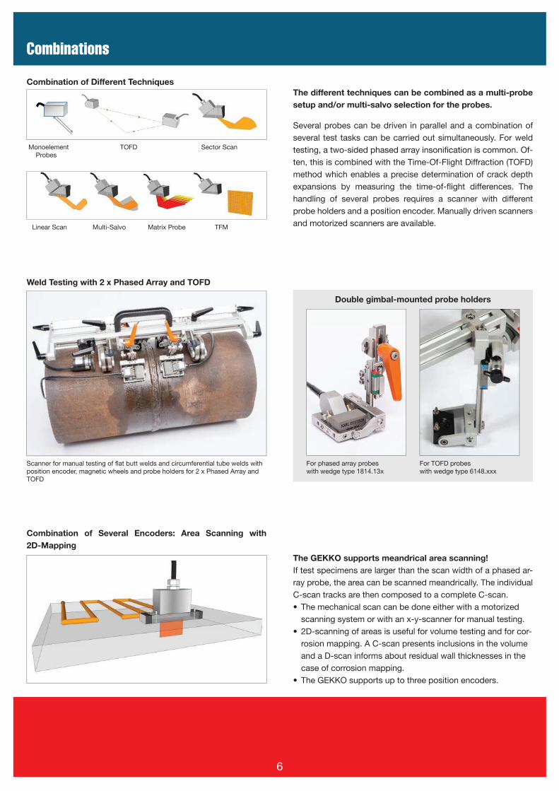
Monoelement TOFD Sector Scan Probes
Linear Scan Multi-Salvo Matrix Probe TFM
Combination of Different TechniquesThe different techniques can be combined as a multi-probe setup and/or multi-salvo selection for the probes.
Several probes can be driven in parallel and a combination of several test tasks can be carried out simultaneously. For weld testing, a two-sided phased array insonifi cation is common. Of-ten, this is combined with the Time-Of-Flight Diffraction (TOFD) method which enables a precise determination of crack depth expansions by measuring the time-of-fl ight differences. The handling of several probes requires a scanner with different probe holders and a position encoder. Manually driven scanners and motorized scanners are available.
6
Scanner for manual testing of fl at butt welds and circumferential tube welds with position encoder, magnetic wheels and probe holders for 2 x Phased Array and TOFD
Matrix Arrays, Report Generation
After set-up of the parameters the test proce-dure can start and the results can be export-ed. The following items are selectable for the report (additional entry fi elds can be defi ned):
• Date and place of the inspection• Inspector• Object parameters• Probe parameters• Scanner parameters• UT parameter settings• Gate parameters• TCG and sensitivity settings
After analysis of the inspection data, a com-plete inspection report is generated with a table of indications and optionally with im-ages of the defect indications. Parameters without a test result, or only with an exam-ple on how a test result may be represent-ed, can be used as an instruction for testing. The test procedure and inspection report are exported as a PDF and can be stored on a memory stick.
“GekkoView” software for an external PC:The included software “GekkoView” permits exporting of the inspection result to an ex-ternal computer. This enables the operator to continue the inspection work while anoth-er staff member takes care of further data analysis and report generation.
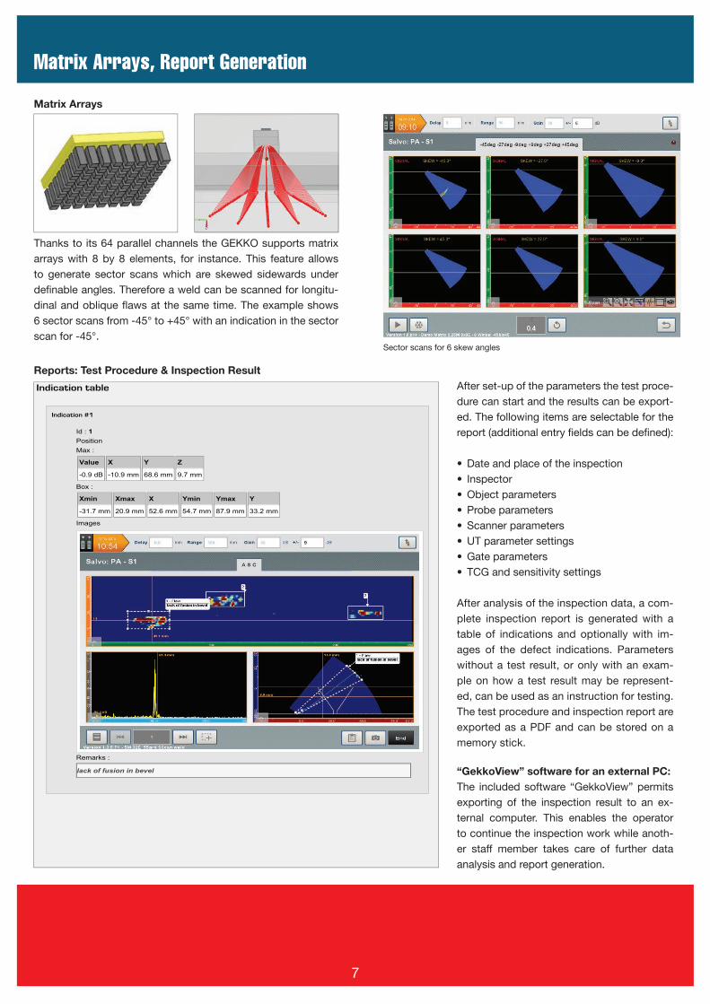
Matrix Arrays
Thanks to its 64 parallel channels the GEKKO supports matrix arrays with 8 by 8 elements, for instance. This feature allows to generate sector scans which are skewed sidewards under defi nable angles. Therefore a weld can be scanned for longitu-dinal and oblique fl aws at the same time. The example shows 6 sector scans from -45° to +45° with an indication in the sector scan for -45°.
Reports: Test Procedure & Inspection Result
Sector scans for 6 skew angles
7
KARL DEUTSCH Pruef- und Messgeraetebau GmbH + Co KG
Otto-Hausmann-Ring 101 · 42115 Wuppertal · Germany
Phone (+49-202) 7192-0 · Fax (+49-202) 71 49 32
[email protected] · www.karldeutsch.de
DIN EN ISO9001
certif ied
Technical Data
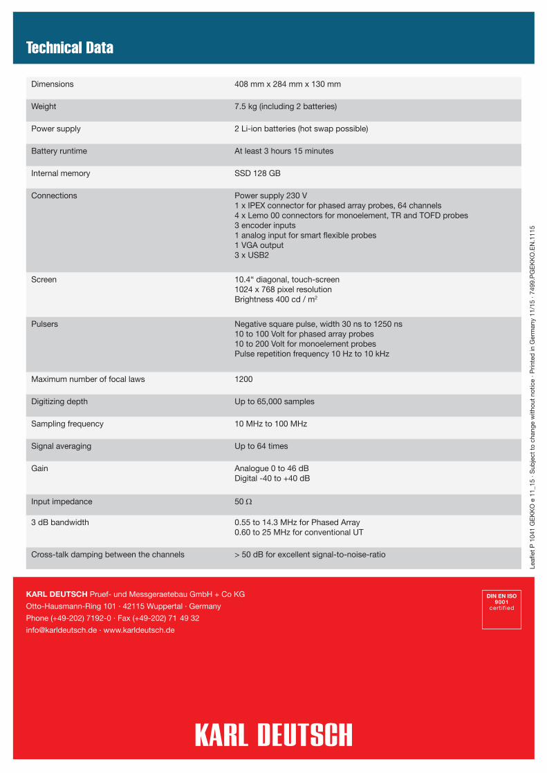
Dimensions 408 mm x 284 mm x 130 mm
Weight 7.5 kg (including 2 batteries)
Power supply 2 Li-ion batteries (hot swap possible)
Battery runtime At least 3 hours 15 minutes
Internal memory SSD 128 GB
Connections Power supply 230 V1 x IPEX connector for phased array probes, 64 channels4 x Lemo 00 connectors for monoelement, TR and TOFD probes3 encoder inputs1 analog input for smart flexible probes1 VGA output3 x USB2
Screen 10.4“ diagonal, touch-screen1024 x 768 pixel resolutionBrightness 400 cd / m2
Pulsers Negative square pulse, width 30 ns to 1250 ns10 to 100 Volt for phased array probes10 to 200 Volt for monoelement probesPulse repetition frequency 10 Hz to 10 kHz
Maximum number of focal laws 1200
Digitizing depth Up to 65,000 samples
Sampling frequency 10 MHz to 100 MHz
Signal averaging Up to 64 times
Gain Analogue 0 to 46 dBDigital -40 to +40 dB
Input impedance 50 Ω
3 dB bandwidth 0.55 to 14.3 MHz for Phased Array0.60 to 25 MHz for conventional UT
Cross-talk damping between the channels > 50 dB for excellent signal-to-noise-ratio
Leafl
et P
104
1 G
EK
KO
e 1
1_15
· S
ubje
ct t
o ch
ange
with
out
notic
e · P
rinte
d in
Ger
man
y 11
/15
· 749
9.P
GE
KK
O.E
N.1
115


![Fatigue Flaw NDE Reference Standard Development - Phase … · ultrasonic testing (UT), ... (EMAT), phased array ultrasound, and long-range guided wave (LRGW)]; electromagnetic methods](https://img.dokumen.tips/doc/110x75/5ac244ba7f8b9ae45b8e57f7/fatigue-flaw-nde-reference-standard-development-phase-testing-ut-emat.jpg)