Embed Size (px)
Citation preview
Gear Type Flow Meter
VC
®
2 KRACHT CORP. · 6552 Weatherfield Court · Maumee, OH 43537 · USA · P +1 419 874 1000 · F +1 419 874 1006 · [email protected] · www.krachtcorp.com
Gear Type Flow Meter VC
3KRACHT CORP. · 6552 Weatherfield Court · Maumee, OH 43537 · USA · P +1 419 874 1000 · F +1 419 874 1006 · [email protected] · www.krachtcorp.com
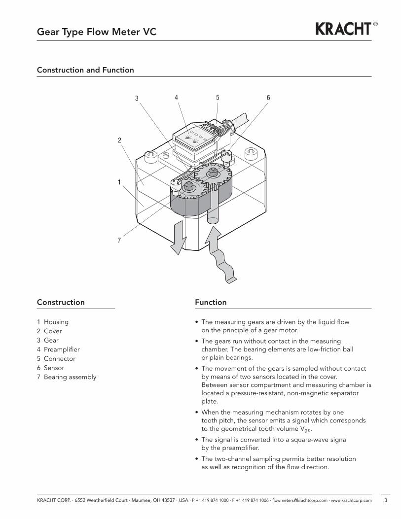
1 Housing2 Cover3 Gear4 Preamplifier5 Connector6 Sensor7 Bearing assembly
• The measuring gears are driven by the liquid flow on the principle of a gear motor.
• The gears run without contact in the measuring chamber. The bearing elements are low-friction ball or plain bearings.
• The movement of the gears is sampled without contactby means of two sensors located in the cover. Between sensor compartment and measuring chamber islocated a pressure-resistant, non-magnetic separatorplate.
• When the measuring mechanism rotates by one tooth pitch, the sensor emits a signal which correspondsto the geometrical tooth volume Vgz .
• The signal is converted into a square-wave signal by the preamplifier.
• The two-channel sampling permits better resolution as well as recognition of the flow direction.
1
2
3 4 6
7
5
FunctionConstruction
Gear Type Flow Meter VC
Construction and Function
4 KRACHT CORP. · 6552 Weatherfield Court · Maumee, OH 43537 · USA · P +1 419 874 1000 · F +1 419 874 1006 · [email protected] · www.krachtcorp.com
Gear Type Flow Meter VC
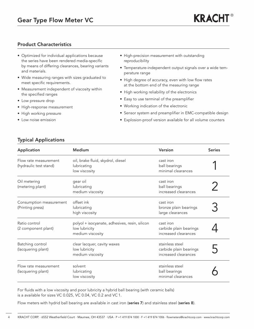
Typical Applications
Application Medium Version Series
Flow rate measurement oil, brake fluid, skydrol, diesel cast iron(hydraulic test stand) lubricating ball bearings
low viscosity minimal clearances1
Oil metering gear oil cast iron(metering plant) lubricating ball bearings
medium viscosity increased clearances2
Consumption measurement offset ink cast iron(Printing press) lubricating bronze plain bearings
high viscosity large clearances3
Ratio control polyol + isocyanate, adhesives, resin, silicon cast iron(2 component plant) low lubricity carbide plain bearings
medium viscosity increased clearances4
Batching control clear lacquer, cavity waxes stainless steel(lacquering plant) low lubricity carbide plain bearings
medium viscosity increased clearances5
Flow rate measurement solvent stainless steel(lacquering plant) lubricating ball bearings
low viscosity minimal clearances6
For fluids with a low viscosity and poor lubricity a hybrid ball bearing (with ceramic balls)is a available for sizes VC 0.025, VC 0.04, VC 0.2 and VC 1.
Flow meters with hydrid ball bearing are available in cast iron (series 7) and stainless steel (series 8).
Product Characteristics
• Optimized for individual applications because the series have been rendered media-specific by means of differing clearances, bearing variantsand materials.
• Wide measuring ranges with sizes graduated tomeet specific requirements.
• Measurement independent of viscosity within the specified ranges
• Low pressure drop
• High-response measurement
• High working pressure
• Low noise emission
• High-precision measurement with outstanding reproducibility
• Temperature-independent output signals over a wide tem-perature range
• High degree of accuracy, even with low flow rates at the bottom end of the measuring range
• High working reliability of the electronics
• Easy to use terminal of the preamplifier
• Working indication of the electronic
• Sensor system and preamplifier in EMC-compatible design
• Explosion-proof version available for all volume counters
5KRACHT CORP. · 6552 Weatherfield Court · Maumee, OH 43537 · USA · P +1 419 874 1000 · F +1 419 874 1006 · [email protected] · www.krachtcorp.com
Accuracy Characteristics
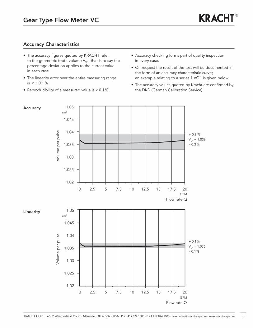
• The accuracy figures quoted by KRACHT refer to the geometric tooth volume Vgz, that is to say the percentage deviation applies to the current value in each case.
• The linearity error over the entire measuring range is < ± 0.1%
• Reproducibility of a measured value is < 0.1%
Accuracy
Linearity
1.05
1.045
1.04
1.035
1.03
1.025
1.02
+ 0.3 %Vgz = 1.036-- 0.3 %
0 2.5 5 7.5 10 12.5 15 17.5 20
1.05
1.045
1.04
1.035
1.03
1.025
1.02
+ 0.1%Vgz = 1.036-- 0.1%
0 2.5 5 7.5 10 12.5 15 17.5 20
• Accuracy checking forms part of quality inspection in every case.
• On request the result of the test will be documented inthe form of an accuracy characteristic curve; an example relating to a series 1 VC 1 is given below.
• The accuracy values quoted by Kracht are confirmed bythe DKD (German Calibration Service).
Volume per pulse
Volume per pulse
Flow rate QGPM
Flow rate QGPM
cm3
cm3
Gear Type Flow Meter VC
6 KRACHT CORP. · 6552 Weatherfield Court · Maumee, OH 43537 · USA · P +1 419 874 1000 · F +1 419 874 1006 · [email protected] · www.krachtcorp.com
Gear Type Flow Meter VC
General Characteristics
Design gear motor
Connection type plate mounting/pipe connection
Mounting position optional
Flow direction optional
Viscosity 1...1.000.000 cSt, (according to series)
Max. pressure drop Dpmax = 16 bar / 230 psi
Working Characteristics
Nominal geom. max. working pressure Peak pressure Sound Resolutionsize tooth- Standard- High pressure Standard- High pressure pressure
volume version version (/79) version version (/79) level
VgZ pmax pmax p̂ p̂ LA Pulse/lcm3 bar / psi bar / psi bar / psi bar / psi dB (A) Pulse/gal.
0.025 0.025 400 / 5800 – 480 / 6960 – < 60 40,000.00151,417.600
0.04 0.04 400 / 5800 – 480 / 6960 – < 60 25,000.0094,636.00
0.1 0.10 400 / 5800 – 480 / 6960 – < 60 10,000.0037,854.00
0.2 0.245 400 / 5800 – 480 / 6960 – < 60 4,081.6315,450.77
0.4 0.40 400 / 5800 – 480 / 6960 – < 70 2,500.009,463.60
1 1.036 400 / 5800 – 480 / 6960 – < 70 965.253,653.90
3 3.000 315 / 4570 400 / 5800 350 / 5080 480 / 6960 < 70 333.331,261.81
5 5.222 315 / 4570 400 / 5800 350 / 5080 480 / 6960 < 72 191.50724.90
12 12.000 400 / 5800 – 480 / 6960 – < 80 83.33315.45
16 16.000 400 / 5800 – 480 / 6960 – < 80 62.50236.59
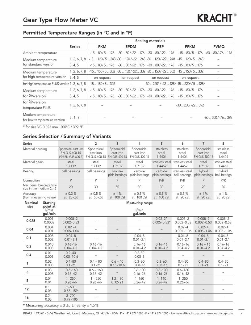
Permitted Temperature Ranges (in °C and in °F)
Sealing materials
Series FKM EPDM FEP FFKM FVMQ
Ambient temperature -15 ... 80 / 5 ... 176 -30 ... 80 / -22 ... 176 -30 ... 80 / -22 ... 176 -15 ... 80 / 5 ... 176 -60 ... 80 / -76 ... 176
Medium temperature 1, 2, 6, 7, 8 -15 ... 120 / 5 ... 248 -30 ... 120 / -22 ... 248 -30 ... 120 / -22 ... 248 -15 ... 120 / 5 ... 248 –for standard version 3, 4, 5 -15 ... 80 / 5 ... 176 -30 ... 80 / -22 ... 176 -30 ... 80 / -22 ... 176 -15 ... 80 / 5 ... 176 –
Medium temperature 1, 2, 6, 7, 8 -15 ... 150 / 5 ... 302 -30 ... 150 / -22 ... 302 -30 ... 150 / -22 ... 302 -15 ... 150 / 5 ... 302 –for high temperature version 3, 4, 5 on request on request on request on request –
for high temperature PLUS version1, 2, 6, 7, 8 -15 ... 150 / 5 ... 302 – -30 ... 220* / -22 ... 428* -15 ... 220* / 5 ... 428* –
Medium temperature 1, 2, 6, 7, 8 -15 ... 80 / 5 ... 176 -30 ... 80 / -22 ... 176 -30 ... 80 / -22 ... 176 -15 ... 80 / 5 ... 176 –
for -version 3, 4, 5 -15 ... 80 / 5 ... 176 -30 ... 80 / -22 ... 176 -30 ... 80 / -22 ... 176 -15 ... 80 / 5 ... 176 –
for -version temperature PLUS
1, 2, 6, 7, 8 – – – -30 ... 200/ -22 ... 392 –
Medium temperaturefor low temperature version
5, 6, 8 – – – – -60 ... 200 / -76 ... 392
* for size VC 0.025 max. 200°C / 392 °F
7KRACHT CORP. · 6552 Weatherfield Court · Maumee, OH 43537 · USA · P +1 419 874 1000 · F +1 419 874 1006 · [email protected] · www.krachtcorp.com
Gear Type Flow Meter VC
Series Selection / Summary of VariantsSeries 1 2 3 4 5 6 7 8
Material housing Spheroidal cast iron Spheroidal Spheroidal Spheroidal stainless stainless Spheroidal stainlessEN-GJS-400-15 cast iron cast iron cast iron steel steel cast iron steel
(/79 EN-GJS-600-3) EN-GJS-400-15 EN-GJS-400-15 EN-GJS-400-15 1.4404 1.4404 EN-GJS-400-15 1.4404Material gears steel steel steel steel stainless steel stainless steel steel stainless steel
1.7139 1.7139 1.7139 1.7139 1.4462 1.4462 1.7139 1.4462Bearing ball bearings ball bearings bronze- carbide carbide stainless steel hybrid hybrid
plain bearings plain bearings plain bearings ball bearings plain bearings ball bearigs
Connection P P P P P/R P/R P P/RMax. perm. foreign particle 20 30 50 30 30 20 20 20size in the medium (μm)
Accuracy ± 0.3 % ± 0.5 % ± 1 % ± 0.5 % ± 0.5 % ± 0.3 % ± 1 % ± 1 %(from measuring value) at � 20 cSt at � 50 cSt at �100 cSt at �100 cSt at �100 cSt at � 20 cSt at � 20 cSt at � 20 cSt
Nominal Starting Measuring rangesize point at
l/min l/mingal./min gal./min
0.025 0.001 0.008-2 – – – 0.02-2* 0.008-2 0.008-2 0.008-20.0003 0.002-0.53 0.005-0.53* 0.002-0.53 0.002-0.53 0.002-0.53
0.04 0.004 0.02 -4 – – – – 0.02-4 0.02-4 0.02-40.001 0.005-1.06 0.005-1.06 0.005-1.06 0.005-1.06
0.1 0.008 0.04-8 – – 0.04-8 – 0.04-8 0.04-8 0.04-80.002 0.01-2.1 0.01-2.1 0.01-2.1 0.01-2.1 0.01-2.1
0.2 0.010 0.16-16 0.16-16 – 0.16-16 0.16-16 0.16-16 0.16 – 16 0.16-160.003 0.04-4.2 0.04-4.2 0.04-4.2 0.04-4.2 0.04-4.2 0.04-4.2 0.04-4.2
0.4 0.010 0.2-40 – – 0.2-30 – – –0.003 0.05-10.6 0.05-8
1 0.020 0.4-80 0.4 – 80 0.6 – 40 0.3-60 0.3-60 0.4-80 0.4-80 0.4-800.005 0.1-21 0.1-21 0.15-10.6 0.08-16 0.08-16 0.1-21 0.1-21 0.1-21
3 0.030 0.6-160 0.6 – 160 – 0.6-100 0.6-100 0.6-160 – –0.008 0.16-42 0.16-42 0.16-26 0.16-26 0.16-42
5 0.040 1 - 250 1 – 250 1.2 – 80 1-160 1-160 1-250 – –0.010 0.26-66 0.26-66 0.32-21 0.26-42 0.26-42 0.26-66
12 0.100 2-600 – – – – – – –0.030 0.53-159
16 0.200 3-700 – – – – – – –0.050 0.79-185
* Measuring accuracy ± 3%; Linearity ± 1.5%
8 KRACHT CORP. · 6552 Weatherfield Court · Maumee, OH 43537 · USA · P +1 419 874 1000 · F +1 419 874 1006 · [email protected] · www.krachtcorp.com
Gear Type Flow Meter VC
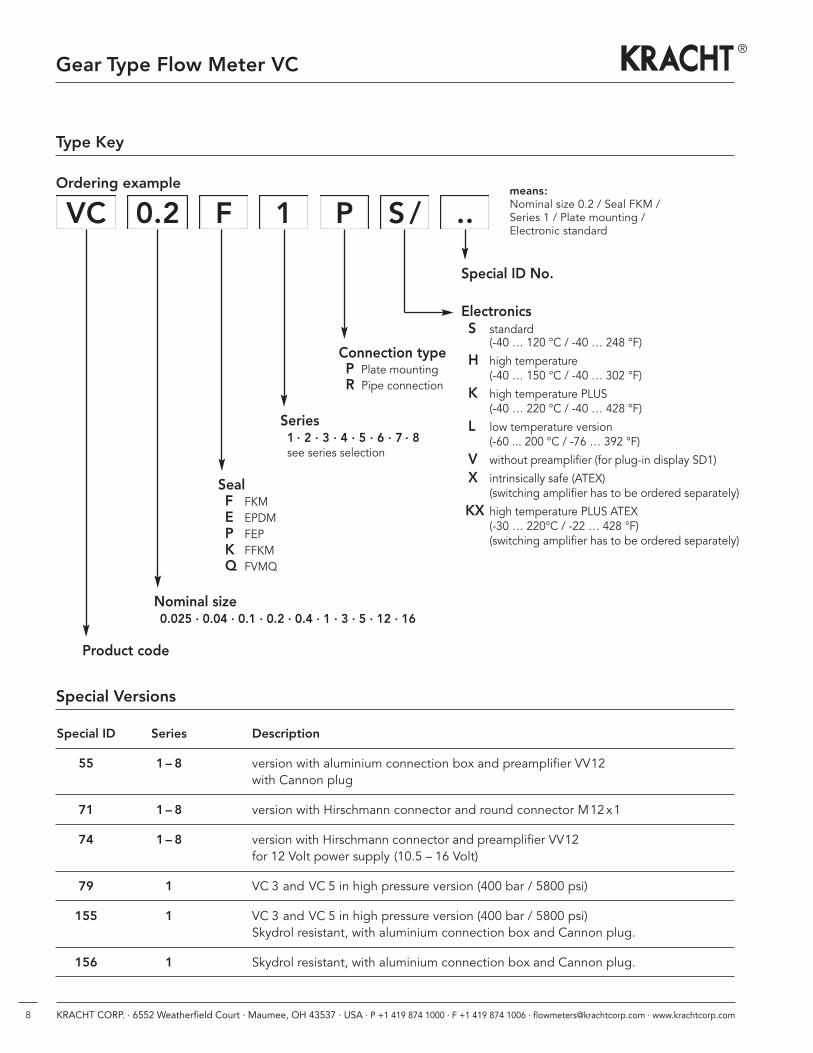
Special Versions
Special ID Series Description
55 1– 8 version with aluminium connection box and preamplifier VV12with Cannon plug
71 1– 8 version with Hirschmann connector and round connector M12x1
74 1– 8 version with Hirschmann connector and preamplifier VV12for 12 Volt power supply (10.5 – 16 Volt)
79 1 VC 3 and VC 5 in high pressure version (400 bar / 5800 psi)
155 1 VC 3 and VC 5 in high pressure version (400 bar / 5800 psi)Skydrol resistant, with aluminium connection box and Cannon plug.
156 1 Skydrol resistant, with aluminium connection box and Cannon plug.
Type Key
Ordering example
VC 0.2 F 1 P S / ..
Special ID No.
ElectronicsS standard
(-40 … 120 °C / -40 … 248 °F)
H high temperature (-40 … 150 °C / -40 … 302 °F)
K high temperature PLUS (-40 … 220 °C / -40 … 428 °F)
L low temperature version (-60 ... 200 °C / -76 … 392 °F)
V without preamplifier (for plug-in display SD1)
X intrinsically safe (ATEX)(switching amplifier has to be ordered separately)
KX high temperature PLUS ATEX (-30 … 220°C / -22 … 428 °F)(switching amplifier has to be ordered separately)
Connection typeP Plate mountingR Pipe connection
Series1 · 2 · 3 · 4 · 5 · 6 · 7 · 8see series selection
Product code
Nominal size0.025 · 0.04 · 0.1 · 0.2 · 0.4 · 1 · 3 · 5 · 12 · 16
SealF FKME EPDMP FEPK FFKMQ FVMQ
means:Nominal size 0.2 / Seal FKM /Series 1 / Plate mounting / Electronic standard
9KRACHT CORP. · 6552 Weatherfield Court · Maumee, OH 43537 · USA · P +1 419 874 1000 · F +1 419 874 1006 · [email protected] · www.krachtcorp.com
Gear Type Flow Meter VC
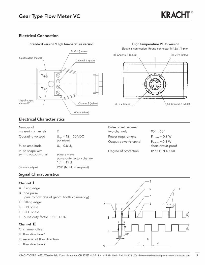
Signal output channel 1
24 Volt (brown)
Channel 1 (green)
Channel 2 (yellow)
0 Volt (white)
Signal outputchannel 2
Signal Characteristics
Channel IA rising edge
B one pulse(corr. to flow rate of geom. tooth volume Vgz )
C falling edge
D ON phase
E OFF phase
F pulse duty factor 1 :1 ± 15 %
Channel IIG channel offset
H flow direction 1
K reversal of flow direction
J flow direction 2
Electrical Characteristics
Number ofmeasuring channels 2
Operating voltage Uop = 12 ... 30 VDCpolarized
Pulse amplitude UA � 0.8 UB
Pulse shape withsymm. output signal square wave
pulse duty factor/channel1:1 ± 15%
Signal output PNP (NPN on request)
Pulse offset betweentwo channels 90° ± 30°
Power requirement Pbmax = 0.9 W
Output power/channel Pa max = 0.3 Wshort-circuit-proof
Degree of protection IP 65 DIN 40050
Electrical Connection
(4) Channel 1 (black) (1) 24 V (brown)
(3) 0 V (blue) (2) Channel 2 (white)
Standard version /High temperature version High temperature PLUS versionElectrical connection (Round connector M12x1/4-pin)
10 KRACHT CORP. · 6552 Weatherfield Court · Maumee, OH 43537 · USA · P +1 419 874 1000 · F +1 419 874 1006 · [email protected] · www.krachtcorp.com
1011
12
78
9
45
6
12
3
1
23
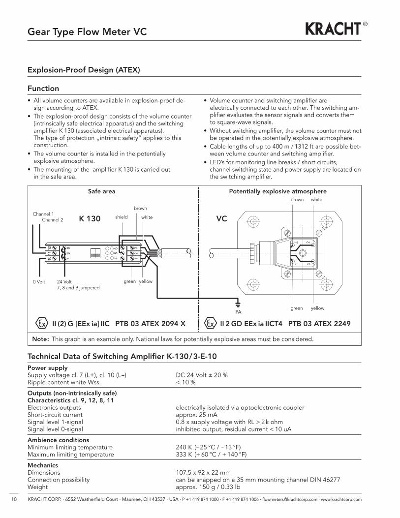
Safe area
K 130
II (2) G [EEx ia] IIC PTB 03 ATEX 2094 X II 2 GD EEx ia IICT4 PTB 03 ATEX 2249
VC
Potentially explosive atmosphere
Channel 2
24 Volt7, 8 and 9 jumpered
shield
green yellow0 Volt
white
brown
yellowgreenPA
brown white
Channel 1
Technical Data of Switching Amplifier K-130/3-E-10Power supplySupply voltage cl. 7 (L+), cl. 10 (L--) DC 24 Volt ± 20 % Ripple content white Wss < 10 %
Outputs (non-intrinsically safe)Characteristics cl. 9, 12, 8, 11Electronics outputs electrically isolated via optoelectronic couplerShort-circuit current approx. 25 mASignal level 1-signal 0.8 x supply voltage with RL > 2 k ohmSignal level 0-signal inhibited output, residual current < 10 uA
Ambience conditionsMinimum limiting temperature 248 K (-- 25 °C / -- 13 °F)Maximum limiting temperature 333 K (+60 °C / +140 °F)
MechanicsDimensions 107.5 x 92 x 22 mmConnection possibility can be snapped on a 35 mm mounting channel DIN 46277Weight approx. 150 g / 0.33 lb
Gear Type Flow Meter VC
Explosion-Proof Design (ATEX)
• All volume counters are available in explosion-proof de-sign according to ATEX.
• The explosion-proof design consists of the volume counter• (intrinsically safe electrical apparatus) and the switchingamplifier K 130 (associated electrical apparatus). The type of protection „intrinsic safety“ applies to thisconstruction.
• The volume counter is installed in the potentially explosive atmosphere.
• The mounting of the amplifier K 130 is carried out in the safe area.
Function• Volume counter and switching amplifier are electrically connected to each other. The switching am- plifier evaluates the sensor signals and converts themto square-wave signals.
• Without switching amplifier, the volume counter must notbe operated in the potentially explosive atmosphere.
• Cable lengths of up to 400 m / 1312 ft are possible bet-ween volume counter and switching amplifier.
• LED’s for monitoring line breaks / short circuits, channel switching state and power supply are located onthe switching amplifier.
Note: This graph is an example only. National laws for potentially explosive areas must be considered.
11KRACHT CORP. · 6552 Weatherfield Court · Maumee, OH 43537 · USA · P +1 419 874 1000 · F +1 419 874 1006 · [email protected] · www.krachtcorp.com
Gear Type Flow Meter VC
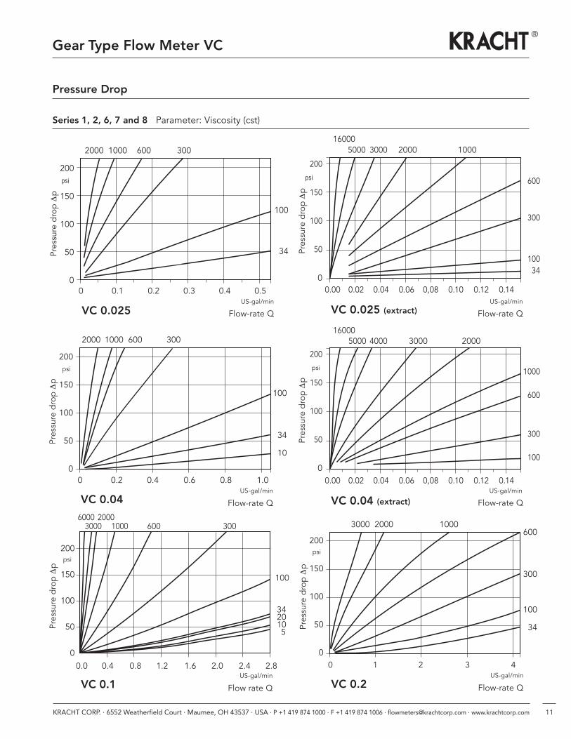
Series 1, 2, 6, 7 and 8 Parameter: Viscosity (cst)
Pressure Drop
Flow rate Q
0.0 0.4 0.8 1.2 1.6 2.0 2.4 2.8
Pressure dropDp
200
150
100
50
0
VC 0.1
psi
US-gal/min
100
3420105
3000 1000 600 3006000 2000
0.00 0.02 0.04 0.06 0,08 0.10 0.12 0.14
0.00 0.02 0.04 0.06 0,08 0.10 0.12 0.14
VC 0.025 (extract)Pressure dropDp
600
300
10034
200
150
100
50
0
5000 3000 2000 1000
psi
Pressure dropDp
200
150
100
50
0
psi
Flow-rate QVC 0.04 (extract)
1000
600
300
100
5000 4000 3000 2000
16000
16000
Flow-rate Q
0 0.2 0.4 0.6 0.8 1.0
Pressure dropDp
100
34
10
200
150
100
50
0
2000 1000 600 300
VC 0.04
psi
US-gal/min US-gal/min
Flow-rate Q
0 1 2 3 4
Pressure dropDp
600
300
100
34
200
150
100
50
0
3000 2000 1000
VC 0.2
psi
US-gal/min
0 0.1 0.2 0.3 0.4 0.5
Flow-rate Q
Pressure dropDp
VC 0.025
100
34
200
150
100
50
0
psi
2000 1000 600 300
US-gal/min
Flow-rate Q
US-gal/min
12 KRACHT CORP. · 6552 Weatherfield Court · Maumee, OH 43537 · USA · P +1 419 874 1000 · F +1 419 874 1006 · [email protected] · www.krachtcorp.com
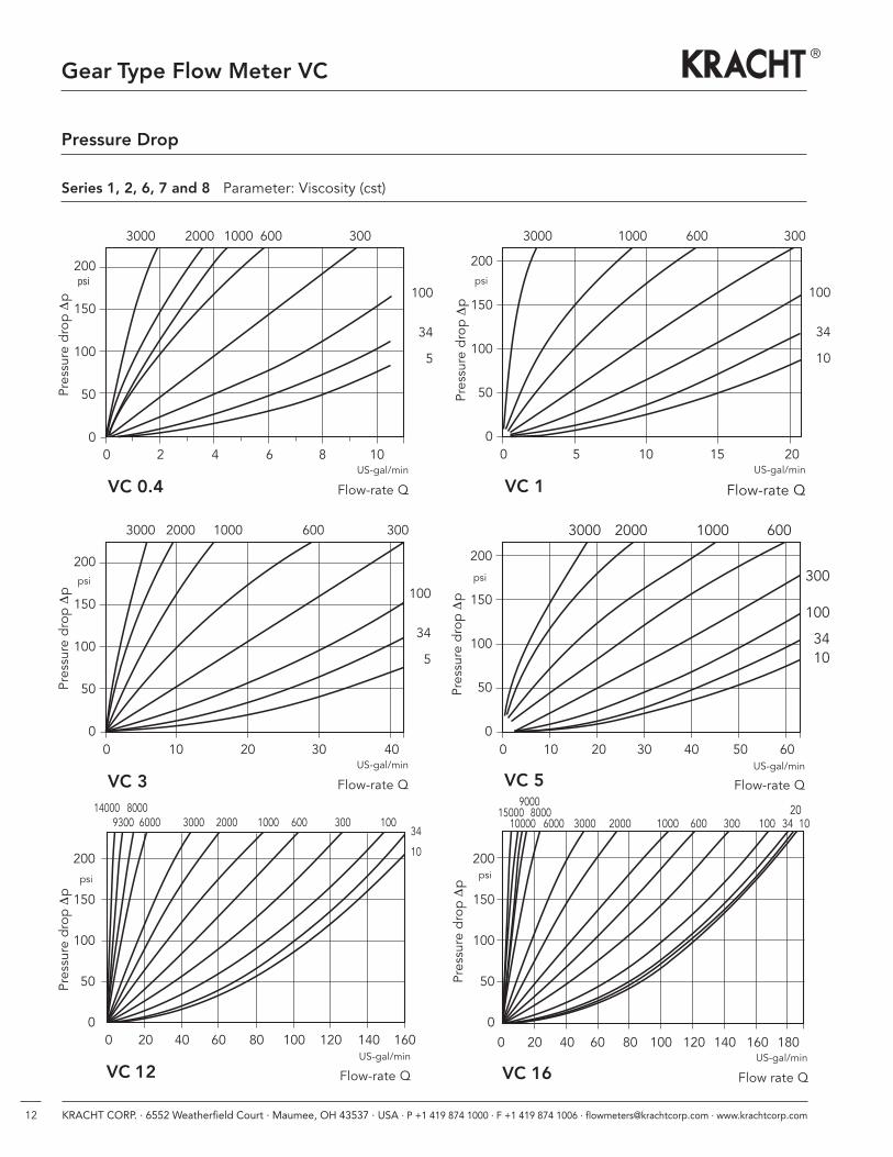
Gear Type Flow Meter VC
Series 1, 2, 6, 7 and 8 Parameter: Viscosity (cst)
Pressure Drop
Flow-rate Q
0 2 4 6 8 10
VC 0.4
Pressure dropDp 100
34
5
200
150
100
50
0
3000 2000 1000 600 300
psi
US-gal/min
Flow-rate Q
0 5 10 15 20
VC 1
Pressure dropDp
100
34
10
200
150
100
50
0
3000 1000 600 300
psi
US-gal/min
Flow-rate Q
0 10 20 30 40
VC 3
Pressure dropDp 100
34
5
200
150
100
50
0
3000 2000 1000 600 300
psi
US-gal/min0 10 20 30 40 50 60
Flow-rate Q
Pressure dropDp
VC 5
300
100
3410
200
150
100
50
0
psi
3000 2000 1000 600
US-gal/min
Flow-rate Q
0 20 40 60 80 100 120 140 160
Pressure dropDp
34
10200
150
100
50
0
200
150
100
50
0
VC 12
psi
US-gal/min
Flow rate Q
0 20 40 60 80 100 120 140 160 180
VC 16
Pressure drop Dp 300
100
345
10000 6000 3000 2000 1000 600 300 100 34 10
psi
US-gal/min
80009000
20150009300 6000 3000 2000 1000 600 300 100
800014000
13KRACHT CORP. · 6552 Weatherfield Court · Maumee, OH 43537 · USA · P +1 419 874 1000 · F +1 419 874 1006 · [email protected] · www.krachtcorp.com
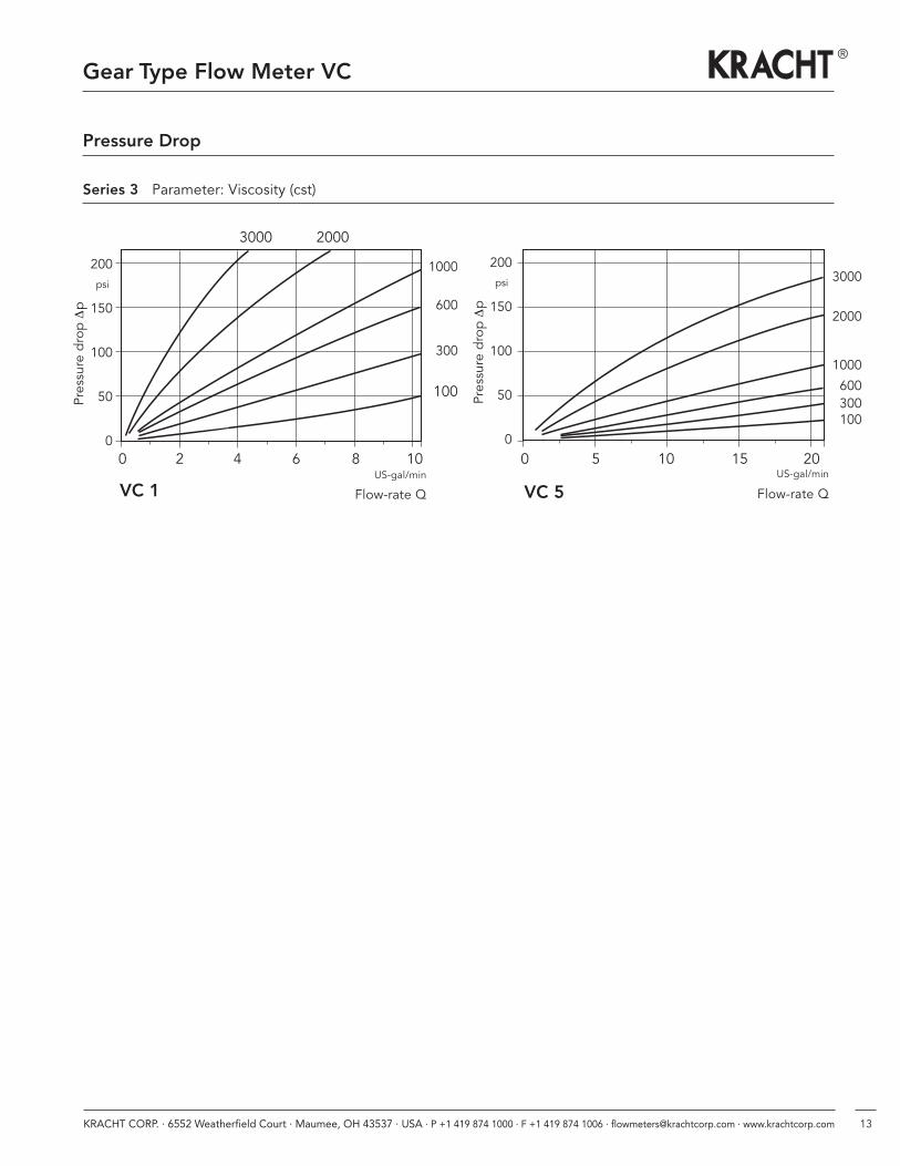
Gear Type Flow Meter VC
Pressure Drop
Series 3 Parameter: Viscosity (cst)
Flow-rate Q
0 2 4 6 8 10
Pressure dropDp
1000
600
300
100
200
150
100
50
0
3000 2000
VC 1 Flow-rate Q
0 5 10 15 20
VC 5Pressure dropDp
3000
2000
1000
600300100
psi
200
150
100
50
0
psi
US-gal/minUS-gal/min
14 KRACHT CORP. · 6552 Weatherfield Court · Maumee, OH 43537 · USA · P +1 419 874 1000 · F +1 419 874 1006 · [email protected] · www.krachtcorp.com
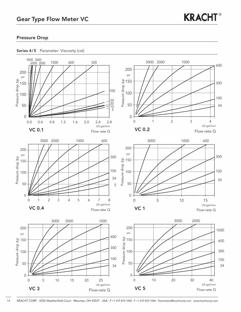
Gear Type Flow Meter VC
Pressure Drop
Flow rate Q
0.0 0.4 0.8 1.2 1.6 2.0 2.4 2.8
Pressure dropDp
6000 2000 1000 600 300
VC 0.1US-gal/min
9000 3000
Series 4/5 Parameter: Viscosity (cst)
Flow-rate Q
0 1 2 3 4Pressure dropDp
600
300
100
34
200
150
100
50
0
3000 2000 1000
VC 0.2
0 5 10 15 20 25
Flow-rate Q
Flow-rate Q
0 5 10 15
Pressure dropDp
VC 1
VC 3
Pressure dropDp
600
300
100
34
300
100
34
200
150
100
50
0
psi
psi200
150
100
50
0
psi
200
150
100
50
0
3000 2000 1000
3000 1000 600
psi
US-gal/min
US-gal/min
Flow-rate Q
0 1 2 3 4 5 6 7 8
Pressure dropDp 300
100
34
5
200
150
100
50
0
3000 2000 1000 600
VC 0.4
psi
US-gal/min
US-gal/min
0 10 20 30 40
Flow-rate Q
Pressure dropDp
VC 5
1000
600
300
100
34
200
150
100
50
0
psi
3000 2000
US-gal/min
100
3420105
15KRACHT CORP. · 6552 Weatherfield Court · Maumee, OH 43537 · USA · P +1 419 874 1000 · F +1 419 874 1006 · [email protected] · www.krachtcorp.com
Gear Type Flow Meter VC
H
S
F
P
G
72 mm / 2.83 inch
J
C
O-Ring
N
M
G
17 mm / 0.67 inch
34 mm / 1.34 inch
N
K
L
P
ML D
K
A
Tightening torque MA
Connection dimensions
Dimensions
Version Sand Version X
Version H
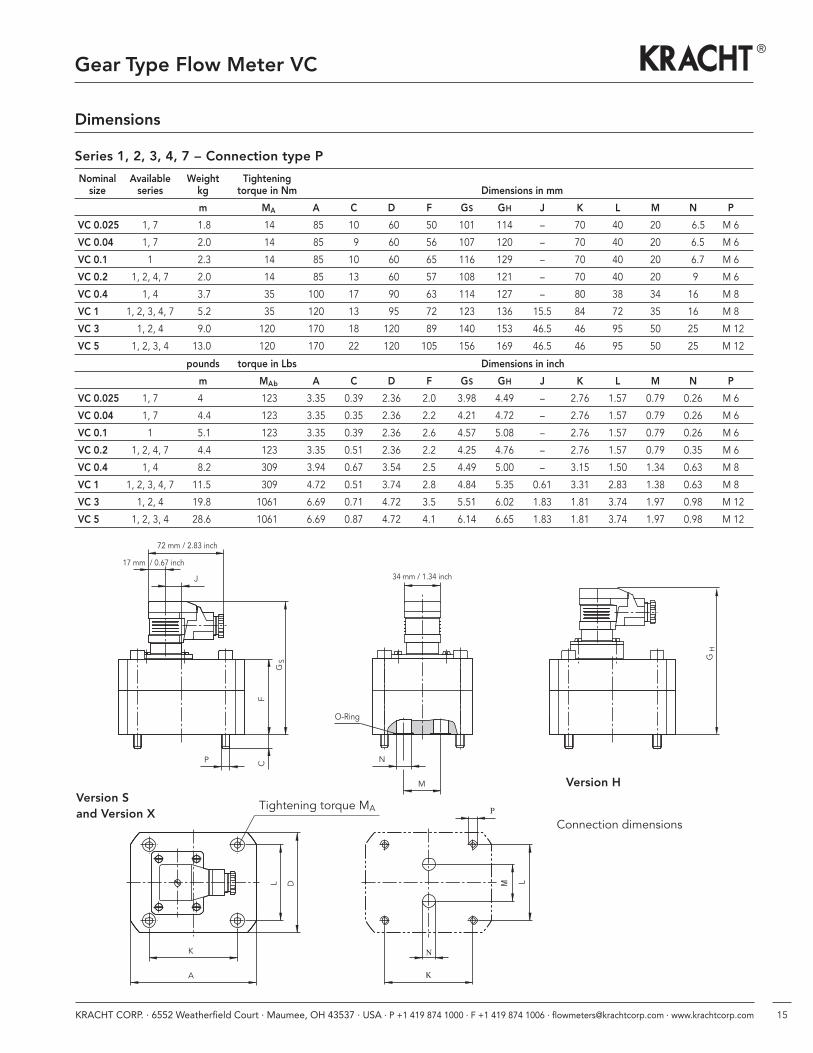
Series 1, 2, 3, 4, 7 – Connection type P
Nominal Available Weight Tighteningsize series kg torque in Nm Dimensions in mm
m MA A C D F GS GH J K L M N P
VC 0.025 1, 7 1.8 14 85 10 60 50 101 114 – 70 40 20 6.5 M 6
VC 0.04 1, 7 2.0 14 85 9 60 56 107 120 – 70 40 20 6.5 M 6
VC 0.1 1 2.3 14 85 10 60 65 116 129 – 70 40 20 6.7 M 6
VC 0.2 1, 2, 4, 7 2.0 14 85 13 60 57 108 121 – 70 40 20 9 M 6
VC 0.4 1, 4 3.7 35 100 17 90 63 114 127 – 80 38 34 16 M 8
VC 1 1, 2, 3, 4, 7 5.2 35 120 13 95 72 123 136 15.5 84 72 35 16 M 8
VC 3 1, 2, 4 9.0 120 170 18 120 89 140 153 46.5 46 95 50 25 M 12
VC 5 1, 2, 3, 4 13.0 120 170 22 120 105 156 169 46.5 46 95 50 25 M 12
pounds torque in Lbs Dimensions in inch
m MAb A C D F GS GH J K L M N P
VC 0.025 1, 7 4 123 3.35 0.39 2.36 2.0 3.98 4.49 – 2.76 1.57 0.79 0.26 M 6
VC 0.04 1, 7 4.4 123 3.35 0.35 2.36 2.2 4.21 4.72 – 2.76 1.57 0.79 0.26 M 6
VC 0.1 1 5.1 123 3.35 0.39 2.36 2.6 4.57 5.08 – 2.76 1.57 0.79 0.26 M 6
VC 0.2 1, 2, 4, 7 4.4 123 3.35 0.51 2.36 2.2 4.25 4.76 – 2.76 1.57 0.79 0.35 M 6
VC 0.4 1, 4 8.2 309 3.94 0.67 3.54 2.5 4.49 5.00 – 3.15 1.50 1.34 0.63 M 8
VC 1 1, 2, 3, 4, 7 11.5 309 4.72 0.51 3.74 2.8 4.84 5.35 0.61 3.31 2.83 1.38 0.63 M 8
VC 3 1, 2, 4 19.8 1061 6.69 0.71 4.72 3.5 5.51 6.02 1.83 1.81 3.74 1.97 0.98 M 12
VC 5 1, 2, 3, 4 28.6 1061 6.69 0.87 4.72 4.1 6.14 6.65 1.83 1.81 3.74 1.97 0.98 M 12
16 KRACHT CORP. · 6552 Weatherfield Court · Maumee, OH 43537 · USA · P +1 419 874 1000 · F +1 419 874 1006 · [email protected] · www.krachtcorp.com
Gear Type Flow Meter VC
Dimensions
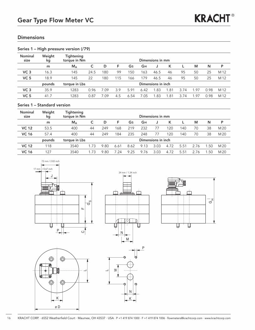
Series 1 – Standard version
Series 1 – High pressure version (/79)
P
C
KN
ML
HG
MN
ø D
K
L
P
F SG
J
72 mm / 2.83 inch
17 mm / 0.67 inch34 mm / 1.34 inch
Nominal Weight Tighteningsize kg torque in Nm Dimensions in mm
m MA C D F GS GH J K L M N P
VC 3 16.3 145 24.5 180 99 150 163 46.5 46 95 50 25 M12
VC 5 18.9 145 22.0 180 115 166 179 46.5 46 95 50 25 M12
pounds torque in Lbs Dimensions in inch
VC 3 35.9 1283 0.96 7.09 3.9 5.91 6.42 1.83 1.81 3.74 1.97 0.98 M12
VC 5 41.7 1283 0.87 7.09 4.5 6.54 7.05 1.83 1.81 3.74 1.97 0.98 M12
Nominal Weight Tighteningsize kg torque in Nm Dimensions in mm
m MA C D F GS GH J K L M N P
VC 12 53.5 400 44 249 168 219 232 77 120 140 70 38 M20
VC 16 57.4 400 44 249 184 235 248 77 120 140 70 38 M20
pounds torque in Lbs Dimensions in inch
VC 12 118 3540 1.73 9.80 6.61 8.62 9.13 3.03 4.72 5.51 2.76 1.50 M20
VC 16 127 3540 1.73 9.80 7.24 9.25 9.76 3.03 4.72 5.51 2.76 1.50 M20
17KRACHT CORP. · 6552 Weatherfield Court · Maumee, OH 43537 · USA · P +1 419 874 1000 · F +1 419 874 1006 · [email protected] · www.krachtcorp.com
Gear Type Flow Meter VC
R
X
X
E
FB
ø A
ø Aae
bC
f G
P
KN
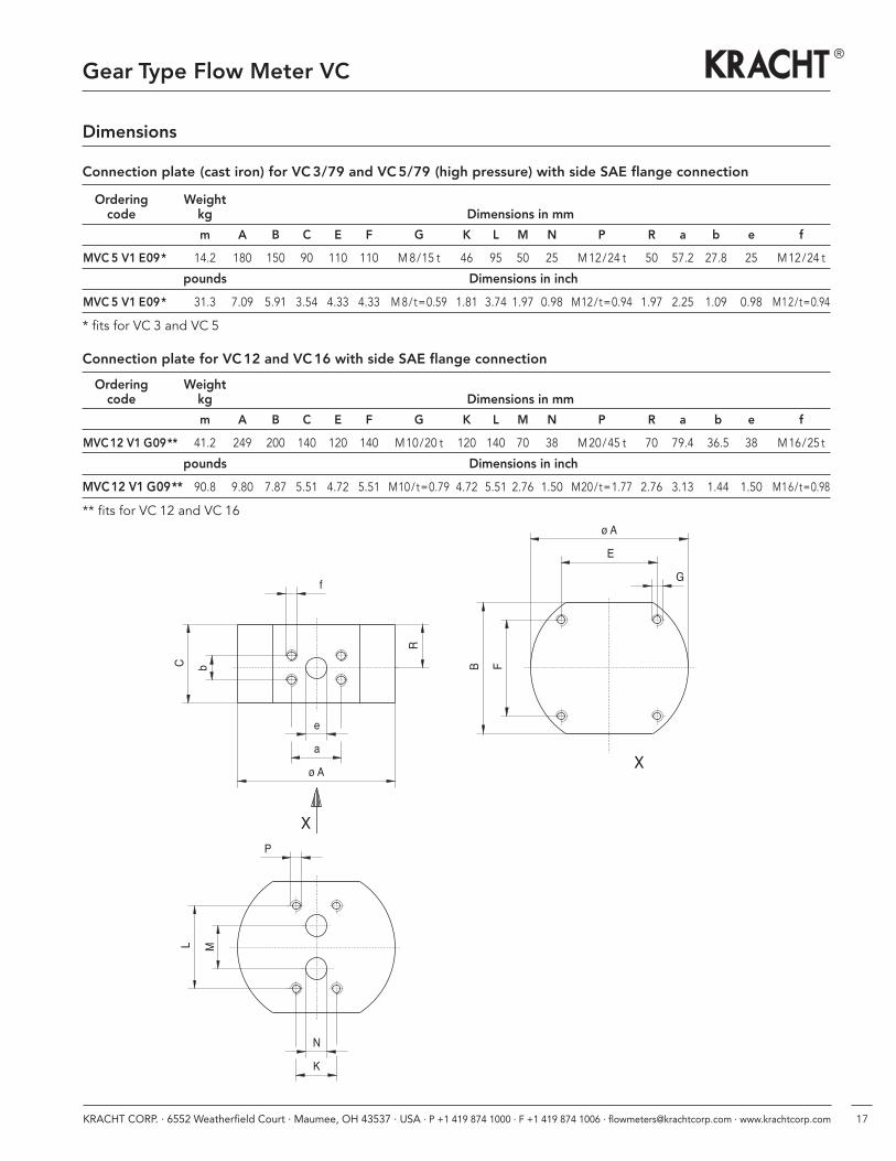
MLConnection plate (cast iron) for VC3/79 and VC5/79 (high pressure) with side SAE flange connection
Ordering Weightcode kg Dimensions in mm
m A B C E F G K L M N P R a b e f
MVC 5 V1 E09* 14.2 180 150 90 110 110 M8/15 t 46 95 50 25 M12/24 t 50 57.2 27.8 25 M12/24 t
pounds Dimensions in inch
MVC 5 V1 E09* 31.3 7.09 5.91 3.54 4.33 4.33 M8/t=0.59 1.81 3.74 1.97 0.98 M12/t=0.94 1.97 2.25 1.09 0.98 M12/t=0.94
* fits for VC 3 and VC 5
Connection plate for VC12 and VC16 with side SAE flange connection
Ordering Weightcode kg Dimensions in mm
m A B C E F G K L M N P R a b e f
MVC12 V1 G09** 41.2 249 200 140 120 140 M10/20 t 120 140 70 38 M20/45 t 70 79.4 36.5 38 M16/25 t
pounds Dimensions in inch
MVC12 V1 G09** 90.8 9.80 7.87 5.51 4.72 5.51 M10/t=0.79 4.72 5.51 2.76 1.50 M20/t=1.77 2.76 3.13 1.44 1.50 M16/t=0.98
** fits for VC 12 and VC 16
Dimensions
18 KRACHT CORP. · 6552 Weatherfield Court · Maumee, OH 43537 · USA · P +1 419 874 1000 · F +1 419 874 1006 · [email protected] · www.krachtcorp.com
Gear Type Flow Meter VC
H
S GO-Ring
J
F
G
C
Ø D Ø N
M
72 mm / 2.83 inch
17 mm / 0.67 inch 34 mm / 1.34 inch
P
LM
Ø N
K
K
L
Connection dimensions
Version Sand Version X
Version H
Tightening torque MA
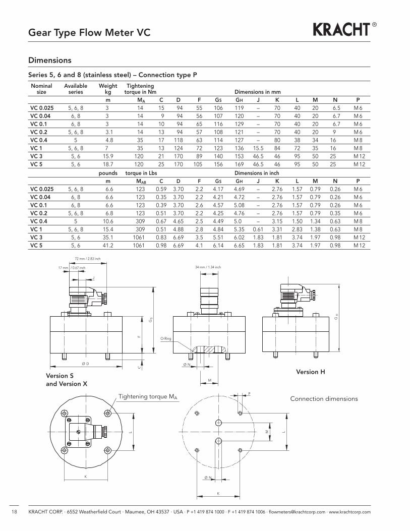
Series 5, 6 and 8 (stainless steel) – Connection type P
Dimensions
Nominal Available Weight Tighteningsize series kg torque in Nm Dimensions in mm
m MA C D F GS GH J K L M N PVC 0.025 5, 6, 8 3.0 140 15 94 55 106 119 – 70 40 20 6.5 M6VC 0.04 6, 8 3.0 140 9 94 56 107 120 – 70 40 20 6.7 M6VC 0.1 6, 8 3.0 140 10 94 65 116 129 – 70 40 20 6.7 M6VC 0.2 5, 6, 8 3.1 140 13 94 57 108 121 – 70 40 20 9.0 M6VC 0.4 5 4.8 350 17 118 63 114 127 – 80 38 34 16,0 M8VC 1 5, 6, 8 7.0 350 13 124 72 123 136 15.5 84 72 35 16.0 M8VC 3 5, 6 15.9 1200 21 170 89 140 153 46.5 46 95 50 25.0 M12VC 5 5, 6 18.7 1200 25 170 1050 156 169 46.5 46 95 50 25.0 M12
pounds torque in Lbs Dimensions in inchm MAB C D F GS GH J K L M N P
VC 0.025 5, 6, 8 6.6 123 0.59 3.70 2.2 4.17 4.69 – 2.76 1.57 0.79 0.26 M6VC 0.04 6, 8 6.6 123 0.35 3.70 2.2 4.21 4.72 – 2.76 1.57 0.79 0.26 M6VC 0.1 6, 8 6.6 123 0.39 3.70 2.6 4.57 5.08 – 2.76 1.57 0.79 0.26 M6VC 0.2 5, 6, 8 6.8 123 0.51 3.70 2.2 4.25 4.76 – 2.76 1.57 0.79 0.35 M6VC 0.4 5 10.6 309 0.67 4.65 2.5 4.49 5.00 – 3.15 1.50 1.34 0.63 M8VC 1 5, 6, 8 15.4 309 0.51 4.88 2.8 4.84 5.35 0.61 3.31 2.83 1.38 0.63 M8VC 3 5, 6 35.1 10610 0.83 6.69 3.5 5.51 6.02 1.83 1.81 3.74 1.97 0.98 M12VC 5 5, 6 41.2 10610 0.98 6.69 4.1 6.14 6.65 1.83 1.81 3.74 1.97 0.98 M12
19KRACHT CORP. · 6552 Weatherfield Court · Maumee, OH 43537 · USA · P +1 419 874 1000 · F +1 419 874 1006 · [email protected] · www.krachtcorp.com
Gear Type Flow Meter VC
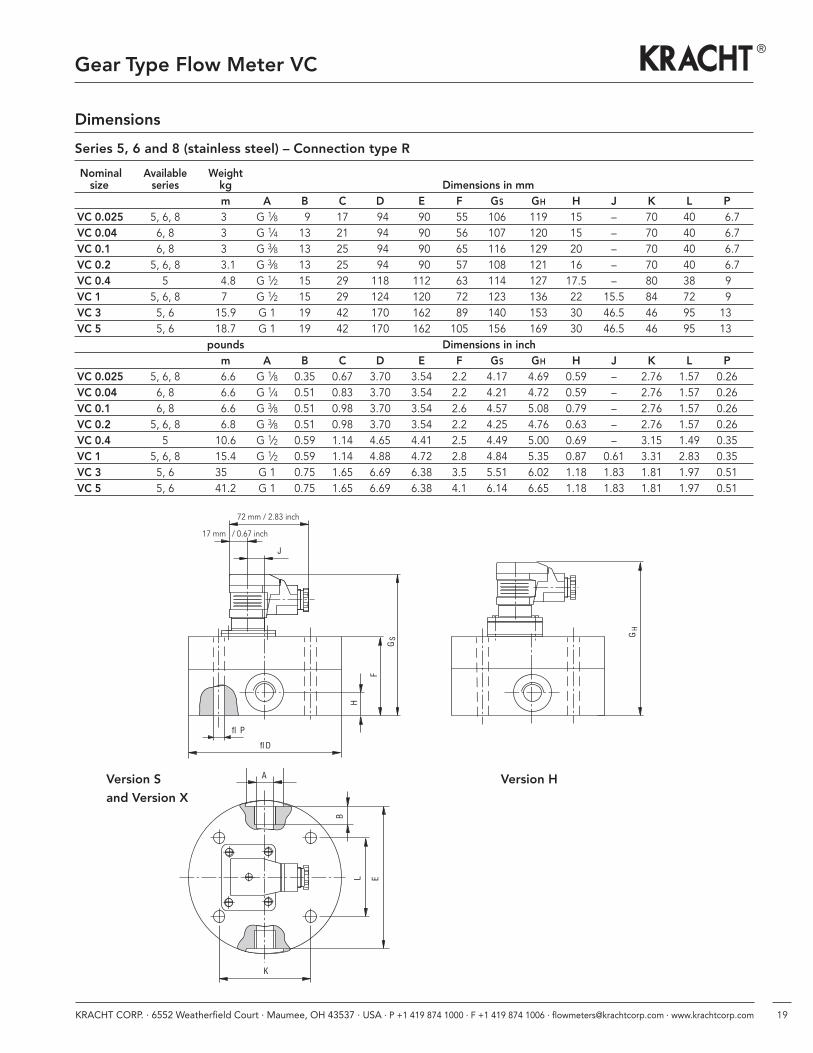
Series 5, 6 and 8 (stainless steel) – Connection type R
L E
K
B
A
GH
F
GS
H
fl P
fl D
J
72 mm / 2.83 inch
17 mm / 0.67 inch
Version Sand Version X
Version H
Nominal Available Weightsize series kg Dimensions in mm
m A B C D E F GS GH H J K L PVC 0.025 5, 6, 8 3.0 G 1⁄8 9 17 94 90 55 106 119 15 – 70 40 6.7VC 0.04 6, 8 3.0 G 1⁄4 13 21 94 90 56 107 120 15 – 70 40 6.7VC 0.1 6, 8 3.0 G 3⁄8 13 25 94 90 65 116 129 20 – 70 40 6.7VC 0.2 5, 6, 8 3.1 G 3⁄8 13 25 94 90 57 108 121 16 – 70 40 6.7VC 0.4 5 4.8 G 1⁄2 15 29 118 112 63 114 127 17.5 – 80 38 9.VC 1 5, 6, 8 70 G 1⁄2 15 29 124 120 72 123 136 22 15.5 84 72 9.VC 3 5, 6 15.9 G 1 19 42 170 162 89 140 153 30 46.5 46 95 13.VC 5 5, 6 18.7 G 1 19 42 170 162 105 156 169 30 46.5 46 95 13.
pounds Dimensions in inchm A B C D E F GS GH H J K L P
VC 0.025 5, 6, 8 6.6 G 1⁄8 0.35 0.67 3.70 3.54 2.2 4.17 4.69 0.59 – 2.76 1.57 0.26VC 0.04 6, 8 6.6 G 1⁄4 0.51 0.83 3.70 3.54 2.2 4.21 4.72 0.59 – 2.76 1.57 0.26VC 0.1 6, 8 6.6 G 3⁄8 0.51 0.98 3.70 3.54 2.6 4.57 5.08 0.79 – 2.76 1.57 0.26VC 0.2 5, 6, 8 6.8 G 3⁄8 0.51 0.98 3.70 3.54 2.2 4.25 4.76 0.63 – 2.76 1.57 0.26VC 0.4 5 10.6 G 1⁄2 0.59 1.14 4.65 4.41 2.5 4.49 5.00 0.69 – 3.15 1.49 0.35VC 1 5, 6, 8 15.4 G 1⁄2 0.59 1.14 4.88 4.72 2.8 4.84 5.35 0.87 0.61 3.31 2.83 0.35VC 3 5, 6 35,0 G 1 0.75 1.65 6.69 6.38 3.5 5.51 6.02 1.18 1.83 1.81 1.97 0.51VC 5 5, 6 41.2 G 1 0.75 1.65 6.69 6.38 4.1 6.14 6.65 1.18 1.83 1.81 1.97 0.51
Dimensions
20 KRACHT CORP. · 6552 Weatherfield Court · Maumee, OH 43537 · USA · P +1 419 874 1000 · F +1 419 874 1006 · [email protected] · www.krachtcorp.com
Gear Type Flow Meter VC
Dimensions
D64 mm / 2.52 inch
ML K
FGP
58 mm / 2.28 inch
C
36 m
m /
1.42 i
nch
J
P
A
12.4 mm /0.49 inch58 mm / 2.28 inch
14 mm /0.55 inch
36 m
m /
1.42 i
nch
Ø 4.3 mm /
0.17 inch46 mm /1.81 inch
6
NK
M L
P
Tightenningtorque
O-Ring
Connection dimensions
High temperature PLUS area Normal area
View X
Lengths orderingdesignations
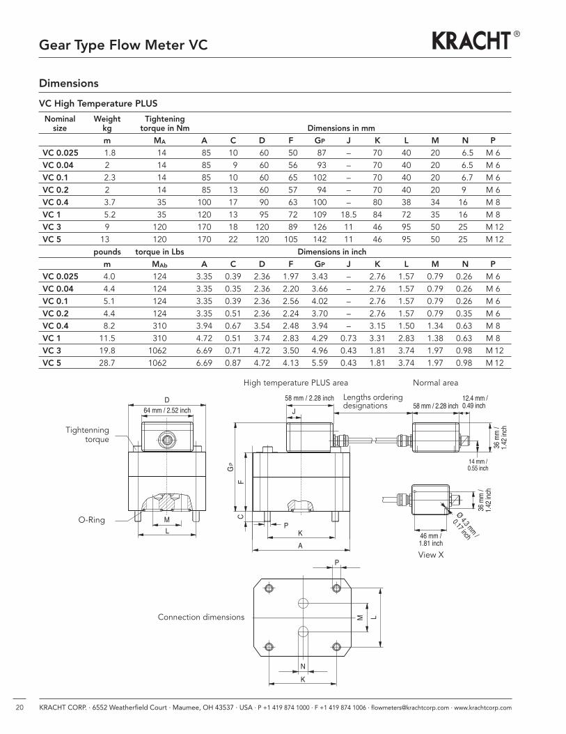
VC High Temperature PLUS
Nominal Weight Tighteningsize kg torque in Nm Dimensions in mm
m MA A C D F GP J K L M N PVC 0.025 1.8 14 85 10 60 50 87 – 70 40 20 6.5 M 6VC 0.04 2 14 85 9 60 56 93 – 70 40 20 6.5 M 6VC 0.1 2.3 14 85 10 60 65 102 – 70 40 20 6.7 M 6VC 0.2 2 14 85 13 60 57 94 – 70 40 20 90 M 6VC 0.4 3.7 35 100 17 90 63 100 – 80 38 34 160 M 8VC 1 5.2 35 120 13 95 72 109 18.5 84 72 35 160 M 8VC 3 9 120 170 18 120 89 126 11 46 95 50 250 M12VC 5 130 120 170 22 120 105 142 11 46 95 50 250 M12
pounds torque in Lbs Dimensions in inchm MAb A C D F GP J K L M N P
VC 0.025 4.0 124 3.35 0.39 2.36 1.97 3.43 – 2.76 1.57 0.79 0.26 M 6VC 0.04 4.4 124 3.35 0.35 2.36 2.20 3.66 – 2.76 1.57 0.79 0.26 M 6VC 0.1 5.1 124 3.35 0.39 2.36 2.56 4.02 – 2.76 1.57 0.79 0.26 M 6VC 0.2 4.4 124 3.35 0.51 2.36 2.24 3.70 – 2.76 1.57 0.79 0.35 M 6VC 0.4 8.2 310 3.94 0.67 3.54 2.48 3.94 – 3.15 1.50 1.34 0.63 M 8VC 1 11.5 310 4.72 0.51 3.74 2.83 4.29 0.73 3.31 2.83 1.38 0.63 M 8VC 3 19.8 10620 6.69 0.71 4.72 3.50 4.96 0.43 1.81 3.74 1.97 0.98 M12VC 5 28.7 10620 6.69 0.87 4.72 4.13 5.59 0.43 1.81 3.74 1.97 0.98 M12
21KRACHT CORP. · 6552 Weatherfield Court · Maumee, OH 43537 · USA · P +1 419 874 1000 · F +1 419 874 1006 · [email protected] · www.krachtcorp.com
Gear Type Flow Meter VC
Dimensions
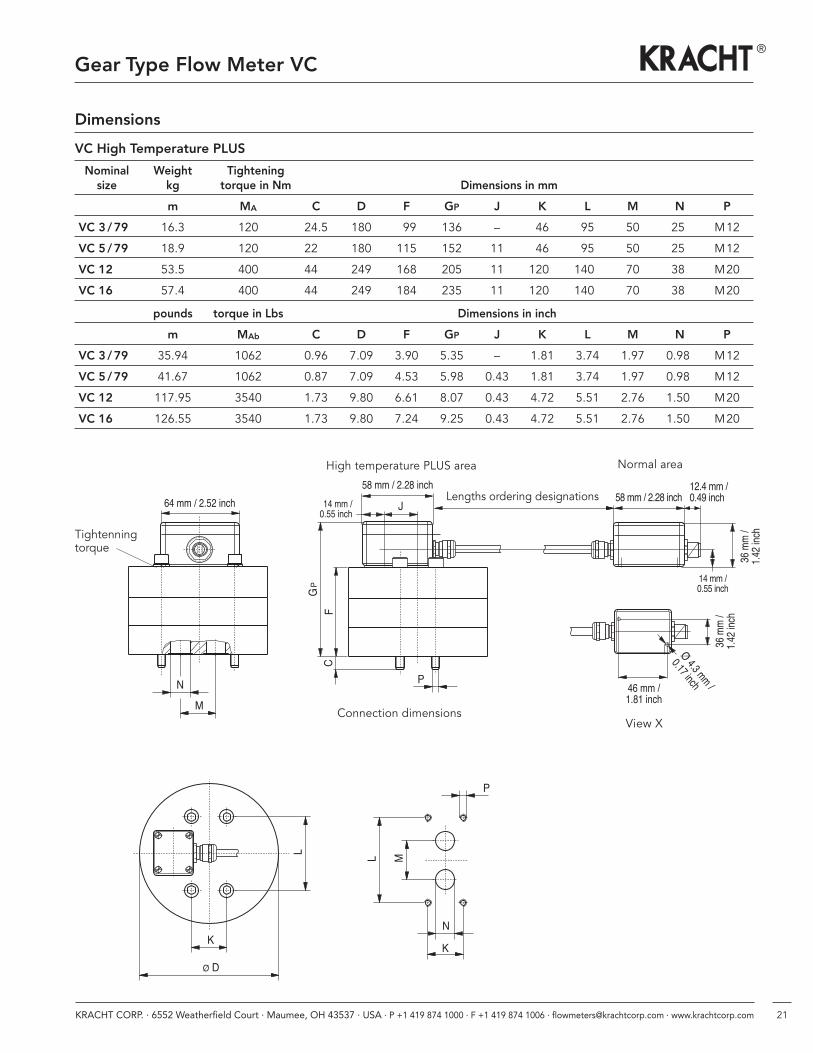
VC High Temperature PLUS
Nominal Weight Tighteningsize kg torque in Nm Dimensions in mm
m MA C D F GP J K L M N P
VC 3 /79 16.3 120 24.5 180 99 136 – 46 95 50 25 M12
VC 5 /79 18.9 120 22.0 180 115 152 11 46 95 50 25 M12
VC 12 53.5 400 44.0 249 168 205 11 1200 1400 70 38 M20
VC 16 57.4 400 44.0 249 184 235 11 1200 1400 70 38 M20
pounds torque in Lbs Dimensions in inch
m MAb C D F GP J K L M N P
VC 3 /79 35.94 1062 0.96 7.09 3.90 5.35 – 1.81 3.74 1.97 0.98 M12
VC 5 /79 41.67 1062 0.87 7.09 4.53 5.98 0.43 1.81 3.74 1.97 0.98 M12
VC 12 117.95 3540 1.73 9.80 6.61 8.07 0.43 4.72 5.51 2.76 1.50 M20
VC 16 126.55 3540 1.73 9.80 7.24 9.25 0.43 4.72 5.51 2.76 1.50 M20
P
J
MN
FGP
C
64 mm / 2.52 inch58 mm / 2.28 inch
14 mm /0.55 inch
36 m
m /
1.42 i
nch
Ø 4.3 mm /
0.17 inch46 mm /1.81 inch
36 m
m /
1.42 i
nch
12.4 mm /0.49 inch58 mm / 2.28 inch
14 mm /0.55 inch
Ø D
K
L
P
KN
ML
Connection dimensionsView X
High temperature PLUS area Normal area
Lengths ordering designations
Tightenningtorque
22 KRACHT CORP. · 6552 Weatherfield Court · Maumee, OH 43537 · USA · P +1 419 874 1000 · F +1 419 874 1006 · [email protected] · www.krachtcorp.com
Gear Type Flow Meter VC
A
K
E
R
øH
øG
JC
c
f
ed
X
LFB
P
M
N
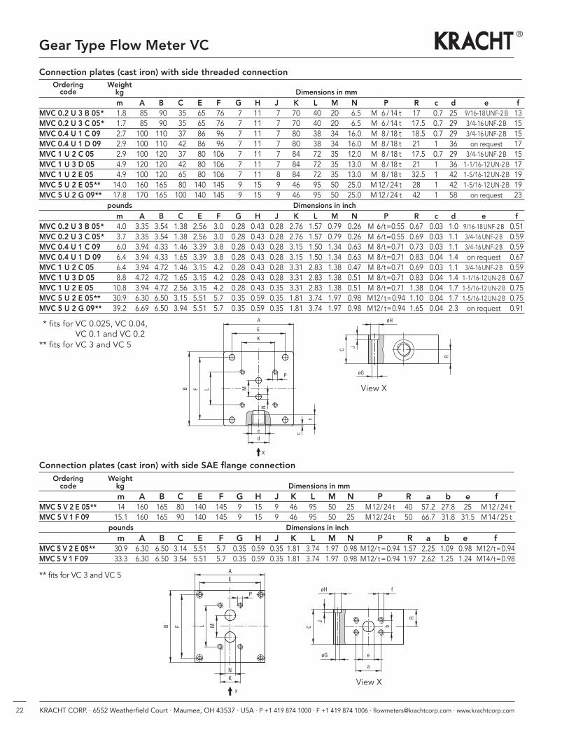
Connection plates (cast iron) with side threaded connection
Connection plates (cast iron) with side SAE flange connection
EA
J
C
øH f
R
øG
a
e
b
x
NK
FB ML
P
Ordering Weightcode kg Dimensions in mm
m A B C E F G H J K L M N P R a b e fMVC 5 V 2 E 05** 14 160 165 80 140 145 9 15 9 46 95 50 25 M12/24 t 40 57.2 27.8 25 M12/24 tMVC 5 V 1 F 09 15.1 160 165 90 140 145 9 15 9 46 95 50 25 M12/24 t 50 66.7 31.8 31.5 M14/25 t
pounds Dimensions in inchm A B C E F G H J K L M N P R a b e f
MVC 5 V 2 E 05** 30.9 6.30 6.50 3.14 5.51 5.7 0.35 0.59 0.35 1.81 3.74 1.97 0.98 M12/ t=0.94 1.57 2.25 1.09 0.98 M12/t=0.94MVC 5 V 1 F 09 33.3 6.30 6.50 3.54 5.51 5.7 0.35 0.59 0.35 1.81 3.74 1.97 0.98 M12/ t=0.94 1.97 2.62 1.25 1.24 M14/t=0.98
** fits for VC 3 and VC 5
Ordering Weightcode kg Dimensions in mm
m A B C E F G H J K L M N P R c d e fMVC 0.2 U 3 B 05* 1.8 85 90 35 65 76 7 11 7 70 40 20 6.5 M 6/14 t 17 0.7 25 9/16-18UNF-2B 13MVC 0.2 U 3 C 05* 1.7 85 90 35 65 76 7 11 7 70 40 20 6.5 M 6/14 t 17.5 0.7 29 3/4-16UNF-2B 15MVC 0.4 U 1 C 09 2.7 100 110 37 86 96 7 11 7 80 38 34 16.0 M 8/18 t 18.5 0.7 29 3/4-16UNF-2B 15MVC 0.4 U 1 D 09 2.9 100 110 42 86 96 7 11 7 80 38 34 16.0 M 8/18 t 21 1 36 on request 17MVC 1 U 2 C 05 2.9 100 120 37 80 106 7 11 7 84 72 35 12.0 M 8/18 t 17.5 0.7 29 3/4-16UNF-2B 15MVC 1 U 3 D 05 4.9 120 120 42 80 106 7 11 7 84 72 35 13.0 M 8/18 t 21 1 36 1-1/16-12UN-2B 17MVC 1 U 2 E 05 4.9 100 120 65 80 106 7 11 8 84 72 35 13.0 M 8/18 t 32.5 1 42 1-5/16-12UN-2B 19MVC 5 U 2 E 05** 14.0 160 165 80 140 145 9 15 9 46 95 50 25.0 M12/24 t 28 1 42 1-5/16-12UN-2B 19MVC 5 U 2 G 09** 17.8 170 165 100 140 145 9 15 9 46 95 50 25.0 M12/24 t 42 1 58 on request 23
pounds Dimensions in inchm A B C E F G H J K L M N P R c d e f
MVC 0.2 U 3 B 05* 4.0 3.35 3.54 1.38 2.56 3.0 0.28 0.43 0.28 2.76 1.57 0.79 0.26 M 6/t=0.55 0.67 0.03 1.0 9/16-18UNF-2B 0.51MVC 0.2 U 3 C 05* 3.7 3.35 3.54 1.38 2.56 3.0 0.28 0.43 0.28 2.76 1.57 0.79 0.26 M 6/t=0.55 0.69 0.03 1.1 3/4-16UNF-2B 0.59MVC 0.4 U 1 C 09 6.0 3.94 4.33 1.46 3.39 3.8 0.28 0.43 0.28 3.15 1.50 1.34 0.63 M 8/t=0.71 0.73 0.03 1.1 3/4-16UNF-2B 0.59MVC 0.4 U 1 D 09 6.4 3.94 4.33 1.65 3.39 3.8 0.28 0.43 0.28 3.15 1.50 1.34 0.63 M 8/t=0.71 0.83 0.04 1.4 on request 0.67MVC 1 U 2 C 05 6.4 3.94 4.72 1.46 3.15 4.2 0.28 0.43 0.28 3.31 2.83 1.38 0.47 M 8/t=0.71 0.69 0.03 1.1 3/4-16UNF-2B 0.59MVC 1 U 3 D 05 8.8 4.72 4.72 1.65 3.15 4.2 0.28 0.43 0.28 3.31 2.83 1.38 0.51 M 8/t=0.71 0.83 0.04 1.4 1-1/16-12UN-2B 0.67MVC 1 U 2 E 05 10.8 3.94 4.72 2.56 3.15 4.2 0.28 0.43 0.35 3.31 2.83 1.38 0.51 M 8/t=0.71 1.38 0.04 1.7 1-5/16-12UN-2B 0.75MVC 5 U 2 E 05** 30.9 6.30 6.50 3.15 5.51 5.7 0.35 0.59 0.35 1.81 3.74 1.97 0.98 M12/ t=0.94 1.10 0.04 1.7 1-5/16-12UN-2B 0.75MVC 5 U 2 G 09** 39.2 6.69 6.50 3.94 5.51 5.7 0.35 0.59 0.35 1.81 3.74 1.97 0.98 M12/ t=0.94 1.65 0.04 2.3 on request 0.91
** fits for VC 0.025, VC 0.04, VC 0.1 and VC 0.2
** fits for VC 3 and VC 5
View X
View X
23KRACHT CORP. · 6552 Weatherfield Court · Maumee, OH 43537 · USA · P +1 419 874 1000 · F +1 419 874 1006 · [email protected] · www.krachtcorp.com
Gear Type Flow Meter VC
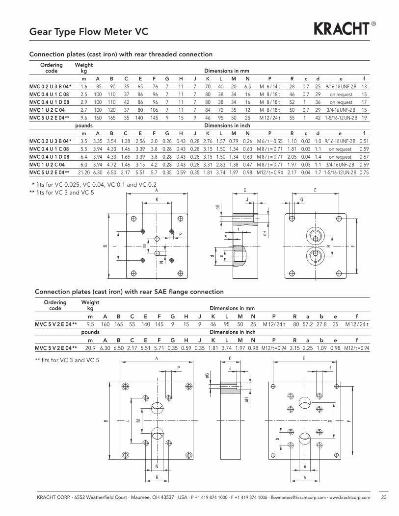
Connection plates (cast iron) with rear threaded connection
Connection plates (cast iron) with rear SAE flange connection
Ordering Weightcode kg Dimensions in mm
m A B C E F G H J K L M N P R a b e fMVC 5 V 2 E 04** 9.5 160 165 55 140 145 9 15 9 46 95 50 25 M12/24 t 80 57.2 27.8 25 M12 /24 t
pounds Dimensions in inch
m A B C E F G H J K L M N P R a b e fMVC 5 V 2 E 04** 20.9 6.30 6.50 2.17 5.51 5.71 0.35 0.59 0.35 1.81 3.74 1.97 0.98 M12/t=0.94 3.15 2.25 1.09 0.98 M12/t=0.94
** fits for VC 3 and VC 5
A
K
LB M
P
N
E
G
C
J
øH
øG
cf
ed
FR
A
P J
C
øH
øG
f
E
F
e
a
R
b
B
N
K
ML
Ordering Weightcode kg Dimensions in mm
m A B C E F G H J K L M N P R c d e f
MVC 0.2 U 3 B 04* 1.6 85 90 35 65 76 7 11 7 70 40 20 6.5 M 6 /14 t 28 0.7 25 9/16-18UNF-2B 13MVC 0.4 U 1 C 08 2.5 100 110 37 86 96 7 11 7 80 38 34 16 M 8/18 t 46 0.7 29 on request 15MVC 0.4 U 1 D 08 2.9 100 110 42 86 96 7 11 7 80 38 34 16 M 8/18 t 52 10 36 on request 17MVC 1 U 2 C 04 2.7 100 120 37 80 106 7 11 7 84 72 35 12 M 8/18 t 50 0.7 29 3/4-16UNF-2B 15MVC 5 U 2 E 04** 9.6 160 165 55 1400 145 9 15 9 46 95 50 25 M12 /24 t 55 10 42 1-5/16-12UN-2B 19
pounds Dimensions in inchm A B C E F G H J K L M N P R c d e f
MVC 0.2 U 3 B 04* 3.5 3.35 3.54 1.38 2.56 3.0 0.28 0.43 0.28 2.76 1.57 0.79 0.26 M6/ t=0.55 1.10 0.03 1.0 9/16-18UNF-2B 0.51MVC 0.4 U 1 C 08 5.5 3.94 4.33 1.46 3.39 3.8 0.28 0.43 0.28 3.15 1.50 1.34 0.63 M8/ t=0.71 1.81 0.03 1.1 on request 0.59MVC 0.4 U 1 D 08 6.4 3.94 4.33 1.65 3.39 3.8 0.28 0.43 0.28 3.15 1.50 1.34 0.63 M8/ t=0.71 2.05 0.04 1.4 on request 0.67MVC 1 U 2 C 04 6.0 3.94 4.72 1.46 3.15 4.2 0.28 0.43 0.28 3.31 2.83 1.38 0.47 M8/ t=0.71 1.97 0.03 1.1 3/4-16UNF-2B 0.59MVC 5 U 2 E 04** 21.20 6.30 6.50 2.17 5.51 5.7 0.35 0.59 0.35 1.81 3.74 1.97 0.98 M12/t=0.94 2.17 0.04 1.7 1-5/16-12UN-2B 0.75
** fits for VC 0.025, VC 0.04, VC 0.1 and VC 0.2** fits for VC 3 and VC 5
24 KRACHT CORP. · 6552 Weatherfield Court · Maumee, OH 43537 · USA · P +1 419 874 1000 · F +1 419 874 1006 · [email protected] · www.krachtcorp.com
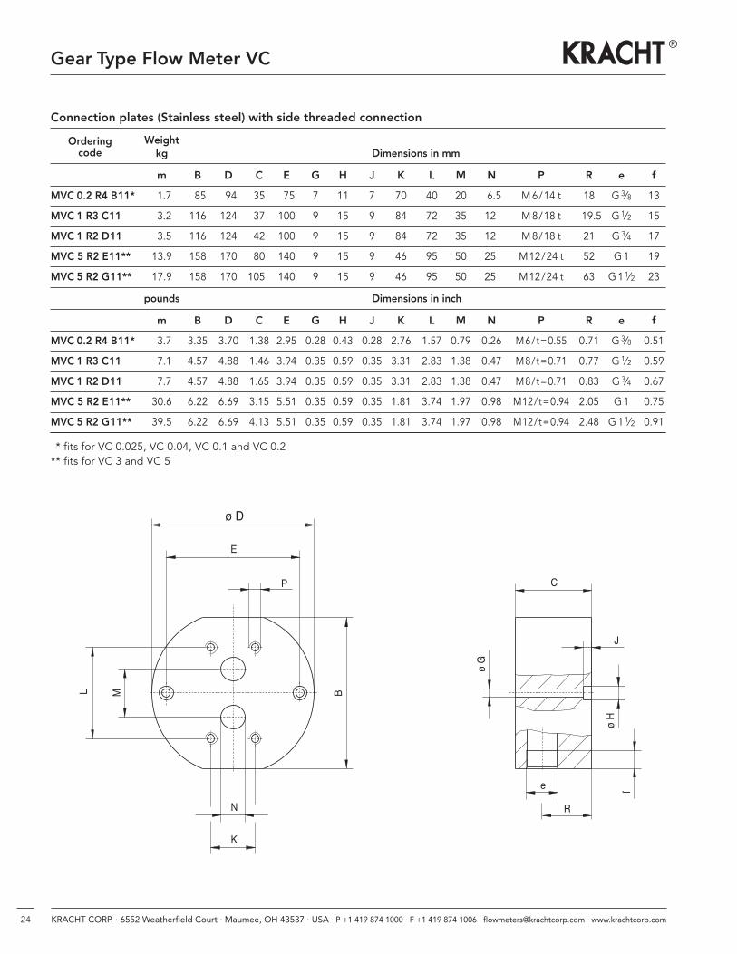
Connection plates (Stainless steel) with side threaded connection
Ordering Weightcode kg Dimensions in mm
m B D C E G H J K L M N P R e f
MVC 0.2 R4 B11* 1.7 85 94 35 75 7 11 7 70 40 20 6.5 M6/14 t 18 G3⁄8 13
MVC 1 R3 C11 3.2 116 124 37 100 9 15 9 84 72 35 12. M8/18 t 19.5 G1⁄2 15
MVC 1 R2 D11 3.5 116 124 42 100 9 15 9 84 72 35 12. M8/18 t 21 G3⁄4 17
MVC 5 R2 E11** 13.9 158 170 80 140 9 15 9 46 95 50 25. M12/24 t 52 G1 19
MVC 5 R2 G11** 17.9 158 170 1050 140 9 15 9 46 95 50 25. M12/24 t 63 G11⁄2 23
pounds Dimensions in inch
m B D C E G H J K L M N P R e f
MVC 0.2 R4 B11* 3.7 3.35 3.70 1.38 2.95 0.28 0.43 0.28 2.76 1.57 0.79 0.26 M6/t=0.55 0.71 G3⁄8 0.51
MVC 1 R3 C11 7.1 4.57 4.88 1.46 3.94 0.35 0.59 0.35 3.31 2.83 1.38 0.47 M8/t=0.71 0.77 G1⁄2 0.59
MVC 1 R2 D11 7.7 4.57 4.88 1.65 3.94 0.35 0.59 0.35 3.31 2.83 1.38 0.47 M8/t=0.71 0.83 G3⁄4 0.67
MVC 5 R2 E11** 30.6 6.22 6.69 3.15 5.51 0.35 0.59 0.35 1.81 3.74 1.97 0.98 M12/t=0.94 2.05 G1 0.75
MVC 5 R2 G11** 39.5 6.22 6.69 4.13 5.51 0.35 0.59 0.35 1.81 3.74 1.97 0.98 M12/t=0.94 2.48 G11⁄2 0.91
** fits for VC 0.025, VC 0.04, VC 0.1 and VC 0.2** fits for VC 3 and VC 5
B
K
N
L M
P
ø D
E
e fJ
ø H
ø G
C
R
Gear Type Flow Meter VC
25KRACHT CORP. · 6552 Weatherfield Court · Maumee, OH 43537 · USA · P +1 419 874 1000 · F +1 419 874 1006 · [email protected] · www.krachtcorp.com
Gear Type Flow Meter VC
Note
26 KRACHT CORP. · 6552 Weatherfield Court · Maumee, OH 43537 · USA · P +1 419 874 1000 · F +1 419 874 1006 · [email protected] · www.krachtcorp.com
Gear Type Flow Meter VC
Note

27KRACHT CORP. · 6552 Weatherfield Court · Maumee, OH 43537 · USA · P +1 419 874 1000 · F +1 419 874 1006 · [email protected] · www.krachtcorp.com
Gear Type Flow Meter VC
Note
KRACHT CORP. · 6552 Weatherfield Court · Maumee, OH 43537 · USA · P +1 419 874 1000 · F +1 419 874 1006
[email protected] · www.krachtcorp.com
VC / USA/02.19
Product Portfolio
®
Gear PumpsGear pumps for lubricating oil supply equipment, low pressure filling and feed systems, dosing and mixing systems.
HydraulicsSingle and multistage high pressure gear pumps and hydraulic motors for construction machinery, vehicle-mountedmachines.
Flow MeasurementGear, turbine and screw type flow meters and electronics for volume and flow metering techno logy in hydraulics, processing and laquering technology.
ValvesCetop directional control and proportionalvalves, pressure, quantity and stop valves forpipe and slab construction.


![Gear Type Flow Meter VC PULSE - KRACHTkracht.eu/uploads/tx_ttproducts/datasheet/VC-PULSE_GB_07-19.pdf · VC sensor resolution volume evaluation) at to standard VC Qnenn [pulse/rev.]](https://img.dokumen.tips/doc/110x75/5f67917605498e44032ea3dc/gear-type-flow-meter-vc-pulse-vc-sensor-resolution-volume-evaluation-at-to-standard.jpg)