Embed Size (px)
Citation preview

GDOT QC/QA Manual
GDOT QC/QA Program, Revision 7/06/2016
GDOT Quality Control and Quality Assurance Program 1. Introduction 2
1.1. QC/QA Objectives 2
1.2. Purpose 2
1.3. Definitions 3
1.4. Roles and Responsibilities 3
2. Quality Control Components 4
2.1. Introduction 4
2.2. Project Correspondence File 4
2.3. Coordination Meetings and Resolution of Design Issues 5
2.4. QA Review of State Waters and Stream Buffer Delineations 5
2.5. Constructability Review 5
2.6. Routine Formal Training 5
2.7. Design Standards and Guidelines 6
2.8. Design Software 6
2.9. Electronic Data Guidelines (EDG) and Plan Presentation Guidelines (PPG) 7
2.10. Engineering Calculations 7
3. Quality Assurance 8
4. QC/QA Documentation and Accountability 8
4.1. QA Review Stamp 9
4.2. Local/Consultant Projects 9
4.3. Quality Control Best Practices 10
Appendix A: QA Review Event Checklists
Appendix B: QC-QA Record Log
Appendix C: Design Calculation Review Form

GDOT QC/QA Manual
GDOT QC/QA Program, Revision 07/06/2016
1. Introduction 1.1. QC/QA Objectives
The GDOT Quality Control and Quality Assurance (QC/QA) Program has been developed by the Engineering Division of the Georgia Department of Transportation to ensure that engineering, design, plans and quantities developed by our design offices are supported by comprehensive studies and sound engineering judgment, comply with established policies, guidelines and standards, and contain appropriate design flexibility and cost saving measures.
The engineering managers within our design offices are responsible for reviewing and certifying the accuracy of the engineering and plans prepared by their staff. The QC/QA practices defined within this program focus on the roadway design office environment and may not reflect all business practices across the Department. This program may be modified to fit specific business practices and experience/skill levels within an office or design group.
This QC/QA Program is maintained by the State Design Policy Engineer who will routinely consult with Office Administrators to identify and document unique methods and practices that consistently result in higher quality work. These “Best Quality Control Practices” will be uniformly applied across the Department so that we are constantly improving our quality and efficiency in delivering projects.
In support of this QC/QA Program, the engineers within our design offices are committed to the application of established design policies, guidelines, and standards developed and published by the Georgia Department of Transportation (GDOT), the American Association of State Highway and Transportation Officials (AASHTO), the Federal Highway Administration (FHWA), the National Highway Institute (NHI), the Transportation Research Board (TRB), and the National Cooperative Highway Research Program (NCHRP). In addition, our design offices are committed to recruiting qualified engineers and supporting the professional development of those engineers including providing fundamental training in the fundamental engineering disciplines. See Section 2.6 for the types of training.
This QC/QA program also defines the coordination effort required between the DGM/DDE and the project team during the development of plans. This QC/QA program is to be used in addition to any current QC/QA procedures and publications that are in use by the Department such as, but not limited to, the Plan Development Process (PDP), Plan Presentation Guide (PPG), Electronic Data Guidelines (EDG), the Field Plan Review process (PFPR/FFPR), and the “Checklist for R/W Plans” and the “Designer’s Checklist for Plans Submittal to Contracts Administration”.
1.2. Purpose
The purpose of this QC/QA program is to:
define the QC/QA responsibilities of the Office Administrator (OH), Assistant Office Administrator (AOH)/District Preconstruction Engineer (DPE), Design Group Manager, and the Design Engineer (DE). The Design Engineer refers to the engineer preparing the design. This will normally be a Senior Design Engineer (SDE), Lead Design Engineer (LDE) or a Design Engineer (1, 2, or 3).

GDOT QC/QA Manual
GDOT QC/QA Program, Revision 07/06/2016
define the components of QC and QA required to develop roadway design projects;
define the frequency of specific QC activities and QA reviews;
define the methods of documenting QC/QA activities/reviews and individual accountability;
prevent errors from being introduced to the engineering, design, plans and cost estimates;
ensure decisions are supported by comprehensive studies and sound engineering judgment; and
identify individuals and their unique methods that reflect Best Quality Control Practices and apply those methods uniformly across the Design Groups/Squads.
1.3. Definitions
Quality Control: Refers to the daily processes, practices, and checks in place to control the quality of the engineering, design, plans, and quantities as they are being developed.
Quality Assurance: Refers to the formal high-level review of the project plans and quantities by an experienced engineering manager at strategic points in the plan development process, to certify that the plans and quantities meet established quality standards and provide for appropriate flexibility and cost savings before advancing to the next stage.
1.4. Roles and Responsibilities
Roles and responsibilities for QC/QA tasks are defined below in Table 1.
Table 1. Responsibility Matrix for QC/QA
Office/Position Quality Control Quality Assurance State Roadway Design Engineer (OH)
Implementation/Compliance/ Best Practices
Implementation/Compliance/ Best Practices
Office of Roadway Design
Assistant State Roadway Design Engineer (AOH)
Implementation/Compliance/ Best Practices
QA Review and certification for advancing design
Design Group Manager (DGM)
Practice & Certify QC Maintain QC/QA Record
Verify QA comments are implemented
Design Engineer (DE)1 Practice QC ---
District Design Office
District Preconstruction Engineer (DPE)
Implementation/Compliance/ Best Practices
QA Review and certification for advancing design
District Design Engineer (DDE)
Practice & Certify QC Maintain QC/QA Record
Verify QA comments are implemented
Design Engineer (DE) Practice QC --- 1 Refers to the engineer preparing the design. This will normally be a Senior Design Engineer (SDE), Lead Design Engineer (LDE) or a Design Engineer (1, 2, or 3).
GDOT QC/QA Manual
GDOT QC/QA Program, Revision 07/06/2016
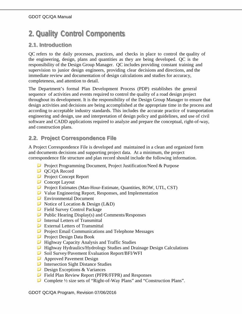
2. Quality Control Components 2.1. Introduction
QC refers to the daily processes, practices, and checks in place to control the quality of the engineering, design, plans and quantities as they are being developed. QC is the responsibility of the Design Group Manager. QC includes providing constant training and supervision to junior design engineers, providing clear decisions and directions, and the immediate review and documentation of design calculations and studies for accuracy, completeness, and attention to detail.
The Department’s formal Plan Development Process (PDP) establishes the general sequence of activities and events required to control the quality of a road design project throughout its development. It is the responsibility of the Design Group Manager to ensure that design activities and decisions are being accomplished at the appropriate time in the process and according to acceptable industry standards. This includes the accurate practice of transportation engineering and design, use and interpretation of design policy and guidelines, and use of civil software and CADD applications required to analyze and prepare the conceptual, right-of-way, and construction plans.
2.2. Project Correspondence File
A Project Correspondence File is developed and maintained in a clean and organized form and documents decisions and supporting project data. At a minimum, the project correspondence file structure and plan record should include the following information.
Project Programming Document, Project Justification/Need & Purpose QC/QA Record Project Concept Report Concept Layout Project Estimates (Man-Hour-Estimate, Quantities, ROW, UTL, CST) Value Engineering Report, Responses, and Implementation Environmental Document Notice of Location & Design (L&D) Field Survey Control Package Public Hearing Display(s) and Comments/Responses Internal Letters of Transmittal External Letters of Transmittal Project Email Communications and Telephone Messages Project Design Data Book Highway Capacity Analysis and Traffic Studies Highway Hydraulics/Hydrology Studies and Drainage Design Calculations Soil Survey/Pavement Evaluation Report/BFI/WFI Approved Pavement Design Intersection Sight Distance Studies Design Exceptions & Variances Field Plan Review Report (PFPR/FFPR) and Responses Complete ½ size sets of “Right-of-Way Plans” and “Construction Plans”.

GDOT QC/QA Manual
GDOT QC/QA Program, Revision 07/06/2016
Consultant Contract(s) and correspondence
Develop and maintain a Project Design Data Book (see Chapter 5 of the PDP for details). http://www.dot.ga.gov/doingbusiness/PoliciesManuals/roads/PDP/4050-1.pdf
2.3. Coordination Meetings and Resolution of Design Issues
The DGM/DDE will keep the Project Manager (PM) updated on design issues that affect the project’s scope, schedule, and budget. The PM will also be updated on any design issue that affects another office on the project team. Project team members include: Planning, OFM, Environmental Services, Location Bureau, District Field Surveys, Geotechnical Bureau, Bridge Design, Utilities, Traffic Operations, Right-Of-Way, and Construction. If issues do arise, the PM will conduct a meeting for the project team members to review scope items, discuss and resolve design issues, and assign deadlines.
2.4. QA Review of State Waters and Stream Buffer Delineations
Upon receiving Database Mapping, the designer should plot roll-plots of the project alignment with all topo drainage features displayed. The designer should mark all USGS blue-line streams on the roll-plots with blue highlighter, all existing topo drainage features with yellow highlighter, and all streams and buffers previously identified by the ecologist with blue and orange highlighters respectively. The roll plots should be submitted to the Office of Environmental Services for QA review with cover letter (Appendix B) attached.
2.5. Constructability Review
During preliminary design, the PM is responsible for holding a Constructability Review with the District Construction Engineer (See Appendix C for cover letter). The meeting should be scheduled once the horizontal and vertical geometry has been established, the initial cross sections are available, and SUE survey data has been received (for SUE projects). The purpose of the meeting is to identify and resolve issues with staging and constructability before the geometric design of the project is completed and ROW Plans are developed (see PDP, Chapter 6; Constructability Review in Preliminary Design). http://www.dot.ga.gov/doingbusiness/PoliciesManuals/roads/PDP/4050-1.pdf
2.6. Routine Formal Training
Provide routine formal training (i.e., GDOT Practical Design Training program) to design engineers in the following engineering disciplines:
a. Highway Capacity Analysis and Traffic Studies;
b. Geometric Design of Roadways;
c. Highway Hydraulics and Hydrology;
d. Pavement Design;
e. Erosion and Sediment Control;
f. Signal Design; and

GDOT QC/QA Manual
GDOT QC/QA Program, Revision 07/06/2016
g. Roundabout Design.
The focus of the training is on the fundamental engineering principles, the current applicable design policy and guidelines, and hands-on practice of the required calculations and the use of the design software.
2.7. Design Standards and Guidelines
The GDOT Design Policy Manual is the primary resource for design policies required by the Georgia Department of Transportation. A complete listing of all design publications can be found within the online version of the GDOT Design Policy Manual at the following link: http://www.dot.ga.gov/doingbusiness/PoliciesManuals/roads/designpolicies/Pages/DesignPolicyManual.aspx
2.8. Design Software
The following software is accepted by the Department for developing, analyzing, and supporting project design elements. See R.O.A.D.S. web page to download the GDOT software noted below.
Highway Capacity and Traffic Studies
HCS+ (Highway Capacity Software by McTrans) – implements the HCM2010.
SYNCHRO – traffic simulation modeling – optimizing traffic signal timing.
TSIS (CORSIM), VISSIM – traffic simulation modeling – combined signal and freeway systems.
SIDRA, Arcady, GDOT Roundabout Tool – roundabout capacity
Refer to the GDOT Capacity Software Decision Guide for selection of the appropriate guidance
Geometric Design of Roadways
Bentley MicroStation V8i (current) & J (Past) – computer aided drafting & design (CADD)
INROADS/Bentley (current), CAiCE/Autodesk (past) – civil design software.
AUTOTURN – automated vehicle turning specifications and geometry
Highway Hydraulics and Hydrology / Drainage Design / Erosion Control
StormCAD (Bentley) – longitudinal drainage system design.
FlowMaster (Bentley) – hydraulic calculator for gutter spread, spacing inlets, sizing pipes, and open channel flow.
CulvertMaster (Bentley) – culvert design
HY8 (FHWA) – culvert design
HEC-RAS (COE) – stream modeling software, primarily for bridge culverts that require FEMA coordination.
PondPack (Bentley) – design of detention ponds and water quality ponds.
GDOT QC/QA Manual
GDOT QC/QA Program, Revision 07/06/2016
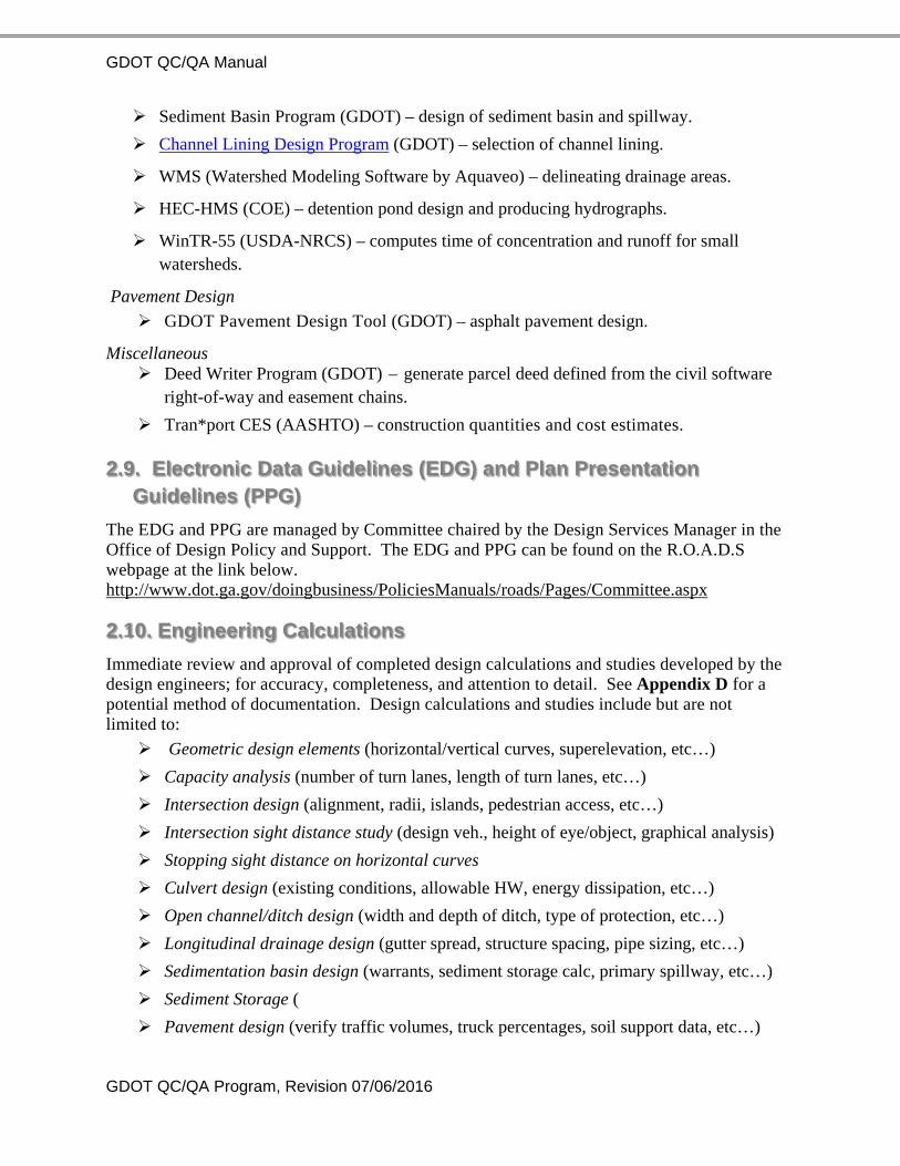
Sediment Basin Program (GDOT) – design of sediment basin and spillway.
Channel Lining Design Program (GDOT) – selection of channel lining.
WMS (Watershed Modeling Software by Aquaveo) – delineating drainage areas.
HEC-HMS (COE) – detention pond design and producing hydrographs.
WinTR-55 (USDA-NRCS) – computes time of concentration and runoff for small watersheds.
Pavement Design
GDOT Pavement Design Tool (GDOT) – asphalt pavement design.
Miscellaneous Deed Writer Program (GDOT) – generate parcel deed defined from the civil software
right-of-way and easement chains.
Tran*port CES (AASHTO) – construction quantities and cost estimates.
2.9. Electronic Data Guidelines (EDG) and Plan Presentation Guidelines (PPG)
The EDG and PPG are managed by Committee chaired by the Design Services Manager in the Office of Design Policy and Support. The EDG and PPG can be found on the R.O.A.D.S webpage at the link below. http://www.dot.ga.gov/doingbusiness/PoliciesManuals/roads/Pages/Committee.aspx
2.10. Engineering Calculations
Immediate review and approval of completed design calculations and studies developed by the design engineers; for accuracy, completeness, and attention to detail. See Appendix D for a potential method of documentation. Design calculations and studies include but are not limited to:
Geometric design elements (horizontal/vertical curves, superelevation, etc…)
Capacity analysis (number of turn lanes, length of turn lanes, etc…)
Intersection design (alignment, radii, islands, pedestrian access, etc…)
Intersection sight distance study (design veh., height of eye/object, graphical analysis)
Stopping sight distance on horizontal curves
Culvert design (existing conditions, allowable HW, energy dissipation, etc…)
Open channel/ditch design (width and depth of ditch, type of protection, etc…)
Longitudinal drainage design (gutter spread, structure spacing, pipe sizing, etc…)
Sedimentation basin design (warrants, sediment storage calc, primary spillway, etc…)
Sediment Storage (
Pavement design (verify traffic volumes, truck percentages, soil support data, etc…)

GDOT QC/QA Manual
GDOT QC/QA Program, Revision 07/06/2016
Roundabout studies (fastest path, truck turning swept path, stopping sight distance, intersection sight distance, etc…)
3. Quality Assurance Refers to the formal high-level review of the project plans and quantities by an experienced engineering manager at strategic points in the plan development process, to certify that the plans and quantities meet established quality standards and provide for appropriate flexibility and cost savings before advancing to the next stage. Essentially, quality assurance is the process of enforcing quality control standards at strategic points in project development. Quality Assurance is the responsibility of the AOH/DPE positions.
A series of QA Reviews are conducted by the AOH/DPE during project development with the support of the DGM/DDE, consultant (if applicable), the DE, and other appropriate members of the project team. At a minimum, a QA Review is required at the following milestones/strategic points in the plan development process.
1. Concept Report & Layout Review
2. Geometric Design Review
3. Preliminary Plans Review (QA Stamp required on plans) (defined on following page)
4. Right-Of-Way Plans Review
5. FFPR Plans Review (QA Stamp required on plans) (defined on following page)
A. Corrected FFPR Plan Set
6. Final Plans Submission Review.
It is the responsibility of the AOH/DPE to schedule the QA Review meetings with the DGM/DDE and DE. The DGM/DDE should provide the AOH/DPE with the “QC/QA Record” (defined below) and the plans prior to the review meeting. Engineering calculations and summary of quantities should also be provided at the review meeting, if applicable. The AOH/DPE should not allow a project design to advance to the next stage until they are satisfied that QC has occurred and the “QC/QA Record” is in order as defined by this Program.
4. QC/QA Documentation and Accountability For each project, a hardcopy record of QC activities and QA Reviews should be maintained in one location by the DGM/DDE and DE. A folder named, “QC/QA Record” should be placed in the front-end of the Project Correspondence Files for each project. See Appendix A of this program for form titled “QC/QA Record”. The purpose of the QC/QA Record is to document that QC activities and QA reviews have occurred for critical design activities and to ensure individual accountability throughout project development. This includes, but is not limited to recording activities such as:
QC - periodic review of the project Design Data Book for completeness and accuracy.
QC - review of design calculations and studies provided by design engineers (see Section 2.2 Project Correspondence File of this program for documentation).
QC - review of all software output results developed by design engineers.

GDOT QC/QA Manual
GDOT QC/QA Program, Revision 07/06/2016
QA - when QA requests are sent to project team members.
QA - formal QA reviews (1-6) of reports, calculations, plans, and quantities.
The AOH/DPE shall complete the QA Review (1-6) Checklist(s) and sign and date the report at the bottom of the page and file in the project “QC/QA Record” folder.
The “QC/QA Record” folder shall also contain major recommendations resulting from the formal QA Reviews (1-6) conducted by the AOH/DPE.
When requesting PFPR and FFPR, the letter addressed to Engineering Services shall also include the respective QA Review Checklist signed and dated by the AOH/DPE. The Office Head should not allow a project to advance to PFPR or FFPR without the respective QA Review Checklist signed and dated, to maintain accountability.
Plans undergoing a QA Review for “Preliminary Plans Review” and “FFPR Plans Review” should be stamped, signed, and dated by the AOH/DPE, DGM/DDE, and DE according to the directions provided in Section 4.1, QA Review Stamp of this manual.
4.1. QA Review Stamp
For accountability, during the QA Review for “Preliminary Plans Review” and “FFPR Plans Review”, each sheet within the plan set should be stamped with the red stamp below and signed and dated by the individual(s) responsible for the QA Review, back-checking to verify the issue is valid, correcting the plans, and verifying that the plans have been corrected appropriately. These record sets of plans should be retained until after the project has been constructed and “Final Acceptance” has been received.
4.2. Local/Consultant Projects
At the discretion of the Office Head, projects developed by consultant engineering firms for local governments may be processed through these six QA Review events. The Consultant Oversight Group will not stamp or certify the quality of plans developed by a consultant, but will make comments or request additional information required to support decisions or judgments. Under no circumstance does a QA Review by GDOT release the consultant from their contractual responsibilities involving QC/QA or from professional liability involving the engineering, plans, quantities and cost estimates, or from recovery of damages that result from errors and omissions in the plans.
QA REVIEW Checked………………… Date……….... Back-checked………....…Date……….... Corrected………………..Date………… Verified…………………. Date…………
AOH/DPE DGM/DDE or DE
DE DGM/DDE
GDOT QC/QA Manual
GDOT QC/QA Program, Revision 07/06/2016
4.3. Quality Control Best Practices
In order to constantly look for ways to improve the quality of the engineering, design, plans and cost estimates, the State Design Policy Engineer will consult with the Office Head and AOH/DPE (at a minimum annually) to identify individuals and methods that reflect Best Quality Control Practices. Performance Measures (P&P 2440-2) documented by Engineering Services at Concept Review, PFPR, and FFPR may be used to supplement this assessment. Those individuals with an outstanding record of quality design will be consulted to identify their specific training, methods, and practices. Those QC methods and practices will be documented by the State Design Policy Engineer and uniformly applied across the Design Groups by the Office Administrators on a continuous basis.
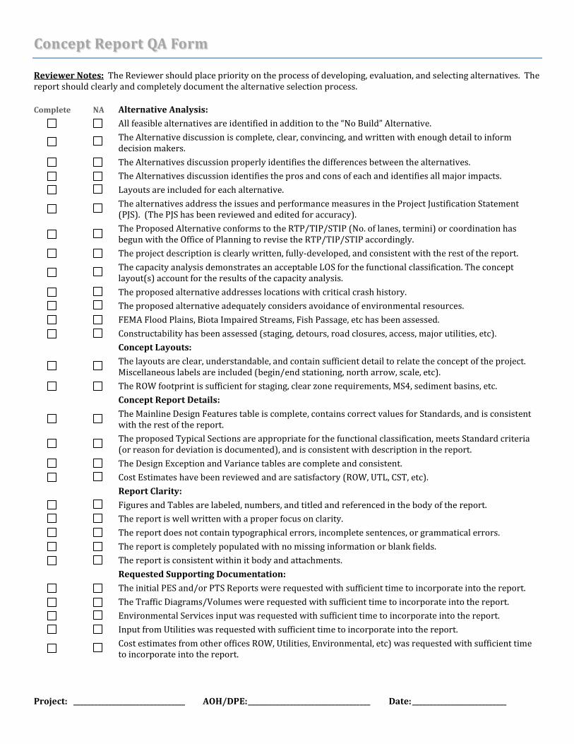
Concept Report QA Form Reviewer Notes: The Reviewer should place priority on the process of developing, evaluation, and selecting alternatives. The report should clearly and completely document the alternative selection process. Complete NA Alternative Analysis: All feasible alternatives are identified in addition to the “No Build” Alternative. The Alternative discussion is complete, clear, convincing, and written with enough detail to inform
decision makers. The Alternatives discussion properly identifies the differences between the alternatives. The Alternatives discussion identifies the pros and cons of each and identifies all major impacts. Layouts are included for each alternative. The alternatives address the issues and performance measures in the Project Justification Statement
(PJS). (The PJS has been reviewed and edited for accuracy). The Proposed Alternative conforms to the RTP/TIP/STIP (No. of lanes, termini) or coordination has
begun with the Office of Planning to revise the RTP/TIP/STIP accordingly. The project description is clearly written, fully-developed, and consistent with the rest of the report. The capacity analysis demonstrates an acceptable LOS for the functional classification. The concept
layout(s) account for the results of the capacity analysis. The proposed alternative addresses locations with critical crash history. The proposed alternative adequately considers avoidance of environmental resources. FEMA Flood Plains, Biota Impaired Streams, Fish Passage, etc has been assessed. Constructability has been assessed (staging, detours, road closures, access, major utilities, etc).
Concept Layouts: The layouts are clear, understandable, and contain sufficient detail to relate the concept of the project.
Miscellaneous labels are included (begin/end stationing, north arrow, scale, etc). The ROW footprint is sufficient for staging, clear zone requirements, MS4, sediment basins, etc. Concept Report Details: The Mainline Design Features table is complete, contains correct values for Standards, and is consistent
with the rest of the report. The proposed Typical Sections are appropriate for the functional classification, meets Standard criteria
(or reason for deviation is documented), and is consistent with description in the report. The Design Exception and Variance tables are complete and consistent. Cost Estimates have been reviewed and are satisfactory (ROW, UTL, CST, etc). Report Clarity: Figures and Tables are labeled, numbers, and titled and referenced in the body of the report. The report is well written with a proper focus on clarity. The report does not contain typographical errors, incomplete sentences, or grammatical errors. The report is completely populated with no missing information or blank fields. The report is consistent within it body and attachments. Requested Supporting Documentation: The initial PES and/or PTS Reports were requested with sufficient time to incorporate into the report. The Traffic Diagrams/Volumes were requested with sufficient time to incorporate into the report. Environmental Services input was requested with sufficient time to incorporate into the report. Input from Utilities was requested with sufficient time to incorporate into the report. Cost estimates from other offices ROW, Utilities, Environmental, etc) was requested with sufficient time
to incorporate into the report.
Project: ________________________________ AOH/DPE: ___________________________________ Date: ___________________________

Geometric Review QA Form Reviewer Notes: The QA review and scoring of the geometric design should focus on the geometric footprint of the project. Both the design and its corresponding documentation should be reviewed. Acceptable NA Horizontal Alignments * Horizontal Curves meet minimum radius (considering tightest vehicle path) Curve tangents match bearing on plan sheets. *Intersection Skew angles meet standard values (or DE/DV documented). Horizontal Curves are long enough to fit SE transitions. *Horizontal Curves have proper SE rate (reasonable emax selected for alignment, and correct ed
selected based on speed, radius, and emax). SE transition lengths and locations are appropriate for typical curves. SE transitions have been considered at special cases: side street rotation to mainline,
reverse/compound curves, shifting transitions away from bridges/intersections. SE transitions with flat cross slopes are located away from low points in the profile. Vertical Alignments *K-values meet required minimum values *Required Vertical Clearance is demonstrated over roadways, waterways, and railroads *Maximum and minimum grades are within Standard values. Side street profile elevation matches mainline. Side street starting grade matches mainline cross slope
at skew angle. Side street profile meets break-over values? Alignment can accommodate mill and overlay, according to typical section ranges Typical Sections Typical Sections match concept report (both attachment and table) *Typical Sections meet Standards (or otherwise documented) including widths, cross slopes, complete
streets (see table below) and is accurately dimensioned. Typical Section coverage is sufficient to describe work (mill & overlay, full depth, NC, SE). Typical Section station ranges are accurate and consistent with cover, plan, profile, and cross sections. Profile Grade Line and Axis of Rotation location are correct/reasonable. Cross Sections *Clear zone is provided throughout project. Guardrail is proposed in appropriate locations. Cross sections reflect correct shoulder width, cross
slopes, and account for anchor pads. Cross sections are consistent with plan view (widths, pavement cross slope, presence of turn lanes,
cut/fill limits, ditches, guardrail locations, etc.). Cross sections are consistent with profiles. Plan View Sufficient space is provided between construction limits and existing or required ROW/Easements for
construction and BMP installation. The location and spacing of median openings is reasonable and meet guidelines. Vehicle turning movements are accommodated. Design Data Book contains essential calculations related to the preliminary geometry. *May pertain to a controlling criteria. Project: ________________________________ AOH/DPE: ___________________________________ Date: ___________________________

Preliminary Plan Review QA Form Reviewer Notes: The QA review and scoring of the geometric design should focus on the overall footprint of the project. Both the design and its corresponding documentation should be reviewed. Acceptable NA Horizontal Alignments * Horizontal Curves meet minimum radius (considering tightest vehicle path) *Intersection Skew angles meet standard values (or DE/DV documented). *Horizontal Curves have proper SE rate (reasonable emax selected for alignment, and correct ed
selected based on speed, radius, and emax). Vertical Alignments *K-values meet required minimum values *Required Vertical Clearance is demonstrated over roadways, waterways, and railroads *Maximum and minimum grades are within Standard values. Side street profile elevation matches mainline. Side street starting grade matches mainline cross slope
at skew angle. Side street profile meets break-over values. Alignment can accommodate mill and overlay, according to typical section ranges. Typical Sections Typical Sections match concept report (both attachment and table) *Typical Sections meet Standards (or otherwise documented) including widths, cross slopes, complete
streets (see table below) and is accurately dimensioned. Typical Section coverage is sufficient to describe work (mill & overlay, full depth, NC, SE). Typical Section station ranges are accurate and consistent with cover, plan, profile, and cross sections. Profile Grade Line and Axis of Rotation location are correct/reasonable. All applicable Typical Section details are included (turn lanes, guardrail, pavement fabric, class B, P7) The minimum number of Typical Sections needed to adequately describe the typical work is given. Cross Sections *Clear zone is provided throughout project. Guardrail is proposed in appropriate locations. Cross sections reflect correct shoulder width, cross
slopes, and account for anchor pads. Cross sections are consistent with plan view (widths, pavement cross slope, presence of turn lanes,
cut/fill limits, ditches, guardrail locations, etc.) and profile. Soil Survey/Pavement Evaluation/UST recommendations have been adequately addressed. Plan View Required R/W and Easements are adequate to account for construction limits, BMPs, and
construction operations ADA requirements are appropriately addressed within the project design. Access is addressed for each parcel along the roadway, including provisions for U-Turns if needed. Misc Labels are included (strain poles, WCRs, concrete islands, ESA boundaries, etc) Plans are clean, legible, have proper scale, line weights, north arrows, and matchlines. (EDG/PPG met) Construction Layout has proper detail (if needed). Drainage Hydrology Calculations are reasonable. Correct methodology was used to determine peak flow. Hydraulic Calculations are reasonable. Gutter spread, HW calcs standards are met. FEMA, Biota Impaired Streams, and Fish Passage have been considered. Drainage Layout maintains sufficient ROW, pipe cover, and minimizes number of crossings.

Preliminary Plan Review QA Form Acceptable NA Staging / Erosion Control Staging is consistent with constructability review. Staging Plans are clear (areas of traffic / construction clear). Cross Section provided in critical areas. Sediment Basin locations and sizes have been determined properly. Miscellaneous Preliminary Bridge Plans are consistent with the roadway geometric design. Signing and Marking is reasonable Strain Poles have been properly located and labeled. Design Data Book is complete and accurate. Pavement Design has been approved. Coordination with FAA has occurred is project is within 5 miles of an airport or aviation facility. Completed NA Requests PES and/or PTS Reports were requested with sufficient time to incorporate into the design. Preliminary Bridge Layout was requested with sufficient time to incorporate into the design. First Submission Utilities was submitted with sufficient time to incorporate into the design. Submission to Environmental for Assessment of Effects was requested with sufficient time to
incorporate into the design. Constructability Review was requested and held with sufficient time to incorporate into the design. Railroad submittals were completed with sufficient time to incorporate comments into the design. *May pertain to a controlling criteria. Project: ________________________________ AOH/DPE: ___________________________________ Date: ___________________________

Right of Way Plan Review QA Form Reviewer Notes: The QA review and scoring of the RW Plans should focus on the overall footprint as well as adherence to standard plan presentation requirements. Acceptable NA Right of Way Footprint PFPR Comments pertaining to ROW footprint have been implemented. ROW and Easements are sufficient for construction activities. ROW and Easements are sufficient to accommodate Staging activities. ROW and Easements are sufficient to accommodate Erosion Control Devices. ROW and Easements are sufficient to accommodate Utility Relocations. ROW and Easements are sufficient to accommodate Permanent BMPS (MS4). ROW and Easements are sufficient to accommodate Strain Poles. ROW and Easements are sufficient to accommodate Stream Relocations. ROW and Easements are sufficient to accommodate Lighting. Parcel Access Split Parcels have sufficient access. Driveway Types are reasonable. Sufficient length is given to accommodate DW type (i.e. sidewalk
around dustpan.). Driveway profiles match plan view. Appropriate design vehicles are considered for driveway type, grade, and circulatory issues. Proposed Begin/End limited access is reasonable. Existing and Proposed Limited Access is labeled. Plan Presentation ROW Plans are developed in accordance with the RW Plans Checklist. Easements are labeled properly. Data tables are accurate and can be traced easily. Environmental Commitments that affect ROW are addressed in the plans (e.g. stay off historic trees,
access needed to plant, maintain, etc) Required ROW and easements on railroad property has been reviewed by Utilities. Project: ________________________________ AOH/DPE: ___________________________________ Date: ___________________________

Final Field Plan Review QA Form Reviewer Notes: The QA review and scoring of the FFPR Plan set and design should focus on the sections not included in the PFPR plan set including finalized ESPCP, finalized staging, S&PM plans, and Summary of Quantities. Acceptable NA General Considerations All applicable PFPR comments have been adequately addressed with the FFPR Plans. Environmental Commitments are addressed in the plans (ERIT and plan sheets). Final Bridge Plans are consistent with the roadway geometric design. The pavement design is consistent with the approved design (traffic/design year/structure). All needed special provisions are completed. Coordination has been completed for special provisions
108 and 150. Coordination with FAA has occurred is project is within 5 miles of an airport or aviation facility. Horizontal Alignments * Horizontal Curves meet minimum radius (considering tightest vehicle path) *Intersection Skew angles meet standard values (or DE/DV documented). *Horizontal Curves have proper SE rate (reasonable emax selected for alignment, and correct ed
selected based on speed, radius, and emax). Vertical Alignments *K-values meet required minimum values *Required Vertical Clearance is demonstrated over roadways, waterways, and railroads *Maximum and minimum grades are within Standard values. Alignment can accommodate mill and overlay, according to typical section ranges. Typical Sections Typical Sections match concept report (both attachment and table) *Typical Sections meet Standards (or otherwise documented) including widths, cross slopes, complete
streets (see table below) and is accurately dimensioned. Typical Section coverage is sufficient to describe work (mill & overlay, full depth, NC, SE). Typical Section station ranges are accurate and consistent with cover, plan, profile, and cross sections. All applicable Typical Section details are included (turn lanes, guardrail, pavement fabric, class B, P7) The minimum number of Typical Sections needed to adequately describe the typical work is given. Cross Sections *Clear zone is provided throughout project. Guardrail is proposed in appropriate locations. Cross sections reflect correct shoulder width, cross
slopes, and account for anchor pads. Cross sections are consistent with plan view (widths, pavement cross slope, presence of turn lanes,
cut/fill limits, ditches, guardrail locations, etc.) and profile. Soil Survey/Pavement Evaluation/UST recommendations have been adequately addressed. Quantities Summary of Quantities are complete and reasonable. All ancillary items are properly summarized (Utility, Lighting, Landscaping, items required by special
provisions, etc. ). CES report matches the Summary of Quantities.

Final Field Plan Review QA Form Acceptable NA Plan View Plans reflect commitments from ROW negotiations. All utility relocations / notes are adequately shown on the plans. Power pole, lighting pole, etc are
located outside of the clear zone or are protected. Utilities (including lighting) have been reviewed for conflicts with drainage or other design features. Plans are clean, legible, have proper scale, line weights, north arrows, and matchlines. (EDG/PPG met) Staging / Erosion Control Staging alignments, profiles, and cross sections are correct and tie to exist/final surfaces Staging narrative sufficiently describes the staging sequence. Notes for temp pedestrian/ADA bridge,
and/or drainage requirements are given if needed. Detour plan sheet is included if applicable. ESPCP is adequately designed and complies with the Permit. Notes are complete; monitoring location
is reasonable; stream buffer table is complete; sediment storage table is accurate. Completed NA Requests PES and/or PTS Reports were requested with sufficient time to incorporate into the design. Second Submission Utilities was submitted with sufficient time to incorporate into the design. Submission to Environmental for Ecological Lockdown was submitted. Constructability Review was requested and held with sufficient time to incorporate into the design. Railroad submittals were completed with sufficient time to incorporate comments into the design. *May pertain to a controlling criteria. Project: ________________________________ AOH/DPE: ___________________________________ Date: ___________________________

Final Plans Review QA Form Acceptable NA General Considerations All applicable FFPR comments have been adequately addressed with the Final Plans. Environmental Commitments are addressed in the plans (ERIT and plan sheets). Final Bridge Plans are consistent with the roadway geometric design. ESPCP is consistent with the latest GDOT NPDES General Permit Guidelines published on the ROADS
website. All needed special provisions are completed. Coordination has been completed for special provisions
108 and 150. Quantities Summary of Quantities are complete and reasonable. All ancillary items are properly summarized (Utility, Lighting, Landscaping, items required by special
provisions, etc. ). CES report matches the Summary of Quantities. Plans Package All needed special provisions are completed. Coordination has been completed for special provisions
108 and 150. The TMP is written and adequate. The Notice of Intent is accurate and complete. The Designer’s Checklist is accurate and complete. Project: ________________________________ AOH/DPE: ___________________________________ Date: ___________________________

Page | 1
QC/QA RECORD P.I. NO. County: Project Description: Office:
Lead Engineer: DGM/Senior Design Engineer: Assistant Office Head:
Date Originator Reviewer Item(s) Reviewed Comment
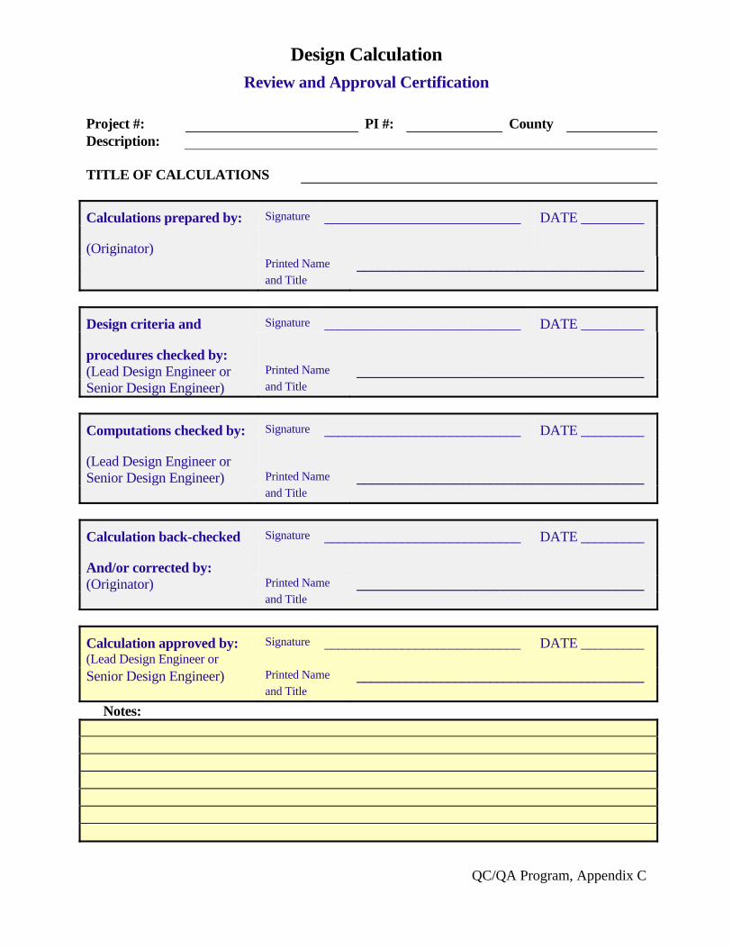
QC/QA Program, Appendix C
Design Calculation
Review and Approval Certification
Project #: PI #: County Description: TITLE OF CALCULATIONS
Calculations prepared by: Signature ____________________________ DATE _________
(Originator)
Printed Name _________________________________________ and Title
Design criteria and Signature ____________________________ DATE _________
procedures checked by:
(Lead Design Engineer or Printed Name _________________________________________ Senior Design Engineer) and Title
Computations checked by: Signature ____________________________ DATE _________
(Lead Design Engineer or
Senior Design Engineer) Printed Name _________________________________________ and Title
Calculation back-checked Signature ____________________________ DATE _________
And/or corrected by:
(Originator) Printed Name _________________________________________ and Title
Calculation approved by: Signature ____________________________ DATE _________ (Lead Design Engineer or Senior Design Engineer) Printed Name _________________________________________ and Title Notes: