Embed Size (px)
Citation preview
3064361_201811
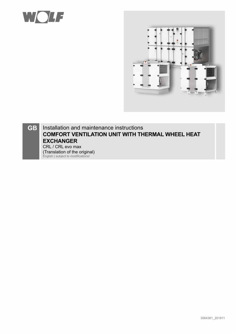
GB Installation and maintenance instructionsCOMFORT VENTILATION UNIT WITH THERMAL WHEEL HEAT EXCHANGERCRL / CRL evo max(Translation of the original)English | subject to modifications!

2 3064361_201811
Table of contentsTable of contents
1 General / Safety information ................................................................... 3
2 Standards, regulations / disposal ........................................................... 5
3 CRL-iD unit layout .................................................................................. 6
4 CRL-iD appliance versions ..................................................................... 8
5 CRL-iH unit layout .................................................................................. 9
5.1 CRL-iH evo max unit layout ...................................................................11
6 CRL-iH appliance versions ................................................................... 13
7 CRL-iDH unit layout .............................................................................. 14
8 CRL-iDH appliance versions ........................................................................16
9 CRL-A unit layout ................................................................................. 17
9.1 CRL-A evo max unit layout ................................................................... 19
10 CRL-A appliance versions .................................................................... 21
11 Delivery / Handling ............................................................................... 22
12 Unit splitting for handling purposes - CRL ............................................ 24
13 Assembly - CRL evo max ..................................................................... 29
14 Installation information for external units .............................................. 32
15 Siting .................................................................................................... 33
16 Electrical connection ............................................................................ 35
17 Commissioning .................................................................................... 37
18 Maintenance shutdown ........................................................................ 46
19 Hygiene checklist ................................................................................. 47
20 Maintenance ......................................................................................... 48
21 Notes .................................................................................................... 51
33064361_201811
General information These installation and maintenance instructions only apply to WOLF CRL / CRL evo max ventilation units. Authorised personnel should read these instructions before any commissioning or maintenance work. Comply with the specifications in this document. Installation, commissioning and maintenance work must only be carried out by trained personnel.These instructions should be considered an integral part of the unit supplied, and should always be easily accessible.Failure to observe these installation and maintenance instructions voids any WOLF GmbH warranty.
Reference symbols The following reference symbols are used in these instructions. This important information concerns personal and operational safety as well as operational reliability.
“Safety information" identifies instructions that must be observed to the letter, to prevent risks and injuries to individuals and damage to the appliance.
Danger through 'live' electrical components.Please note: Turn off the ON/OFF switch before removing the casing.
Never touch electrical components or contacts when the ON/OFF switch is in the ON position. There is a danger of electrocution, resulting in a risk to health or death.
The main terminals are 'live', even when the ON/OFF switch is in the OFF position.
"Please note" designates technical instructions which you must observe to prevent the unit malfunctioning or being damaged.
Note
Only qualified and trained personnel may be appointed for the installation, commissioning, maintenance and operation of the unit.Only qualified electricians are permitted to work on the electrical system.VDE regulations [or local regulations] and those of your local power supply utility are applicable to electrical installation work.Only operate the unit within its output range, which is stated in the technical documentation supplied by WOLF.Only operate the appliance if it is in perfect technical condition. Any faults or damage that impact or might impact upon the safety or correct function of the unit must be remedied immediately by qualified personnel.Only replace faulty components and equipment with original WOLF spare parts.
It may only be used for handling air. This air must not contain any harmful, combustible, explosive, aggressive, corrosive or otherwise dangerous substances, as these would be distributed throughout the duct system or building, where they could cause a risk to the health of, or even kill the occupants, animals or plants living there.
Note
Safety information In addition to installation and maintenance instructions, there are notes attached to the unit in the form of labels. These must also be observed.
1 General / Safety information
4 3064361_201811
1 General / safety information
Fire The unit does not present a direct risk of fire.The small numbers of seals fitted inside the unit can burn away if subjected to external influences. Wear respiratory equipment if you fight a fire. The usual extinguishing agents such as water, extinguishing foam or extinguishing powder can be used to extinguish fires. As there are only a small number of flammable seals, the level of pollutants that could be released in a fire is minimal.
Recommended temperatures The ventilation unit is designed for air intake temperatures between -20 °C and +40 °C. For safety reasons, the room temperature in technical equipment rooms must not fall below 5 °C (risk of frost) or exceed 40 °C. The unit should be operated in room conditions of between 22 °C and 28 °C at approx. 55 % relative humidity.
Other technical documents - Operating instructions WRS-K- MicroMax 370W TWHE control unit operating instructions- Wiring diagram- Configuration assistant WRS-K- Commissioning report / parameter list
Electrical connection Make the electrical connection in accordance with local regulations.
Once electrical connection work is complete, the installation must be subjected to a safety test in accordance with VDE 0701-0702 and VDE 0700 part 500, as otherwise there would be a risk of electric shock that could result in injury or death.
Before working on the unit, shut it down via the isolator.
Even when the unit has been shut down, voltage will still be present at terminals and connections of the EC fans. This means there is a risk of electric shock that could result in injury or death.Do not touch the EC fans for five minutes after disconnecting the power across all poles.
Intended use Wolf CRL / CRL evo max ventilation units are designed to heat and filter normal air. Max. Max. air intake temperature: +40 °C. The use of these units in wet rooms or rooms with explosive atmospheres is not permissible. Handling very dusty or aggressive media is not permissible.Any onsite modification or improper use of the unit is not permissible and WOLF GmbH accepts no liability for any damage caused as a result.Ventilation units intended for internal installation must be placed in rooms that meet the requirements of VDI 2050 (VDI 2050, Requirements for technical equipment rooms - Planning and execution).
In accordance with DIN 1886, tools are required to open the unit. Wait for the fan to reach standstill (2 minutes wait). When the doors are opened, negative pressure may draw in loose objects, which could destroy the fan or even cause a risk to life if items of clothing are drawn in.
Removal and disabling of safety and monitoring equipment is prohibited.The system must only be operated if it is in perfect technical condition. Ensure that any faults or damage that may impact on safety are rectified immediately.
Warnings

53064361_201811
Standards and regulations - Machinery Directive 2006/42/EC
- Low Voltage Directive 2014/35/EU
- EMC Directive 2014/30/EU
- ErP Directive 2009/125/EC
- EN ISO 12100 Safety of machinery; general principles for design
- DIN EN ISO 13857: Safety of machinery; safety distances
- DIN EN 349 Safety of machinery; minimum clearances
- DIN EN 953 Safety of machinery; Guards
- DIN EN 1886 Ventilation for buildings; central air-handling units
- DIN ISO 1940-1 Mechanical vibration; balance quality requirements
- VDMA 24167 Fans; safety requirements
- DIN EN 60204-1 Safety of machinery - Electrical equipment of machines
- DIN EN 60730 Automatic electrical controls
- DIN EN 61000 -6-2+3 Electromagnetic Compatibility
In addition, ÖVE regulations and the local building code apply to Austria.
2 Standards, regulations / disposal
The following standards and regulations apply to installation and operation:
- DIN EN 50106 (VDE 0700-500) Safety of electrical appliances; tests
- DIN VDE 0100 Regulations regarding the installation of high voltage systems up to 1000 V
- DIN EN 50110-1 (VDE 0105-1) Operation of electrical installations
- DIN VDE 0105-100 Operation of electrical systems; general stipulations
Disposal and recycling When the unit reaches the end of its service life, it must only be dismantled by qualified personnel. Before starting to dismantle the unit, disconnect the power supply. Power cables must be removed by qualified electricians. Sort and dispose of metal and plastic parts according to material types and in compliance with local regulations. Dispose of electrical and electronic components as electrical waste.
6 3064361_201811
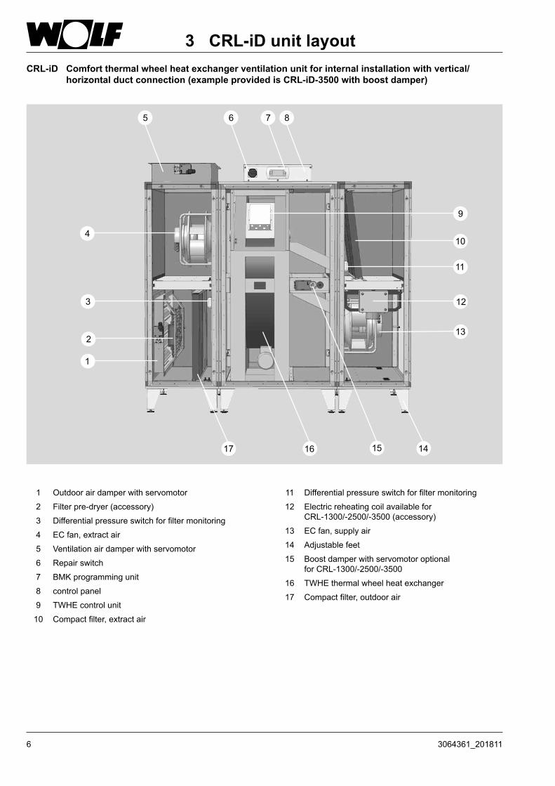
3 CRL-iD unit layoutCRL-iD Comfort thermal wheel heat exchanger ventilation unit for internal installation with vertical/
horizontal duct connection (example provided is CRL-iD-3500 with boost damper)
1 Outdoor air damper with servomotor
2 Filter pre-dryer (accessory)
3 Differential pressure switch for filter monitoring
4 EC fan, extract air
5 Ventilation air damper with servomotor
6 Repair switch
7 BMK programming unit
8 control panel
9 TWHE control unit
10 Compact filter, extract air
11 Differential pressure switch for filter monitoring
12 Electric reheating coil available for CRL-1300/-2500/-3500 (accessory)
13 EC fan, supply air
14 Adjustable feet
15 Boost damper with servomotor optional for CRL-1300/-2500/-3500
16 TWHE thermal wheel heat exchanger
17 Compact filter, outdoor air

73064361_201811
3 CRL-iD unit layout
Type CRL-iD-4800 CRL-iD-6200 CRL-iD-9000Unit layout Three piece Three piece Three pieceLength L mm 1728 1932 2136Length L1 mm 610 712 814Length L2 (rotor part) mm 508 508 508Depth D (incl. locks) mm 1360 1665 2070Total height mm 1722 1722 1925Height H mm 1424 1424 1627Foot height mm 170 170 170Control unit height mm 122 122 122Duct connection dimensions, horizontal air routing mm intl 1222 x 612 intl 1527 x 612 intl 1934 x 714
Duct connection dimensions, vertical air routing mm intl 1222 x 510 intl 1527 x 612 intl 1934 x 714
Weight kg 590 (180+230+180)
715 (220+275+220)
845 (275+295+275)
Nominal flow rate m³/h 4800 at 450 Pa (ext.) 6200 at 680 Pa (ext.) 9000 at 1000 Pa (ext.)
Type CRL-iD-1300 CRL-iD-2500 CRL-iD-3500Unit layout Single piece Single piece Three pieceLength L mm 1525 / 1525* 1626 / 1626* 1626 / 1830*Length L1 mm - - 508Length L2 (rotor part) mm - - 610 / 814*Depth D (incl. locks) mm 750 950 1155Total height mm 1315 1722 1722Height H mm 1017 1424 1424Foot height mm 170 170 170Control unit height mm 122 122 122Duct connection dimensions, horizontal air routing mm int. 612x409 Intl 815x612 Intl 1019x612
Duct connection dimensions, vertical air routing mm Intl 596x307 Intl799x307 Intl1019x408
Weight kg 266 / 266* 381 / 381*470 / 490*
(130+210+130) (130+230+130)*
Nominal flow rate m³/h 1300 at 460 Pa (ext.) 2500 at 600 Pa (ext.) 3500 at 980 Pa (ext.)* with boost damper
H
T L
170
128 122
L1L2
L1
L2*
TWHE with boost damper
1 Outdoor air2 Exhaust air
24
1 3
H Total
3 Supply air4 Extract air

8 3064361_201811
4 CRL-iD appliance versions
Access side in supply air direction, left Access side in supply air direction, right
1For CRL-1300/-2500/-3500, these versions are available with a boost damper.
11
11

93064361_201811
CRL-iH Comfort thermal wheel heat exchanger ventilation unit for internal installation with horizontal duct connection (example provided is CRL-iH-3500 with boost damper)
5 CRL-iH unit layout
1 Outdoor air damper with servomotor
2 Filter pre-dryer (accessory)
3 Differential pressure switch for filter monitoring
4 EC fan, extract air
5 Ventilation air damper with servomotor
6 Repair switch
7 BMK programming unit
8 control panel
9 TWHE control unit
10 Compact filter, extract air
11 Differential pressure switch for filter monitoring
12 Electric reheating coil available for CRL-1300/-2500/-3500 (accessory)
13 EC fan, supply air
14 Adjustable feet
15 Boost damper with servomotor optional for CRL-1300/-2500/-3500
16 TWHE thermal wheel heat exchanger
17 Compact filter, outdoor air

10 3064361_201811
Type CRL-iH-1300 CRL-iH-2500 CRL-iH-3500Unit layout Single piece Single piece Three pieceLength L mm 1525 / 1525* 1626 / 1626* 1626 / 1830*Length L1 mm - - 508Length L2 (rotor part) mm - - 610 / 814*Depth D (incl. locks) mm 750 950 1155Total height mm 1309 1716 1716Height H mm 1017 1424 1424Foot height mm 170 170 170Control unit height mm 122 122 122Duct connection dimensions, horizontal air routing mm int. 612x409 Intl 815x612 Intl 1019x612
Weight kg 266 / 266* 381 / 381*470 / 490*
(130+210+130) (130+230+130)*
Nominal flow rate m³/h 1300 at 460 Pa (ext.) 2500 at 600 Pa (ext.) 3500 at 980 Pa (ext.)* with boost damper
Type CRL-iH-4800 CRL-iH-6200 CRL-iH-9000Unit layout Three piece Three piece Three pieceLength L mm 1728 1932 2136Length L1 mm 610 712 814Length L2 (rotor part) mm 508 508 508Depth D (incl. locks) mm 1360 1665 2070Total height mm 1716 1716 1919Height H mm 1424 1424 1627Foot height mm 170 170 170Control unit height mm 122 122 122Duct connection dimensions, horizontal air routing mm intl 1222 x 612 intl 1527 x 612 intl 1934 x 714
Weight kg 590 (180+230+180)
715 (220+275+220)
845 (275+295+275)
Nominal flow rate m³/h 4800 at 450Pa (ext.) 6200 at 680Pa (ext.) 9000 at 1000Pa (ext.)
1 Outdoor air2 Exhaust air
3 Supply air4 Extract air
24
13
L2*
TWHE with boost damper
L1L2
L1
H Total
H
T L
170
122
5 CRL-iH unit layout

113064361_201811
CRL-iH evo max Comfort thermal wheel heat exchanger ventilation unit for internal installation with horizontal duct connection (example provided is CRL-iH-11000 evo max with boost damper)
1
2
3
4 5 6 7
9
8
10
12
14151618
11
13
17
1 Outdoor air damper with servomotor
2 Differential pressure switch for filter monitoring
3 Ventilation air damper with servomotor
4 EC fan, extract air
5 TWHE thermal wheel heat exchanger
6 Repair switch
7 Panel for onsite cable entry
8 Differential pressure switch for filter monitoring
9 control panel
10 Extract air filter
11 BMK programming unit
12 EC fan, supply air
13 Base frame
14 Test connector for flow rate calculation
15 Boost damper with servomotor (optional)
16 Control TWHE
17 Outdoor air filter
18 Filter pre-dryer incl. control cabinet (accessory)
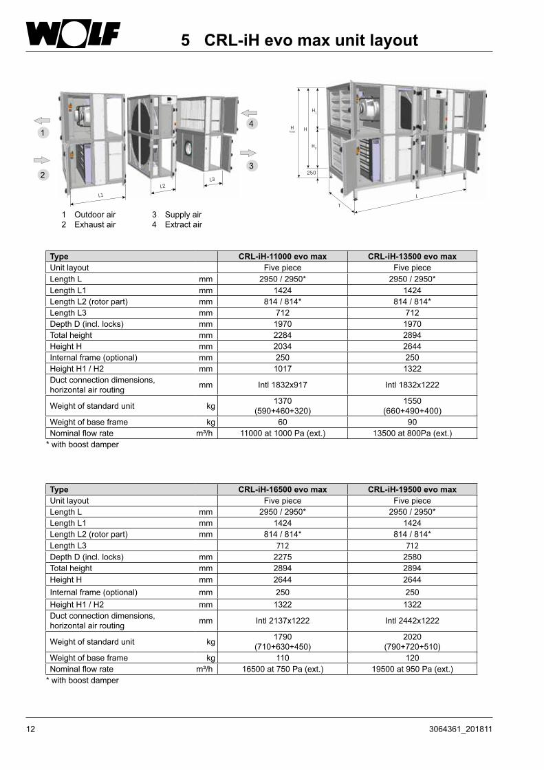
5.1 CRL-iH evo max unit layout
12 3064361_201811
L3L2
L1
H Total
H
T
L
250
H1
H2
Type CRL-iH-11000 evo max CRL-iH-13500 evo maxUnit layout Five piece Five pieceLength L mm 2950 / 2950* 2950 / 2950*Length L1 mm 1424 1424Length L2 (rotor part) mm 814 / 814* 814 / 814*Length L3 mm 712 712Depth D (incl. locks) mm 1970 1970Total height mm 2284 2894Height H mm 2034 2644Internal frame (optional) mm 250 250Height H1 / H2 mm 1017 1322Duct connection dimensions, horizontal air routing mm Intl 1832x917 Intl 1832x1222
Weight of standard unit kg 1370(590+460+320)
1550(660+490+400)
Weight of base frame kg 60 90Nominal flow rate m³/h 11000 at 1000 Pa (ext.) 13500 at 800Pa (ext.)
* with boost damper
Type CRL-iH-16500 evo max CRL-iH-19500 evo maxUnit layout Five piece Five pieceLength L mm 2950 / 2950* 2950 / 2950*Length L1 mm 1424 1424Length L2 (rotor part) mm 814 / 814* 814 / 814*Length L3 712 712Depth D (incl. locks) mm 2275 2580Total height mm 2894 2894Height H mm 2644 2644Internal frame (optional) mm 250 250Height H1 / H2 mm 1322 1322Duct connection dimensions, horizontal air routing mm Intl 2137x1222 Intl 2442x1222
Weight of standard unit kg 1790(710+630+450)
2020 (790+720+510)
Weight of base frame kg 110 120Nominal flow rate m³/h 16500 at 750 Pa (ext.) 19500 at 950 Pa (ext.)
* with boost damper
5 CRL-iH evo max unit layout
1 Outdoor air2 Exhaust air
3 Supply air4 Extract air
3
41
2
133064361_201811
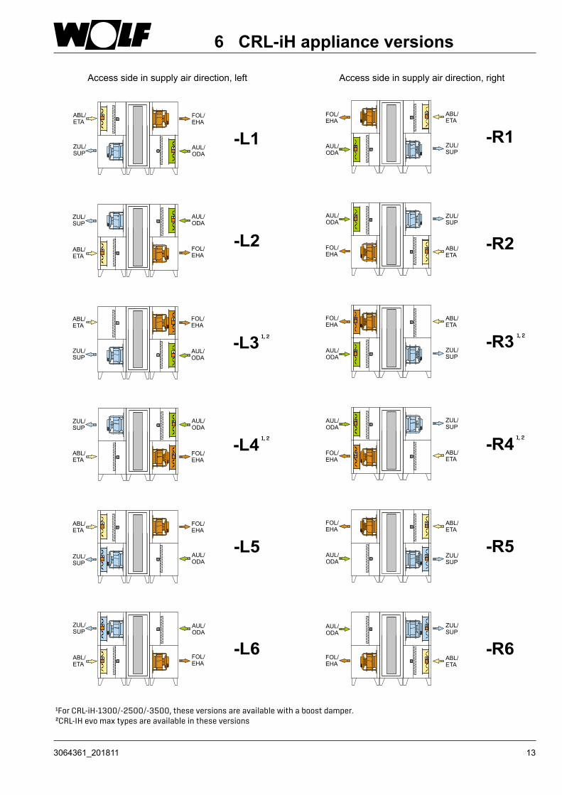
1For CRL-iH-1300/-2500/-3500, these versions are available with a boost damper. 2CRL-IH evo max types are available in these versions
Access side in supply air direction, left Access side in supply air direction, right
6 CRL-iH appliance versions
1, 2 1, 2
1, 2 1, 2

14 3064361_201811
CRL-iDH Comfort thermal wheel heat exchanger ventilation unit energy efficient and comfortable ventilation with vertical/horizontal duct connection (example provided is CRL-iDH-3500 with boost damper)
7 CRL-iDH unit layout
1 Outdoor air damper with servomotor
2 Filter pre-dryer (accessory)
3 Differential pressure switch for filter monitoring
4 EC fan, extract air
5 Ventilation air damper with servomotor
6 Repair switch
7 BMK programming unit
8 control panel
9 TWHE control unit
10 Compact filter, extract air
11 Differential pressure switch for filter monitoring
12 Electric reheating coil available for CRL-1300/-2500/-3500 (accessory)
13 EC fan, supply air
14 Adjustable feet
15 Boost damper with servomotor optional for CRL-1300/-2500/-3500
16 TWHE thermal wheel heat exchanger
17 Compact filter, outdoor air

153064361_201811
170
122
H
LT
128
H
L2*
7 CRL-iDH unit layout
Type CRL-iDH-4800 CRL-iDH-6200 CRL-iDH-9000Unit layout Three piece Three piece Three pieceLength L mm 1728 1932 2136Length L1 mm 610 712 814Length L2 (rotor part) mm 508 508 508Depth D (incl. locks) mm 1360 1665 2070Total height mm 1722 1722 1925Height H mm 1424 1424 1627Foot height mm 170 170 170Control unit height mm 122 122 122Duct connection dimensions, horizontal air routing mm intl 1222 x 612 intl 1527 x 612 intl 1934 x 714
Duct connection dimensions, vertical air routing mm intl 1222 x 510 intl 1527 x 612 intl 1934 x 714
Weight kg 590 (180 + 230 + 180)
715 (220 + 275 + 220)
845 (275 + 295 + 275)
Nominal flow rate m³/h 4800 at 450 Pa (ext.) 6200 at 680 Pa (ext.) 9000 at 1000 Pa (ext.)
Type CRL-iDH-1300 CRL-iDH-2500 CRL-iDH-3500Unit layout Single piece Single piece Three pieceLength L mm 1525 / 1525* 1626 / 1626* 1626 / 1830*Length L1 mm - - 508Length L2 (rotor part) mm - - 610 / 814*Depth D (incl. locks) mm 750 950 1155Total height mm 1315 1722 1722Height H mm 1017 1424 1424Foot height mm 170 170 170Control unit height mm 122 122 122Duct connection dimensions, horizontal air routing mm int. 612x409 Intl 815x612 Intl 1019x612
Duct connection dimensions, vertical air routing mm Intl 596x307 Intl799x307 Intl1019x408
Weight kg 266 / 266* 381 / 381*470 / 490*
(130+210+130) (130+230+130)*
Nominal flow rate m³/h 1300 at 460 Pa (ext.) 2500 at 600 Pa (ext.) 3500 at 980 Pa (ext.)* with boost damper
TWHE with boost damper1 Outdoor air
2 Exhaust air
L1L2
L1
2 4
1
3
3 Supply air4 Extract air
H Total
16 3064361_201811
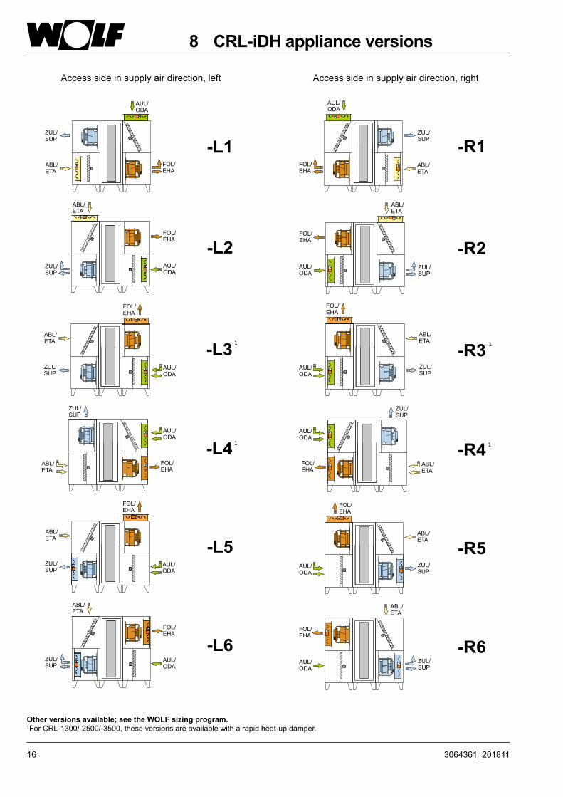
Other versions available; see the WOLF sizing program.1For CRL-1300/-2500/-3500, these versions are available with a rapid heat-up damper.
Access side in supply air direction, left Access side in supply air direction, right
8 CRL-iDH appliance versions
1 1
1 1

173064361_201811
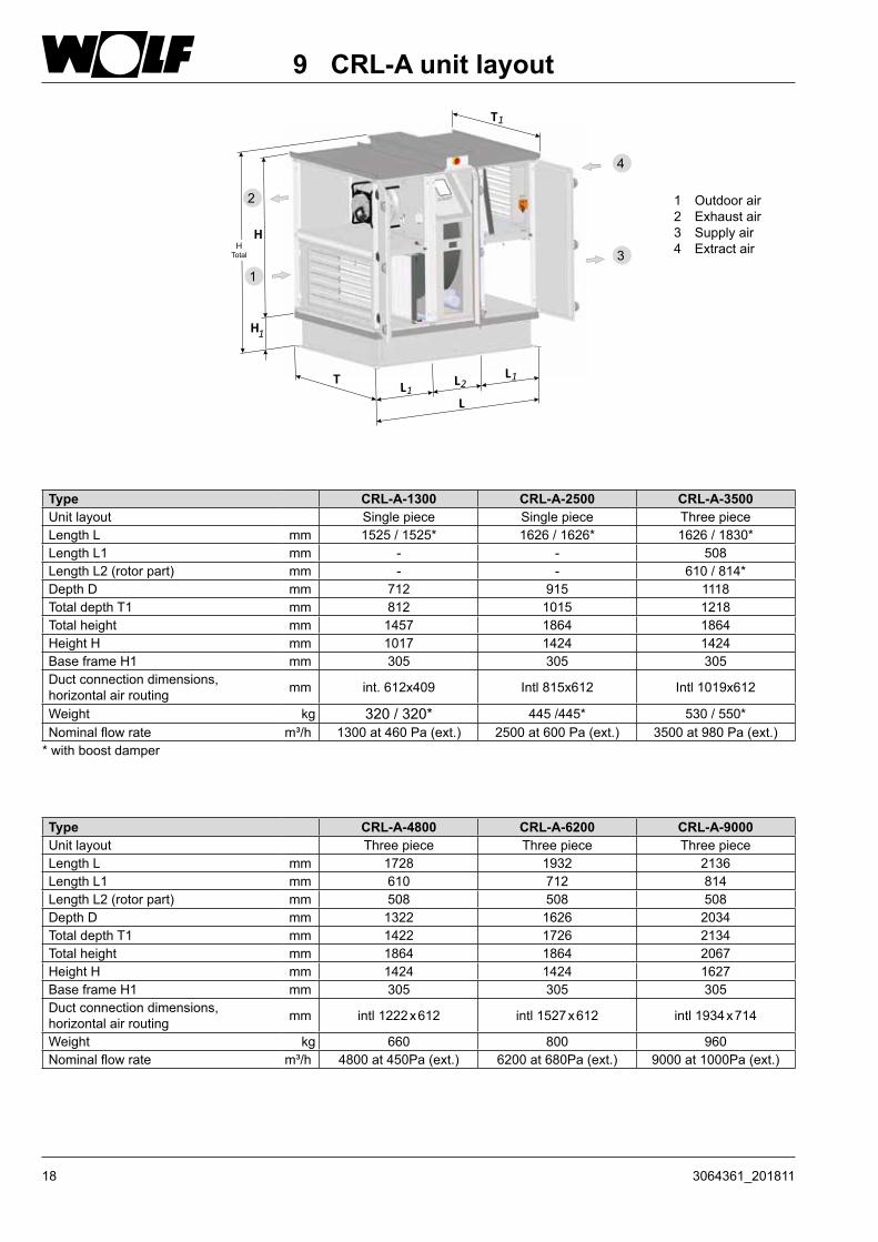
CRL-A Comfort thermal wheel heat exchanger ventilation unit for external installation (weather-resistant) with horizontal duct connection (example provided is CRL-A-3500 with boost damper)
9 CRL-A unit layout
1 Outdoor air damper with servomotor
2 Filter pre-dryer (accessory)
3 Differential pressure switch for filter monitoring
4 EC fan, extract air
5 Ventilation air damper with servomotor
6 Repair switch
7 control panel
8 TWHE control unit
9 Compact filter, extract air
10 Differential pressure switch for filter monitoring
11 Electric reheating coil available for CRL-1300/-2500/-3500 (accessory)
12 EC fan, supply air
13 Base frame
14 Boost damper with servomotor optional for CRL-1300/-2500/-3500
15 TWHE thermal wheel heat exchanger
16 Compact filter, outdoor air
17 Connectors for DN 50 trap
18 3064361_201811
9 CRL-A unit layout
H
L
T
T1
H1
L2L1
L1
Type CRL-A-1300 CRL-A-2500 CRL-A-3500Unit layout Single piece Single piece Three pieceLength L mm 1525 / 1525* 1626 / 1626* 1626 / 1830*Length L1 mm - - 508Length L2 (rotor part) mm - - 610 / 814*Depth D mm 712 915 1118Total depth T1 mm 812 1015 1218Total height mm 1457 1864 1864Height H mm 1017 1424 1424Base frame H1 mm 305 305 305Duct connection dimensions, horizontal air routing mm int. 612x409 Intl 815x612 Intl 1019x612
Weight kg 320 / 320* 445 /445* 530 / 550*Nominal flow rate m³/h 1300 at 460 Pa (ext.) 2500 at 600 Pa (ext.) 3500 at 980 Pa (ext.)
* with boost damper
Type CRL-A-4800 CRL-A-6200 CRL-A-9000Unit layout Three piece Three piece Three pieceLength L mm 1728 1932 2136Length L1 mm 610 712 814Length L2 (rotor part) mm 508 508 508Depth D mm 1322 1626 2034Total depth T1 mm 1422 1726 2134Total height mm 1864 1864 2067Height H mm 1424 1424 1627Base frame H1 mm 305 305 305Duct connection dimensions, horizontal air routing mm intl 1222 x 612 intl 1527 x 612 intl 1934 x 714
Weight kg 660 800 960Nominal flow rate m³/h 4800 at 450Pa (ext.) 6200 at 680Pa (ext.) 9000 at 1000Pa (ext.)
1 Outdoor air2 Exhaust air3 Supply air4 Extract air
2
4
13
H Total

193064361_201811
CRL-A evo max Comfort thermal wheel heat exchanger ventilation unit for external installation (weather-resistant) with horizontal duct connection (example provided is CRL-A-11000 with boost damper)
9.1 CRL-A evo max unit layout
2
4
5
7 8 9 10
12
11
13
14
161718
15
19
3
6
1
2021
1 Condensate pan
2 Intake hood with mist eliminator
3 Outdoor air damper with servomotor
4 Differential pressure switch for filter monitoring
5 Intake hood
6 Ventilation air damper with servomotor
7 EC fan, extract air
8 TWHE thermal wheel heat exchanger
9 Repair switch
10 Panel for onsite cable bushing
11 Differential pressure switch for filter monitoring
12 control panel
13 Extract air filter
14 EC fan, supply air
15 Base frame
16 Test connector for flow rate calculation
17 Boost damper with servomotor (optional)
18 TWHE control unit
19 Outdoor air filter
20 Filter pre-dryer incl. control cabinet (accessory)
21 Connectors for R 11/4 trap

20 3064361_201811
L2L3
300
H Total
H
T L
H1
H2
T1
180L1
9 CRL-A evo max unit layout
Type CRL-A-11000 evo max CRL-A-13500 evo maxUnit layout Five piece Five pieceLength L mm 2950 / 2950* 2950 / 2950*Length L1 mm 1424 1424Length L2 (rotor part) mm 814 / 814* 814 / 814*Length L3 mm 712 712Depth D mm 1932 1932Depth T1 (incl. roof overhang) mm 2032 2032H1 / H2 mm 1017 1322Total height mm 2214 2824Height H mm 2034 2644Base frame height mm 180 180Duct connection dimensions, horizontal air routing mm Intl 1832x917 Intl 1832x1222
Weight of standard unit kg 1520(710+470+340)
1720(810+510+400)
Weight of base frame kg 100 100Nominal flow rate m³/h 11000 at 1000 Pa (ext.) 13500 at 800 Pa (ext.)
* with boost damper
Type CRL-A-16500 evo max CRL-A-19500 evo maxUnit layout Five piece Five pieceLength L mm 2950 / 2950* 2950 / 2950*Length L1 mm 1424 1424Length L2 (rotor part) mm 814 / 814* 814 / 814*Length L3 mm 712 712Depth D mm 2237 2542Depth T1 (incl. roof overhang) mm 2337 2642H1 / H2 mm 1322 1322Total height mm 2824 2824Height H mm 2644 2644Base frame height mm 180 180Duct connection dimensions, horizontal air routing mm Intl 2137x1222 Intl 2442x1222
Weight of standard unit kg 1990 (890+640+460)
2260 (990+750+520)
Weight of base frame kg 110 120Nominal flow rate m³/h 16500 at 750 Pa (ext.) 19500 at 950 Pa (ext.)
* with boost damper
1 Outdoor air2 Exhaust air
3 Supply air4 Extract air
3
42
1

213064361_201811
Access side in supply air direction, left Access side in supply air direction, right
10 CRL-A appliance versions
1For CRL-A-1300/-2500/-3500, these versions are available with a boost damper.2 CRL-A evo max types are available in these versions3 These versions are only available for CRL-A evo max units
ZUL/
SUP
ABL/
ETA
AUL/
ODA
FOL/
EHA
-L1
ABL/
ETA
ZUL/
SUP
FOL/
EHA
AUL/
ODA
-L3
ABL/
ETA
ZUL/
SUP
FOL/
EHA
AUL/
ODA
-L5
ABL/
ETA
ZUL/
SUP
FOL/
EHA
AUL/
ODA
-L4
ZUL/
SUP
ABL/
ETA
AUL/
ODA
FOL/
EHA
FOL/
EHA
AUL/
ODA
ABL/
ETA
ZUL/
SUP
FOL/
EHA
AUL/
ODA
ABL/
ETA
ZUL/
SUP
FOL/
EHA
AUL/
ODA
ABL/
ETA
ZUL/
SUP
-R1
-R3
-R5
-R4
1, 2 1, 2
3 3

22 3064361_201811
11 Delivery / Handling
Delivery CRL / CRL evo max ventilation units are supplied in packaging that protects them from dirt and damage. Upon receipt of the goods, check the unit for possible transport damage. If there is any damage or even a suspicion of damage, the recipient must indicate this on the consignment note and have it countersigned by the haulier. The recipient of the goods must notify WOLF of the relevant facts without delay.Dispose of the transport packaging in accordance with local regulations.
Storage Only store the ventilation unit in dry rooms at an ambient temperature between -25 °C and +55 °C. If it is stored for a long time, ensure that all apertures are sealed against air and water ingress.
Delivered condition
General handling information Units are supplied fully assembled and fully wired.Only transport units in their installation position. Never tilt the unit when transporting it through doorways or in narrow stairwells (lifts).Failure to observe these instructions can damage internal components irreparably.

233064361_201811
11 Delivery/HandlingTransport ropes with a minimum length equivalent to the eye bolt distance L must be used when transporting external CRL units with eye bolts. The same applies to the individual transport units of the CRL evo max units.External CRL evo max units may only be lifted as an entire unit with a lifting beam when pulling equally and vertically on all available eye bolts.
Unit connector
Control unit cover
The 3500, 4800, 6200 and 9000 versions of the CRL internal units can be split into three sections for easier handling. (Delivered as a transport unit)CRL evo max internal units are delivered in 3 transport units as standard. The procedure for connecting the units together is described in Item 13.Unit connectors, hexagon bolts and nuts are used to connect the parts together. Electric lines and control cables can be disconnected and connected again quite simply by means of plug-in connections in the control unit casing.
Transport external units
Transport Internal units
Lifting beam
90° 90°
113,6
1m
m
L
max. 60°
Min. L
24 3064361_201811
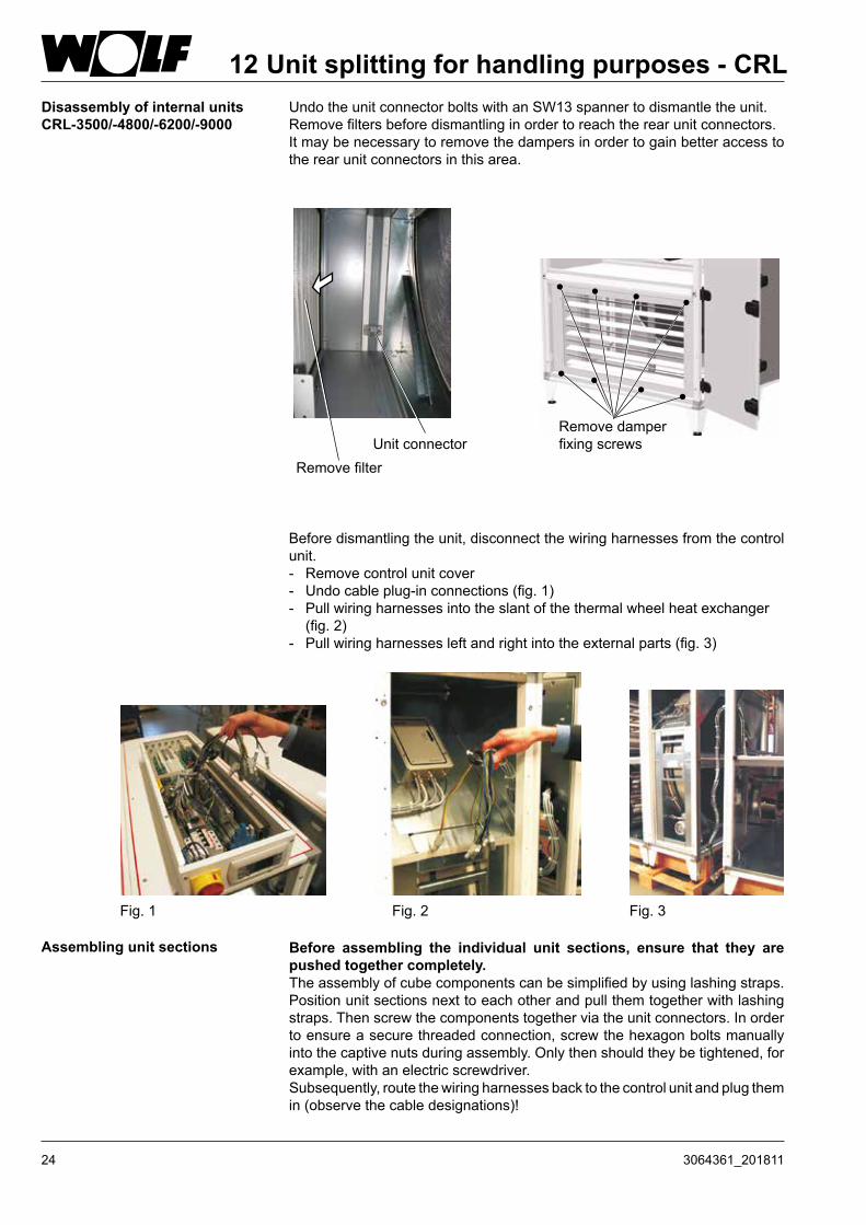
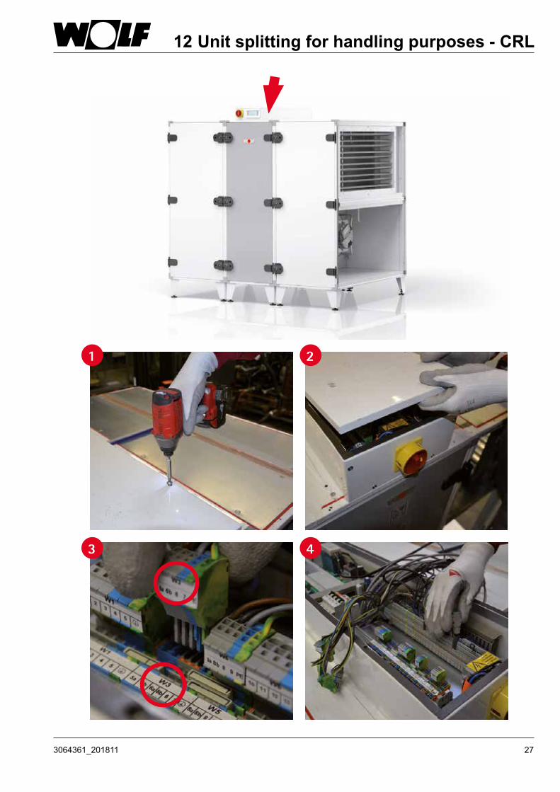
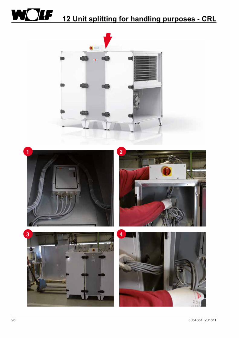
12 Unit splitting for handling purposes - CRL
Assembling unit sections Before assembling the individual unit sections, ensure that they are pushed together completely.The assembly of cube components can be simplified by using lashing straps. Position unit sections next to each other and pull them together with lashing straps. Then screw the components together via the unit connectors. In order to ensure a secure threaded connection, screw the hexagon bolts manually into the captive nuts during assembly. Only then should they be tightened, for example, with an electric screwdriver.Subsequently, route the wiring harnesses back to the control unit and plug them in (observe the cable designations)!
Remove damper fixing screws
Undo the unit connector bolts with an SW13 spanner to dismantle the unit.Remove filters before dismantling in order to reach the rear unit connectors.It may be necessary to remove the dampers in order to gain better access to the rear unit connectors in this area.
Unit connectorRemove filter
Before dismantling the unit, disconnect the wiring harnesses from the control unit.- Remove control unit cover - Undo cable plug-in connections (fig. 1)- Pull wiring harnesses into the slant of the thermal wheel heat exchanger
(fig. 2)- Pull wiring harnesses left and right into the external parts (fig. 3)
Fig. 1 Fig. 2 Fig. 3
Disassembly of internal unitsCRL-3500/-4800/-6200/-9000

253064361_201811
1 2
3 4
12 Unit splitting for handling purposes - CRL

26 3064361_201811
1 2
3 4
12 Unit splitting for handling purposes - CRL
273064361_201811
1 2
3 4
12 Unit splitting for handling purposes - CRL
28 3064361_201811
1 2
3 4
12 Unit splitting for handling purposes - CRL

293064361_201811
13 Assembly - CRL evo max
4x
A1
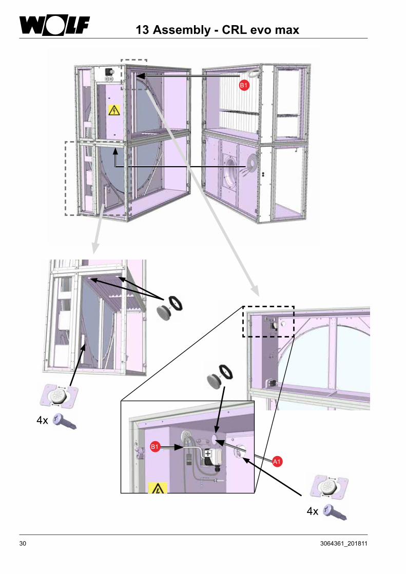
30 3064361_201811
13 Assembly - CRL evo max
4x
4x
B1
B1
A1

313064361_201811
13 Assembly - CRL evo max

32 3064361_201811
Weatherproof units must not be used for any load-bearing building functions or as a replacement for any part of the roof (VDI 3803 5.1 / DIN EN 13053 6.2).
A level, horizontal load-bearing surface is required for siting and installing the external units.
Base frames must be levelled horizontally (check with a spirit level).
To prevent the inspection doors from jamming, the entire base frame must sit on the foundation; point loads are not permissible.
To prevent structure-borne noise transmission from the CRL to the building, insert a permanently flexible intermediate layer between the foundation and the base frame. This intermediate layer should preferably take the form of insulation strips, fitted lengthwise below the base frame.
The WOLF base frame and its integration into the roof membrane must be insulated onsite.
In the case of elevated positioning (CRL on onsite framework), the CRL must be secured against wind load.
14 Installation information for external units
Insulation(if required)Insulation against structure- borne noise
Insulation against structure-borne noise
Roof seal

333064361_201811
15 SitingMinimum clearance between outdoor air intake and exhaust air aperture to prevent an "air short circuit" (DIN 13779)
Exhaust air
Exhaust air
Outdoor air
Outdoor air
Extract airSupply air
Functional illustration of air inflow:CRL-iD
Functional illustration of air inflow:CRL-iH
Extract airSupply air
Exhaust air
Exhaust air
Outdoor air
Outdoor air
Extract air
Extract air
Supply air
Supply air
Exhaust air
Outdoor air Extract
air
Supply air
34 3064361_201811
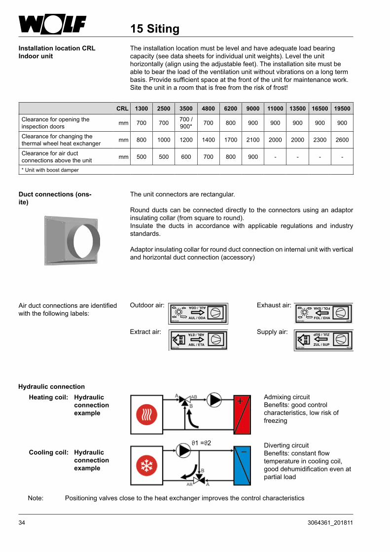
15 SitingInstallation location CRLIndoor unit
The installation location must be level and have adequate load bearing capacity (see data sheets for individual unit weights). Level the unit horizontally (align using the adjustable feet). The installation site must be able to bear the load of the ventilation unit without vibrations on a long term basis. Provide sufficient space at the front of the unit for maintenance work.Site the unit in a room that is free from the risk of frost!
Duct connections (ons-ite)
The unit connectors are rectangular.
Round ducts can be connected directly to the connectors using an adaptor insulating collar (from square to round).Insulate the ducts in accordance with applicable regulations and industry standards.
Adaptor insulating collar for round duct connection on internal unit with vertical and horizontal duct connection (accessory)
Outdoor air:
AUL / ODA6801059 48/10
AUL/ODA Exhaust air:
FOL / EHA6801062 48/10
FOL/EHA
Extract air:
ABL / ETA
ABL/ETA
6801061 48/10
Supply air:
ZUL / SUP6801060 48/10
ZUL/SUP
Air duct connections are identified with the following labels:
Hydraulic connectionHeating coil: Hydraulic
connection example
Cooling coil: Hydraulic connection example
Admixing circuitBenefits: good control characteristics, low risk of freezing
Diverting circuitBenefits: constant flow temperature in cooling coil, good dehumidification even at partial load
Note: Positioning valves close to the heat exchanger improves the control characteristics
ϑ1 =ϑ2
CRL 1300 2500 3500 4800 6200 9000 11000 13500 16500 19500
Clearance for opening the inspection doors mm 700 700 700 /
900* 700 800 900 900 900 900 900
Clearance for changing the thermal wheel heat exchanger mm 800 1000 1200 1400 1700 2100 2000 2000 2300 2600
Clearance for air duct connections above the unit mm 500 500 600 700 800 900 - - - -
* Unit with boost damper

353064361_201811
16 Electrical connectionElectrical connection The electrical connection may only be made by electricians in accordance with
local regulations.When connecting the control unit and control accessories, observe the instructions and wiring diagrams provided.Once electrical connection work is complete, the installation must be subjected to a safety test in accordance with VDE 0701-0702 and VDE 0700 part 500, as otherwise there would be a risk of electric shock that could result in injury or death.
Before working on the unit, shut it down via the isolator.The control panel has cable entries for connecting the onsite cables.
Size
Standard units withoutIntegral Elec. heating coil
Standard units withIntegral Elec. heating coil
Power cable Onsite fuse/MCB Power cable Onsite fuse/
MCBCRL-1300 3 x 1.5 mm² 16 A 5 x 1.5 mm² 10 A
CRL-2500 5 x 1.5 mm² 16 A 5 x 2.5 mm² 20 A
CRL-3500 5 x 2.5 mm² 20 A 5 x 6.0 mm² 35 A
CRL-4800 5 x 2.5 mm² 20 A - -
CRL-6200 5 x 4.0 mm². 25 A - -
CRL-9000 5 x 6.0 mm² 35 A - -
CRL-11000 5 x 4.0 mm². 25 A - -
CRL-13500 5 x 6.0 mm² 35 A - -
CRL-16500 5 x 6.0 mm² 35 A - -
CRL-19500 5 x 10 mm². 50 A - -
Even when the unit has been shut down, voltage will still be present at terminals and connections of the EC fans. This means there is a risk of electric shock that could result in injury or death.Do not touch the EC fans for five minutes after disconnecting the power across all poles.
Use a rubber mat if working on the unit when it is electrically charged.Only use cables that meet local wiring regulations with regard to voltage, current, insulation material, load etc. Always fit an earth conductor.
RCDsOnly AC/DC-sensitive fault current safety devices, type B, with 300 mA are permissible. There is no personal safety protection if the unit is operated with RCDs.Regularly check the perfect function of all electrical equipment.Observe the specified electrical fuse/MCB protection ratings.Any damage or loss resulting from technical modifications to WOLF control units is excluded from our warranty.
Inlet for onsite cables
Entry for onsite cables
CRL
CRL evo max

36 3064361_201811
16 Electrical connection
Size Rated voltage max. Fan power consumption
max. Current consumption
fansFan speed IP rating /
protection class
CRL-1300 1 x 230V (50/60Hz) 1.0kW 4.6A 3080 rpm IP55 / Iso F
CRL-2500 3 x 400V (50/60Hz) 2.1kW 3.2A 3400 rpm IP55 / Iso F
CRL-3500 3 x 400V (50/60Hz) 5.0kW 8.0A 2970 rpm IP 54 / Iso F
CRL-4800 3 x 400V (50/60Hz) 3.4kW 5.2A 2600 rpm IP 54 / Iso F
CRL-6200 3 x 400V (50/60Hz) 6.0kW 9.2A 2550 rpm IP 54 / Iso F
CRL-9000 3 x 400V (50/60Hz) 11.0kW 17A 2200 rpm IP 54 / Iso F
CRL-11000 3 x 400V (50/60Hz) 11.4kW 18A 2250 rpm IP 54 / Iso F
CRL-13500 3 x 400V (50/60Hz) 14.4kW 23.2A 2260 rpm IP 54 / Iso F
CRL-16500 3 x 400V (50/60Hz) 13.8kW 21.2A 1910 rpm IP 54 / Iso F
CRL-19500 3 x 400V (50/60Hz) 21.6kW 34.4A 2130 rpm IP 54 / Iso F

373064361_201811
17 Commissioning Commissioning and maintenance work must only be carried out by trained personnel.
Only work on the unit with it being at zero volt.
According to EN 50110-1, only qualified electricians may carry out the installation and commissioning of the ventilation control unit and connected accessories.
Observe all local EMC regulations and all VDE regulations.
DIN VDE 0100 regulations regarding the installation of high voltage systems up to 1000 V
DIN VDE 0105-100 Operation of electrical systems
Only original WOLF accessories may be used (electric coils, servomotors, etc.), otherwise WOLF cannot accept any liability.
In addition, ÖVE regulations and the local building code apply to Austria.
Before commissioning, check whether the operating data on the type plate is adhered to.
The unit must not be operated before all necessary safety equipment has been fitted and connected. Intake and discharge apertures must be connected to ensure contact protection.
The unit must be level and safely secured.
Commissioning must be carried out by authorised personnel (WOLF service).
Record the date of commissioning, e.g. in a log book.
In accordance with DIN 1886, tools are required to open the unit. Wait for the fans to come to a complete standstill before opening the inspection doors. When opening the doors, negative pressure may draw in loose objects, which could damage the fan irreparably or even cause a risk to life if items of clothing are drawn in. Use tools to tightly seal the doors before commissioning (unit tightness).
Connect the power cable and accessories in accordance with the wiring diagram provided.
A high leakage current can be expected due to the EC motors. Ensure that a secure earth connection is in place before connecting the power supply and commencing commissioning.
If control voltage is present or a set speed is saved, the EC fans will restart automatically after power failure.
- Switch ON the unit isolator.
- Wait until the BMK programming unit initialises and switches to display mode.
- Select the required operating mode at the BMK; the system will start with the preset parameters.
- To modify functions and parameters, see the installation and operating instructions provided.
Commissioning Procedure
Commissioning regulations

38 3064361_201811
Fans
Note
Use tools to tightly seal the doors before commissioning (unit tightness), otherwise there is a risk of motor overload.
Carry out air flow rate tests with the doors closed.Route test hose connections out of the unit (see flow rate calculation).Changes are made via the BMK programming unit (see relevant operating instructions).
Where the system is not commissioned by WOLF, check all inputs and outputs for correct wiring and function.- Frost protection function- Fan rotational direction- Outdoor air/extract air damper rotational direction- Plausible sensor values (room sensor, supply air sensor, extract air sensor,
outdoor air sensor)- Check motor currents- Motor protection (thermal cut-outs / thermistors)- Air flow monitoring- Filter monitor- Actuator, heating / cooling- Heating circuit pump / cooling circuit pump- As well as all other system-specific functions
The WOLF warranty will be void if the function test is not carried out correctly.
Filter pre-dryer (accessory) To prevent the electric heating coil from switching off, never operate the CRL below its minimum air flow rate. Follow the relevant safety regulations for electric heating coils.The electric heating coil must be protected from moisture and water.The filter pre-dryer starts automatically at outside temperatures below 5 °C.
Type CRL 1300 2500 3500 4800 6200 9000
Recomm. Minimum air volume m³/h 600 1200 1800 2400 3100 4500
Type CRL evo max 11000 13500 16500 19500
Recomm. Minimum air volume m³/h 5500 6500 8000 9500
17 Commissioning

393064361_201811
Condensate pan Provide a trap for the condensate drain and route the condensate into the sewerage system.Protect the condensate drain from frost.Fill the trap with water.
Trap The effective height of the trap h (mm) must exceed the maximum underpressure or overpressure at the condensate connector (1mm WC = 10Pa).
h = 1.5 x p (mmWC) + 50 mm (min.)
p = Under- or overpressure in mmWC according to appliance design 50 mm (WC) = Reserve (imprecision in design, evaporation) 1.5 = Additional Safety factor
The trap drain line must not be connected directly to the public sewage system, but rather must be able to run out freely. Vent longer drain lines to prevent condensate backing up in the line (provide additional vent in trap drain line).
Electric reheating coil (accessory) To prevent the electric heating coil from switching off, never operate the CRL below its minimum air flow rate. Follow the relevant safety regulations for electric heating coils.The electric heating coil must be protected from moisture and water.
Type CRL 1300 2500 3500
Recomm. Minimum air volume m³/h 600 1200 1800
h
17 Commissioning

40 3064361_201811
The MicroMax 370W rotor control unit includes the following functions:- Automatic interval mode- Variable speed control- Acceleration and deceleration ramp- Motor brake on standstill- Rotation monitor with rotation sensor- Alarm relay- Test switch
In principle, the thermal wheel heat exchanger is maintenance-free.The rotational direction of the TWHE has no effect on heat recovery. When the TWHE control unit is switched off, interval mode ensures further rotation in order to prevent fin soiling.
Layout and function of the TWHE control unit
Rotor control unit
Rotor motor
A rotating cylinder mass (rotor material corrosion-resistant aluminium alloy, wound in corrugated and smooth layers) absorbs heat from the extract air flow and transfers it to the outdoor air. The rotor mass is sealed by a circumferential labyrinth seal. Output is controlled by varying the speed of the drive motor. Force is transmitted from the motor to the rotor by a circumferential V-belt. There is no need for frost protection, a defrosting device or air preheating.
Heat recovery function with thermal wheel heat exchanger
100 % of the extract air flows over the rapid heat-up damper and is routed directly back into the room. In order to achieve the required set room temperature as quickly as possible, the air temperature is raised to a maximum via a reheating coil.In this operating mode, the ODA and EHA dampers are completely closed; the ETA fan and heat recovery (TWHE) are not operational. The SUP fan is running and delivers the required flow rate.When the set room temperature has been achieved, the unit switches back into standard control mode.
17 Commissioning
Function for modeQuick heat-up(optional for CRL-1300/-2500/-3500and CRL evo max units)

413064361_201811
Flow rate calculation
V = k √Dpw
V in [m³/h] and Dpw in [Pa]
The flow rate is calculated using the effective pressure method. This involves comparing the static pressure upstream of the inlet nozzle with the static pressure in the inlet nozzle.The flow rate can be calculated from the effective pressure Δp w (differential pressure of the two static pressures) using the following equation.The doors must be closed to determine the correct flow rate. Guide the test hoses over the test connectors towards the outside.
CRL-1300 effective pressure
Δp [Pa] 43 62 85 111 140 173 209 249 293
V [m³/h] 500 600 700 800 900 1000 1100 1200 1300
The fans used for the CRL-1300 have a k value of 76.
Effe
ctiv
e pr
essu
re Δ
p [P
a]
Flow rate [m³/h]
Δp = effective pressure(symbolic representation)
20.0
70.0
120.0
170.0
220.0
270.0
320.0
450 550 650 750 850 950 1050 1150 1250 1350
V = 76 x √Dpw
CRL-2500 effective pressure The fans used for the CRL-2500 have a k value of 77.
Effe
ctiv
e pr
essu
re Δ
p [P
a]
Flow rate [m³/h]
Δp = effective pressure(symbolic representation)
110.0
210.0
310.0
410.0
510.0
610.0
710.0
810.0
910.0
1010.0
1110.0
850 1050 1250 1450 1650 1850 2050 2250 2450 2650
Δp [Pa] 137 204 285 379 487 609 744 892 1054
V [m³/h] 900 1100 1300 1500 1700 1900 2100 2300 2500
V = 77 x √Dpw
17 Commissioning

42 3064361_201811
CRL-3500 effective pressure
Δp [Pa] 197 247 301 361 427 498 574 656 744 837
V [m³/h] 1700 1900 2100 2300 2500 2700 2900 3100 3300 3500
The fans used for the CRL-3500 have a k value of 121.
Effe
ctiv
e pr
essu
re Δ
p [P
a]
Flow rate [m³/h]
Δp = effective pressure(symbolic representation)
150.0
250.0
350.0
450.0
550.0
650.0
750.0
850.0
950.0
1500 1700 1900 2100 2300 2500 2700 2900 3100 3300 3500 3700
V = 121 x √Dpw
CRL-4800 effective pressure The fans used for the CRL-4800 have a k value of 148.
Effe
ctiv
e pr
essu
re Δ
p [P
a]
Flow rate [m³/h]
Δp = effective pressure(symbolic representation)
160.0
260.0
360.0
460.0
560.0
660.0
760.0
860.0
960.0
1060.0
1160.0
2000 2500 3000 3500 4000 4500 5000
Δp [Pa] 201 263 333 411 497 592 694 805 924 1052
V [m³/h] 2100 2400 2700 3000 3800 3600 3900 4200 4500 4800
V = 148 x √Dpw
17 Commissioning
433064361_201811
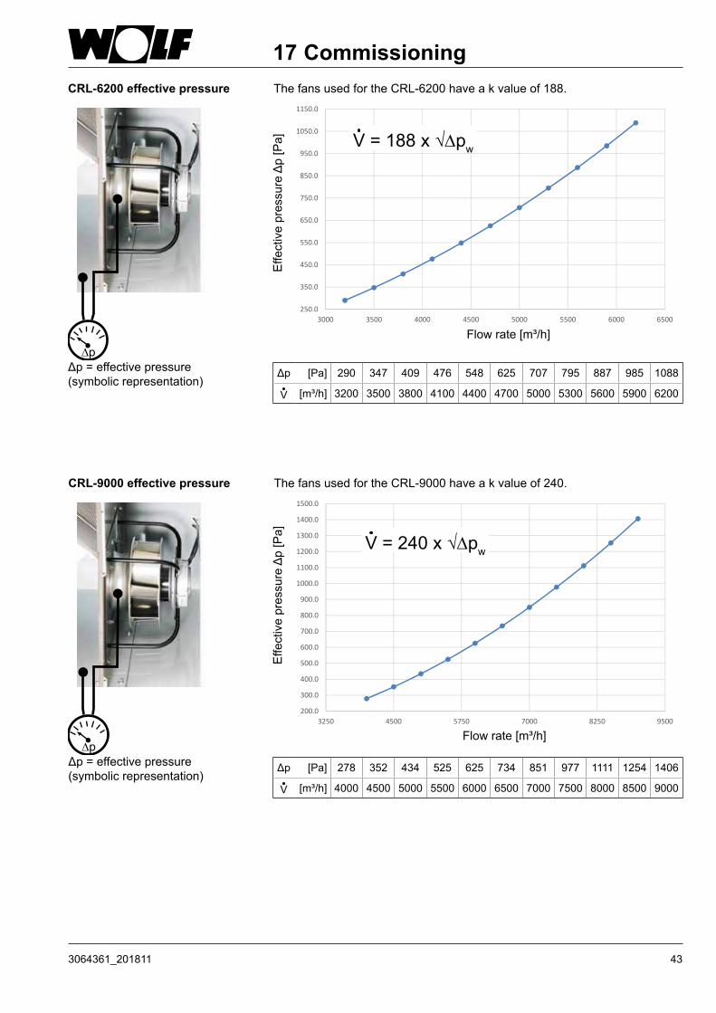
CRL-6200 effective pressure The fans used for the CRL-6200 have a k value of 188.
Effe
ctiv
e pr
essu
re Δ
p [P
a]
Flow rate [m³/h]
Δp = effective pressure(symbolic representation)
Δp [Pa] 290 347 409 476 548 625 707 795 887 985 1088
V [m³/h] 3200 3500 3800 4100 4400 4700 5000 5300 5600 5900 6200
250.0
350.0
450.0
550.0
650.0
750.0
850.0
950.0
1050.0
1150.0
3000 3500 4000 4500 5000 5500 6000 6500
V = 188 x √Dpw
CRL-9000 effective pressure The fans used for the CRL-9000 have a k value of 240.
Δp = effective pressure(symbolic representation)
Effe
ctiv
e pr
essu
re Δ
p [P
a]
Flow rate [m³/h]
200.0
300.0
400.0
500.0
600.0
700.0
800.0
900.0
1000.0
1100.0
1200.0
1300.0
1400.0
1500.0
3250 4500 5750 7000 8250 9500
V = 240 x √Dpw
Δp [Pa] 278 352 434 525 625 734 851 977 1111 1254 1406
V [m³/h] 4000 4500 5000 5500 6000 6500 7000 7500 8000 8500 9000
17 Commissioning
44 3064361_201811
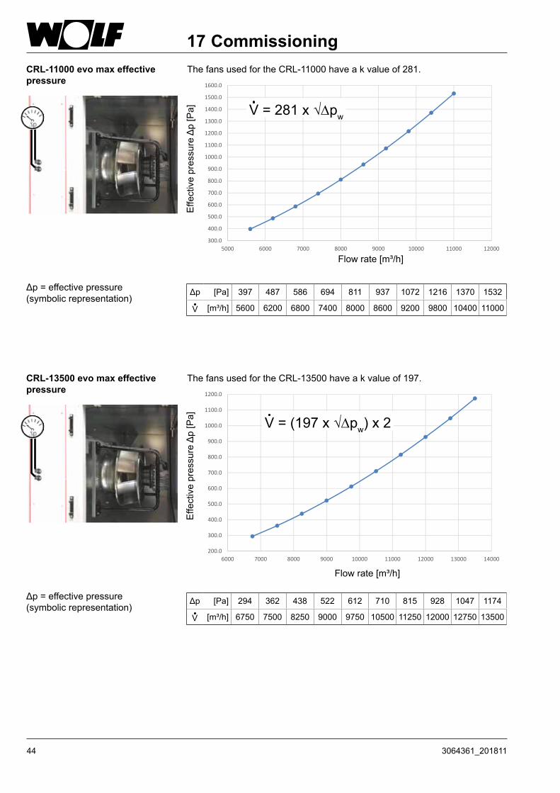
CRL-11000 evo max effective pressure
The fans used for the CRL-11000 have a k value of 281.
Effe
ctiv
e pr
essu
re Δ
p [P
a]
Flow rate [m³/h]
Δp = effective pressure(symbolic representation)
Δp [Pa] 397 487 586 694 811 937 1072 1216 1370 1532
V [m³/h] 5600 6200 6800 7400 8000 8600 9200 9800 10400 11000
300.0
400.0
500.0
600.0
700.0
800.0
900.0
1000.0
1100.0
1200.0
1300.0
1400.0
1500.0
1600.0
5000 6000 7000 8000 9000 10000 11000 12000
V = 281 x √Dpw
CRL-13500 evo max effective pressure
The fans used for the CRL-13500 have a k value of 197.
Δp = effective pressure(symbolic representation)
Effe
ctiv
e pr
essu
re Δ
p [P
a]
Flow rate [m³/h]
200.0
300.0
400.0
500.0
600.0
700.0
800.0
900.0
1000.0
1100.0
1200.0
6000 7000 8000 9000 10000 11000 12000 13000 14000
Δp [Pa] 294 362 438 522 612 710 815 928 1047 1174
V [m³/h] 6750 7500 8250 9000 9750 10500 11250 12000 12750 13500
17 Commissioning
V = (197 x √Dpw) x 2
453064361_201811
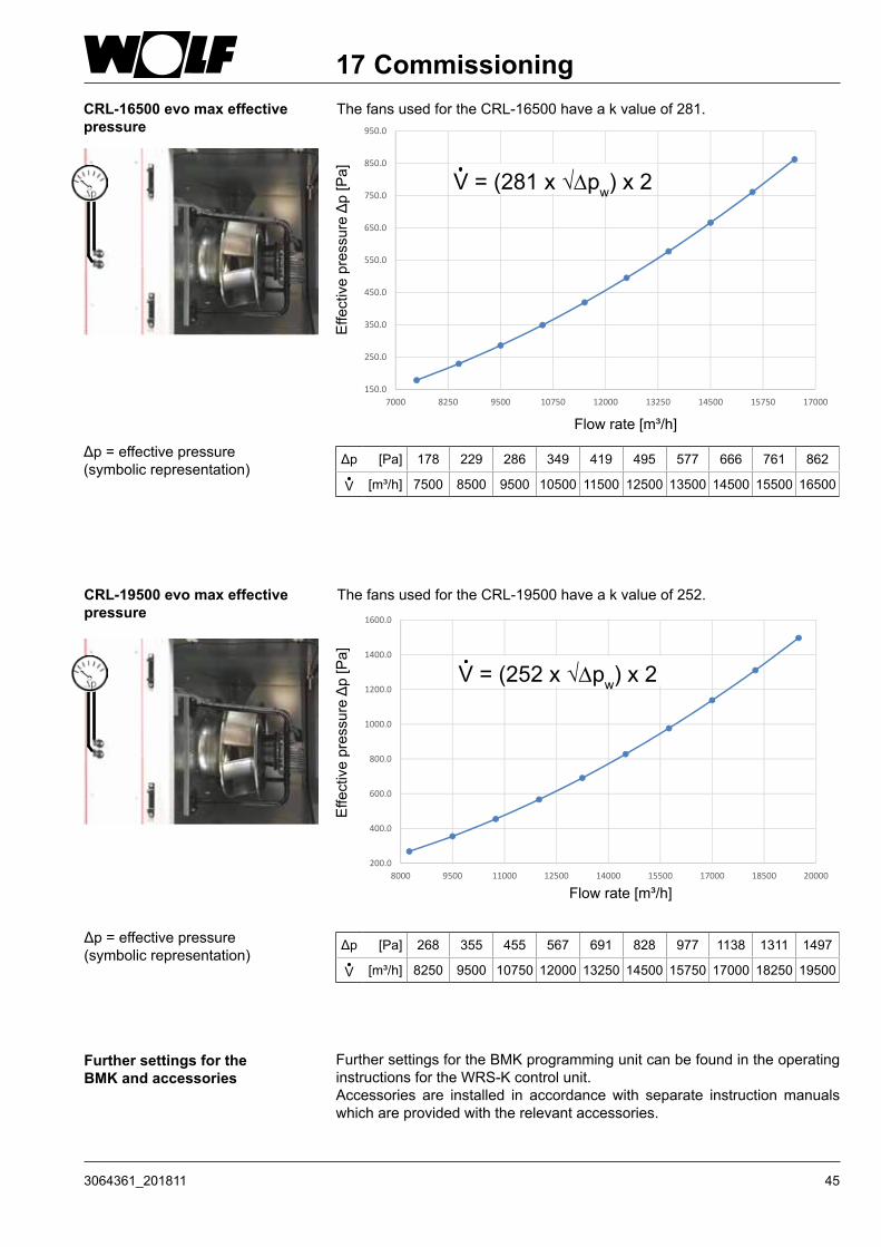
CRL-16500 evo max effective pressure
The fans used for the CRL-16500 have a k value of 281.
Effe
ctiv
e pr
essu
re Δ
p [P
a]
Flow rate [m³/h]
Δp = effective pressure(symbolic representation)
Δp [Pa] 178 229 286 349 419 495 577 666 761 862
V [m³/h] 7500 8500 9500 10500 11500 12500 13500 14500 15500 16500
150.0
250.0
350.0
450.0
550.0
650.0
750.0
850.0
950.0
7000 8250 9500 10750 12000 13250 14500 15750 17000
17 Commissioning
Further settings for the BMK and accessories
Further settings for the BMK programming unit can be found in the operating instructions for the WRS-K control unit.Accessories are installed in accordance with separate instruction manuals which are provided with the relevant accessories.
V = (281 x √Dpw) x 2
CRL-19500 evo max effective pressure
The fans used for the CRL-19500 have a k value of 252.
Δp = effective pressure(symbolic representation)
Effe
ctiv
e pr
essu
re Δ
p [P
a]
Flow rate [m³/h]
200.0
400.0
600.0
800.0
1000.0
1200.0
1400.0
1600.0
8000 9500 11000 12500 14000 15500 17000 18500 20000
Δp [Pa] 268 355 455 567 691 828 977 1138 1311 1497
V [m³/h] 8250 9500 10750 12000 13250 14500 15750 17000 18250 19500
V = (252 x √Dpw) x 2

46 3064361_201811
Decommissioning Before starting any maintenance work, switch OFF the isolator and safeguard against unauthorised reconnection. If the isolator is switched back on unintentionally, maintenance staff or others in the vicinity could be at risk from rotating parts.Wait for the fans to come to a complete standstill before opening the doors (approx. 2 minutes). When the doors are opened, negative pressure may draw in loose objects, which could destroy the fan or even cause a risk to life.
18 Maintenance shutdown
Open inspection doors with quadrant key
6074238
3 41 2
0
I
2min
Repair switch
Even when the unit has been shut down, voltage will still be present at terminals and connections of the EC fans. This means there is a risk of electric shock that could result in injury or death.- Do not touch the EC fans for five minutes after disconnecting the power
across all poles.- Use a rubber mat if working on the unit when it is electrically charged.

473064361_201811
19 Hygiene checklistMaintenance Regularly check that the ventilation unit is functioning correctly.
Replace the air filters in the unit at least once a year.Wear a suitable dust mask when handling the air filters. Dispose of the air filters in accordance with local regulations.
Activity Action if required
1 month
3 months
6 months
12 months
24 months
Hygiene inspection XOutdoor air intakesCheck for contamination, damage and corrosion
Clean and repair X
Structural units / unit casingCheck for contamination, damage and corrosion on the air side
Clean and repair X
Check for condensation Clean XCheck casing for contamination, damage and corrosion
Clean and repair X
Air ventsCheck air vents, integral perforated plates, wire mesh or sieves for contamination, damage and corrosion (spot check)
Clean or replace X
Spot check filter fleece Replace XSpot check air vents with indoor air induction and extract air intakes for deposits
Clean X
Air filtersCheck for impermissible contamination, damage (leaks) and odours
Changing the affected filtersNever operate the unit without filters!)
X
Longest filter replacement interval XAir ductsCheck accessible air duct sections for damage
Repair X
Check inner air duct surface for contamination, corrosion and condensation at two or three representative points
Inspect the duct network at further points and decide whether cleaning is necessary (not only the visible areas)
X
SilencerCheck silencers for contamination, damage and corrosion
Repair or replace; contact spotting if required
X
FanCheck for contamination, damage and corrosion
Clean and repair X
Heat exchanger (including heat recovery)Visual inspection of air/air plate heat exchanger for contamination, damage and corrosion
Visual inspection XClean, remove if necessary (undo spacer and clean out countercurrent heat exchanger)
X
Heating coil: Check for contamination, damage, corrosion and tightness
Clean and repair X
Check condensate pan for contamination, corrosion, damage and tightness
Clean and repair X
Check the function of the drain and trap Clean and repair X
Hygiene checklist (extract from VDI 6022, sheet 1)
System commissioning: date__________________________
Repairs Only qualified personnel may remove faults or repair damage. Replace faulty components only with original WOLF spare parts.

48 3064361_201811
20 Maintenance
Electrical equipment - Regularly check the electrical equipment of the unit- Replace loose connections and faulty cables immediately- Regularly check the earth conductor
Fan motor unit Motor and bearing are maintenance-free.If necessary, clean the impeller with a soapy solution.
Check that the test lead is seated firmly at the test connector on the inlet nozzle.Loose seating can result in faulty measurements.
Note
Thermal wheel heat exchanger (TWHE)
In normal operating conditions, the actuator and rotor bearing are maintenance-free.Before starting any maintenance work, disconnect the power supply across all poles and secure against reconnection, so that the persons charged with maintenance work cannot be exposed to any risk of crushing or abrasion injuries due to the rotor starting up suddenly if it is switched on unintentionally, the automatic cleaning run commences or the rotor restarts automatically after power failure.
Maintenance work (approx. every 3 months or more frequently if required)
- Check rotor cylinder mass for hygienic condition, damage, corrosion, contamination and foreign bodies, and clean if required.
Compressed air (max. pressure 5 bar) or, for stubborn contamination, a pressure washer (water only; no chemical additives) may be used for cleaning the rotor cylinder mass.
When cleaning, ensure that the cleaning jet hits the cylinder mass at an angle of 90°. Remove dirty water carefully.
- Check seals for hygienic condition, contamination and foreign bodies, and clean if required.
- Check drive belt for wear and tension. If necessary, have it adjusted or replaced by a contractor or the manufacturer.
- Check rotor for imbalance and lateral trueness, and balance or realign it if required.
- Check bearing for impermissible heating, vibration and bearing noise. If necessary, have it replaced by a contractor or the manufacturer.
493064361_201811
20 Maintenance
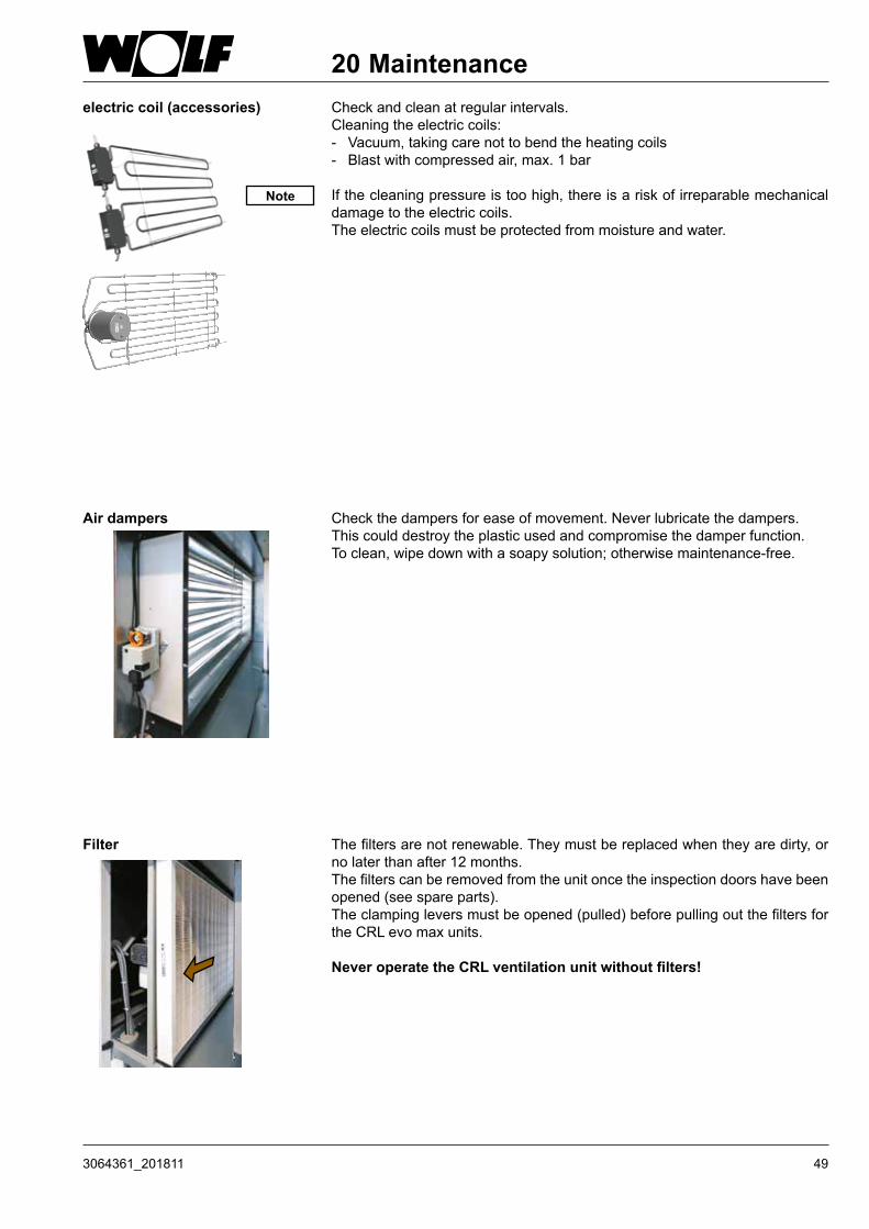
Air dampers Check the dampers for ease of movement. Never lubricate the dampers. This could destroy the plastic used and compromise the damper function.To clean, wipe down with a soapy solution; otherwise maintenance-free.
Filter The filters are not renewable. They must be replaced when they are dirty, or no later than after 12 months. The filters can be removed from the unit once the inspection doors have been opened (see spare parts).The clamping levers must be opened (pulled) before pulling out the filters for the CRL evo max units.
Never operate the CRL ventilation unit without filters!
electric coil (accessories) Check and clean at regular intervals.Cleaning the electric coils:- Vacuum, taking care not to bend the heating coils- Blast with compressed air, max. 1 bar
If the cleaning pressure is too high, there is a risk of irreparable mechanical damage to the electric coils.The electric coils must be protected from moisture and water.
Note

50 3064361_201811
Servomotors on the dampers The motors are maintenance-free.At regular intervals, check that the connection from the servomotor to the damper drive is firmly seated.
Condensate pan Regularly check the condensate pan for possible soiling and clean if required (see checklist).
Trap Regularly check the DN 50 trap (accessory) for possible soiling and clean if required (see checklist).Refill the trap with water before returning into use.
h
20 Maintenance

513064361_201811
21 Notes

WOLF GmbH / Postfach 1380 / D-84048 Mainburg Tel. +49.0.87 51 74- 0 / Fax +49.0.87 51 74- 16 00 / www.WOLF.eu