Embed Size (px)
Citation preview
1
Point no.
1
2
3
3.1
3.2
3.3
3.4
3.5
3.6
3.7
3.8
4
4.1
4.2
5
5.1
5.2
5.3
6
6.1
6.2
6.2.1
6.2.2
Description
Declaration of conformity
General
Safety
Safety symbol of in this operating
instructions
Qualification of personnel & training
Danger or non-observance of the
instructions
Safety consciousness
Safety instructions for the user/operator
Safety instructions for maintenance,
inspection and installation work
Unauthorized modification
and manufacturing of spare parts
Inadmissible modes of operation
Transport & interim storage
Transport
Interim storage
Description / related documents
Marking for CE requirements
Design standards / related documents
Sectional drawing & functional principle
Installation
General
Installation position
Gate valves
Globe valves
Page no.
2
3
3
3
4
4
4
4
4
4
5
5
5
5
5
5
5
5
7
7
8
8
8
Point no.
6.2.3
6.2.4
6.3
6.4
7
7.1
7.1.1
7.1.2
7.1.3
7.1.4
7.2
8
8.1
8.1.1
8.1.2
8.2
8.3
9
9.1
9.2
10
Annexure I
Description
Swing check valves
Piston check valves
Welding instructions / installation of
pipe
Actuated valves
Commissioning/
Decommissioning
Commissioning
General
Operation
Functional Check
Actuated valves
Decommissioning
Maintenance / Repair
Safety Instructions
Dismantling of valves
Removing Actuators
Maintenance
Valve Reassembly
Troubleshooting
General
Faults & Remedies
Valve weights
Do’s & Don’ts
Page no.
8
8
8
8
8
8
8
9
9
9
9
9
9
9
10
10
10
10
10
10
11
11 & 12
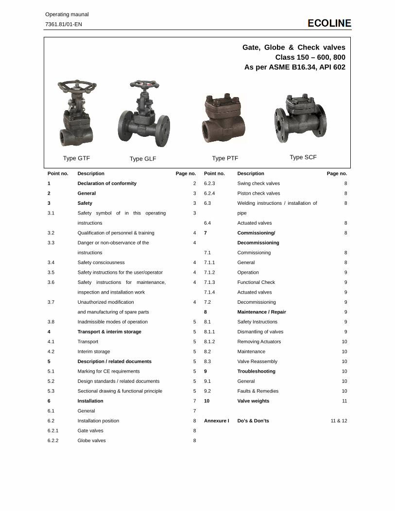
Gate, Globe & Check valves Class 150 – 600, 800
As per ASME B16.34, API 602
Type GTF Type GLF Type PTF Type SCF
Operating maunal
7361.81/01-EN
1 EC Declaration of Conformity
Herewith we, KSB Valves (Changzhou) Co., Ltd.
Registered Office:
No. 68 Huanbao Four Road,
Environment Protection Industrial Park,
Xinbei District, Changzhou City
Jiangsu Province
P.R. China
Declare that the valves listed below satisfy the safety requirements laid down in the Pressure Equipment Directive 97/23/EC
(PED).
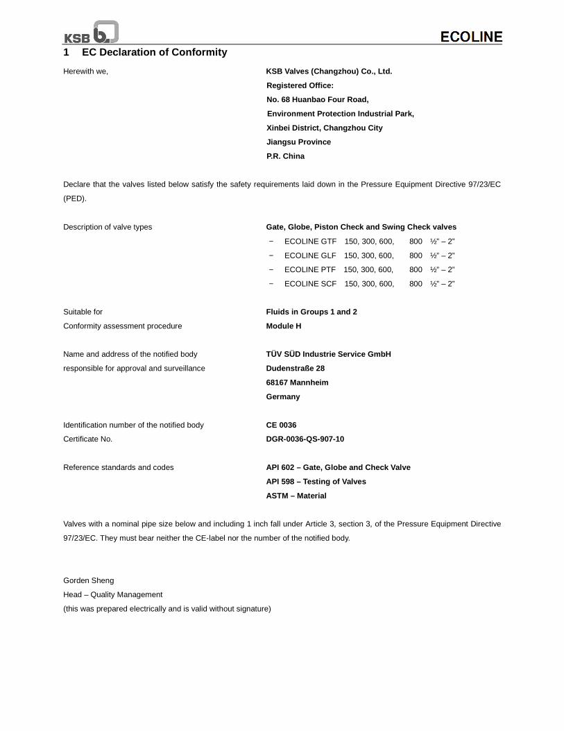
Description of valve types Gate, Globe, Piston Check and Swing Check valves
− ECOLINE GTF 150, 300, 600, 800 ½” – 2”
− ECOLINE GLF 150, 300, 600, 800 ½” – 2”
− ECOLINE PTF 150, 300, 600, 800 ½” – 2”
− ECOLINE SCF 150, 300, 600, 800 ½” – 2”
Suitable for Fluids in Groups 1 and 2
Conformity assessment procedure Module H
Name and address of the notified body TÜV SÜD Industrie Service GmbH
responsible for approval and surveillance Dudenstraße 28
68167 Mannheim
Germany
Identification number of the notified body CE 0036
Certificate No. DGR-0036-QS-907-10
Reference standards and codes API 602 – Gate, Globe and Check Valve
API 598 – Testing of Valves
ASTM – Material
Valves with a nominal pipe size below and including 1 inch fall under Article 3, section 3, of the Pressure Equipment Directive
97/23/EC. They must bear neither the CE-label nor the number of the notified body.
Gorden Sheng
Head – Quality Management
(this was prepared electrically and is valid without signature)

3
2 General
These operating instructions apply to KSB – forged steel
gate, globe and check valves.
Development and production of KSB valves are subject to a
QA system according to DIN/ISO 9001.
Correct installation and maintenance or repair will ensure
trouble free operation of the valves.
The manufacturer does not assume any liability for these
valves if the operating instructions are not being observed.
The valves are marked to ASME B16.34 if
required with an arrow indicating the flow
direction, Nominal size, Class, material of body,
manufacturer.
The valves must not be operated beyond the limits defined in
the operating instructions/contractual documentation/type
series booklet. Any use beyond the above conditions will
lead to overload which the valves cannot withstand.
Non-observance of this warning may lead to
personal injury or property damage, e.g.:
- Injury caused by escaping fluids (cold/hot, toxic or under
pressure.)
- Incorrect operation or destruction of the valve.
The descriptions and instructions in this manual refer to the
standard versions but also apply to the related variants.
These operating instructions do not consider:
- incidents which may occur during installation, operation and
maintenance.
- the local safety regulations. It is the user’s responsibility to
ensure that they are observed, also by the installation staff
involved.
For actuated valves, the specified connection parameters
and the installation and maintenance instructions, including
the operating manual for the actuator must be observed.
Handling a valve requires skilled and
experienced personnel.
The personnel in charge of operation, maintenance and
installation of this valve must be aware of the interaction
between the valve and the plant.
Operator’s errors concerning the valve may have serious
consequences for the entire plant, e.g.:
- fluid may escape
- downtime of the plant/machine
- adverse effect/reduction/increase of the efficiency/function
of a plant/machine.
For further questions or in case of damage to the valve,
please contact your KSB Sales Office.
The specifications (operating data) of the valves are listed in
the technical documentation & type series booklet of the
related valve (see also section 5).
When returning valves to the manufacturer, please refer to
section 4.
The manufacturer is not liable for any claims
resulting from a failure to implement or
implement properly the instructions contained in these
operating instructions or resulting from the actions of a third
party.
In particular, the manufacturer is not liable
for direct or indirect consequential damage
that has occurred for whatever reason.
3 Safety
This manual contains basic instructions to be complied with
during operation and maintenance. It is therefore vital for the
fitter and the operator/user to read this manual before
installing/commissioning the valve. Also, this manual must
always be available at the site where the valve is installed.
It is not enough to observe the general instructions listed in
the section “safety”, the specific safety instructions listed in
the other sections should also be observed.
3.1 Safety symbol of in this operating
instructions
Safety instructions put forth in this instruction manual whose
non-observance would involve the risk of personal injury are
specially marked with the general hazard symbol:
in accordance with DIN 4844 (safety sign W9), or with the
electric voltage warning sign:
In accordance with DIN 4844 (safety sign W 8),
Caution
Caution
Attention
Attention
Safety instructions whose non-observance would involve
hazard to the valve and jeopardize its operation have been
marked with the word
Instructions directly attached to the valve, (e.g. nominal
pressure) must be complied with and maintained in a legible
condition.
3.2 Qualification of personnel and training
The personnel for operation, maintenance,
Inspection and Installation must be adequately
qualified for the work involved. The personnel’s
responsibilities, competence and supervision must be clearly
defined by the user. If the personnel in question is not
already in possession of the requisite know-how, appropriate
training and instructions must be provided. If deemed
necessary, the manufacturer/supplier will provide such
training and instructions at the user’s request. In addition, the
user is responsible for ensuring that the contents of these
operating instructions are fully understood by the personnel
in question.
3.3 Danger or non-observance of the safety
Instructions
Non-observance of the safety instructions may lead
to personal injury and also to danger for the
environment and the valve itself. Non-observance of these
safety instructions will also forfeit the user’s warranty.
Such noncompliance could, for example, result in:
- failure of essential functions of the valve/plant
- failure of prescribed maintenance and repair practices
- hazard to people by electrical, mechanical or chemical
effects
- hazard to the environment due to leakage of hazardous
substances
3.4 Safety consciousness
The safety instructions contained in this manual, the
applicable national accident prevention regulations and any
of the user’s own applicable internal work, operation or
safety instructions must be fully complied with.
3.5 Safety instructions for the user/operator
Any hot or cold parts of the valve (e.g. body or hand
wheel) that could pose a hazard must be protected
by the user against accidental contact.
Leakage (e.g. at the stem seal) of hazardous substances
(e.g. explosive, toxic, hot) must be drained so as to avoid all
danger to people or the environment. All relevant laws must
be observed.
Electrical hazards must be effectively prevented.
(For details, please refer to the VDE standards
and/or the local energy supply utility regulations).
3.6 Safety instructions for maintenance,
inspection and installation work
The user is responsible for ensuring that all
maintenance, inspection and installation work is
carried out by authorized, adequately qualified staff who are
thoroughly familiar with this instruction manual.
All work on a valve may only be performed when the valve is
un-pressurized and has cooled down. This means that the
temperature of the medium in all the valve’s chambers must
be lower than the vaporization point of the medium.
All work on actuated valves may only be done after the
actuator has been disconnected from its energy supply. The
procedure described in the operating instructions to shut
down the actuator must be observed.
Valves in contact with hazardous media must be
decontaminated.
Immediately following completion of the work, all safety
relevant and protective devices must be reinstalled and/or
reenabled.
Prior to recommissioning, refer to the points listed under
section 7, Commissioning.
3.7 Unauthorised modification and
manufacturing of spare parts
The equipment shall not be altered or modified in
any way prior to consultation with the manufacturer.
Genuine spare parts and accessories authorized by the
manufacturer will ensure operational safety. The
manufacturer cannot be held responsible for damage
resulting from the use of non-genuine parts or accessories.
Caution
3.8 Inadmissible modes of operation
Operational safety and reliability of the valve supplied is only
warranted for its designated use as defined in section 2
“General” of the operating instructions. The limits stated in
the technical documentation must not be exceeded under
any circumstances.
4 Transport & interim storage
4.1 Transport
The valves in the as-supplied condition are ready for
operation.
For transport and storage, the valves must always be
maintained in the closed position and the connection ends
must be plugged using suitable means (e.g. covers, plastic
sheets, etc.) to prevent damage to the seats.
To prevent damage, do not suspend the valve
by its handwheel or the actuator.
For valve weights, please refer to Section 10.
After delivery or prior to installation, the valve should be
checked for damage during transit.
4.2 Interim storage
The valves must be stored in such a way that correct
operation is assured even after prolonged storage. This
comprises:
- Storing in the closed position (to protect the seats from
damage).
- Suitable measures against contamination, frost and
corrosion (e.g. by using plastic sheets or end covers).
5 Description / Related Documents
The sectional drawings shown as below are examples for the
general design of KSB valves. For drawings and other
information pertaining to a specific valve series, please refer
to the relevant type series booklet.
5.1 Marking - for CE requirements
The valves are marked to PED 97/23/EC
In particular the marking contains at least following
- Manufacturer
- Year of production
- Valves type model or order no.
- NPS (DN) / (Inch)
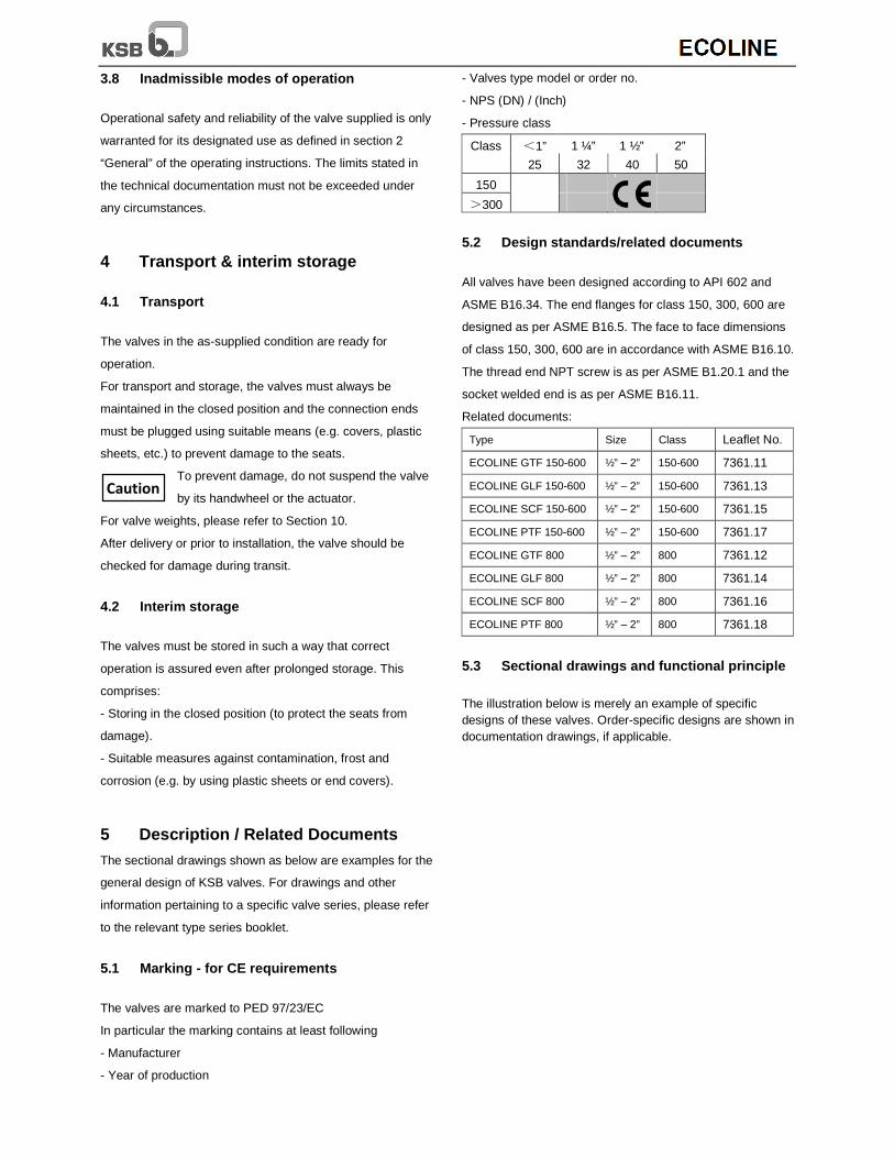
- Pressure class
Class <1” 1 ¼” 1 ½” 2”
25 32 40 50
150
>300
5.2 Design standards/related documents
All valves have been designed according to API 602 and
ASME B16.34. The end flanges for class 150, 300, 600 are
designed as per ASME B16.5. The face to face dimensions
of class 150, 300, 600 are in accordance with ASME B16.10.
The thread end NPT screw is as per ASME B1.20.1 and the
socket welded end is as per ASME B16.11.
Related documents:
Type Size Class Leaflet No.
ECOLINE GTF 150-600 ½” – 2” 150-600 7361.11
ECOLINE GLF 150-600 ½” – 2” 150-600 7361.13
ECOLINE SCF 150-600 ½” – 2” 150-600 7361.15
ECOLINE PTF 150-600 ½” – 2” 150-600 7361.17
ECOLINE GTF 800 ½” – 2” 800 7361.12
ECOLINE GLF 800 ½” – 2” 800 7361.14
ECOLINE SCF 800 ½” – 2” 800 7361.16
ECOLINE PTF 800 ½” – 2” 800 7361.18
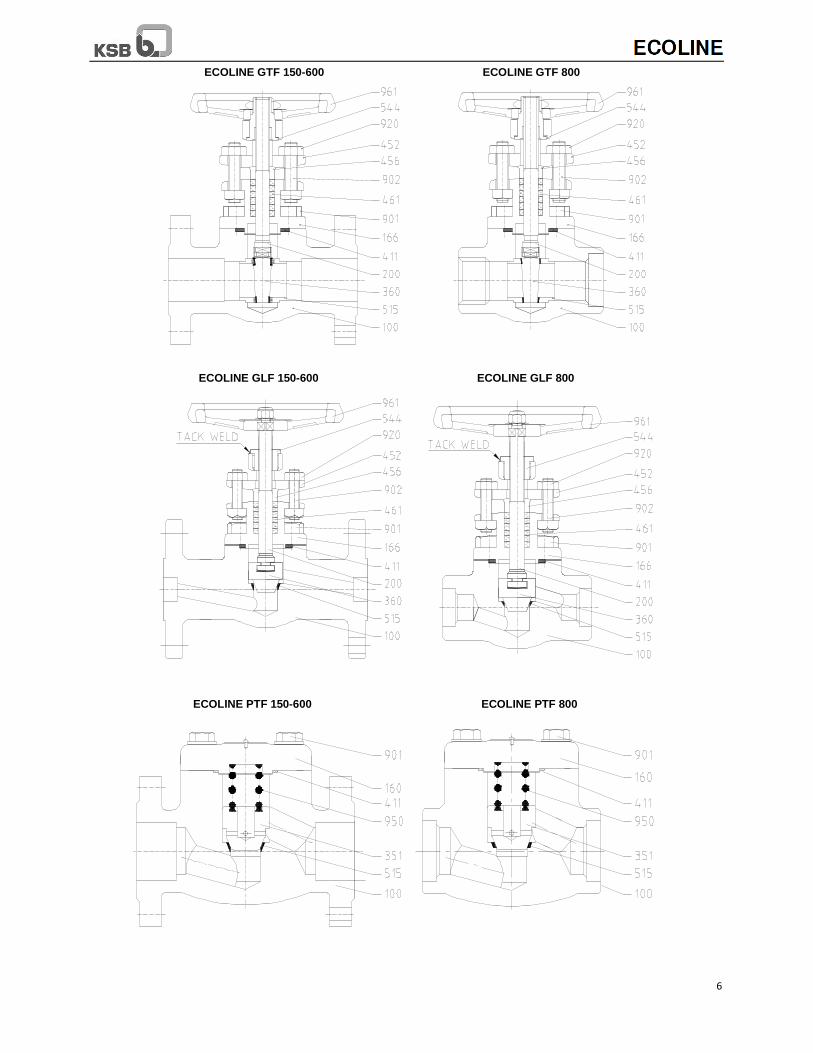
5.3 Sectional drawings and functional principle
The illustration below is merely an example of specific designs of these valves. Order-specific designs are shown in documentation drawings, if applicable.
Caution
6
ECOLINE GTF 150-600 ECOLINE GTF 800
ECOLINE GLF 150-600 ECOLINE GLF 800
ECOLINE PTF 150-600 ECOLINE PTF 800
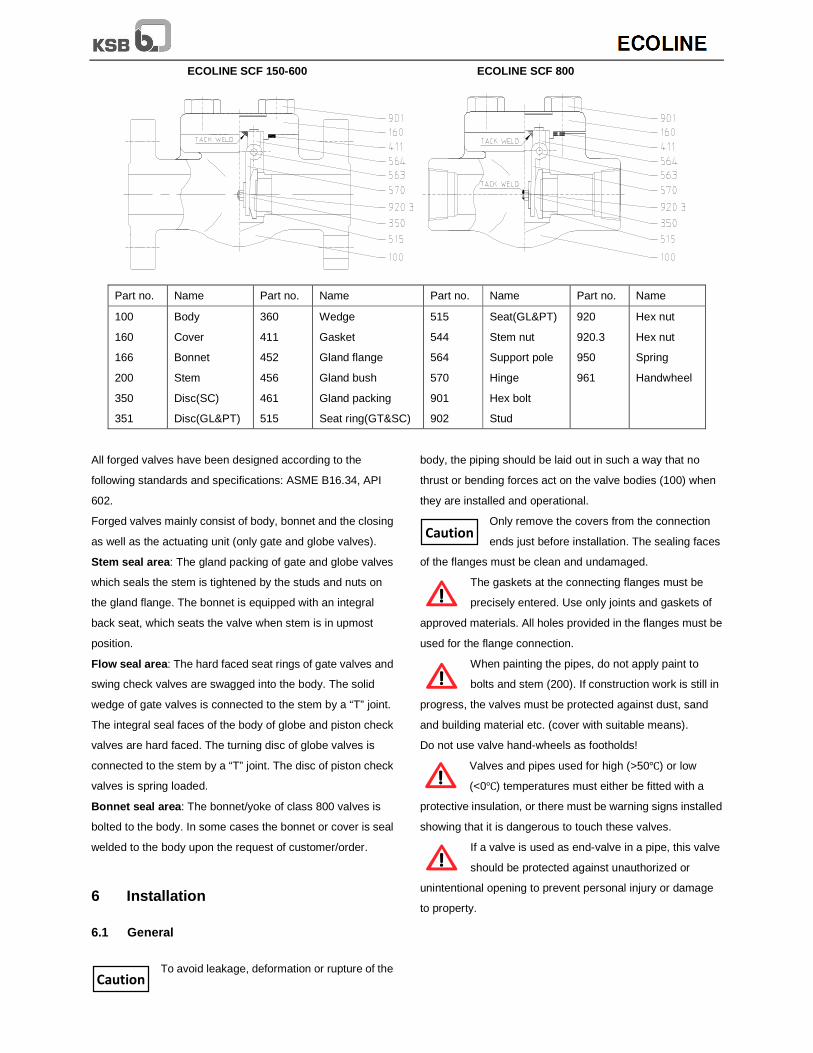
ECOLINE SCF 150-600 ECOLINE SCF 800
Part no. Name Part no. Name Part no. Name Part no. Name
100
160
166
200
350
351
Body
Cover
Bonnet
Stem
Disc(SC)
Disc(GL&PT)
360
411
452
456
461
515
Wedge
Gasket
Gland flange
Gland bush
Gland packing
Seat ring(GT&SC)
515
544
564
570
901
902
Seat(GL&PT)
Stem nut
Support pole
Hinge
Hex bolt
Stud
920
920.3
950
961
Hex nut
Hex nut
Spring
Handwheel
All forged valves have been designed according to the
following standards and specifications: ASME B16.34, API
602.
Forged valves mainly consist of body, bonnet and the closing
as well as the actuating unit (only gate and globe valves).
Stem seal area : The gland packing of gate and globe valves
which seals the stem is tightened by the studs and nuts on
the gland flange. The bonnet is equipped with an integral
back seat, which seats the valve when stem is in upmost
position.
Flow seal area : The hard faced seat rings of gate valves and
swing check valves are swagged into the body. The solid
wedge of gate valves is connected to the stem by a “T” joint.
The integral seal faces of the body of globe and piston check
valves are hard faced. The turning disc of globe valves is
connected to the stem by a “T” joint. The disc of piston check
valves is spring loaded.
Bonnet seal area : The bonnet/yoke of class 800 valves is
bolted to the body. In some cases the bonnet or cover is seal
welded to the body upon the request of customer/order.
6 Installation
6.1 General
To avoid leakage, deformation or rupture of the
body, the piping should be laid out in such a way that no
thrust or bending forces act on the valve bodies (100) when
they are installed and operational.
Only remove the covers from the connection
ends just before installation. The sealing faces
of the flanges must be clean and undamaged.
The gaskets at the connecting flanges must be
precisely entered. Use only joints and gaskets of
approved materials. All holes provided in the flanges must be
used for the flange connection.
When painting the pipes, do not apply paint to
bolts and stem (200). If construction work is still in
progress, the valves must be protected against dust, sand
and building material etc. (cover with suitable means).
Do not use valve hand-wheels as footholds!
Valves and pipes used for high (>50℃) or low
(<0℃) temperatures must either be fitted with a
protective insulation, or there must be warning signs installed
showing that it is dangerous to touch these valves.
If a valve is used as end-valve in a pipe, this valve
should be protected against unauthorized or
unintentional opening to prevent personal injury or damage
to property.
Caution
Caution
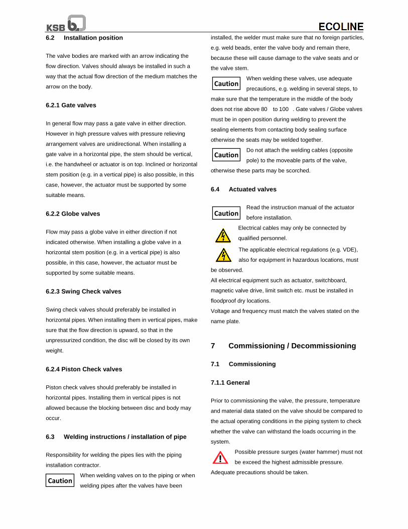
6.2 Installation position
The valve bodies are marked with an arrow indicating the
flow direction. Valves should always be installed in such a
way that the actual flow direction of the medium matches the
arrow on the body.
6.2.1 Gate valves
In general flow may pass a gate valve in either direction.
However in high pressure valves with pressure relieving
arrangement valves are unidirectional. When installing a
gate valve in a horizontal pipe, the stem should be vertical,
i.e. the handwheel or actuator is on top. Inclined or horizontal
stem position (e.g. in a vertical pipe) is also possible, in this
case, however, the actuator must be supported by some
suitable means.
6.2.2 Globe valves
Flow may pass a globe valve in either direction if not
indicated otherwise. When installing a globe valve in a
horizontal stem position (e.g. in a vertical pipe) is also
possible, in this case, however, the actuator must be
supported by some suitable means.
6.2.3 Swing Check valves
Swing check valves should preferably be installed in
horizontal pipes. When installing them in vertical pipes, make
sure that the flow direction is upward, so that in the
unpressurized condition, the disc will be closed by its own
weight.
6.2.4 Piston Check valves
Piston check valves should preferably be installed in
horizontal pipes. Installing them in vertical pipes is not
allowed because the blocking between disc and body may
occur.
6.3 Welding instructions / installation of pipe
Responsibility for welding the pipes lies with the piping
installation contractor.
When welding valves on to the piping or when
welding pipes after the valves have been
installed, the welder must make sure that no foreign particles,
e.g. weld beads, enter the valve body and remain there,
because these will cause damage to the valve seats and or
the valve stem.
When welding these valves, use adequate
precautions, e.g. welding in several steps, to
make sure that the temperature in the middle of the body
does not rise above 80� to 100�. Gate valves / Globe valves
must be in open position during welding to prevent the
sealing elements from contacting body sealing surface
otherwise the seats may be welded together.
Do not attach the welding cables (opposite
pole) to the moveable parts of the valve,
otherwise these parts may be scorched.
6.4 Actuated valves
Read the instruction manual of the actuator
before installation.
Electrical cables may only be connected by
qualified personnel.
The applicable electrical regulations (e.g. VDE),
also for equipment in hazardous locations, must
be observed.
All electrical equipment such as actuator, switchboard,
magnetic valve drive, limit switch etc. must be installed in
floodproof dry locations.
Voltage and frequency must match the valves stated on the
name plate.
7 Commissioning / Decommissioning
7.1 Commissioning
7.1.1 General
Prior to commissioning the valve, the pressure, temperature
and material data stated on the valve should be compared to
the actual operating conditions in the piping system to check
whether the valve can withstand the loads occurring in the
system.
Possible pressure surges (water hammer) must not
be exceed the highest admissible pressure.
Adequate precautions should be taken.
Caution
Caution
Caution
Caution
In new pipe systems and especially after repair work, the
system should be flushed with the valves fully open to
remove solids, e.g. weld beads, which may damage the
seats.
7.1.2 Operation
The valves are closed by turning the handwheel in the
clockwise direction (top view) and opened in the counter
clockwise direction.
Using additional levers when turning the
handwheel is not admissible, because excess
force may damage the valve.
7.1.3 Functional Check
The following functions should be checked:
Before commissioning, the shut-off-function of the valves
should be checked by repeated opening and closing.
The gland packing (461) should be checked when it is
subjected to the full operating pressure and temperature for
the first time. If necessary, retighten the nuts (920) at the
gland flange (452) evenly.
The cover flange connection (901) and the gasket (411)
should be checked for tightness after the first temperature
rise at the valves. In case of leakage at the gasket (411), the
connection should be tightened crosswise, evenly and in a
clockwise direction.
Open the gate and globe valve by one or two
turns of the handwheel prior to retightening the
nuts 920 to prevent jamming of the seat.
Retightening of the nuts (901) of the cover bolting especially
applies to valves used in heat transfer systems to DIN 4754.
7.1.4 Actuated valves
On valves with electric/pneumatic/hydraulic actuator, the
strokes/forces must be limited.
Electric actuators should be wired as follows:
Always use suitable spare parts and tools, even in
emergencies, because otherwise correct operation of the
valves cannot be assured.
Switches are factory set. Do not tamper with
settings. To readjust settings refer instruction
manual of actuator manufacturer and / or contact your
nearest KSB office.
For setting of actuator, please refer instruction manual which
will be kept in the wiring side compartment/cover of actuator.
7.2 Decommissioning
During extended shutdowns periods, liquids liable to change
their condition due to polymerization, crystallization,
solidification etc. must be drained from the piping system. If
necessary, the piping system should be flushed with the
valves fully open.
8 Maintenance/Repair
8.1 Safety Instructions
Maintenance and repair work may only be carried out by
skilled and qualified personnel.
For all maintenance and repair work, the safety instructions
listed below and also the general notes in section 3 must be
observed.
Always use suitable spare parts and tools, even in
emergencies, because otherwise correct operation of the
valves can not be assured.
8.1.1 Dismantling of valves
Before removing the complete valve from the pipe, or before
repair or maintenance work on the valve itself, i.e.
- before removing cover or bonnet from the body
- before removing the gland flange and gland bush to replace
packing rings
- before removing an actuator bolted directly to the yoke
head
The entire valve must be unpressurized and must
have cooled down sufficiently so that the
temperature of the medium in all the valve’s chambers is
lower than the vaporization point of the medium, to prevent
scalding.
Opening pressurized valves will cause danger to
life and limb!
If toxic or highly inflammable substances or liquids whose
residues may cause corrosion by interaction with the air
humidity were handled by the valve, then the valve should be
drained and flushed or vented.
If necessary, wear safety clothing and a face guard/mask.
Caution
Caution
Caution
Depending on the installation position, any liquid remaining
in the valve may have to be removed.
Prior to possible transport, the valves must be flushed and
drained carefully.
If you have any questions, please contact your KSB Sales
Office.
8.1.2 Removing Actuators
If actuators powered by an external source of
energy (electric, pneumatic, hydraulic) need to be
removed from the valves or dismantled, the energy supply
must be shut down prior to starting any repair work and the
instructions in the sections 3, 8.1.1 and the operating
instructions of the actuator must be observed.
Valve actuators with integrated spring-loading
feature cannot be removed.
Springs under tension!
If you have any questions, please contact your KSB Sales
Office.
8.2 Maintenance
Our valves are largely maintenance free, materials of sliding
parts were selected to keep wear to a minimum. To ensure
reliable operation and to reduce repair costs, all valves -
especially those which are seldom operated or where access
is difficult -should be checked periodically.
The user is responsible for defining appropriate intervals for
checks and maintenance, depending on the application of
the valve.
The service life of non-maintenance-free valves can be
extended by:
- lubricating movable parts such as stem (200) and gland
bolts (not for oxygen valves) and provided in the case of gate
valve using suitable lubricants to DIN 51825 / equivalent
- timely changing of the packing rings
- timely replacing of the cover gasket (411)
The safety instructions in sections 3, 8.1 and the notes in
section 9 must be observed.
8.3 Valve Reassembly
Valve reassembly shall be effected in reverse order to
dismantling.
To maintain functional reliability, new gaskets and gland
packing shall be used whenever the valve is reassembled.
After reassembly and prior to commissioning / start-up, the
valves shall be subjected to a leak test in accordance with
DIN 3230, Part 3l, or API 598 and ASME B16.34 Section 8.
9 Troubleshooting
9.1 General
All repair and service work must be carried out by qualified
personnel using suitable tools and genuine spare parts.
The safety instructions in sections 3 and 8 must be observed.
9.2 Faults & Remedies
Fault - Leakage at the seat
Remedy - Remachine the seat on wedge/disc
and body using suitable regrinding equipment
after dismantling the valve. Regrinding
of body and cone seats should be continued until the seats
show a smooth and even ring.
Fault - Leakage at the cover/bonnet gasket
Remedy - Retighten the cover/bonnet flange connection
Remedy - Replace the gasket (411) after removing the
cover/bonnet bolts (901). Clean the surfaces carefully before
inserting a new gasket.
On asbestos-free gaskets, no additional
sealing agents may be used. When using anti
adhesive coatings, use sealing agents explicitly
recommended by the manufacturer of the sealing material.
If you have any further questions please contact nearest
KSB Sales office.
Fault - Leakage of the Stuffing Box
Remedy - Retighten the stuffing box with the nuts (920) at
the gland flange (452). Make sure that the friction forces at
the stem do not increase too much.
Remedy - Replace the packing rings of the stuffing box;
Unscrew the nuts (920) and lift the gland flange (452). Clean
the stuffing box chamber thoroughly before inserting new
packing rings. Split packing rings should be inserted in such
a way that the slots are offset by 120° to 180°.
Do not replace packing while the valve is
pressurized. The back seat bushing is not intended
to maintain a seal during replacement.
Caution Caution
Caution
11
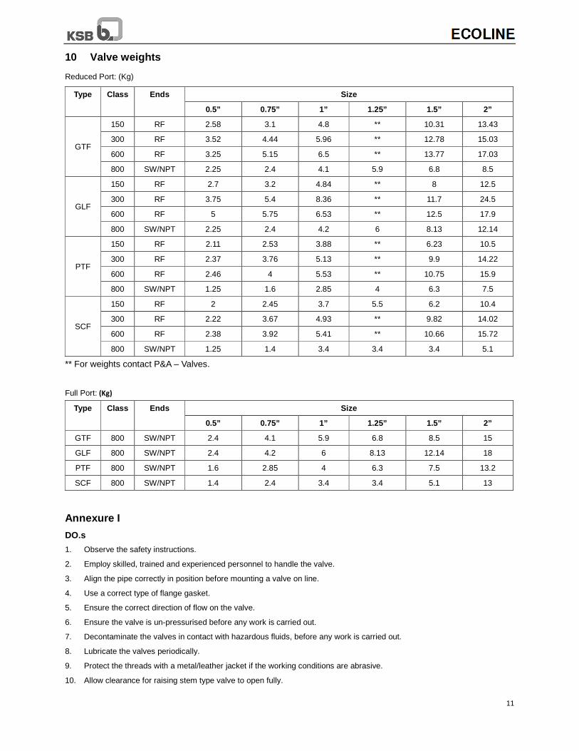
10 Valve weights
Reduced Port: (Kg)
Type Class Ends Size
0.5” 0.75” 1” 1.25” 1.5” 2”
GTF
150 RF 2.58 3.1 4.8 ** 10.31 13.43
300 RF 3.52 4.44 5.96 ** 12.78 15.03
600 RF 3.25 5.15 6.5 ** 13.77 17.03
800 SW/NPT 2.25 2.4 4.1 5.9 6.8 8.5
GLF
150 RF 2.7 3.2 4.84 ** 8 12.5
300 RF 3.75 5.4 8.36 ** 11.7 24.5
600 RF 5 5.75 6.53 ** 12.5 17.9
800 SW/NPT 2.25 2.4 4.2 6 8.13 12.14
PTF
150 RF 2.11 2.53 3.88 ** 6.23 10.5
300 RF 2.37 3.76 5.13 ** 9.9 14.22
600 RF 2.46 4 5.53 ** 10.75 15.9
800 SW/NPT 1.25 1.6 2.85 4 6.3 7.5
SCF
150 RF 2 2.45 3.7 5.5 6.2 10.4
300 RF 2.22 3.67 4.93 ** 9.82 14.02
600 RF 2.38 3.92 5.41 ** 10.66 15.72
800 SW/NPT 1.25 1.4 3.4 3.4 3.4 5.1
** For weights contact P&A – Valves.
Full Port: (Kg)
Type Class Ends Size
0.5” 0.75” 1” 1.25” 1.5” 2”
GTF 800 SW/NPT 2.4 4.1 5.9 6.8 8.5 15
GLF 800 SW/NPT 2.4 4.2 6 8.13 12.14 18
PTF 800 SW/NPT 1.6 2.85 4 6.3 7.5 13.2
SCF 800 SW/NPT 1.4 2.4 3.4 3.4 5.1 13
Annexure I
DO.s
1. Observe the safety instructions.
2. Employ skilled, trained and experienced personnel to handle the valve.
3. Align the pipe correctly in position before mounting a valve on line.
4. Use a correct type of flange gasket.
5. Ensure the correct direction of flow on the valve.
6. Ensure the valve is un-pressurised before any work is carried out.
7. Decontaminate the valves in contact with hazardous fluids, before any work is carried out.
8. Lubricate the valves periodically.
9. Protect the threads with a metal/leather jacket if the working conditions are abrasive.
10. Allow clearance for raising stem type valve to open fully.
11. Flush the valves in fully open condition to remove foreign material like welding flux, spatter, slag, dust etc. to avoid
damage of seats.
12. Check shut-off function by repeatedly opening and closing before commissioning.
13. Check the frequency and voltage of actuators to match with the line voltage and frequency.
14. If gasket leak is observed, tighten gasket bolts crosswise evenly in a clock wise direction.
15. After attaining the full operating pressure and temperature, check and if necessary, tighten the gland nut / Body –bonnet
nuts.
16. When a gate valve is fully opened, screw it down 1/4 turn to prevent sticking.
17. During storage position the valve such that the stem is upright.
18. For globe valve follow the instructions carefully for direction of installation.
DON’Ts
1. Don’t expose the valves to dust, sand, building material etc. during storage.
2. Don’t use unauthorised spares.
3. Don’t remove end protective covers before installation.
4. Don’t use valve hand-wheels as foot holds.
5. Don’t exceed the limits stated in technical documentation.
6. Don’t store the valve in open condition.
7. Don’t attempt to dismantle the pressurised valve.
8. Don’t use a valve to pull an unsupported and badly aligned pipes into position.
9. Don’t leave a gate valve in crack open condition.
10. Don’t use a gate valve for throttling.
11. Don’t force a gate valve closed with a wrench.
12. Don’t use a flat disc globe valve for start-up / vent application.
13. Once the valve is installed and commissioned do not tamper the torque & limit switches in case of valve with electrical
actuator.
KSB Valves (Changzhou) Co., Ltd.
No. 68 Huanbao Four Road, Environment Protection Industrial Park, Xinbei District, Changzhou (China)
Tel: +86 21 6430 8030 Fax: +86 519 8168 5855 www.ksb.com