Embed Size (px)
Citation preview
Gas Insulated Substation Definitions and Basics Course No: E05-011
Credit: 5 PDH
Velimir Lackovic, Char. Eng.
Continuing Education and Development, Inc. 9 Greyridge Farm Court Stony Point, NY 10980 P: (877) 322-5800 F: (877) 322-4774 [email protected]
GAS INSULATED SUBSTATION DEFINITIONS AND BASICS
DEFINITIONS
This course is based on terms used in IEEE and IEC regulations. Several crucial terms
are for better understanding of the presented material.
GIS - There are two terms presented in IEC “Gas Insulated Switchgear” and IEEE
“Gas Insulated Substations.”
In IEEE C37.122 - Gas insulated switchgear (GIS): a compact, multicomponent
device, enclosed in a grounded metallic case in which the basic insulating medium is
SF6 gas and which typically includes buses, switches, circuit breakers, and other
related devices.
In IEC 62271-203 - Metal-enclosed switchgear and control gear: switchgear and
control gear devices with an external metal case were planned to be grounded, and
complete except for external connections. There is no precise definition of GIS.
Metal-Enclosed Switchgear and Control gear - Switchgear and control gear devices
with an external metal case were planned to be grounded and complete except for
external connections, as described in IEC 62271-203.
Gas Insulated Metal-Enclosed Switchgear - Metal- enwrapped switchgear in which the
insulation is received, at least partially, by an insulating gas other than air at
atmospheric pressure, as described in IEC 62271-203. This definition typically relates
to high voltage switchgear and control gear. Three-phase enwrapped gas isolated
switchgear applies to switchgear with the three phases enwrapped in a common case.
Single-phase enwrapped gas insulated switchgear relates to switchgear with each
phase closed in a single independent case.
Gas Insulated Switchgear Enclosure - Part of the gas-isolated metal- enwrapped
switchgear holding the isolating gas under the dictated conditions essential to keep
the greatest isolation level safely, guarding the device against external impacts and
giving a high degree of protection to staff, as described in IEC 62271-203. In IEEE
C37-122, earthed element of the gas isolated metal-enclosed switchgear device
holding the isolating gas under the dictated conditions essential to keep the needed
isolation level, guarding the device against external impacts and giving a high degree
of protection from an approach to live energized parts.
GIS Compartment - A part of a gas isolated switchgear assembly that is closed except
for gaps needed for interconnection gives isolating gas separation from other
compartments. A space may be assigned by the main elements in it, for example,
circuit breaker space, disconnect switch space, bus space, and so on, as described in
IEEE C37.122. A space of GIS as described in IEC 62271-203 as part of a gas isolated
metal-cased switchgear, is completely closed except for gaps needed for
interconnection and control. A space may be assigned by the main element held
therein, for example, circuit breaker space or bus bar space.
Design Pressure of Enclosures - The greatest gas pressure to which a gas isolated
switchgear case will be subjected under normal service operation, including the
heating impacts of rated continuous current, as described in IEEE C37.122.
Gas Monitoring Systems - Any devices for measuring, signalizing, or providing remote
warning of the condition or change in condition of the gas in the case, such as
pressure, density, moisture level, and so on, as described in IEEE C37.122.
Gas Leakage Rate (Absolute) - The quantity of gas getting away by a time unit showed
in units of Pa m3/s, as described in IEEE C37.122.
Gas Leakage Rate (Relative) - The absolute leakage rate associated to the total
quantity (mass or volume) of gas in each space at the rated filling pressure (or density).
It is defined in percentage per year, as described in IEEE C37.122.
Gas Pass Through Insulator - An internal insulator backing one or more conductors
specifically made to provide the passage of gas between adjoining spaces, as
described in IEEE C37.122.
Gas Zone - A part of the GIS that may be comprised of one or several gas spaces that

have a common gas monitoring system. The case can be single-phase or three-phase,
as described in IEEE C37.122.
Local Control Cubicle (or Cabinet) (LCC) - A cubicle or cabinet usually holding
secondary devices including control and interlocking, measuring, indicating, alarm,
annunciation, and mimic one-line diagrams related with the primary devices. It may
also let in protective relays if defined by the user.
Support Insulator - An internal isolator backing one or more conductors, as described
in IEC 62271-203.
Partition - Part of an assembly distinguishing one space from other spaces. It gives
gas isolation and backing for the conductor (gas barrier isolator), as described in
C37.122. A space as described in IEC 62271-203, which is a backing isolator of gas
isolated metal enclosed switchgear distinguishing one space from other spaces.
Design Pressure of Cases - Relative pressure utilized to find out the design of the
case. It is at least same to the maximum pressure in the case at the greatest
temperature that the gas used for insulation can reach under defined maximum service
circumstances. The transient pressure happening during and after a breaking
procedure (e.g., a circuit breaker) is not to be studied in the decision of the design
pressure, as described in IEC 62271-203.
Relative Pressure across the Partition - Relative pressure across the partition is at
least same to the greatest relative pressure across the space during maintenance
actions. The transient pressure happening during and after a breaking procedure (e.g.,
a circuit breaker) is not to be studied in the decision of the design pressure, as
described in IEC 62271-203.
Operating Pressure of Pressure Relief Element - Relative pressure selected for the
opening procedure of pressure relief elements, as described in IEC 62271-203.
Routine Test Pressure of Cases and Partitions - Relative pressure to which all cases
and partitions are submitted after production, as described in IEC 62271-203.

Type Test Pressure of Cases and Partitions - Relative pressure to which all cases and
partitions are submitted for type test, as described in IEC 62271-203.
Rated Filling Pressure pre - Isolation and/or switching pressure (in Pa), to which the
equipment is filled before putting into operation. It is cited to at the standard
atmospheric air considerations of +20 °C and 101.3 kPa (or density) and may be
showed in relative or absolute conditions, as described in C37.122.
Bushing - An element that enables one or few conductors to go through a space, such
as a wall or a tank, and isolate the conductors from it, as described in IEC 62271-203.
Main Circuit - All the conductive elements of gas isolated metal-enwrapped switchgear
included in a circuit that is planned to transfer electrical energy, as described in IEC
62271-203.
Auxiliary Circuit - All the conductive elements of gas isolated metal-cased switchgear
included in a circuit (other than the major circuit) planned to control, measure, signal,
and modulate. The auxiliary circuits of gas isolated metal-cased switchgear include
the control and auxiliary circuits of the switching elements, as described in IEC 62271-
203.
Design Temperature of Cases – The greatest temperature that the cases can reach
under defined maximum service circumstances, as described in IEC 62271-203.
Service Period - The time until a servicing, including opening of the gas spaces, is
needed, as described in IEC 62271-203.
Transport Unit - Element of gas isolated metal-cased switchgear intended for shipping
without being taken apart, as described in IEC 62271-203.
MIXED SWITCHGEAR TECHNOLOGIES
Mixed switchgear technologies relates to the following combinations:
- AIS in compact and/or mixed arrangement

- GIS in mixed arrangement
- Hybrid IS in compact and/or mixed arrangement
RATINGS
The objective of ratings is to precisely use GIS devices based on an electric system
arrangement and features while decreasing the number of technical issues. These
ratings give interchangeable answers that are discerned across the industry and
decrease cost. The primary ratings are voltage, frequency, short time and peak
withstand current, isolation level, current, duration of short circuit and auxiliary
voltages and frequencies. In high voltage switchgear assembly, the ratings are
described for elements such as circuit breakers and disconnect switches, and
connecting conductors/bus, grounding (earthing) switches. Typically, they are
addressed in IEEE C37.100.1 or in IEC 62271-1 standards for switchgear devices. For
elements of high voltage switchgear like GIS, the ratings in the standards are followed
to make criteria and applications in the field. The arrangement of GIS has to consider
that the design and production costs of the metallic cases as pressure vessels of the
GIS apparatus are huge. Due to this, some GIS arrangements are grouped to address
several voltage ratings. One equipment technical standard addressing rated voltages
of 110 kV, 123 kV, 138 kV, and 145 kV, is described by the same class of GIS with
the same case.
Within this variety of voltage assortment, only several gas densities of SF6 gas
distinguish between the different voltage levels. In terms of current ratings, the
deviation between 2000 A, 2500 A, and 3000 A might only be a different number of
contact fingers or different wall thicknesses of conductors.
RATED MAXIMUM VOLTAGE
The high voltage (HV) points in regulations start at ratings above 52 kV in both IEC
and IEEE regulations. Below this voltage, the devices are treated as medium voltage
(MV). The common GIS high voltage ratings can be classified into four design parts or
device types for any producers, even if the split may differ somewhat. The lower high
voltage ratings are in 52 kV to 72.5 kV range. The second level range includes 100

kV, 123 kV, 145 kV and in some cases 170 kV rating. The next level range covers 245
kV and 300 kV with one GIS type. The fourth level range lets in the
362 kV and 420 kV voltages with the same GIS type. The 345 kV voltage level is
treated as 362 kV and is no longer advocated by standards. The third and fourth
ranges are used mainly in in North America and Europe, usually 245 kV and 420 kV
in Europe and 300 kV and 362 kV in North America. The reason behind this is the
accessibility of technical solutions like isolators at the moment when the voltage levels
were introduced. A summary of the voltage levels is shown in Table 1.
Table 1. IEEE and IEC rated voltage levels Rated max
voltage Um
Rated power frequency withstand voltage
Rated switching impulse
withstand voltage
Rated lightning impulse withstand
voltage (BIL)
IEC IEEE kV RMS kV RMS kV peak kV peak X X 72.5 140 - 325 X X 100 185 - 450 X X 123 230 - 550 X X 145 275 - 650 X X 170 325 - 730 X 245 425 - 900 X X 245 460 - 1050 X X 300 460 850 1050 X 362 500 850 1050 X X 362 520 950 1175 X X 420 650 1050 1425 X X 550 710 1175 1550 X X 550 740 1175 1550 X X 800 960 1425 2100
There are only two rated voltage levels left in the IEEE and IEC regulations, which
have two different possibilities for power frequency switching and lightning impulse
figures, which are 245 kV and 362 kV. The 550 kV rated voltage gives two isolation
levels for the rated power frequency withstand voltage.
RATED ISOLATION LEVEL
The ratings for isolation levels are gained from the power network to which the GIS
element is linked. Network circumstances, like lightning hits into overhead
transmission lines, their local probability, and their anticipated impact, are indicators

for the over-voltages that may happen. In the cable network arrangements, the cable
lengths and their associated over-voltages during switching procedures will impact this
rating. Rated isolation levels are fundamental parameters for the GIS design and have
a direct influence on the case diameter and, with this, a high cost influence in design
and manufacturing costs. Each voltage level in IEC and IEEE regulations has the
possibility of two or even more isolation levels. In GIS, the selection is typically made
in favour of the greatest requirement for the GIS.
As presented in Table 1, in majority of the cases the shown rated power frequency
withstand voltage, the rated switching impulse withstand voltage, and the rated
lightning impulse withstand voltage for the related rated maximum voltage level is the
greatest figure from IEC and IEEE regulations. Only the rated maximum voltage
categorizations of 245 kV and 362 kV have the possibility of two voltage levels.
RATED POWER FREQUENCY
Typically used power frequencies for GIS are 50 Hz developed in Europe and 60 Hz
developed in North America. Besides 16 1/3 Hz and 25 Hz for railroad technology use,
most of GIS usages are with 50 Hz and 60 Hz. These two frequencies are
disseminated world-wide and make regions and countries with one of the frequencies.
Few countries like Saudi Arabia and Japan use both frequencies.
The dielectric impact to the GIS arrangement of these frequencies is insignificantly
low. The thermal influence has to be conceived when the current rating is reaching the
limits, since at 60 Hz the power density is greater and, with this, the thermal rise.
Temperature boundaries should not be violated because of potential damage to
insulators or contact elements.
RATED CONTINUOUS CURRENT
The continuous current rating is a fundamental design measure of GIS for contactors
and contact sizing. The complex GIS arrangement allows close impact of the various
elements such as circuit breakers, disconnect and ground switches, current and
voltage transformers, and bus bars in terms of heat dissipation and temperature
increase. Due to this, the IEEE and IEC regulations ask for temperature rise tests to

support the adequate function of all elements that are part of GIS. A so-called standard
bay arrangement will be utilized for this test. One of the factors defined to a GIS
installation may indicate that the rated continuous current may be dissimilar for the
busbar or the feeders depending on the substations’ arrangement. Common rated
continuous currents are presented in Table 2.
Table 2. GIS common current ratings related to voltage classes Current (A)/Voltage (kV) 52-72.5 100-170 245-300 362-550 800 1100 5000-8000 X X X 4000-5000 X X X 3150-4000 X X X 2500-3150 X X X 1250-2500 X X
SHORT TIME RATED WITHSTAND CURRENT
The rated short time withstand current (IK), the peak withstand current (Ip), and the
short circuit duration (tK) (presented in the Tables 3 and 4) are fundamental sizing
arguments for GIS system. These figures have a high influence on the
electromechanical forces to the isolators and conductors, and on the thermal rise,
typically of the contact system. These figures are also evaluated by specific type
measurements to affirm the satisfactory function of the several GIS elements, such as
the bus bars, circuit breaker, disconnect and ground switch.
Table 3. Common GIS short-current ratings of related to voltage classes Current (kA)/Voltage (kV) 52-72.5 100-170 245-300 362-550 800 1100 63-100 X X X 50-63 X X X X 31.5-50 X X X 25-31.5 X X 16-25 X
RATED PEAK WITHSTAND CURRENT
The rated peak withstand current (Ip) is described by the DC time constant of the
electrical network. The rated peak withstand current is described as a factor of the
rated short time withstand current. Common figures in the network are 45ms for the
majority of the voltage classes, and up to 120ms in ultra-high voltage (UHV) electrical

networks. The associated factors are presented in Table 4. GIS devices are made to
accomplish these demands.
Table 4. Common factors to compute rated peak withstand currents (IP) Network Factor to calcualte IP DC constant (ms) 50 Hz up to 500 kV 2.5 45 60 Hz up to 500 kV 2.6 45 50/60 Hz 800 kV and above 2.7 60, 75,120
DURATION OF SHORT CIRCUIT
The rated duration of a short circuit (tK) depends on the electrical network protection
and is symmetrical. Over the years of network growth and upgrades, and with growing
short circuit ratings, this figure has evolved to shorter times. A common figure today is
1s, but also 0.5s is applicable. In some applications, 2s or 3s may be needed. The
duration of a short circuit has a major influence on the GIS design, and it is advised to
keep this short (refer to Table 5).
Table 5. Rated short circuit duration (tK) Rated short circuit duration, tK (s) Short 0.5 Standard 1 Long 2 Very long 3
RATED SUPPLY VOLTAGES
There are several different supply voltages that are used and they are addressed by
the regulations. This high variation is expensive for substation design and should be
cut down. Hence, the regulations provide some favoured figures. For existing
substations, this may not be feasible but new substation arrangement should follow
these advices (refer to Table 6).
Table 6. Rated supply voltages Rated supply voltages DC 48 V, 110 V and 125 V AC 208/120 V three-phase, 400/230 V
three phase and 230/115 V single phase

GAS INSULATED SWITCHGEAR PROCESSES - SULFUR HEXAFLUORIDE
It is vital for an engineer to understand the basics physics of the system and devices
being dealt with. Sulfur hexafluoride (SF6) is used as isolating medium in GIS
equipment. The first ionization potential of SF6 gas is similar to nitrogen (N2) while the
size of the SF6 molecule is much greater than a nitrogen molecule. This practically
means that the free path for an electron collision in SF6 gas is around a third of the
path that it is in N2. Kinetic energy is a function of velocity squared, and anticipating
linear acceleration, the mean electron to molecule collision in SF6 would have 16% of
the mean energy of a collision in N2.
As gas density is raised, the average free path is reduced and the electric field strength
needed to speed up electrons to the required velocity to induce ionization also rises.
SF6 gas has also another feature that makes it higher-ranking insulating gas. It is
electronegative. This practically means that SF6 molecules will pull in electrons to
make negative ions. This inhibits the extension of a discharge.
GIS CIRCUIT BREAKERS
The GIS equipment contains switchgear, switches and circuit breakers, linked with bus
bars and bushings. The circuit breaker is the main element of any GIS. Breaking
process in GIS circuit breakers is frequent topic in technical literature. It is sufficient to
mention that the features that make SF6 a highly effective isolating gas, along with the
relationship between its thermal and electrical conductivity features as it modifies from
plasma to an isolating gas, lead to SF6 being great breaking medium.
As the majority of interrupter arrangements are common to live tank, dead tank, and
GIS circuit breakers, it is allowed to talk about the circuit breaker as used in a GIS.
The interrupter in a dead tank and the GIS use see very similar circumstances. The
volume of the enclosing, being nearly the same, does not impact pressures and gas
flows that impact the interrupter’s operation. This is not the situation for a live tank
circuit breaker as the smaller gas quantity does impact interrupter operation. This
practically entails that an interrupter tested in a live tank breaker has to be retested in
a dead tank/GIS enclosure to check its operation.
The transient recovery voltages (voltages that are noticed and measured across the
circuit breaker contacts as it breaks) notice the same recovery voltages in either a
dead tank/live tank or GIS use. Transient recovery voltage needs to be looked at in
any usage.
GIS AVAILABILITY AND RELIABILITY
Availability and reliability are two crucial figures for the dispatcher of the electric power
system for commercial, private, or business. The equipment in the electrical power
system indicates high numbers in availability due to the high character of the products.
The needs of reliable power transfer are integral element of the electricity cost, and
the price of damages induced by power supply pauses are becoming more and more
into the focus of penalty payments to pay off for financial losses. Apart from the quality
of the elements, the influence of ambient circumstances like humidity, temperature,
dust, salty air, ice, and many others are the most determining arguments of reliability
values. In the situation of gas isolated devices like GIS, the influence of ambient
considerations does not affect the high voltage part immediately, which enhances the
GIS reliability figures. For a 110 kV GIS equipment the mean time between failures is
more than 10,000 years based on existing GIS equipment that is already in operation.
Typically, the compact size of the GIS allows indoor applications. In this situation, the
GIS non-high voltage elements are under constant ambient indoor conditions.
GIS DESIGN
SF6 established as the favoured breaking medium for high voltage circuit breakers so
it was natural to broaden the usage of SF6 to produce compact disconnect switches,
surge arresters, ground switches, interconnecting bus, voltage and current
transformers, and various terminations for connections to air insulated cables and
overhead lines, and direct power transformer links.
SF6 GAS
The SF6 gas pressures and properties utilized in circuit breakers have shown as
adequate for GIS. The dead tank type of circuit breaker, where the interrupter is put in
an earthed metal tank and links are established to air isolated overhead lines or a bus

bar using SF6-to air bushings, can simply be converted for application in GIS by
utilizing interfaces comprising cast epoxy gas barrier/support isolators at the nozzles
of the tank. Double pressure interrupters were used in GIS technology, but existing
arrangements use single pressure puffer interrupters. High breaking ratings led to a
greater SF6 pressure in the circuit breaker interrupter than is required for the other
functional elements. The higher SF6 pressure in the circuit breaker ends in a low
temperature limit of about 20°C – below this temperature the tank has to be heated to
stop SF6 condensation. For GIS equipment these actions are not required, as GIS is
sufficiently small for indoor application. Only those GIS elements that go outside the
enclosing have to be of a lower pressure design. Measurements and tests indicate
that the purity of the SF6 does not have to be greater than 98%, but the SF6 gas has
to be very dry to avert condensation of water vapour, since liquid greatly decreases
the dielectric strength. The SF6, and the entire GIS interior, has to be “clean” from
impurities that greatly reduce the dielectric strength. The GIS designer can be sure
that SF6 technology that is commercially available is fairly priced, very pure, dry and
clean. Completed electrical stress levels tests have shown that for reliable SF6
operation about 5 kV/mm RMS for power frequency and about
15 kV/mm peak for lightning impulse is sufficient however theoretical boundaries are
greater, but from a practical point of view it has not been worthy to go after greater
stress arrangements.
A fairly large physical size is required to transfer the usual high voltage substation
continuous currents that range from 1000 A to 8000 A. Full scale tests are needed to
verify that the arrangement is sufficient for the type test defined by standards. Practice
has confirmed that for the SF6 gas the lightning impulse test is essential; if that is
successfully completed, the others should not be an issue.
The SF6 heat transfer capacity is vital design aspect. For theoretical and practical
viewpoint, temperature boundaries are defined by regulations for conductor contacts
at 105 °C total temperature. The cast epoxy support isolator materials usually utilized
start to cast off mechanical strength at around 120°C. The GIS exterior is limited to a
safe-to-touch temperature of 70°C. The consequence is a temperature divergence
between the conductor and enclosing of about 35°C. SF6 gas transfers the heat
produced by current in the conductor by conduction and convection and is transparent

to most radiation. Theory and empirically derived calculations can be utilized to
compute the temperature grow, including the enclosure heating due to circulating
currents and if needed solar radiation. The computations have to be supported by
continuous current tests under real circumstances and thorough devices so that no
hot spots are neglected. The SF6 gas is stable at these temperatures and not prone
to aging –the SF6 gas will be sufficient for the life of the GIS equipment.
Another important characteristic of SF6 that is vital for the designer is the pressure
growth due to internal faults and degradation due to interruption arcs, switching
sparks, and internal faults. The pressure growth from breaking and switching sparks
can be neglected. The pressure growth from an internal fault is predictably slow and
without shock waves. SF6 gas will be degraded by the arc heat, spark, and/or fault.
Most of the degraded SF6 will fast recombine into SF6, but some of the reactive
molecules (S, F, etc.) will react with impureness in the SF6 gas (such as water vapor,
H2O) to create degradation by-products such as HF, SOF, etc. The GIS arrangement
considers the conduct of SF6 gas and arcs into account by using absorbants to limit
quantity of degradation by-products, pressure vessel regulations to give guidance to
reach sufficient enclosure strength in relation to internal fault pressure growth and use
of an epoxy resin formula for support insulators that will be stall even in the case
substantial levels of HF are anticipated in the gas compartment. It is not needed to
plan for substitute or refilling of the SF6.
ENCLOSING
The typical enclosing material is an aluminium alloy selected for a needed mix of
mechanical strength, good electrical conductivity, resistance to corrosion and fair cost.
Cast, extruded, and wrought manufacturing processes are utilized depending on the
planned usage. For instance, a composite switch enclosing may be cast aluminum
and a bus enclosing may be extruded. Enclosure elements may be welded. The circuit
breaker is the greatest and heaviest physical GIS element and is usually the key
physical attachment and fixed point associated to environmental and GIS thermal
expansion forces. Circuit breaker is made to have strong tanks, nozzles, and
supporting elements.

GIS OPERATING PRINCIPLES
GIS is totally capsuled, that is impervious to and distinguished from the external
ambiance. This is a huge benefit from environment viewpoint such as ocean based oil
rigs, particle or mist pollution sources. Nevertheless, because the gas isolated
switchgear is totally capsuled, a needed visible disconnecting means cannot be
directly accomplished. The grounding and disconnect switches, needed in both air and
gas insulated arrangements, will have view ports in gas isolated devices.
GIS has a reduced “footprint” than a corresponding air insulated substation, usually
less than half the area. Even though a gas isolated substation will initially cost more
than a similar air insulated substation, the economics may rationalize its installation
where land is pricey, such as city centres. GIS may also be rationalized when a low
profile substation is required to “hide” a substation.
OPERATION As a gas isolated switchgear element is isolated for servicing, it will be required to
affirm the places of the grounding and disconnect switches. Since these switches are
totally cased within the aluminum enclosure, it is essential for producers to allow for
view ports. The view ports allow, by visual verification, to check the position of the
different disconnect and grounding switches. In some situations, this can be completed
with using just a flashlight. In other situations, at strange access points, a camera with
a light source supplied by the producer is handy.
Gas isolated devices are typically furnished with a local control cabinet (LCC).
Generally, this cabinet lets in control switches for the operation of one circuit breaker
and its related grounding and disconnect switches and breaker alarms. The protective
relays related with the GIS devices may or may not put in the same place. Since SF6
gas behaves as a vital insulator, it is required to keep adequate density within the GIS
devices. Hence, there will be alarm and trip contacts from sensors for each gas
separation to warn staff or isolate devices when the insulation integrity is insufficient.
One of the advantages of GIS devices over its air insulated equipment is the minimal
servicing that is needed of the GIS. This is mainly due to the breakup of the conductors
and isolators from the outside ambience. Modern GIS devices have very low SF6 gas
leakage rates. The operation counter may help in finding out if any servicing will be
needed on the mechanisms, but this is generally many years between maintenance.
SAFETY
Staff safety holds a crucial priority status when servicing a GIS. The metallic enclosure
of the high voltage spaces are grounded where direct contact is not possible, except
at the external links. This safety element is underlying in the GIS arrangement. Moving
elements such as operation rods or motor drives are typically protected with protective
plates or showed by colouring for greater safety. In case of an internal fault, pressure
relief elements open the enclosing to free the hot gas to the surrounding internal
elements. These pressure relief elements are made to guide the gas stream away
from staff to save them and ensure their safety. So even in the very rare situation of
an internal arc, the safety level kept is high. This has also been verified in specific GIS
type tests.
To set up GIS inside indoor or outdoor substation safety regulations are further
described in IEC 61936-1. Installation regulations are presented to integrate factory
assembled and type-tested GIS equipment. Demands of grounding, accessibility, fire
protection, safety of walkways and other areas are described.
GIS equipment is made and tested according to IEEE C37.122 or IEC 62271-203
standards. All measurements have to be completed for the GIS to be certified. Before
testing, GIS must be produced and gathered in a factory in clean rooms. The design
has to pass all type and routine tests. GIS equipment is tested according to specified
on-site tests after erection, as defined in the mentioned regulations.
Extra demands for the GIS are associated to external links, the erection procedure,
and servicing requirements. External links are usually made with transmission
overhead lines, cables, coils, transformers or capacitor banks. The installation and
erection should be coordinated in such a way as to avert risk to staff or damage to
other devices.
DESIGN AND ERECTION DEMANDS
The GIS equipment should be organized to allow proper overview for operators about
the bay structure. Vital elements for the erection, operation, and servicing should be
quickly accessible and without danger for the operator. If required, ladders and
walkways have to be given. Arrangement and access for dealing with the devices,
equipment such as a crane, ropes, and hocks should be provided.
Adequate designs to link the GIS to external connections are needed to safely operate
on site. Adequate working space is required and all metallic structures have to be
grounded.
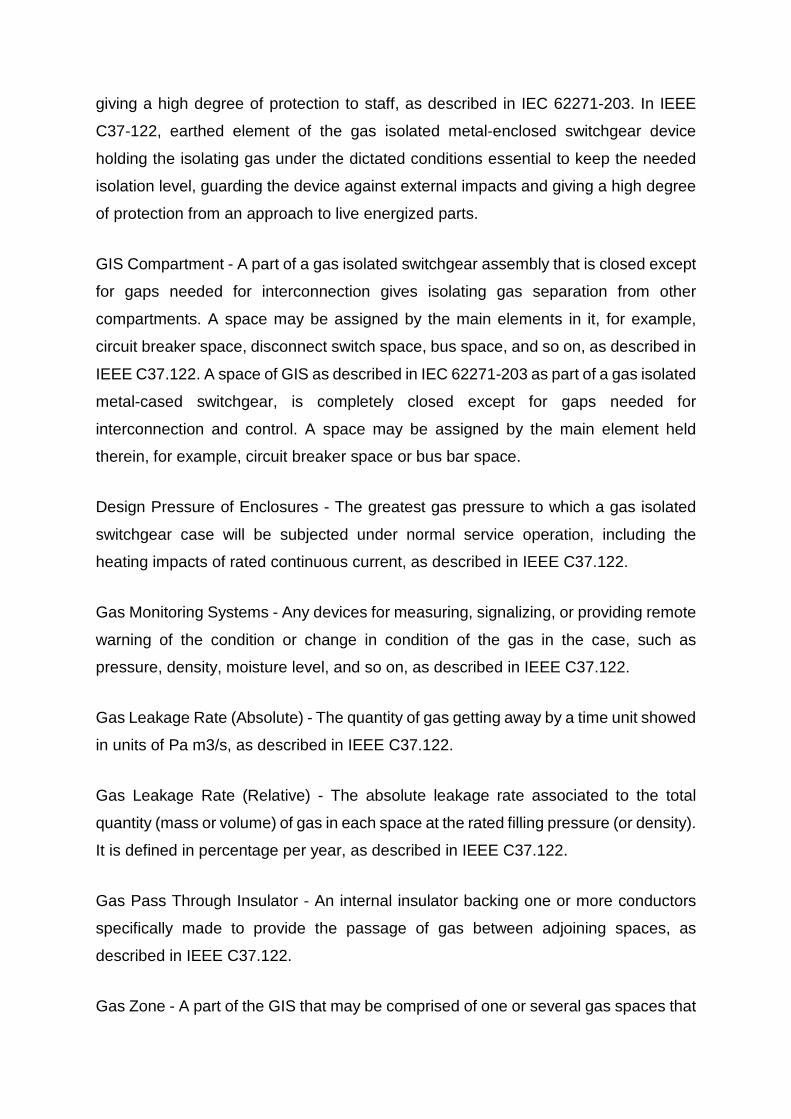
OPERATION PLATFORMS AND LADDERS
The great size of high voltage GIS typically at the 420 kV and 550 kV voltage levels
may require platforms and ladders put in for operation and servicing needs. For
instance, platforms or ladders may be required to verify the position of disconnect or
ground switch through the view port. Hence, platforms or ladders should be part of the
GIS structure.
These ladders and platforms have to be designed in such a way that safety is
guaranteed from an operational point. Platforms are typically fixed to the GIS while
ladders may be fixed or removable.
Figure 1. Ladders and platforms in GIS

GIS MONITORING ELEMENTS
Monitoring elements in GIS equipment should be made and put in such a way that
they can easily be identified either by color and/or numbering. Monitoring elements
are utilized for gas density reading and are put on the gas space. The older design of
utilizing gas pipes to link the gas compartment to a central gas density control cubicle
is disused since the raised risk of gas leaks from these pipes and their fittings.
In modern GIS technologies, gas density readers generally give only a red or green
indication. Green means all is “OK, no gas loss” and red means “not OK, gas loss”.
Switchgear will be automatically turned off by clearing the section from high voltage.
It is crucial that there is visible and clear marking of each gas space for the servicing
staff. This assures that the gas space can clearly be described between the two
gastight isolators of the gas compartment. Typically allots are sowed by outside
coloring.
Figure 2. Gas density monitoring indicator
Other monitoring elements include operation counter or UHF antennas for partial
discharge measure. Typically, when the GIS is in normal operation, it is not supervised
by partial discharge (PD) measure since it is not required. Nevertheless, at the
commissioning time, primarily at the greater voltage levels of 420 kV, 550 kV, or above,
an on-site temporary PD measuring is utilized. The PD measurement devices are then
linked to the UHF antennas of the GIS where safe access is required. After the
commissioning is completed, the PD measuring devices are disassembled.

THERMAL EXPANDING
When current is going through the GIS equipment the conductor temperature will rise
thus the enclosure temperature will increase. This can quickly arrive at temperature
differences of 40K to 50K and will end in a thermal expansion breakup of the enclosing
and conductor metallic materials. Thermal expansion forces are strong. To keep the
GIS from mechanical tensions induced by thermal expanding, bellows need to be
given to mechanically decouple the GIS bays. In the situation of direct transformer
links, bellows are also needed to mechanically decouple the GIS and the transformer.
The technical demands are presented in IEC 62271-211.
UNDERGROUND CABLE CONNECTION TO GIS EQUIPMENT
Direct link of an oil or solid isolated underground cable will require a special enclosing
joint to bridge the cable isolation to the gas isolation of the GIS equipment. This is the
reason isolator cones are used and they are isolated with SF6 gas on the GIS
equipment side and with oil or solid isolation fittings on the underground cable side.
The internal isolator cones are pressure equipment made to defy the GIS equipment
gas pressure, which is generally 0.6 MPa to 0.8 MPa. The copper conductor of the
underground cable and the aluminum conductor in the GIS equipment are linked by
an integrated conductor in the internal isolator cone. The outer enclosing is linked to
the underground cable shield or in some situations high voltage cable shielding is not
linked to the GIS equipment enclosure to avert induced currents in the cable shield,
which may heat up the underground cable. Another reason for isolating the
underground cable shield from the GIS equipment grounding is in the case of cathodic
corrosion protection of the underground cable. In these situations an isolating ring is
used at the GIS equipment.
If such isolation rings are utilized, in the situation of disconnector switching in the GIS
equipment, the generated high voltage transient over-voltages may induce lightning
flashovers across the insulation ring. This creates noises and light flashing and may
end in a staff accident.

Figure 3. Direct cable connection to GIS at 110 kV and single-phase insulated
Generally, the lightings are not dangerous for the GIS equipment or the underground
cable, but they are for staff around the GIS equipment. Hence, in such situations it is
advised to use surge arresters across the insulation ring to get around the high voltage
transients.
Due to the high frequency of the transient voltage of several hundred MHz, it is
essential to locate the surge arresters around the insulating ring. A minimum of four
arresters are advised.
GIS BUILDING REGULATIONS
Typically, GIS building demands and fire standards for buildings are adopted on
national or regional levels. The following demands and suggestions should be followed
for areas and areas around high voltage switchgear fabrications in line with IEEE
C37.122 and IC 62271-203.
LOAD AND CEILING
Modern GIS arrangements are handed over in large units. Generally, for the voltage
levels of up to 145 kV, two whole bays are shipped on-site. For voltages up to 420 kV,
one whole bay may be transported as well as anything above that, with elements of a
bay being added on site for assembly. In any situation, weights exceeding several
hundred kilograms or few tons have to be shipped on site in the building.
Hence, the GIS building ceilings and structure have to be sufficiently strong to support
the load. Moreover the floor material has to withstand the forces produced by fork
lifters or air lift equipment transporting the GIS bays. The weights have to be provided
by the GIS producer.
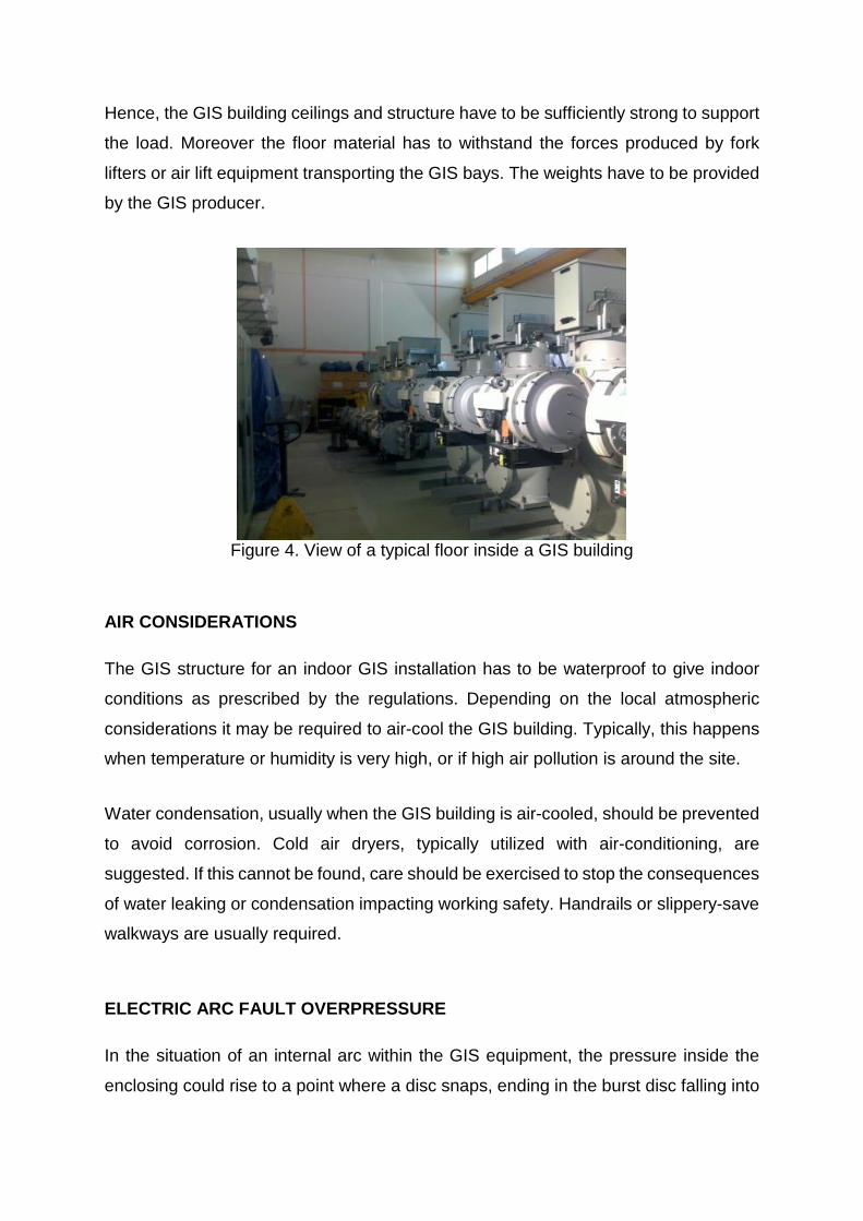
Figure 4. View of a typical floor inside a GIS building
AIR CONSIDERATIONS
The GIS structure for an indoor GIS installation has to be waterproof to give indoor
conditions as prescribed by the regulations. Depending on the local atmospheric
considerations it may be required to air-cool the GIS building. Typically, this happens
when temperature or humidity is very high, or if high air pollution is around the site.
Water condensation, usually when the GIS building is air-cooled, should be prevented
to avoid corrosion. Cold air dryers, typically utilized with air-conditioning, are
suggested. If this cannot be found, care should be exercised to stop the consequences
of water leaking or condensation impacting working safety. Handrails or slippery-save
walkways are usually required.
ELECTRIC ARC FAULT OVERPRESSURE
In the situation of an internal arc within the GIS equipment, the pressure inside the
enclosing could rise to a point where a disc snaps, ending in the burst disc falling into
the building space. GIS building wall, ceilings, and floors should be sufficiently strong
to properly withstand pressure growth. The pressure load depends on the enclosing
gas quantity and the short circuit rating of the devices and can be computed by the
GIS producer.
PIPELINES
If the case, water pipelines exist in the GIS building, they should be put in such a way
that they do not impact the GIS in case of failure.
BUILDING WALLS
The external building wall should be strong enough to resist rain, sun, wind, snow, and
ice to save the GIS equipment from environmental impact. The walk halls that connect
the indoor to outdoor GIS equipment should not impact the mechanical wall stability.
If metal elements are utilized for wall halls they have to be earthed. Panels or parts
that can be reached from the outside have to be mounted in such a way that they
cannot be displaced.
BUSILDING WINDOWS
GIS building external wall windows have to be made in such a way that any entry is
hard. Hence, the GIS building windows have to be placed more than 1.8 m above the
ground, in line with IEC 61936. The glass may be made up from unbreakable material
or the window guarded with an iron curtain.
GROUNDING/EARTHING DEMANDS
The very fast high frequency transients require a high frequency, low impedance to
ground/earth. This low impedance is achieved by having more links between the
concrete reinforcement steel grid and the grounding arrangement of the GIS building
at various locations in the GIS building floor. Common solutions for the GIS equipment
are to use a steel bar in the floor. At the GIS building wall more connections for the
GIS building to air bushing is required between the GIS enclosing and the building
wall. To stop good conductivity in the GIS building wall steel panels are typically
integrated with multiple links to ground/earthing of the GIS building. Secondary

devices utilized with the GIS equipment have to be properly designed and verified
about their resistance against transient over-voltages of the secondary circuits.
BURN THROUGH OF ENCLOSURE
GIS burn through safety includes gas detection, ventilation, and personal access. Care
has been exercised by type measurements of internal arcs in line with IEEE C37.122
and IEC 62271-203 to save staff and other devices.
OPERATION BEHIND PRESSURIZED ISOLATORS
Safety work directions to operate behind pressurized isolators are specified in
maintenance regulations between end user and producer.
SF6 RELEASE TO BUILDINGS
The regulations about safety to release SF6 into buildings are part of mutual agreement
between end user and producer. These regulations need to consider local standards
to avoid too low oxygen concentration in surrounding air and health issues of SF6 by-
products.

Figure 5. Ground/earth connection of GIS using bolts or a steel bar in the floor (a)
Bolted GIS fixing with grounding connection (b) Steel bar is the floor including
grounding connection
GIS GROUNDING AND BONDING
GIS equipment is inherently safe since all energized elements, with the exception of
SF6-to-air bushings terminals, are closed in earthed cases and are not subject to
incidental contact. Moreover, to assure staff safety and save devices, GIS installations
apply different earthing patters to achieve system and protective grounding.
GIS VS AIS GROUNDING
GIS equipment is established under the same system parameters as AIS equipment.
Nevertheless, with respect to earthing, one major difference is that GIS equipment is
typically established on much smaller sites than AIS equipment. Accordingly, GIS
equipment does not have the same benefits as large AIS switchyards where the
station ground grid assists to disperse fault currents. Hence, in order to secure low
impedance paths to ground for fault currents, decrease magnetic field magnitudes,
and reduce transient over-voltages, GIS arrangements use grounding arrangements
with multiple points. Multipoint earthing arrangements consist of short earthing
conductors that link the GIS equipment at various points along the enclosures. These
numerous earthing conductors allow for parallel paths to the GIS main earthing bus or
GIS earthing mesh.

GIS ENCLOSING CURRENTS
In most GIS arrangements, each element is electrically linked either via flange links or
external shunts. This ends in an uninterrupted enclosure throughout the GIS system,
granting enclosure currents to go during normal service and under fault situations.
Enclosure currents are an end result of voltages generated in the metallic case by
effects of currents passing through the enclosed conductors, and can be categorized
as induced, return, circulating, or fault currents.
During normal service, the return current on a GIS case can rise up to 90% of the
operating current. In the case three-phase fault happens, the return current can rise
up to 90% of fault currents. Hence, GIS return current conductors, flanges and shunts,
are made for a full return current and fault conditions without outperforming the
conductor’s thermal and mechanical boundaries.
Enclosure currents in three-phase GIS usages are not susceptible to circulating
enclosure currents since all phase conductors are placed inside one enclosure, and
the phase conductor’s electromagnetic fields cancel each other out.
In single-phase GIS arrangement, each conductor is placed within its own earthed
case. Consequently, enclosure currents during normal service are made up of
circulating currents. GIS producers generally supply conductors to link each single-
phase case at more locations. These earthing links are interconnected across each
phase case at intervals along the GIS equipment, as well as the ends of the cases to
promote circulating currents and decrease magnetic fields. The phase enclosing
interconnections also hold heavy circulating currents from going through earthing
conductors and into the substation earthing grid.
TYPICAL RULES FOR GIS EARTHING
As mentioned in IEEE Standard 80, touch voltages can be more severe than step
voltages in AIS equipment. With even more devices within reach in GIS, and induced
voltages present on GIS cases, management of touch voltages is even more important
in GIS equipment. To assess maximum touch and step voltages taking place on GIS
cases during a fault, it is essential to complete an assessment on the substation

earthing arrangement. Available earthing software should be utilized to complete
checks to assess maximum touch and step potentials and ground potential growth.
In typical GIS applications there are two earthing grids that make up the earthing
arrangement:
(1) the station earthing network, which is alike common AIS installation; (2) the GIS
earthing mesh, that is a narrowly separated earthing grid (commonly 3–5 meters)
implanted into the concrete slab in which the GIS equipment is put. A border earthing
conductor around the building or case links the two earthing grids. Short links between
the GIS cases and earthing mesh at intervals of around 10 meters, or in line with the
producer’s requirements, make up the multipoint earthing arrangement. Best patterns
for GIS earthing and bonding include the following:
1. All earthing conductors should be as short as possible.
2. The earthing mesh and links should be in a position of conduct the system’s fault
currents without violating the thermal and mechanical boundaries.
3. All exposed earthing conductors should be saved against mechanical destruction
and placed so as not to present a “trip hazard” to operation staff.
4. Adequate earthing and bonding methods, such as more conductors or voltage
limiters, are needed at all separations within the GIS equipment. This includes SF6
gas-to-air links, SF6 gas-to-cable links, SF6 gas-to-oil links, and where GIB exits the
building.
5. Make sure all metallic building spaces, GIS support structures, and GIS
maintenance platforms are adequately earthed.
6. Reinforcement steel in the GIS building floor should be linked to the GIS earthing
mesh to further match ground potentials.
7. All secondary cables should be shielded with both ends of each cable shield earthed
to mitigate potential electromagnetic interference.
VERY FAST TRANSIENTS IN GIS EQUIPMENT
Very fast transients are produced as an outcome of switching processes inside the
GIS equipment or a dielectric break that induces a voltage collapse within the GIS
equipment. The voltage break down generates traveling waves that spread away from
the disturbance. The traveling waves spread throughout the GIS equipment with
different reflections and mix to generate VFTs or over-voltages with a very steep rise
rate. VFTs can induce electromagnetic interference in the local environment and in
secondary circuits. As VFTs reach discontinuities, they can induce transient enclosure
voltages (i.e., TEVs). TEVs are not direct danger to staff, but may create electrostatic
sparks if the GIS multipoint earthing arrangement is not adequately placed.
GIS EARTHING CONNECTION DETAILS
- Each circuit breaker should have two earthing connection points.
- Special care should be given to SF6 gas-to-air bushings where high frequency
effects are dominant. A minimum of two earthing conductors should be placed.
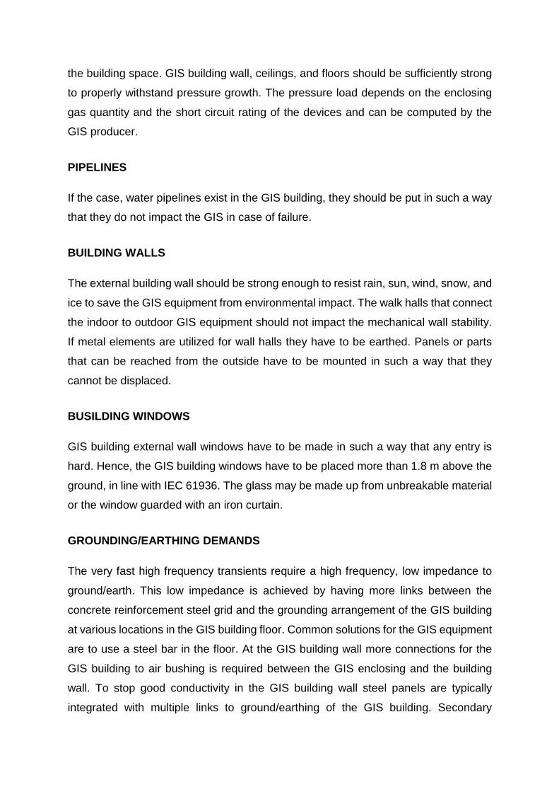
Figure 6. SF6 gas to air bushings

- It is crucial to assess the earthing method at the GIS cable end unit. More
conductors may be needed if directly bonded and voltage limiters have to be
taken into account if single point bonding is used.
- All steel structures have to be earthed. Typically, a steel structure can be
earthed to the nearest earthing point or GIS flange.
- GIS building slabs should include an imbedded GIS earthing mesh and steel
reinforcement should be concrete. Reinforced steel should be bonded to the
earthing mesh every 3 meters in both directions.
Figure 7. SF6 gas to cable connections
Figure 8. Steel structures
ELEMENTS FOR SELECTING GAS INSULATED SUBSTATIONS
The GIS substation development has been around world-wide for 60 years and GIS
technology is becoming dominant asset for substation end users. Utility companies,
government IPPs, military and industry are exposing many benefits of GIS.
Nevertheless, when deciding if to select mainstream AIS, GIS, or a combined-
technology solution there are many elements that have to be assessed. There is such
an abundance of information, which can be understood from several respects, that it
can make a user’s conclusion hard. As a matter of fact, the quantity of selection
standards for AIS and GIS can block a user’s decision-making process. Hence, once
a substation’s functional demands are determined, it is vital to find out, and even
measure, which factors are crucial to the user’s particular usage.
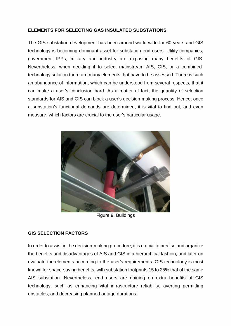
Figure 9. Buildings
GIS SELECTION FACTORS
In order to assist in the decision-making procedure, it is crucial to precise and organize
the benefits and disadvantages of AIS and GIS in a hierarchical fashion, and later on
evaluate the elements according to the user’s requirements. GIS technology is most
known for space-saving benefits, with substation footprints 15 to 25% that of the same
AIS substation. Nevertheless, end users are gaining on extra benefits of GIS
technology, such as enhancing vital infrastructure reliability, averting permitting
obstacles, and decreasing planned outage durations.

For a user substituting older infrastructure, upgrading disused arrangements,
expanding capacity or developing new capital, distinguishing the most pertinent
elements empowers the end user to decide on the optimal substation design. All
elements may not directly affect investment or life cycle prices, but may still be vital in
the choice of the substation location and construction design. Following section
presents typical terms and elements related to AIS and GIS substation evaluation:
- Aesthetics - Appearance factors and community adoption may have a dominant
impact on substation’s area, height, and visibility. Typically, AIS is more difficult
to disguise than GIS substation.
- Altitude - Elevation above sea-level, where devices that depend on air for its
isolating and cooling medium, will have a greater temperature growth and a
lower dielectric strength when serviced at greater altitudes. Both AIS and GIS
technologies may require adjustment based on real substation altitude.
- Atmospheric contamination - Airborne pollution, such as dust, debris, salt and
industrial pollution, can affect exposed electrical isolation. GIS equipment is
usually installed indoors. Moreover, most GIS elements are hermetically closed
inside an enclosure that makes GIS technology a superior solution in harsh
atmospheric conditions.
- Availability - The amount of time that the service is available and the probability
that power will be available.
- Audible noise - Sound levels generated by electrical devices may be an issue
to the public. Both AIS and GIS technology noise has to be assessed for the
user’s needs.
- Automation - Provisions for checking and supervising substation devices can
be local or remote. GIS technology may have more possibilities for control since
most circuit breakers are motor operated. Nevertheless, in GIS equipment
these functions are gathered inside local control cabinet (LCC) and have to be
incorporated with the user’s existing automation system.
- Capacity - A substation’s load-carrying capacity, typically with reference to a
power transformer’s rating and determined by a system load assessment. The
AIS and GIS switching devices have to be coordinated with the substation’s
capacity.
- Commissioning – Process that includes testing, inspection and documenting all
primary and secondary elements needed before putting a substation into
operation. Prefabricated and pretested GIS shipping elements can decrease
inspection and testing time.
- Construction - Prefabricated GIS shipping elements usually decrease field
installation prices and time. Nevertheless, prefabrication is typically less with
greater voltages, and many GIS are put indoors, which asks for building
construction.
- Community effect - Public concern of substation installations typically go around
aesthetics, land use, safety, environmental effects and electromagnetic field
(EMF) issues. GIS technology can be attracting when public approval is needed
due to its small size and power to blend with the surrounding environment.
- Cost - GIS technology is costlier than AIS devices. Nevertheless, consideration
of life cycle prices presents that GIS technology is less expensive and gives
better service. Price comparisons should be founded on the overall life cycle
prices, including devices, site development, land, normal servicing and
maintenance prices, and forced outage prices based on reliability.
- Cutovers (planned disconnections) - During substation commissioning, one of
the final steps is to transfer transmission lines and loads into the new
substation. GIS technology has a benefit over AIS technology due to its smaller
footprint and interface flexibility. Hence, many times GIS building can happen
closer to connection points and therefore decrease cutover durations.
- Environment – GIS technology inherently decreases land and space use
effects. Nevertheless, GIS equipment has more SF6 sealed elements and thus
gets more attention due to possible climate change effects. Despite this issue,

possible total contributions of SF6 to global atmosphere is miniscule relative to
carbon emissions.
- Emissions (SF6) - Extra treatment of SF6 gas is needed due to greater amounts
utilized in GIS. Since SF6 is a greenhouse gas, it requires to be adequately
handled.
- Expandability - AIS technology can be easily expanded. However, GIS
technology is a perfect solution for expanding AIS when there is limited space,
and planned outages are hard to get. Expanding existing GIS asks for the
original design to allow provisions for future upgrades and may at times demand
future infrastructure to be established early.
- EMF (electromagnetic field) - Magnetic fields due to conductor currents are
decreased by GIS case currents and are usually less than those of AIS
equipment. Even near GIS equipment, where greatest EMF levels can be
experienced, exposure levels are typically well within allowable limits.
Regarding public safety, evaluations have demonstrated EMF levels are
usually orders of magnitude below safe levels.
- Failure rate - The average failure number of an element or unit of the system in
a given time (typically a year). MTBFs are commonly less with GIS.
- Flexibility - The ease of servicing and time required to complete switching
functions within a substation. This change with AIS and GIS arrangements.
- Interruption - A surcease of service to one or more clients, whether energy was
being used or not. Interruptions can be assorted as instantaneous, temporary,
momentary or sustained.
- Initial capital - All initial prices related to land acquirement, construction,
licences, engineering design, civil construction, site work, purchase of devices,
training, and installation of a substation. This differs between AIS and GIS
arrangements, but AIS is usually less expensive.

- Land size. Property sizes are usually smaller when using GIS technology.
Nevertheless, if land is cheap at the given site, this may not be crucial
consideration.
- Location - Small GIS equipment footprints allow placing substations closer to
end users, eliminating permitting needs, setting off high land prices, and hiding
substation devices from the public.
- Life cycle cost - A price assessment that incorporates capital investment, land
purchase, site preparation, reliability effects, servicing, and maintenance
spending for the project life cycle with a defined interest rate. This method
allows for an assessment of the pertinent considerations, weighted by the end
user, to compute the overall life cycle price.
- Maintenance - Resources needed to upkeep substation devices. Frequency of
GIS care is much lower than AIS because most elements are saved from the
environment. Nevertheless, GIS maintenance processes ask for an extra
training and GIS replacement elements may not be as easily available.
- Operation and maintenance (O&M) - This price takes into account all the fixed
prices related to a substation, which are prices for property taxes, planned
operation and maintenance, insurance and anticipated interruptions.
- Permitting issues - Indoor GIS technology may need enclosure or building
licences, but complete permitting is typically sped up and/or decreased when
compared to AIS technology. In addition, GIS technology can reduce effects on
environmentally sensitive locations.
- Reliability - The part of time that an element or system is capable of completing
the required process. The probability that it will be in operation where it can
operate. The four crucial indicators for assessing reliability are SAIFI, CAIFI,
SAIDI, and CTAIDI.
- Restoration - The return of electric power after an interruption, because of
maintenance of the outage that caused the interruption, or because of re-

switching of the power, or the initiating an alternate power generator.
- Safety - Safety is crucial to substation design and demands protecting the
public, staff, by security, design, construction, training means and work
practices. It is also crucial to note that safety starts during the engineering and
equipment selection process.
- Security - A terror such as terrorism, vandalism or unauthorized persons getting
into the substation. Usually, threats are minimized with GIS because the
substation is placed indoors and energized elements are sealed.
- Seismic - The power of substation elements to resist forces produced by
earthquakes. GIS usually has better seismic capability than similar AIS.
- Site preparation - Site development that includes all earth work such as cut, fill,
grading, and drainage. GIS substations usually minimize the degree of earth
work and civil work.
- Soil conditions - Features of the surface where a substation will be placed.
These features will assist determine the foundation demands for the substation
devices. Detailed assessment of resources needed to develop the particular
site is suggested to decide if AIS or GIS technology is more useful.
- Stability - The power of an electrical system to return to a steady state after a
collapse.
- Unique elements - Capacity coupled voltage transformers (CCVTs), load break
switches and wave traps are typically not part of GIS installation. Such elements
are needed to be air-insulated once the circuit leaves the GIS.
- Weather - Elements such as wind, ice, storms, rain, temperature, snow, and
humidity may impact a substation’s service. GIS technology tends to resist
extreme environmental effects since it can be put indoors and GIS elements
are hermetically closed inside cases.

- Staff training - Resources needed training the staff the correct processes of
operating and handling substation devices. GIS asks for additional training.
Previously mentioned considerations for selecting AIS or GIS technology can be
classified into three major groups: power system demands, such as reliability and
availability; environment, such as place and climate; and financing, with respect to
installation, operation and maintenance. Also, these considerations can be further
classified as quantitative or qualitative since some are more easily quantified than
others.
POWER SYSTEM CONSIDERATIONS
Considerations for selecting AIS or GIS technology start to come along in the asset
planning stage. Once power system or transmission planning has decided the
requirement for a retrofit or green-field substation, different elements have already
been assessed, such as system stability, reliability, and load flow needs. The
possibility to choose AIS or GIS technology at this point may be early, but data made
during the planning process may already start guiding the user and investor to a
suggested solution.
ENVIRONMENT CONSIDERATIONS
Locations with harsh conditions, such as poor soil, great air pollution, high seismic, or
storm surge, are possible considerations created by the natural environment of a
potential substation location. Nevertheless, other qualitative elements associated to
the environment, such as aesthetics to the local district, licensing issues, and/or urban
area effects can play into the optimal substation solution.
ECONOMIC CONSIDERATIONS
Economic assessment of an asset depends on the importance a substation user gives
to each determining element. Also, dominating elements can change with each
substation usage. Hence, in order to comprehend the complete investment of a
substation project, many end users are turning to life cycle cost assessment. This
assessment provides the user with data on how much a substation will cost over the
lifetime of the devices. When AIS is cross compared to GIS technology with respect

to the upfront investment price, most of the time AIS technology will result in the least
expensive answer. Nevertheless, factoring in land purchase, licensing, site
preparation, and O&M prices, gives a more holistic approach and may alter the optimal
substation solution.
Innovation or non-traditional designs, such as GIS technology, can provide more
reliability for the same budget under the right considerations. That is why it is vital for
traditional engineering techniques, such as N-1 assessment, to be highlighted with a
reliability-based life cycle cost planning approach.
CONCLUSION
When determining between AIS or GIS technology, some elements alone, for example
aesthetics, may be an overcoming impact on a user’s conclusion. Nevertheless, most
of the time the best conclusion asks for assessing many elements and soliciting input
data from many sections within an investor’s organization. It is also critical to note that
the optimal substation arrangement may not be solely AIS or GIS. Sometimes a mix
of the two (i.e., hybrid or mixed-technology) might be the best arrangement. Typically,
most of the factors will prefer GIS technology, but it is the value or importance given
to the considerations that decides if the return on investment is justifiable to choose
GIS over AIS technology. Consideration that can be measured should be assigned
importance weights based on the user’s needs.