Embed Size (px)
Citation preview
Reference numberISO 4706-1:2008(E)
© ISO 2008
INTERNATIONAL STANDARD
ISO4706-1
First edition2008-04-15
Gas cylinders — Refillable welded steel cylinders — Part 1: Test pressure 60 bar and below
Bouteilles à gaz — Bouteilles en acier soudées rechargeables —
Partie 1: Pression d'essai de 60 bar et moins
ISO 4706-1:2008(E)
PDF disclaimer This PDF file may contain embedded typefaces. In accordance with Adobe's licensing policy, this file may be printed or viewed but shall not be edited unless the typefaces which are embedded are licensed to and installed on the computer performing the editing. In downloading this file, parties accept therein the responsibility of not infringing Adobe's licensing policy. The ISO Central Secretariat accepts no liability in this area.
Adobe is a trademark of Adobe Systems Incorporated.
Details of the software products used to create this PDF file can be found in the General Info relative to the file; the PDF-creation parameters were optimized for printing. Every care has been taken to ensure that the file is suitable for use by ISO member bodies. In the unlikely event that a problem relating to it is found, please inform the Central Secretariat at the address given below.
COPYRIGHT PROTECTED DOCUMENT © ISO 2008 All rights reserved. Unless otherwise specified, no part of this publication may be reproduced or utilized in any form or by any means, electronic or mechanical, including photocopying and microfilm, without permission in writing from either ISO at the address below or ISO's member body in the country of the requester.
ISO copyright office Case postale 56 • CH-1211 Geneva 20 Tel. + 41 22 749 01 11 Fax + 41 22 749 09 47 E-mail [email protected] Web www.iso.org
Published in Switzerland
ii © ISO 2008 – All rights reserved
ISO 4706-1:2008(E)
© ISO 2008 – All rights reserved iii
Contents Page
Foreword............................................................................................................................................................ iv Introduction ........................................................................................................................................................ v 1 Scope ..................................................................................................................................................... 1 2 Normative references ........................................................................................................................... 1 3 Terms, definitions and symbols.......................................................................................................... 2 4 Inspection and testing.......................................................................................................................... 4 5 Materials ................................................................................................................................................ 4 6 Design .................................................................................................................................................... 5 7 Calculation of minimum wall thickness (sidewall and ends) ........................................................... 6 8 Construction and workmanship........................................................................................................ 11 9 Testing ................................................................................................................................................. 16 10 Acceptance criteria............................................................................................................................. 21 11 Technical requirements for new design type approval .................................................................. 26 12 Markings .............................................................................................................................................. 27 13 Certificate ............................................................................................................................................ 27 Annex A (normative) Manufacturer's markings for LPG.............................................................................. 28 Annex B (informative) New design type approval certificate....................................................................... 29 Annex C (informative) Acceptance certificate ............................................................................................... 30 Bibliography ..................................................................................................................................................... 32
ISO 4706-1:2008(E)
iv © ISO 2008 – All rights reserved
Foreword
ISO (the International Organization for Standardization) is a worldwide federation of national standards bodies (ISO member bodies). The work of preparing International Standards is normally carried out through ISO technical committees. Each member body interested in a subject for which a technical committee has been established has the right to be represented on that committee. International organizations, governmental and non-governmental, in liaison with ISO, also take part in the work. ISO collaborates closely with the International Electrotechnical Commission (IEC) on all matters of electrotechnical standardization.
International Standards are drafted in accordance with the rules given in the ISO/IEC Directives, Part 2.
The main task of technical committees is to prepare International Standards. Draft International Standards adopted by the technical committees are circulated to the member bodies for voting. Publication as an International Standard requires approval by at least 75 % of the member bodies casting a vote.
Attention is drawn to the possibility that some of the elements of this document may be the subject of patent rights. ISO shall not be held responsible for identifying any or all such patent rights.
ISO 4706-1 was prepared by Technical Committee ISO/TC 58, Gas cylinders, Subcommittee SC 3, Cylinder design.
This first edition of ISO 4706-1, together with ISO 4706-2, cancels and replaces ISO 4706:1989, which has been technically revised.
ISO 4706 consists of the following parts, under the general title Gas cylinders — Refillable welded steel cylinders:
⎯ Part 1: Test pressure 60 bar and below
⎯ Part 2: Test pressure greater than 60 bar
This Part of ISO 4706 has been prepared to address the general requirements in Chapter 6.2 of the UN model regulations for the transportation of dangerous goods ST/SG/AC.10/1/Rev.15. It is intended to be used under a variety of regulatory regimes but has been written so that it is suitable for use with the conformity assessment system in 6.2.2.5 of ST/SG/AC.10/1/Rev.15.
ISO 4706-1:2008(E)
© ISO 2008 – All rights reserved v
Introduction
The purpose of this part of ISO 4706 is to facilitate agreement on the design and manufacture of welded-steel gas cylinders in all countries. The requirements are based on knowledge of, and experience with, materials, design requirements, manufacturing processes and controls in common use for the manufacture of gas cylinders.
With respect to those aspects concerning construction materials, approval of design rules and inspection during manufacture, which are subject to national or international regulations, it is necessary for interested parties to ensure that in the practical application of this part of ISO 4706, the requirements of the relevant authority are also satisfied.

INTERNATIONAL STANDARD ISO 4706-1:2008(E)
© ISO 2008 – All rights reserved 1
Gas cylinders — Refillable welded steel cylinders —
Part 1: Test pressure 60 bar and below
1 Scope
This part of ISO 4706 specifies the minimum requirements concerning material selection, design, construction and workmanship, procedure and test at manufacture of refillable welded-steel gas cylinders of a test pressure not greater than 60 bar1), and of water capacities from 0,5 l up to and including 500 l exposed to extreme worldwide temperatures (−50 °C to +65 °C) used for compressed, liquefied or dissolved gases.
Transportable large cylinders of water capacity above 150 l and up to 500 l may be manufactured and certified to this International Standard provided handling facilities are provided (see 8.6.4).
This International Standard is primarily intended to be used for industrial gases other than Liquefied Petroleum Gas (LPG), but may also be applied for LPG. For specific LPG applications see ISO 22991.
2 Normative references
The following referenced documents are indispensable for the application of this document. For dated references, only the edition cited applies. For undated references, the latest edition of the referenced document (including any amendments) applies.
ISO 4136, Destructive tests on welds in metallic materials — Transverse tensile test
ISO 5817, Welding — Fusion-welded joints in steel, nickel, titanium and their alloys (beam welding excluded) – Quality levels for imperfections
ISO 6892, Metallic materials — Tensile testing — Method of testing at ambient temperature
ISO 7438, Metallic materials — Bend test
ISO 9606-1, Qualification test of welders — Fusion welding — Part 1: Steels
ISO 10297:2006, Transportable gas cylinders — Cylinder valves — Specification and type testing
ISO 11117, Gas cylinders — Valve protection caps and valve guards — Design, construction and tests
ISO 13769, Gas Cylinders — Stamp marking
ISO 11622, Gas cylinders — Conditions for filling gas cylinders
ISO 15613, Specification and qualification of welding procedures for metallic materials — Qualification based on pre-production welding test
1) 1 bar = 105 Pa = 105 N/m2.
ISO 4706-1:2008(E)
2 © ISO 2008 – All rights reserved
ISO 15614-1, Specification and qualification of welding procedures for metallic materials — Welding procedure test — Part 1: Arc and gas welding of steels and arc welding of nickel and nickel alloys
ISO 17636, Non-destructive testing of welds — Radiographic testing of fusion-welded joints
ISO 17637, Non-destructive testing of welds — Visual testing of fusion-welded joints
ISO 17639, Destructive tests on welds in metallic materials — Macroscopic and microscopic examination of welds
ISO 22991, Gas Cylinders — Transportable refillable welded steel cylinders for liquefied petroleum gas (LPG) — Design and construction
3 Terms, definitions and symbols
3.1 Terms and definitions
For the purposes of this document, the following terms and definitions apply.
3.1.1 yield strength value corresponding to the upper yield strength, ReH, or, for steels when yielding does not occur at tensile testing, the 0,2 % proof stress (non-proportional elongation), Rp0,2
3.1.2 normalizing heat treatment in which a cylinder is heated to a uniform temperature above the upper critical point (Ac3) of the steel to regenerate or homogenize the metallurgical structure of the steel, to a sufficient degree to achieve the desired mechanical properties, and then cooled in a controlled or still air atmosphere
3.1.3 stress relieving heat treatment given to the cylinder, the object of which is to reduce the residual stresses without altering the metallurgical structure of the steel, by heating it to a uniform temperature below the lower critical point (Ac1) of the steel, then cooling it in a controlled or still air atmosphere
3.1.4 stabilizing heat treatment given to the cylinder, the object of which is to stabilize the structure of the steel by heating it to a uniform temperature above the lower critical point (Ac1) of the steel and subsequently cooling it to obtain the desired mechanical properties
3.1.5 batch quantity of cylinders made consecutively by the same manufacturer using the same manufacturing techniques, to the same design, size and material specifications using the same type of welding machines, welding procedures and to the same heat treatment conditions
NOTE 1 In this context, “consecutively” need not apply to continuous production (start to finish).
NOTE 2 See 10.2 for specific batch quantities.
3.1.6 base materials steel used to manufacture the cylinder including the pressure and non-pressure retaining materials of construction
ISO 4706-1:2008(E)
© ISO 2008 – All rights reserved 3
3.1.7 cylinder shell cylinder after completion of all forming, welding and heat treatment operations
3.1.8 F Factor design stress factor
3.1.9 parent material all pressure retaining materials used in the fabrication of the cylinder
3.1.10 overlap placement of steel on top of or below a weld joint for the purpose of joint alignment or added joint strength
3.2 Symbols
Symbol Definition Unit
a Calculated minimum thickness of the cylindrical shell mm
a1 Calculated minimum value of a used in the calculation of b (see 7.2.2) of the cylinder head
—
ab Minimum thickness of the cylindrical shell (including any corrosion allowance) guaranteed by the manufacturer
mm
A Percentage elongation after fracture %
Y Stabilized cylinder —
b Calculated minimum thickness of the end mm
C Shape factor —
D Outside diameter of the cylinder as given in the design drawing mm
Df Outside diameter of a bend test former mm
F Design stress factor —
h Height of the cylindrical part of the end mm
H Outside height of the domed part of the end mm
J Stress reduction factor —
K Ellipsoidal Ratio —
L Length of the cylinder mm
L0 Original gauge length in accordance with ISO 6892 mm
n Ratio of diameter of bend test former to the thickness of the test piece —
N Normalized cylinder —
Pb Maximum pressure attained during the burst test bar
ISO 4706-1:2008(E)
4 © ISO 2008 – All rights reserved
Ph Actual test pressure applied to the cylinder by the manufacturer bar
Ptmin Minimum test pressure (see ISO 11622) bar
r Inside knuckle radius of the end mm
R Inside dishing radius of the end mm
ReH Minimum value of yield strength (apparent) guaranteed by the cylinder manufacturer for the finished cylinder
N/mm2
Rg Guaranteed tensile strength by the manufacturer N/mm2
Rm Actual value of tensile strength determined by the tensile test specified in 9.1.2.2 N/mm2
Rp0,2 0,2 % proof stress (see ISO 6892) N/mm2
S Stress relieved cylinder —
S0 Original cross-sectional area of tensile test piece in accordance with ISO 6892 mm2
4 Inspection and testing
To ensure that the cylinders are in conformance with this part of ISO 4706, they shall be subject to inspection and testing in accordance with Clauses 7, 8, 9 and 10.
Some countries of use may require that cylinders be inspected and tested by an authorized body. The inspection body shall be recognized in the country of use and shall be competent for testing and inspecting cylinders in accordance with this International Standard.
5 Materials
5.1 The material used for the fabrication of the gas cylinder shall be steel, other than rimming quality, suitable for pressing or drawing and welding, and shall not deteriorate with time. The steel grades used shall have specified, guaranteed, mechanical properties that are possible to achieve for the finished cylinder after normalizing, stress relieving or stabilizing.
In cases where verification of this non-ageing property is required, the criteria by which it is to be specified should be agreed by the manufacturer and purchaser, and included in the order.
5.2 Materials for shells and end pressings, excluding bosses (see 5.3), shall conform to the requirements of 5.8 and 5.9.1.
5.3 Bosses shall be manufactured from compatible weldable materials with a maximum carbon content of 0,25 %(m/m).
5.4 All items welded to the cylinder (e.g. shrouds and footrings) shall be made of compatible weldable material containing maximum values %(m/m) of:
a) carbon 0,250 %;
b) phosphorous 0,040 %;
c) sulphur 0,040 %.
5.5 The welding consumables shall be such that they are capable of giving consistent welds with a minimum tensile strength at least equal to that specified for the parent materials in the finished cylinder.
ISO 4706-1:2008(E)
© ISO 2008 – All rights reserved 5
5.6 The cylinder manufacturer shall have certificates of the ladle analysis and mechanical properties of the steel supplied for the construction of the pressure retaining parts of the cylinder. The cylinder manufacturer shall also have certificates of the ladle analysis for items welded to the cylinder (e.g. shrouds and footrings).
5.7 A system of identification shall be in place to determine the cast(s) of steel used for the construction of the pressure retaining parts of the cylinder.
5.8 Grades of steel used for cylinder manufacture shall be compatible with the intended gas service (e.g. corrosive or embrittling gases).
5.9 Chemical composition.
5.9.1 Materials used for the fabrication of gas cylinders shells and end pressings shall be of weldable quality and values %(m/m) of:
a) carbon 0,25 %;
b) silicon 0,45 %;
c) manganese 1,60 %;
d) phosphorus 0,040 %;
e) sulphur 0,040 %;
shall not be exceeded in the cast analysis.
The use of micro-alloying elements such as niobium (columbium), titanium and vanadium shall not exceed:
a) niobium 0,05 %;
b) titanium 0,03 %;
c) vanadium 0,10 %;
d) niobium plus vanadium 0,12 %.
Where other micro-alloying elements are used, their presence and amounts shall be reported, together with those already described in 5.9.1, in the steel manufacturer’s certificate.
5.9.2 When the country of use of the cylinder requires a check analysis on the steel, the analysis shall be carried out either on specimens taken during manufacture from material in the form as supplied by the steel maker to the cylinder manufacturer, or from the cylinder shell, or from finished cylinders. In any check analysis, the maximum tolerance for cast analyses shall conform to the values specified in 5.9.1.
6 Design
6.1 General requirements
6.1.1 The calculation of the wall thickness of the pressure parts to resist the internal pressure in the gas cylinders is related to the yield strength of the material for the finished cylinder.
6.1.2 For calculation purposes, the value of the yield strength Re is limited to a maximum value of:
a) 0,75 Rg for finished cylinders with a guaranteed tensile strength (Rg) < 490 N/mm2;
b) 0,85 Rg finished cylinders with a guaranteed tensile strength (Rg) W 490 N/mm2.
ISO 4706-1:2008(E)
6 © ISO 2008 – All rights reserved
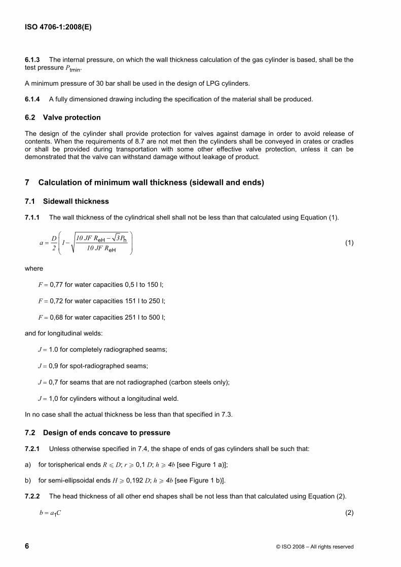
6.1.3 The internal pressure, on which the wall thickness calculation of the gas cylinder is based, shall be the test pressure Ptmin.
A minimum pressure of 30 bar shall be used in the design of LPG cylinders.
6.1.4 A fully dimensioned drawing including the specification of the material shall be produced.
6.2 Valve protection
The design of the cylinder shall provide protection for valves against damage in order to avoid release of contents. When the requirements of 8.7 are not met then the cylinders shall be conveyed in crates or cradles or shall be provided during transportation with some other effective valve protection, unless it can be demonstrated that the valve can withstand damage without leakage of product.
7 Calculation of minimum wall thickness (sidewall and ends)
7.1 Sidewall thickness
7.1.1 The wall thickness of the cylindrical shell shall not be less than that calculated using Equation (1).
eH h
eH
10 JF R 3PDa 1 2 10 JF R
⎛ ⎞−⎜ ⎟= −⎜ ⎟⎝ ⎠
(1)
where
F = 0,77 for water capacities 0,5 l to 150 l;
F = 0,72 for water capacities 151 l to 250 l;
F = 0,68 for water capacities 251 l to 500 l;
and for longitudinal welds:
J = 1.0 for completely radiographed seams;
J = 0,9 for spot-radiographed seams;
J = 0,7 for seams that are not radiographed (carbon steels only);
J = 1,0 for cylinders without a longitudinal weld.
In no case shall the actual thickness be less than that specified in 7.3.
7.2 Design of ends concave to pressure
7.2.1 Unless otherwise specified in 7.4, the shape of ends of gas cylinders shall be such that:
a) for torispherical ends R u D; r W 0,1 D; h W 4b [see Figure 1 a)];
b) for semi-ellipsoidal ends H W 0,192 D; h W 4b [see Figure 1 b)].
7.2.2 The head thickness of all other end shapes shall be not less than that calculated using Equation (2).
1b a C= (2)
ISO 4706-1:2008(E)
© ISO 2008 – All rights reserved 7
where
a1 is the value of a calculated in accordance with 7.1.1 using J = 1,0;
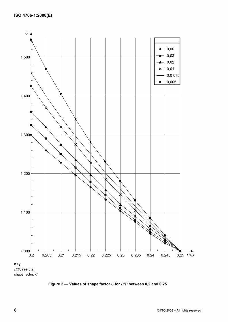
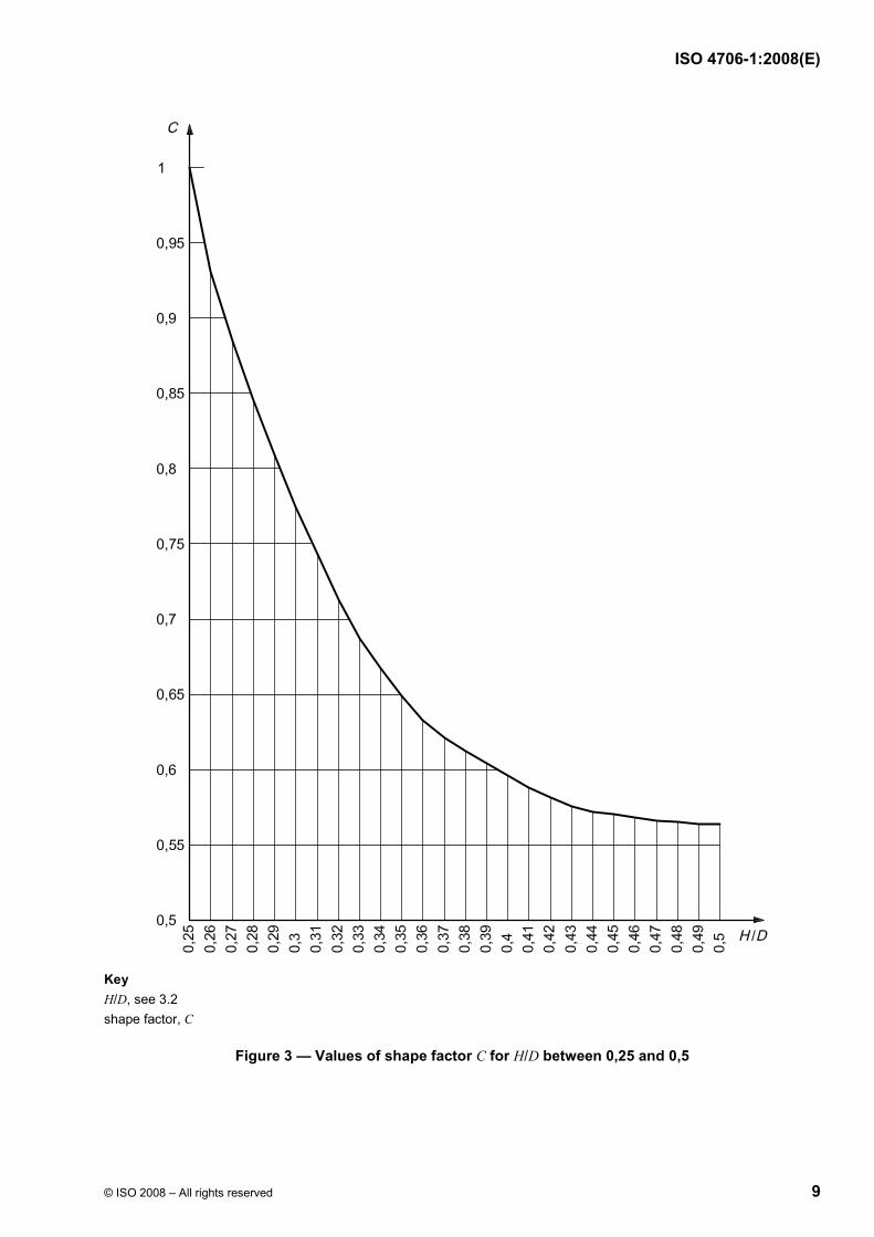
C is a shape factor, the value of which depends on the ratio H/D.
The value of C shall be obtained from the graph shown in Figure 2 or 3, as applicable.
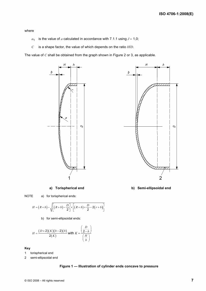
a) Torispherical end b) Semi-ellipsoidal end
NOTE a) for torispherical ends:
( ) ( ) ( ) ( )22 2D DH R b R b R b r b⎡ ⎤ ⎡ ⎤
= + − + − × + + − +⎢ ⎥ ⎢ ⎥⎣ ⎦ ⎣ ⎦
b) for semi-ellipsoidal ends:
( ) ( ) ( ) ( )( )
2 22
D K b bH
K+ −
= with K = 2D
bHb
⎛ ⎞⎜ ⎟−⎝ ⎠⎛ ⎞⎜ ⎟⎝ ⎠
Key 1 torispherical end 2 semi-ellipsoidal end
Figure 1 — Illustration of cylinder ends concave to pressure
ISO 4706-1:2008(E)
8 © ISO 2008 – All rights reserved
Key H/D, see 3.2 shape factor, C
Figure 2 — Values of shape factor C for H/D between 0,2 and 0,25
ISO 4706-1:2008(E)
© ISO 2008 – All rights reserved 9
Key H/D, see 3.2 shape factor, C
Figure 3 — Values of shape factor C for H/D between 0,25 and 0,5
ISO 4706-1:2008(E)
10 © ISO 2008 – All rights reserved
7.2.3 Heads that do not contain markings may be 90 % of the minimum sidewall thickness as indicated in 7.1.1 and 7.2.2.
Ends shaped other than those specified in 7.2 may be used provided that the adequacy of their design is demonstrated by fatigue testing in accordance with the requirements of 9.6.
For heads convex to pressure, the minimum head thickness shall be a minimum of two times that specified in 7.2.2.
7.3 Minimum wall thickness
7.3.1 The minimum wall thickness of the cylindrical shell a, and of the end, b, shall not be less than the value derived from any of Equations (3), (4) and (5).
for D < 100 mm:
amin = bmin = 1,1 mm (3)
for 100 u D u 150 mm:
amin = bmin = 1,1 + 0,008(D − 100) mm (4)
for D > 150 mm:
amin = bmin = (D/250) + 0,7 mm (with an absolute minimum of 2,0 mm) (5)
For acetylene cylinders with D > 300 mm the minimum wall thickness shall be 3,0 mm.
7.3.2 Equation 1 (see 7.1.1) is not applicable where the length of the cylindrical portion of the cylinder, measured between the beginning of the domed parts of the two ends, is not more than 2 .bD In this case the wall thickness shall be not less than that of the domed part (see 7.2.2).
7.4 Design of openings
7.4.1 The location of all openings shall be restricted to the ends of the cylinder.
7.4.2 Each opening in the cylinder shall be reinforced, either by a valve boss or pad, of weldable and compatible steel, securely attached by welding and so designed as to be of adequate strength and to result in no harmful stress concentrations. Compliance shall be confirmed by calculation or performing a fatigue test in accordance with the requirements of 9.6.
7.4.3 The welds of the openings shall be clear of circumferential and longitudinal joints.
7.4.4 If the leak-tightness between the valve and the cylinder is assured by a metallic seal (e.g. copper), a suitable internal valve boss can be fitted to the cylinder by a method that need not independently assure leak-tightness.
ISO 4706-1:2008(E)
© ISO 2008 – All rights reserved 11
8 Construction and workmanship
8.1 Quality conformance system
Each cylinder manufacturing facility should have a written quality system that meets the requirements of ISO/TR 14600.
8.2 Welding qualification
8.2.1 General
a) before proceeding with the production of a given design, all welding operators and welding procedures shall be approved by meeting the requirements of 8.2.2 to 8.2.9, ISO 9606-1, ISO 15613 or ISO 15614-1;
b) records of both qualifications shall be kept on file by the manufacturer;
c) weld approval tests shall be made in such a manner that the welds shall be representative of those made in production;
d) welders shall have passed the approval tests for the specific type of work and procedure specification concerned.
8.2.2 Base materials (pressure and non-pressure)
Base materials defined in the procedure specification shall be the same as the given design and those tested by the welders.
8.2.3 Positions of welds
For welder qualification, the position of the part for welding shall be as specified in 8.2.1 c).
8.2.4 Welding materials
Weld consumables (see 5.5) shall be the same as those specified in the procedure specification, those tested by the welders and those used for production.
8.2.5 Retesting
Where a welder fails to meet the requirements of a weld test:
a) an immediate retest may be made of two test welds of the type that failed, both of which shall meet all the test requirements; or
b) a retest may be made provided there is evidence that the operator has had further training and practice in the design and procedure specification.
8.2.6 Period of effectiveness
a) a welder shall be re-qualified if the design has not been produced by the welder for a period of three months or more;
b) records of welder effectiveness shall be retained by the manufacturer.
ISO 4706-1:2008(E)
12 © ISO 2008 – All rights reserved
8.2.7 Essential variables of the welding process
The procedure specification and welder qualification shall be set-up and tested when there is:
a) a change to the base materials used;
b) a change to the welding material used;
c) a change to the weld process;
d) a change to the weld position;
e) a decrease of 30 °C or more in the minimum specified preheating temperature;
f) a change from one heat treatment process to another (see 3.1.2, 3.1.3 and 3.1.4);
g) the omission or addition of a backing strip in single pass welds;
h) a change from multiple pass to single pass per side;
i) a change from a single arc to multi arc, or vice versa;
j) a change to the shielding gas or to the composition of the shielding gas (if there is a greater than 15,0 % change in the mixture).
8.2.8 Welder qualification tests
When required, the weldment shall, prior to radiography:
a) for longitudinal welds pass:
1) a bend test of the weld root;
2) a weld tensile test;
b) for circumferential welds pass:
1) a bend test of the weld root;
2) a weld tensile test;
c) for threaded connections to heads or bottoms pass macro tests, 180° apart;
d) for welded attachments, foot rings, collars or lugs, pass a macro test;
e) for fillet welds used for the attachment of bottom heads [see Figure 4 b)], pass macro tests, 180° apart.
8.2.9 Results
For radiography (see 9.4.1):
a) for bend tests:
upon completion of the test, the test piece (weld metal and parent material) shall remain uncracked;
ISO 4706-1:2008(E)
© ISO 2008 – All rights reserved 13
b) for tensile tests:
the tensile strength (Rm) value obtained, shall not be less than that guaranteed by the cylinder manufacturer (Rg) regardless of the fracture location;
c) for macro tests:
the etched specimen shall be visually examined to determine adequate root penetration into both members as to the established design.
8.3 Plates and pressed parts
Before assembly, the pressure parts of the cylinders shall be visually examined for cracks, seams, laminations, galling and freedom from any defects that may ultimately affect cylinder integrity.
8.4 Welded joints
8.4.1 The welding of two-piece cylinder circumferential joints or three-piece cylinder longitudinal and circumferential joints (pressure envelope) shall be by using a fully mechanized, semi-automatic or automatic process to provide consistent and reproducible weld quality.
8.4.2 The longitudinal joint, of which there shall be no more than one, shall be of the butt-welded type.
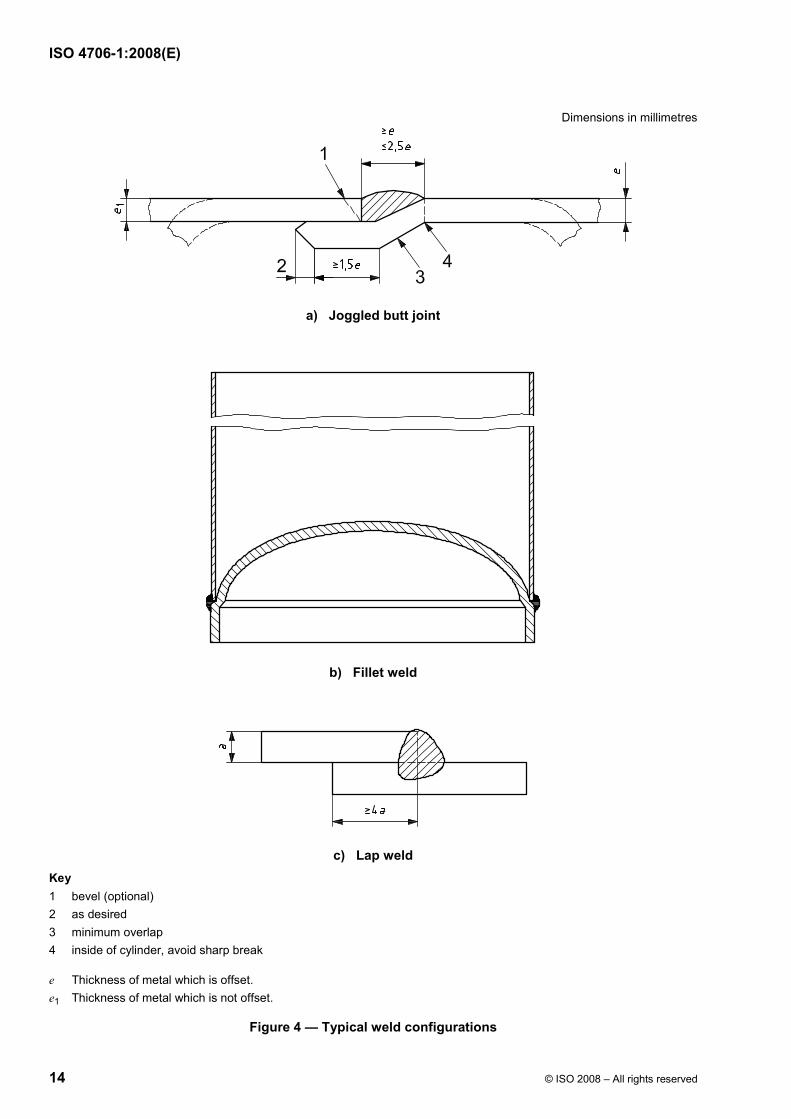
8.4.3 Circumferential joints, of which there shall be no more than two, shall be butt welded, butt welded with one member offset to form an integral backing strip {i.e. joggled [see Figure 4 a)]}, or fillet welded [see Figure 4 b)] or lap welded [see Figure 4 c)].
Lap-welded joints shall have a minimum overlap of four times the minimum design thickness (a).
8.4.4 Before cylinders are closed, longitudinal welds shall be visually examined from both sides in accordance with the requirements of ISO 17637.
Permanent backing strips shall not be used with longitudinal welds.
8.4.5 The fusion of the welded metal with the parent metal (pressure joint) for longitudinal seams, circumferential seams and bosses shall be smooth and free from undercutting or abrupt irregularity. There shall be no cracks, notching or porous patches in the welded surface and/or the surface adjacent to the weld. The welded surface shall be regular and even without concavity.
8.4.6 Butt welds shall have full penetration. The excess thickness shall be such that the weld integrity is not compromised.
8.4.7 Joggled butt welds shall have adequate penetration verified by bend testing and tensile testing. If adequate material is not available due to the cylinder geometry, the weld shall be verified by macro etch.
8.4.8 Lap welds shall have adequate penetration verified by macro etch and bend testing.
8.4.9 Fillet welds shall exhibit root penetration verified by macro etch.
8.4.10 The fusion of the welded metal with the non-pressure retaining attachments (e.g. shrouds and footrings) shall be smooth and free from abrupt irregularity. There shall be no cracks, notching or porous patches in the welded surface and/or the surface adjacent to the weld. The welded surface shall be regular and even, without concavity.
ISO 4706-1:2008(E)
14 © ISO 2008 – All rights reserved
Dimensions in millimetres
a) Joggled butt joint
b) Fillet weld
c) Lap weld Key 1 bevel (optional) 2 as desired 3 minimum overlap 4 inside of cylinder, avoid sharp break
e Thickness of metal which is offset. e1 Thickness of metal which is not offset.
Figure 4 — Typical weld configurations
ISO 4706-1:2008(E)
© ISO 2008 – All rights reserved 15
8.5 Tolerances
8.5.1 Out of roundness
The out of roundness of the cylindrical shell shall be limited so that the difference between the maximum and the minimum outside diameters in the same cross section is not more than:
a) for two-piece cylinders, 1 % of the mean of the diameters; and
b) for three-piece cylinders 1,5 % of the mean of the diameters.
8.5.2 Straightness
Unless otherwise shown on the manufacturer’s drawing, the maximum deviation of the cylindrical part of the shell from a straight line shall not exceed 0,3 % of the cylindrical length.
8.5.3 Verticality
When the cylinder is standing on its base, the deviation from vertical shall not exceed 1 % including the shroud and footring.
8.6 Non-pressure-containing attachments
8.6.1 Where non-pressure-containing attachments are to be attached to the cylinder by welding, such attachments shall be made of compatible weldable steel.
8.6.2 Attachments shall be designed to permit inspection of welds, which shall be clear of longitudinal and circumferential joints, and so designed as to avoid trapping water.
8.6.3 Where a footring is fitted, it shall be of adequate strength to provide stability and be attached so that it does not prevent inspection of any pressure-containing welds.
All footrings shall be designed to permit drainage and ventilation.
8.6.4 Depending on the geometry of the cylinder and the surrounding conditions, vessels of water capacity greater than 150 l shall require specific mechanical or other handling and transportation equipment (e.g. fork lift truck).
The cylinder itself shall have a suitable provision for such a lift to be made (e.g. lugs welded onto the top dome area of the cylinder and/or slots underneath the cylinder) where the forks of a fork lift truck can be engaged.
8.7 Valve protection
Valves shall be protected from damage. This shall be accomplished by one of the following methods:
a) by a means that meets the requirements of ISO 11117 (e.g. a cap, guard or shroud);
b) valves that are not equipped with such a protective device shall meet the requirements of the impact test as specified in ISO 10297:2006, Annex A.
If the above requirements are not met, cylinders shall be conveyed by a means providing effective protection (e.g. crates, cradles or in an outer package).
ISO 4706-1:2008(E)
16 © ISO 2008 – All rights reserved
8.8 Closure of openings
Apertures in finished cylinders shall be either
a) fitted with a plug of suitable non-absorbent material, or
b) fitted with the appropriate valve in the closed position or fitting to protect the thread from damage and to prevent entry of moisture into the cylinder.
8.9 Heat treatment
8.9.1 Cylinders shall be delivered in the heat-treated condition as defined in 3.1.2, 3.1.3 and 3.1.4.
8.9.2 The cylinder manufacturer shall maintain records to indicate that the cylinders have been heat-treated after completion of all welding and to indicate the adequacy of the heat-treatment process used.
8.9.3 Localized heat treatment shall not be used.
9 Testing
9.1 Mechanical testing
9.1.1 General requirements
9.1.1.1 Where not covered by the requirements of this clause, mechanical tests shall be carried out:
a) for the parent material in accordance with:
ISO 6892 for the tensile test;
ISO 7438 for the bend test, depending on whether the thickness of the test-piece is greater or less than 3 mm;
b) for welded test specimens, in accordance with 9.1.2.
9.1.1.2 All the mechanical tests for checking the properties of the parent metal and welds of the pressure containing shells of the gas cylinder shall be on test specimens taken from heat-treated cylinders.
9.1.2 Types of test and evaluation of test results
9.1.2.1 Sample cylinder tests
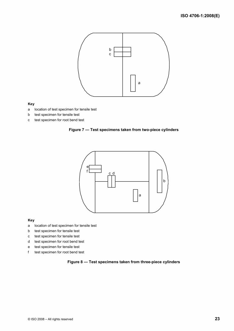
a) for cylinders containing only circumferential welds (two-piece cylinders), on test specimens taken from the locations shown in Figure 7 the following tests shall be carried out:
1) one tensile test (in accordance with the requirements of ISO 6892), parent metal parallel to the circumferential seam or if it is not possible, in the longitudinal direction, or the centre of one dished end;
2) one tensile test (in accordance with the requirements of ISO 4136), perpendicular to the circumferential weld;
3) one root bend test (in accordance with the requirements of ISO 7438), of the circumferential weld;
ISO 4706-1:2008(E)
© ISO 2008 – All rights reserved 17
b) for cylinders with longitudinal and circumferential welds (three piece cylinders), on test specimens taken from the locations shown in Figure 8 the following tests shall be carried out:
1) one tensile test (in accordance with the requirements of ISO 6892), parent metal parallel to the circumferential seam or if it is not possible, in the longitudinal direction, or the centre of one dished end;
2) one tensile test (in accordance with the requirements of ISO 6892), parent metal from one dished end, b);
3) one tensile test (in accordance with the requirements of ISO 4136), of longitudinal weld, c);
4) one root bend test (in accordance with the requirements of ISO 7438), of the longitudinal weld, d);
5) one tensile test (in accordance with the requirements of ISO 4136), of circumferential weld, e);
6) one root bend test (in accordance with the requirements of ISO 7438), of the circumferential weld, f).
9.1.2.2 Tensile test
9.1.2.2.1 Tensile test on parent metal
9.1.2.2.1.1 Tensile tests shall be carried out in accordance with the requirements of ISO 6892.
The two faces of the test specimen representing the inside and outside walls of the cylinder respectively shall not be machined.
9.1.2.2.1.2 The values obtained for yield strength and tensile strength shall not be less than those guaranteed by the cylinder manufacturer. Elongation (%) shall not be less than that specified in Table 1.
NOTE a u 3 for a 20 mm × 80 mm specimen.
a > 3, proportional Lo = 5.65 oS specimen
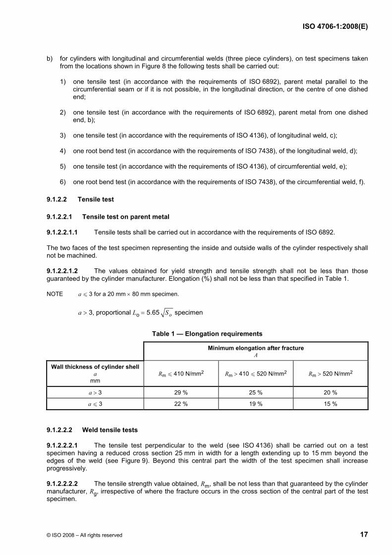
Table 1 — Elongation requirements
Minimum elongation after fracture A
Wall thickness of cylinder shell a
mm Rm u 410 N/mm2 Rm > 410 u 520 N/mm2 Rm > 520 N/mm2
a > 3 29 % 25 % 20 %
a u 3 22 % 19 % 15 %
9.1.2.2.2 Weld tensile tests
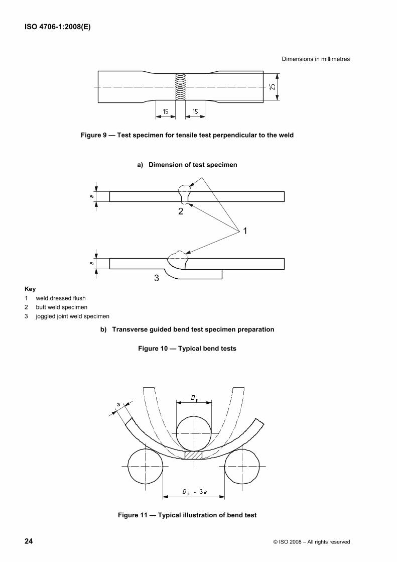
9.1.2.2.2.1 The tensile test perpendicular to the weld (see ISO 4136) shall be carried out on a test specimen having a reduced cross section 25 mm in width for a length extending up to 15 mm beyond the edges of the weld (see Figure 9). Beyond this central part the width of the test specimen shall increase progressively.
9.1.2.2.2.2 The tensile strength value obtained, Rm, shall be not less than that guaranteed by the cylinder manufacturer, Rg, irrespective of where the fracture occurs in the cross section of the central part of the test specimen.
ISO 4706-1:2008(E)
18 © ISO 2008 – All rights reserved
9.1.2.3 Bend test
9.1.2.3.1 The procedure for carrying out a bend test is given in ISO 7438. The bend test specimen shall be 25 mm in width. The mandrel shall be placed in the centre of the weld while the test is being performed and remain in that position until the conclusion of the test (see Figure 10).
9.1.2.3.2 Cracks shall not appear in the test specimen when it is bent around a mandrel through 180° (see Figure 11).
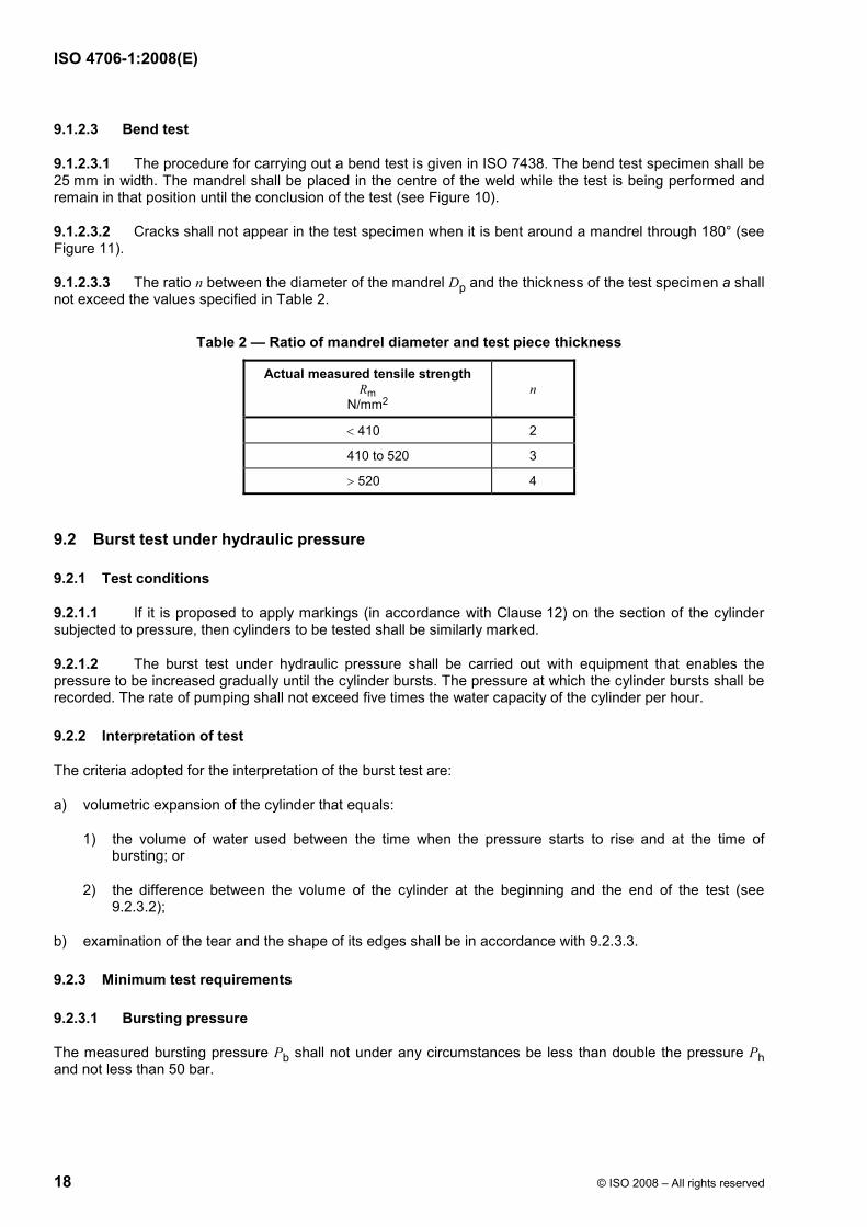
9.1.2.3.3 The ratio n between the diameter of the mandrel Dp and the thickness of the test specimen a shall not exceed the values specified in Table 2.
Table 2 — Ratio of mandrel diameter and test piece thickness
Actual measured tensile strength Rm
N/mm2 n
< 410 2
410 to 520 3
> 520 4
9.2 Burst test under hydraulic pressure
9.2.1 Test conditions
9.2.1.1 If it is proposed to apply markings (in accordance with Clause 12) on the section of the cylinder subjected to pressure, then cylinders to be tested shall be similarly marked.
9.2.1.2 The burst test under hydraulic pressure shall be carried out with equipment that enables the pressure to be increased gradually until the cylinder bursts. The pressure at which the cylinder bursts shall be recorded. The rate of pumping shall not exceed five times the water capacity of the cylinder per hour.
9.2.2 Interpretation of test
The criteria adopted for the interpretation of the burst test are:
a) volumetric expansion of the cylinder that equals:
1) the volume of water used between the time when the pressure starts to rise and at the time of bursting; or
2) the difference between the volume of the cylinder at the beginning and the end of the test (see 9.2.3.2);
b) examination of the tear and the shape of its edges shall be in accordance with 9.2.3.3.
9.2.3 Minimum test requirements
9.2.3.1 Bursting pressure
The measured bursting pressure Pb shall not under any circumstances be less than double the pressure Ph and not less than 50 bar.
ISO 4706-1:2008(E)
© ISO 2008 – All rights reserved 19
9.2.3.2 Volumetric expansion
The ratio of volumetric expansion of the cylinder at burst to its initial volume shall be greater than or equal to:
a) where the minimum value of Rg is u 410 N/mm2:
1) 20 % if the length of the cylinder is greater than its diameter;
2) 14 % if the length of the cylinder is equal to or less than its diameter;
b) where the minimum value of Rg is > 410 N/mm2:
1) 15 % if the length of the cylinder is greater than its diameter;
2) 10 % if the length of the cylinder is equal to or less than its diameter.
9.2.3.3 Type of fracture
a) the burst test shall not cause any fragmentation of the cylinder;
b) the main fracture shall not show any brittleness (i.e. the edges of the fracture shall not be radial but shall be at an angle to a diametrical plane and display a reduction of area throughout their thickness);
c) the fracture shall not reveal a visible defect in the metal;
d) the fracture shall not initiate in a weld;
e) the fracture shall not initiate in a marking area (see 12.4);
f) the fracture shall not initiate from a weld securing, a welded footring or welded shroud.
9.3 Pressure test
9.3.1 The pressurization medium may be liquid or gas provided safety precautions have been taken.
9.3.2 The pressure indicating device(s) shall be certified to an accuracy of 0,5 % at cylinder test pressure (Ph).
9.3.3 The manufacturer shall employ manufacturing practices and techniques that will demonstrate that the cylinders do not leak when subjected to the minimum test pressure (Ptmin).
9.3.4 The minimum test pressure Ptmin to be applied shall be as specified in 6.1.3.
For butane only, the stress within the wall of the cylinder shall not exceed 90 % of the minimum yield strength of the material Re during the test.
9.3.5 The pressure in the cylinder shall increase gradually until the test pressure is reached.
9.3.6 The cylinder shall remain at the test pressure for a period of time, at least 10 s for testing with gaseous media and 30 s for liquid media, that will make it possible to establish that no leak in the cylinder or welds can be observed.
9.3.7 After the test the cylinder shall show no signs of permanent deformation.
9.3.8 Where the manufacturer employs a gas as the pressurization medium for the pressure test, then no leakage test shall be required. Otherwise, each cylinder shall be subjected to a leak test using a gaseous media at the marked service pressure of the cylinder.
ISO 4706-1:2008(E)
20 © ISO 2008 – All rights reserved
9.4 Radiographic and macro examination
9.4.1 Radiographic examination
9.4.1.1 General
The radiographic examination may be replaced by radioscopy or another suitable non-destructive testing (NDT) method if the applied method is carried out in accordance with a process that provides the same level of quality of examination as radiographic examination. Radiographic examination shall conform to the techniques specified in 9.4.1.2 and 9.4.1.3.
9.4.1.2 Welds shall be radiographed in accordance with ISO 17636, Class B.
9.4.1.3 Cylinders shall not have any of the following imperfections as specified in ISO 5817:
a) cracks, inadequate welds, lack of penetration or lack of fusion of the weld;
b) elongated inclusions or any group of rounded inclusions in a row where the length represented over a weld length of 12a is greater than 6 mm;
c) any gas pores measuring more than (a/3) mm;
d) any gas pores measuring more than (a/4) mm, which is 25 mm or less from any other gas pore;
e) gas pores over any 100 mm length, where the total area, in mm2, of all the figures is greater than 2a.
9.4.2 Macro examination
The macro examination, carried out in accordance with ISO 17639, of a full transverse section of the welds shall show complete fusion and complete penetration as specified in 8.2.9 c). In case of doubt, a microscopic examination shall be made of the suspect area.
9.4.3 Examination of flange welding
For the examination of the flange welding, radiographic or macro examination shall be carried out at time of type approval as indicated in 11.1 or at any time the welding parameters change.
9.4.4 Examination of welding of non pressure containing attachments
For the examination of welding of non-pressure containing attachments, radiographic or macro examinations shall be carried out at the time of type approval in accordance with 10.1 or at any time the welding parameters change.
9.4.5 Unacceptable imperfections at radiographic or macro examination
Should any of the radiographic or macro examinations show any unacceptable imperfections, production shall be stopped and every cylinder welded since the preceding acceptable radiographic or macro examination shall be set aside until it is demonstrated that these cylinders are satisfactory either by radiographic or macro examination or other appropriate means. Production shall not be restarted until the cause of the defect has been established and rectified, and the starting up test procedure as specified in 10.1.3 has been repeated.
9.5 Visual examination of the surface of the weld
9.5.1 Examination of the completed weld in accordance with the requirements of ISO 17637, shall be carried out when the weld has been completed. The welded surface examined shall be well illuminated, and shall be free from grease, dust, scale residue or protective coating of any kind.
9.5.2 The weld shall conform to the requirements of 8.4.
ISO 4706-1:2008(E)
© ISO 2008 – All rights reserved 21
9.6 Fatigue testing/cycle testing
9.6.1 For the purpose of this test, three cylinders which are guaranteed by the manufacturer to be representative of the minimum end(s) thickness set by the design and which include all marking (in accordance with Clause 12) shall be filled with a non-corrosive liquid and subjected to successive reversals of hydraulic pressure.
9.6.2 The test shall be carried out at an upper cyclic pressure, either:
a) equal to two thirds of the test pressure, in which case the cylinder shall be subjected to 80 000 cycles without failure; or
b) equal to the test pressure, in which case the cylinder shall be subjected to 12 000 cycles without failure.
The value of the lower cyclic pressure shall not exceed 10 % of the upper cyclic pressure. The frequency of reversals of pressure shall not exceed 0,25 Hz (15 cycles/min). The temperature measured on the outside surface of the cylinder shall not exceed 50 °C during the test.
9.6.3 After testing in accordance with 9.6.2, the cylinder shall be burst tested. When burst tested the cylinder shall conform to the requirements of 9.2.3.1.
10 Acceptance criteria
10.1 General
10.1.1 All acceptance testing as required by this clause shall be carried out on cylinder shells, prior to surface treatment.
10.1.2 All cylinders shall be subject to a pressure test as specified in 9.3 and visual examination of the surface of the welds as specified in 9.5.
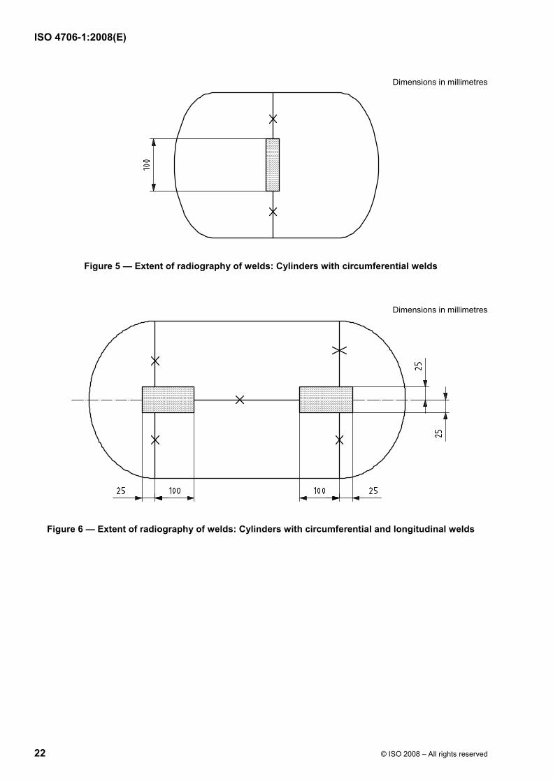
10.1.3 Radiographic examination and macro examination shall be carried out as specified in 9.4. Radiography shall be carried out on the longitudinal weld (see Figures 5 and 6) of the first production cylinder or of an inspection lot after a change in type or size of cylinder or the welding procedure (including machine setting), or after a break in production exceeding 4 h.
In the case of cylinders with outside diameter less than 250 mm, radiography of joggle joints circumferential welds may be replaced by two macro examinations (see 9.4.2) one of which shall be at the plane of the stop/start area and the other on the opposite side of the cylinder.
In addition, for cylinders with longitudinal welds, one cylinder out of every 250 production cylinders shall have the junction of the longitudinal and circumferential welds radiographed as indicated in Figure 6.
Where more than one welding machine is used for production, the above procedures shall apply to each machine.
10.1.4 Mechanical testing as specified in 9.1 and burst testing as specified in 9.2 shall be carried out on samples as specified in 10.2.
10.1.5 The cylinder used for mechanical testing shall be profiled for determination of the minimum wall thickness. The minimum wall thickness noted in the cylinder sidewall shall be W a and the minimum wall thickness in the cylinder heads shall be W b.
ISO 4706-1:2008(E)
22 © ISO 2008 – All rights reserved
Dimensions in millimetres
Figure 5 — Extent of radiography of welds: Cylinders with circumferential welds
Dimensions in millimetres
Figure 6 — Extent of radiography of welds: Cylinders with circumferential and longitudinal welds
ISO 4706-1:2008(E)
© ISO 2008 – All rights reserved 23
Key a location of test specimen for tensile test b test specimen for tensile test c test specimen for root bend test
Figure 7 — Test specimens taken from two-piece cylinders
Key a location of test specimen for tensile test b test specimen for tensile test c test specimen for tensile test d test specimen for root bend test e test specimen for tensile test f test specimen for root bend test
Figure 8 — Test specimens taken from three-piece cylinders
ISO 4706-1:2008(E)
24 © ISO 2008 – All rights reserved
Dimensions in millimetres
Figure 9 — Test specimen for tensile test perpendicular to the weld
a) Dimension of test specimen
Key 1 weld dressed flush 2 butt weld specimen 3 joggled joint weld specimen
b) Transverse guided bend test specimen preparation
Figure 10 — Typical bend tests
Figure 11 — Typical illustration of bend test
ISO 4706-1:2008(E)
© ISO 2008 – All rights reserved 25
10.2 Batch testing
10.2.1 Inspection lots
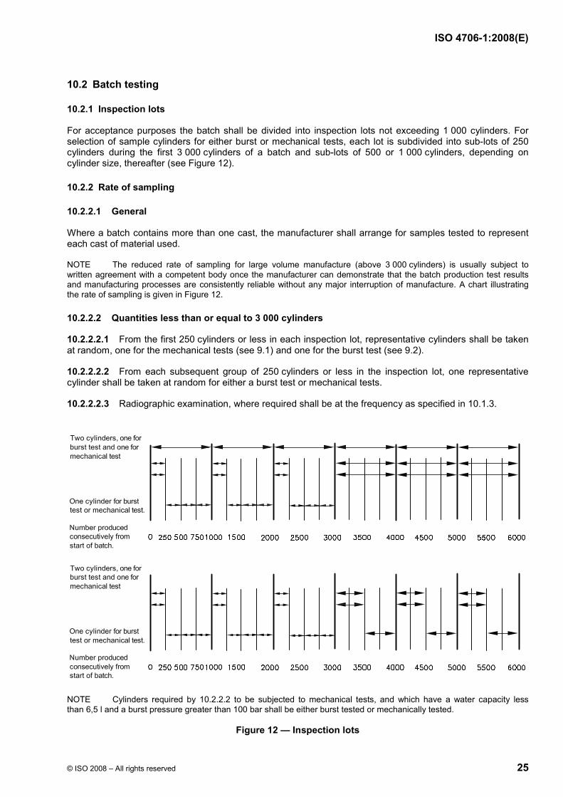
For acceptance purposes the batch shall be divided into inspection lots not exceeding 1 000 cylinders. For selection of sample cylinders for either burst or mechanical tests, each lot is subdivided into sub-lots of 250 cylinders during the first 3 000 cylinders of a batch and sub-lots of 500 or 1 000 cylinders, depending on cylinder size, thereafter (see Figure 12).
10.2.2 Rate of sampling
10.2.2.1 General
Where a batch contains more than one cast, the manufacturer shall arrange for samples tested to represent each cast of material used.
NOTE The reduced rate of sampling for large volume manufacture (above 3 000 cylinders) is usually subject to written agreement with a competent body once the manufacturer can demonstrate that the batch production test results and manufacturing processes are consistently reliable without any major interruption of manufacture. A chart illustrating the rate of sampling is given in Figure 12.
10.2.2.2 Quantities less than or equal to 3 000 cylinders
10.2.2.2.1 From the first 250 cylinders or less in each inspection lot, representative cylinders shall be taken at random, one for the mechanical tests (see 9.1) and one for the burst test (see 9.2).
10.2.2.2.2 From each subsequent group of 250 cylinders or less in the inspection lot, one representative cylinder shall be taken at random for either a burst test or mechanical tests.
10.2.2.2.3 Radiographic examination, where required shall be at the frequency as specified in 10.1.3.
NOTE Cylinders required by 10.2.2.2 to be subjected to mechanical tests, and which have a water capacity less than 6,5 l and a burst pressure greater than 100 bar shall be either burst tested or mechanically tested.
Figure 12 — Inspection lots
ISO 4706-1:2008(E)
26 © ISO 2008 – All rights reserved
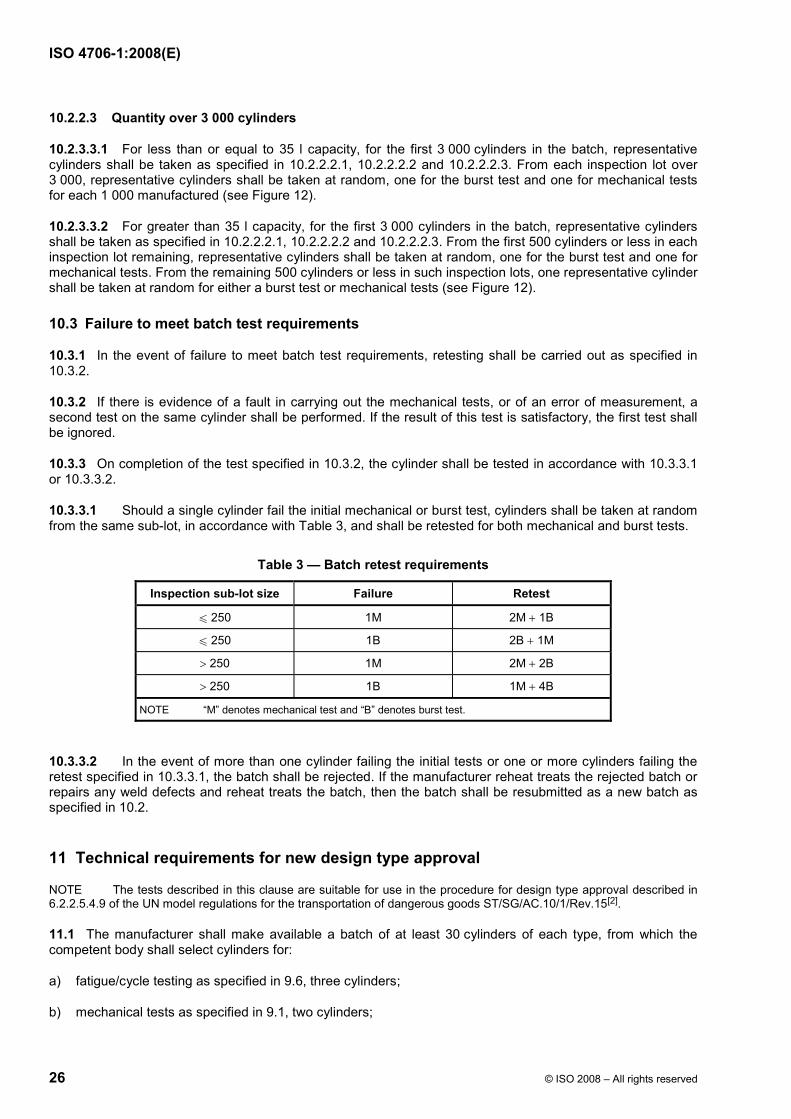
10.2.2.3 Quantity over 3 000 cylinders
10.2.3.3.1 For less than or equal to 35 l capacity, for the first 3 000 cylinders in the batch, representative cylinders shall be taken as specified in 10.2.2.2.1, 10.2.2.2.2 and 10.2.2.2.3. From each inspection lot over 3 000, representative cylinders shall be taken at random, one for the burst test and one for mechanical tests for each 1 000 manufactured (see Figure 12).
10.2.3.3.2 For greater than 35 l capacity, for the first 3 000 cylinders in the batch, representative cylinders shall be taken as specified in 10.2.2.2.1, 10.2.2.2.2 and 10.2.2.2.3. From the first 500 cylinders or less in each inspection lot remaining, representative cylinders shall be taken at random, one for the burst test and one for mechanical tests. From the remaining 500 cylinders or less in such inspection lots, one representative cylinder shall be taken at random for either a burst test or mechanical tests (see Figure 12).
10.3 Failure to meet batch test requirements
10.3.1 In the event of failure to meet batch test requirements, retesting shall be carried out as specified in 10.3.2.
10.3.2 If there is evidence of a fault in carrying out the mechanical tests, or of an error of measurement, a second test on the same cylinder shall be performed. If the result of this test is satisfactory, the first test shall be ignored.
10.3.3 On completion of the test specified in 10.3.2, the cylinder shall be tested in accordance with 10.3.3.1 or 10.3.3.2.
10.3.3.1 Should a single cylinder fail the initial mechanical or burst test, cylinders shall be taken at random from the same sub-lot, in accordance with Table 3, and shall be retested for both mechanical and burst tests.
Table 3 — Batch retest requirements
Inspection sub-lot size Failure Retest
u 250 1M 2M + 1B
u 250 1B 2B + 1M
> 250 1M 2M + 2B
> 250 1B 1M + 4B
NOTE “M” denotes mechanical test and “B” denotes burst test.
10.3.3.2 In the event of more than one cylinder failing the initial tests or one or more cylinders failing the retest specified in 10.3.3.1, the batch shall be rejected. If the manufacturer reheat treats the rejected batch or repairs any weld defects and reheat treats the batch, then the batch shall be resubmitted as a new batch as specified in 10.2.
11 Technical requirements for new design type approval
NOTE The tests described in this clause are suitable for use in the procedure for design type approval described in 6.2.2.5.4.9 of the UN model regulations for the transportation of dangerous goods ST/SG/AC.10/1/Rev.15[2].
11.1 The manufacturer shall make available a batch of at least 30 cylinders of each type, from which the competent body shall select cylinders for:
a) fatigue/cycle testing as specified in 9.6, three cylinders;
b) mechanical tests as specified in 9.1, two cylinders;
ISO 4706-1:2008(E)
© ISO 2008 – All rights reserved 27
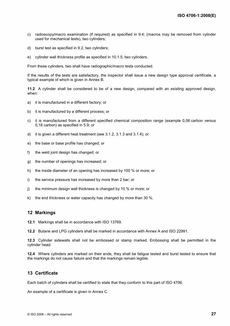
c) radioscopy/macro examination (if required) as specified in 9.4; (macros may be removed from cylinder used for mechanical tests), two cylinders;
d) burst test as specified in 9.2, two cylinders;
e) cylinder wall thickness profile as specified in 10.1.5, two cylinders.
From these cylinders, two shall have radiographic/macro tests conducted.
If the results of the tests are satisfactory, the inspector shall issue a new design type approval certificate, a typical example of which is given in Annex B.
11.2 A cylinder shall be considered to be of a new design, compared with an existing approved design, when:
a) it is manufactured in a different factory; or
b) it is manufactured by a different process; or
c) it is manufactured from a different specified chemical composition range (example 0,06 carbon versus 0,18 carbon) as specified in 5.9; or
d) it is given a different heat treatment (see 3.1.2, 3.1.3 and 3.1.4); or
e) the base or base profile has changed; or
f) the weld joint design has changed; or
g) the number of openings has increased; or
h) the inside diameter of an opening has increased by 100 % or more; or
i) the service pressure has increased by more than 2 bar; or
j) the minimum design wall thickness is changed by 10 % or more; or
k) the end thickness or water capacity has changed by more than 30 %.
12 Markings
12.1 Markings shall be in accordance with ISO 13769.
12.2 Butane and LPG cylinders shall be marked in accordance with Annex A and ISO 22991.
12.3 Cylinder sidewalls shall not be embossed or stamp marked. Embossing shall be permitted in the cylinder head.
12.4 Where cylinders are marked on their ends, they shall be fatigue tested and burst tested to ensure that the markings do not cause failure and that the markings remain legible.
13 Certificate
Each batch of cylinders shall be certified to state that they conform to this part of ISO 4706.
An example of a certificate is given in Annex C.
ISO 4706-1:2008(E)
28 © ISO 2008 – All rights reserved
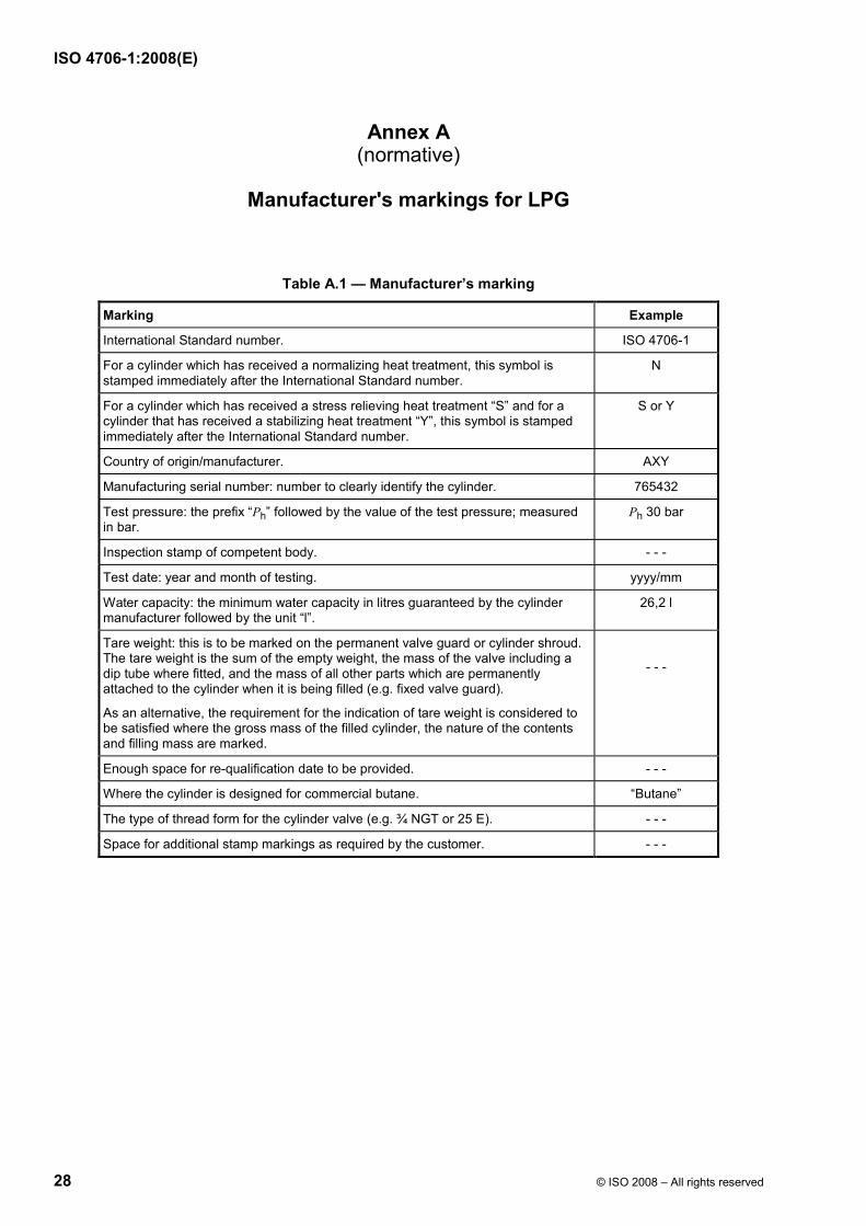
Annex A (normative)
Manufacturer's markings for LPG
Table A.1 — Manufacturer’s marking
Marking Example
International Standard number. ISO 4706-1
For a cylinder which has received a normalizing heat treatment, this symbol is stamped immediately after the International Standard number.
N
For a cylinder which has received a stress relieving heat treatment “S” and for a cylinder that has received a stabilizing heat treatment “Y”, this symbol is stamped immediately after the International Standard number.
S or Y
Country of origin/manufacturer. AXY
Manufacturing serial number: number to clearly identify the cylinder. 765432
Test pressure: the prefix “Ph” followed by the value of the test pressure; measured in bar.
Ph 30 bar
Inspection stamp of competent body. - - -
Test date: year and month of testing. yyyy/mm
Water capacity: the minimum water capacity in litres guaranteed by the cylinder manufacturer followed by the unit “l”.
26,2 l
Tare weight: this is to be marked on the permanent valve guard or cylinder shroud. The tare weight is the sum of the empty weight, the mass of the valve including a dip tube where fitted, and the mass of all other parts which are permanently attached to the cylinder when it is being filled (e.g. fixed valve guard).
As an alternative, the requirement for the indication of tare weight is considered to be satisfied where the gross mass of the filled cylinder, the nature of the contents and filling mass are marked.
- - -
Enough space for re-qualification date to be provided. - - -
Where the cylinder is designed for commercial butane. “Butane”
The type of thread form for the cylinder valve (e.g. ¾ NGT or 25 E). - - -
Space for additional stamp markings as required by the customer. - - -
ISO 4706-1:2008(E)
© ISO 2008 – All rights reserved 29
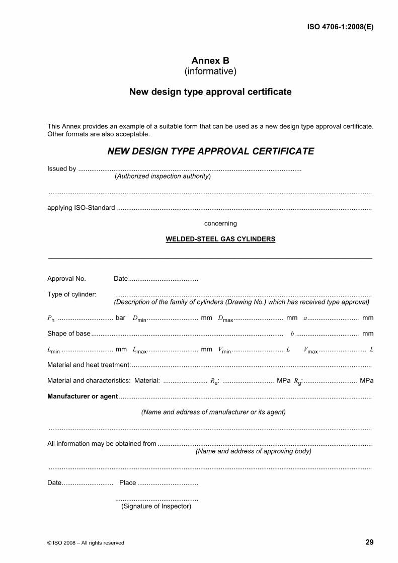
Annex B (informative)
New design type approval certificate
This Annex provides an example of a suitable form that can be used as a new design type approval certificate. Other formats are also acceptable.
NEW DESIGN TYPE APPROVAL CERTIFICATE
Issued by ......................................................................................................................... (Authorized inspection authority)
...............................................................................................................................................................................
applying ISO-Standard ..........................................................................................................................................
concerning
WELDED-STEEL GAS CYLINDERS
________________________________________________________________________________________________
Approval No. Date......................................
Type of cylinder: ........................................................................................................................................... (Description of the family of cylinders (Drawing No.) which has received type approval)
Ph .............................. bar Dmin............................ mm Dmax........................... mm a............................ mm
Shape of base........................................................................................................ b .................................. mm
Lmin ............................ mm Lmax............................ mm Vmin............................ L Vmax.......................... L
Material and heat treatment: ..................................................................................................................................
Material and characteristics: Material: ........................ Re: ............................ MPa Rg:............................. MPa
Manufacturer or agent .........................................................................................................................................
(Name and address of manufacturer or its agent)
...............................................................................................................................................................................
All information may be obtained from .................................................................................................................... (Name and address of approving body)
...............................................................................................................................................................................
Date............................ Place .................................
............................................. (Signature of Inspector)
ISO 4706-1:2008(E)
30 © ISO 2008 – All rights reserved
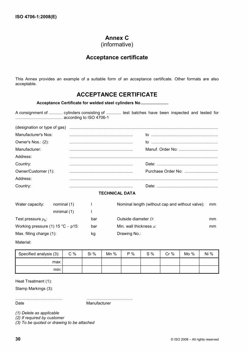
Annex C (informative)
Acceptance certificate
This Annex provides an example of a suitable form of an acceptance certificate. Other formats are also acceptable.
ACCEPTANCE CERTIFICATE Acceptance Certificate for welded steel cylinders No........................
A consignment of ............ cylinders consisting of ............. test batches have been inspected and tested for ......................................... according to ISO 4706-1
(designation or type of gas) .................................................................................................................................
Manufacturer's Nos: ....................................................... to ..........................................................
Owner's Nos.: (2): ....................................................... to ..........................................................
Manufacturer: ....................................................... Manuf. Order No: ..................................
Address: .................................................................................................................................
Country: ....................................................... Date: .....................................................
Owner/Customer (1): ....................................................... Purchase Order No: .............................
Address: .................................................................................................................................
Country: ....................................................... Date: .....................................................
TECHNICAL DATA
Water capacity: nominal (1) l Nominal length (without cap and without valve): mm
minimal (1) l
Test pressure ph: bar Outside diameter D: mm
Working pressure (1) 15 °C − p15: bar Min. wall thickness a: mm
Max. filling charge (1): kg Drawing No.:
Material:
Specified analysis (3): C % Si % Mn % P % S % Cr % Mo % Ni %
max:
min:
Heat Treatment (1):
Stamp Markings (3):
......................................... ........................................ Date Manufacturer
(1) Delete as applicable (2) If required by customer (3) To be quoted or drawing to be attached
ISO 4706-1:2008(E)
© ISO 2008 – All rights reserved 31
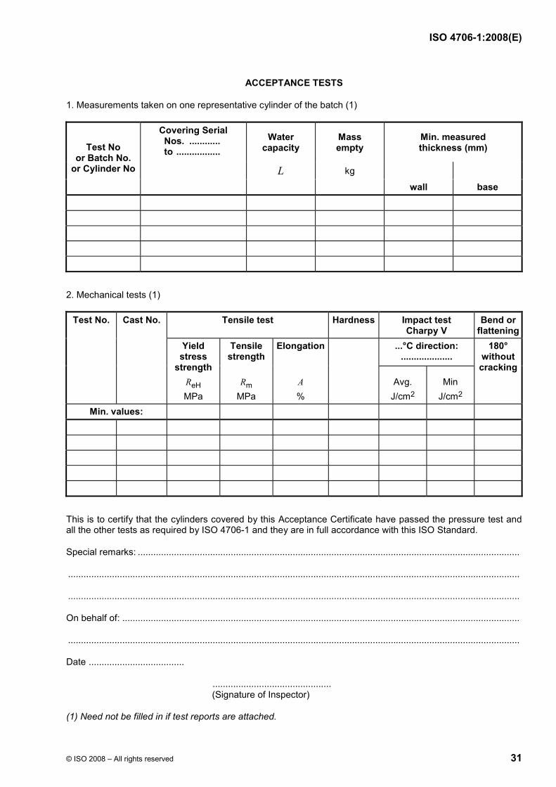
ACCEPTANCE TESTS
1. Measurements taken on one representative cylinder of the batch (1)
Water capacity
Mass empty
Min. measured thickness (mm)
L kg
Test No or Batch No.
or Cylinder No
Covering Serial Nos. ............ to .................
wall base
2. Mechanical tests (1)
Tensile test Hardness Impact test Charpy V
Bend or flattening
...°C direction: ....................
Test No. Cast No.
Yield stress
strength ReH MPa
Tensile strength
Rm
MPa
Elongation
A %
Avg. J/cm2
Min J/cm2
180° without cracking
Min. values:
This is to certify that the cylinders covered by this Acceptance Certificate have passed the pressure test and all the other tests as required by ISO 4706-1 and they are in full accordance with this ISO Standard.
Special remarks: ....................................................................................................................................................
...............................................................................................................................................................................
...............................................................................................................................................................................
On behalf of: ..........................................................................................................................................................
...............................................................................................................................................................................
Date .....................................
.............................................. (Signature of Inspector)
(1) Need not be filled in if test reports are attached.
ISO 4706-1:2008(E)
32 © ISO 2008 – All rights reserved
Bibliography
[1] ISO/TR 14600, Gas cylinders — International quality conformance system — Basic rules
[2] ST/SG/AC.10/1/Rev.15, Recommendations on the Transport of Dangerous Goods, Model Regulations, Fifteenth revised edition, July 2007

ISO 4706-1:2008(E)
ICS 23.020.30 Price based on 32 pages
© ISO 2008 – All rights reserved