Embed Size (px)
Citation preview
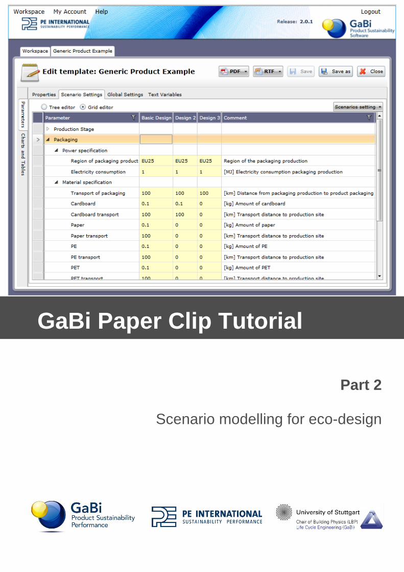
Part 2
Scenario modelling for eco-design
GaBi Paper Clip Tutorial

March 2013
PE INTERNATIONAL Hauptstraße 111-115 70771 Leinfelden-Echterdingen Germany
Phone +49 [0] 711 3418170 Fax +49 [0] 711 34181725
E-Mail [email protected]
Internet www.pe-international.com
i
Table of Contents Purpose of this Handbook .................................................................................... 11 What is Scenario Modeling? ................................................................ 21.1 Why do organisations do scenario modelling? ................................................. 21.2 What is GaBi Envision? ................................................................................... 21.3 The interactive-report in GaBi .......................................................................... 31.4 The interactive report look in GaBi Envision .................................................... 3
2 Parameters ............................................................................................ 52.1 Parameters as the basis of scenario modelling ................................................ 52.2 Process parameters ......................................................................................... 52.3 Creating a process parameter ......................................................................... 72.4 Adding comments ............................................................................................ 82.5 Entering a value ............................................................................................... 82.6 Creating a formula ........................................................................................... 92.7 Linking parameters to flows ........................................................................... 10
3 Building the scenario interface ......................................................... 133.1 The parameter explorer ................................................................................. 133.2 Getting to know the parameter explorer interface .......................................... 173.3 The scenarios tab .......................................................................................... 173.4 The scenario and subset creator .................................................................... 173.5 The structure & settings builder ..................................................................... 17
4 Creating scenario groups and scenarios ......................................... 194.1 Creating a scenario group .............................................................................. 194.2 Adding scenarios ........................................................................................... 19
5 Establishing the i-report start settings ............................................. 215.1 Selecting an object ........................................................................................ 215.2 Linking to a parameter ................................................................................... 215.3 Renaming the alias ........................................................................................ 225.4 Entering scenario values ............................................................................... 22
6 Creating collapsible sections ............................................................ 246.1 Changing title levels ....................................................................................... 246.2 Organising rows ............................................................................................. 25
7 Getting the Model done ...................................................................... 268 Creating drop-down menus ............................................................... 278.1 Creating a subset .......................................................................................... 278.2 Adding subset scenarios ................................................................................ 288.3 Selecting an object ........................................................................................ 298.4 Select a parameter ........................................................................................ 298.5 Predefining values ......................................................................................... 30
ii
8.6 Adding the subset to the scenario ininterface ................................................. 30
9 Creating sliders and setting min and max values ........................... 339.1 Setting min. and max. values ......................................................................... 339.2 Creating the slider ......................................................................................... 33
10 Activating a scenario, viewing the plan and the LCIA preview ...... 3510.1 Activating a scenario ...................................................................................... 3510.2 Viewing changes to the plan .......................................................................... 3510.3 Using the LCIA preview ................................................................................. 36
11 Creating an i-report with an existing template ................................. 3711.1 How can I create an i-report with an existing template: .................................. 3711.2 Opening a template ....................................................................................... 37
12 Building the i-report - Inserting a diagram ....................................... 3812.1 Inserting a diagram ........................................................................................ 3912.2 Runtime mode ............................................................................................... 4212.3 Editing a diagram ........................................................................................... 42
13 Building the i-report - Inserting a table ............................................. 4713.1 Inserting a table ............................................................................................. 4813.2 Creating a colour comparison ........................................................................ 51
14 Building the i-report – Structure, appearance and editing .............. 5414.1 Introduction .................................................................................................... 5414.2 Inserting structure elements ........................................................................... 5414.3 Adding text .................................................................................................... 5514.4 Text editing functions ..................................................................................... 5614.5 Creating a text variable .................................................................................. 5614.6 Inserting text variables into the report ............................................................ 5614.7 Inserting a plan .............................................................................................. 5814.8 Inserting an image ......................................................................................... 6114.9 Inserting hyperlinks ........................................................................................ 6214.10 Inserting an input field .................................................................................... 6314.11 Add the date .................................................................................................. 63
15 Saving a report ................................................................................... 6415.1 Saving and exporting an i-report: ................................................................... 6415.2 Send to RTF .................................................................................................. 6415.3 Send to PDF .................................................................................................. 6515.4 Saving a template .......................................................................................... 65
16 Exporting an i-report .......................................................................... 6716.1 Exporting a GaBi model file ........................................................................... 6816.2 Selecting what to export ................................................................................ 6816.3 Linking in the i-report template to the model file ............................................. 70
iii
17 What next? .......................................................................................... 7217.1 Using a gbmx in GaBi Envision ...................................................................... 72
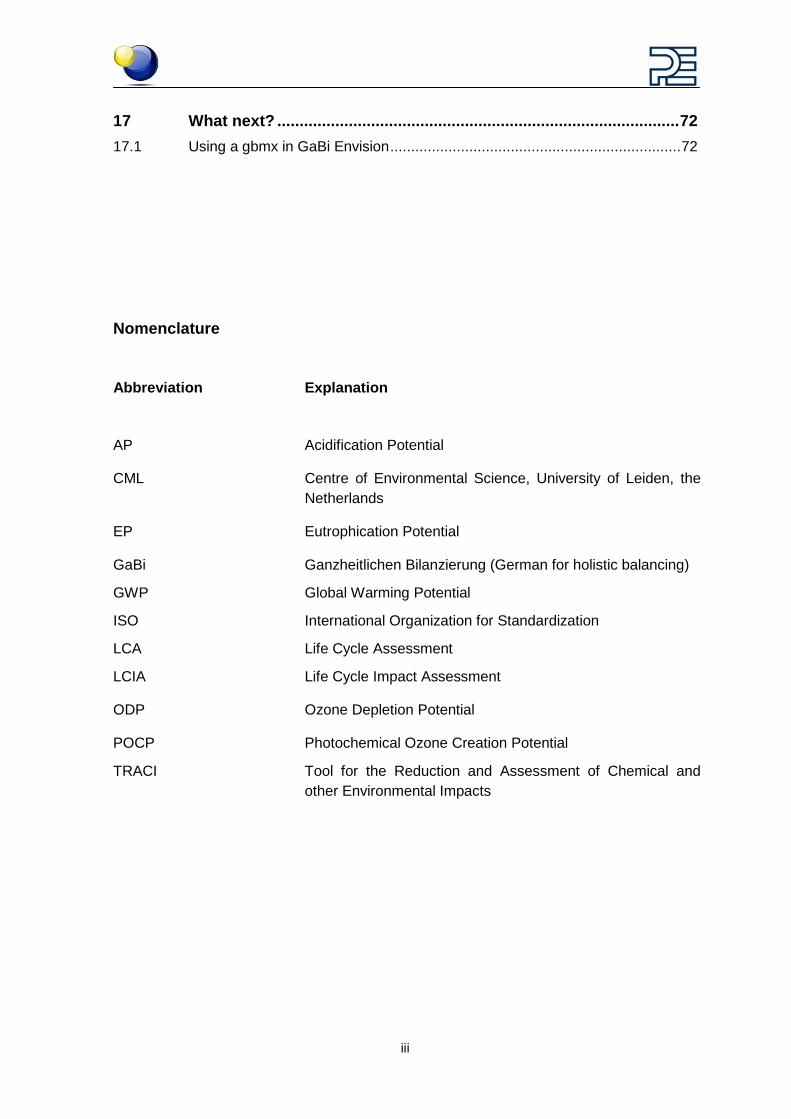
Nomenclature
Abbreviation Explanation
AP Acidification Potential
CML Centre of Environmental Science, University of Leiden, the Netherlands
EP Eutrophication Potential
GaBi Ganzheitlichen Bilanzierung (German for holistic balancing)
GWP Global Warming Potential
ISO International Organization for Standardization
LCA Life Cycle Assessment
LCIA Life Cycle Impact Assessment
ODP Ozone Depletion Potential
POCP Photochemical Ozone Creation Potential
TRACI Tool for the Reduction and Assessment of Chemical and other Environmental Impacts
1
Purpose of this Handbook The purpose of this handbook is to support your learning about Life Cycle Assessment (LCA).
We understand that learning new concepts can be challenging. And everyone has different ways of learning. Some people react best to visual learning, some aural. Some need to draw relationship charts. Some need to read and re-read and some are lucky enough just to absorb everything.
Through the GaBi Learning Centre we’re providing ways of learning that appeal to most of you.
This handbook is intended to support the video tutorials found in the GaBi Learning Centre but can also be used independently from them. After completing the video tutorials, or stepping through the content contained in this handbook, you will be able to:
• do scenario modelling
• work with parameters
• build scenario interfaces
• create scenario groups and scenarios
• establish an i-reports start settings
• create collapsible sections in the scenario interface
• create drop down menus in the scenario interface
• create sliders in the scenario interface
• activate scenarios, view plans and the LCIA preview
• create an i-report with an existing template
• insert a diagram in the report
• insert a table in the report
• create the structure and appearance of the report
• save a report
• export an i-report
Please note that one example (a paper clip) is used throughout the video tutorial series and this handbook.
2
1 What is Scenario Modeling?
1.1 Why do organisations do scenario modelling? Scenario modelling is the most exciting and revealing part of LCA modelling. You may be familiar with building models in GaBi in order to better understand your products’ or proc-esses’ impacts on the environment, society and the economy. But the best thing about building these models is being able to run scenario analysis to see what happens if you change certain aspects of the product system that you modelled.
What happens if I increase the amount of a material used?
What happens if I use a completely different material?
What happens if we transport by air instead of sea?
What happens if I manage to reduce the energy required to run the machinery?
All of these are typical questions that can be addressed using scenario modelling.
Scenario modelling allows non-LCA experts such as sales teams, product designers and engineers, marketers and managers to integrate environmental metrics into decision-making.
Reporting and communication can be enhanced and sped up and the product develop-ment cycle can be supported through detailed environmental, social and economic impact information.
You have already built a lifecycle model for your product using GaBi, but how do you put it in the hands of your design and sourcing teams to start making real changes?
We call the solution GaBi Envision.
1.2 What is GaBi Envision? PE INTERNATIONAL’s scenario modelling solution software is called GaBi Envision.
For the non-LCA professional, GaBi Envision is all that is required to be able to do sce-nario modelling and to create reports.
Scenario modelling is an exciting way to really get a deep understanding of the effects that changes to your product model will have on the environmental, social and economic impacts of your product or process.
Product Lifecycle Models and parameter types are defined in GaBi. Scenario analysis and reporting can then be done by many more users with GaBi Envision.
GaBi allows you to add new materials and control available design options and then pub-lish these to you entire organization so they can make independent decisions while also employing consistent assumptions.
GaBi lets you build LCA models and interactive reports. GaBi Envision then uses these files under an easy user interface to allow scenario modelling and reporting to happen quickly as decisions are made.
3
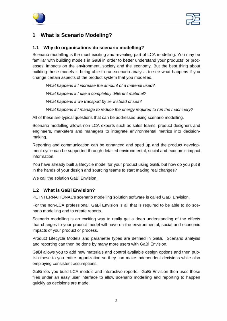
1.3 The interactive-report in GaBi So what does an interactive report look like in GaBi?
Under the i-report tab in the balance window you can work with your interactive report by editing the scenario interface and by creating or modifying the report.
Check out the videos in this tutorial series to learn how to model with parameters, how to build the scenario interface and how to create the report using GaBi.
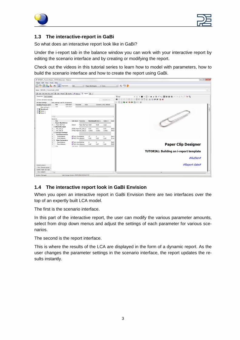
1.4 The interactive report look in GaBi Envision When you open an interactive report in GaBi Envision there are two interfaces over the top of an expertly built LCA model.
The first is the scenario interface.
In this part of the interactive report, the user can modify the various parameter amounts, select from drop down menus and adjust the settings of each parameter for various sce-narios.
The second is the report interface.
This is where the results of the LCA are displayed in the form of a dynamic report. As the user changes the parameter settings in the scenario interface, the report updates the re-sults instantly.
4
5
2 Parameters
2.1 Parameters as the basis of scenario modelling Parameters form the basis of scenario modelling in GaBi.
Parameters are used to vary multiple aspects of a process in order to better understand the impact that changes to the process will have on the results.
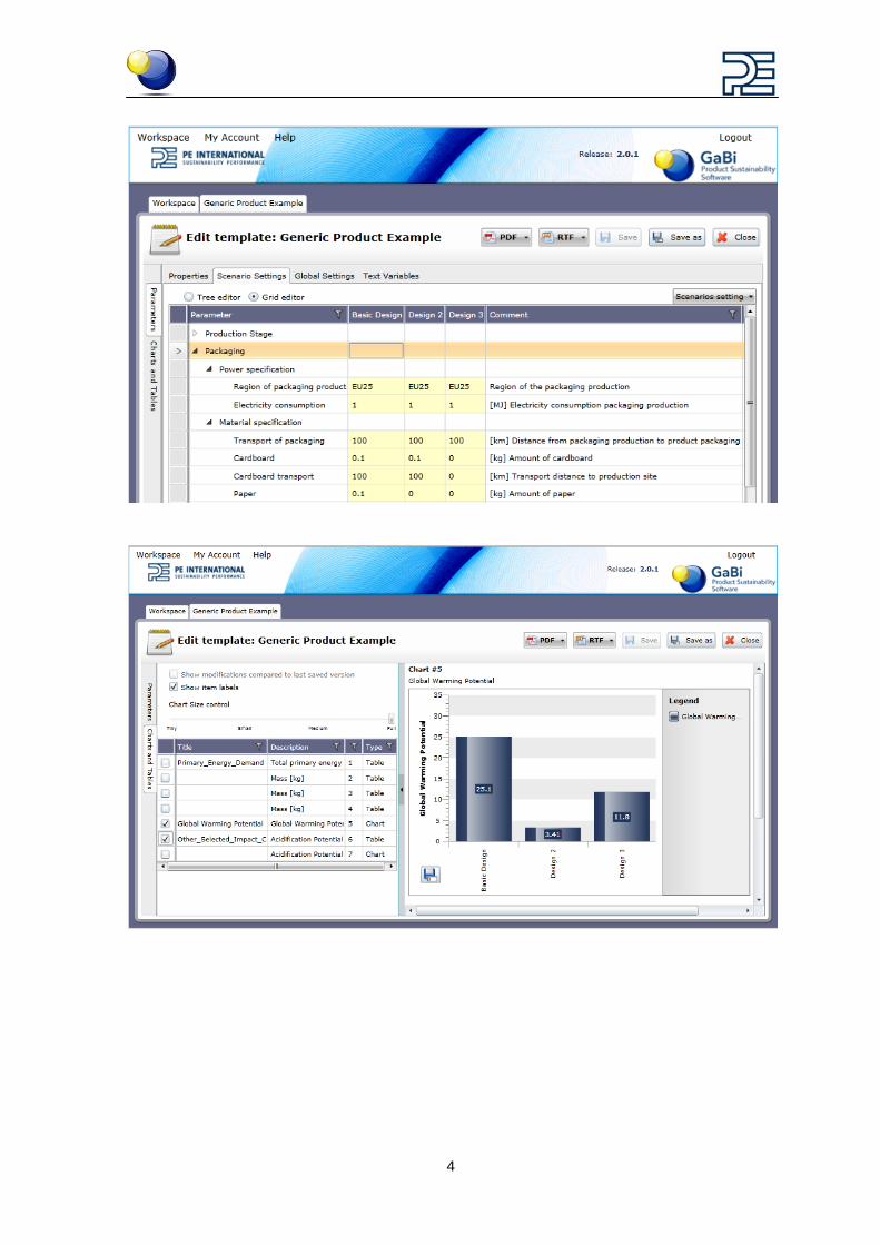
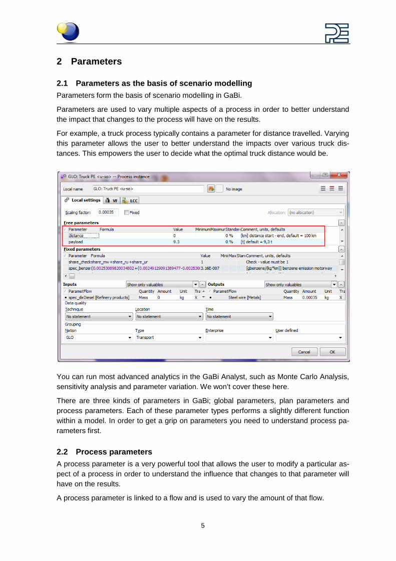
For example, a truck process typically contains a parameter for distance travelled. Varying this parameter allows the user to better understand the impacts over various truck dis-tances. This empowers the user to decide what the optimal truck distance would be.
You can run most advanced analytics in the GaBi Analyst, such as Monte Carlo Analysis, sensitivity analysis and parameter variation. We won’t cover these here.
There are three kinds of parameters in GaBi; global parameters, plan parameters and process parameters. Each of these parameter types performs a slightly different function within a model. In order to get a grip on parameters you need to understand process pa-rameters first.
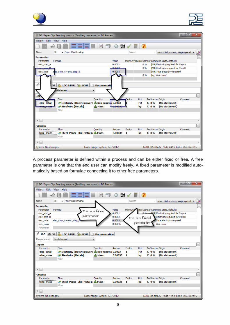
2.2 Process parameters A process parameter is a very powerful tool that allows the user to modify a particular as-pect of a process in order to understand the influence that changes to that parameter will have on the results.
A process parameter is linked to a flow and is used to vary the amount of that flow.
6
A process parameter is defined within a process and can be either fixed or free. A free parameter is one that the end user can modify freely. A fixed parameter is modified auto-matically based on formulae connecting it to other free parameters.
7
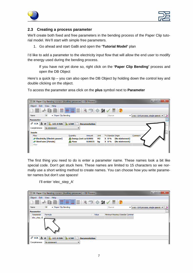
2.3 Creating a process parameter We’ll create both fixed and free parameters in the bending process of the Paper Clip tuto-rial model. We’ll start with simple free parameters.
1. Go ahead and start GaBi and open the ‘Tutorial Model’ plan
I’d like to add a parameter to the electricity input flow that will allow the end user to modify the energy used during the bending process.
If you have not yet done so, right click on the ‘Paper Clip Bending’ process and open the DB Object
Here’s a quick tip – you can also open the DB Object by holding down the control key and double clicking on the object.
To access the parameter area click on the plus symbol next to Parameter
The first thing you need to do is enter a parameter name. These names look a bit like special code. Don’t get stuck here. These names are limited to 15 characters so we nor-mally use a short writing method to create names. You can choose how you write parame-ter names but don’t use spaces!
I’ll enter ‘elec_step_A’
8
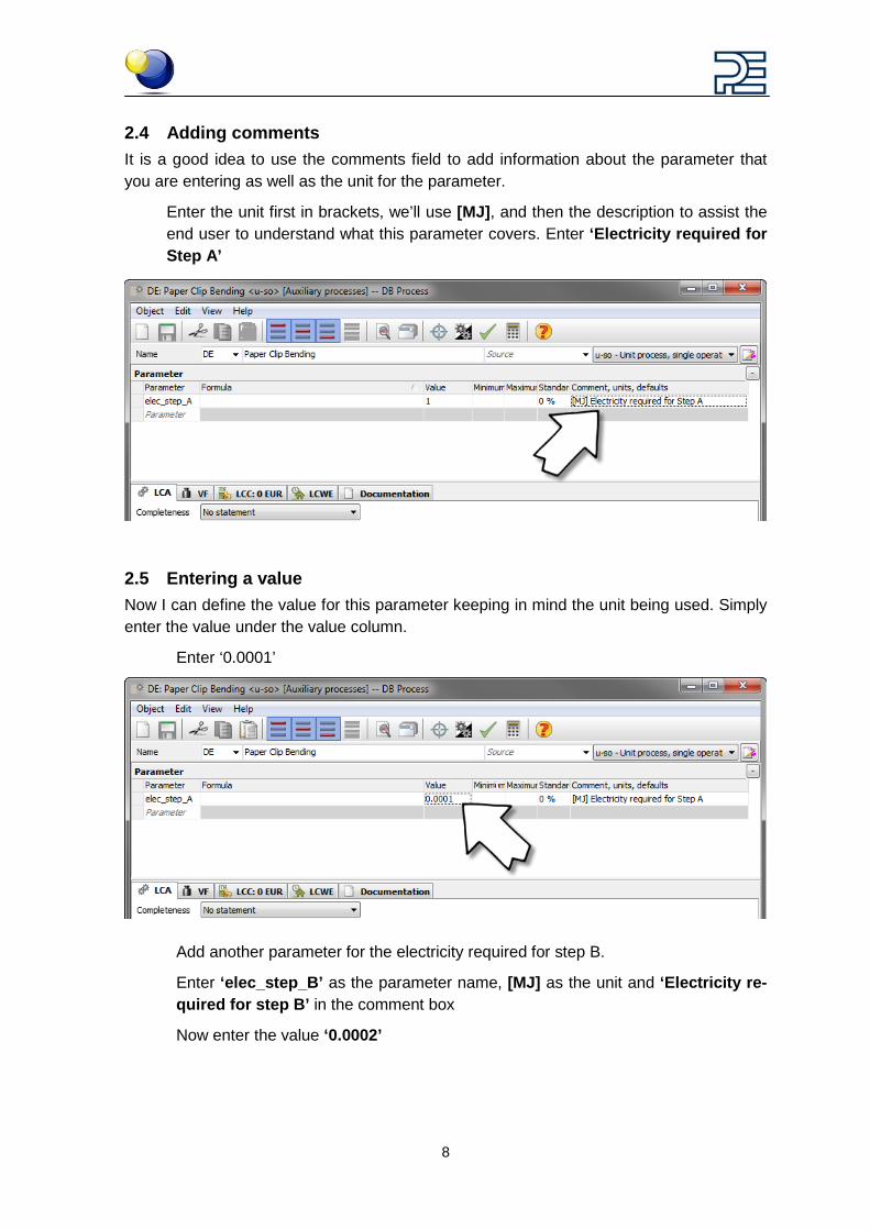
2.4 Adding comments It is a good idea to use the comments field to add information about the parameter that you are entering as well as the unit for the parameter.
Enter the unit first in brackets, we’ll use [MJ], and then the description to assist the end user to understand what this parameter covers. Enter ‘Electricity required for Step A’
2.5 Entering a value Now I can define the value for this parameter keeping in mind the unit being used. Simply enter the value under the value column.
Enter ‘0.0001’
Add another parameter for the electricity required for step B.
Enter ‘elec_step_B’ as the parameter name, [MJ] as the unit and ‘Electricity re-quired for step B’ in the comment box
Now enter the value ‘0.0002’
9
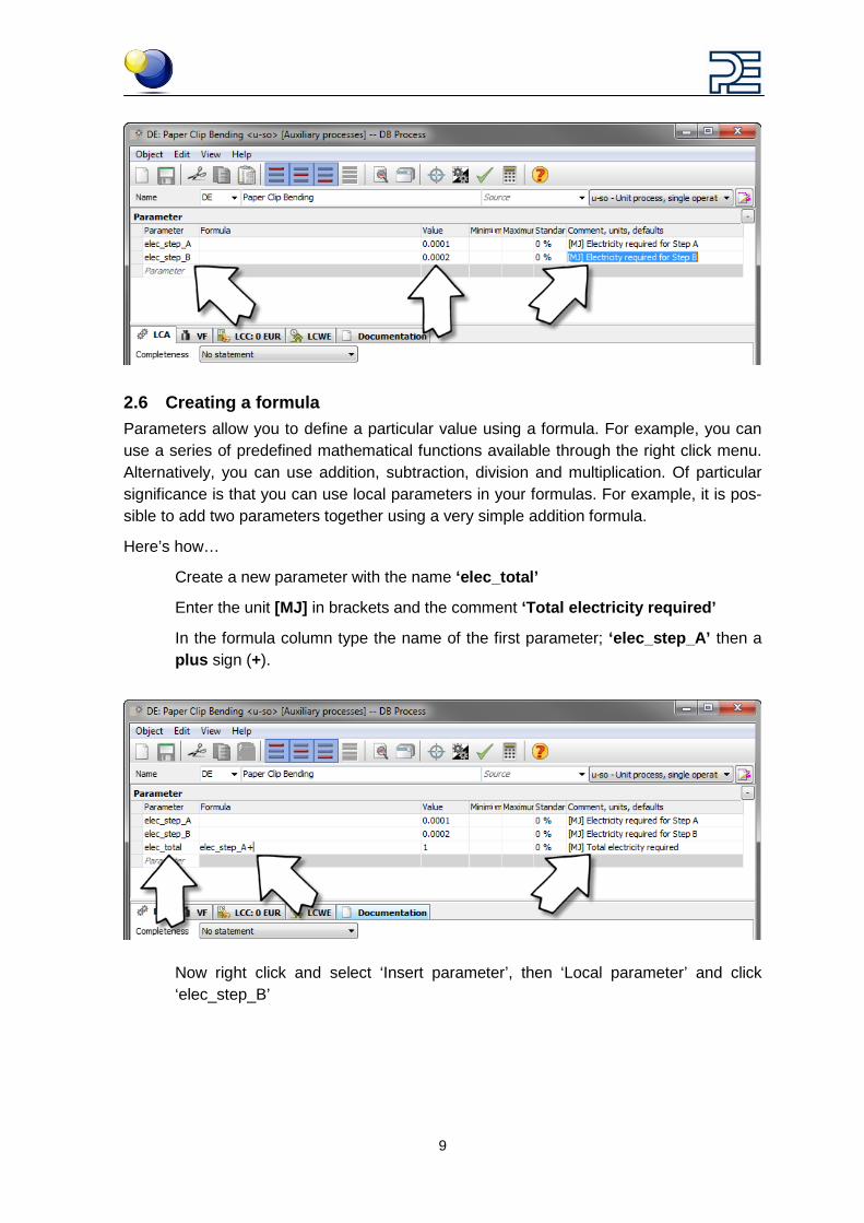
2.6 Creating a formula Parameters allow you to define a particular value using a formula. For example, you can use a series of predefined mathematical functions available through the right click menu. Alternatively, you can use addition, subtraction, division and multiplication. Of particular significance is that you can use local parameters in your formulas. For example, it is pos-sible to add two parameters together using a very simple addition formula.
Here’s how…
Create a new parameter with the name ‘elec_total’
Enter the unit [MJ] in brackets and the comment ‘Total electricity required’
In the formula column type the name of the first parameter; ‘elec_step_A’ then a plus sign (+).
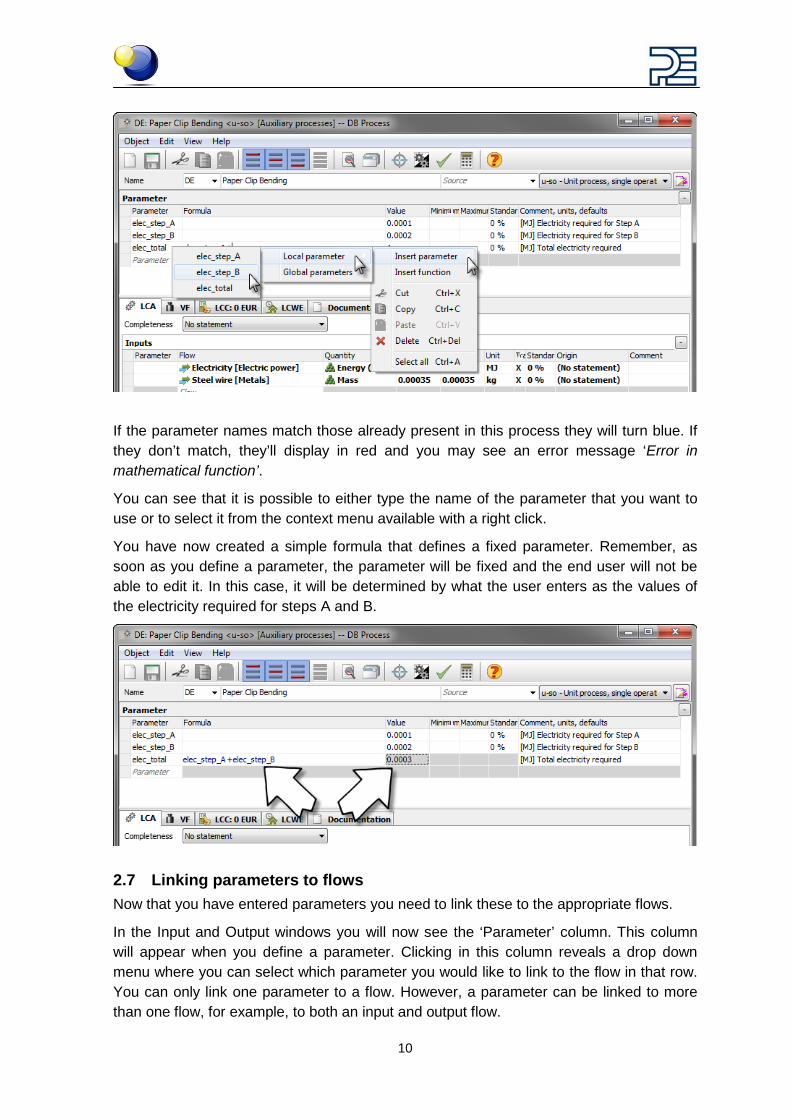
Now right click and select ‘Insert parameter’, then ‘Local parameter’ and click ‘elec_step_B’
10
If the parameter names match those already present in this process they will turn blue. If they don’t match, they’ll display in red and you may see an error message ‘Error in mathematical function’.
You can see that it is possible to either type the name of the parameter that you want to use or to select it from the context menu available with a right click.
You have now created a simple formula that defines a fixed parameter. Remember, as soon as you define a parameter, the parameter will be fixed and the end user will not be able to edit it. In this case, it will be determined by what the user enters as the values of the electricity required for steps A and B.
2.7 Linking parameters to flows Now that you have entered parameters you need to link these to the appropriate flows.
In the Input and Output windows you will now see the ‘Parameter’ column. This column will appear when you define a parameter. Clicking in this column reveals a drop down menu where you can select which parameter you would like to link to the flow in that row. You can only link one parameter to a flow. However, a parameter can be linked to more than one flow, for example, to both an input and output flow.
11
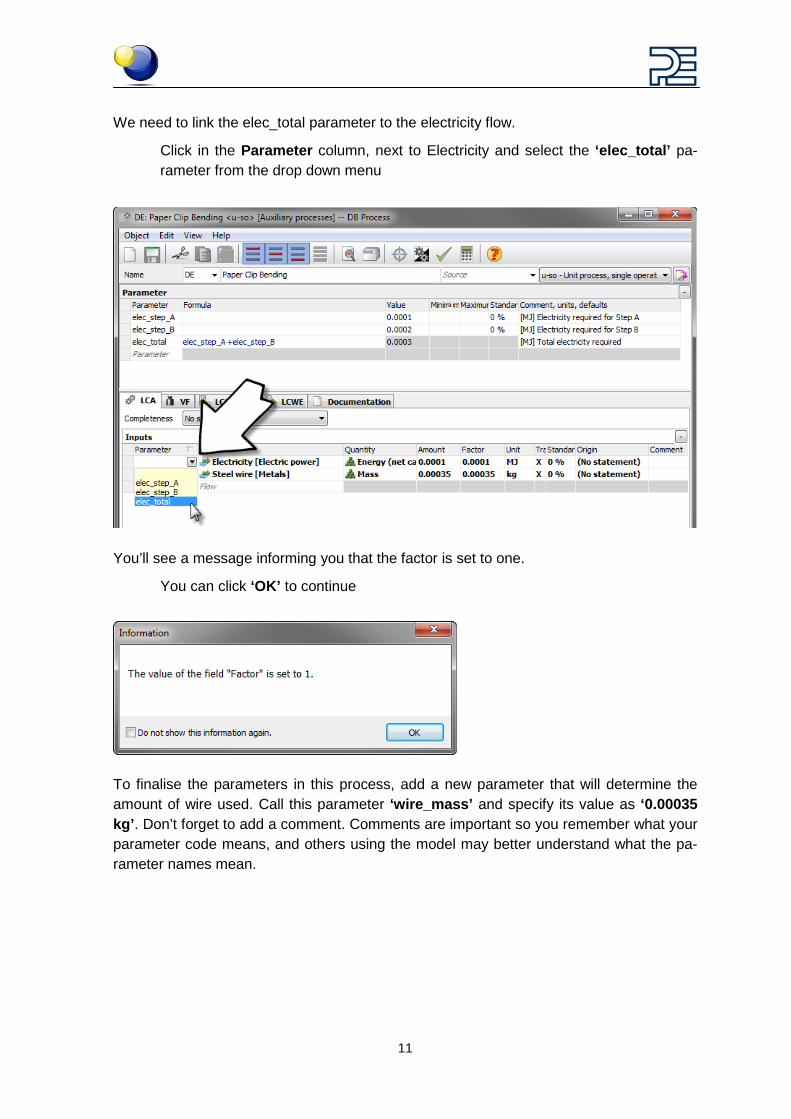
We need to link the elec_total parameter to the electricity flow.
Click in the Parameter column, next to Electricity and select the ‘elec_total’ pa-rameter from the drop down menu
You’ll see a message informing you that the factor is set to one.
You can click ‘OK’ to continue
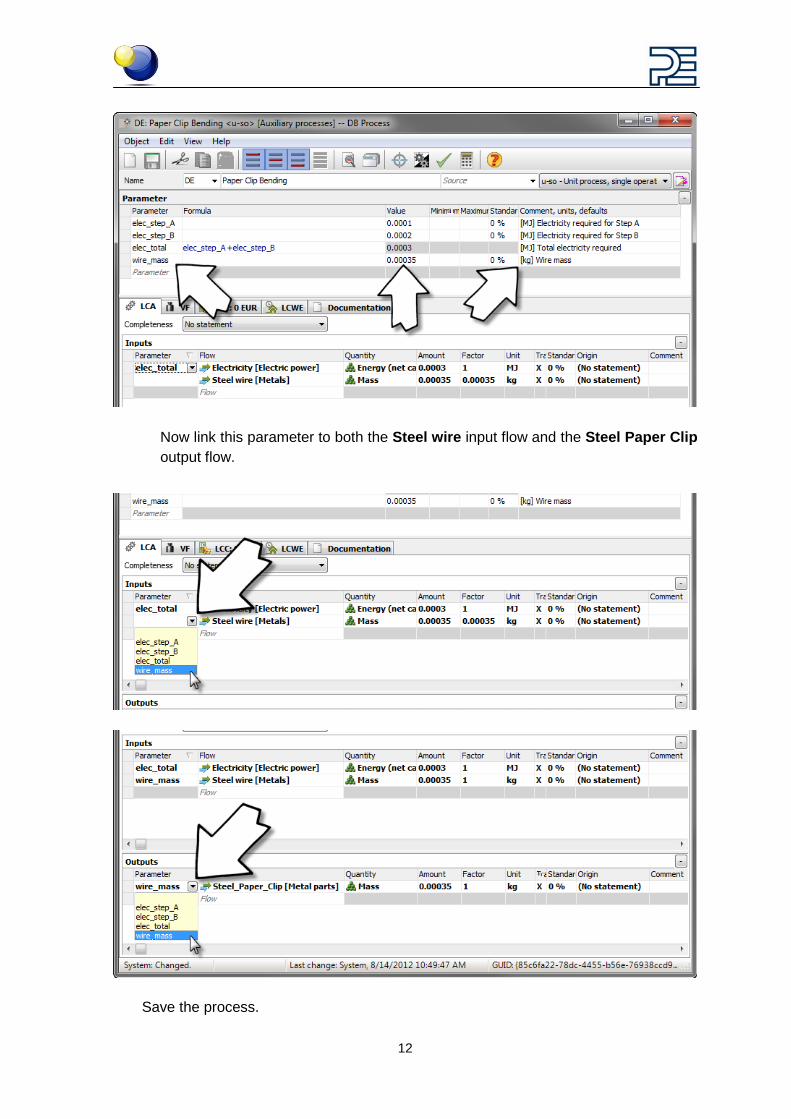
To finalise the parameters in this process, add a new parameter that will determine the amount of wire used. Call this parameter ‘wire_mass’ and specify its value as ‘0.00035 kg’. Don’t forget to add a comment. Comments are important so you remember what your parameter code means, and others using the model may better understand what the pa-rameter names mean.
12
Now link this parameter to both the Steel wire input flow and the Steel Paper Clip output flow.
Save the process.
13
3 Building the scenario interface
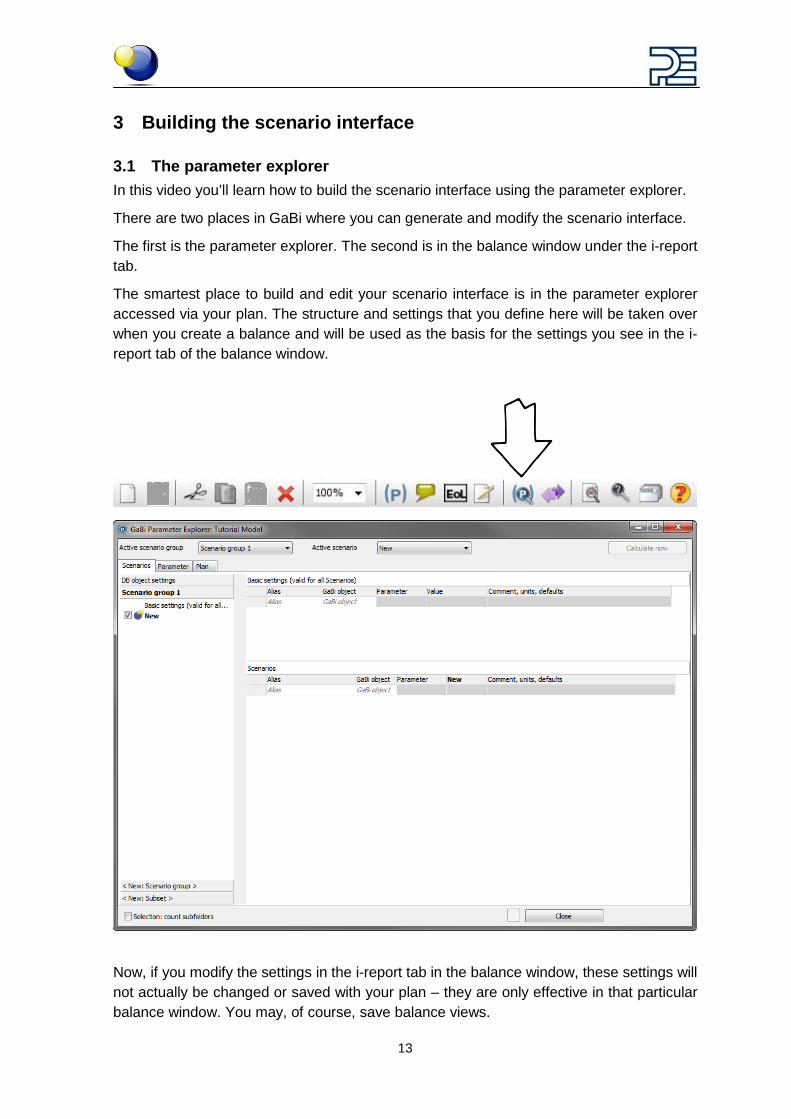
3.1 The parameter explorer In this video you’ll learn how to build the scenario interface using the parameter explorer.
There are two places in GaBi where you can generate and modify the scenario interface.
The first is the parameter explorer. The second is in the balance window under the i-report tab.
The smartest place to build and edit your scenario interface is in the parameter explorer accessed via your plan. The structure and settings that you define here will be taken over when you create a balance and will be used as the basis for the settings you see in the i-report tab of the balance window.
Now, if you modify the settings in the i-report tab in the balance window, these settings will not actually be changed or saved with your plan – they are only effective in that particular balance window. You may, of course, save balance views.
14
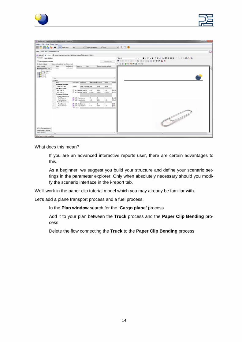
What does this mean?
If you are an advanced interactive reports user, there are certain advantages to this.
As a beginner, we suggest you build your structure and define your scenario set-tings in the parameter explorer. Only when absolutely necessary should you modi-fy the scenario interface in the i-report tab.
We’ll work in the paper clip tutorial model which you may already be familiar with.
Let’s add a plane transport process and a fuel process.
In the Plan window search for the ‘Cargo plane’ process
Add it to your plan between the Truck process and the Paper Clip Bending pro-cess
Delete the flow connecting the Truck to the Paper Clip Bending process
15
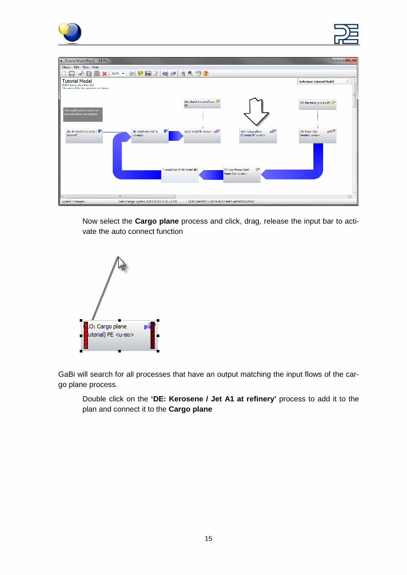
Now select the Cargo plane process and click, drag, release the input bar to acti-vate the auto connect function
GaBi will search for all processes that have an output matching the input flows of the car-go plane process.
Double click on the ‘DE: Kerosene / Jet A1 at refinery’ process to add it to the plan and connect it to the Cargo plane
16
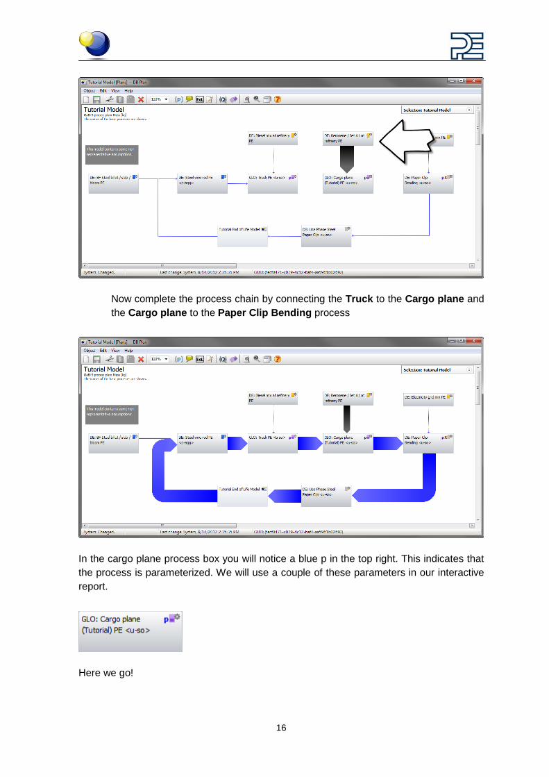
Now complete the process chain by connecting the Truck to the Cargo plane and the Cargo plane to the Paper Clip Bending process
In the cargo plane process box you will notice a blue p in the top right. This indicates that the process is parameterized. We will use a couple of these parameters in our interactive report.
Here we go!
17
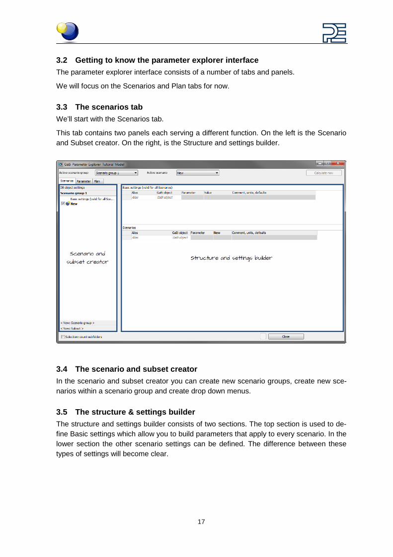
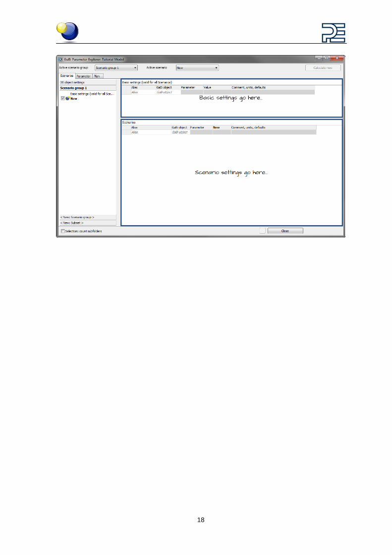
3.2 Getting to know the parameter explorer interface The parameter explorer interface consists of a number of tabs and panels.
We will focus on the Scenarios and Plan tabs for now.
3.3 The scenarios tab We’ll start with the Scenarios tab.
This tab contains two panels each serving a different function. On the left is the Scenario and Subset creator. On the right, is the Structure and settings builder.
3.4 The scenario and subset creator In the scenario and subset creator you can create new scenario groups, create new sce-narios within a scenario group and create drop down menus.
3.5 The structure & settings builder The structure and settings builder consists of two sections. The top section is used to de-fine Basic settings which allow you to build parameters that apply to every scenario. In the lower section the other scenario settings can be defined. The difference between these types of settings will become clear.
18
19
4 Creating scenario groups and scenarios Let’s take a look at how you can create scenarios, subsets and build the scenario inter-faces characteristics.
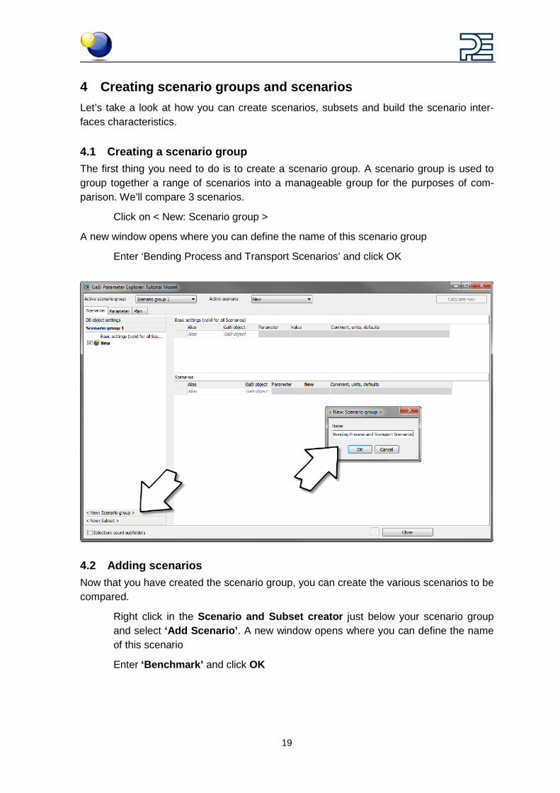
4.1 Creating a scenario group The first thing you need to do is to create a scenario group. A scenario group is used to group together a range of scenarios into a manageable group for the purposes of com-parison. We’ll compare 3 scenarios.
Click on < New: Scenario group >
A new window opens where you can define the name of this scenario group
Enter ‘Bending Process and Transport Scenarios’ and click OK
4.2 Adding scenarios Now that you have created the scenario group, you can create the various scenarios to be compared.
Right click in the Scenario and Subset creator just below your scenario group and select ‘Add Scenario’. A new window opens where you can define the name of this scenario
Enter ‘Benchmark’ and click OK

20
You can repeat this procedure until you have added all your scenarios.
Enter a new scenario called ‘Option 1’
And enter ‘Option 2’
21
5 Establishing the i-report start settings You have now started a scenario group called ‘Bending Process and Transport Scenarios’ containing three scenarios; ‘Benchmark, Option 1 and Option 2’.
For the end user to be able to modify the free parameters that you defined in the model you need to make them available and structure them in a usable way within the scenario interface.
Here’s how:
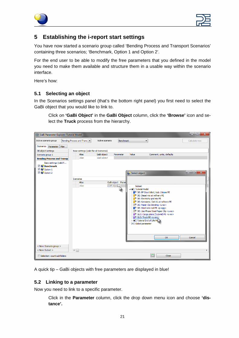
5.1 Selecting an object In the Scenarios settings panel (that’s the bottom right panel) you first need to select the GaBi object that you would like to link to.
Click on ‘GaBi Object’ in the GaBi Object column, click the ‘Browse’ icon and se-lect the Truck process from the hierarchy.
A quick tip – GaBi objects with free parameters are displayed in blue!
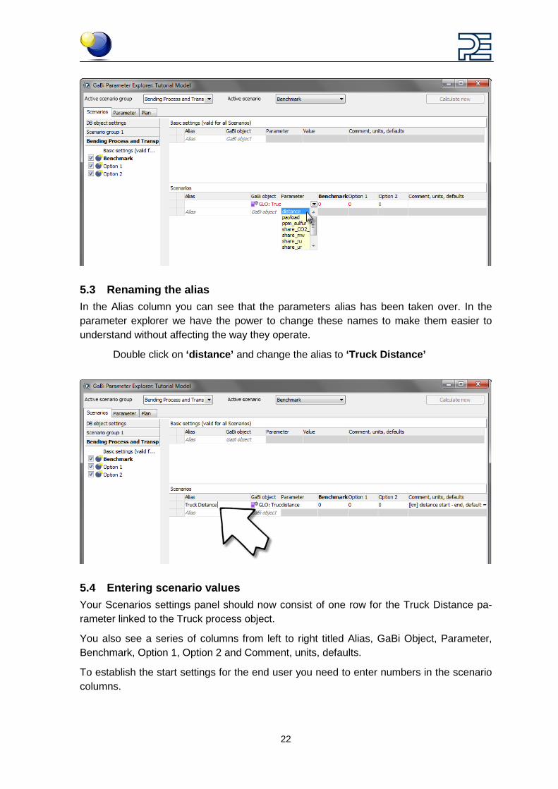
5.2 Linking to a parameter Now you need to link to a specific parameter.
Click in the Parameter column, click the drop down menu icon and choose ‘dis-tance’.
22
5.3 Renaming the alias In the Alias column you can see that the parameters alias has been taken over. In the parameter explorer we have the power to change these names to make them easier to understand without affecting the way they operate.
Double click on ‘distance’ and change the alias to ‘Truck Distance’
5.4 Entering scenario values Your Scenarios settings panel should now consist of one row for the Truck Distance pa-rameter linked to the Truck process object.
You also see a series of columns from left to right titled Alias, GaBi Object, Parameter, Benchmark, Option 1, Option 2 and Comment, units, defaults.
To establish the start settings for the end user you need to enter numbers in the scenario columns.
23
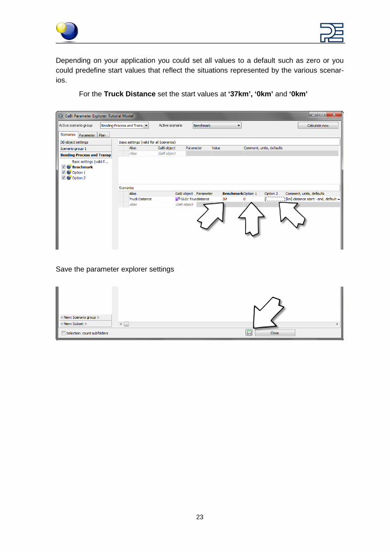
Depending on your application you could set all values to a default such as zero or you could predefine start values that reflect the situations represented by the various scenar-ios.
For the Truck Distance set the start values at ‘37km’, ‘0km’ and ‘0km’
Save the parameter explorer settings
24
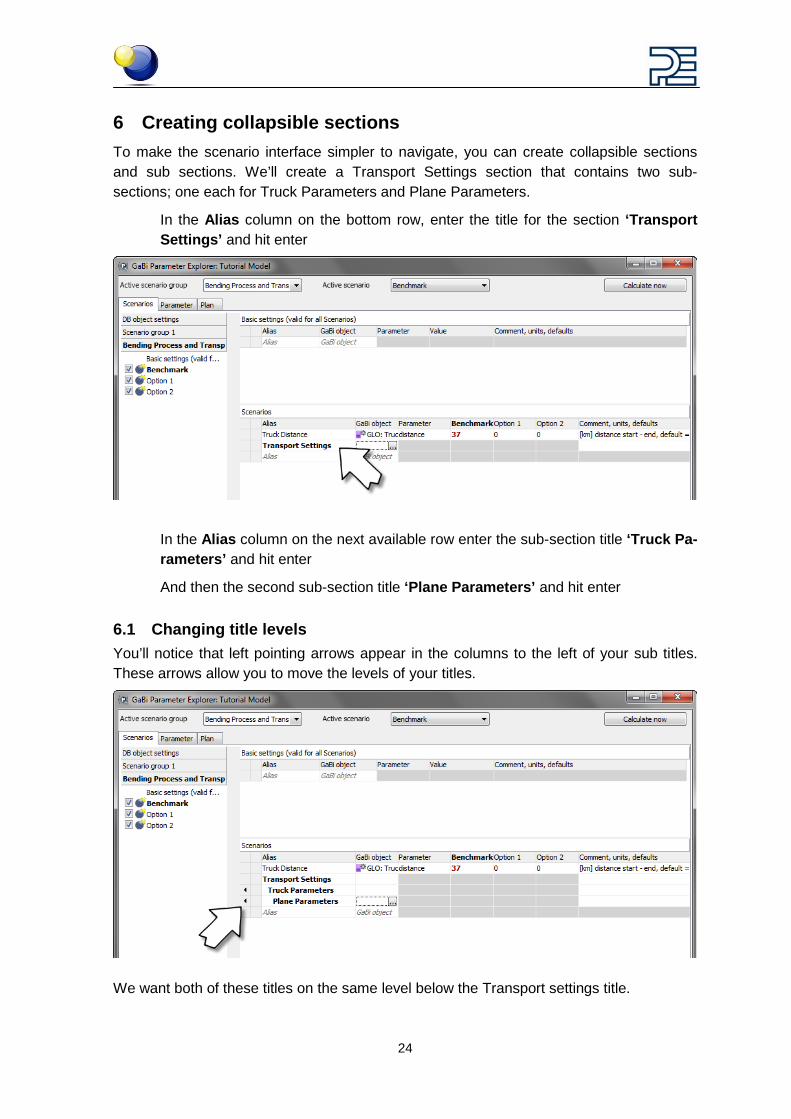
6 Creating collapsible sections To make the scenario interface simpler to navigate, you can create collapsible sections and sub sections. We’ll create a Transport Settings section that contains two sub-sections; one each for Truck Parameters and Plane Parameters.
In the Alias column on the bottom row, enter the title for the section ‘Transport Settings’ and hit enter
In the Alias column on the next available row enter the sub-section title ‘Truck Pa-rameters’ and hit enter
And then the second sub-section title ‘Plane Parameters’ and hit enter
6.1 Changing title levels You’ll notice that left pointing arrows appear in the columns to the left of your sub titles. These arrows allow you to move the levels of your titles.
We want both of these titles on the same level below the Transport settings title.
25
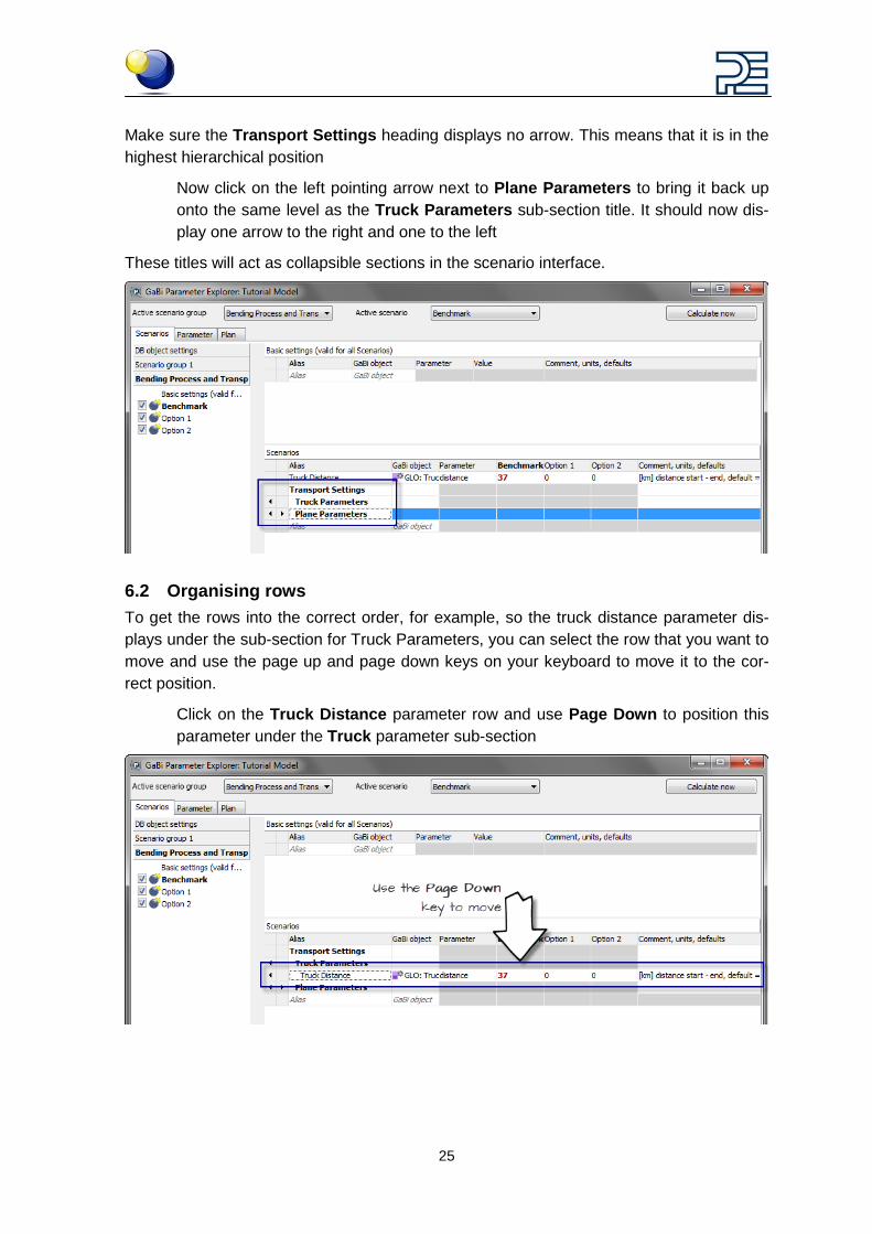
Make sure the Transport Settings heading displays no arrow. This means that it is in the highest hierarchical position
Now click on the left pointing arrow next to Plane Parameters to bring it back up onto the same level as the Truck Parameters sub-section title. It should now dis-play one arrow to the right and one to the left
These titles will act as collapsible sections in the scenario interface.
6.2 Organising rows To get the rows into the correct order, for example, so the truck distance parameter dis-plays under the sub-section for Truck Parameters, you can select the row that you want to move and use the page up and page down keys on your keyboard to move it to the cor-rect position.
Click on the Truck Distance parameter row and use Page Down to position this parameter under the Truck parameter sub-section
26
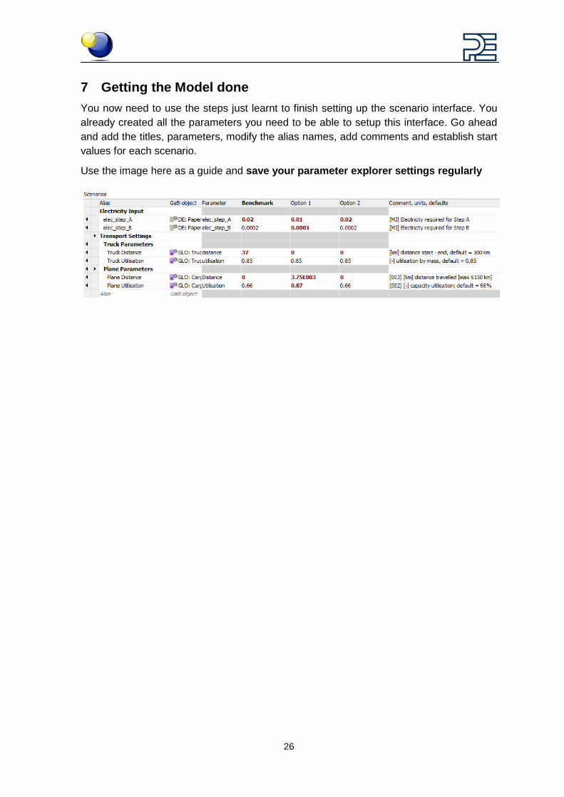
7 Getting the Model done You now need to use the steps just learnt to finish setting up the scenario interface. You already created all the parameters you need to be able to setup this interface. Go ahead and add the titles, parameters, modify the alias names, add comments and establish start values for each scenario.
Use the image here as a guide and save your parameter explorer settings regularly

27
8 Creating drop-down menus
8.1 Creating a subset In GaBi we use the word ‘subsets’ to describe what are essentially ‘drop-down’ menus. Subsets are very powerful because they allow the end user to simply choose a predefined value from a drop down list instead of entering a value.
These can be very useful where the end user should simply choose from some predefined options, for example where the characteristics of alternative designs are predefined, or where the end user should be limited in choice.
They can also be useful for grouping predefined sets of parameters together, for example all parameter settings related to a particular manufacturing site including electricity type, transport distances, water usage and so on.
A typical use of subsets involves creating a drop down menu such that the end user can select a transport method.
We’ll assume that there are two paper clip designs – one large, one small. We can use a subset to create a drop down menu such that our non-LCA professionals can simply choose to analyse these two paper clip designs without having to know any more informa-tion about the individual designs.
In the Parameter Explorer, select the Scenarios tab and in the Scenario and Sub-set Creator click on ‘New Subset’
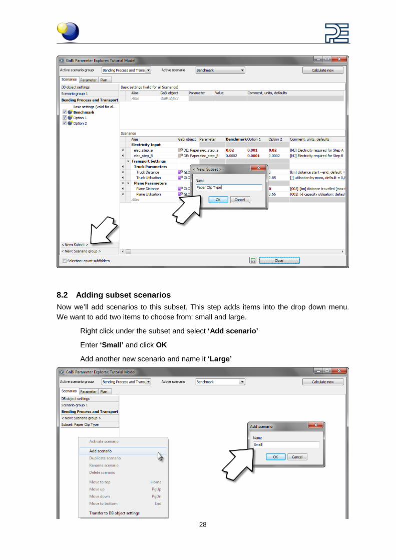
In the popup window, enter the name of your new dropdown menu. Call this one ‘Paper Clip Type’ and hit enter or click OK
28
8.2 Adding subset scenarios Now we’ll add scenarios to this subset. This step adds items into the drop down menu. We want to add two items to choose from: small and large.
Right click under the subset and select ‘Add scenario’
Enter ‘Small’ and click OK
Add another new scenario and name it ‘Large’
29
We’ve now added the two options that will be shown in the drop down list. If you’d like to add additional paper clip design options you could keep adding them here. For example, for a medium sized design.
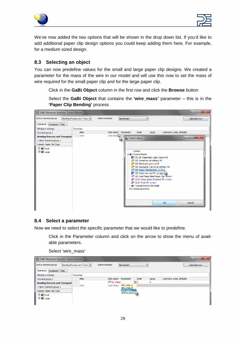
8.3 Selecting an object You can now predefine values for the small and large paper clip designs. We created a parameter for the mass of the wire in our model and will use this now to set the mass of wire required for the small paper clip and for the large paper clip.
Click in the GaBi Object column in the first row and click the Browse button
Select the GaBi Object that contains the ‘wire_mass’ parameter – this is in the ‘Paper Clip Bending’ process
8.4 Select a parameter Now we need to select the specific parameter that we would like to predefine.
Click in the Parameter column and click on the arrow to show the menu of avail-able parameters.
Select ‘wire_mass’
30
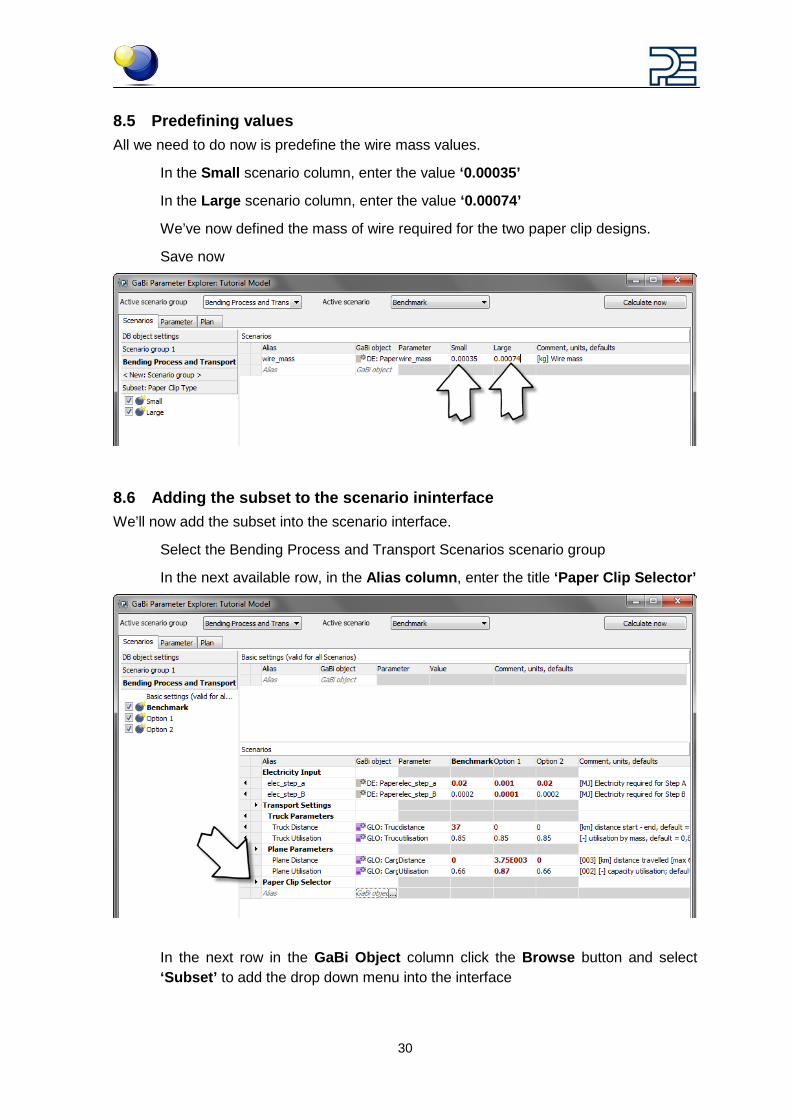
8.5 Predefining values All we need to do now is predefine the wire mass values.
In the Small scenario column, enter the value ‘0.00035’
In the Large scenario column, enter the value ‘0.00074’
We’ve now defined the mass of wire required for the two paper clip designs.
Save now
8.6 Adding the subset to the scenario ininterface We’ll now add the subset into the scenario interface.
Select the Bending Process and Transport Scenarios scenario group
In the next available row, in the Alias column, enter the title ‘Paper Clip Selector’
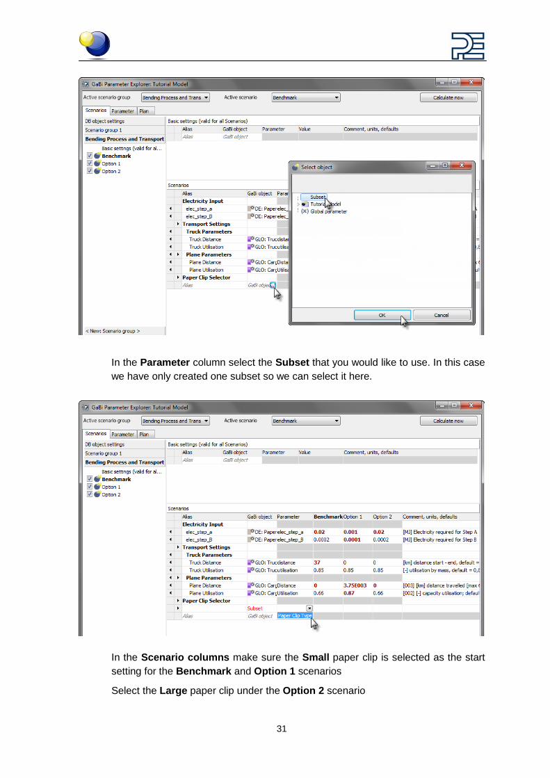
In the next row in the GaBi Object column click the Browse button and select ‘Subset’ to add the drop down menu into the interface
31
In the Parameter column select the Subset that you would like to use. In this case we have only created one subset so we can select it here.
In the Scenario columns make sure the Small paper clip is selected as the start setting for the Benchmark and Option 1 scenarios
Select the Large paper clip under the Option 2 scenario
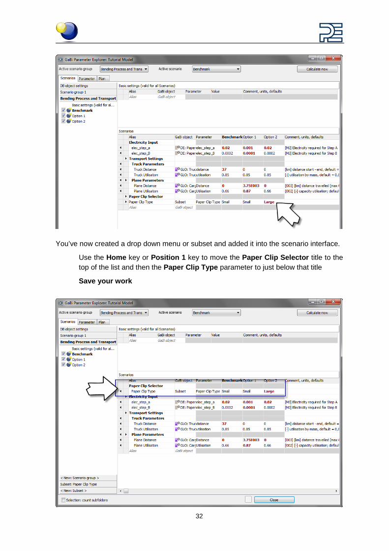
32
You’ve now created a drop down menu or subset and added it into the scenario interface.
Use the Home key or Position 1 key to move the Paper Clip Selector title to the top of the list and then the Paper Clip Type parameter to just below that title
Save your work
33
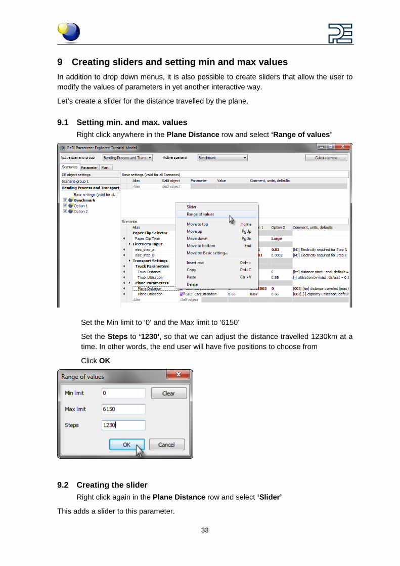
9 Creating sliders and setting min and max values In addition to drop down menus, it is also possible to create sliders that allow the user to modify the values of parameters in yet another interactive way.
Let’s create a slider for the distance travelled by the plane.
9.1 Setting min. and max. values Right click anywhere in the Plane Distance row and select ‘Range of values’
Set the Min limit to ‘0’ and the Max limit to ‘6150’
Set the Steps to ‘1230’, so that we can adjust the distance travelled 1230km at a time. In other words, the end user will have five positions to choose from
Click OK
9.2 Creating the slider Right click again in the Plane Distance row and select ‘Slider’
This adds a slider to this parameter.
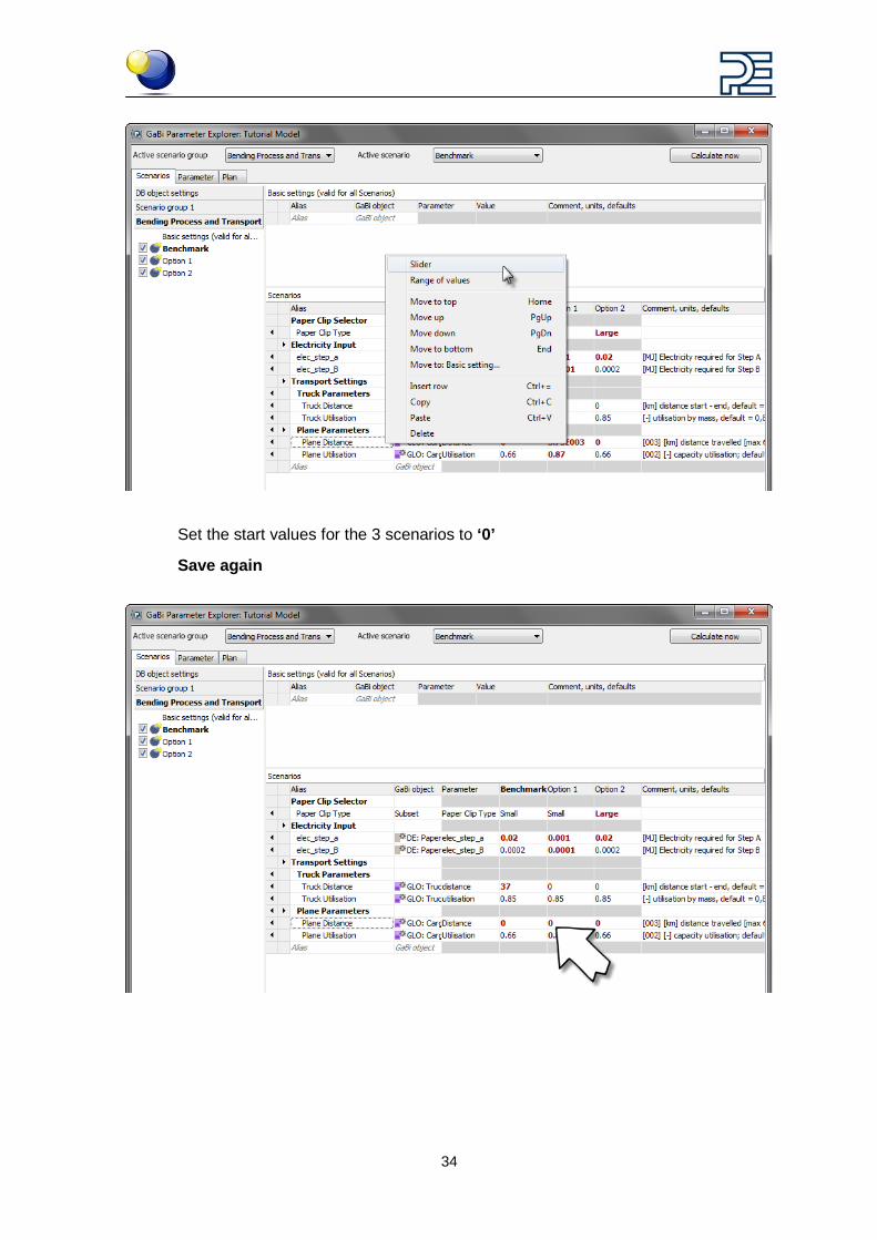
34
Set the start values for the 3 scenarios to ‘0’
Save again
35
10 Activating a scenario, viewing the plan and the LCIA preview
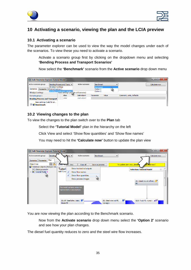
10.1 Activating a scenario The parameter explorer can be used to view the way the model changes under each of the scenarios. To view these you need to activate a scenario.
Activate a scenario group first by clicking on the dropdown menu and selecting ‘Bending Process and Transport Scenarios’
Now select the ‘Benchmark’ scenario from the Active scenario drop down menu
10.2 Viewing changes to the plan To view the changes to the plan switch over to the Plan tab
Select the ‘Tutorial Model’ plan in the hierarchy on the left
Click View and select ‘Show flow quantities’ and ‘Show flow names’
You may need to hit the ‘Calculate now’ button to update the plan view
You are now viewing the plan according to the Benchmark scenario.
Now from the Activate scenario drop down menu select the ‘Option 2’ scenario and see how your plan changes.
The diesel fuel quantity reduces to zero and the steel wire flow increases.
36
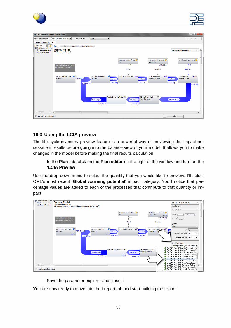
10.3 Using the LCIA preview The life cycle inventory preview feature is a powerful way of previewing the impact as-sessment results before going into the balance view of your model. It allows you to make changes in the model before making the final results calculation.
In the Plan tab, click on the Plan editor on the right of the window and turn on the ‘LCIA Preview’
Use the drop down menu to select the quantity that you would like to preview. I’ll select CML’s most recent ‘Global warming potential’ impact category. You’ll notice that per-centage values are added to each of the processes that contribute to that quantity or im-pact
Save the parameter explorer and close it
You are now ready to move into the i-report tab and start building the report.
37
11 Creating an i-report with an existing template
11.1 How can I create an i-report with an existing template: It is not always necessary to build a new report from scratch.
Once you create reports you can save them as templates for use on other models.
PE INTERNATIONAL can also provide you with pre-made report templates that allow you to simply add your results to the tables for communication through a report.
We prepared one for you to finish.
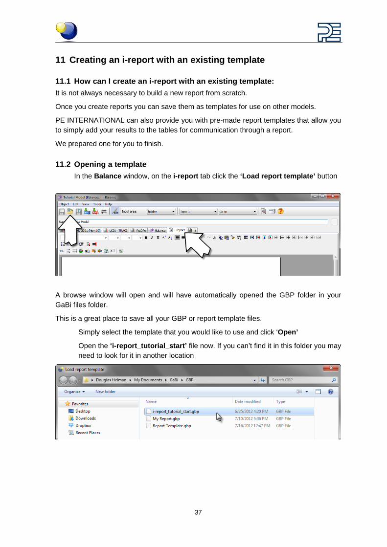
11.2 Opening a template In the Balance window, on the i-report tab click the ‘Load report template’ button
A browse window will open and will have automatically opened the GBP folder in your GaBi files folder.
This is a great place to save all your GBP or report template files.
Simply select the template that you would like to use and click ‘Open’
Open the ‘i-report_tutorial_start’ file now. If you can’t find it in this folder you may need to look for it in another location
38
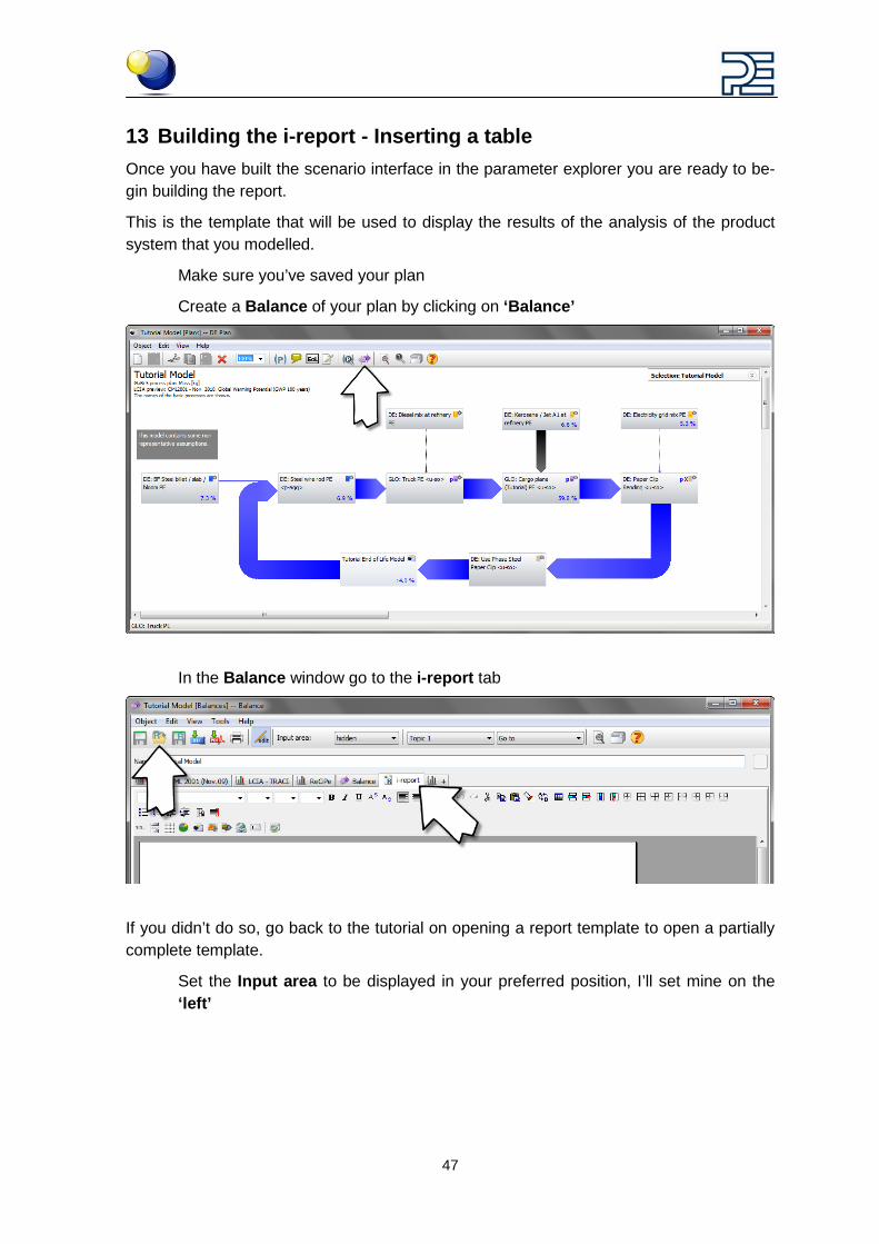
12 Building the i-report - Inserting a diagram Once you have built the scenario interface in the parameter explorer you are ready to be-gin building the report.
This is the template that will be used to display the results of the analysis of the product system that you modelled.
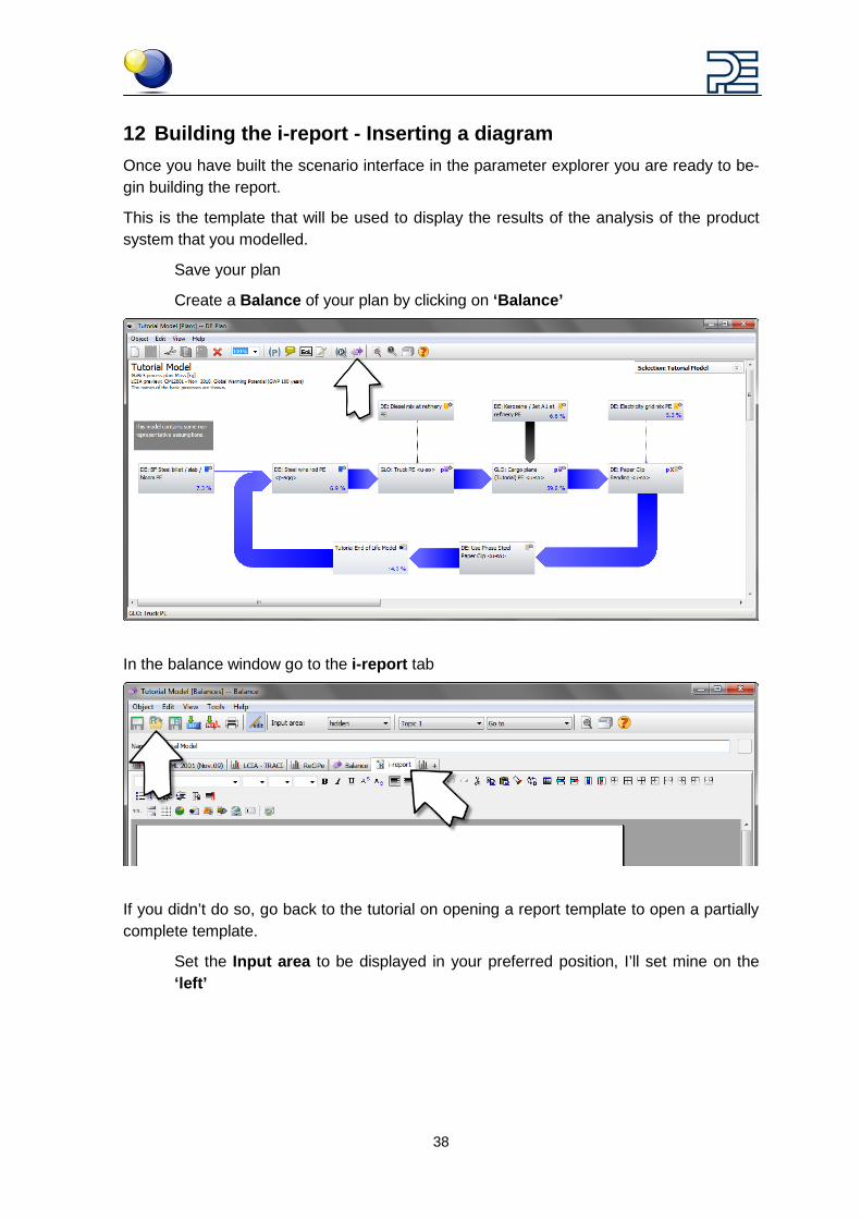
Save your plan
Create a Balance of your plan by clicking on ‘Balance’
In the balance window go to the i-report tab
If you didn’t do so, go back to the tutorial on opening a report template to open a partially complete template.
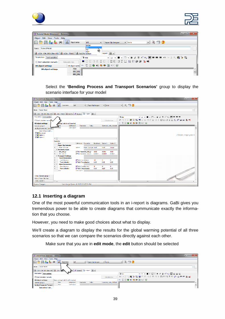
Set the Input area to be displayed in your preferred position, I’ll set mine on the ‘left’
39
Select the ‘Bending Process and Transport Scenarios’ group to display the scenario interface for your model
12.1 Inserting a diagram One of the most powerful communication tools in an i-report is diagrams. GaBi gives you tremendous power to be able to create diagrams that communicate exactly the informa-tion that you choose.
However, you need to make good choices about what to display.
We’ll create a diagram to display the results for the global warming potential of all three scenarios so that we can compare the scenarios directly against each other.
Make sure that you are in edit mode, the edit button should be selected
40
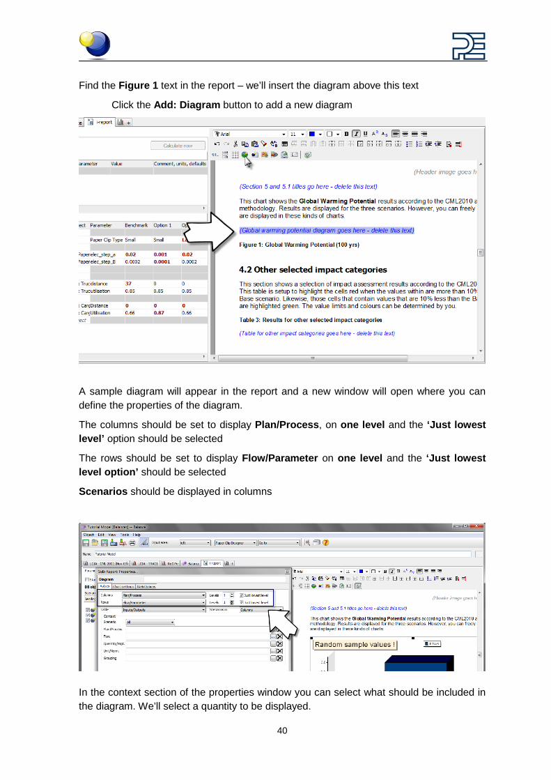
Find the Figure 1 text in the report – we’ll insert the diagram above this text
Click the Add: Diagram button to add a new diagram
A sample diagram will appear in the report and a new window will open where you can define the properties of the diagram.
The columns should be set to display Plan/Process, on one level and the ‘Just lowest level’ option should be selected
The rows should be set to display Flow/Parameter on one level and the ‘Just lowest level option’ should be selected
Scenarios should be displayed in columns
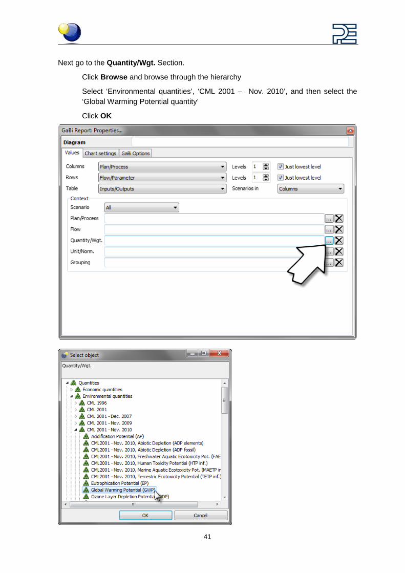
In the context section of the properties window you can select what should be included in the diagram. We’ll select a quantity to be displayed.
41
Next go to the Quantity/Wgt. Section.
Click Browse and browse through the hierarchy
Select ‘Environmental quantities’, ‘CML 2001 – Nov. 2010’, and then select the ‘Global Warming Potential quantity’
Click OK
42
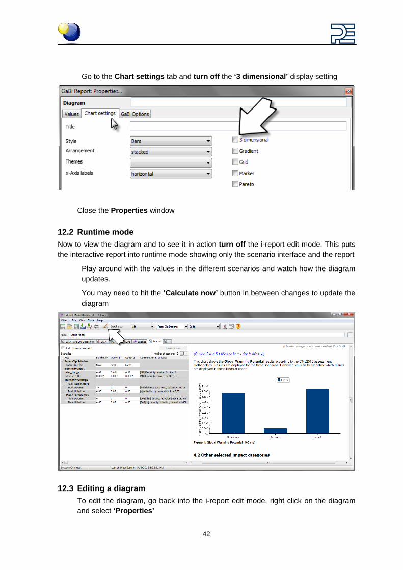
Go to the Chart settings tab and turn off the ‘3 dimensional’ display setting
Close the Properties window
12.2 Runtime mode Now to view the diagram and to see it in action turn off the i-report edit mode. This puts the interactive report into runtime mode showing only the scenario interface and the report
Play around with the values in the different scenarios and watch how the diagram updates.
You may need to hit the ‘Calculate now’ button in between changes to update the diagram
12.3 Editing a diagram To edit the diagram, go back into the i-report edit mode, right click on the diagram and select ‘Properties’
43
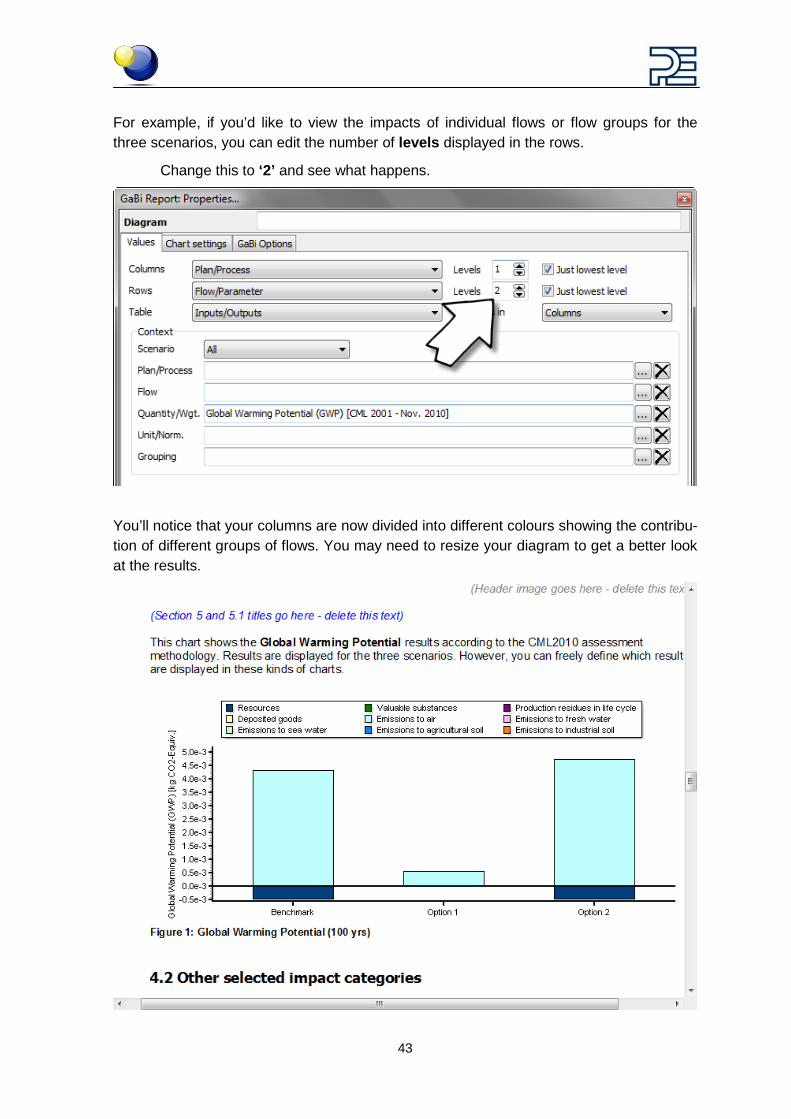
For example, if you’d like to view the impacts of individual flows or flow groups for the three scenarios, you can edit the number of levels displayed in the rows.
Change this to ‘2’ and see what happens.
You’ll notice that your columns are now divided into different colours showing the contribu-tion of different groups of flows. You may need to resize your diagram to get a better look at the results.
44
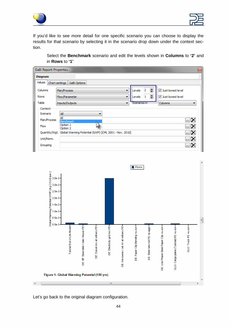
If you’d like to see more detail for one specific scenario you can choose to display the results for that scenario by selecting it in the scenario drop down under the context sec-tion.
Select the Benchmark scenario and edit the levels shown in Columns to ‘2’ and in Rows to ‘1’
Let’s go back to the original diagram configuration.
45
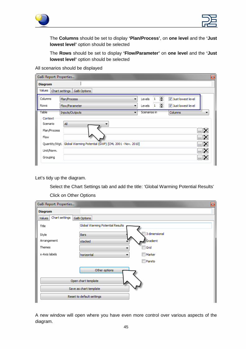
The Columns should be set to display ‘Plan/Process’, on one level and the ‘Just lowest level’ option should be selected
The Rows should be set to display ‘Flow/Parameter’ on one level and the ‘Just lowest level’ option should be selected
All scenarios should be displayed
Let’s tidy up the diagram.
Select the Chart Settings tab and add the title: ‘Global Warming Potential Results’
Click on Other Options
A new window will open where you have even more control over various aspects of the diagram.
46
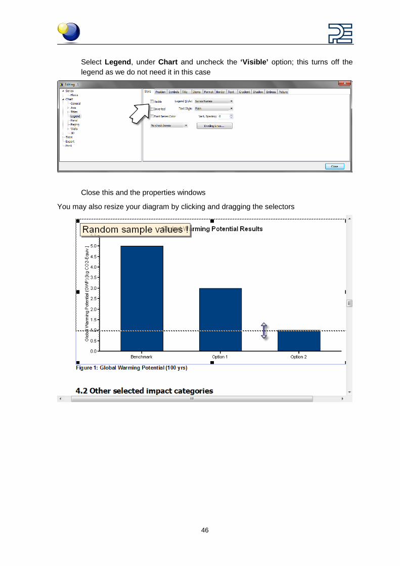
Select Legend, under Chart and uncheck the ‘Visible’ option; this turns off the legend as we do not need it in this case
Close this and the properties windows
You may also resize your diagram by clicking and dragging the selectors
47
13 Building the i-report - Inserting a table Once you have built the scenario interface in the parameter explorer you are ready to be-gin building the report.
This is the template that will be used to display the results of the analysis of the product system that you modelled.
Make sure you’ve saved your plan
Create a Balance of your plan by clicking on ‘Balance’
In the Balance window go to the i-report tab
If you didn’t do so, go back to the tutorial on opening a report template to open a partially complete template.
Set the Input area to be displayed in your preferred position, I’ll set mine on the ‘left’
48
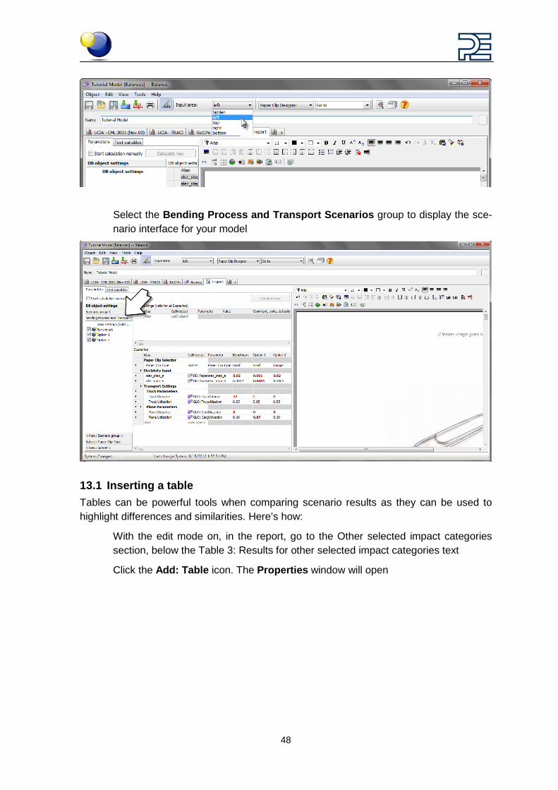
Select the Bending Process and Transport Scenarios group to display the sce-nario interface for your model
13.1 Inserting a table Tables can be powerful tools when comparing scenario results as they can be used to highlight differences and similarities. Here’s how:
With the edit mode on, in the report, go to the Other selected impact categories section, below the Table 3: Results for other selected impact categories text
Click the Add: Table icon. The Properties window will open
49
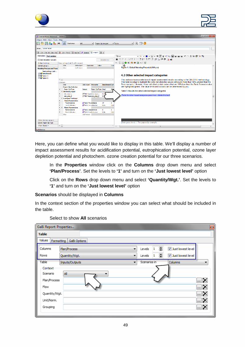
Here, you can define what you would like to display in this table. We’ll display a number of impact assessment results for acidification potential, eutrophication potential, ozone layer depletion potential and photochem. ozone creation potential for our three scenarios.
In the Properties window click on the Columns drop down menu and select ‘Plan/Process’. Set the levels to ‘1’ and turn on the ‘Just lowest level’ option
Click on the Rows drop down menu and select ‘Quantity/Wgt.’. Set the levels to ‘1’ and turn on the ‘Just lowest level’ option
Scenarios should be displayed in Columns
In the context section of the properties window you can select what should be included in the table.
Select to show All scenarios
50
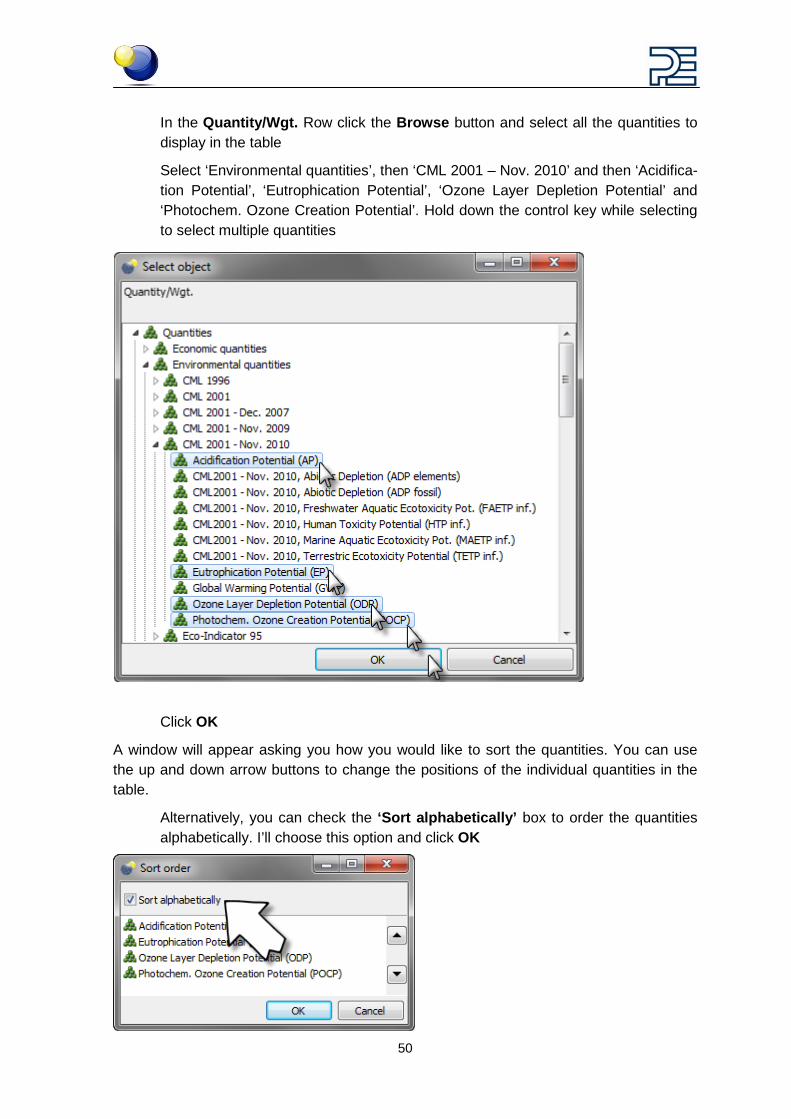
In the Quantity/Wgt. Row click the Browse button and select all the quantities to display in the table
Select ‘Environmental quantities’, then ‘CML 2001 – Nov. 2010’ and then ‘Acidifica-tion Potential’, ‘Eutrophication Potential’, ‘Ozone Layer Depletion Potential’ and ‘Photochem. Ozone Creation Potential’. Hold down the control key while selecting to select multiple quantities
Click OK
A window will appear asking you how you would like to sort the quantities. You can use the up and down arrow buttons to change the positions of the individual quantities in the table.
Alternatively, you can check the ‘Sort alphabetically’ box to order the quantities alphabetically. I’ll choose this option and click OK
51
Close the Properties box and put the i-report in run time mode by coming out of the edit mode
Now you can change the values in the scenario interface and watch the table update ac-cordingly
You may need to hit the Calculate now button in between changes to update the diagram
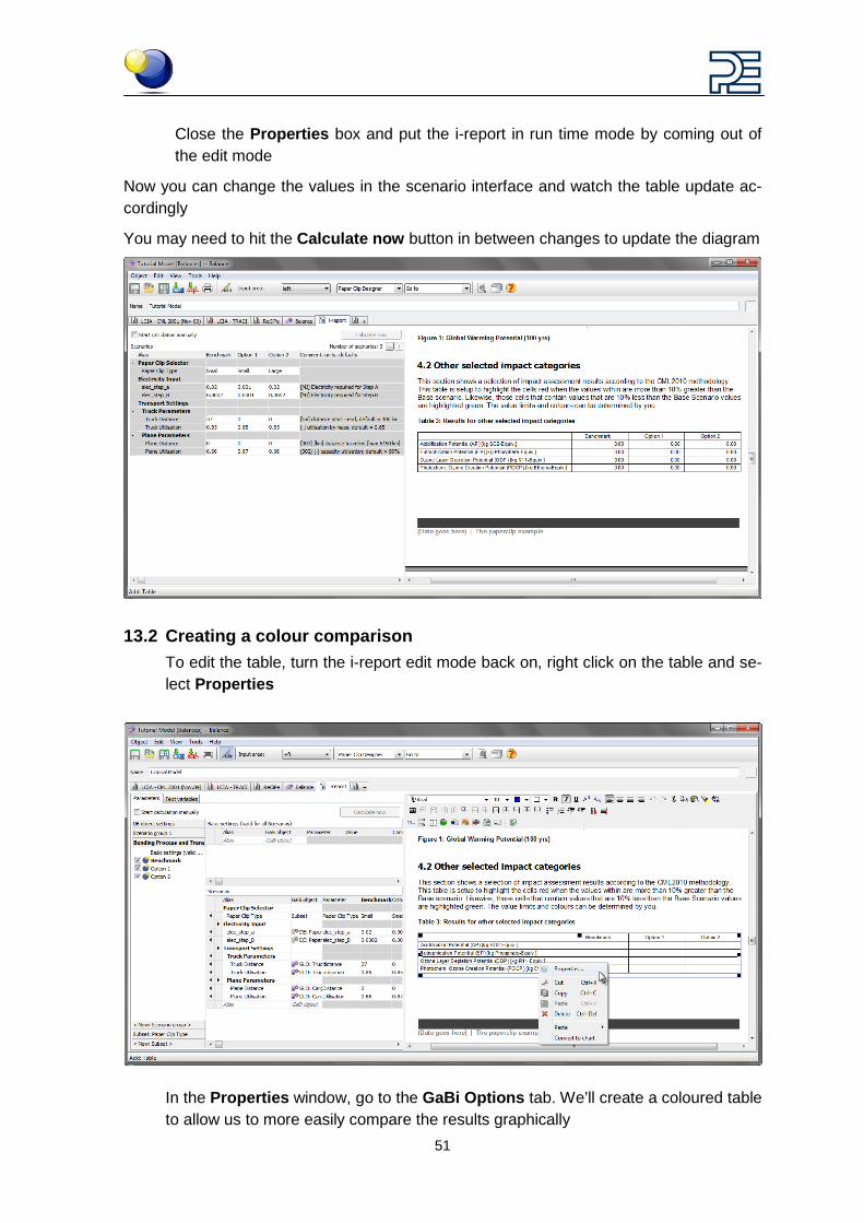
13.2 Creating a colour comparison To edit the table, turn the i-report edit mode back on, right click on the table and se-lect Properties
In the Properties window, go to the GaBi Options tab. We’ll create a coloured table to allow us to more easily compare the results graphically
52
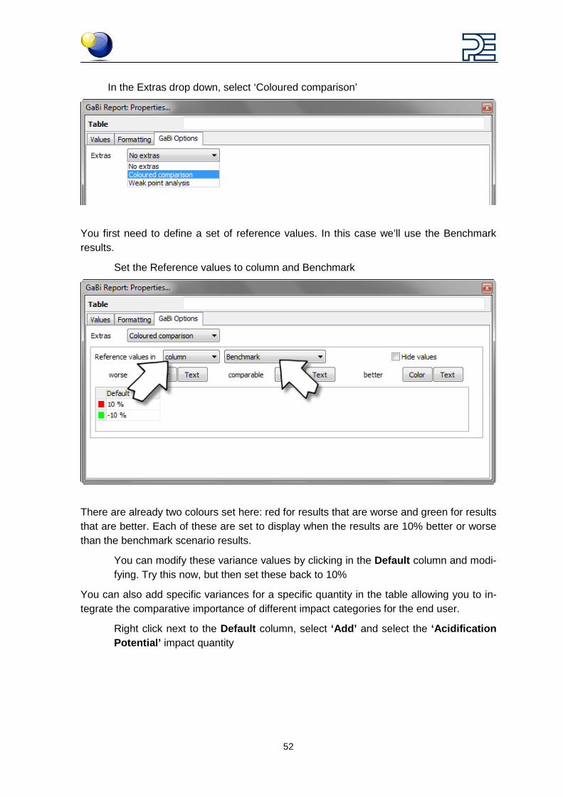
In the Extras drop down, select ‘Coloured comparison’
You first need to define a set of reference values. In this case we’ll use the Benchmark results.
Set the Reference values to column and Benchmark
There are already two colours set here: red for results that are worse and green for results that are better. Each of these are set to display when the results are 10% better or worse than the benchmark scenario results.
You can modify these variance values by clicking in the Default column and modi-fying. Try this now, but then set these back to 10%
You can also add specific variances for a specific quantity in the table allowing you to in-tegrate the comparative importance of different impact categories for the end user.
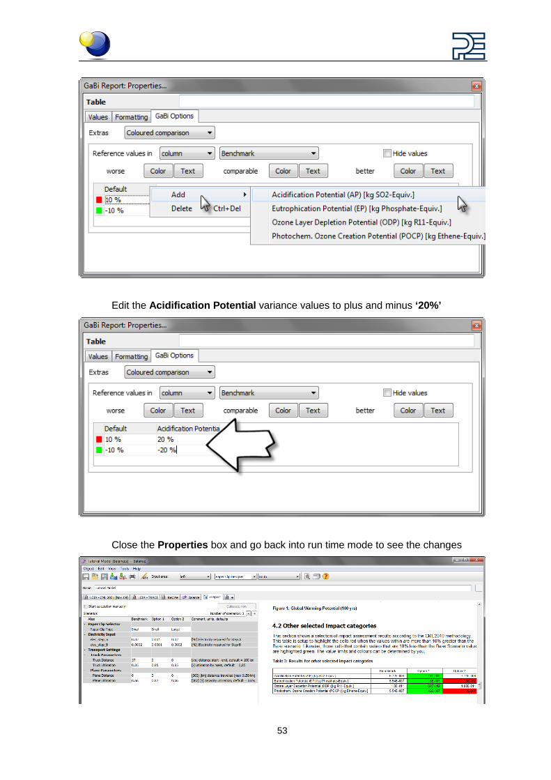
Right click next to the Default column, select ‘Add’ and select the ‘Acidification Potential’ impact quantity
53
Edit the Acidification Potential variance values to plus and minus ‘20%’
Close the Properties box and go back into run time mode to see the changes
54
14 Building the i-report – Structure, appearance and editing
14.1 Introduction After creating the scenario interface, you can build a report template to display the results of the scenario analysis in an easy to understand format that suits your company’s corpo-rate identity.
You already know how to insert the two most important items, diagrams and tables, but there are a bunch of other tools that will help you create the structure and style that you need.
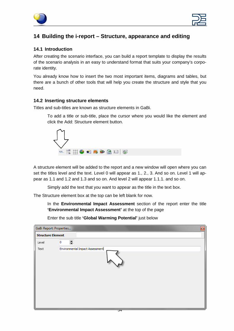
14.2 Inserting structure elements Titles and sub-titles are known as structure elements in GaBi.
To add a title or sub-title, place the cursor where you would like the element and click the Add: Structure element button.
A structure element will be added to the report and a new window will open where you can set the titles level and the text. Level 0 will appear as 1., 2., 3. And so on. Level 1 will ap-pear as 1.1 and 1.2 and 1.3 and so on. And level 2 will appear 1.1.1. and so on.
Simply add the text that you want to appear as the title in the text box.
The Structure element box at the top can be left blank for now.
In the Environmental Impact Assessment section of the report enter the title ‘Environmental Impact Assessment’ at the top of the page
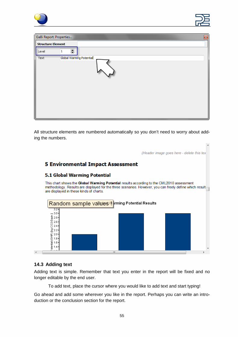
Enter the sub title ‘Global Warming Potential’ just below
55
All structure elements are numbered automatically so you don’t need to worry about add-ing the numbers.
14.3 Adding text Adding text is simple. Remember that text you enter in the report will be fixed and no longer editable by the end user.
To add text, place the cursor where you would like to add text and start typing!
Go ahead and add some wherever you like in the report. Perhaps you can write an intro-duction or the conclusion section for the report.
56
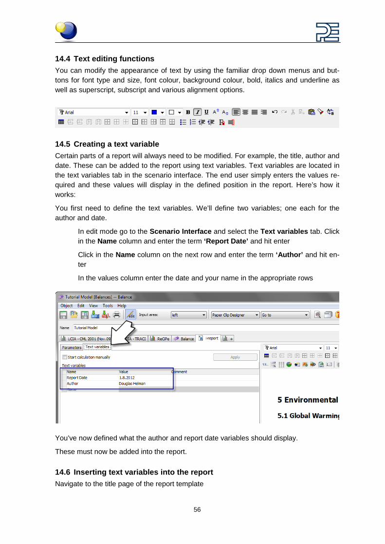
14.4 Text editing functions You can modify the appearance of text by using the familiar drop down menus and but-tons for font type and size, font colour, background colour, bold, italics and underline as well as superscript, subscript and various alignment options.
14.5 Creating a text variable Certain parts of a report will always need to be modified. For example, the title, author and date. These can be added to the report using text variables. Text variables are located in the text variables tab in the scenario interface. The end user simply enters the values re-quired and these values will display in the defined position in the report. Here’s how it works:
You first need to define the text variables. We’ll define two variables; one each for the author and date.
In edit mode go to the Scenario Interface and select the Text variables tab. Click in the Name column and enter the term ‘Report Date’ and hit enter
Click in the Name column on the next row and enter the term ‘Author’ and hit en-ter
In the values column enter the date and your name in the appropriate rows
You’ve now defined what the author and report date variables should display.
These must now be added into the report.
14.6 Inserting text variables into the report Navigate to the title page of the report template
57
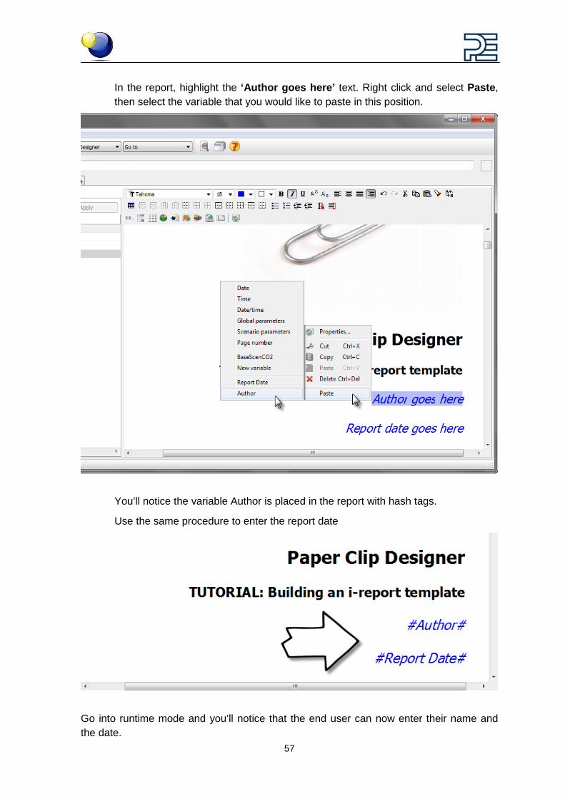
In the report, highlight the ‘Author goes here’ text. Right click and select Paste, then select the variable that you would like to paste in this position.
You’ll notice the variable Author is placed in the report with hash tags.
Use the same procedure to enter the report date
Go into runtime mode and you’ll notice that the end user can now enter their name and the date.

58
14.7 Inserting a plan It can be really beneficial to show an image of your plan in the report. It helps add context and can display useful information.
The plan image will also update as you change the values in the scenario interface.
Inserting a plan is easy.
In edit mode, go to Chapter 3 and click the Add: GaBi 6 process plan button
A new window opens where you can define exactly what should be displayed.
First, select the plan that you would like to insert. Click the Browse button to select it from the hierarchy
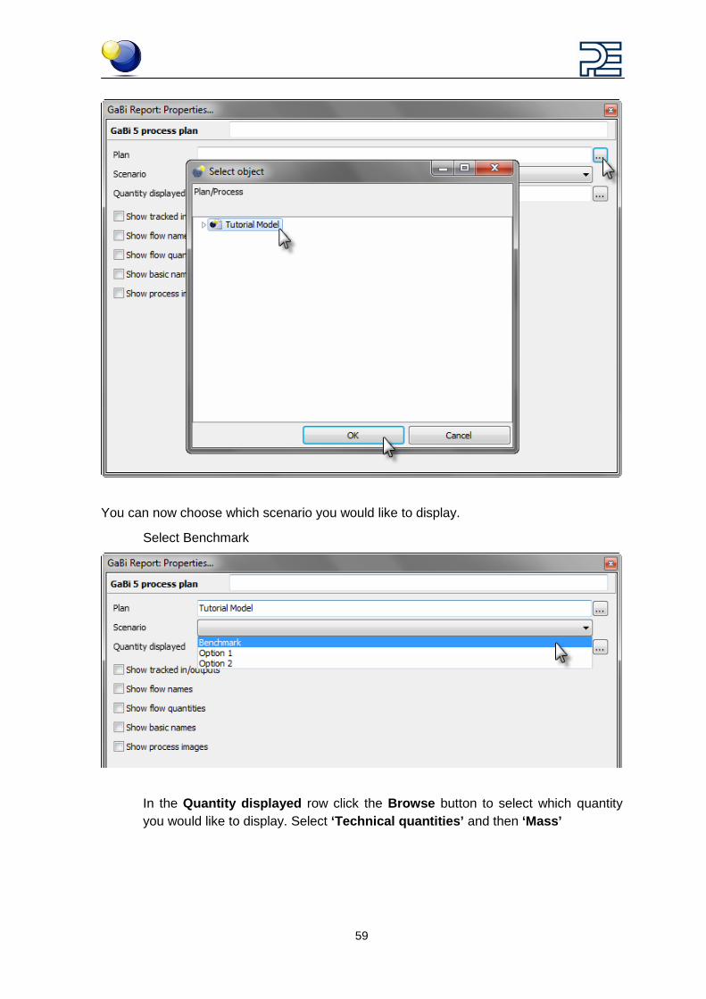
59
You can now choose which scenario you would like to display.
Select Benchmark
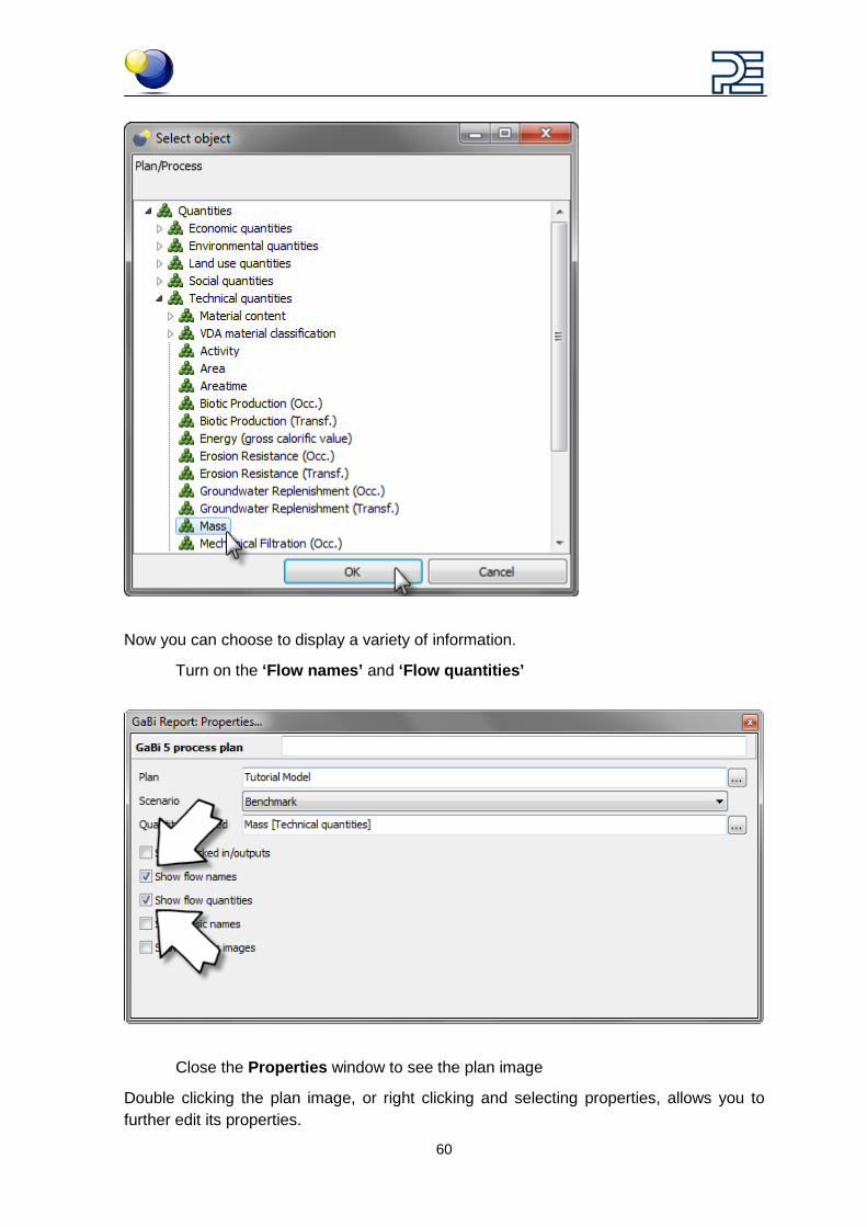
In the Quantity displayed row click the Browse button to select which quantity you would like to display. Select ‘Technical quantities’ and then ‘Mass’
60
Now you can choose to display a variety of information.
Turn on the ‘Flow names’ and ‘Flow quantities’
Close the Properties window to see the plan image
Double clicking the plan image, or right clicking and selecting properties, allows you to further edit its properties.
61
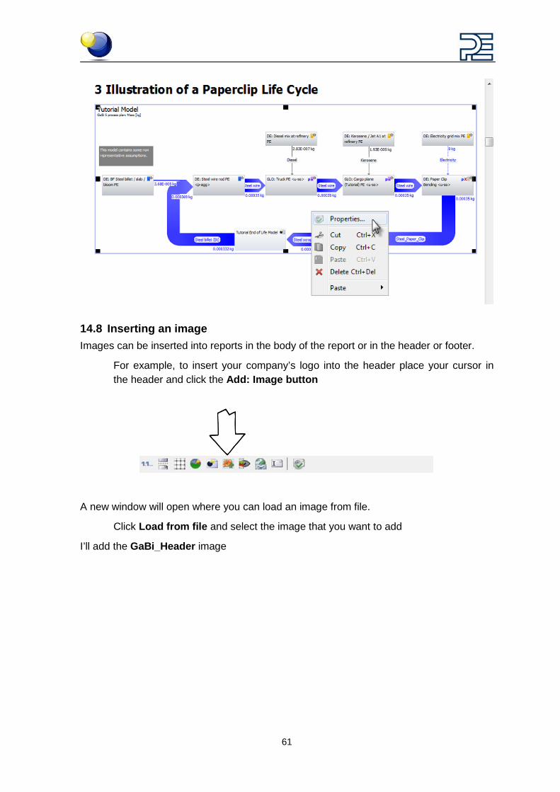
14.8 Inserting an image Images can be inserted into reports in the body of the report or in the header or footer.
For example, to insert your company’s logo into the header place your cursor in the header and click the Add: Image button
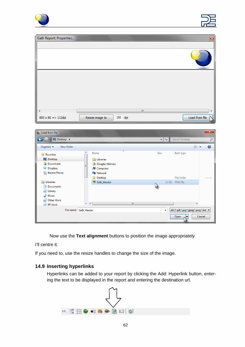
A new window will open where you can load an image from file.
Click Load from file and select the image that you want to add
I’ll add the GaBi_Header image
62
Now use the Text alignment buttons to position the image appropriately
I’ll centre it.
If you need to, use the resize handles to change the size of the image.
14.9 Inserting hyperlinks Hyperlinks can be added to your report by clicking the Add: Hyperlink button, enter-ing the text to be displayed in the report and entering the destination url.
63
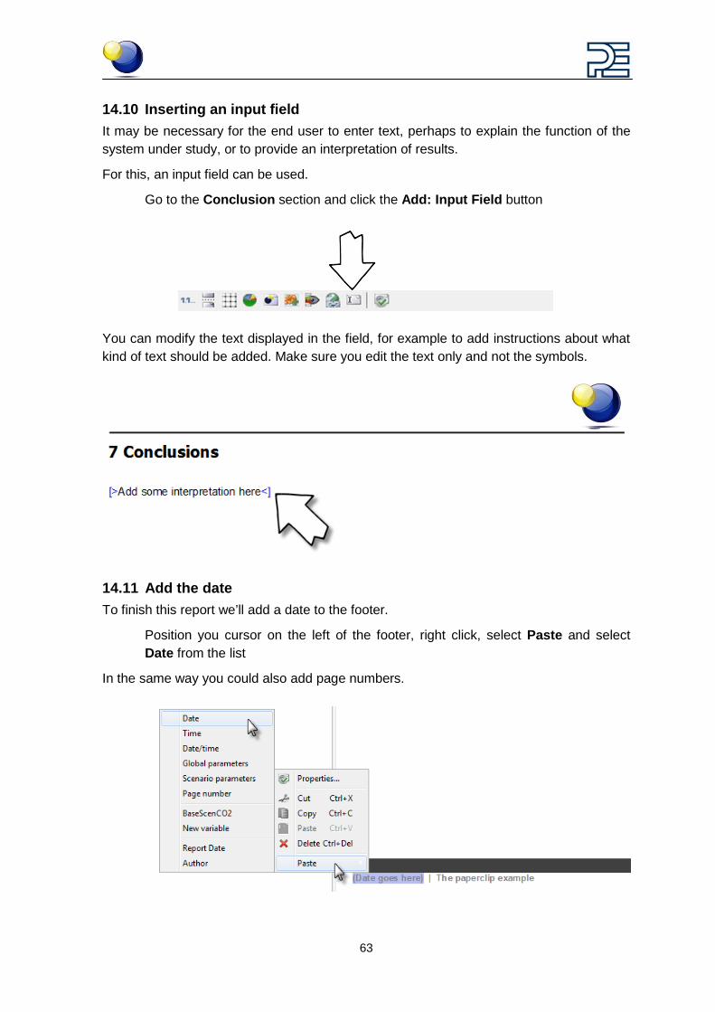
14.10 Inserting an input field It may be necessary for the end user to enter text, perhaps to explain the function of the system under study, or to provide an interpretation of results.
For this, an input field can be used.
Go to the Conclusion section and click the Add: Input Field button
You can modify the text displayed in the field, for example to add instructions about what kind of text should be added. Make sure you edit the text only and not the symbols.
14.11 Add the date To finish this report we’ll add a date to the footer.
Position you cursor on the left of the footer, right click, select Paste and select Date from the list
In the same way you could also add page numbers.
64
15 Saving a report
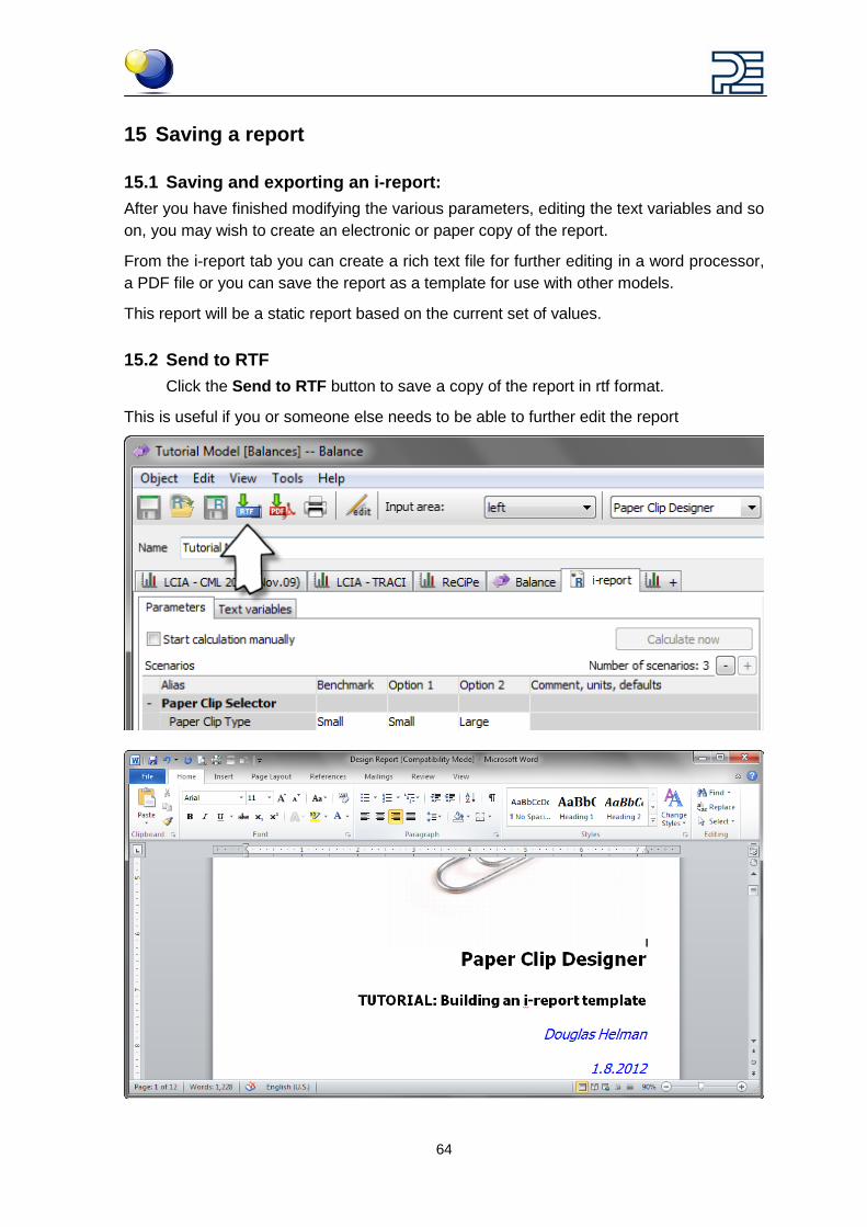
15.1 Saving and exporting an i-report: After you have finished modifying the various parameters, editing the text variables and so on, you may wish to create an electronic or paper copy of the report.
From the i-report tab you can create a rich text file for further editing in a word processor, a PDF file or you can save the report as a template for use with other models.
This report will be a static report based on the current set of values.
15.2 Send to RTF Click the Send to RTF button to save a copy of the report in rtf format.
This is useful if you or someone else needs to be able to further edit the report
65
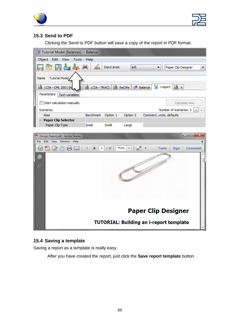
15.3 Send to PDF Clicking the Send to PDF button will save a copy of the report in PDF format.
15.4 Saving a template Saving a report as a template is really easy.
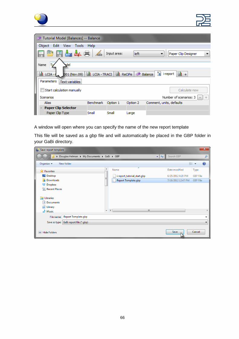
After you have created the report, just click the Save report template button
66
A window will open where you can specify the name of the new report template
This file will be saved as a gbp file and will automatically be placed in the GBP folder in your GaBi directory.
67
16 Exporting an i-report Once you have built the scenario interface and created the report template you can pre-pare the i-report for exporting as a GaBi model file using GaBi Publisher. Publisher is an add-on to GaBi that allows you to publish i-reports for use by non LCA professionals.
Here’s how:
To complete this tutorial you will need to have the GaBi Publisher add-on. If you don’t have it, you can see what it does here!
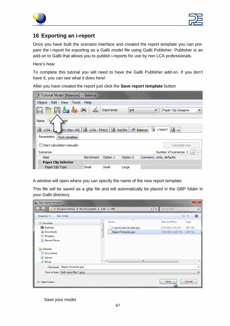
After you have created the report just click the Save report template button
A window will open where you can specify the name of the new report template
This file will be saved as a gbp file and will automatically be placed in the GBP folder in your GaBi directory.
Save your model
68
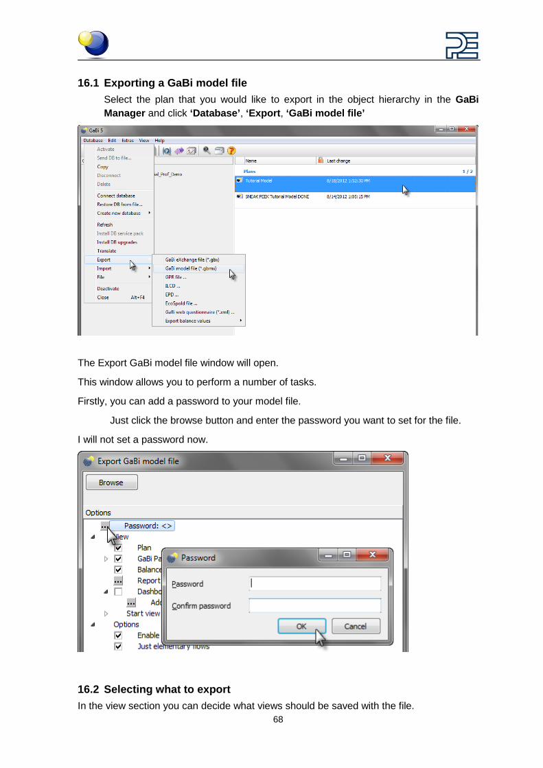
16.1 Exporting a GaBi model file Select the plan that you would like to export in the object hierarchy in the GaBi Manager and click ‘Database’, ‘Export, ‘GaBi model file’
The Export GaBi model file window will open.
This window allows you to perform a number of tasks.
Firstly, you can add a password to your model file.
Just click the browse button and enter the password you want to set for the file.
I will not set a password now.
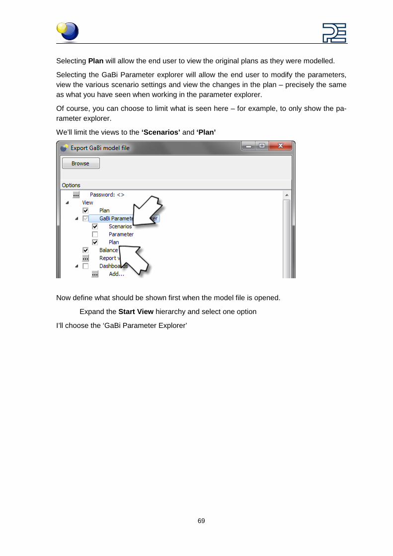
16.2 Selecting what to export In the view section you can decide what views should be saved with the file.
69
Selecting Plan will allow the end user to view the original plans as they were modelled.
Selecting the GaBi Parameter explorer will allow the end user to modify the parameters, view the various scenario settings and view the changes in the plan – precisely the same as what you have seen when working in the parameter explorer.
Of course, you can choose to limit what is seen here – for example, to only show the pa-rameter explorer.
We’ll limit the views to the ‘Scenarios’ and ‘Plan’
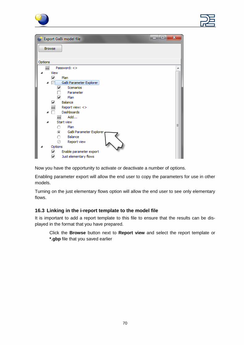
Now define what should be shown first when the model file is opened.
Expand the Start View hierarchy and select one option
I’ll choose the ‘GaBi Parameter Explorer’
70
Now you have the opportunity to activate or deactivate a number of options.
Enabling parameter export will allow the end user to copy the parameters for use in other models.
Turning on the just elementary flows option will allow the end user to see only elementary flows.
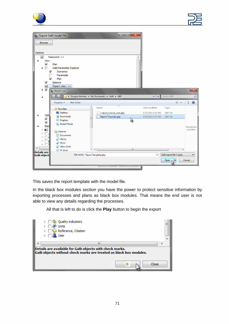
16.3 Linking in the i-report template to the model file It is important to add a report template to this file to ensure that the results can be dis-played in the format that you have prepared.
Click the Browse button next to Report view and select the report template or *.gbp file that you saved earlier
71
This saves the report template with the model file.
In the black box modules section you have the power to protect sensitive information by exporting processes and plans as black box modules. That means the end user is not able to view any details regarding the processes.
All that is left to do is click the Play button to begin the export
72
17 What next?
17.1 Using a gbmx in GaBi Envision A GaBi model file can now be sent to a GaBi Envision user who can carry out scenario analysis or even use it as a sales tool. Use GaBi Envision to generate marketing material. Product development can use it to inform decision making.
In more advanced organisations, you can upload the model file to the GaBi Envision Server for worldwide distribution to various departments and users.
With GaBi Envision the opportunities and impacts for LCA in your organisation are almost endless.
Contact your local GaBi representative to learn more or to see a live demo of GaBi’s sce-nario modelling capabilities and GaBi Envision.
http://www.gabi-software.com/contact/ We hope you found this tutorial informative and enjoyed it!