Embed Size (px)
Citation preview

FVM-1101 / FVM-1220 / FVM-1000
Web Smart Media Converter
User Manual
2
Chapter 1 Overview
1.1 Overview
FVM-1101 / FVM-1220 / FVM-1000 is remote Managed 10/100 auto-negotiation Ethernet fiber
media converter with OAM functions developed by our company. Remote devices can be managed by
fiber-connected media converters/switches (which must support IEEE802.3ah standard).
1. Offer one Ethernet port, one 100BASE-FX、100 BASE-SX/LX optical port or SFP port.
2. Support 4 kinds of OAM functions: Discover of OAM, MIB variable response, OAM Loop back,
Dying Gasp alarm.
3. Support optional LFP feature
4. Support Jumbo frame transmission
5. Support MDI/MDIX UTP cable
1.2 functional characteristics
1. Support LFP function.
2. Support Q-in-Q function, Optical port and Ethernet port can be set separately as dual Tag ports,
and can be set as ISP Tag and ISP Tag TPID at will.
3. Can query and configured the operation mode of each port on local and remote devices, including
port speed, full/half-duplex, and flow control, etc, and can display the real-time status of each port.
4. Support bandwidth-limiting function: with the step of 64kps, the bandwidth can be set between
0Mbps and 1000Mbps at will.
5.Offer MIB library files, support Open View、Snmpc, and other softwares.
6. Support link line-speed loopback, convenient for line debugging
3
Chapter 2 Technical parameters
2.1 Basic parameter
Structure Size
(H×W×D) 32mm×127mm×156mm
Optical Port SC/PC、ST/PC、FC/PC、SFP
Working temperature
(℃)
(0,45)
Storage
temperature(℃)
(-40,80)
Power dissipation(W) Typical value:5W
Relative humidity 5%~90% no condensing
4
Chapter 3 Preparation before Installing and Connection
3.1 Optical port connection
FVM-1101 / FVM-1220 / FVM-1000 supports hot plug SFP port. When one pair of optical modules is
connected, four requirements need to be fulfilled.
1. Optical wavelengths must be the same, especially for single fiber optical ports, require
transmit-receive optical wave with difference frequencies. The transmitting and receiving
operating wavelengths should match each other (for example: if TX is 1310nm, and the
opposite end RX should be 1310nm).
2. The rate of optical modules must be the same.
3. The optical powers must be matching
4. Comply with the Ethernet protocol of IEEE802.3、IEEE802.3u、IEEE802.3z、IEEE802.3x.
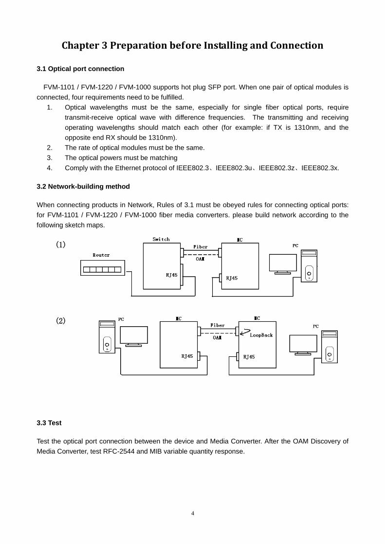
3.2 Network-building method
When connecting products in Network, Rules of 3.1 must be obeyed rules for connecting optical ports:
for FVM-1101 / FVM-1220 / FVM-1000 fiber media converters. please build network according to the
following sketch maps.
3.3 Test
Test the optical port connection between the device and Media Converter. After the OAM Discovery of
Media Converter, test RFC-2544 and MIB variable quantity response.
(1)
(2)
5
3.4 Connection between Media converter and other devices with UTP cables
Connecting the media converter and switch/router with cat UTP cables, the cables max length is to
100m.
1. Auto-negotiation of Ethernet port and MDIX/MDI function can be supported.
Fiber media converter Other devices RJ45 port
connection type
Fiber media converter Switch MDIX/MDI cable
Fiber media converter HUB MDIX/MDI cable
Fiber media converter Router MDIX/MDI cable
Fiber media converter NIC MDIX/MDI cable
3.5 Requirements for power adaptor
AC 90~264V/50/60Hz
6
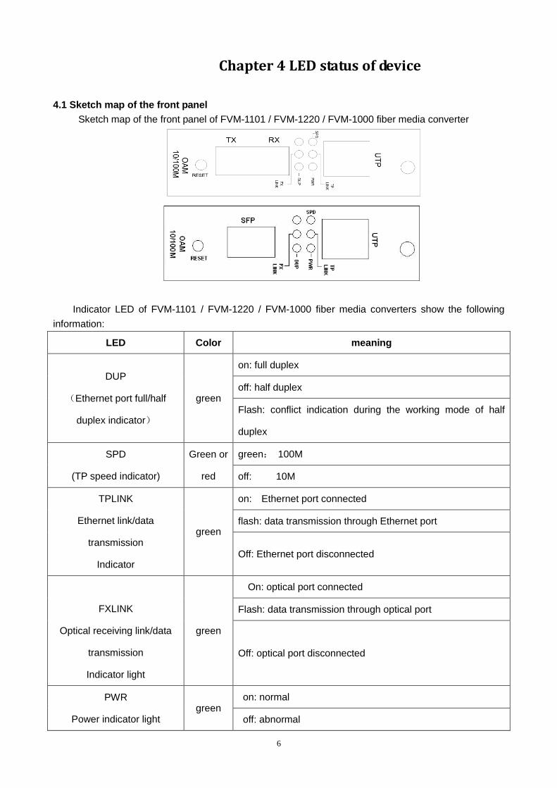
Chapter 4 LED status of device
4.1 Sketch map of the front panel
Sketch map of the front panel of FVM-1101 / FVM-1220 / FVM-1000 fiber media converter
Indicator LED of FVM-1101 / FVM-1220 / FVM-1000 fiber media converters show the following
information:
LED Color meaning
DUP
(Ethernet port full/half
duplex indicator)
green
on: full duplex
off: half duplex
Flash: conflict indication during the working mode of half
duplex
SPD
(TP speed indicator)
Green or
red
green: 100M
off: 10M
TPLINK
Ethernet link/data
transmission
Indicator
green
on: Ethernet port connected
flash: data transmission through Ethernet port
Off: Ethernet port disconnected
FXLINK
Optical receiving link/data
transmission
Indicator light
green
On: optical port connected
Flash: data transmission through optical port
Off: optical port disconnected
PWR
Power indicator light green
on: normal
off: abnormal
Chapter 5 WEB Interface
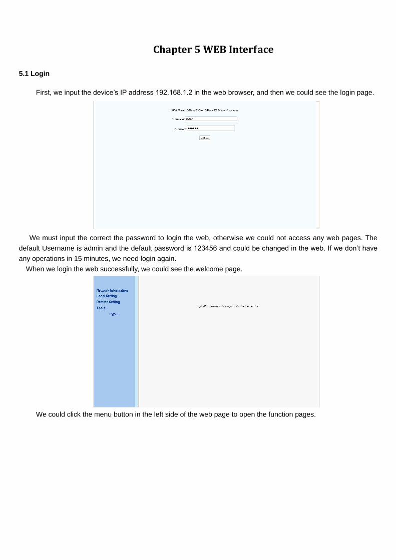
5.1 Login
First, we input the device’s IP address 192.168.1.2 in the web browser, and then we could see the login page.
We must input the correct the password to login the web, otherwise we could not access any web pages. The
default Username is admin and the default password is 123456 and could be changed in the web. If we don’t have
any operations in 15 minutes, we need login again.
When we login the web successfully, we could see the welcome page.
We could click the menu button in the left side of the web page to open the function pages.
8
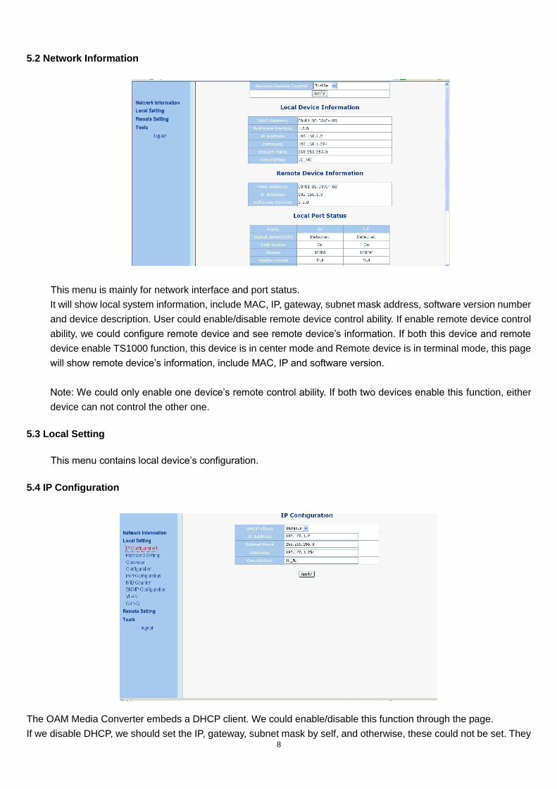
5.2 Network Information
This menu is mainly for network interface and port status.
It will show local system information, include MAC, IP, gateway, subnet mask address, software version number
and device description. User could enable/disable remote device control ability. If enable remote device control
ability, we could configure remote device and see remote device’s information. If both this device and remote
device enable TS1000 function, this device is in center mode and Remote device is in terminal mode, this page
will show remote device’s information, include MAC, IP and software version.
Note: We could only enable one device’s remote control ability. If both two devices enable this function, either
device can not control the other one.
5.3 Local Setting
This menu contains local device’s configuration.
5.4 IP Configuration
The OAM Media Converter embeds a DHCP client. We could enable/disable this function through the page.
If we disable DHCP, we should set the IP, gateway, subnet mask by self, and otherwise, these could not be set. They
9
will be provided by DHCP server. If the DHCP client is enabled, the IP address is provided by DHCP server, so user
should make sure there is a DHCP server in the net before you enable this function.
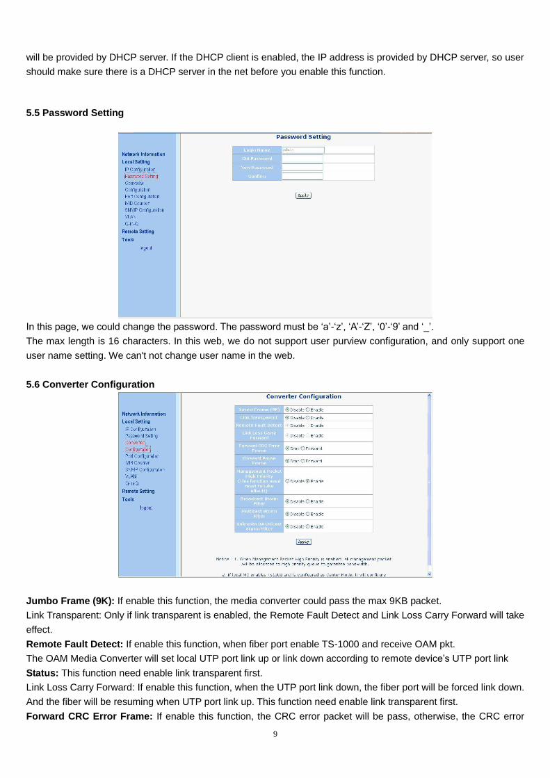
5.5 Password Setting
In this page, we could change the password. The password must be ‘a’-‘z’, ‘A’-‘Z’, ‘0’-‘9’ and ‘_’.
The max length is 16 characters. In this web, we do not support user purview configuration, and only support one
user name setting. We can't not change user name in the web.
5.6 Converter Configuration
Jumbo Frame (9K): If enable this function, the media converter could pass the max 9KB packet.
Link Transparent: Only if link transparent is enabled, the Remote Fault Detect and Link Loss Carry Forward will take
effect.
Remote Fault Detect: If enable this function, when fiber port enable TS-1000 and receive OAM pkt.
The OAM Media Converter will set local UTP port link up or link down according to remote device’s UTP port link
Status: This function need enable link transparent first.
Link Loss Carry Forward: If enable this function, when the UTP port link down, the fiber port will be forced link down.
And the fiber will be resuming when UTP port link up. This function need enable link transparent first.
Forward CRC Error Frame: If enable this function, the CRC error packet will be pass, otherwise, the CRC error
10
packets will be dropped.
Forward Pause Frame: If enable this function, The OAM Media Converter will forward pause frame and regard it as
a normal packet.
Management Packet High Priority: If enable this function, The OAM Media Converter will enable QOS.
We enable four queues, and set queue 3 as strict priority. All management packets, such as 802.3ah OAM,
SNMP packets will be in queue 3 to guarantee bandwidth.
Broadcast Storm Filter, Multicast Storm Filter, and Unknown DA unicast Storm Filter: If enable this function, when too
many broadcast/multicast/unknown DA unicast packets arrive in a period time, the packets will be dropped.
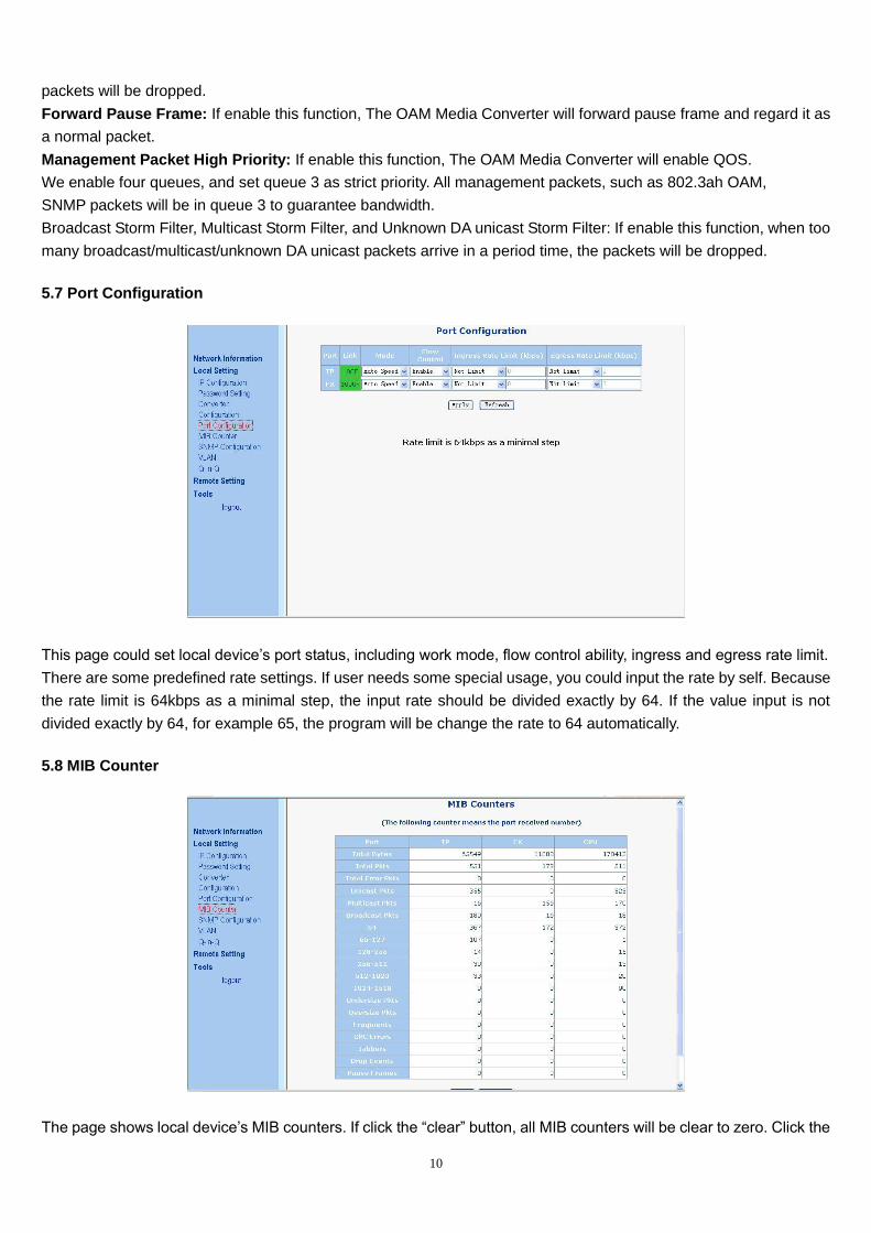
5.7 Port Configuration
This page could set local device’s port status, including work mode, flow control ability, ingress and egress rate limit.
There are some predefined rate settings. If user needs some special usage, you could input the rate by self. Because
the rate limit is 64kbps as a minimal step, the input rate should be divided exactly by 64. If the value input is not
divided exactly by 64, for example 65, the program will be change the rate to 64 automatically.
5.8 MIB Counter
The page shows local device’s MIB counters. If click the “clear” button, all MIB counters will be clear to zero. Click the
11
“refresh” button, show the current MIB counters again.
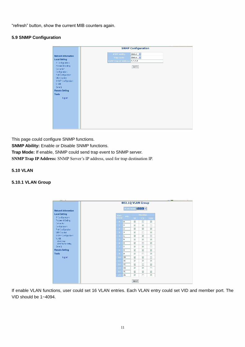
5.9 SNMP Configuration
This page could configure SNMP functions.
SNMP Ability: Enable or Disable SNMP functions.
Trap Mode: If enable, SNMP could send trap event to SNMP server.
SNMP Trap IP Address: SNMP Server’s IP address, used for trap destination IP.
5.10 VLAN
5.10.1 VLAN Group
If enable VLAN functions, user could set 16 VLAN entries. Each VLAN entry could set VID and member port. The
VID should be 1~4094.
12
5.10.2 VLAN per Port Setting
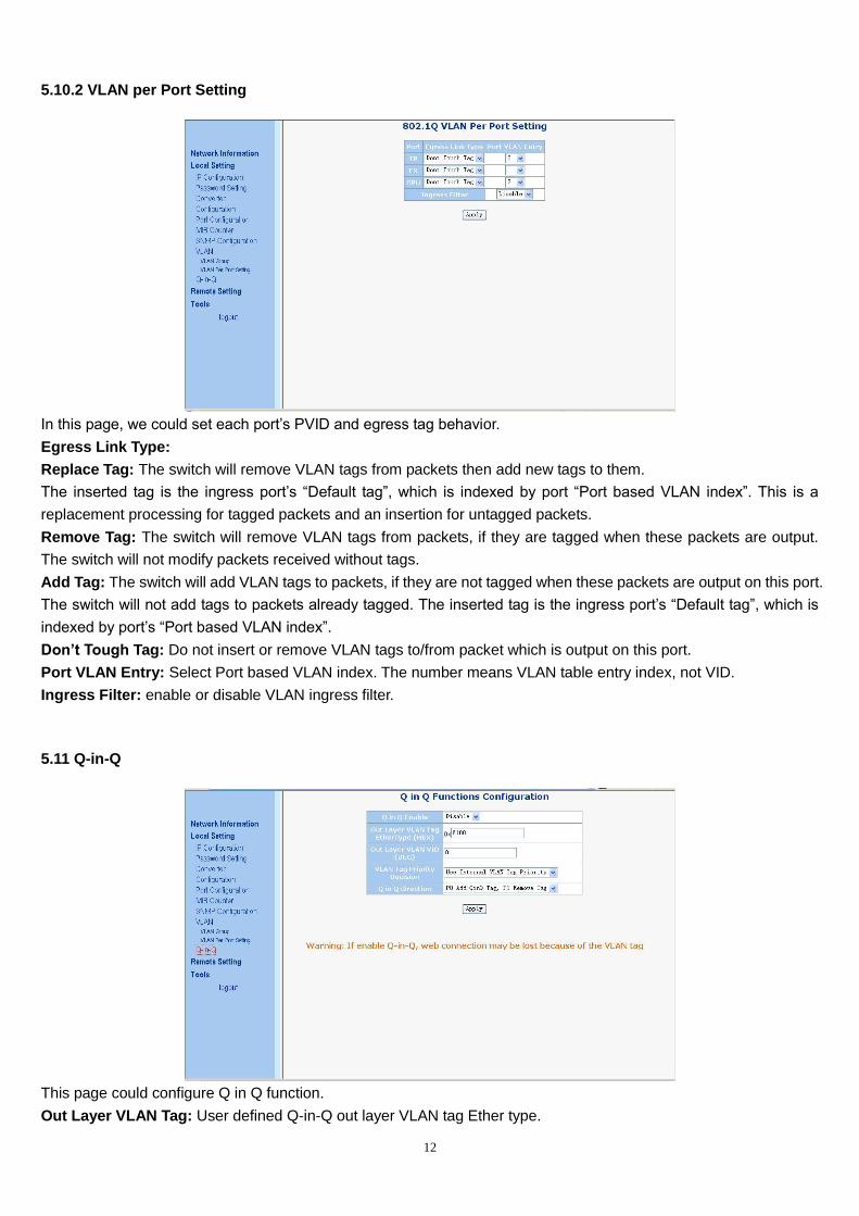
In this page, we could set each port’s PVID and egress tag behavior.
Egress Link Type:
Replace Tag: The switch will remove VLAN tags from packets then add new tags to them.
The inserted tag is the ingress port’s “Default tag”, which is indexed by port “Port based VLAN index”. This is a
replacement processing for tagged packets and an insertion for untagged packets.
Remove Tag: The switch will remove VLAN tags from packets, if they are tagged when these packets are output.
The switch will not modify packets received without tags.
Add Tag: The switch will add VLAN tags to packets, if they are not tagged when these packets are output on this port.
The switch will not add tags to packets already tagged. The inserted tag is the ingress port’s “Default tag”, which is
indexed by port’s “Port based VLAN index”.
Don’t Tough Tag: Do not insert or remove VLAN tags to/from packet which is output on this port.
Port VLAN Entry: Select Port based VLAN index. The number means VLAN table entry index, not VID.
Ingress Filter: enable or disable VLAN ingress filter.
5.11 Q-in-Q
This page could configure Q in Q function.
Out Layer VLAN Tag: User defined Q-in-Q out layer VLAN tag Ether type.
13
Out Layer VLAN VID: User defined Q-in-Q out layer VLAN tag VID
VLAN Tag Priority Decision: Decide out layer VLAN Tag’s priority, use internal VLAN tag’s priority or 802.1p
remarking decision priority.
Q in Q direction: Select Q in Q direction, which port adds tag, and which port removes tag.
5.12 Remote Setting
5.12.1 TS1000 Functions
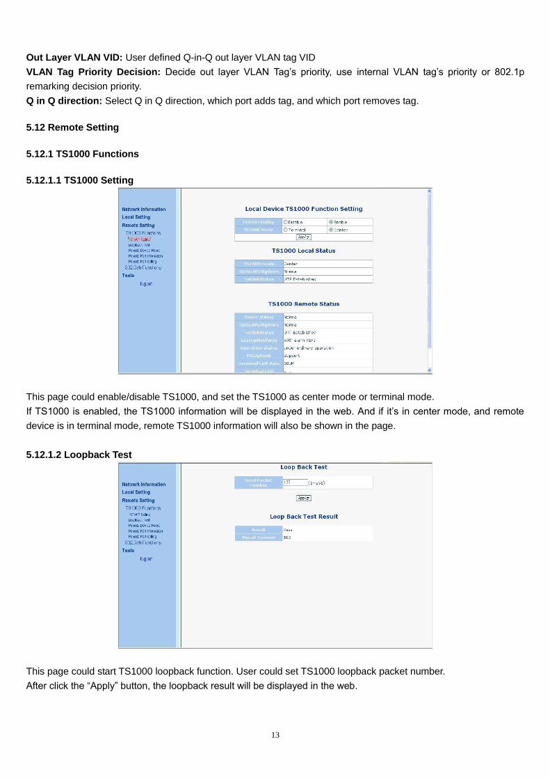
5.12.1.1 TS1000 Setting
This page could enable/disable TS1000, and set the TS1000 as center mode or terminal mode.
If TS1000 is enabled, the TS1000 information will be displayed in the web. And if it’s in center mode, and remote
device is in terminal mode, remote TS1000 information will also be shown in the page.
5.12.1.2 Loopback Test
This page could start TS1000 loopback function. User could set TS1000 loopback packet number.
After click the “Apply” button, the loopback result will be displayed in the web.
14
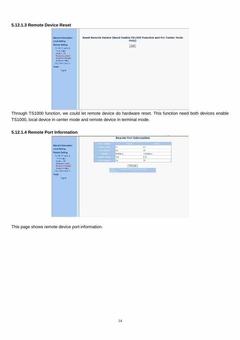
5.12.1.3 Remote Device Reset
Through TS1000 function, we could let remote device do hardware reset. This function need both devices enable
TS1000, local device in center mode and remote device in terminal mode.
5.12.1.4 Remote Port Information
This page shows remote device port information.
15
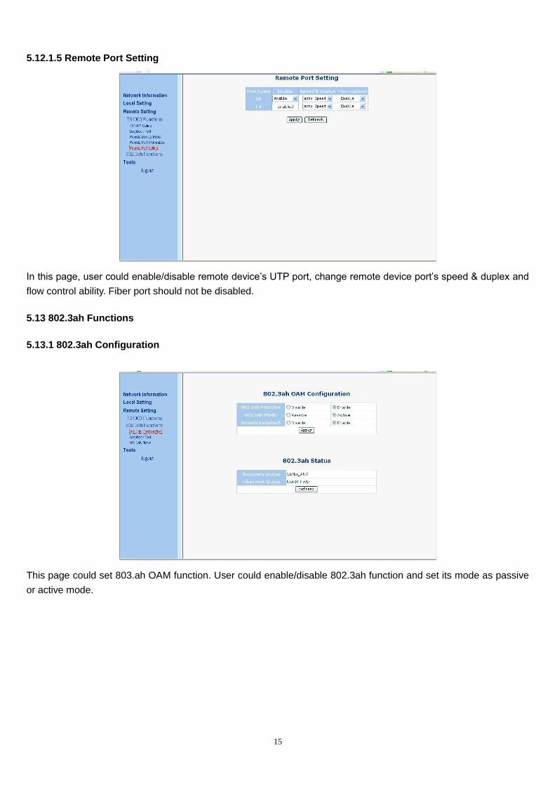
5.12.1.5 Remote Port Setting
In this page, user could enable/disable remote device’s UTP port, change remote device port’s speed & duplex and
flow control ability. Fiber port should not be disabled.
5.13 802.3ah Functions
5.13.1 802.3ah Configuration
This page could set 803.ah OAM function. User could enable/disable 802.3ah function and set its mode as passive
or active mode.
16
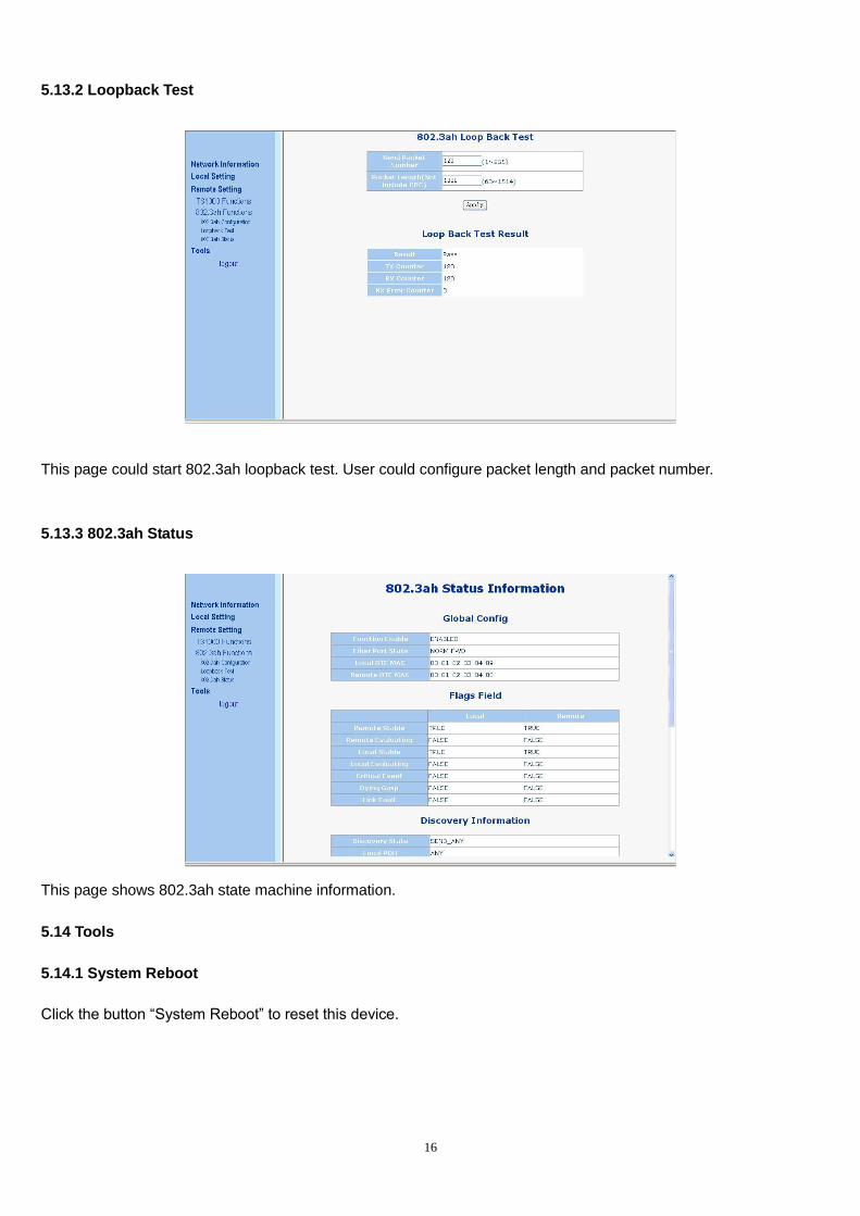
5.13.2 Loopback Test
This page could start 802.3ah loopback test. User could configure packet length and packet number.
5.13.3 802.3ah Status
This page shows 802.3ah state machine information.
5.14 Tools
5.14.1 System Reboot
Click the button “System Reboot” to reset this device.
17
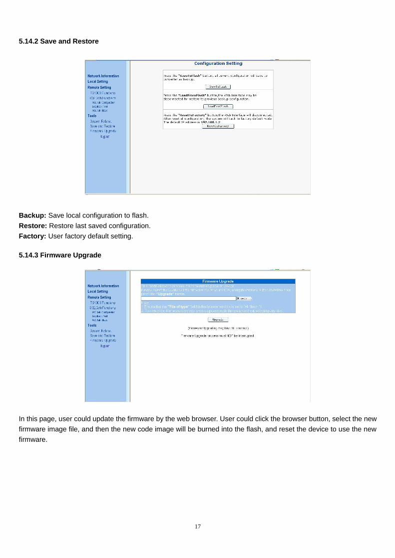
5.14.2 Save and Restore
Backup: Save local configuration to flash.
Restore: Restore last saved configuration.
Factory: User factory default setting.
5.14.3 Firmware Upgrade
In this page, user could update the firmware by the web browser. User could click the browser button, select the new
firmware image file, and then the new code image will be burned into the flash, and reset the device to use the new
firmware.
18
Chapter 6 OAM (IEEE802.3ah) function
6.1 Overview
FVM-1101 / FVM-1220 / FVM-1000 supports four kinds of standard OAM functions: Discovery of OAM, MIB
variable response, OAM loopback, Dying Gasp alarm
6.2 Discovery of OAM
When FVM-1101 / FVM-1220 / FVM-1000 is connected with the initiative device that can support 803.3ah, FVM-1101
/ FVM-1220 / FVM-1000 will wait for OAM initiative device to initiate OAM discovery Process. After OAM is
discovered, other OAM functions can be realized.
6.3 MIB Variable response
FVM-1101 / FVM-1220 / FVM-1000 supports MIB variable response processed by switch chips, which is a
subset of standard MIB. FVM-1101 / FVM-1220 / FVM-1000 responses only to requests of the initiative device, if
the requesting object is MIB information that FVM-1101 / FVM-1220 / FVM-1000 doesn’t have, MIB variable
response will return a null instruction.
6.4 OAM Loopback
FVM-1101 / FVM-1220 / FVM-1000 supports Loopback initiated by OAM initiative device. During the process of
loopback, the Ethernet port operation of FVM-1101 / FVM-1220 / FVM-1000 will be disconnected. And after the
loopback, it will be reconnected.
6.5 Dying Gasp alarm
When FVM-1101 / FVM-1220 / FVM-1000 is power down, Dying Gasp alarm will be sent to OAM initiative
device.