Embed Size (px)
Citation preview
COMPDYN 2019
7th ECCOMAS Thematic Conference on
Computational Methods in Structural Dynamics and Earthquake Engineering
M. Papadrakakis, M. Fragiadakis (eds.)
Crete, Greece, 24–26 June 2019
FULL SCALE TESTS OF THE BASE-ISOLATION SYSTEM FOR AN
EMERGENCY HOSPITAL
M.F. Ferrotto1, L. Cavaleri
1, F. Di Trapani
2 and P. Castaldo
2,
1 Università degli Studi Palermo, Department of Engineering,Viale delle Scienze 90128 Palermo, Italy
e-mail:{liborio.cavaleri, marcofilippo.ferrotto}@unipa.it
2 Politecnico di Torino, Department of Structural, Geotechnical and Building Engineering
Corso Duca degli Abbruzzi 10129 Torino, Italy
e-mail: {paolo.castaldo, fabio.ditrapani}@polito.it
Abstract
The paper presents the results of some full-scale tests regarding the base-isolation system of
the emergency room building of the polyclinic hospital in Palermo (Italy). This building has
been recently realized and its base isolation system is characterized by double friction pendu-
lum isolators. Static lateral pushing tests were aimed at identifying fundamental mechanical
properties of the whole isolation level (e.g. friction forces and stiffness) in order to verify the
agreement with the design hypotheses. Further dynamic tests provided different displace-
ments of the isolated base followed by the instantaneous release (snap-back tests), in order to
verify the effectiveness, the mechanical parameter in dynamics and re-centering capacity of
the isolation system. The design of both the types of test and the respective results and inter-
pretations are illustrated in the paper highlighting a number of issues arising when arranging
such kind of investigations on full scale buildings.
Keywords: Friction pendulum bearing, seismic isolation, snap-back test, friction, in-situ test-
ing, full-scale experimental tests.

M.F. Ferrotto, L. Cavaleri, F. Di Trapani, P. Castaldo,
1 INTRODUCTION
Friction pendulum isolators (FPIs) have been widely used in the last decades for several
applications for the seismic protection of strategic structures such as bridges, emergency
buildings, hospitals, etc, in high-risk seismic areas and sometimes for residential buildings
[1]. The advantages in the adoption of this kind of seismic isolation systems is due to the high
dissipative capacity, the possibility of obtaining a mass independent period of the superstruc-
ture and, the durability; the re-centering capacity is entrusted to the geometric configuration
of the isolator curved sliding surfaces [2-3].
Despite the static and dynamic behavior of these systems has been deepen analyzed in the
recent years also by the experimental point of view [4-8], very few studies about the in-situ
behavior of structures equipped with FPIs are available nowadays.
The actual dynamic behavior of base-isolated structures can be investigated by quick re-
lease tests, more generally called snap back tests. This approach is well suited because the
movement of the structure requires a quantity of energy obtainable without excessive difficul-
ties, allowing to observe the dynamic behavior according to the design displacement values.
In detail, the structure is moved (pushed) to a given value of displacement – e.g. correspond-
ing to a certain Limit State – and sudden released causing free vibrations. In this way, the
performances of the isolation devices can be observed, comparing the in-situ behavior with
that of the design provisions.
In the last decades, a number of field tests on base-isolated structures were successfully
carried out [9-16]. Among the most relevant available studies, Braga and Laterza [11] per-
formed a series of dynamic snap-back tests on a residence building mounted on a hybrid iso-
lation system, having sliding bearings for isolation and steel rubber bearings to have a re-
centering force. The in-situ dynamic behavior of the structure was compared with experi-
mental shear tests on the isolator devices.
He et al. [15] carried out ambient vibration tests, free attenuation vibration tests, sinusoidal
vibration tests and displacement controlled earthquake simulation tests on a laminated rubber
bearings (LNR) and lead rubber bearing (LRB) base-isolated 15-story steel structure in Kun-
ming city, China.
Gesualdi et al. [16] presented the results of in-situ release tests carried out on a rubber
bearing and a flat sliding bearing of a 3-storey base-isolated reinforced concrete frame build-
ing located in the city of Augusta, Sicily. The authors used the results of ambient vibration
and release tests to calibrate numerical models, performing reliable dynamic analyses and
comparing the results with that of the design seismic performances.
What above described highlights the role attributed to seismic isolation systems that, when
possible, are preferred to seismic resisting structures exploiting the ductility capacity or the
contribution of infills [17-20] or to an improvement of strength and ductility by means of tra-
ditional retrofitting systems [21-23], or to passive dissipation devices [24-26].
In this paper, a series of quasi-static and dynamic snap-back tests carried out on the base-
isolated new emergency room building of the university polyclinic hospital of Palermo are
described and discussed. The isolated structure was realized on double curved friction pendu-
lum isolators.
Static lateral pushing tests were aimed at identifying the fundamental mechanical proper-
ties of the whole isolation system (e.g. friction forces and stiffness) in order to verify the
agreement with the design hypotheses. Further dynamic tests consisted of imposing different
displacements at the isolated level and then instantaneously releasing, in order to verify its
effectiveness, to measure its dynamical properties and to observe the re-centering capacity.
P. Castaldo, L. Cavaleri, F. Di Trapani, M. Ferrotto
The design of the field testing, comprising the thrust mechanical device and the reaction
wall is described along the paper followed by the description of the in-situ testing and its main
results.
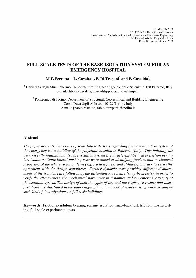
2 DESCRIPTION OF THE STRUCTURE
The building has a non-regular plan with a 5-sided polygonal shape. It has a length of 46.3
m and a maximum width of 21.3 m. The isolated superstructure has 3 floors with an inter-
storey height of about 4 meters. The superstructure is steel framed, characterized by 41 col-
umns made of HEB 300 steel profiles in agreement to the classification of Eurocode 3. The
rigid base on the isolators is a reinforced concrete plate as for the slabs of the superstructure.
The substructure is characterized by reinforced concrete columns on a slab foundation. Fig.1
shows a vertical section of the building.
Figure 1: Vertical section of the building structure
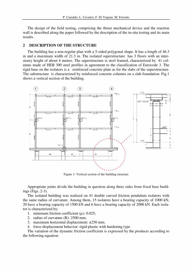
Appropriate joints divide the building in question along three sides from fixed base build-
ings (Figs. 2-3).
The isolated building was realized on 41 double curved friction pendulum isolators with
the same radius of curvature. Among them, 15 isolators have a bearing capacity of 1000 kN,
20 have a bearing capacity of 1500 kN and 6 have a bearing capacity of 2000 kN. Each isola-
tor is characterized by:
1. minimum friction coefficient (µ): 0.025;
2. radius of curvature (R): 2500 mm;
3. maximum horizontal displacement: ±250 mm;
4. force-displacement behavior: rigid-plastic with hardening type
The variation of the dynamic friction coefficient is expressed by the producer according to
the following equation:
M.F. Ferrotto, L. Cavaleri, F. Di Trapani, P. Castaldo,
834.0
5.2
−
=
Ed
Sd
N
Nµ (1)
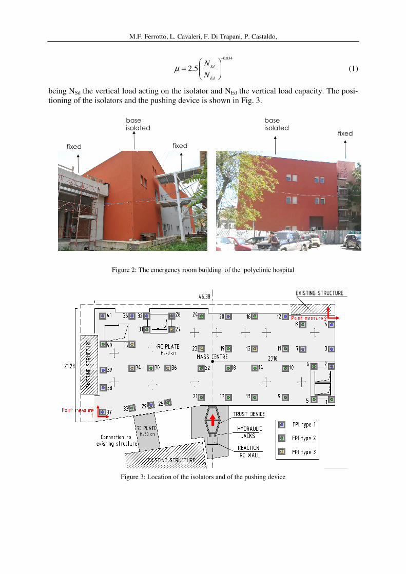
being NSd the vertical load acting on the isolator and NEd the vertical load capacity. The posi-
tioning of the isolators and the pushing device is shown in Fig. 3.
fixed fixed
fixed
base
isolated
base
isolated
Figure 2: The emergency room building of the polyclinic hospital
Figure 3: Location of the isolators and of the pushing device
P. Castaldo, L. Cavaleri, F. Di Trapani, M. Ferrotto
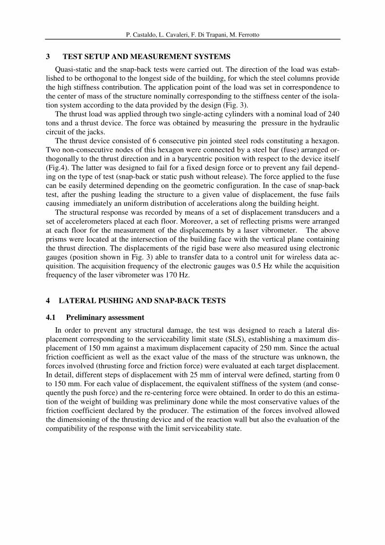
3 TEST SETUP AND MEASUREMENT SYSTEMS
Quasi-static and the snap-back tests were carried out. The direction of the load was estab-
lished to be orthogonal to the longest side of the building, for which the steel columns provide
the high stiffness contribution. The application point of the load was set in correspondence to
the center of mass of the structure nominally corresponding to the stiffness center of the isola-
tion system according to the data provided by the design (Fig. 3).
The thrust load was applied through two single-acting cylinders with a nominal load of 240
tons and a thrust device. The force was obtained by measuring the pressure in the hydraulic
circuit of the jacks.
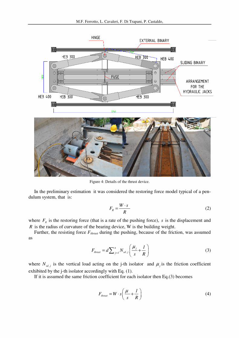
The thrust device consisted of 6 consecutive pin jointed steel rods constituting a hexagon.
Two non-consecutive nodes of this hexagon were connected by a steel bar (fuse) arranged or-
thogonally to the thrust direction and in a barycentric position with respect to the device itself
(Fig.4). The latter was designed to fail for a fixed design force or to prevent any fail depend-
ing on the type of test (snap-back or static push without release). The force applied to the fuse
can be easily determined depending on the geometric configuration. In the case of snap-back
test, after the pushing leading the structure to a given value of displacement, the fuse fails
causing immediately an uniform distribution of accelerations along the building height.
The structural response was recorded by means of a set of displacement transducers and a
set of accelerometers placed at each floor. Moreover, a set of reflecting prisms were arranged
at each floor for the measurement of the displacements by a laser vibrometer. The above
prisms were located at the intersection of the building face with the vertical plane containing
the thrust direction. The displacements of the rigid base were also measured using electronic
gauges (position shown in Fig. 3) able to transfer data to a control unit for wireless data ac-
quisition. The acquisition frequency of the electronic gauges was 0.5 Hz while the acquisition
frequency of the laser vibrometer was 170 Hz.
4 LATERAL PUSHING AND SNAP-BACK TESTS
4.1 Preliminary assessment
In order to prevent any structural damage, the test was designed to reach a lateral dis-
placement corresponding to the serviceability limit state (SLS), establishing a maximum dis-
placement of 150 mm against a maximum displacement capacity of 250 mm. Since the actual
friction coefficient as well as the exact value of the mass of the structure was unknown, the
forces involved (thrusting force and friction force) were evaluated at each target displacement.
In detail, different steps of displacement with 25 mm of interval were defined, starting from 0
to 150 mm. For each value of displacement, the equivalent stiffness of the system (and conse-
quently the push force) and the re-centering force were obtained. In order to do this an estima-
tion of the weight of building was preliminary done while the most conservative values of the
friction coefficient declared by the producer. The estimation of the forces involved allowed
the dimensioning of the thrusting device and of the reaction wall but also the evaluation of the
compatibility of the response with the limit serviceability state.
M.F. Ferrotto, L. Cavaleri, F. Di Trapani, P. Castaldo,
Figure 4: Details of the thrust device.
In the preliminary estimation it was considered the restoring force model typical of a pen-
dulum system, that is:
R
W sF
R
⋅= (2)
where R
F is the restoring force (that is a rate of the pushing force), s is the displacement and
R is the radius of curvature of the bearing device, W is the building weight.
Further, the resisting force Fthrust during the pushing, because of the friction, was assumed
as
n j
thrust sd , jj 1
1F d N
s R
µ
=
= +
(3)
where sd , j
N is the vertical load acting on the j-th isolator and j
µ is the friction coefficient
exhibited by the j-th isolator accordingly with Eq. (1).
If it is assumed the same friction coefficient for each isolator then Eq.(3) becomes
thrust
1F W s
s R
µ = ⋅ +
(4)
P. Castaldo, L. Cavaleri, F. Di Trapani, M. Ferrotto
Also, the instantaneous stiffness becomes
inst
1K W
s R
µ = +
(5)
From Eq. 5 it derives the coincidence of the center of stiffness and the center of mass. The re-
centering force (rec
F ), that is a pull force, because of a uniform friction, can be obtained as:
rec
sF W
Rµ
= −
(64)
Assumed a first attempt value of the weight of the structure of 25000 kN, it was possible to
evaluate the load acting on each single bearing device and the corresponding friction coeffi-
cient. Then, an average value of the friction coefficient was calculated and preliminary analyt-
ical evaluation of the thrust loads and the re-centering forces was made to estimate the
expected level of forces to be achieved during the field testing.
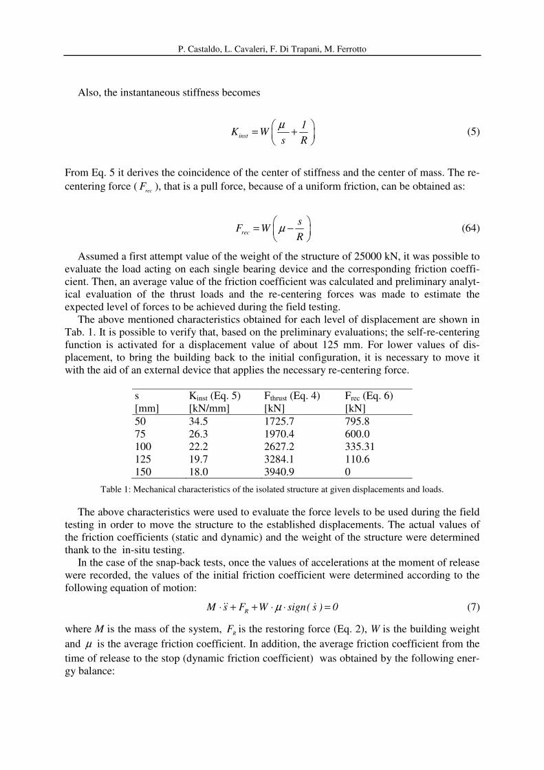
The above mentioned characteristics obtained for each level of displacement are shown in
Tab. 1. It is possible to verify that, based on the preliminary evaluations; the self-re-centering
function is activated for a displacement value of about 125 mm. For lower values of dis-
placement, to bring the building back to the initial configuration, it is necessary to move it
with the aid of an external device that applies the necessary re-centering force.
s
[mm]
Kinst (Eq. 5)
[kN/mm]
Fthrust (Eq. 4)
[kN]
Frec (Eq. 6)
[kN]
50 34.5 1725.7 795.8
75 26.3 1970.4 600.0
100 22.2 2627.2 335.31
125 19.7 3284.1 110.6
150 18.0 3940.9 0
Table 1: Mechanical characteristics of the isolated structure at given displacements and loads.
The above characteristics were used to evaluate the force levels to be used during the field
testing in order to move the structure to the established displacements. The actual values of
the friction coefficients (static and dynamic) and the weight of the structure were determined
thank to the in-situ testing.
In the case of the snap-back tests, once the values of accelerations at the moment of release
were recorded, the values of the initial friction coefficient were determined according to the
following equation of motion:
R
M s F W sign( s ) 0µ⋅ + + ⋅ ⋅ =&& & (7)
where M is the mass of the system, R
F is the restoring force (Eq. 2), W is the building weight
and µ is the average friction coefficient. In addition, the average friction coefficient from the
time of release to the stop (dynamic friction coefficient) was obtained by the following ener-
gy balance:
M.F. Ferrotto, L. Cavaleri, F. Di Trapani, P. Castaldo,
pfdpi
EEE += (8a)
22f0
pi d i pf
W sW sE 0.5 ; E W s ; E 0.5
R Rµ
⋅⋅= = ⋅ ⋅ = (8b)
being pi
E the initial potential energy, d
E the dissipated energy by friction and pf
E the final
potential energy, depending on the initial displacement 0
s (at the moment of release) and on
the final residual displacement f
s .
4.2 Results: quasi-static tests
Two quasi-static lateral pushing tests were carried out to evaluate:
1) the actual weight of the superstructure;
2) the mechanical characteristics of the base isolation system (static friction coefficient);
3) the actual thrusting force to be applied for the reaching of the target displacement in the
snap-back test ;
4) the strength of the fuse to be chosen basing on the actual thrusting force.
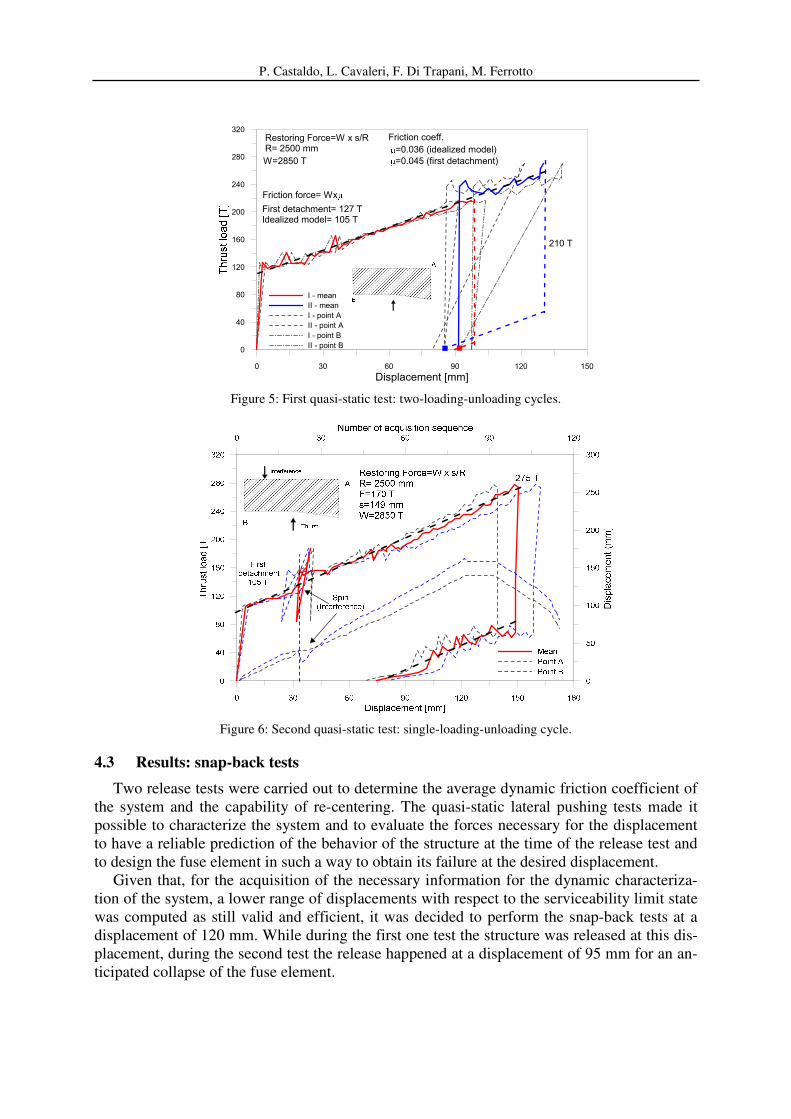
During the first test the structure was pushed up to an average displacement (mean in the
direction of the thrust of the displacements measured at points A and B of Fig. 5 – the same
points are called 1 and 2 in Fig.3) of about 97.6 mm, after which a slow discharge was carried
out and the structure moved back showing a residual displacement of approximately 92 mm.
The thrust was subsequently increased again until a mean displacement of 130.12 mm was
achieved. After the unloading the residual displacement was 85 mm.
Fig. 5 shows both the displacements of the measurement points A and B and the average
displacement. The average friction coefficient of first detachment and the average friction co-
efficient after the first detachment are reported in Fig. 5. The first is calculated by referring to
the effective force of first detachment while the second is calculated based on the idealized
model (Eq.4) fitting the experimental results. It is possible to note that, during the pushing,
the building exhibited a clockwise rotation. This effect was probably caused by a different
ratio between capacity and demand in terms of vertical load on each isolator which deter-
mined different coefficient of friction for each isolator (Eq.(1)). As a consequence, the stiff-
ness center resulted in a position different from that of the mass center where the thrusting
load was applied.
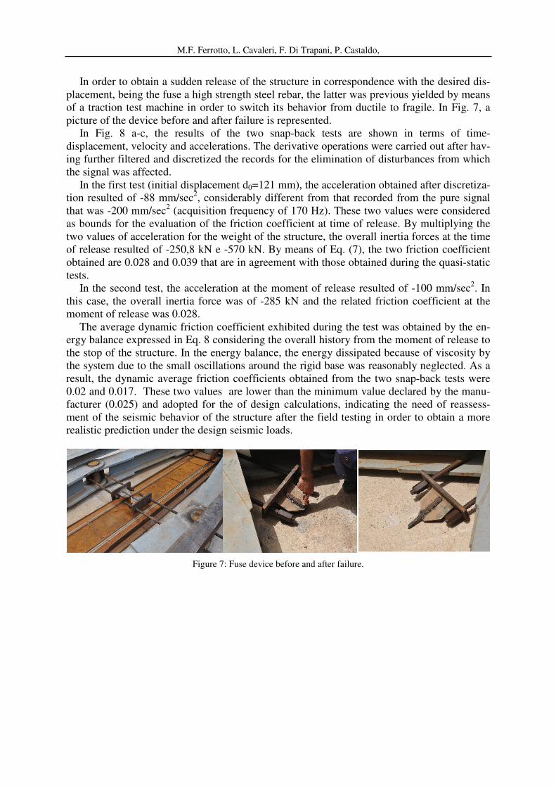
After the re-centering, in the second test the structure was pushed up to a mean displace-
ment of 150.7 mm by a single pushing cycle (Fig. 6). During the lateral pushing test, after
reaching a displacement of about 30 mm, the structure exhibited a rotation due to an interfer-
ence. A careful inspection showed the presence of a hydraulic jack used for the re-centering
operations left in place. After the removing, the structure was repositioned to the right config-
uration, continuing the lateral pushing test. It can be observed that the friction force at the first
detachment, as expected, is the typical one exhibited by friction systems that have already ex-
perienced previous first detachment. Therefore, an initial resisting forces lower than that de-
tected in the first test was exibited. Specifically, the force coincides with that obtained from
the idealized model derived from the first test.
In both tests, the weight of the structure resulted by the using of Eq.(2) where, for FR, the
difference between the forces observed in the final and initial points of the linear ascending
branch of response has been used. Consequently, a weight of 28500 kN (slightly higher than
25000 kN previously assumed) was obtained. Then, the friction coefficient at the first de-
tachment (evaluated considering that the friction force Ff assumes the expression Ff=Wxµ)
resulted of 0.045 and the static friction coefficient during the test resulted meanly 0.036.
P. Castaldo, L. Cavaleri, F. Di Trapani, M. Ferrotto
0 30 60 90 120 150
Displacement [mm]
0
40
80
120
160
200
240
280
320
I - mean
II - mean
I - point A
II - point A
I - point B
II - point B
210 T
Restoring Force=W x s/RR= 2500 mm
W=2850 T
=0.036 (idealized model)
=0.045 (first detachment)
First detachment= 127 TIdealized model= 105 T
Friction force= Wx
Friction coeff.
Figure 5: First quasi-static test: two-loading-unloading cycles.
Figure 6: Second quasi-static test: single-loading-unloading cycle.
4.3 Results: snap-back tests
Two release tests were carried out to determine the average dynamic friction coefficient of
the system and the capability of re-centering. The quasi-static lateral pushing tests made it
possible to characterize the system and to evaluate the forces necessary for the displacement
to have a reliable prediction of the behavior of the structure at the time of the release test and
to design the fuse element in such a way to obtain its failure at the desired displacement.
Given that, for the acquisition of the necessary information for the dynamic characteriza-
tion of the system, a lower range of displacements with respect to the serviceability limit state
was computed as still valid and efficient, it was decided to perform the snap-back tests at a
displacement of 120 mm. While during the first one test the structure was released at this dis-
placement, during the second test the release happened at a displacement of 95 mm for an an-
ticipated collapse of the fuse element.
M.F. Ferrotto, L. Cavaleri, F. Di Trapani, P. Castaldo,
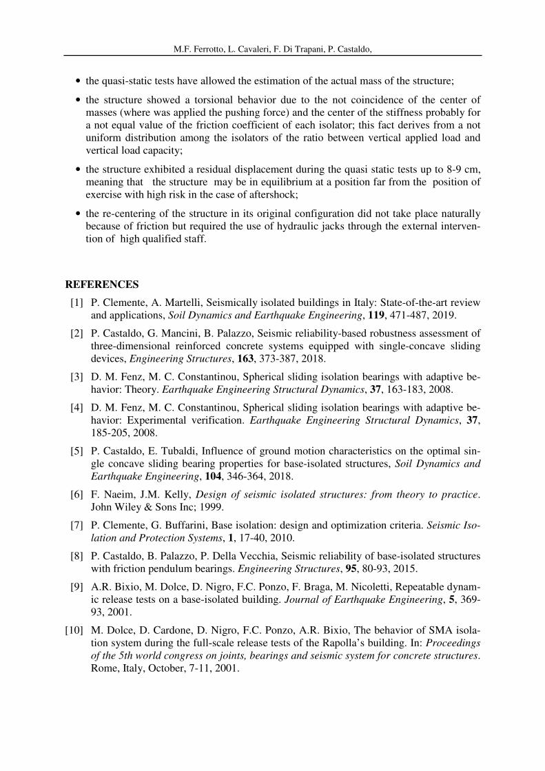
In order to obtain a sudden release of the structure in correspondence with the desired dis-
placement, being the fuse a high strength steel rebar, the latter was previous yielded by means
of a traction test machine in order to switch its behavior from ductile to fragile. In Fig. 7, a
picture of the device before and after failure is represented.
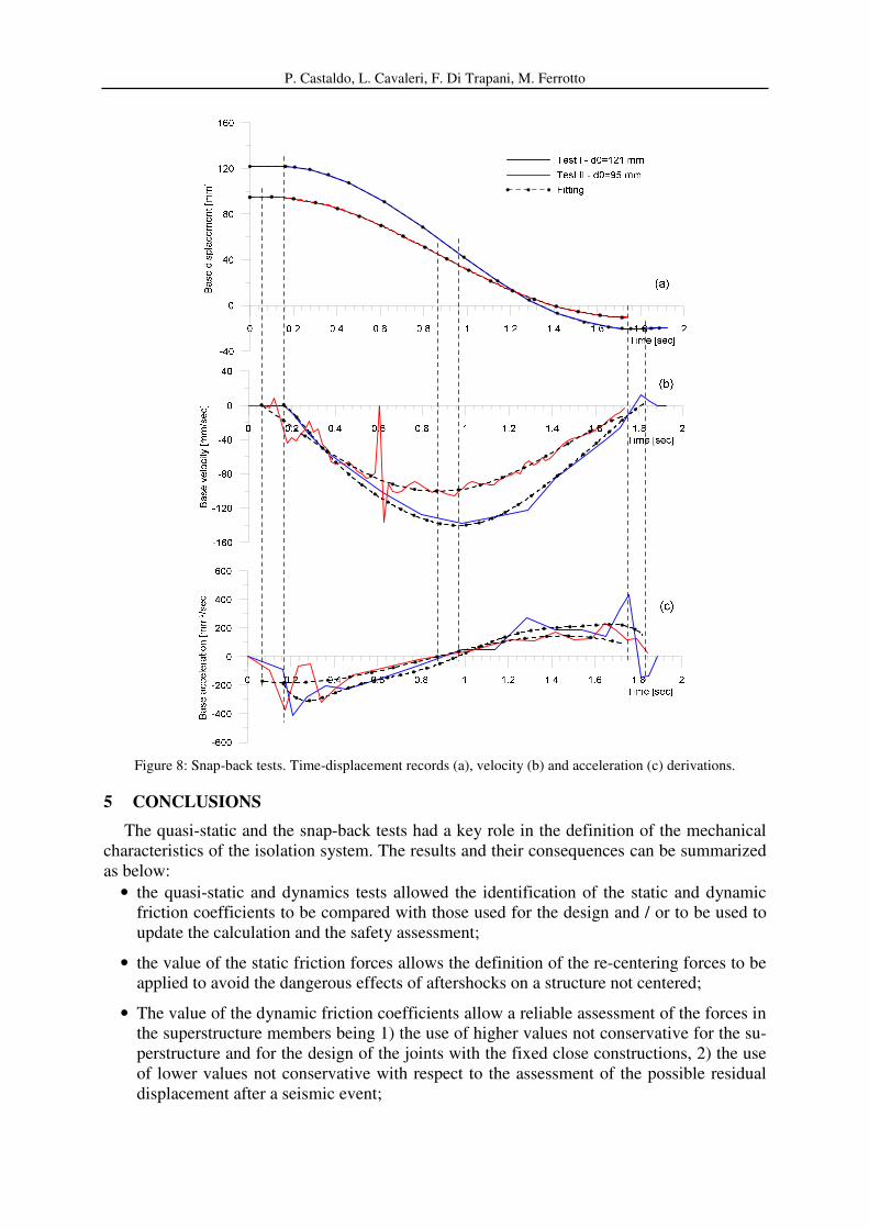
In Fig. 8 a-c, the results of the two snap-back tests are shown in terms of time-
displacement, velocity and accelerations. The derivative operations were carried out after hav-
ing further filtered and discretized the records for the elimination of disturbances from which
the signal was affected.
In the first test (initial displacement d0=121 mm), the acceleration obtained after discretiza-
tion resulted of -88 mm/sec2, considerably different from that recorded from the pure signal
that was -200 mm/sec2 (acquisition frequency of 170 Hz). These two values were considered
as bounds for the evaluation of the friction coefficient at time of release. By multiplying the
two values of acceleration for the weight of the structure, the overall inertia forces at the time
of release resulted of -250,8 kN e -570 kN. By means of Eq. (7), the two friction coefficient
obtained are 0.028 and 0.039 that are in agreement with those obtained during the quasi-static
tests.
In the second test, the acceleration at the moment of release resulted of -100 mm/sec2. In
this case, the overall inertia force was of -285 kN and the related friction coefficient at the
moment of release was 0.028.
The average dynamic friction coefficient exhibited during the test was obtained by the en-
ergy balance expressed in Eq. 8 considering the overall history from the moment of release to
the stop of the structure. In the energy balance, the energy dissipated because of viscosity by
the system due to the small oscillations around the rigid base was reasonably neglected. As a
result, the dynamic average friction coefficients obtained from the two snap-back tests were
0.02 and 0.017. These two values are lower than the minimum value declared by the manu-
facturer (0.025) and adopted for the of design calculations, indicating the need of reassess-
ment of the seismic behavior of the structure after the field testing in order to obtain a more
realistic prediction under the design seismic loads.
Figure 7: Fuse device before and after failure.
P. Castaldo, L. Cavaleri, F. Di Trapani, M. Ferrotto
Figure 8: Snap-back tests. Time-displacement records (a), velocity (b) and acceleration (c) derivations.
5 CONCLUSIONS
The quasi-static and the snap-back tests had a key role in the definition of the mechanical
characteristics of the isolation system. The results and their consequences can be summarized
as below:
• the quasi-static and dynamics tests allowed the identification of the static and dynamic
friction coefficients to be compared with those used for the design and / or to be used to
update the calculation and the safety assessment;
• the value of the static friction forces allows the definition of the re-centering forces to be
applied to avoid the dangerous effects of aftershocks on a structure not centered;
• The value of the dynamic friction coefficients allow a reliable assessment of the forces in
the superstructure members being 1) the use of higher values not conservative for the su-
perstructure and for the design of the joints with the fixed close constructions, 2) the use
of lower values not conservative with respect to the assessment of the possible residual
displacement after a seismic event;
M.F. Ferrotto, L. Cavaleri, F. Di Trapani, P. Castaldo,
• the quasi-static tests have allowed the estimation of the actual mass of the structure;
• the structure showed a torsional behavior due to the not coincidence of the center of
masses (where was applied the pushing force) and the center of the stiffness probably for
a not equal value of the friction coefficient of each isolator; this fact derives from a not
uniform distribution among the isolators of the ratio between vertical applied load and
vertical load capacity;
• the structure exhibited a residual displacement during the quasi static tests up to 8-9 cm,
meaning that the structure may be in equilibrium at a position far from the position of
exercise with high risk in the case of aftershock;
• the re-centering of the structure in its original configuration did not take place naturally
because of friction but required the use of hydraulic jacks through the external interven-
tion of high qualified staff.
REFERENCES
[1] P. Clemente, A. Martelli, Seismically isolated buildings in Italy: State-of-the-art review
and applications, Soil Dynamics and Earthquake Engineering, 119, 471-487, 2019.
[2] P. Castaldo, G. Mancini, B. Palazzo, Seismic reliability-based robustness assessment of
three-dimensional reinforced concrete systems equipped with single-concave sliding
devices, Engineering Structures, 163, 373-387, 2018.
[3] D. M. Fenz, M. C. Constantinou, Spherical sliding isolation bearings with adaptive be-
havior: Theory. Earthquake Engineering Structural Dynamics, 37, 163-183, 2008.
[4] D. M. Fenz, M. C. Constantinou, Spherical sliding isolation bearings with adaptive be-
havior: Experimental verification. Earthquake Engineering Structural Dynamics, 37,
185-205, 2008.
[5] P. Castaldo, E. Tubaldi, Influence of ground motion characteristics on the optimal sin-
gle concave sliding bearing properties for base-isolated structures, Soil Dynamics and
Earthquake Engineering, 104, 346-364, 2018.
[6] F. Naeim, J.M. Kelly, Design of seismic isolated structures: from theory to practice.
John Wiley & Sons Inc; 1999.
[7] P. Clemente, G. Buffarini, Base isolation: design and optimization criteria. Seismic Iso-
lation and Protection Systems, 1, 17-40, 2010.
[8] P. Castaldo, B. Palazzo, P. Della Vecchia, Seismic reliability of base-isolated structures
with friction pendulum bearings. Engineering Structures, 95, 80-93, 2015.
[9] A.R. Bixio, M. Dolce, D. Nigro, F.C. Ponzo, F. Braga, M. Nicoletti, Repeatable dynam-
ic release tests on a base-isolated building. Journal of Earthquake Engineering, 5, 369-
93, 2001.
[10] M. Dolce, D. Cardone, D. Nigro, F.C. Ponzo, A.R. Bixio, The behavior of SMA isola-
tion system during the full-scale release tests of the Rapolla’s building. In: Proceedings
of the 5th world congress on joints, bearings and seismic system for concrete structures.
Rome, Italy, October, 7-11, 2001.
P. Castaldo, L. Cavaleri, F. Di Trapani, M. Ferrotto
[11] F. Braga, M. Laterza, Field testing of low-rise base isolated building. Engineering
Structures, 26, 1599-1610, 2004.
[12] D. Cardone, M. Dolce, F.C. Ponzo, The behaviour of SMA isolation systems based on a
full-scale release test. Journal of Earthquake Engineering, 10, 815-42, 2006.
[13] N.D. Oliveto, G. Scalia, G. Oliveto, Time domain identification of hybrid base isolation
systems using free vibration tests. Earthquake Engineering and Structural Dynamics,
39, 1015-38, 2010.
[14] G. Oliveto, A. Markou, The dynamics of a pushing and quick release device for dynam-
ic testing of seismic isolated buildings. In: Proceedings of the 2ECEES: second Euro-
pean conference on earthquake engineering and seismology. Istanbul; Aug. 25-29, 2014.
[15] Y.M. He, Y.Q. Yang, J.W. DAI, Field Dynamic Test for A Base-Isolated 15-Story Steel
Structure. In: 6th
International Conference on Advances in Experimental Structural En-
gineering, 11th
International Workshop on Advanced Smart Materials and Smart Struc-
tures Technology., University of Illinois, Urbana-Champaign, United States, August 1-2,
2015.
[16] G. Gesualdi, D. Cardone, G. Rosa, Finite element model updating of base-isolated
buildings using experimental results of in-situ tests. Soil Dynamics and Earthquake En-
gineering, 119, 422–432, 2019.
[17] G. Campione, L. Cavaleri, F. Di Trapani, G. Macaluso, G. Scaduto, Biaxial deformation
and ductility domains for engineered rectangular RC cross-sections: a parametric study
highlighting the positive roles of axial load, geometry and materials. Engineering Struc-
tures 107, 116-134, 2016.
[18] F. Di Trapani, M. Malavisi, Seismic fragility assessment of infilled frames subject to
mainshock/aftershock sequences using a double incremental dynamic analysis approach.
Bulletin of Earthquake Engineering, 17, 211-235, 2019.
[19] F. Di Trapani, G. Bertagnoli, M.F. Ferrotto, D. Gino, Empirical equations for the direct
defnition of stress-strain laws for fber-section based macro-modeling of inflled frames.
Journal of Engineering Mechanics (ASCE), 144,04018101, 2018.
[20] L. Cavaleri, F. Di Trapani, G. Macaluso, M. Papia, Reliability of code proposed models
for assessment of masonry elastic moduli. Ingegneria Sismica, 29, 38-59, 2012.
[21] G. Campione, L. Cavaleri, F. Di Trapani, M.F. Ferrotto, Frictional effects in structural
behavior of no end-connected steel-jacketed RC columns: experimental results and new
approaches to model numerical and analytical response. Journal of Structural Engineer-
ing (ASCE), 143(8):04017070, 2017.
[22] M.F. Ferrotto, O. Fischer, L. Cavaleri, A strategy for the finite element modeling of
FRP-confined concrete columns subjected to preload, Engineering Structures, 173,
1054-1067, 2018.
[23] M.F. Ferrotto, L. Cavaleri, M. Papia, Compressive response of substandard steel jacket-
ed RC columns strengthened under sustained loads: from the local to the global behav-
ior. Construction and Building Materials, 179, 500-511, 2018.
[24] R. Greco, Lucchini A., G.C. Marano, Robust design of tuned mass dampers installed on
multi-degree-of-freedom structures subjected to seismic action, Engineering Optimiza-
tion, 47(8), 1009-1030, 2015.
M.F. Ferrotto, L. Cavaleri, F. Di Trapani, P. Castaldo,
[25] G.C. Marano, F. Trentadue, R. Greco, Stochastic optimum design criterion of added
viscous dampers for buildings seismic protection, Structural Engineering and Mechan-
ics, 25(1), 21-37, 2007.
[26] G.C. Marano, R. Greco, G. Palombella, Stochastic optimum design of linear tuned mass
dampers for seismic protection of high towers, Structural Engineering and Mechanics,
29(6), 603-622, 2008.
[27] NTC 2008. Nuove Norme Tecniche per le Costruzioni. Italian Building Code, 2008.