Embed Size (px)
Citation preview
South Asian J. Eng. Technol , 385-389| 385
Full Length Article
Structural and Thermal Analysis of Gas Turbine
1R.Vasanthakumar, 2S.Sasikumar, 3A.Shankar, 4S.Subhash, 5R.Vimalraj 1Assistant tprofessor, Department of Mechanical Engineering KSR Institute for Engineering and Technology, Tiruchengode,
Namakkal-637 214, Tamilnadu, India
2,3,4,5under graduate students, Department of Mechanical Engineering KSR Institute for Engineering and Technology,
Tiruchengode, Namakkal-637 214, Tamilnadu, India
*Corresponding Author
(S.Sasikumar)
Tel.: +91 9865019515
1 Introduction
ABSTRACT: A gas turbine is a device designed to convert the heat energy of fuel into useful work, such as mechanical shaft power. The gas turbine in its most common from is a rotary heat engine operating by means of series of processes consisting of air taken from the atmosphere, increase of gas temperature by constant pressure combustion of the fuel, the whole process being continuous. Turbine Blades are the most important components in a gas turbine power plant. A blade can be defined as the medium of transfer of energy from the gases to the turbine rotor. The turbine blades are mainly affected due to static.Also the temperature has significant effect on the blades. Therefore the turbine blades to be analysed for the mechanical andthermal stresses. The turbine blades analysis is carried out using finite element analysis software ANSYS.
Keywords: Gas turbine, structural and thermal analysis,ANSYS.
A turbine is a rotary mechanical
device that extracts energy from a fluid flow and
converts it into useful work. A turbine is a turbo
machine with at least one moving part called a rotor
assembly, which is a shaft or drum with blades
attached. Moving fluid acts on the blades so that they
move and impart rotational energy to the rotor. The
gas turbine is the most versatile item of turbo
machinery today. It can be used in several different
modes in critical industries such as power
generation, oil and gas, process plants, aviation, as
well domestic and smaller related industries. A gas
turbine essentially brings together air that it
compresses in itscompressor module, and fuel, that
are then ignited. Resulting gases are expanded
through a turbine
A separator starter unit is used to provide the
first rotor motion, until the turbine’s rotation is up to
design speed and can keep the entire unit running.
The compressor module, combustor module and
turbine module connected by one or more shafts are
collectively called the gas generator.
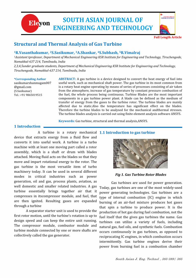
1.1 Introduction to gas turbine
Fig 1. Gas Turbine Rotor Blades
Gas turbines are used for power generation.
Today, gas turbines are one of the most widely-used
power generating technologies. Gas turbines are a
type of internal combustion (IC) engine in which
burning of an air-fuel mixture produces hot gases
that spin a turbine to produce power. It is the
production of hot gas during fuel combustion, not the
fuel itself that the gives gas turbines the name. Gas
turbines can utilize a variety of fuels, including
natural gas, fuel oils, and synthetic fuels. Combustion
occurs continuously in gas turbines, as opposed to
reciprocating IC engines, in which combustion occurs
intermittently. Gas turbine engines derive their
power from burning fuel in a combustion chamber
South Asian J. Eng. Technol, 2017, 385-389| 386
and using the fast flowing combustion gases to drive
a turbine in much the same way as the high pressure
steam drives a steam turbine.
2.COMPONENT SELECTION
2.1NICKEL-CHROMIUM ALLOY (N 155)
Ni chrome (Ni Cr, nickel-chrome, chrome-
nickel, etc.) generally refers to any alloy of nickel,
chromium, and often iron and/or other elements or
substances. Ni chrome alloys are typically used in
resistance wire. They are also used in some dental
restorations (fillings) and in other applications.
Table 1 Properties of N155
Properties Units N155
E Pa 143E09
ρ Kg/cu m 8249
K W/m-K 20.0
µ --- 0.344
α E-06/oC 17.7
Cp J/Kg K 435
Melting point OC 1354
Yield stress MPa 550
2.2 HASTE ALLOY X
Haste alloy is the registered trademark name
of Haynes International, Inc. The trademark is
applied as the prefix name of a range of twenty-two
different highly corrosion-resistant metal alloys,
loosely grouped by the metallurgical industry under
the material term “super alloys” or “high-
performance alloys”.
Table 2 Properties of Haste Alloy X
Properties Units Haste
alloy X
E Pa 144E09
Ρ Kg/cu m 8300
K W/m-K 25
µ --- 0.348
Α E-06/oC 16
Cp J/KgK 450
Melting
point OC 1380
Yield stress MPa 360
2.3 INCONEL 625
oxidation and corrosion resistant materials well
suited for service in extreme environments subjected
Inconel is a family of austenite nickel-chromium-
based super alloys. Inconel alloys are to pressure and
heat.
Table 3 properties of Inconel 625
Properties Units Inconel625
E Pa 150 E09
Ρ Kg/cu m 8400
K W/m-K 10
µ --- 0.331
Α E-06/oC 15
Cp J/KgK 410
Melting point OC 1350
Yield stress MPa 1030
3.MODELING
South Asian J. Eng. Technol, 2017, 385-389| 387
3.1 INTRODUCTION TO CAD/CAM :
CAD/CAM is a term which means computer-aided
design and computer-aided manufacturing. It is the
technology concerned with the use of digital
computers to perform certain functions in design and
production. This technology is moving in the
direction of greater integration of design and
manufacturing, two activities which have
traditionally been treated as district and separate
functions in a production firm. Computer – aided
design (CAD) can be defined as the use of computer
systems to assist in the creation, modification,
analysis, or optimization of a design. In computer-
aided design, geometricmodeling is concerned with
the computer- compatible mathematical description
of the geometry of an object. The mathematical
description allows the image of the object to be
displayed and manipulated on a graphics terminal
through signals from the CPU of the CAD system.
3.2THE DESIGN PROCESS
The process of designing is characterized by six
identifiable steps or phase
1. Recognition of need
2. Definition of problem
3. Analysis and optimization
4. Evaluation,Presentation &Synthesis
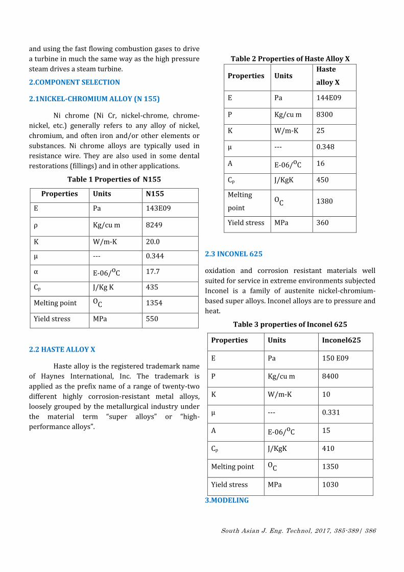
3.3 A SOLID MODELLING
Fig 3. Model in gas turbine
CAD system uses solid model supposed to be the best
complete geometric model. All the surface geometry
and wireframe are contained in it which are required
to describe fully the model's faces and edges. Apart
from geometric information, topology of solid models
are also conveyed by them. Geometry together are
also related by solid modelling. As an example,
identification of faces (surfaces) at edges (curves)
may be included in topology.
4.ANALYSIS
4.1INTRODUCTION TO FEM
In mathematics, the finite element method
(FEM) is a numerical technique for finding
approximate solutions to boundary value problems
for partial differential equations. It uses variation
methods (the calculus of variations) to minimize an
error function and produce a stable solution.
Analogous to the idea that connecting many tiny
straight lines can approximate a larger circle, FEM
encompasses all the methods for connecting many
simple element equations over many small sub
domains, named finite elements, to approximate a
more complex equation over a larger domain.The
subdivision of a whole domain into simpler parts has
several advantages:
Accurate representation of complex geometry
Inclusion of dissimilar material properties
Easy representation of the total solution
FEM is best understood from its practical
application, known as finite element analysis (FEA).
FEA as applied in engineering is a computational tool
for performing engineering analysis.
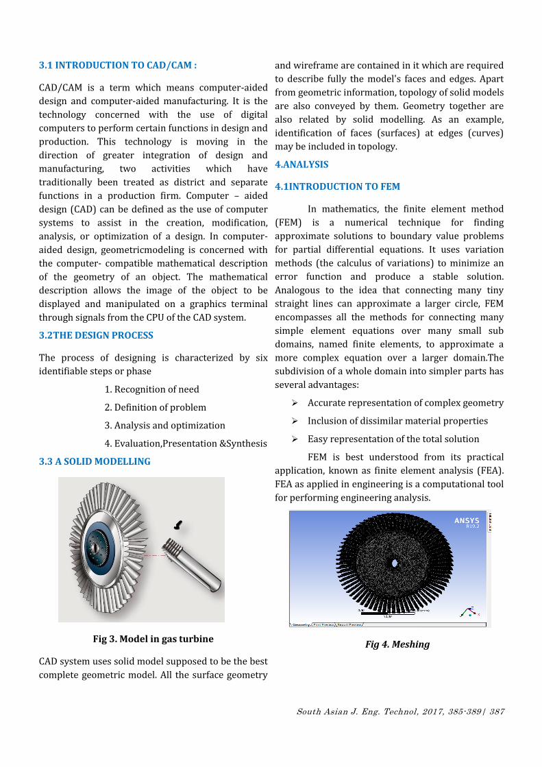
Fig 4. Meshing
South Asian J. Eng. Technol, 2017, 385-389| 388
FEM solution to the problem at left, involving a
cylindrically shaped magnetic shield. The
ferromagnetic cylindrical part is shielding the area
inside the cylinder by diverting the magnetic field
created by the coil (rectangular area on the right).
5.APPLICATION
A variety of specializations under the umbrella of the mechanical engineering discipline(suchas aeronautical, biomechanical, and automotive industries) commonly use integrated FEM in design and development of their products. Several modern FEM packages include specific components such as thermal, electromagnetic,fluid, and structural working environments. In a structural simulation, FEM helps tremendously in producing stiffness and strength visualizations.
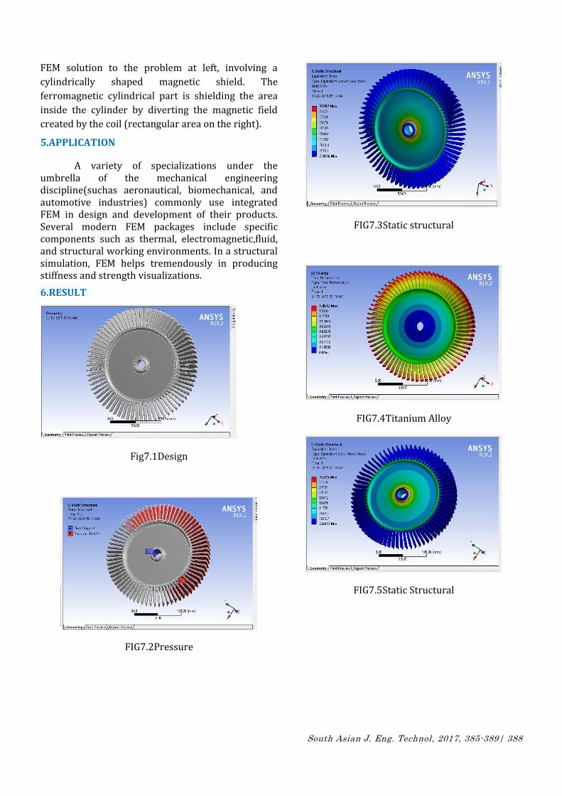
6.RESULT
Fig7.1Design
FIG7.2Pressure
FIG7.3Static structural
FIG7.4Titanium Alloy
FIG7.5Static Structural
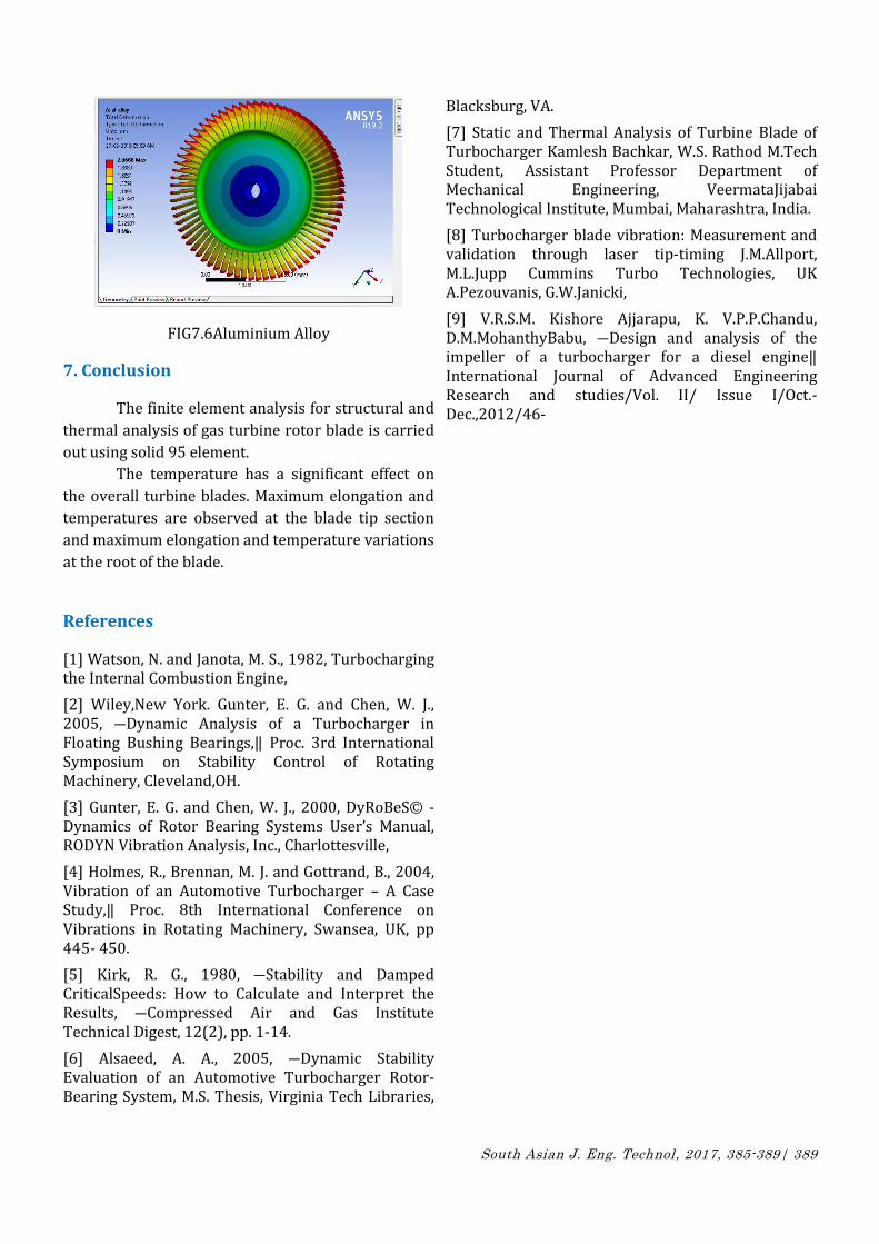
South Asian J. Eng. Technol, 2017, 385-389| 389
FIG7.6Aluminium Alloy
7. Conclusion
The finite element analysis for structural and
thermal analysis of gas turbine rotor blade is carried
out using solid 95 element.
The temperature has a significant effect on
the overall turbine blades. Maximum elongation and
temperatures are observed at the blade tip section
and maximum elongation and temperature variations
at the root of the blade.
References
[1] Watson, N. and Janota, M. S., 1982, Turbocharging the Internal Combustion Engine,
[2] Wiley,New York. Gunter, E. G. and Chen, W. J., 2005, ―Dynamic Analysis of a Turbocharger in Floating Bushing Bearings,‖ Proc. 3rd International Symposium on Stability Control of Rotating Machinery, Cleveland,OH.
[3] Gunter, E. G. and Chen, W. J., 2000, DyRoBeS© - Dynamics of Rotor Bearing Systems User’s Manual, RODYN Vibration Analysis, Inc., Charlottesville,
[4] Holmes, R., Brennan, M. J. and Gottrand, B., 2004, Vibration of an Automotive Turbocharger – A Case Study,‖ Proc. 8th International Conference on Vibrations in Rotating Machinery, Swansea, UK, pp 445- 450.
[5] Kirk, R. G., 1980, ―Stability and Damped CriticalSpeeds: How to Calculate and Interpret the Results, ―Compressed Air and Gas Institute Technical Digest, 12(2), pp. 1-14.
[6] Alsaeed, A. A., 2005, ―Dynamic Stability Evaluation of an Automotive Turbocharger Rotor- Bearing System, M.S. Thesis, Virginia Tech Libraries,
Blacksburg, VA.
[7] Static and Thermal Analysis of Turbine Blade of Turbocharger Kamlesh Bachkar, W.S. Rathod M.Tech Student, Assistant Professor Department of Mechanical Engineering, VeermataJijabai Technological Institute, Mumbai, Maharashtra, India.
[8] Turbocharger blade vibration: Measurement and validation through laser tip-timing J.M.Allport, M.L.Jupp Cummins Turbo Technologies, UK A.Pezouvanis, G.W.Janicki,
[9] V.R.S.M. Kishore Ajjarapu, K. V.P.P.Chandu, D.M.MohanthyBabu, ―Design and analysis of the impeller of a turbocharger for a diesel engine‖ International Journal of Advanced Engineering Research and studies/Vol. II/ Issue I/Oct.-Dec.,2012/46-