Embed Size (px)
Citation preview
®
WORCESTER CONTROLS F519/529/819/829Full Bore Fire Safe Flanged Ball Valves
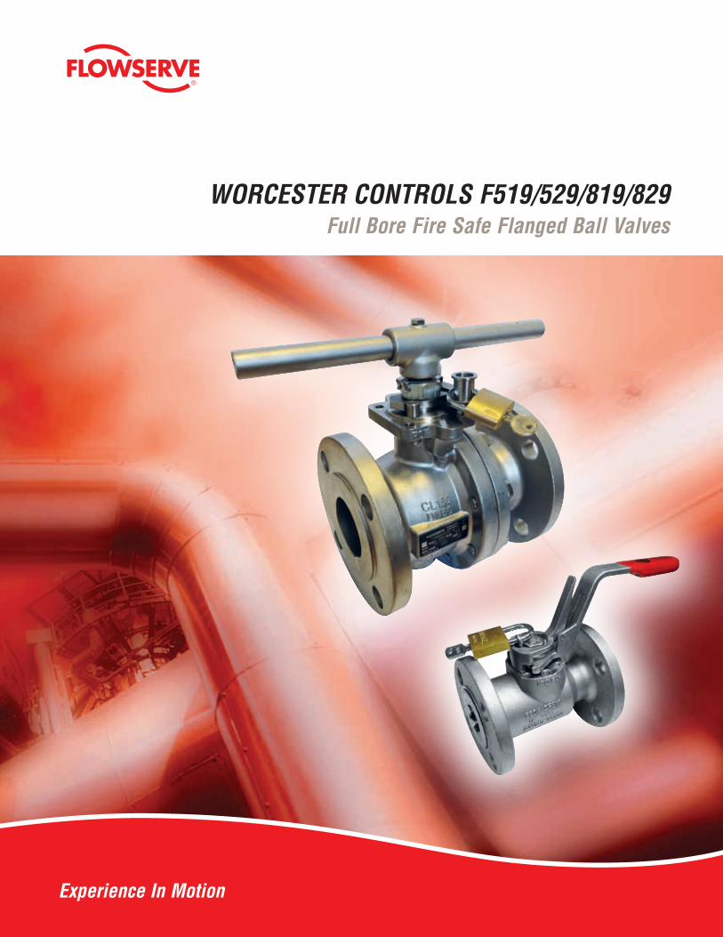
Anti-blowout stemInserted from inside of valve body for greater safety
Actuator MountingConforms to ISO 5211 for ease of actuation
Anti-static stem designEnsures electrical continuity between ball and body
BallParallel ported 316 stainless steel as standard with pressure equalizing hole to balance cavity pressure when the valve is open
Body sealsPTFE with metal to metal secondary seal on one-piece valves and PTFE coated graphite on two piece eliminating potential media contamination whilst providing fire rated integrity
Gland packingGraphite provides fire rated integrity and combined with the body seals ensures Fugitive Emission com-pliance to ISO 15848
WrenchErgonomically designed tamper proof lockable design on one-piece valves and multi position fit wrench on two-piece valves to suit space require-ments
Locking clipMaintains position of gland nut during actuation for long leak-free performance
ActuationValve assembled ready for actuation with no chang-es to stem build required maintaining valve integrity
BoltingStainless steel as standard meeting the require-ments of ASME VIII Div 1 pressure vessel codes
Locking DeviceTamper proof design ensures the padlock cannot be removed or over-ridden when locked either open or closed (North America & Canada only)
The Flowserve Worcester flanged full bore valve range provides customers with specification compliant product with long service free life resulting in low cost of ownership. All valves com-ply with the requirements of ASME B.16.34 with a one piece 519/529 design up to 1½” and the two piece design extending the range from 2” to 8”
2
®
2
17
1918
14
12
10
11
9
18
4
20
5
6
7
3
15
13
16
Series 819/829
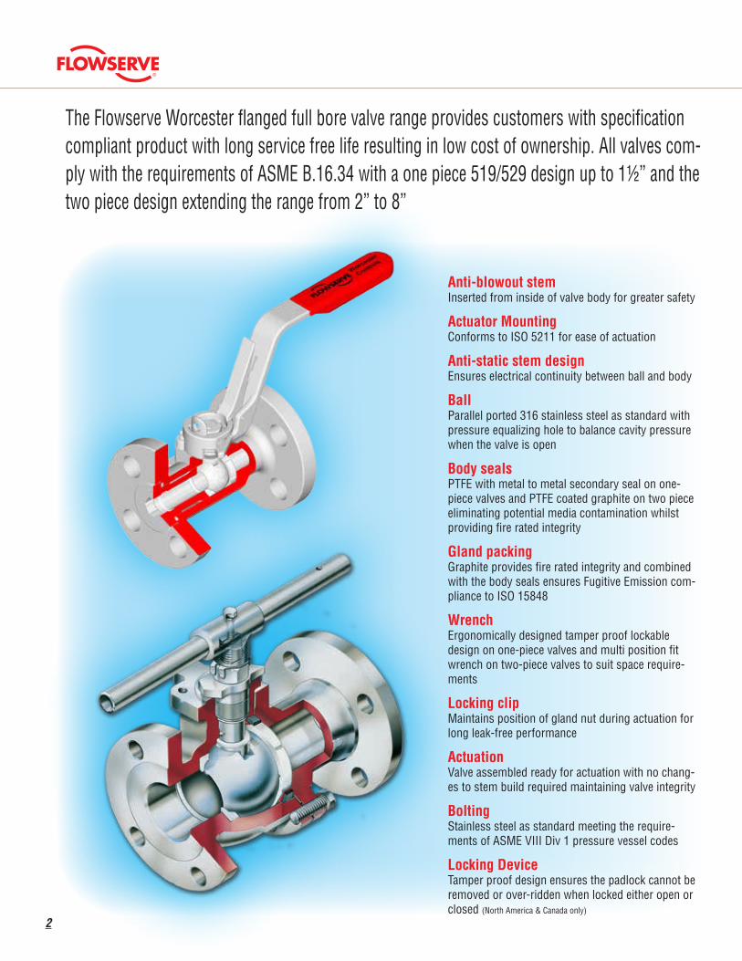
Parts/Materials List
Item Description Material Item Description Material
1 & 2 Body & Insert/Connector Stainless Steel ASTM-A351 CF8MLow Temp Carbon Steel ASTM-A352 LCB 14 Gland nut Zinc Plated Stainless Steel. Carbon Steel
3 Ball Stainless Steel A479 316, ASTM-A351 CF8M 15 Gland Nut Locking Clip Stainless Steel
4 Stem Stainless Steel A479 316 16 Stop Pin Stainless Steel
5 Seat TFE Virgin, Polyfill (see page 6) 17 Wrench Stainless Steel, Carbon Steel
6 Body Seal PTFE / PTFE Coated Flexible Graphite 18 Wrench Head Stainless Steel, Carbon Steel
7 Body Connector Screw Stainless Steel ASTM A193M, B8 CL2/B8M CL2 19 Wrench attachment Bolt Stainless Steel, Carbon Steel
8 Stem Thrust Seal TFE, Polyfill 20 Anti-static Spring & Plunger Stainless Steel
9 Secondary Stem Seal TFE 21 Locking /device Stainless Steel
10 Gland Packing TFE, Flexible Graphite 22 Washer Stainless Steel
11 Stem location ring Stainless steel 316 23 Lockwasher Stainless Steel
12 Indicator Stop Stainless Steel 24 Washer Stainless Steel
13 Gland Stainless steel 316 25 Nut Stainless Steel
17
6
84
205
23
1
25231514221624
13
10
Series 519/529
21
3

Valve Dimensions 519/529 inch/mm
Ø ‘V’ MINIMUM CLEARANCE HOLEFOR MOUNTING BRACKET
STEM ‘F’ ACROSS FLATS‘G’ DIAMETER
CLOCKWISETO CLOSE
MOUNTING PLATFORM DRILLING/LOCATIONBS EN ISO 5211 (SEE DIMENSION TABLE)
PADLOCK NOT SUPPLIED
PADLOCKHOLE: Ø 7.0
E
C
J D M
M
T2
T2
T1 T1
A B
PORT
DIA
MET
ER
K
4
®
Valve Size
Port Dia. Min.
AB C D E
StemJ K M T1 T2 V
Mountig Platform
F519 F529F G ISO
Size PCD Thread DepthMinA/F Thread
½" 0.54 4.25 5.5 2.07 0.9160.906
0.6910.664
0.4210.401
0.2180.215
3/8"-24UNF 3.74 6.10 0.63 0.75 0.91 0.77 F03 1.42 M5 0.31
DN15 13.7 108.0 140.0 52.5 23.2723.01
17.5616.86
10.6910.19
5.545.46
3/8"-24UNF 95.0 155.0 15.9 19.0 23.0 19.5 F03 36.0 M5 8.0
¾" 0.79 4.61 6.0 2.24 1.2731.263
0.9350.902
0.5980.578
0.2970.294
7/16"-20UNF 4.17 6.61 0.81 0.87 1.06 0.89 F04 1.65 M5 0.31
DN20 20.0 117.0 152.0 57.0 32.3432.08
23.7622.92
15.1914.69
7.547.47
7/16"-20UNF 105.8 168.0 20.7 22.0 27.0 22.5 F04 42.0 M5 8.0
1" 1.00 5.00 6.5 2.48 1.4611.451
0.9350.902
0.5980.578
0.2970.294
7/16"-20UNF 4.35 6.61 0.81 0.87 1.06 0.89 F04 1.65 M5 0.31
DN25 25.3 127.0 165.0 63.0 37.1136.85
23.7422.90
15.1914.69
7.547.47
7/16"-20UNF 110.5 168.0 20.7 22.0 27.0 22.5 F04 42.0 M5 8.0
1½" 1.48 6.50 7.5 2.68 1.9201.909
1.1631.130
0.7240.704
0.3430.340
9/16"- 18UNF 5.19 7.76 0.88 0.98 1.28 1.16 F05 1.97 M6 0.39
DN40 37.7 165.0 190.0 68.0 48.7648.50
29.5529.71
"18.3917.89"
8.718.64
9/16"- 18UNF 131.7 197.0 22.3 25.0 32.5 29.5 F05 50.0 M6 10.0
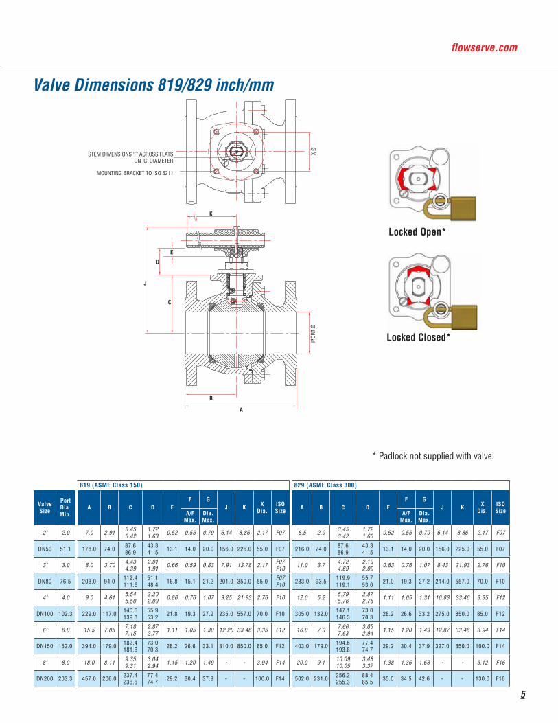
Valve Dimensions 819/829 inch/mm
Locked Open*
Locked Closed*
* Padlock not supplied with valve.
STEM DIMENSIONS F ACROSS FLATSON G DIAMETER
MOUNTING PLATFORM TO ISO 5211
PORT
Ø
K
J
D
E
B
A
X Ø
C
STEM DIMENSIONS ‘F’ ACROSS FLATS ON ‘G’ DIAMETER
MOUNTING BRACKET TO ISO 5211
PORT
Ø
X Ø
5
819 (ASME Class 150) 829 (ASME Class 300)
Valve Size
Port Dia. Min.
A B C D EF G
J K XDia.
ISOSize A B C D E
F GJ K X
Dia.ISOSizeA/F
Max.Dia.Max.
A/FMax.
Dia.Max.
2" 2.0 7.0 2.91 3.453.42
1.721.63 0.52 0.55 0.79 6.14 8.86 2.17 F07 8.5 2.9 3.45
3.421.721.63 0.52 0.55 0.79 6.14 8.86 2.17 F07
DN50 51.1 178.0 74.0 87.686.9
43.841.5 13.1 14.0 20.0 156.0 225.0 55.0 F07 216.0 74.0 87.6
86.943.841.5 13.1 14.0 20.0 156.0 225.0 55.0 F07
3" 3.0 8.0 3.70 4.434.39
2.011.91 0.66 0.59 0.83 7.91 13.78 2.17 F07
F10 11.0 3.7 4.724.69
2.192.09 0.83 0.76 1.07 8.43 21.93 2.76 F10
DN80 76.5 203.0 94.0 112.4111.6
51.148.4 16.8 15.1 21.2 201.0 350.0 55.0 F07
F10 283.0 93.5 119.9119.1
55.753.0 21.0 19.3 27.2 214.0 557.0 70.0 F10
4" 4.0 9.0 4.61 5.545.50
2.202.09 0.86 0.76 1.07 9.25 21.93 2.76 F10 12.0 5.2 5.79
5.762.872.78 1.11 1.05 1.31 10.83 33.46 3.35 F12
DN100 102.3 229.0 117.0 140.6139.8
55.953.2 21.8 19.3 27.2 235.0 557.0 70.0 F10 305.0 132.0 147.1
146.373.070.3 28.2 26.6 33.2 275.0 850.0 85.0 F12
6" 6.0 15.5 7.05 7.187.15
2.872.77 1.11 1.05 1.30 12.20 33.46 3.35 F12 16.0 7.0 7.66
7.633.052.94 1.15 1.20 1.49 12.87 33.46 3.94 F14
DN150 152.0 394.0 179.0 182.4181.6
73.070.3 28.2 26.6 33.1 310.0 850.0 85.0 F12 403.0 179.0 194.6
193.877.474.7 29.2 30.4 37.9 327.0 850.0 100.0 F14
8" 8.0 18.0 8.11 9.359.31
3.042.94 1.15 1.20 1.49 - - 3.94 F14 20.0 9.1 10.09
10.053.483.37 1.38 1.36 1.68 - - 5.12 F16
DN200 203.3 457.0 206.0 237.4236.6
77.474.7 29.2 30.4 37.9 - - 100.0 F14 502.0 231.0 256.2
255.388.485.5 35.0 34.5 42.6 - - 130.0 F16

Pressure/Temperature RatingsTFE SEATS (T)Virgin PTFE is the most common sealing material and is suitablefor almost all media as it has excellent chemical resistance.
POLYFILL / FLUOROFILL (P)Carbon and graphite filled PTFE material an excellent seat material for higher pressure and temperature applications.
-51 32 122 212 302 392 482 572
Temperature (°C)
Pres
sure
(bar
)
Temperature (°F)
Pres
sure
(psi
)
1160
1015
870
725
580
435
290
145
0
80
70
60
50
40
30
20
10
0
-46 0 50 100 150 200 250 300
Class300
Class150
Temperature (°C)
Pres
sure
(bar
)
Temperature (°F)
Pres
sure
(psi
)
-51 32 122 212 302 392 482 572
1160
1015
870
725
580
435
290
145
0
80
70
60
50
40
30
20
10
0
-46 0 50 100 150 200 250 300
Class300
Class150
2" - 8"
½" - 1½
"
KEY: A = Carbon steel body rating B = Stainless steel body rating
Pressure Torque Curves
Note: Please apply safety factors as recommended in the Worcester Controls Actuator Sizing Manual
519/529 TFE & POLYFILL SEATS 819/829 TFE & POLYFILL SEATS
0
1000
2000
3000
4000
5000
6000
7000
8000
9000
10000
11000
12000
0 100 200 300 400 500 600 700
Torq
ue (i
n-lb
)
Differential Pressure (psi)
1356
1243
1130
1017
904
791
678
565
452
339
226
113
0,0
Torq
ue (N
m)
Differential Pressure (bar)
0 6.9 13.8 20.7 27.6 34.5 41.4 48.3
8"
6"
4"
3"
2"0
50
100
150
200
250
300
350
0 100 200 300 400 500 600 700
Torq
ue (i
n-lb
)
Differential Pressure (psi)
Differential Pressure (bar)
0 6.9 13.8 20.7 27.6 34.5 41.4 48.339.5
34.0
28.2
22.3
17.0
11.3
5.6
0
Torq
ue (N
m)
1 "
1"
"
"
6
®
A B C D E F G
Size Standard Variant Series
Body
Inse
rt/Co
nn
Ball
Stem
Seat
Body
Sea
l
Thru
st S
eal
Seco
nday
Stem
Sea
l
Glan
d Pa
ckin
g
Flange Build Variation
A - Size B - Std Variant C - Series D - Main Parts E - Seat & Seals F - Flange G - Build Variation
½" 15mm 05 Fire rated F 519 Series 519 Low-Temp Carbon Steel 5 Virgin TFE T Class 150 150 V3 - Vented Ball
¾" 20mm 07 529 Series 529 Stainless Steel 6 Polyfill/Fluorofill P Class 300 300 V32 - Oval Handle
1" 25mm 10 819 Series 819 Graphite Z V38 - Assembled Dry
1½" 40mm 15 829 Series 829 V46 - Silicone Free
2" 50mm 20 V66 - European C of C
3" 80mm 30 V72 - PED Compliance
4" 100mm 40 V73 - Cavity fillers
6" 150mm 60 V91 - API 608 Compliance
8" 200mm 80
How to Order (Typical)
Standards of Compliance
Valve Size SeriesWeight Limiting Stem Torque Flow Coefficients
lbs Kg lb-in Nm Cv Kv
½” DN15519 4.0 1.8 69 7.8 32 27529 4.9 2.2 69 7.8 32 27
¾” DN20519 5.3 2.4 157 17.7 54 46529 7.7 3.5 157 17.7 54 46
1” DN25519 7.1 3.2 157 17.7 94 80529 10.1 4.6 157 17.7 94 80
1½” DN40519 12.8 5.8 299 33.8 254 219529 19.0 8.6 299 33.8 254 219
2” DN50819 26.5 12.0 1042 118 501 423829 33.1 15.0 1042 118 501 423
3” DN80819 48.5 22.0 1838 208 1158 978829 70.5 32.0 3083 348 1158 978
4” DN100819 88.2 40.0 3080 348 2118 1789829 125.7 57.0 6774 765 2118 1789
6” DN150819 194.0 88.0 6774 765 5074 4287829 257.9 117.0 10100 1141 5074 4287
8” DN200819 388.0 176.0 10100 1141 9337 7889829 520.3 236.0 14503 1639 9337 7889
Cv - Flow in US GPM Pressure psi Kv - Flow in M3/hr Pressure - bar
Technical Information
7
Valve Specification ASME B.16.34 / ISO 17292Face to Face Lengths 519/819 (Class 150)
ASME B16.10 Column 19 Short ½” - 4”ASME B16.10 Column 18 Long 6” - 8”EN558 Table 2 Series 3½” - 4”EN558 Table 2 Series 12 6” - 8”529/829 (Class 300)ASME B16.10 Column 8 Short ½” - 6”ASME B16.10 Column 7 Long 8”EN558 Table 2 Series 4 ½” - 6”
Quality Assurance ISO 9001
Fire rating API 607ISO 10497(Graphite build only)
Pressure Test API 598Fugitive Emission EN 15848
(Graphite build only)Sour GasApplications
NACE MR.01.75 / ISO 15156(Internal Only)
Flanges ASME B.16.5 Class 150 & 300BS EN 1759-1 Class 150 & 300
© 2016 Flowserve Corporation. Irving. Texas. USA. Flowserve and Worcester Controls are registered trademarks of Flowserve Corporation.
Flowserve Corporation has established industry leadership in the design and manufacture of its products. When properly selected. this Flowserve product is designed to perform its intended function safely during its useful life. However. the purchaser or user of Flowserve products should be aware that Flowserve products might be used in numerous applications under a wide variety of industrial service conditions. Although Flowserve can (and often does) provide general guidelines. it cannot provide specific data and war-nings for all possible applications. The purchaser/user must therefore assume the ultimate responsibility for the proper sizing and selection. installation. operation. and main-tenance of Flowserve products. The purchaser/user should read and understand the Installation Operation Maintenance (IOM) instructions included with the product. and train its employees and contractors in the safe use of Flowserve products in connection with the specific application.
While the information and specifications contained in this literature are believed to be accurate. they are supplied for informative purposes only and should not be considered certified or as a guarantee of satisfactory results by reliance thereon. Nothing contained herein is to be construed as a warranty or guarantee. express or implied. regarding any matter with respect to this product. Because Flowserve is continually improving and upgrading its product design. the specifications. dimensions and information contained herein are subject to change without notice. Should any question arise concerning these provisions. the purchaser/user should contact Flowserve Corporation at any one of its worldwide operations or offices.
Flowserve CorporationFlow Control Division1978 Foreman DriveCookeville. Tennessee38501 USATelephone: +931 432 4021Fax: +931 432 5518
Flowserve Flow ControlA Division of Flowserve GB Ltd.Burrell Road. Haywards HeathWest Sussex RH16 1TLUnited KingdomTelephone: +44 (0)1444 314400Telefax: +44 (0)1444 31440Email: [email protected]
Flowserve CorporationNo. 35. Baiyu RoadSuzhou Industrial ParkSuzhou 215021Jiangsu Province. PRCTelephone: +86 512 6288 1688Fax: +86 512 6288 8737Email: [email protected]
FCD WCENBR0032-00 AQ 08/2016 Printed in USA.
For more information about Flowserve Corporation. visit www.flowserve.com or call USA 1-800-225-6989.
Contact:
FCD WCENBR0032-01 AQ 04/17 Printed in USA.
8
®