Embed Size (px)
Citation preview
All Rights Reserved ©2011The Tokyo Electric Power Company, Inc. 0
Fukushima Nuclear Accident Interim Report:
Effects of the Earthquake and Tsunami on the Fukushima Daiichi and Daini Nuclear Power Stations, especially on electric and I&C systems and equipments
July 27, 2011@IEEE Nuclear Power Engineering Committee
Akira KawanoTokyo Electric Power Company
All Rights Reserved ©2011The Tokyo Electric Power Company, Inc. 1
What I will present
1.What occurred at Fukushima Daiichi (1F) & Daini (2F) in Japan ?
- Earthquake - Tsunami2.What made the difference between 1F and 2F ?- Electric equipment - Instrumentation & Control- Transmission lines
3. How we responded ?- What difficulties existed- What were effectively utilized
4. Current status and Roadmap5. Summary6. References- Damage status of electric equipments - Restoration process- Measures to ensure safe shutdown - Chronology
All Rights Reserved ©2011The Tokyo Electric Power Company, Inc. 2
1.What occurred at Fukushima Daiichi (1F) & Daini (2F) in Japan ?
- Earthquake - Tsunami
All Rights Reserved ©2011The Tokyo Electric Power Company, Inc. 3
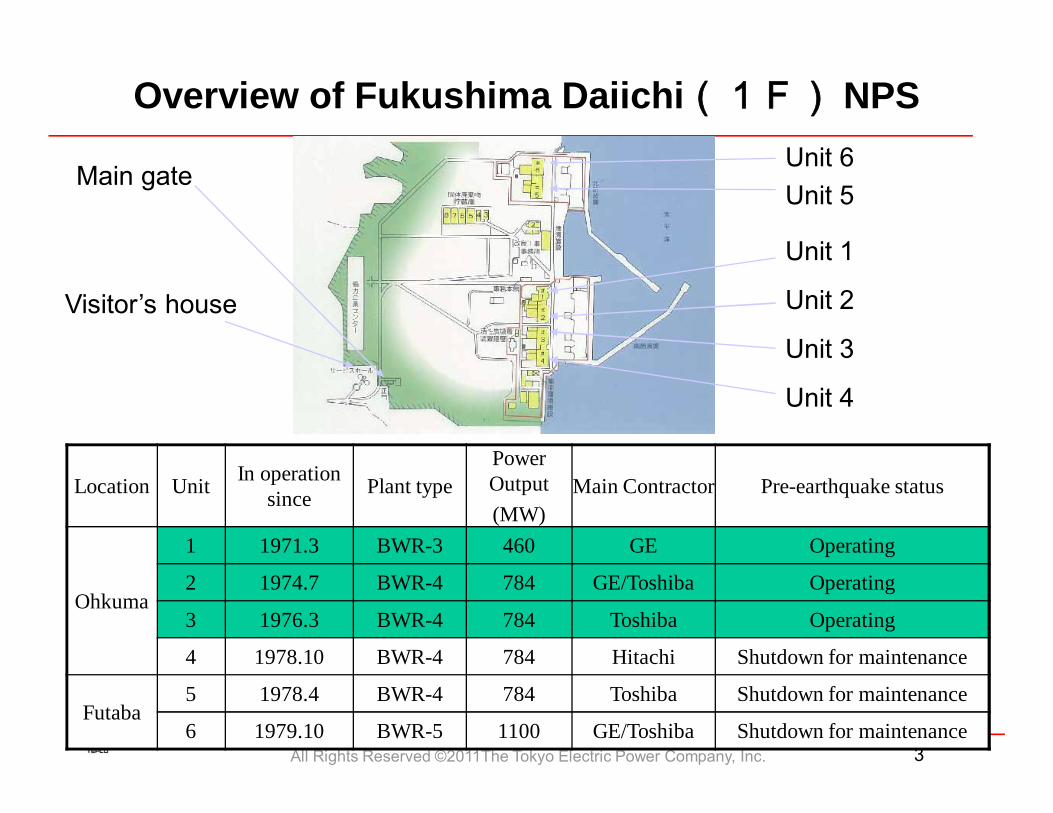
Location Unit In operation since Plant type
Power Output(MW)
Main Contractor Pre-earthquake status
Ohkuma
1 1971.3 BWR-3 460 GE Operating
2 1974.7 BWR-4 784 GE/Toshiba Operating
3 1976.3 BWR-4 784 Toshiba Operating
4 1978.10 BWR-4 784 Hitachi Shutdown for maintenance
Futaba5 1978.4 BWR-4 784 Toshiba Shutdown for maintenance
6 1979.10 BWR-5 1100 GE/Toshiba Shutdown for maintenance
Unit 1
Unit 2
Unit 3
Unit 4
Unit 6Unit 5
Main gate
Visitor’s house
Overview of Fukushima Daiichi(1F) NPS
All Rights Reserved ©2011The Tokyo Electric Power Company, Inc. 4
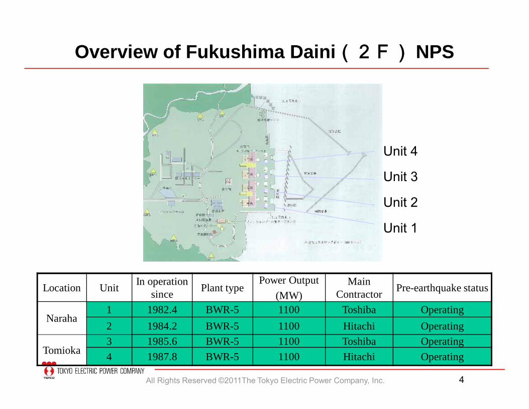
Location Unit In operation since Plant type
Power Output(MW)
Main Contractor Pre-earthquake status
Naraha1 1982.4 BWR-5 1100 Toshiba Operating2 1984.2 BWR-5 1100 Hitachi Operating
Tomioka3 1985.6 BWR-5 1100 Toshiba Operating4 1987.8 BWR-5 1100 Hitachi Operating
Unit 4
Unit 3
Unit 2
Unit 1
Overview of Fukushima Daini(2F) NPS
All Rights Reserved ©2011The Tokyo Electric Power Company, Inc. 5
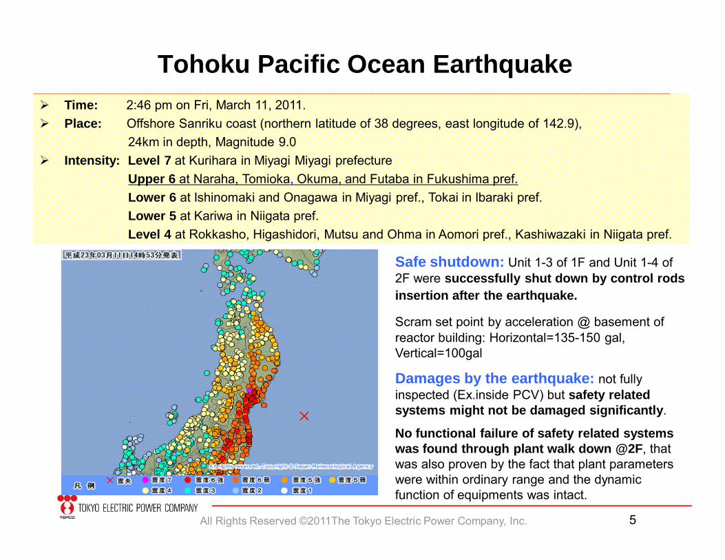
Tohoku Pacific Ocean Earthquake Time: 2:46 pm on Fri, March 11, 2011. Place: Offshore Sanriku coast (northern latitude of 38 degrees, east longitude of 142.9),
24km in depth, Magnitude 9.0 Intensity: Level 7 at Kurihara in Miyagi Miyagi prefecture
Upper 6 at Naraha, Tomioka, Okuma, and Futaba in Fukushima pref.Lower 6 at Ishinomaki and Onagawa in Miyagi pref., Tokai in Ibaraki pref.Lower 5 at Kariwa in Niigata pref.Level 4 at Rokkasho, Higashidori, Mutsu and Ohma in Aomori pref., Kashiwazaki in Niigata pref.
Safe shutdown: Unit 1-3 of 1F and Unit 1-4 of 2F were successfully shut down by control rods insertion after the earthquake.
Scram set point by acceleration @ basement of reactor building: Horizontal=135-150 gal, Vertical=100gal
Damages by the earthquake: not fully inspected (Ex.inside PCV) but safety related systems might not be damaged significantly.
No functional failure of safety related systems was found through plant walk down @2F, that was also proven by the fact that plant parameters were within ordinary range and the dynamic function of equipments was intact.
All Rights Reserved ©2011The Tokyo Electric Power Company, Inc. 6
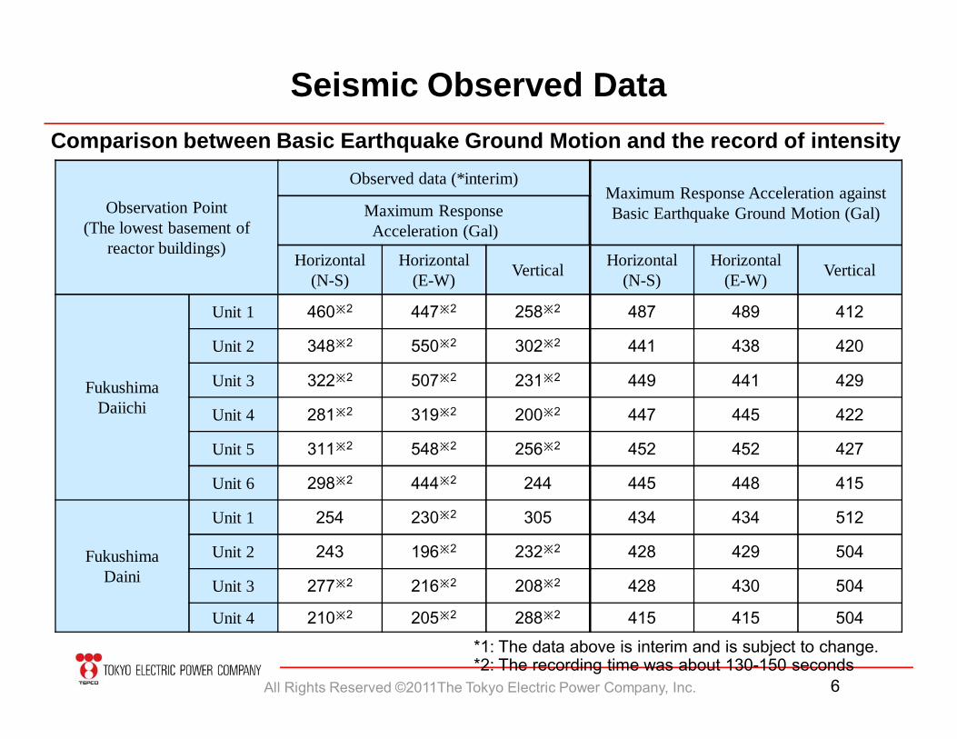
Seismic Observed Data
Observation Point(The lowest basement of
reactor buildings)
Observed data (*interim)Maximum Response Acceleration against Basic Earthquake Ground Motion (Gal)Maximum Response
Acceleration (Gal)
Horizontal(N-S)
Horizontal(E-W) Vertical Horizontal
(N-S)Horizontal
(E-W) Vertical
FukushimaDaiichi
Unit 1 460※2 447※2 258※2 487 489 412
Unit 2 348※2 550※2 302※2 441 438 420
Unit 3 322※2 507※2 231※2 449 441 429
Unit 4 281※2 319※2 200※2 447 445 422
Unit 5 311※2 548※2 256※2 452 452 427
Unit 6 298※2 444※2 244 445 448 415
FukushimaDaini
Unit 1 254 230※2 305 434 434 512
Unit 2 243 196※2 232※2 428 429 504
Unit 3 277※2 216※2 208※2 428 430 504
Unit 4 210※2 205※2 288※2 415 415 504
Comparison between Basic Earthquake Ground Motion and the record of intensity
*1: The data above is interim and is subject to change.*2: The recording time was about 130-150 seconds
All Rights Reserved ©2011The Tokyo Electric Power Company, Inc. 7
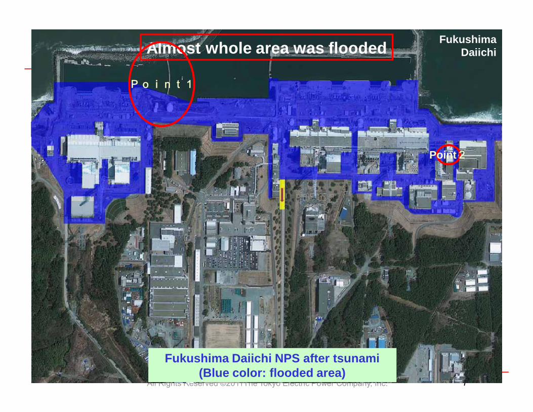
Fukushima Daiichi NPS after tsunami (Blue color: flooded area)
Fukushima Daiichi
Point2
Almost whole area was flooded
Point1
All Rights Reserved ©2011The Tokyo Electric Power Company, Inc. 8
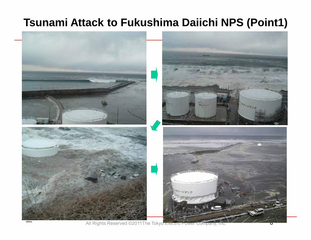
Tsunami Attack to Fukushima Daiichi NPS (Point1)
All Rights Reserved ©2011The Tokyo Electric Power Company, Inc. 9
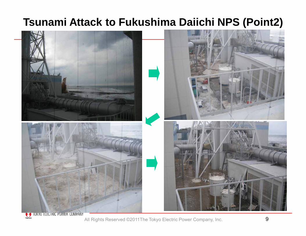
Tsunami Attack to Fukushima Daiichi NPS (Point2)
All Rights Reserved ©2011The Tokyo Electric Power Company, Inc. 10
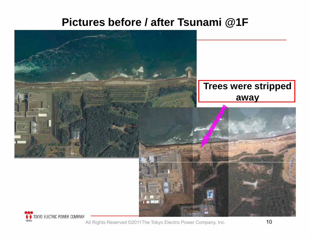
Trees were stripped away
Pictures before / after Tsunami @1F
All Rights Reserved ©2011The Tokyo Electric Power Company, Inc. 11
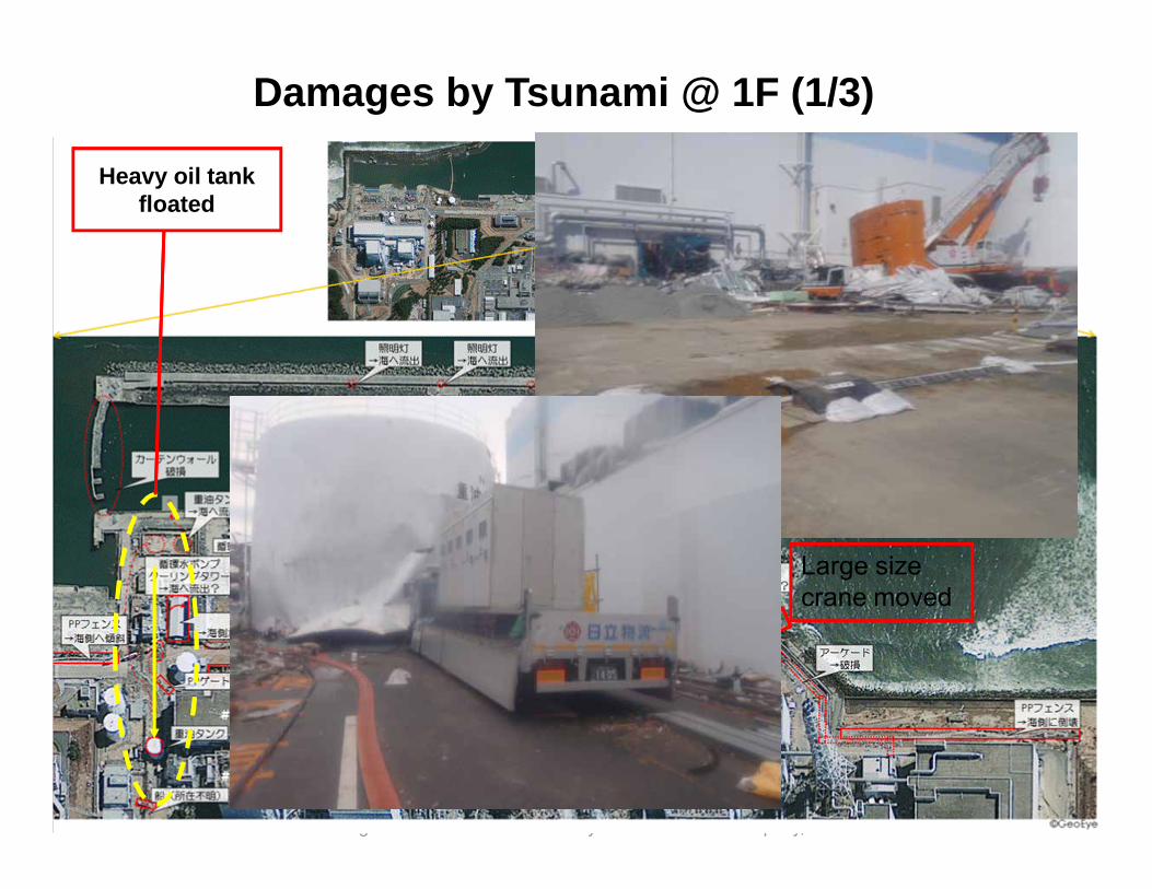
Damages by Tsunami @ 1F (1/3)
Heavy oil tank floated
Large size crane moved
All Rights Reserved ©2011The Tokyo Electric Power Company, Inc. 12
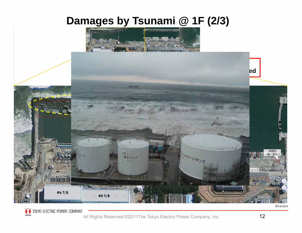
Breakwater was corrupted
Damages by Tsunami @ 1F (2/3)
All Rights Reserved ©2011The Tokyo Electric Power Company, Inc. 13
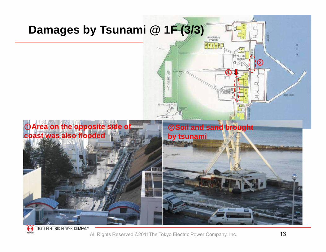
①Area on the opposite side of coast was also flooded
①②
②Soil and sand brought by tsunami
Damages by Tsunami @ 1F (3/3)
All Rights Reserved ©2011The Tokyo Electric Power Company, Inc. 14
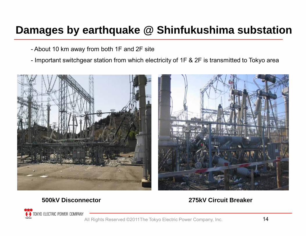
Damages by earthquake @ Shinfukushima substation
500kV Disconnector 275kV Circuit Breaker
- About 10 km away from both 1F and 2F site
- Important switchgear station from which electricity of 1F & 2F is transmitted to Tokyo area
All Rights Reserved ©2011The Tokyo Electric Power Company, Inc. 15
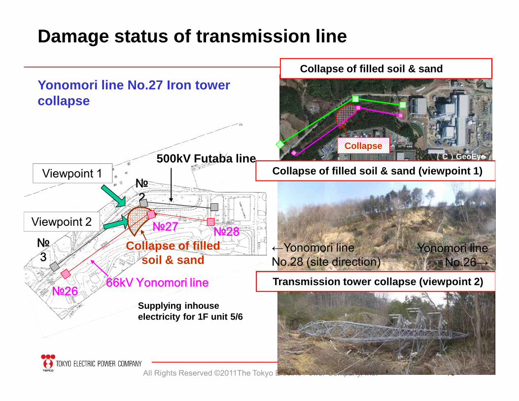
500kV Futaba line
№2
№3
66kV Yonomori line
№27 №28
№26
Collapse of filled soil & sand
Viewpoint 1
Viewpoint 2
←Yonomori line No.28 (site direction)
Yonomori line No.26→
Collapse(C)GeoEye
Collapse of filled soil & sand
Collapse of filled soil & sand (viewpoint 1)
Transmission tower collapse (viewpoint 2)
Yonomori line No.27 Iron tower collapse
Damage status of transmission line
Supplying inhouse electricity for 1F unit 5/6
All Rights Reserved ©2011The Tokyo Electric Power Company, Inc. 16
2.What made the difference between 1F and 2F ?
- Electric equipment- Instrumentation & Control- Transmission lines
All Rights Reserved ©2011The Tokyo Electric Power Company, Inc. 17
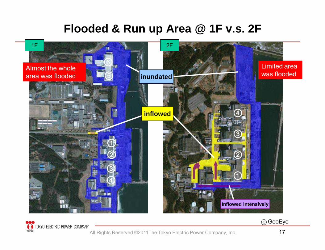
Flooded & Run up Area @ 1F v.s. 2F
GeoEye
1F 2F
inflowed
inundated
⑥⑤
①②③④
④
③
②
①
C
Inflowed intensively
Almost the whole area was flooded
Limited area was flooded
All Rights Reserved ©2011The Tokyo Electric Power Company, Inc. 18
Base levelO.P.0m
Reactor building
Ocean-side area Main building area
breakwater
Design basis tsunami height O.P.+5.2m
Site levelO.P. +12m
Water intake
Inundation height apx. O.P. +6.5 - 7mSafety measures has taken
against 5.2m Tsunami heightSite level O.P. +4m
Turbine building
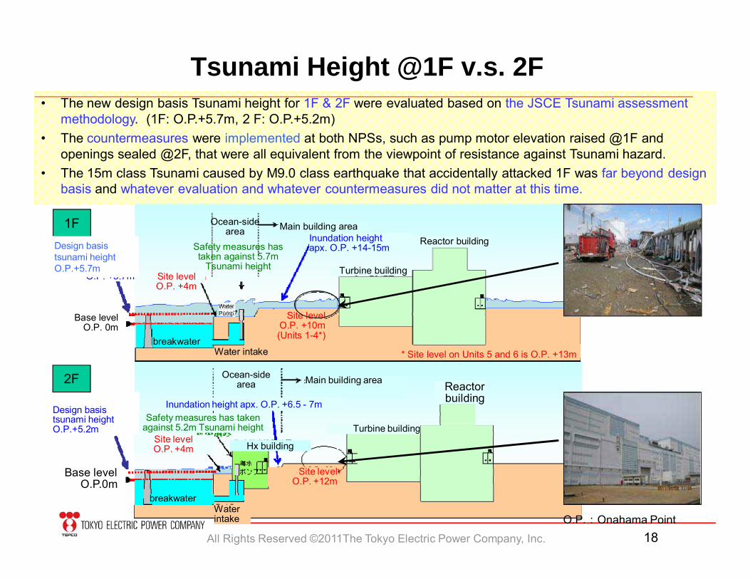
Tsunami Height @1F v.s. 2F
4月9日記者発表
• The new design basis Tsunami height for 1F & 2F were evaluated based on the JSCE Tsunami assessment methodology. (1F: O.P.+5.7m, 2 F: O.P.+5.2m)
• The countermeasures were implemented at both NPSs, such as pump motor elevation raised @1F and openings sealed @2F, that were all equivalent from the viewpoint of resistance against Tsunami hazard.
• The 15m class Tsunami caused by M9.0 class earthquake that accidentally attacked 1F was far beyond design basis and whatever evaluation and whatever countermeasures did not matter at this time.
1F
2F
O.P.:Onahama Point
Hx building
Assumed highest tsunami water level
O.P. +5.7m
Base levelO.P. 0m
-
-
-
-Assumed highest
tsunami water levelO.P. +5.7m
Base levelO.P. 0m
Site levelO.P. +10m(Units 1-4*)
* Site level on Units 5 and 6 is O.P. +13m
Turbine building
Reactor buildingInundation heightapx. O.P. +14-15m
Ocean-side area Main building area
Water intake
Site level O.P. +4m
Safety measures has taken against 5.7m
Tsunami height
breakwater
Water Pump
Assumed highest tsunami water level
O.P. +5.7m
Base levelO.P. 0m
Site levelO.P. +10m(Units 1-4*)
* Site level on Units 5 and 6 is O.P. +13m
Turbine building
Reactor buildingInundation heightapx. O.P. +14-15m
Ocean-side area Main building area
Water intake
Site level O.P. +4m
Safety measures has taken against 5.7m
Tsunami height
breakwater
Water Pump
Design basis tsunami height O.P.+5.7m
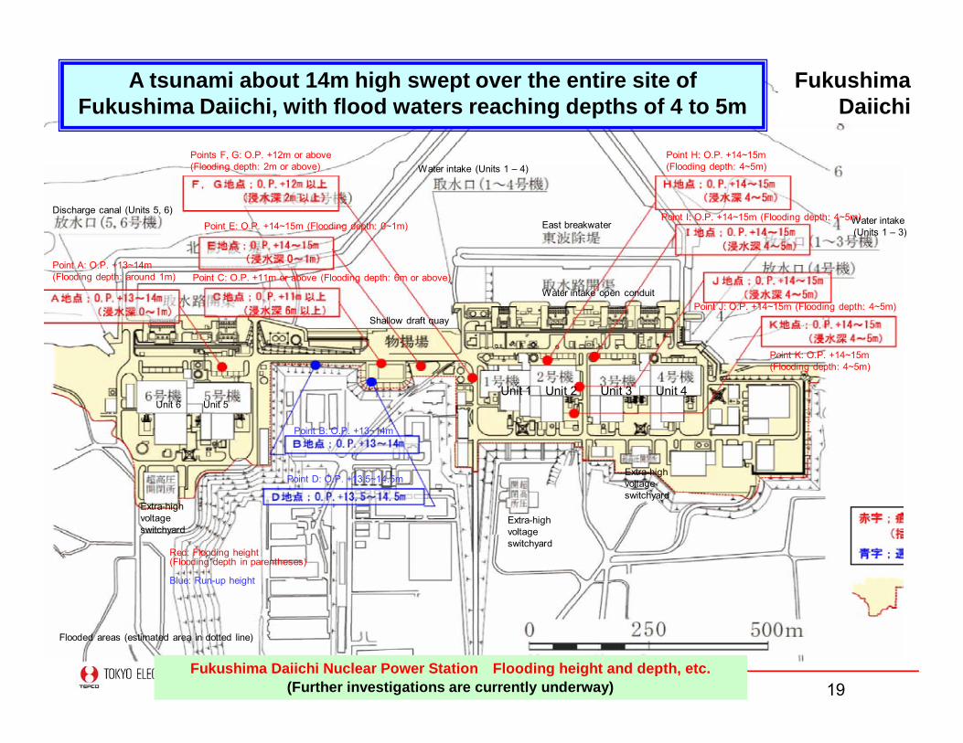
All Rights Reserved ©2011The Tokyo Electric Power Company, Inc. 19Fukushima Daiichi Nuclear Power Station Flooding height and depth, etc.
(Further investigations are currently underway)
A tsunami about 14m high swept over the entire site of Fukushima Daiichi, with flood waters reaching depths of 4 to 5m
Fukushima Daiichi
Point A: O.P. +13~14m (Flooding depth: around 1m)
Points F, G: O.P. +12m or above (Flooding depth: 2m or above)
Point E: O.P. +14~15m (Flooding depth: 0~1m)
Point C: O.P. +11m or above (Flooding depth: 6m or above)
Point H: O.P. +14~15m (Flooding depth: 4~5m)
Point I: O.P. +14~15m (Flooding depth: 4~5m)
Point J: O.P. +14~15m (Flooding depth: 4~5m)
Point K: O.P. +14~15m (Flooding depth: 4~5m)
Discharge canal (Units 5, 6)
Water intake (Units 1 – 4)
East breakwater
Point B: O.P. +13~14m
Point D: O.P. +13.5~14.5m
Red: Flooding height(Flooding depth in parentheses)
Blue: Run-up height
Flooded areas (estimated area in dotted line)
Unit 1 Unit 2 Unit 3 Unit 4Unit 6 Unit 5
Water intake open conduit
Shallow draft quay
Extra-high voltage switchyard
Extra-high voltage switchyard
Extra-high voltage switchyard
Water intake(Units 1 – 3)
All Rights Reserved ©2011The Tokyo Electric Power Company, Inc. 20
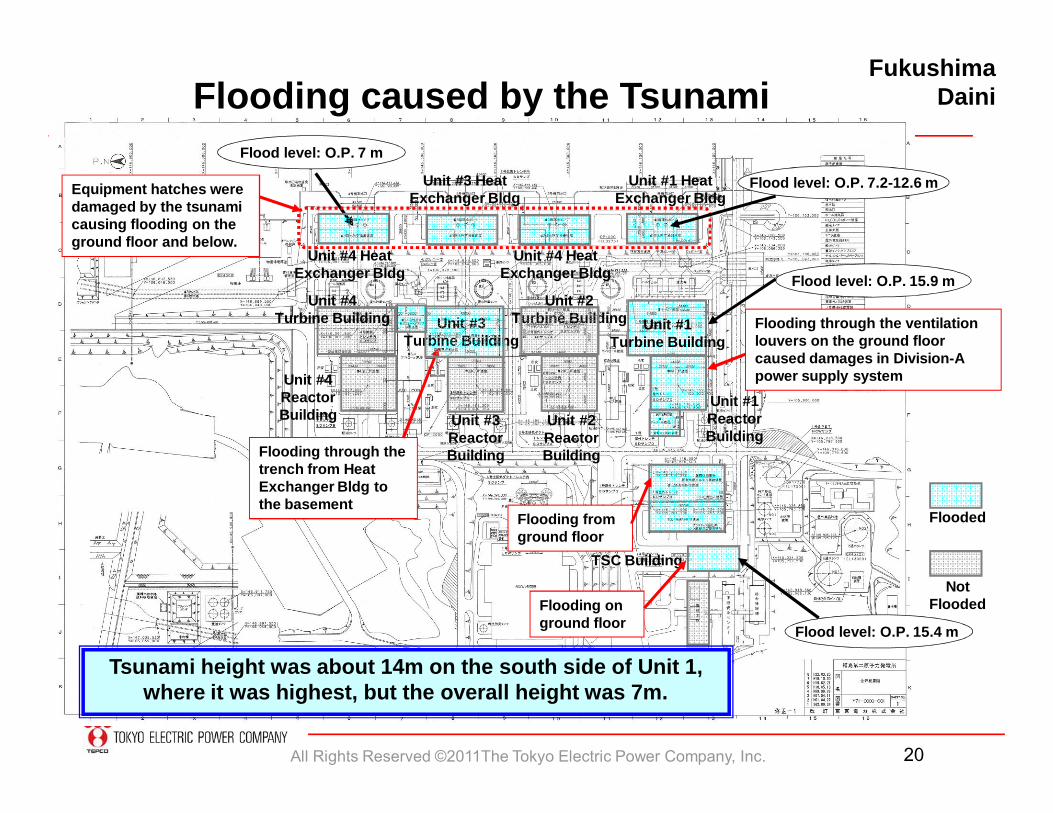
Fukushima Daini
Unit #1Reactor Building
Flooding through the ventilation louvers on the ground floor caused damages in Division-A power supply system
Flooding through the trench from Heat Exchanger Bldg to the basement
Unit #4Reactor Building
Unit #3Turbine Building
Unit #1Turbine Building
Unit #2Turbine Building
Flood level: O.P. 7 m
Unit #3 Heat Exchanger BldgEquipment hatches were
damaged by the tsunami causing flooding on the ground floor and below.
Flood level: O.P. 7.2-12.6 mUnit #1 Heat Exchanger Bldg
Unit #4 Heat Exchanger Bldg
Unit #4 Heat Exchanger Bldg
Unit #4Turbine Building
Unit #2Reactor Building
Unit #3Reactor Building
TSC Building
Flooding from ground floor
Flooding on ground floor
Flooded
Not Flooded
Flood level: O.P. 15.9 m
Flood level: O.P. 15.4 m
Tsunami height was about 14m on the south side of Unit 1, where it was highest, but the overall height was 7m.
Flooding caused by the Tsunami
All Rights Reserved ©2011The Tokyo Electric Power Company, Inc. 21
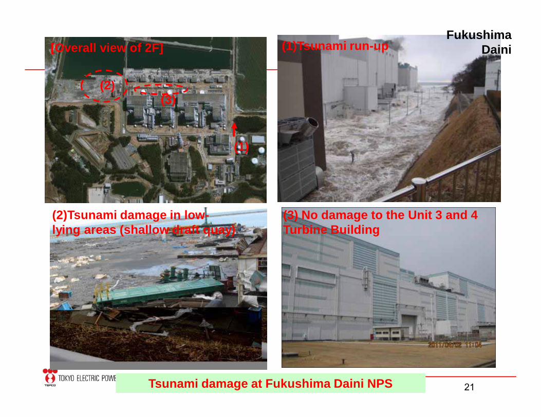
[Overall view of 2F]
(1)
(2)(3)
(1)Tsunami run-up
(2)Tsunami damage in low-lying areas (shallow draft quay)
(3) No damage to the Unit 3 and 4 Turbine Building
Fukushima Daini
Tsunami damage at Fukushima Daini NPS
All Rights Reserved ©2011The Tokyo Electric Power Company, Inc. 22
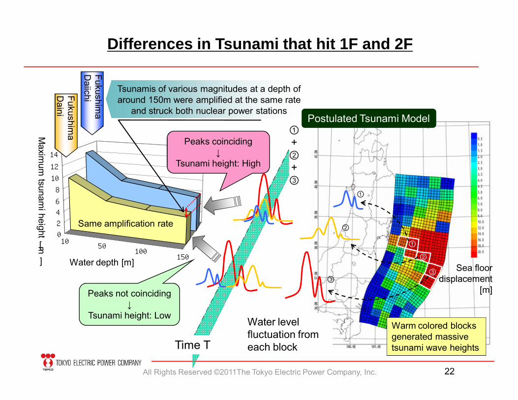
Differences in Tsunami that hit 1F and 2F
1050
100150
福島第二
福島第一0
2
4
6
8
10
12
14
水深[m ] Sea floordisplacement
[m]
Fukushima
DaiichiFukushim
a D
aini
Maxim
um tsunam
i height
[m
]
Peaks coinciding↓
Tsunami height: High
Peaks not coinciding↓
Tsunami height: Low
①②
③
Same amplification rate
Water level fluctuation from each blockTime T
Warm colored blocks generated massive tsunami wave heights
③
②
①
Tsunamis of various magnitudes at a depth of around 150m were amplified at the same rate
and struck both nuclear power stations
Water depth [m]
①+②+③
Postulated Tsunami Model
All Rights Reserved ©2011The Tokyo Electric Power Company, Inc. 23
Ohkuma 4L
大熊線2L
4A4B
4D 4C
4E
D/G4B
D/G4A
D/G3B
D/G3A D/G
2B
D/G2A
D/G1B
D/G1A
3A3B
3C3D
3SA3SB
2A2B
2C2D
2E
2SA2SB
1A1B
1C1D
1S
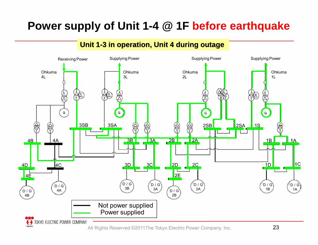
Unit 1Unit 1--3 in operation, Unit 4 during outage 3 in operation, Unit 4 during outage
Supplying PowerReceiving Power
Power supply of Unit 1-4 @ 1F before earthquake
Not power suppliedPower supplied
Ohkuma 3L
Supplying Power Supplying Power
Ohkuma 2L
Ohkuma 1L
All Rights Reserved ©2011The Tokyo Electric Power Company, Inc. 24
4A4B
4D 4C
4E
D/G
4B
D/G
4A
D/G
3B
D/G
3AD/G
2B
D/G
2A
D/G
1B
D/G
1A
3A3B
3C3D
3SA3SB
2A2B
2C2D
2E
2SA2SB
1A1B
1C1D
1S
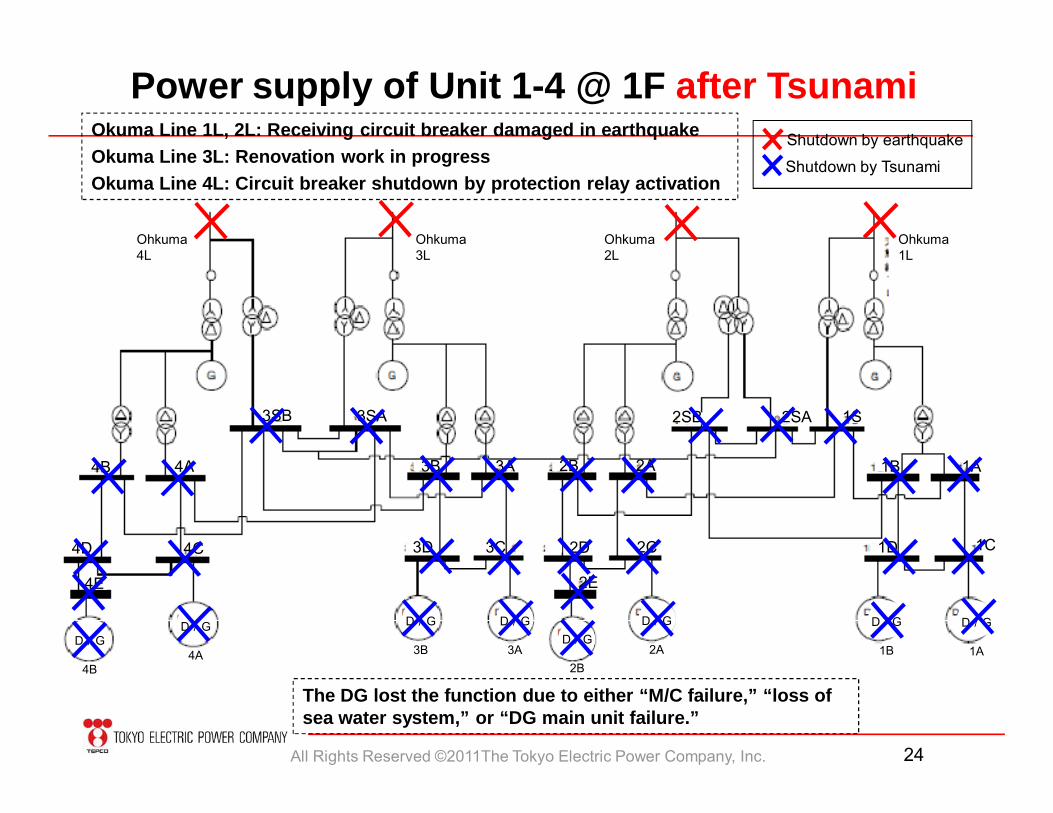
Shutdown by earthquake
Shutdown by Tsunami
Power supply of Unit 1-4 @ 1F after Tsunami
The DG lost the function due to either “M/C failure,” “loss of sea water system,” or “DG main unit failure.”
Okuma Line 1L, 2L: Receiving circuit breaker damaged in earthquakeOkuma Line 3L: Renovation work in progressOkuma Line 4L: Circuit breaker shutdown by protection relay activation
Ohkuma 4L
Ohkuma 3L
Ohkuma 2L
Ohkuma 1L
All Rights Reserved ©2011The Tokyo Electric Power Company, Inc. 25
Futaba 2L
Yonomori 2L
5A
5C
5B
5D
D/G5A
D/G5B
D/GHPCS
D/G6A
D/G6B
5SA-1 5SA-2 5SB-25SB-1 6A-1 6A-2
HPCS 6C
6B-1 6B-2
6D
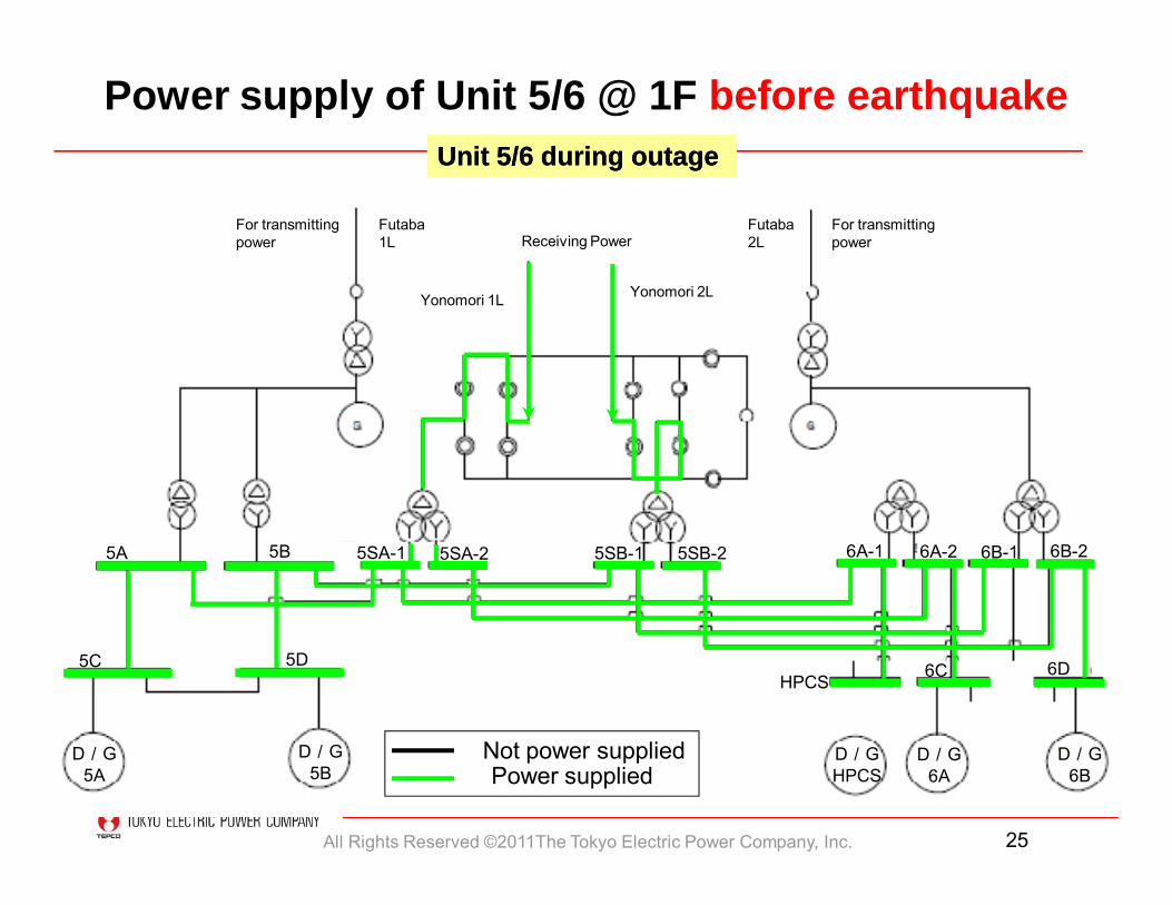
For transmitting power
Not power suppliedPower supplied
Power supply of Unit 5/6 @ 1F before earthquakeUnit 5/6 during outage Unit 5/6 during outage
Receiving PowerFutaba 1L
For transmitting power
Yonomori 1L
All Rights Reserved ©2011The Tokyo Electric Power Company, Inc. 26
双葉線1L
双葉線2L
5A
5C
5B
5D
D/G
5A
D/G
5B
D/G
HPCS
D/G
6A
D/G6B
5SA-1 5SA-2 5SB-25SB-1 6A-1 6A-2
HPCS 6C
6B-1 6B-2
6D
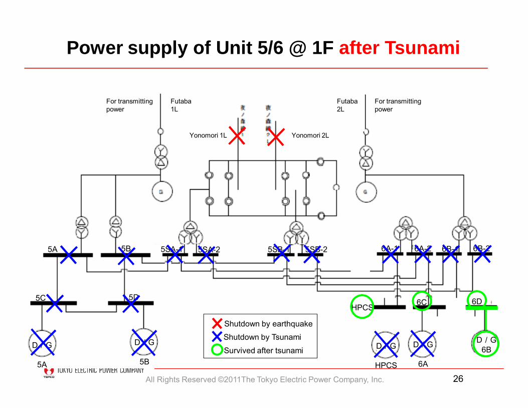
Shutdown by earthquakeShutdown by Tsunami
Survived after tsunami
Power supply of Unit 5/6 @ 1F after Tsunami
Futaba 1L
Futaba 2L
Yonomori 2LYonomori 1L
For transmitting power
For transmitting power
All Rights Reserved ©2011The Tokyo Electric Power Company, Inc. 27
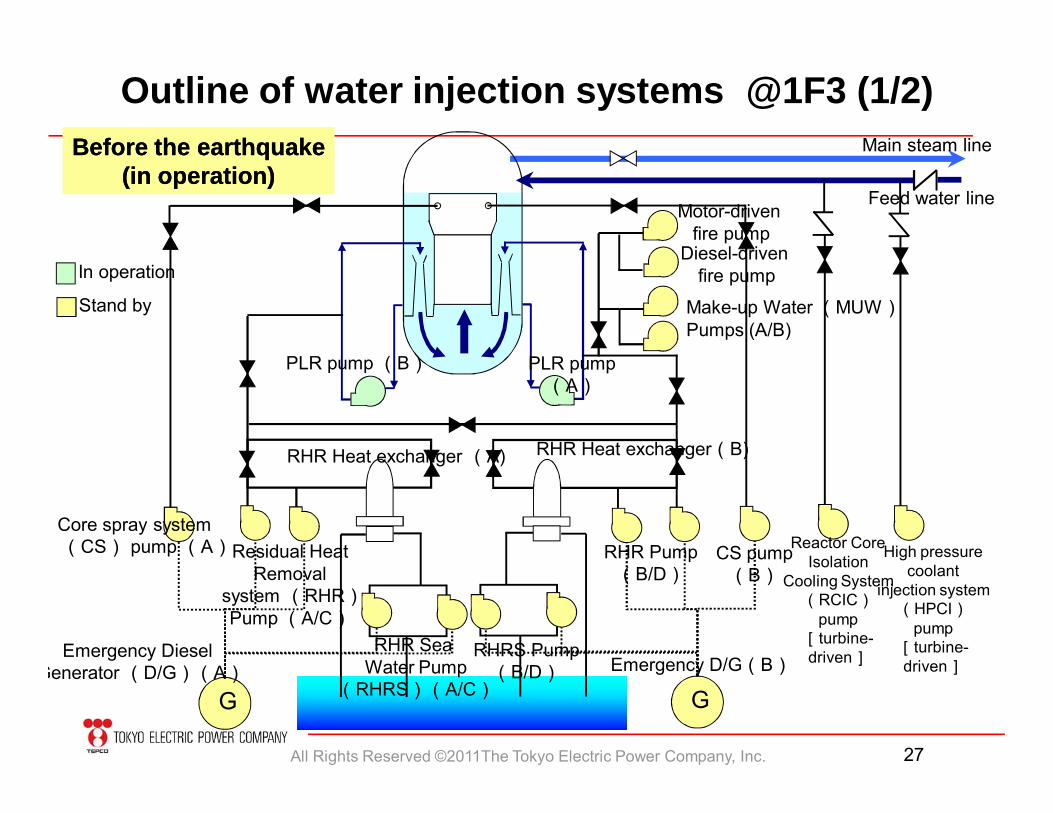
Main steam line
High pressure coolant
injection system (HPCI)
pump[turbine-driven]
CS pump(B)
RHR Pump(B/D)
Core spray system(CS) pump (A)Residual Heat
Removalsystem (RHR)Pump (A/C)
RHRS Pump(B/D)
RHR Sea Water Pump
(RHRS)(A/C)
RHR Heat exchanger (A) RHR Heat exchanger(B)
PLR pump (B) PLR pump(A)
Before the earthquakeBefore the earthquake(in operation)(in operation)
G
In operation
Stand by
Emergency Diesel Generator (D/G)(A)
GEmergency D/G(B)
Reactor Core Isolation
Cooling System (RCIC)
pump[turbine-driven]
Outline of water injection systems @1F3 (1/2)
Feed water line
Make-up Water (MUW)Pumps (A/B)
Motor-drivenfire pump
Diesel-drivenfire pump
All Rights Reserved ©2011The Tokyo Electric Power Company, Inc. 28
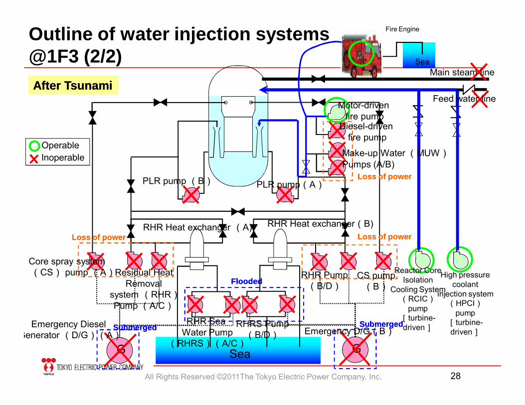
Fire Engine
G G
After TsunamiAfter Tsunami
Loss of powerLoss of power
SubmergedSubmerged
FloodedFlooded
OperableInoperable
Sea
Sea
Outline of water injection systems @1F3 (2/2)
Main steam line
Feed water line
PLR pump (B) PLR pump(A)
Make-up Water (MUW)Pumps (A/B)
Motor-drivenfire pump
Diesel-drivenfire pump
High pressure coolant
injection system (HPCI)
pump[turbine-driven]
CS pump(B)
RHR Pump(B/D)
Core spray system(CS) pump (A)Residual Heat
Removalsystem (RHR)Pump (A/C)
RHRS Pump(B/D)
RHR Sea Water Pump
(RHRS)(A/C)
RHR Heat exchanger (A) RHR Heat exchanger(B)
Emergency Diesel Generator (D/G)(A) Emergency D/G(B)
Reactor Core Isolation
Cooling System (RCIC)
pump[turbine-driven]
Loss of powerLoss of power
Loss of powerLoss of power
SubmergedSubmerged
All Rights Reserved ©2011The Tokyo Electric Power Company, Inc. 29
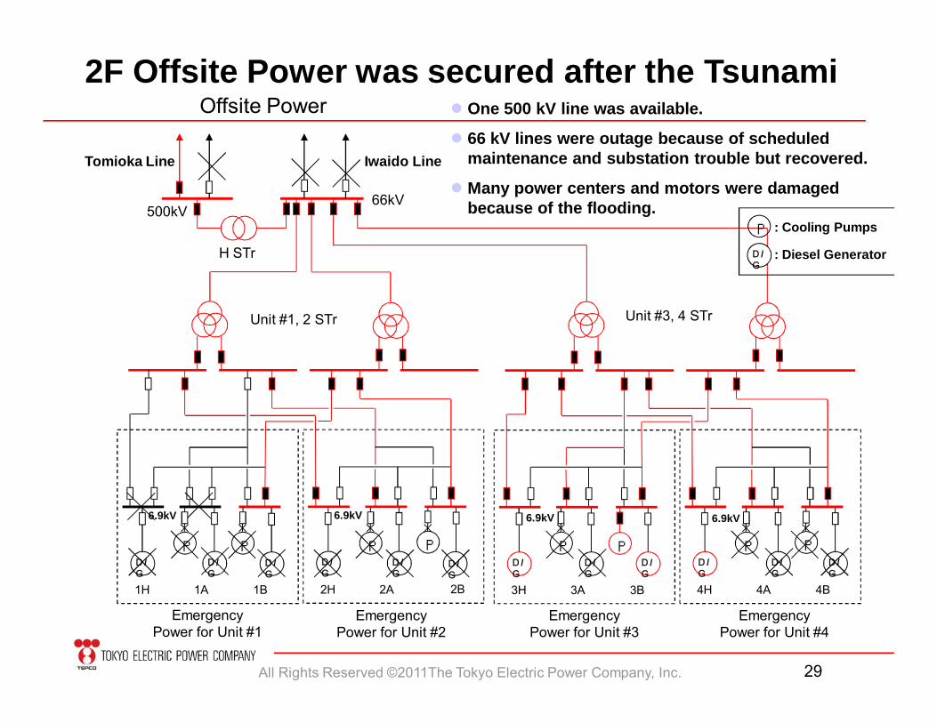
6.9kV 6.9kV
2F Offsite Power was secured after the TsunamiOffsite Power
500kV66kV
H STr
Unit #1, 2 STr Unit #3, 4 STr
D/G
Emergency Power for Unit #1
D/G
1H 1A 1B
6.9kV
D/G
D/G
2H 2A 2B
D/G
3H 3A 3B
6.9kV
D/G
D/G
4H 4A 4B
One 500 kV line was available.
66 kV lines were outage because of scheduled maintenance and substation trouble but recovered.
Many power centers and motors were damaged because of the flooding.
PPPP
Emergency Power for Unit #2
Emergency Power for Unit #3
Emergency Power for Unit #4
D/G
P : Cooling Pumps
D/G
: Diesel Generator
D/G
PD/G
PD/G
PD/G
P
Tomioka Line Iwaido Line
All Rights Reserved ©2011The Tokyo Electric Power Company, Inc. 30
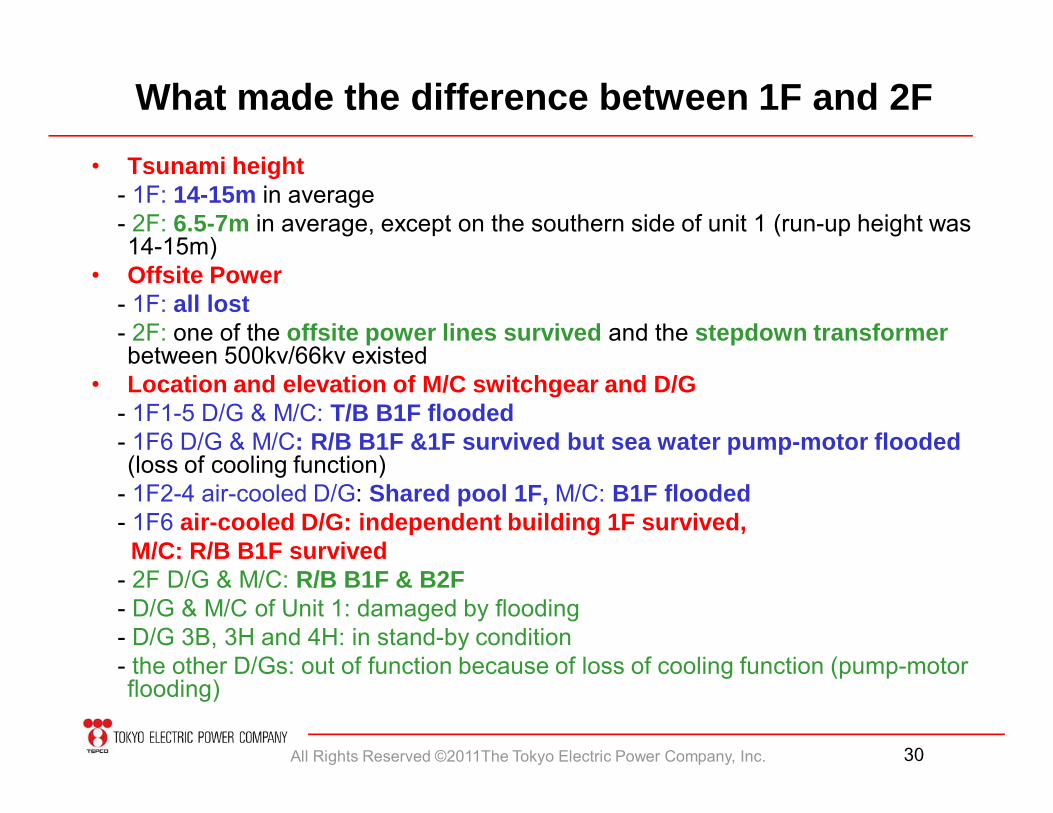
What made the difference between 1F and 2F• Tsunami height
- 1F: 14-15m in average- 2F: 6.5-7m in average, except on the southern side of unit 1 (run-up height was 14-15m)
• Offsite Power- 1F: all lost- 2F: one of the offsite power lines survived and the stepdown transformerbetween 500kv/66kv existed
• Location and elevation of M/C switchgear and D/G- 1F1-5 D/G & M/C: T/B B1F flooded- 1F6 D/G & M/C: R/B B1F &1F survived but sea water pump-motor flooded (loss of cooling function)
- 1F2-4 air-cooled D/G: Shared pool 1F, M/C: B1F flooded- 1F6 air-cooled D/G: independent building 1F survived,
M/C: R/B B1F survived- 2F D/G & M/C: R/B B1F & B2F- D/G & M/C of Unit 1: damaged by flooding- D/G 3B, 3H and 4H: in stand-by condition- the other D/Gs: out of function because of loss of cooling function (pump-motor flooding)
All Rights Reserved ©2011The Tokyo Electric Power Company, Inc. 31
3. How we responded ?
- What difficulties existed- What were effectively utilized
All Rights Reserved ©2011The Tokyo Electric Power Company, Inc. 32
Fukushima Daiichi Units 1 - 4 Fukushima Daiichi Units 5 & 6 Fukushima Daini Units 1 - 4
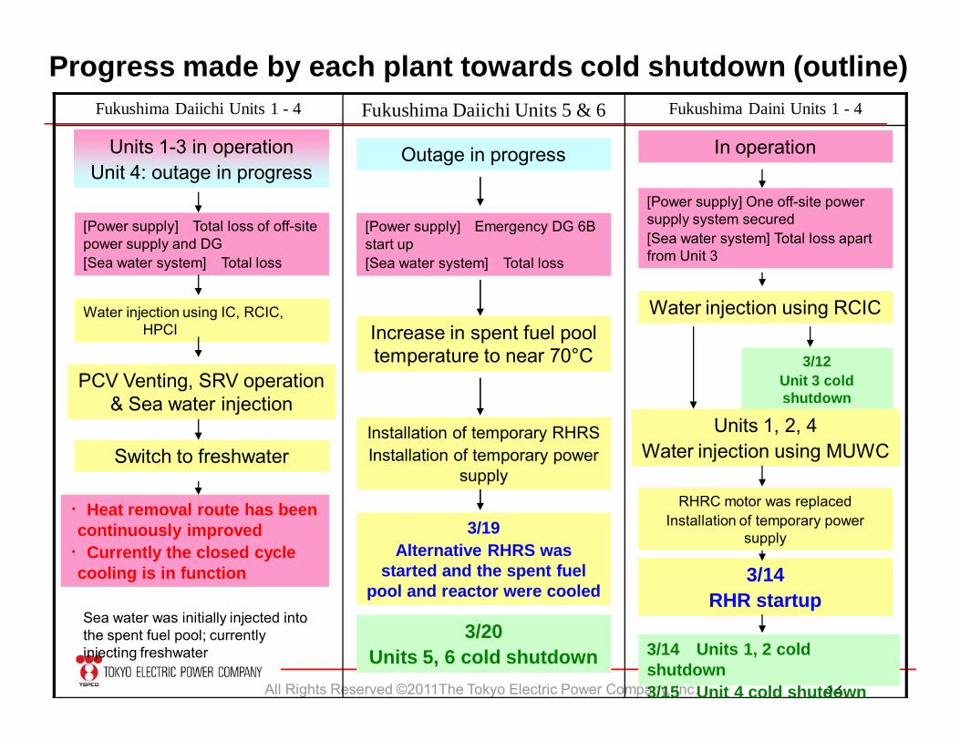
Progress made by each plant towards cold shutdown (outline)
Units 1-3 in operationUnit 4: outage in progress
[Power supply] Total loss of off-site power supply and DG[Sea water system] Total loss
Water injection using IC, RCIC, HPCI
PCV Venting, SRV operation & Sea water injection
Switch to freshwater
・Heat removal route has been continuously improved
・Currently the closed cycle cooling is in function
Sea water was initially injected into the spent fuel pool; currently injecting freshwater
Outage in progress
[Power supply] Emergency DG 6B start up[Sea water system] Total loss
3/19Alternative RHRS was
started and the spent fuel pool and reactor were cooled
Increase in spent fuel pool temperature to near 70°C
3/20Units 5, 6 cold shutdown
Installation of temporary RHRSInstallation of temporary power
supply
In operation
[Power supply] One off-site power supply system secured[Sea water system] Total loss apart from Unit 3
3/12Unit 3 cold shutdown
Units 1, 2, 4Water injection using MUWC
3/14RHR startup
Water injection using RCIC
3/14 Units 1, 2 cold shutdown3/15 Unit 4 cold shutdown
RHRC motor was replacedInstallation of temporary power
supply
All Rights Reserved ©2011The Tokyo Electric Power Company, Inc. 33
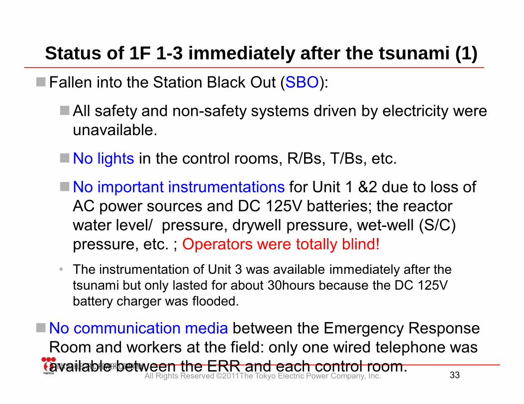
Status of 1F 1-3 immediately after the tsunami (1) Fallen into the Station Black Out (SBO):
All safety and non-safety systems driven by electricity were unavailable.
No lights in the control rooms, R/Bs, T/Bs, etc.
No important instrumentations for Unit 1 &2 due to loss of AC power sources and DC 125V batteries; the reactor water level/ pressure, drywell pressure, wet-well (S/C) pressure, etc. ; Operators were totally blind!
• The instrumentation of Unit 3 was available immediately after the tsunami but only lasted for about 30hours because the DC 125V battery charger was flooded.
No communication media between the Emergency Response Room and workers at the field: only one wired telephone was available between the ERR and each control room.
All Rights Reserved ©2011The Tokyo Electric Power Company, Inc. 34
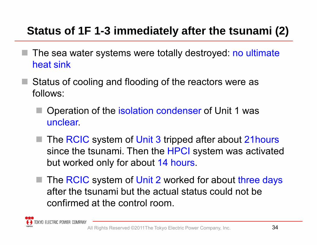
Status of 1F 1-3 immediately after the tsunami (2)
The sea water systems were totally destroyed: no ultimate heat sink
Status of cooling and flooding of the reactors were as follows:
Operation of the isolation condenser of Unit 1 was unclear.
The RCIC system of Unit 3 tripped after about 21hourssince the tsunami. Then the HPCI system was activated but worked only for about 14 hours.
The RCIC system of Unit 2 worked for about three daysafter the tsunami but the actual status could not be confirmed at the control room.
All Rights Reserved ©2011The Tokyo Electric Power Company, Inc. 35
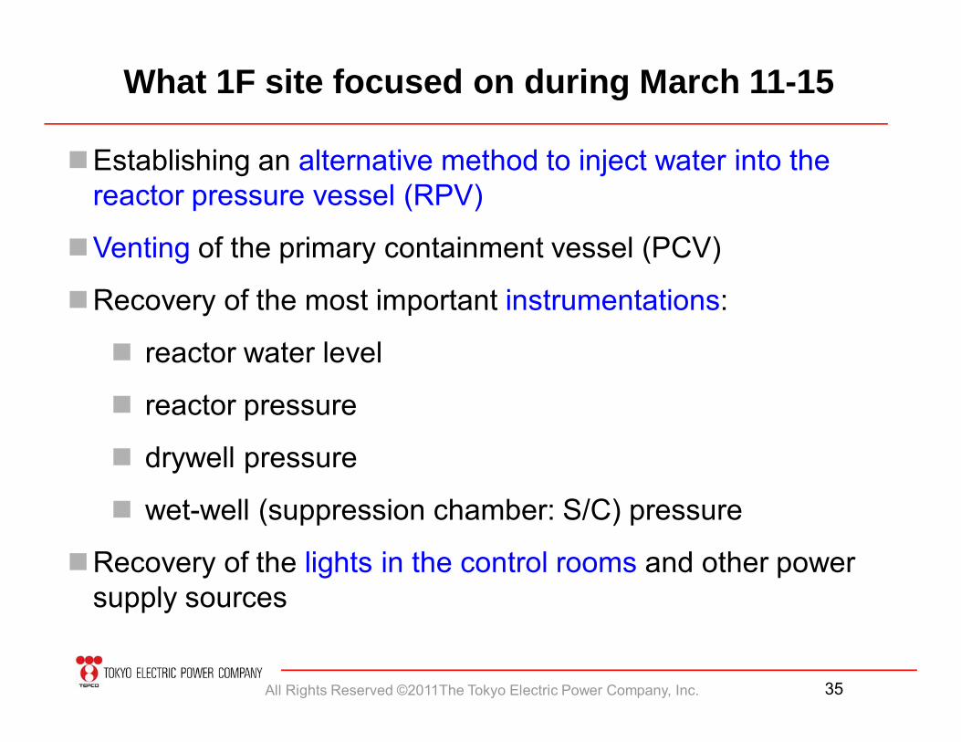
Establishing an alternative method to inject water into the reactor pressure vessel (RPV)
Venting of the primary containment vessel (PCV)
Recovery of the most important instrumentations:
reactor water level
reactor pressure
drywell pressure
wet-well (suppression chamber: S/C) pressure
Recovery of the lights in the control rooms and other power supply sources
What 1F site focused on during March 11-15
All Rights Reserved ©2011The Tokyo Electric Power Company, Inc. 36
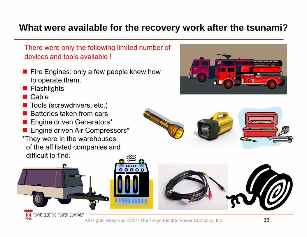
What were available for the recovery work after the tsunami?
There were only the following limited number of devices and tools available !
Fire Engines: only a few people knew howto operate them.
Flashlights Cable Tools (screwdrivers, etc.) Batteries taken from cars Engine driven Generators* Engine driven Air Compressors**They were in the warehouses of the affiliated companies anddifficult to find.
All Rights Reserved ©2011The Tokyo Electric Power Company, Inc. 37
Human Resource Issues after the Tsunami @1F
• After the tsunami, approximately 400 people (about 130 for operation, about 270 for maintenance) were available for the recovery process.
• The number of the operations personnel was totally insufficient for the recovery operation of six units.
• About 70 TEPCO employees (maintenance) and about 40 people from affiliated companies were engaged in the initial field work to recover Unit 1-3; most of the work was recovery of instrumentations and power supply.
• Number of electric and I&C maintenance personnel was also insufficient.
• High radiation dose made the above human resource problem more serious.
All Rights Reserved ©2011The Tokyo Electric Power Company, Inc. 38
Alternative water injection into the reactors @1F
1. Tried to inject fresh water using the diesel driven fire protection pump (DDFP): failed. Unit 1: mechanical problem of the DDFP Unit 2: the DDFP was flooded Unit 3: the RPV pressure was too high
2. Injection of fresh water from underground water tank(16units/site×40m3/site) using the fire engine pumps : succeeded but did not last for long time due to insufficient water supply.
3. Injection of sea water using the fire engine pump. Hurdles for the work:
Suspensions due to aftershocks and tsunami alarms Damages of the fresh water lines due to the earthquake Debris and damages of the gates caused by the tsunami Hydrogen explosions (rubble, damage of fire engines and other
devices, injury of field workers and fear of another explosion) No lights. Problem with the PHS telephone and radio communication
All Rights Reserved ©2011The Tokyo Electric Power Company, Inc. 39
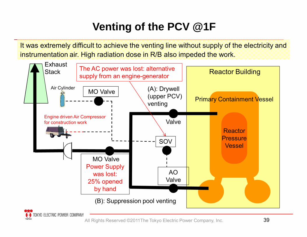
(B): Suppression pool venting
Primary Containment Vessel
ReactorPressure Vessel
Venting of the PCV @1F
Exhaust Stack Reactor Building
MO ValvePower Supply
was lost: 25% opened
by hand
AO Valve
It was extremely difficult to achieve the venting line without supply of the electricity and instrumentation air. High radiation dose in R/B also impeded the work.
(A): Drywell (upper PCV) venting
SOV
The AC power was lost: alternative supply from an engine-generator
MO Valve Air Cylinder
Engine driven Air Compressorfor construction work Valve
All Rights Reserved ©2011The Tokyo Electric Power Company, Inc. 40
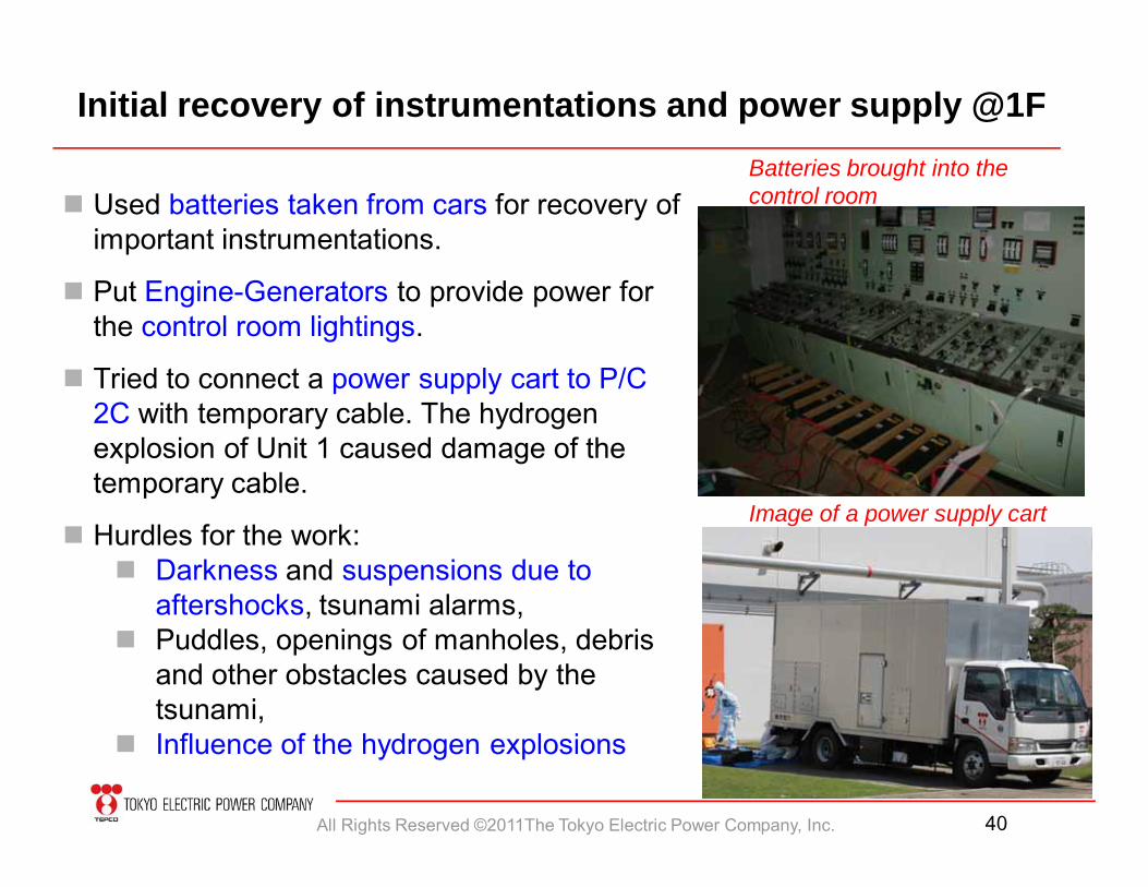
Initial recovery of instrumentations and power supply @1F
Image of a power supply cart
Used batteries taken from cars for recovery of important instrumentations.
Put Engine-Generators to provide power for the control room lightings.
Tried to connect a power supply cart to P/C 2C with temporary cable. The hydrogen explosion of Unit 1 caused damage of the temporary cable.
Hurdles for the work: Darkness and suspensions due to
aftershocks, tsunami alarms, Puddles, openings of manholes, debris
and other obstacles caused by the tsunami,
Influence of the hydrogen explosions
Batteries brought into the control room
All Rights Reserved ©2011The Tokyo Electric Power Company, Inc. 41
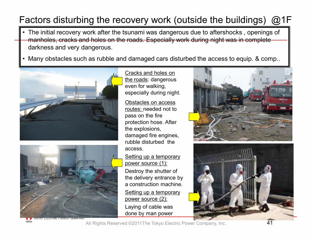
Factors disturbing the recovery work (outside the buildings) @1F• The initial recovery work after the tsunami was dangerous due to aftershocks , openings of
manholes, cracks and holes on the roads. Especially work during night was in complete darkness and very dangerous.
• Many obstacles such as rubble and damaged cars disturbed the access to equip. & comp..
Cracks and holes on the roads: dangerous even for walking, especially during night.
Obstacles on access routes: needed not to pass on the fire protection hose. After the explosions, damaged fire engines, rubble disturbed the access.Setting up a temporary power source (1):Destroy the shutter of the delivery entrance by a construction machine. Setting up a temporary power source (2):Laying of cable was done by man power
All Rights Reserved ©2011The Tokyo Electric Power Company, Inc. 42
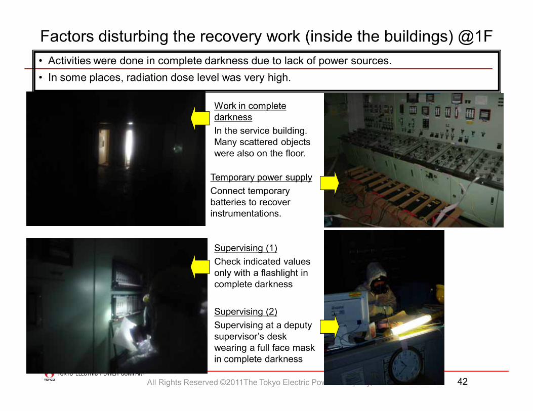
• Activities were done in complete darkness due to lack of power sources.• In some places, radiation dose level was very high.
Work in complete darknessIn the service building.Many scattered objects were also on the floor.
Temporary power supplyConnect temporary batteries to recover instrumentations.
Supervising (1)Check indicated values only with a flashlight in complete darkness
Factors disturbing the recovery work (inside the buildings) @1F
Supervising (2)Supervising at a deputy supervisor’s desk wearing a full face mask in complete darkness
All Rights Reserved ©2011The Tokyo Electric Power Company, Inc. 43
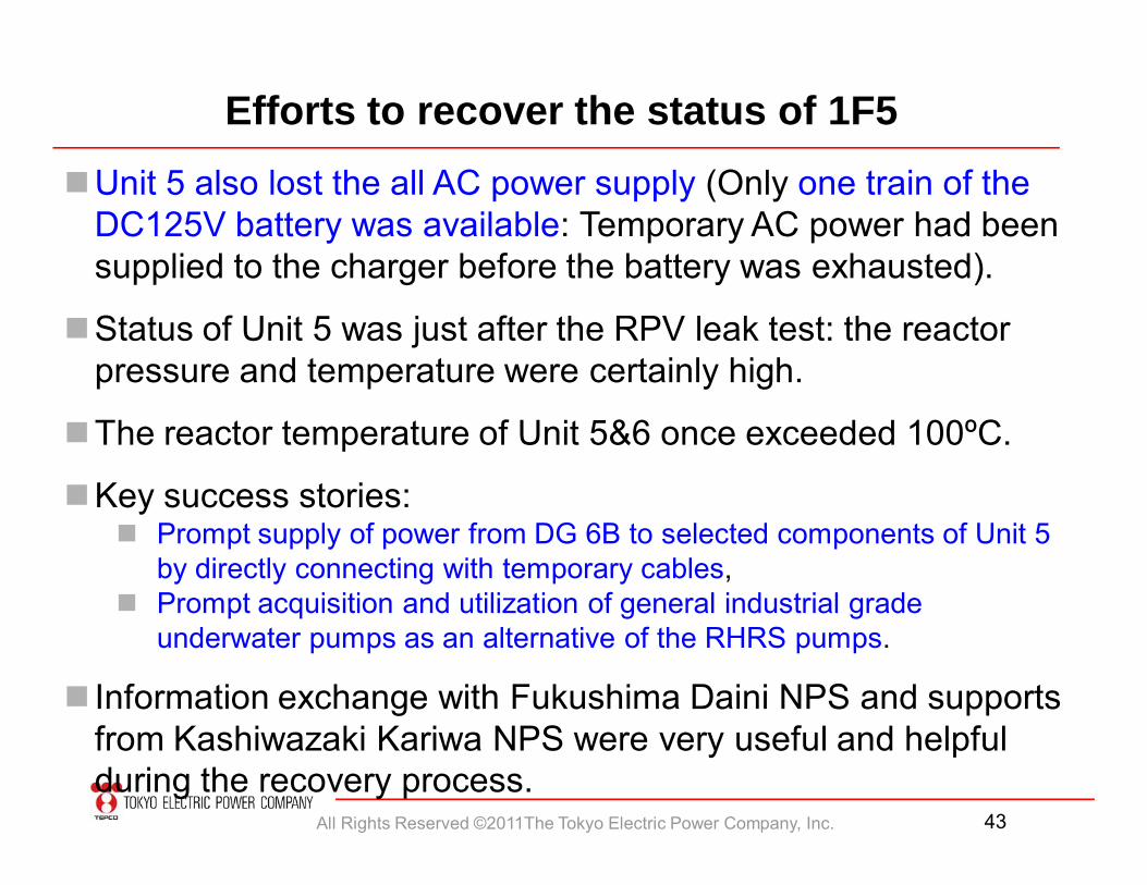
Efforts to recover the status of 1F5Unit 5 also lost the all AC power supply (Only one train of the
DC125V battery was available: Temporary AC power had been supplied to the charger before the battery was exhausted).
Status of Unit 5 was just after the RPV leak test: the reactor pressure and temperature were certainly high.
The reactor temperature of Unit 5&6 once exceeded 100ºC.
Key success stories: Prompt supply of power from DG 6B to selected components of Unit 5
by directly connecting with temporary cables, Prompt acquisition and utilization of general industrial grade
underwater pumps as an alternative of the RHRS pumps.
Information exchange with Fukushima Daini NPS and supports from Kashiwazaki Kariwa NPS were very useful and helpful during the recovery process.
All Rights Reserved ©2011The Tokyo Electric Power Company, Inc. 44
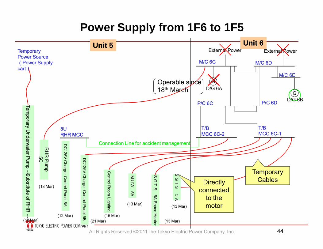
Power Supply from 1F6 to 1F5Unit 5Unit 5 Unit 6Unit 6
Temporary U
nderwater Pum
p
(Substitute of RH
R
)
RH
R Pum
p5C
5U5URHR MCCRHR MCC
TemporaryTemporaryPower Source Power Source ((Power Supply Power Supply cartcart))
(18 Mar)
(18 Mar)
T/BT/BMCC 6CMCC 6C--22
Control R
oom Lighting
MU
W5A
SG
TS
5A
5U5URHR MCCRHR MCC
Connection Line for accident managementConnection Line for accident managementDC
125V C
harger Control P
anel 5A
SG
TS
5A S
pace Heater(21 Mar)
(12 Mar) (15 Mar)
(13 Mar)
(13 Mar)
(13 Mar)
Directly connected
to the motor
Temporary Cables
DC
125V C
harger Control P
anel 5B
T/BT/BMCC 6CMCC 6C--11
M/C 6EM/C 6E
M/C 6CM/C 6C
GD/G 6A
External Power External Power
P/C 6DP/C 6DP/C 6CP/C 6C
Operable since 18th March
D/G 6B
M/C 6DM/C 6D
G
All Rights Reserved ©2011The Tokyo Electric Power Company, Inc. 45
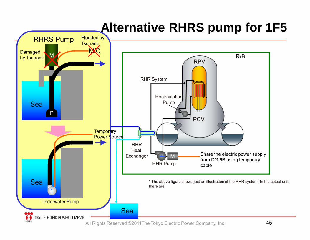
PCV
RHR System
RecirculationPump
R/B
RHR Pump
RHRHeat
Exchanger
RPV
* The above figure shows just an illustration of the RHR system. In the actual unit, there are
Alternative RHRS pump for 1F5
M Share the electric power supplyfrom DG 6B using temporary cable
Sea
M
Sea
Damaged by Tsunami
P
Sea
Underwater Pump
Temporary Power Source
M/C
RHRS Pump Flooded byTsunami
All Rights Reserved ©2011The Tokyo Electric Power Company, Inc. 46
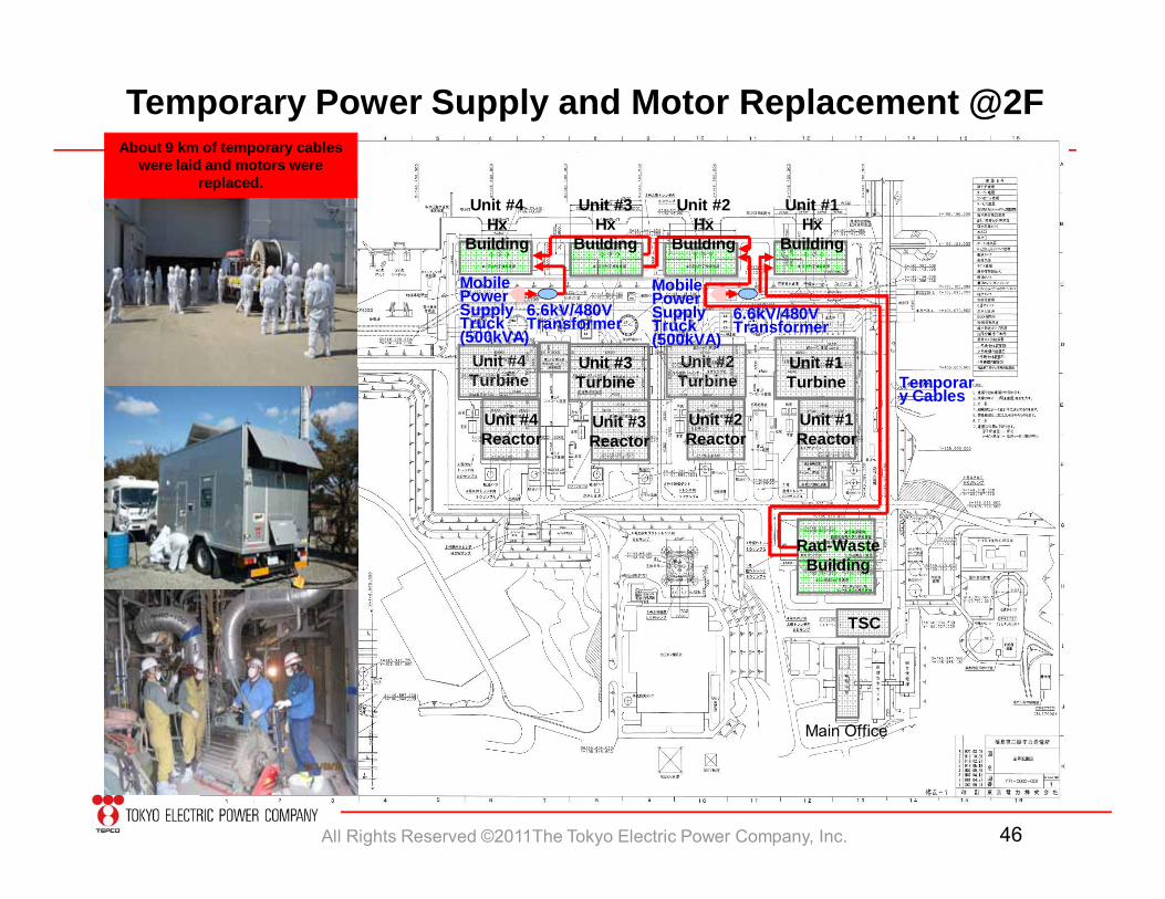
Temporary Power Supply and Motor Replacement @2F
Unit #3Hx
Building
Unit #1Reactor
Rad-WasteBuilding
TSC
Main Office
Unit #4Turbine
Unit #2Hx
Building
Unit #1Hx
Building
Unit #4Hx
Building
Unit #2Reactor
Unit #3Reactor
Unit #4Reactor
Unit #3Turbine
Unit #1Turbine
Unit #2Turbine
MobilePowerSupplyTruck (500kVA)
Temporary Cables
MobilePowerSupplyTruck (500kVA)
6.6kV/480VTransformer 6.6kV/480V
Transformer
About 9 km of temporary cables were laid and motors were
replaced.
All Rights Reserved ©2011The Tokyo Electric Power Company, Inc. 47
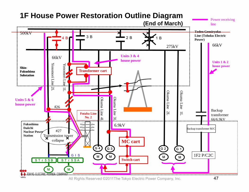
1F House Power Restoration Outline Diagram (End of March)
3B 2B500kV
275kV
G1
Okum
a Line 2L
Shin-Fukushima Substation
G2
M
×
×
× Toden GensiryokuLine (Tohoku Electric Power)
Units 1 & 2 house power
Power receiving line
Backup transformer M/C
1F2 P/C2C
Backup transformer 66/6.9kV
66kV
Okum
a Line 1L
M
1B4B
66kV
Yonomori Line 2L
Shin-Fukushima Substation
Units 5 & 6 house power
Yonomori Line 1L
Transformer cart
Units 3 & 4 house power
#27Transmission tower
collapse × ×
Fukushima Daiichi Nuclear Power Station
Futaba Line No. 2
M M
STr5SB STr5SA
♯26
Switch cart
MC cart G3G4
MMGIS
Okum
a Line 4L
6.9kV
Okum
a Line 3L
All Rights Reserved ©2011The Tokyo Electric Power Company, Inc. 48
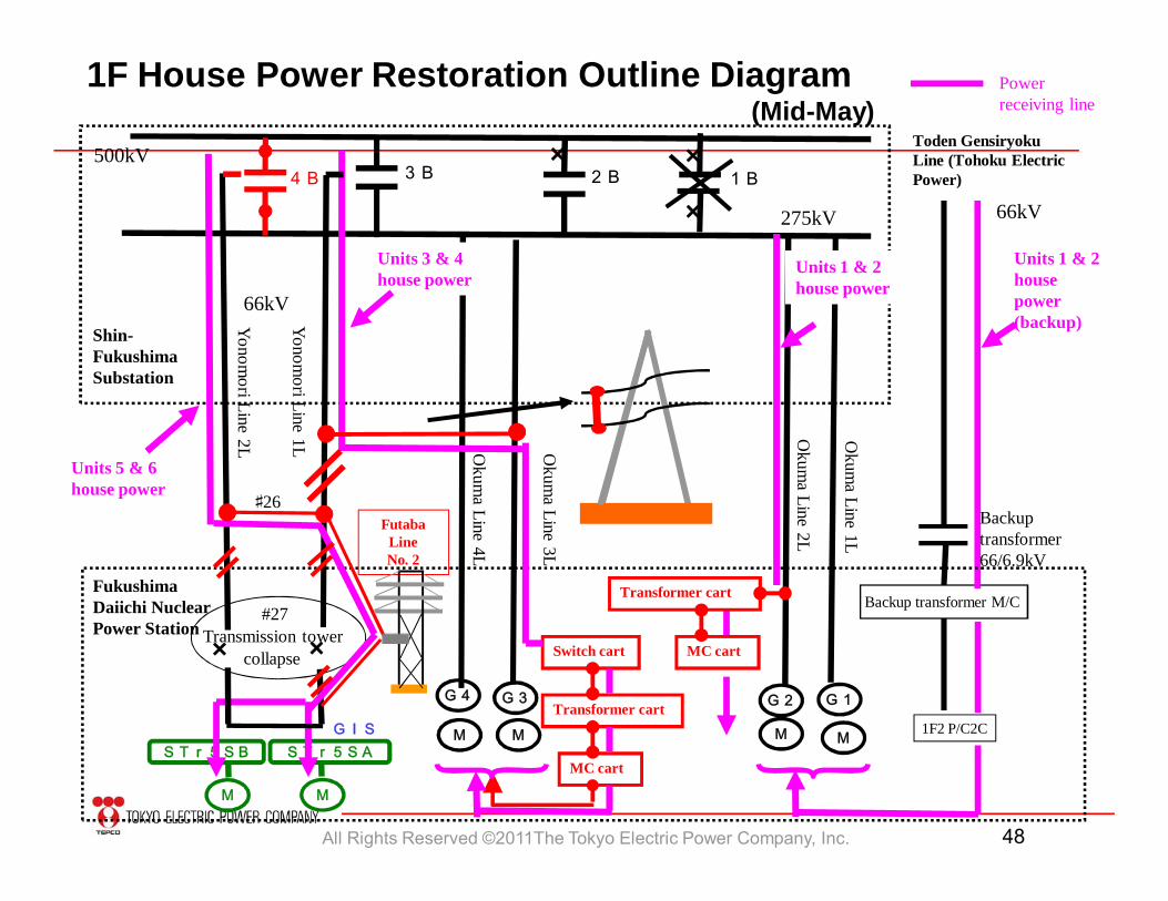
1F House Power Restoration Outline Diagram (Mid-May)
Toden Gensiryoku Line (Tohoku Electric Power)
Units 1 & 2 house power (backup)
Power receiving line
Backup transformer M/C
1F2 P/C2C
66kV
4B 3B500kV
275kV
66kV
G1
Yonomori Line 2L O
kuma Line 4L
Shin-Fukushima Substation
Fukushima Daiichi Nuclear Power Station
G2G3G4
MM M M
M M
STr5SB STr5SA
×
×
×
GIS
Units 3 & 4 house power
Okum
a Line 3L
Yonomori Line 1L
#27Transmission tower
collapse × ×
♯26
Transformer cart
Switch cart
MC cart
2B 1B
Backup transformer 66/6.9kV
Okum
a Line 2L
Units 1 & 2 house power
Okum
a Line 1L
Transformer cart
MC cart
Units 5 & 6 house power
Futaba Line No. 2
All Rights Reserved ©2011The Tokyo Electric Power Company, Inc. 49
4. Current Status and Roadmap
All Rights Reserved ©2011The Tokyo Electric Power Company, Inc. 50
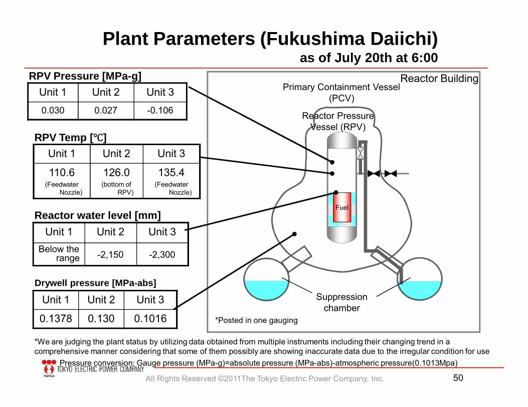
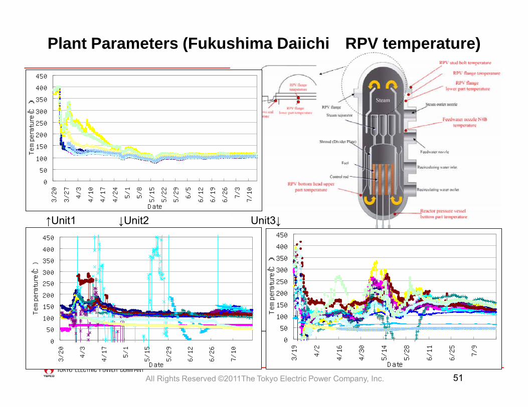
Plant Parameters (Fukushima Daiichi) as of July 20th at 6:00
Unit 1 Unit 2 Unit 3
0.1378 0.130 0.1016
Fuel
Suppression chamber
Primary Containment Vessel (PCV)
Reactor Pressure Vessel (RPV)
Drywell pressure [MPa-abs]
Reactor water level [mm]Unit 1 Unit 2 Unit 3
Below the range -2,150 -2,300
RPV Pressure [MPa-g]Unit 1 Unit 2 Unit 30.030 0.027 -0.106
Reactor Building
RPV Temp [ ]Unit 1 Unit 2 Unit 3
110.6(Feedwater
Nozzle)
126.0(bottom of
RPV)
135.4(Feedwater
Nozzle)
Pressure conversion: Gauge pressure (MPa-g)=absolute pressure (MPa-abs)-atmospheric pressure(0.1013Mpa)
*Posted in one gauging
*We are judging the plant status by utilizing data obtained from multiple instruments including their changing trend in a comprehensive manner considering that some of them possibly are showing inaccurate data due to the irregular condition for use
All Rights Reserved ©2011The Tokyo Electric Power Company, Inc. 51
←Unit2
Unit3→0
50
100
150
200
250
300
350
400
450
3/19
4/2
4/16
4/30
5/14
5/28
6/11
6/25
7/9
D ate
Temperature(℃)
0
50
100
150
200
250
300
350
400
450
3/20
4/3
4/17
5/1
5/15
5/29
6/12
6/26
7/10
D ate
Temperature(℃)
0
50
100
150
200
250
300
350
400
450
3/20
3/27
4/3
4/10
4/17
4/24
5/1
5/8
5/15
5/22
5/29
6/5
6/12
6/19
6/26
7/3
7/10
D ate
Temperature(℃)
↑Unit1 ↓Unit2 Unit3↓
Plant Parameters (Fukushima Daiichi RPV temperature)
All Rights Reserved ©2011The Tokyo Electric Power Company, Inc. 52
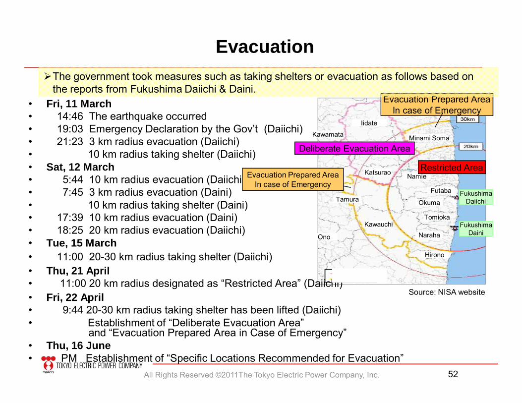
Evacuation
• Fri, 11 March• 14:46 The earthquake occurred• 19:03 Emergency Declaration by the Gov’t (Daiichi)• 21:23 3 km radius evacuation (Daiichi)• 10 km radius taking shelter (Daiichi)• Sat, 12 March• 5:44 10 km radius evacuation (Daiichi)• 7:45 3 km radius evacuation (Daini)• 10 km radius taking shelter (Daini)• 17:39 10 km radius evacuation (Daini)• 18:25 20 km radius evacuation (Daiichi)• Tue, 15 March• 11:00 20-30 km radius taking shelter (Daiichi)• Thu, 21 April• 11:00 20 km radius designated as “Restricted Area” (Daiichi)• Fri, 22 April• 9:44 20-30 km radius taking shelter has been lifted (Daiichi)• Establishment of “Deliberate Evacuation Area”
and “Evacuation Prepared Area in Case of Emergency”• Thu, 16 June• PM Establishment of “Specific Locations Recommended for Evacuation”
Minami Soma
Iidate
Kawamata
Katsurao Namie
Futaba
Okuma
Tomioka
Naraha
Hirono
Kawauchi
Ono
Tamura 福島第一
福島第二
Restricted Area
Deliberate Evacuation Area
Evacuation Prepared AreaIn case of Emergency
Source: NISA website
FukushimaDaiichi
FukushimaDaini
Evacuation Prepared AreaIn case of Emergency
The government took measures such as taking shelters or evacuation as follows based on the reports from Fukushima Daiichi & Daini.
All Rights Reserved ©2011The Tokyo Electric Power Company, Inc. 53
94
115
37
17
14
15
235
13 336
34
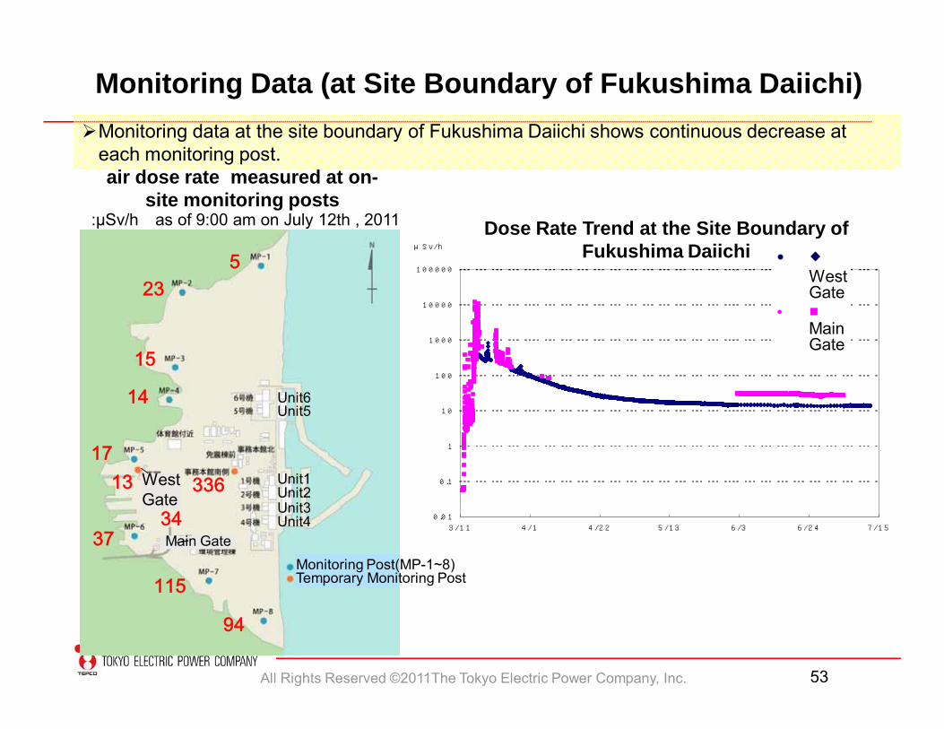
Monitoring Data (at Site Boundary of Fukushima Daiichi)
:μSv/h as of 9:00 am on July 12th , 2011 Dose Rate Trend at the Site Boundary of Fukushima Daiichi
Monitoring data at the site boundary of Fukushima Daiichi shows continuous decrease at each monitoring post.air dose rate measured at on-
site monitoring posts
WestGate
Main Gate
0 .0 1
0 .1
1
1 0
1 0 0
1 0 0 0
1 0 0 0 0
1 0 0 0 0 0
3 /1 1 4 /1 4 /2 2 5 /1 3 6 /3 6 /2 4 7 /1 5
西門
正門
μS v/h
• ◆West Gate
• ■Main Gate
Unit1Unit2Unit3Unit4
Monitoring Post(MP-1~8)Temporary Monitoring Post
Unit6Unit5
All Rights Reserved ©2011The Tokyo Electric Power Company, Inc. 54
③ ② ①③ ② ①
③’ ②’ ①’③’ ②’ ①’
RPV
To each unit
RPVRPVRPVtank
Unit 4
⑤
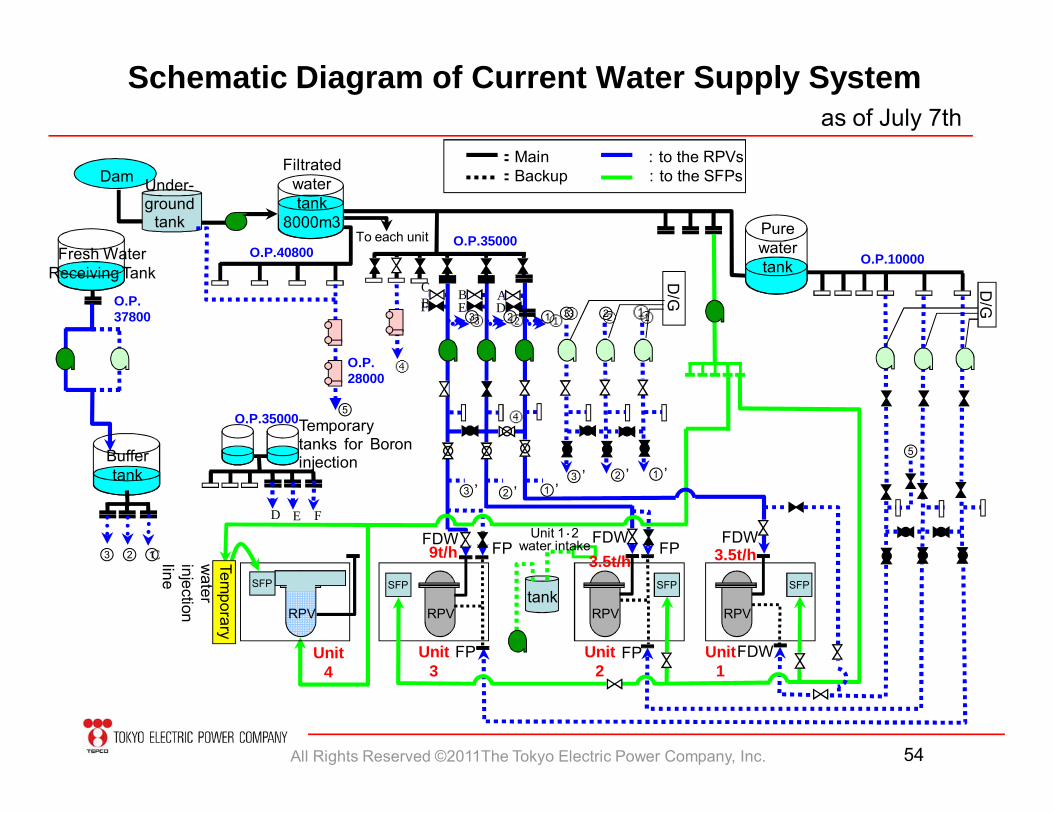
9t/hTemporary
water
injectionline
D/G D/G
3.5t/h
FDWFP FP
3.5t/h
⑤
O.P.35000
DEFB AC
B
FED
④
④
FP FPC
Schematic Diagram of Current Water Supply Systemas of July 7th
:Main :to the RPVs:Backup :to the SFPsDam
Filtrated water tank
8000m3
Under-ground
tank Pure water tank O.P.10000O.P.40800
O.P.35000
O.P.28000
O.P.37800
Fresh Water Receiving Tank
Buffer tank
Temporarytanks for Boroninjection
SFP SFP SFP SFP
Unit 3
Unit 2
Unit 1
FDW FDW FDWUnit 1・2 water intake
③ ② ①③ ② ①
③ ② ①
All Rights Reserved ©2011The Tokyo Electric Power Company, Inc. 55
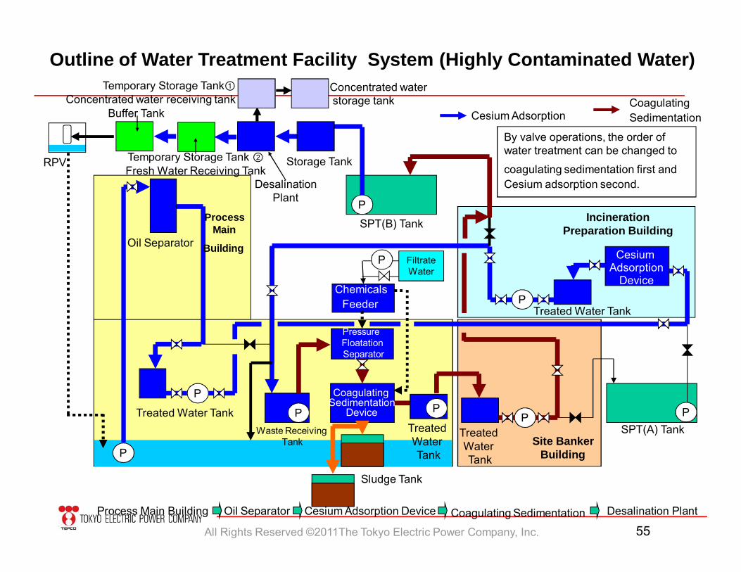
Outline of Water Treatment Facility System (Highly Contaminated Water)
P P
P
P
PP P
P
Oil Separator
SPT(B) Tank
SPT(A) Tank
Cesium Adsorption
Device
Treated Water Tank
Treated Water Tank
Coagulating Sedimentation
Device
Waste Receiving Tank
Treated Water Tank
Storage Tank
DesalinationPlant
Temporary Storage Tank ②Fresh Water Receiving Tank
Buffer Tank
Temporary Storage Tank①Concentrated water receiving tank
Concentrated waterstorage tank
Treated Water Tank
Sludge Tank
Process Main
Building
Site BankerBuilding
IncinerationPreparation Building
RPV
Cesium Adsorption
By valve operations, the order of water treatment can be changed to
coagulating sedimentation first andCesium adsorption second.
Pressure FloatationSeparator
Chemicals Feeder
Oil Separator Cesium Adsorption Device Coagulating Sedimentation Desalination PlantProcess Main Building
Coagulating Sedimentation
P Filtrate Water
All Rights Reserved ©2011The Tokyo Electric Power Company, Inc. 56
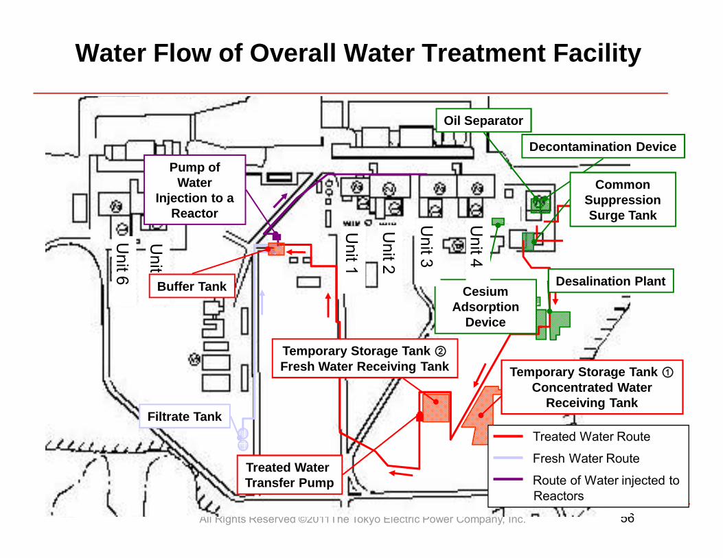
Water Flow of Overall Water Treatment Facility
Treated Water Route
Fresh Water Route
Route of Water injected toReactors
Oil Separator
Decontamination Device
Common Suppression Surge Tank
Cesium Adsorption
Device
Desalination Plant
Temporary Storage Tank ②Fresh Water Receiving Tank
Treated Water Transfer Pump
Filtrate Tank
Pump of Water
Injection to a Reactor
Temporary Storage Tank ①Concentrated Water
Receiving Tank
Unit 6
Unit 5
Unit 1
Unit 2
Unit 3
Unit 4
Buffer Tank
All Rights Reserved ©2011The Tokyo Electric Power Company, Inc. 57
Storing water with low radiation level
(
5) Atmosphere / Soil
Solidification of contaminated soil, etc
(
3) Accum
ulated Water
Start of installation work ofreactor building container
Transferring water with high radiation level
Installation of storage facilities /decontamination processing
Installation of full-fledged water processing facilities
(
4) Ground
water
II. M
itigation
Mitigation of contamination
in the ocean
Mitigation of contamination in the ocean
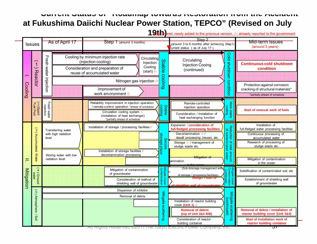
Current Status of Roadmap towards Restoration from the Accident at Fukushima Daiichi Nuclear Power Station, TEPCO” (Revised on July
19th)Mid-term issues Step 2
(around 3 to 6 months after achieving Step1)Step 1 (around 3 months)
(
2)Spent
Fuel Pool
Fresh water
injection
(
1) Reactor
As of April 17
Consideration / installation of heat exchanging function
Remote-controlledinjection operation
Circulation cooling system ☆(installation of heat exchanger)
*partially ahead of schedule
Start of removal work of fuels
More stablecooling
Reliability improvement in injection operation / remote-control operation *ahead of schedule
Stablecooling
I.C
ooling
Issues
Red colored: newly added to the previous version, ☆: already reported to the government
current status (as of July 17)
Fresh water Injection
Cold shutdow
n condition
Cooling by minimum injection rate(injection cooling)
Protection against corrosion cracking of structural materials*
Nitrogen gas injection ☆
Consideration and preparation of reuse of accumulated water
CirculatingInjection Cooing (continued)
Stable cooling
Removal of debris
Dispersion of inhibitor
Installation of reactor buildingcover (Unit 1) ☆
(Sub-drainage management with expansion
of storage / processing facilities)Design / start of
implementation of shielding wall of groundwater
Improvement of work environment ☆
Continuous processing of accumulated water
Establishment of shielding wall of groundwater
*partially ahead of schedule
Research of processing of sludge waste etc.
Mitigate ocean
Contam
ination(continued)
Mitigate scattering
(continued)
Mitigation of contaminationof groundwater
Storage ☆ / management ofsludge waste etc.
Reduction of total am
ountof contam
inated water
Consideration of reactor building container
Mitigate scattering
Circulating Injection Cooling (start) ☆
Continuous cold shutdown condition
(around 3 years)
Expansion / consideration of full-fledged processing facilitiesInstallation of storage / processing facilities☆
Decontamination ☆ /desalt processing (reuse), etcSecure
storage place
Consideration of method ofshielding wall of groundwater
Removal of debris (top of Unit 3&4 R/B)
Removal of debris / installation of reactor building cover (Unit 3&4)
Consideration of method of shielding wall of groundwater
Mitigate ocean
contamination
All Rights Reserved ©2011The Tokyo Electric Power Company, Inc. 58
Step 1 (around 3 months)
(
8) Life/work
environment
V. Environment im
provement
(
6) Measurem
ent, Reduction
and Announcem
ent
III. Monitoring/
Decontam
ination
Continuous environmental monitoring
IV. Counterm
easures against aftershocks, etc
(
7) Tsunami,
Reinforcem
ent, etc Reinforcement work of each Unit
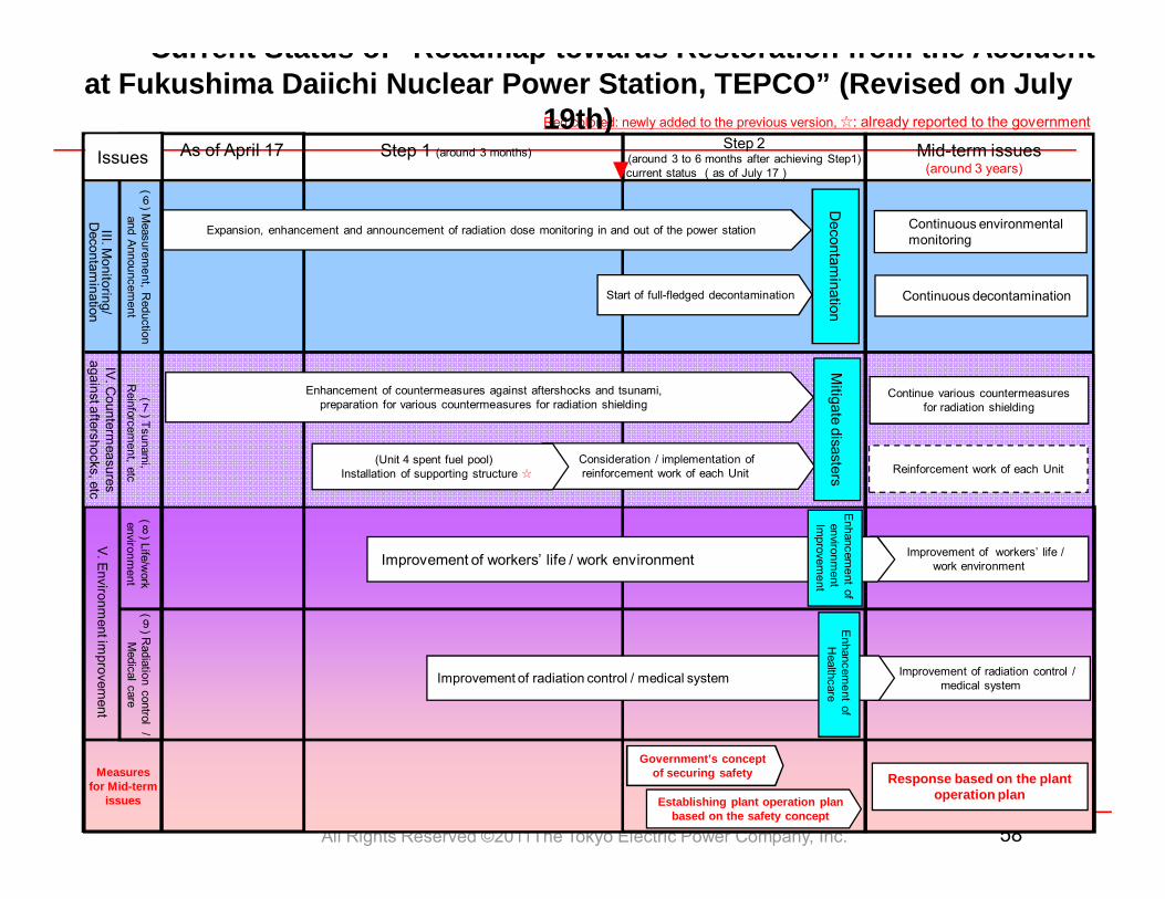
Mid-term issuesStep 2(around 3 to 6 months after achieving Step1)As of April 17current status (as of July 17)
Red colored: newly added to the previous version, ☆: already reported to the government
Issues
Enhancement of countermeasures against aftershocks and tsunami, preparation for various countermeasures for radiation shielding
Consideration / implementation ofreinforcement work of each Unit
(Unit 4 spent fuel pool) Installation of supporting structure ☆
Expansion, enhancement and announcement of radiation dose monitoring in and out of the power station
(
9) Radiation control /
Medical care
Mitigate disasters
Improvement of workers’ life / work environment
Improvement of radiation control / medical system
Measures for Mid-term
issues
Response based on the plant operation plan
Government’s concept of securing safety
Establishing plant operation plan based on the safety concept
(around 3 years)
Decontam
ination
Start of full-fledged decontamination Continuous decontamination
Continue various countermeasures for radiation shielding
Improvement of workers’ life / work environment
Enhancem
ent of environm
ent Im
provement
Improvement of radiation control / medical system
Enhancem
ent of H
ealthcare
Current Status of Roadmap towards Restoration from the Accident at Fukushima Daiichi Nuclear Power Station, TEPCO” (Revised on July
19th)
All Rights Reserved ©2011The Tokyo Electric Power Company, Inc. 59
P P
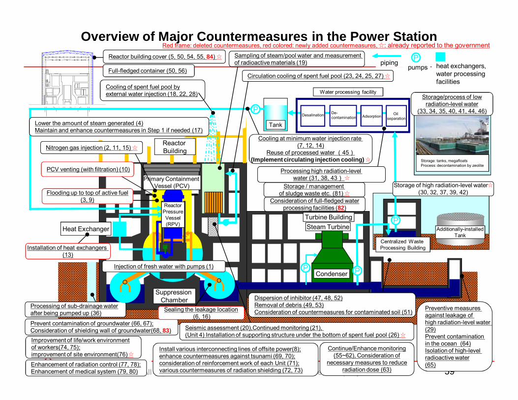
Overview of Major Countermeasures in the Power Station
Suppression Chamber
Primary Containment Vessel (PCV)
Turbine Building
Heat Exchanger
pipingP
pumps heat exchangers, water processing facilities
Steam Turbine
Condenser
Tank
Flooding up to top of active fuel(3, 9)
Reactor building cover (5, 50, 54, 55, 84) ☆
PCV venting (with filtration) (10)
Installation of heat exchangers (13)
Dispersion of inhibitor (47, 48, 52)Removal of debris (49, 53)Consideration of countermeasures for contaminated soil (51) Preventive measures
against leakage of high radiation-level water (29)Prevent contamination in the ocean (64)Isolation of high-level radioactive water(65)
Processing high radiation-level water (31, 38, 43) ☆
Additionally-installedTank
Storage/process of low radiation-level water
(33, 34, 35, 40, 41, 44, 46)
Storage: tanks, megafloatsProcess: decontamination by zeolite
Processing of sub-drainage water after being pumped up (36)
Reactor BuildingNitrogen gas injection (2, 11, 15) ☆
Cooling of spent fuel pool by external water injection (18, 22, 28)
P
Centralized Waste Processing Building
Storage of high radiation-level water☆(30, 32, 37, 39, 42)
Seismic assessment (20),Continued monitoring (21), (Unit 4) Installation of supporting structure under the bottom of spent fuel pool (26) ☆
Red frame: deleted countermeasures, red colored: newly added countermeasures, ☆: already reported to the government
Continue/Enhance monitoring (55~62), Consideration of
necessary measures to reduce radiation dose (63)
Full-fledged container (50, 56)
Lower the amount of steam generated (4)Maintain and enhance countermeasures in Step 1 if needed (17)
Prevent contamination of groundwater (66, 67); Consideration of shielding wall of groundwater(68, 83)
Install various interconnecting lines of offsite power(8); enhance countermeasures against tsunami (69, 70); consideration of reinforcement work of each Unit (71); various countermeasures of radiation shielding (72, 73)
Improvement of life/work environment of workers(74, 75); improvement of site environment(76) ☆Enhancement of radiation control (77, 78);Enhancement of medical system (79, 80)
Storage / management of sludge waste etc. (81) ☆
Sealing the leakage location(6, 16)
Water processing facility
Oil separationAdsorption
De-contaminationDesalination
P
Sampling of steam/pool water and measurement of radioactive materials (19)
Circulation cooling of spent fuel pool (23, 24, 25, 27) ☆
Cooling at minimum water injection rate (7, 12, 14)
Reuse of processed water (45)(Implement circulating injection cooling) ☆
Consideration of full-fledged water processing facilities (82)
Injection of fresh water with pumps (1)
Reactor Pressure Vessel (RPV)
All Rights Reserved ©2011The Tokyo Electric Power Company, Inc. 60
5. Summary
All Rights Reserved ©2011The Tokyo Electric Power Company, Inc. 61
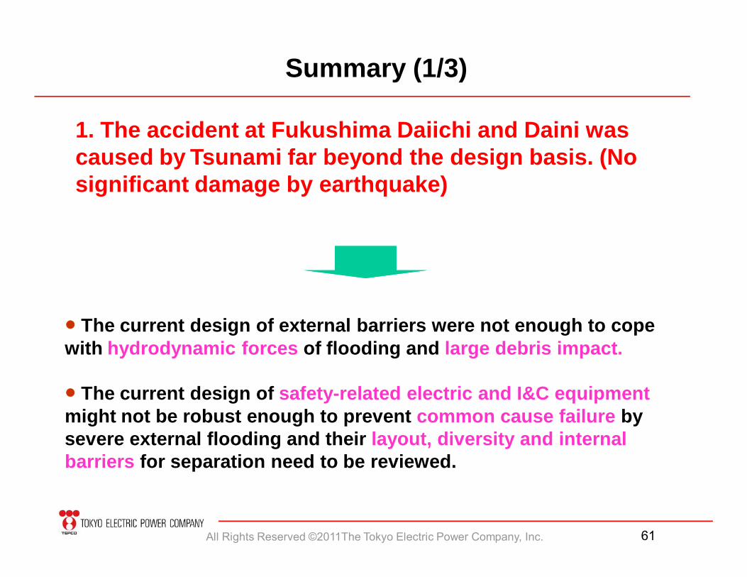
Summary (1/3)
1. The accident at Fukushima Daiichi and Daini was caused by Tsunami far beyond the design basis. (No significant damage by earthquake)
● The current design of external barriers were not enough to cope with hydrodynamic forces of flooding and large debris impact.
● The current design of safety-related electric and I&C equipmentmight not be robust enough to prevent common cause failure by severe external flooding and their layout, diversity and internal barriers for separation need to be reviewed.
All Rights Reserved ©2011The Tokyo Electric Power Company, Inc. 62
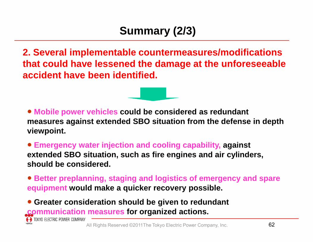
Summary (2/3)
● Mobile power vehicles could be considered as redundant measures against extended SBO situation from the defense in depth viewpoint.
● Emergency water injection and cooling capability, against extended SBO situation, such as fire engines and air cylinders, should be considered.
● Better preplanning, staging and logistics of emergency and spare equipment would make a quicker recovery possible.
● Greater consideration should be given to redundant communication measures for organized actions.
2. Several implementable countermeasures/modifications that could have lessened the damage at the unforeseeable accident have been identified.
All Rights Reserved ©2011The Tokyo Electric Power Company, Inc. 63
Summary (3/3)
3. Without newly built Emergency Response Center, the post-accident activities could not have been carried out.
● Measures taken after Niigata Chuetsu Oki Earthquake were effective:- Emergency response center in robust building (Seismic isolation,
Shielding, Communication, etc.)- Underground water tank (16 units/site×40 m3/site) and Fire Engines
(3/site)- Emergency Response Drills
All Rights Reserved ©2011The Tokyo Electric Power Company, Inc. 64
6. References
- Damage status of electric equipments- Restoration process
- Electric equipment - I&C- Measures to ensure safe shutdown @2F- Chronology
All Rights Reserved ©2011The Tokyo Electric Power Company, Inc. 65
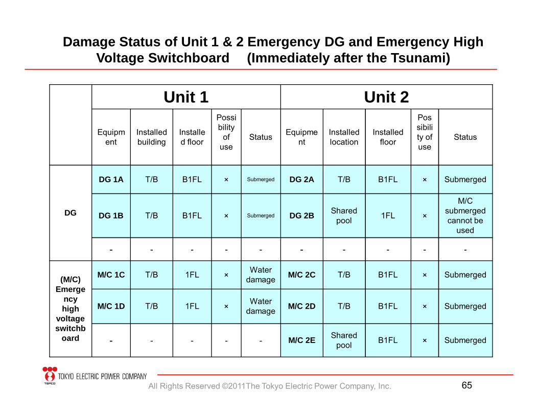
Unit 1 Unit 2
Equipment
Installed building
Installed floor
Possibility
of use
Status Equipment
Installed location
Installed floor
Possibility of use
Status
DG
DG 1A T/B B1FL × Submerged DG 2A T/B B1FL × Submerged
DG 1B T/B B1FL × Submerged DG 2B Shared pool 1FL ×
M/C submerged cannot be
used
- - - - - - - - - -
(M/C)Emerge
ncy high
voltage switchb
oard
M/C 1C T/B 1FL × Water damage M/C 2C T/B B1FL × Submerged
M/C 1D T/B 1FL × Water damage M/C 2D T/B B1FL × Submerged
- - - - - M/C 2E Shared pool B1FL × Submerged
Damage Status of Unit 1 & 2 Emergency DG and Emergency HighVoltage Switchboard (Immediately after the Tsunami)
All Rights Reserved ©2011The Tokyo Electric Power Company, Inc. 66
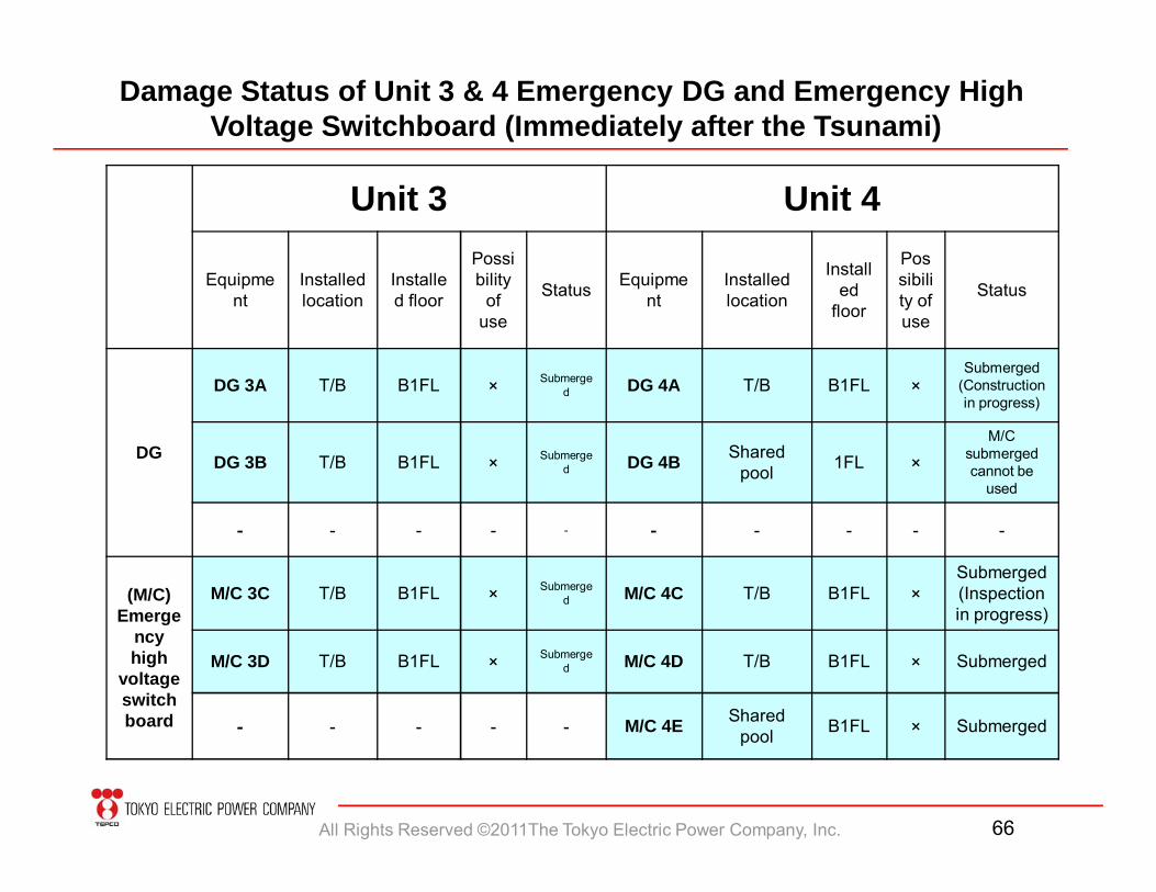
Unit 3 Unit 4
Equipment
Installed location
Installed floor
Possibility
of use
Status Equipment
Installed location
Installed
floor
Possibility of use
Status
DG
DG 3A T/B B1FL × Submerged DG 4A T/B B1FL ×
Submerged (Construction in progress)
DG 3B T/B B1FL × Submerged DG 4B Shared
pool 1FL ×M/C
submerged cannot be
used
- - - - - - - - - -
(M/C)Emerge
ncy high
voltage switchboard
M/C 3C T/B B1FL × Submerged M/C 4C T/B B1FL ×
Submerged (Inspection in progress)
M/C 3D T/B B1FL × Submerged M/C 4D T/B B1FL × Submerged
- - - - - M/C 4E Shared pool B1FL × Submerged
Damage Status of Unit 3 & 4 Emergency DG and Emergency High Voltage Switchboard (Immediately after the Tsunami)
All Rights Reserved ©2011The Tokyo Electric Power Company, Inc. 67
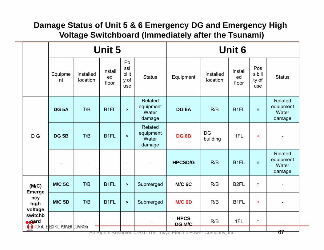
Unit 5 Unit 6
Equipment
Installed location
Installed
floor
Possibility of use
Status Equipment Installed location
Installed
floor
Possibility of use
Status
DG
DG 5A T/B B1FL ×
Related equipment
Water damage
DG 6A R/B B1FL ×
Related equipment
Water damage
DG 5B T/B B1FL ×
Related equipment
Water damage
DG 6B DG building 1FL ○ -
- - - - - HPCSD/G R/B B1FL ×
Related equipment
Water damage
(M/C)Emerge
ncy high
voltage switchb
oard
M/C 5C T/B B1FL × Submerged M/C 6C R/B B2FL ○ -
M/C 5D T/B B1FL × Submerged M/C 6D R/B B1FL ○ -
- - - - - HPCS DG M/C R/B 1FL ○ -
Damage Status of Unit 5 & 6 Emergency DG and Emergency High Voltage Switchboard (Immediately after the Tsunami)
All Rights Reserved ©2011The Tokyo Electric Power Company, Inc. 68
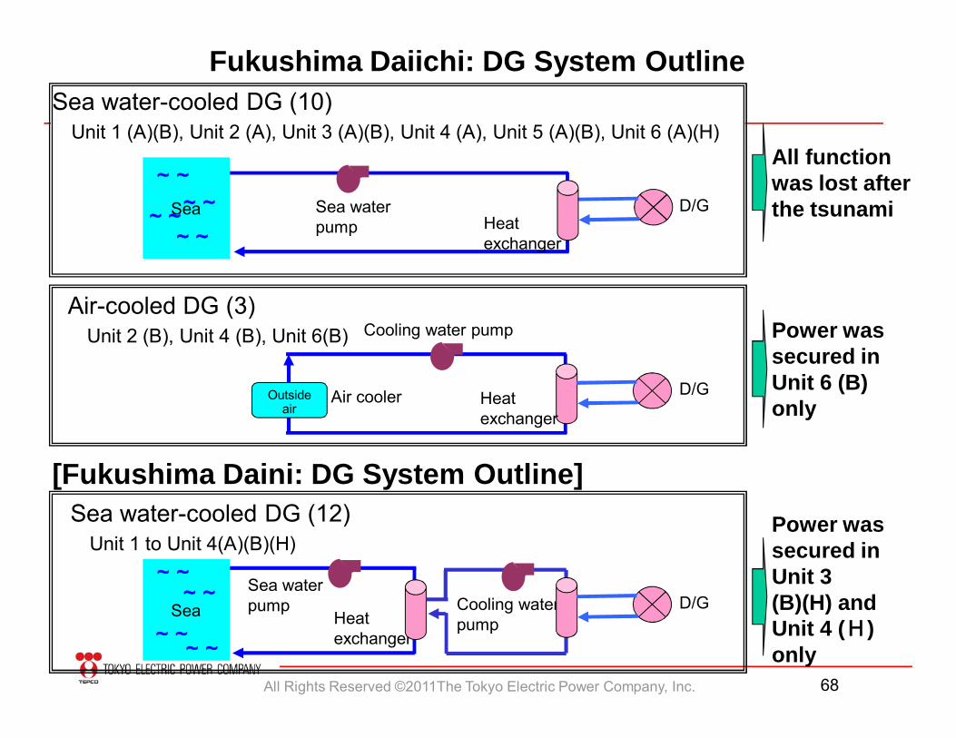
Fukushima Daiichi: DG System Outline
All function was lost after the tsunami
Power was secured in Unit 6 (B) only
[Fukushima Daini: DG System Outline]Power was secured in Unit 3 (B)(H) and Unit 4 (H) only
Sea water-cooled DG (10) Unit 1 (A)(B), Unit 2 (A), Unit 3 (A)(B), Unit 4 (A), Unit 5 (A)(B), Unit 6 (A)(H)
Air-cooled DG (3)Unit 2 (B), Unit 4 (B), Unit 6(B)
Sea water-cooled DG (12)Unit 1 to Unit 4(A)(B)(H)
Sea water pump
D/GHeat exchanger
Sea
~~~~
~~~~
Outside air
Air cooler D/G
Cooling water pump
Heat exchanger
Sea water pump
Heat exchanger
Cooling water pump
D/GSea
~~~~
~~~~
All Rights Reserved ©2011The Tokyo Electric Power Company, Inc. 69
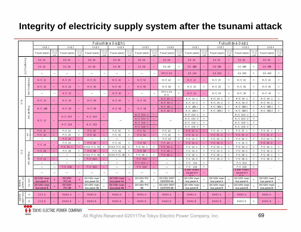
Integrity of electricity supply system after the tsunami attack
Power panelCan/cannot beused
Pow er panelCan/cannot beused
Pow er panelCan/cannot beused
Pow er panelCan/cannot beused
Pow er panelCan/cannot beused
Pow er panelCan/cannot beused
Pow er panelCan/cannot beused
Pow er panelCan/cannot beused
Pow er panelCan/cannot beused
Pow er panelCan/cannot beused
D G 1A × DG 2A × DG 3A × DG 4A × DG 5A × DG 6A × DG 1A × D G 2A × DG 3A × DG 4A ×
D G 1B × DG 2B × DG 3B × DG 4B × DG 5B × DG 6B ○ DG 1B × DG 2B × DG 3B ○ DG 4B ×
- - - - - - - - - - HPC S D G × DG 1H × DG 2H × DG 3H ○ DG 4H ○
M /C 1C × M /C 2C × M /C 3C × M /C 4C × M /C 5C × M /C 6C ○ M /C 1C × M /C 2C ○ M /C 3C ○ M /C 4C ○
M /C 1D × M /C 2D × M /C 3D × M /C 4D × M /C 5D × M /C 6D ○ M /C 1D ○ M /C 2D ○ M /C 3D ○ M /C 4D ○
- - M /C 2E × - - M /C 4E × - -HPC S D GM /C
○ M /C 1H × M /C 2H ○ M /C 3H ○ M /C 4H ○
M /C 6A-1 × M /C 1A-1 ○ M /C 2A-1 ○ M /C 3A-1 ○ M /C 4A-1 ○
M /C 6A-2 × M /C 1A-2 ○ M /C 2A-2 ○ M /C 3A-2 ○ M /C 4A-2 ○
M /C 6B-1 × M /C 1B-1 ○ M /C 2B-1 ○ M /C 3B-1 ○ M /C 4B-1 ○
M /C 6B-2 × M /C 1B-2 ○ M /C 2B-2 ○ M /C 3B-2 ○ M /C 4B-2 ○
M /C 5SA-1 × M /C 1SA-1 ○ M /C 3SA-1 ○
M /C 5SA-2 × M /C 1SA-2 ○ M /C 3SA-2 ○
M /C 5SB-1 × M /C 1SB-1 ○ M /C 3SB-1 ○
M /C 5SB-2 × M /C 1SB-2 ○ M /C 3SB-2 ○
P/C 1C × P/C 2C ○ P/C 3C × P/C 4C ○ P/C 5C × P/C 6C ○ P/C 1C-1 × P/C 2C-1 ○ P/C 3C -1 ○ P/C 4C -1 ○
P/C 1D × P/C 2D ○ P/C 3D × P/C 4D ○ P/C 5D × P/C 6D ○ P/C 1C-2 × P/C 2C-2 × P/C 3C -2 × P/C 4C -2 ×
- - P/C 2E × - - - - - - P/C 6E ○ P/C 1D-1 ○ P/C 2D-1 ○ P/C 3D-1 ○ P/C 4D-1 ○
P/C 2A ○ P/C 3A × P/C 4A ○ P/C 5A × P/C 6A-1 × P/C 1D-2 × P/C 2D-2 × P/C 3D-2 ○ P/C 4D-2 ×
P/C 2A-1 × HVAC P/C 3A △ HVAC P/C 4A △ P/C 5A-1 ○ P/C 6A-2 × P/C 1A-1 ○ P/C 2A-1 ○ P/C 3A-1 ○ P/C 4A-1 ○
P/C 1B × P/C 2B ○ P/C 3B × P/C 4B ○ P/C 5B × P/C 6B-1 × P/C 1A-2 ○ P/C 2A-2 ○ P/C 3A-2 ○ P/C 4A-2 ○
- - - - HVAC P/C 3B △ HVAV P/C 4B △ P/C 5B-1 ○ P/C 6B-2 × P/C 1B-1 ○ P/C 2B-1 ○ P/C 3B-1 ○ P/C 4B-1 ○
P/C 1S × - - P/C 3SA × - - P/C 5SA × - - P/C 1B-2 ○ P/C 2B-2 ○ P/C 3B-2 ○ P/C 4B-2 ○
- - - - - - - - P/C 5SA-1 × - - P/C 1SA ○ P/C 3SA ○
- - P/C 2SB × P/C 3SB × - - P/C 5SB × - - P/C 1SB ○ P/C 3SB ○
- - - - - - - - - - - -W ater intakeequipm entP/C
×W ater intakeequipm entP/C
×
DC125V mainbus panel A × DC125V
P/C 2A × DC125V mainbus panel 3A ○
DC125V mainbus panel 4A × DC125V P/C
5A ○DC125V DISTCENTER 6A ○
DC125V mainbus panel A ○
DC125V mainbus panel A ○
DC125V mainbus panel A ○
DC125V mainbus panel A ○
DC125V mainbus panel B × DC125V
P/C 2B × DC125V mainbus panel 3B ○
DC125V mainbus panel 4B × DC125V P/C
5B ○DC125V DISTCENTER 6B ○
DC125V mainbus panel B ○
DC125V mainbus panel B ○
DC125V mainbus panel B ○
DC125V mainbus panel B ○
A C CS A × RHRS A × RHRS A × RHRS A × RHRS A × RHRS A × RHRS A × RHRS A × RHRS A × RHRS A ×
B CC S B × RHRS B × RHRS B × RHRS B × RHRS B × RHRS B × RHRS B × RHRS B × RHRS B ○ RHRS B ×
- -
- -
Fukushim a D aiichiUnit 1 Unit 2
Fukushim a D ainiUnit 1 Unit 2 Unit 3 Unit 4Unit 3 Unit 5Unit 4 Unit 6
×M /C 2A
Emergency use
M /C 1A ×
M /C 1S ×
M /C 1B × ××× M /C 3BM /C 2B
M /C 3A
×M /C 5BM /C 4B
M /C 5AM /C 4A ×××
M /C 2SB
M /C 2SA
×
×
×
× M /C 3SA
M /C 3SB
Emergency
useRegular u
se
P /C 1A ×
-
Sea water
system
DC power
supply
125V DC
P/C
Emergency DG
M/C
-
Regular use
All Rights Reserved ©2011The Tokyo Electric Power Company, Inc. 70
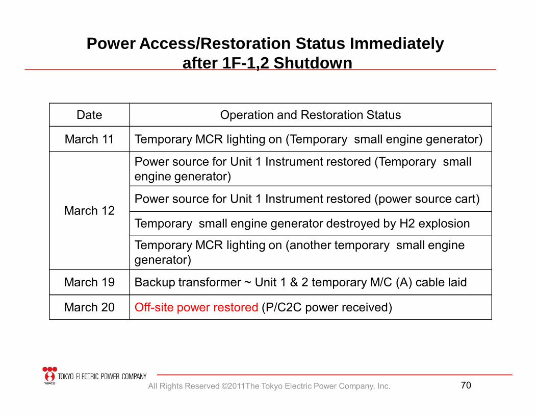
Power Access/Restoration Status Immediately after 1F-1,2 Shutdown
Date Operation and Restoration Status
March 11 Temporary MCR lighting on (Temporary small engine generator)
March 12
Power source for Unit 1 Instrument restored (Temporary small engine generator)
Power source for Unit 1 Instrument restored (power source cart)
Temporary small engine generator destroyed by H2 explosion
Temporary MCR lighting on (another temporary small engine generator)
March 19 Backup transformer ~ Unit 1 & 2 temporary M/C (A) cable laid
March 20 Off-site power restored (P/C2C power received)
All Rights Reserved ©2011The Tokyo Electric Power Company, Inc. 71
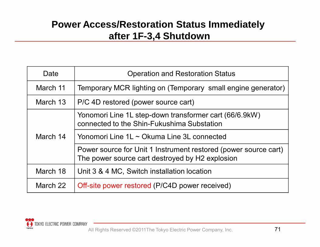
Power Access/Restoration Status Immediately after 1F-3,4 Shutdown
Date Operation and Restoration Status
March 11 Temporary MCR lighting on (Temporary small engine generator)
March 13 P/C 4D restored (power source cart)
March 14
Yonomori Line 1L step-down transformer cart (66/6.9kW) connected to the Shin-Fukushima Substation
Yonomori Line 1L ~ Okuma Line 3L connected
Power source for Unit 1 Instrument restored (power source cart) The power source cart destroyed by H2 explosion
March 18 Unit 3 & 4 MC, Switch installation location
March 22 Off-site power restored (P/C4D power received)
All Rights Reserved ©2011The Tokyo Electric Power Company, Inc. 72
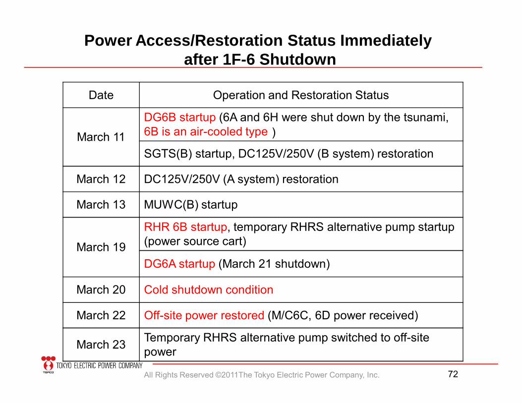
Power Access/Restoration Status Immediately after 1F-6 Shutdown
Date Operation and Restoration Status
March 11
DG6B startup (6A and 6H were shut down by the tsunami, 6B is an air-cooled type)
SGTS(B) startup, DC125V/250V (B system) restoration
March 12 DC125V/250V (A system) restoration
March 13 MUWC(B) startup
March 19
RHR 6B startup, temporary RHRS alternative pump startup (power source cart)
DG6A startup (March 21 shutdown)
March 20 Cold shutdown condition
March 22 Off-site power restored (M/C6C, 6D power received)
March 23 Temporary RHRS alternative pump switched to off-site power
All Rights Reserved ©2011The Tokyo Electric Power Company, Inc. 73
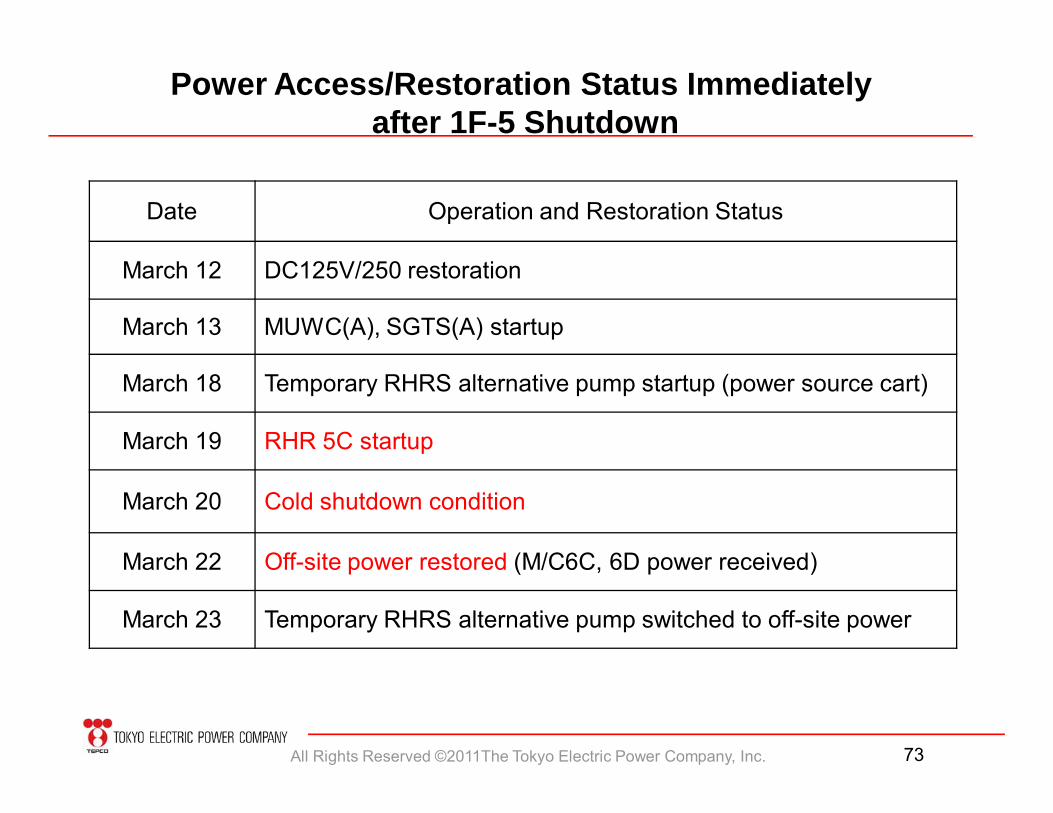
Date Operation and Restoration Status
March 12 DC125V/250 restoration
March 13 MUWC(A), SGTS(A) startup
March 18 Temporary RHRS alternative pump startup (power source cart)
March 19 RHR 5C startup
March 20 Cold shutdown condition
March 22 Off-site power restored (M/C6C, 6D power received)
March 23 Temporary RHRS alternative pump switched to off-site power
Power Access/Restoration Status Immediately after 1F-5 Shutdown
All Rights Reserved ©2011The Tokyo Electric Power Company, Inc. 74
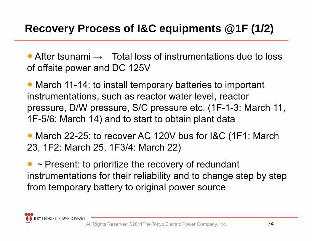
Recovery Process of I&C equipments @1F (1/2)
● After tsunami → Total loss of instrumentations due to loss of offsite power and DC 125V
● March 11-14: to install temporary batteries to important instrumentations, such as reactor water level, reactor pressure, D/W pressure, S/C pressure etc. (1F-1-3: March 11, 1F-5/6: March 14) and to start to obtain plant data
● March 22-25: to recover AC 120V bus for I&C (1F1: March 23, 1F2: March 25, 1F3/4: March 22)
● ~Present: to prioritize the recovery of redundant instrumentations for their reliability and to change step by step from temporary battery to original power source
All Rights Reserved ©2011The Tokyo Electric Power Company, Inc. 75
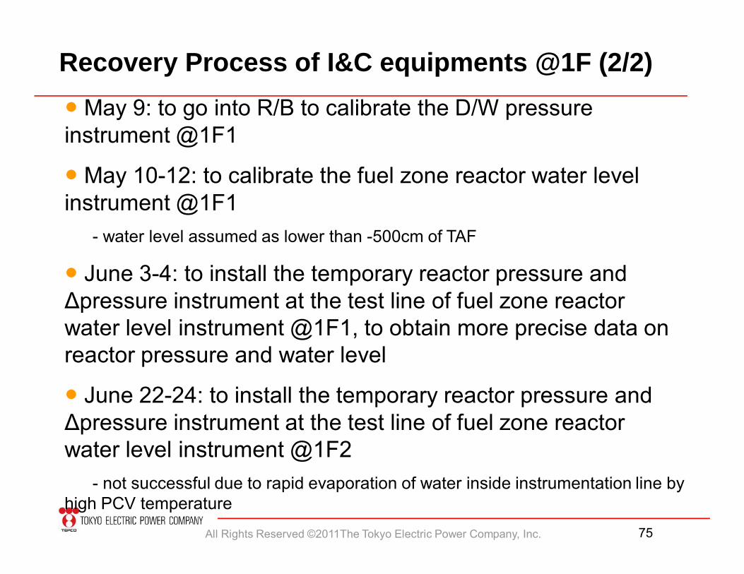
Recovery Process of I&C equipments @1F (2/2)● May 9: to go into R/B to calibrate the D/W pressure instrument @1F1
● May 10-12: to calibrate the fuel zone reactor water level instrument @1F1
- water level assumed as lower than -500cm of TAF
● June 3-4: to install the temporary reactor pressure and Δpressure instrument at the test line of fuel zone reactor water level instrument @1F1, to obtain more precise data on reactor pressure and water level
● June 22-24: to install the temporary reactor pressure and Δpressure instrument at the test line of fuel zone reactor water level instrument @1F2
- not successful due to rapid evaporation of water inside instrumentation line by high PCV temperature
All Rights Reserved ©2011The Tokyo Electric Power Company, Inc. 76
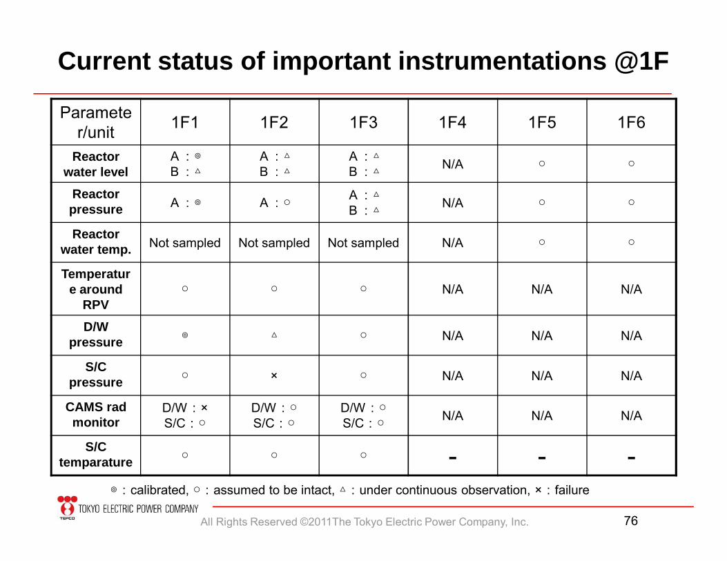
Current status of important instrumentations @1F
Parameter/unit 1F1 1F2 1F3 1F4 1F5 1F6
Reactor water level
A:◎B:△
A:△B:△
A:△B:△ N/A ○ ○
Reactor pressure A:◎ A:○ A:△
B:△ N/A ○ ○
Reactor water temp. Not sampled Not sampled Not sampled N/A ○ ○
Temperature around
RPV○ ○ ○ N/A N/A N/A
D/W pressure ◎ △ ○ N/A N/A N/A
S/C pressure ○ × ○ N/A N/A N/A
CAMS rad monitor
D/W:×S/C:○
D/W:○S/C:○
D/W:○S/C:○ N/A N/A N/A
S/C temparature ○ ○ ○ - - -
◎:calibrated, ○:assumed to be intact, △:under continuous observation, ×:failure
All Rights Reserved ©2011The Tokyo Electric Power Company, Inc. 77
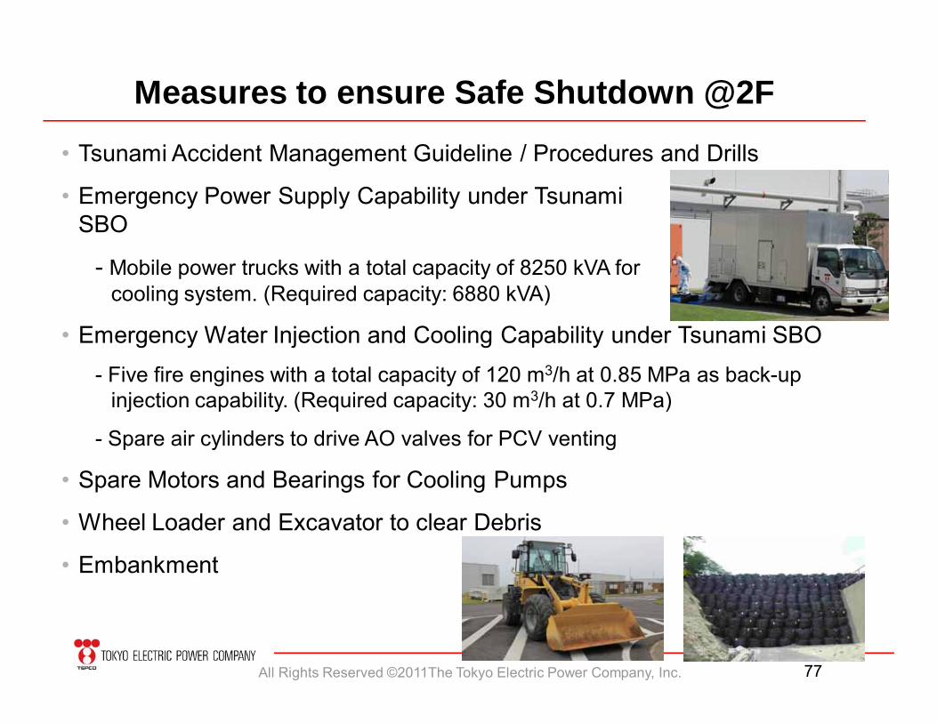
Measures to ensure Safe Shutdown @2F
• Tsunami Accident Management Guideline / Procedures and Drills
• Emergency Power Supply Capability under TsunamiSBO
- Mobile power trucks with a total capacity of 8250 kVA for cooling system. (Required capacity: 6880 kVA)
• Emergency Water Injection and Cooling Capability under Tsunami SBO- Five fire engines with a total capacity of 120 m3/h at 0.85 MPa as back-up
injection capability. (Required capacity: 30 m3/h at 0.7 MPa)
- Spare air cylinders to drive AO valves for PCV venting
• Spare Motors and Bearings for Cooling Pumps
• Wheel Loader and Excavator to clear Debris
• Embankment
All Rights Reserved ©2011The Tokyo Electric Power Company, Inc. 78
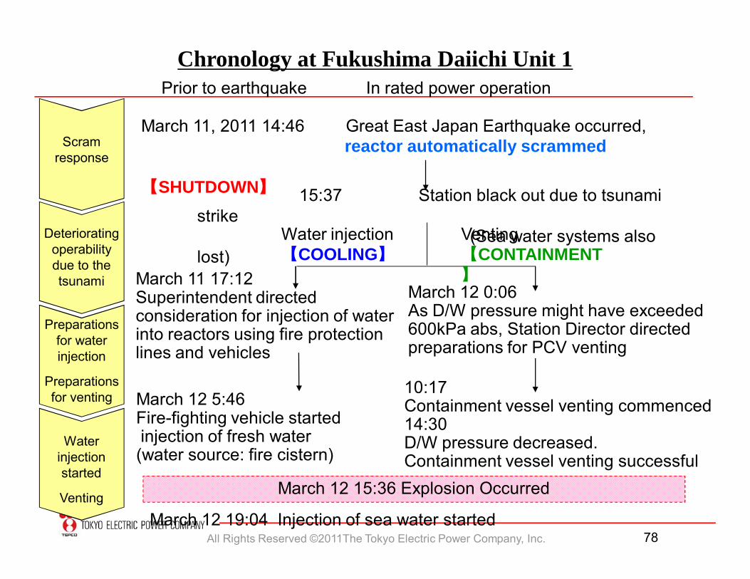
Chronology at Fukushima Daiichi Unit 1Prior to earthquake In rated power operation
March 11, 2011 14:46 Great East Japan Earthquake occurred,reactor automatically scrammed
【SHUTDOWN】 15:37 Station black out due to tsunami strike
(Sea water systems also lost)
March 11 17:12Superintendent directedconsideration for injection of waterinto reactors using fire protectionlines and vehicles
March 12 0:06As D/W pressure might have exceeded600kPa abs, Station Director directedpreparations for PCV venting
10:17Containment vessel venting commenced14:30D/W pressure decreased. Containment vessel venting successful
March 12 19:04 Injection of sea water started
Water injection【COOLING】
Venting【CONTAINMENT】
March 12 15:36 Explosion Occurred
Scram response
Deteriorating operability due to the tsunami
Preparations for water injection
Preparations for venting
Water injectionstarted
Venting
March 12 5:46Fire-fighting vehicle startedinjection of fresh water (water source: fire cistern)
All Rights Reserved ©2011The Tokyo Electric Power Company, Inc. 79
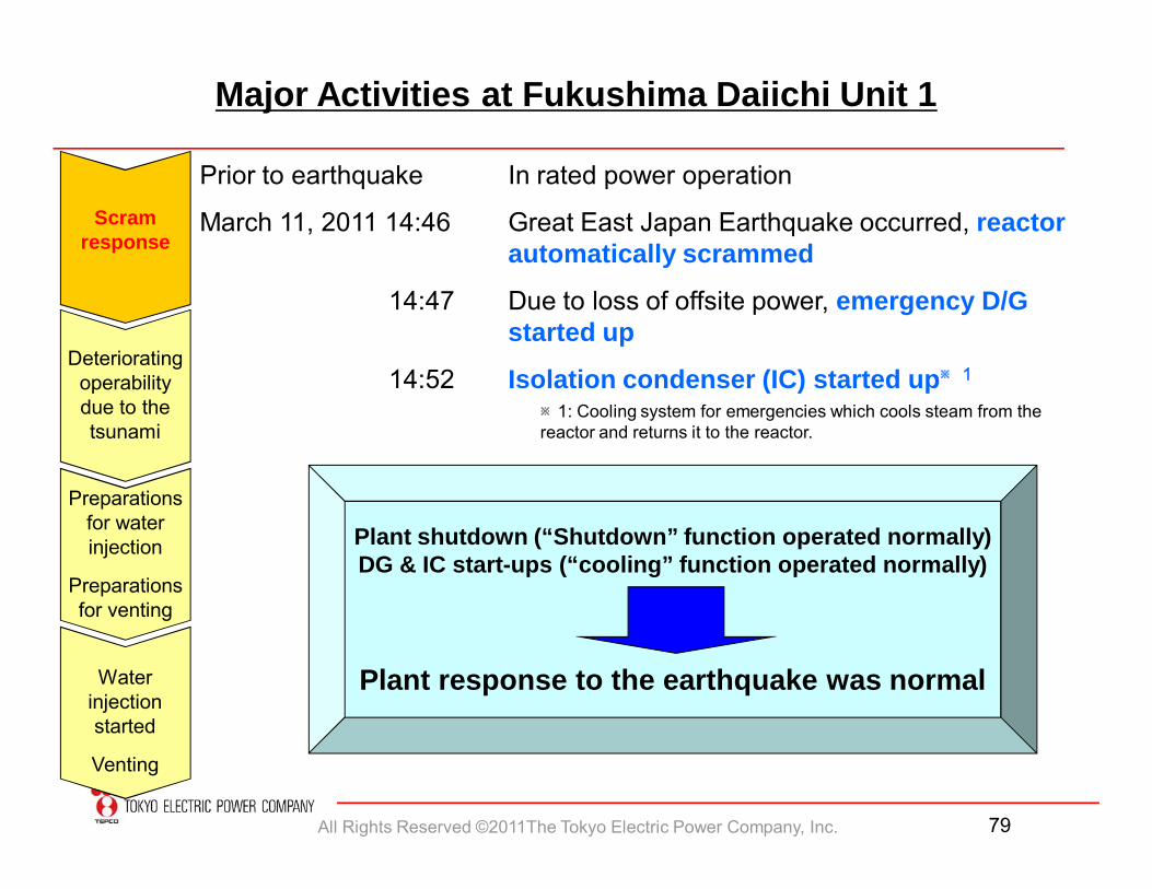
Prior to earthquake In rated power operation
March 11, 2011 14:46 Great East Japan Earthquake occurred, reactor automatically scrammed
14:47 Due to loss of offsite power, emergency D/G started up
14:52 Isolation condenser (IC) started up※1
Major Activities at Fukushima Daiichi Unit 1
Plant shutdown (“Shutdown” function operated normally)DG & IC start-ups (“cooling” function operated normally)
Plant response to the earthquake was normal
Scram response
Deteriorating operability due to the tsunami
Preparations for water injection
Preparations for venting
Water injectionstarted
Venting
※1: Cooling system for emergencies which cools steam from the reactor and returns it to the reactor.
All Rights Reserved ©2011The Tokyo Electric Power Company, Inc. 80
Major Activities at Fukushima Daiichi Unit 1
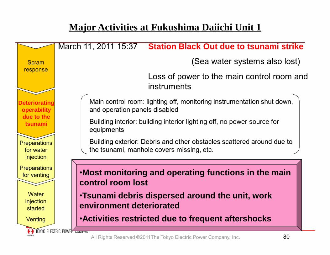
March 11, 2011 15:37 Station Black Out due to tsunami strike
(Sea water systems also lost)
Loss of power to the main control room and instruments
•Most monitoring and operating functions in the main control room lost •Tsunami debris dispersed around the unit, work environment deteriorated •Activities restricted due to frequent aftershocks
Main control room: lighting off, monitoring instrumentation shut down, and operation panels disabled
Building interior: building interior lighting off, no power source for equipments
Building exterior: Debris and other obstacles scattered around due to the tsunami, manhole covers missing, etc.
Scram response
Deteriorating operability due to the tsunami
Preparations for water injection
Preparations for venting
Water injectionstarted
Venting
All Rights Reserved ©2011The Tokyo Electric Power Company, Inc. 81
Scram response
Deteriorating operability due to the tsunami
Preparations for water injection
Preparations for venting
Water injectionstarted
Venting
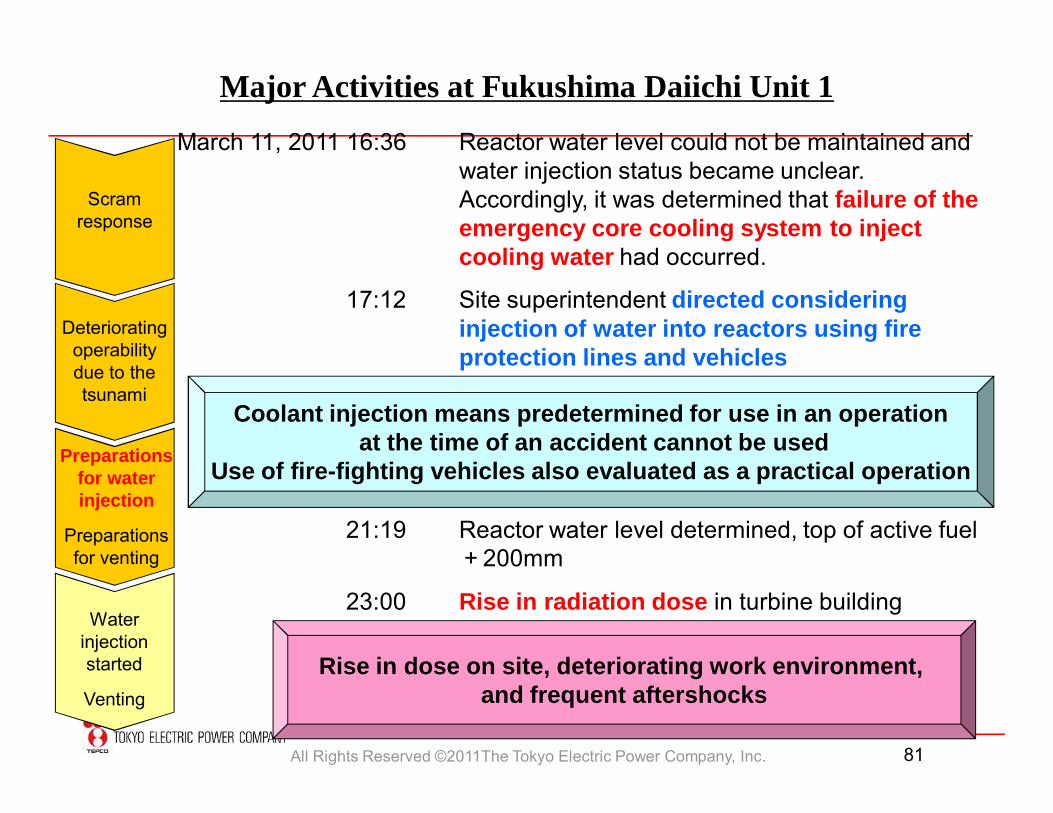
Major Activities at Fukushima Daiichi Unit 1
March 11, 2011 16:36 Reactor water level could not be maintained and water injection status became unclear. Accordingly, it was determined that failure of the emergency core cooling system to inject cooling water had occurred.
17:12 Site superintendent directed considering injection of water into reactors using fire protection lines and vehicles
21:19 Reactor water level determined, top of active fuel +200mm
23:00 Rise in radiation dose in turbine building
Coolant injection means predetermined for use in an operationat the time of an accident cannot be used
Use of fire-fighting vehicles also evaluated as a practical operation
Rise in dose on site, deteriorating work environment, and frequent aftershocks
All Rights Reserved ©2011The Tokyo Electric Power Company, Inc. 82
Scram response
Deteriorating operability due to the tsunami
Water injectionstarted
Venting
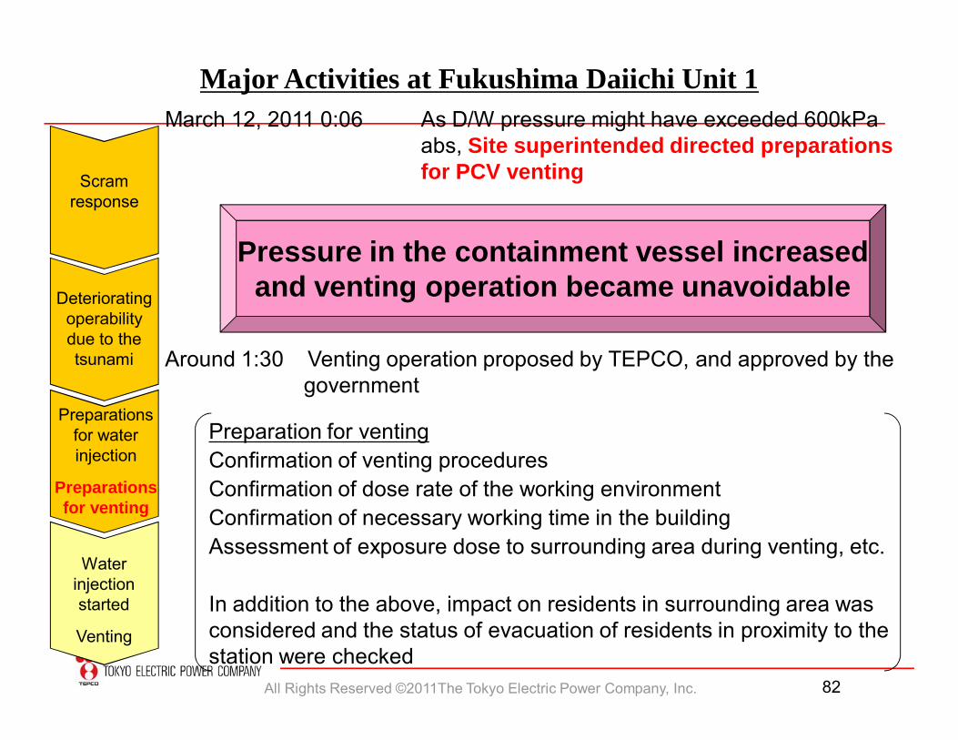
Major Activities at Fukushima Daiichi Unit 1March 12, 2011 0:06 As D/W pressure might have exceeded 600kPa
abs, Site superintended directed preparations for PCV venting
Pressure in the containment vessel increasedand venting operation became unavoidable
Around 1:30 Venting operation proposed by TEPCO, and approved by thegovernment
Preparation for ventingConfirmation of venting proceduresConfirmation of dose rate of the working environmentConfirmation of necessary working time in the buildingAssessment of exposure dose to surrounding area during venting, etc.
In addition to the above, impact on residents in surrounding area was considered and the status of evacuation of residents in proximity to the station were checked
Preparations for water injection
Preparations for venting
All Rights Reserved ©2011The Tokyo Electric Power Company, Inc. 83
Scram response
Deteriorating operability due to the tsunami
Water injectionstarted
Venting
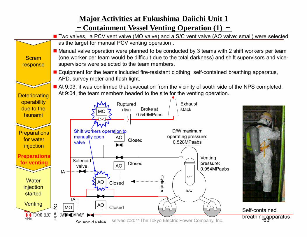
Major Activities at Fukushima Daiichi Unit 1~Containment Vessel Venting Operation (1) ~
Self-contained breathing apparatus
Two valves, a PCV vent valve (MO valve) and a S/C vent valve (AO valve: small) were selected as the target for manual PCV venting operation .
Manual valve operation were planned to be conducted by 3 teams with 2 shift workers per team (one worker per team would be difficult due to the total darkness) and shift supervisors and vice-supervisors were selected to the team members.
Equipment for the teams included fire-resistant clothing, self-contained breathing apparatus, APD, survey meter and flash light.
At 9:03, it was confirmed that evacuation from the vicinity of south side of the NPS completed.At 9:04, the team members headed to the site for the venting operation.
72AO
ボンベ
210MO ラプチャーディスク
排気筒
1AO
ボンベ
閉
閉
83AO
閉
閉90AO
0.549MPabsで破壊
RPV
D/W
RPVRPV
D/W
IA
IA
D/W最高使用圧力0.528MPabs
ベント実施圧力0.954MPabs
電磁弁
電磁弁
213AO
Shift workers operation to manually open valve
MO
AO
AO
AO
AO
MO
Exhaust stack
Closed
Closed
Closed
Closed
Solenoid valve
Solenoid valve
Cylinder
Cylinder
D/W maximum operating pressure:
0.528MPaabs
Ruptured disc Broke at
0.549MPabs
Venting pressure:0.954MPaabs
Preparations for water injection
Preparations for venting
All Rights Reserved ©2011The Tokyo Electric Power Company, Inc. 84
Water injectionstarted
Venting
Major Activities at Fukushima Daiichi Unit 1~Containment Vessel Venting Operation (2) ~
72AO
ボンベ
210MO ラプチャーディスク
排気筒
1AO
ボンベ
閉
閉
83AO
閉
閉90AO
0.549MPabsで破壊
RPV
D/W
RPVRPV
D/W
IA
IA
D/W最高使用圧力0.528MPabs
ベント実施圧力0.954MPabs
電磁弁
電磁弁
213AO
(25%開)
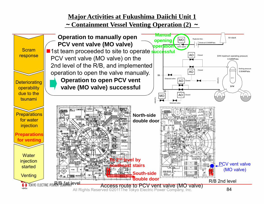
1st team proceeded to site to operate PCV vent valve (MO valve) on the 2nd level of the R/B, and implemented operation to open the valve manually.
R/B 2nd levelR/B 1st level
South-sidedouble door
To 2nd level by southeast stairs PCV vent valve
(MO valve)
North-sidedouble door
Operation to open PCV vent valve (MO valve) successful
Access route to PCV vent valve (MO valve)
Manual opening
operation successful
MO
MO
AO
AO
AO
AO
Ruptured disc
Broke at 0.549MPabs
Air stack
Closed
Closed
ClosedSolenoid valve
Solenoid valve
Cylinder
Cylinder
D/W maximum operating pressure
Venting pressure
Closed
(25% open)
Operation to manually open PCV vent valve (MO valve)
Scram response
Deteriorating operability due to the tsunami
Preparations for water injection
Preparations for venting
All Rights Reserved ©2011The Tokyo Electric Power Company, Inc. 85
Water injectionstarted
Venting
Major Activities at Fukushima Daiichi Unit 1~Containment Vessel Venting Operation (3) ~
72AO
ボンベ
210MO ラプチャーディスク
排気筒
1AO
ボンベ
閉
閉
83AO
閉
閉90AO
0.549MPabsで破壊
RPV
D/W
RPVRPV
D/W
IA
IA
D/W最高使用圧力0.528MPabs
ベント実施圧力0.954MPabs
電磁弁
電磁弁
213AO
(25%開)
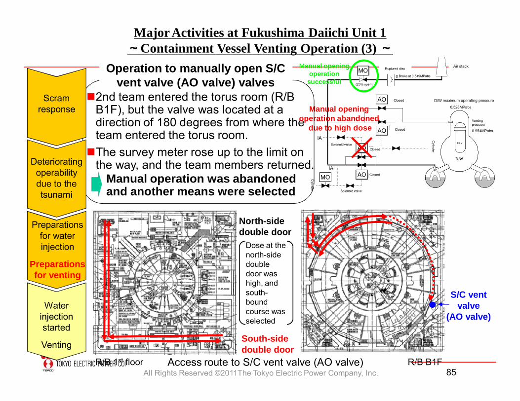
2nd team entered the torus room (R/B B1F), but the valve was located at a direction of 180 degrees from where the team entered the torus room.The survey meter rose up to the limit on
the way, and the team members returned.
R/B 1st floor R/B B1F
S/C vent valve
(AO valve)
Dose at the north-side double door was high, and south-bound course was selected
Manual operation was abandoned and another means were selected
Access route to S/C vent valve (AO valve)
Manual openingoperation
successful
AO
AO
Manual opening operation abandoned
due to high dose
AO
AOMO
MO Ruptured disc
Broke at 0.549MPabs
Air stack
Closed
Closed
ClosedSolenoid valve
Solenoid valve
Cylinder
Cylinder
D/W maximum operating pressure
Venting pressure
Closed
(25% open)
Operation to manually open S/C vent valve (AO valve) valves
South-sidedouble door
North-sidedouble door
Deteriorating operability due to the tsunami
Scram response
Preparations for water injection
Preparations for venting
All Rights Reserved ©2011The Tokyo Electric Power Company, Inc. 86
Scram response
Deteriorating operability due to the tsunami
Preparations for water injection
Preparations for venting
Water injectionstarted
Venting
Major Activities at Fukushima Daiichi Unit 1
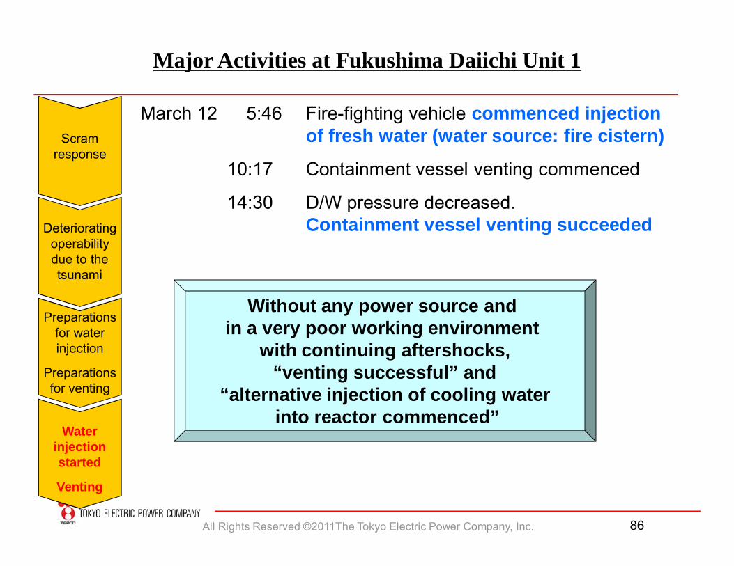
March 12 5:46 Fire-fighting vehicle commenced injection of fresh water (water source: fire cistern)
10:17 Containment vessel venting commenced
14:30 D/W pressure decreased. Containment vessel venting succeeded
Without any power source and in a very poor working environment
with continuing aftershocks,“venting successful” and
“alternative injection of cooling waterinto reactor commenced”
All Rights Reserved ©2011The Tokyo Electric Power Company, Inc. 87
Scram response
Deteriorating operability due to the tsunami
Preparations for water injection
Preparations for venting
Water injectionstarted
Venting
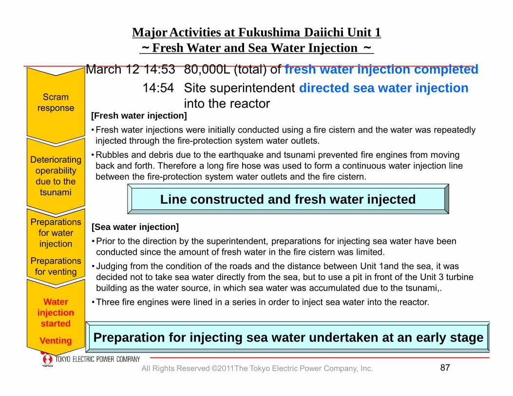
Major Activities at Fukushima Daiichi Unit 1~Fresh Water and Sea Water Injection ~
[Sea water injection]• Prior to the direction by the superintendent, preparations for injecting sea water have been conducted since the amount of fresh water in the fire cistern was limited.
• Judging from the condition of the roads and the distance between Unit 1and the sea, it was decided not to take sea water directly from the sea, but to use a pit in front of the Unit 3 turbine building as the water source, in which sea water was accumulated due to the tsunami,.
• Three fire engines were lined in a series in order to inject sea water into the reactor.
March 12 14:53 80,000L (total) of fresh water injection completed14:54 Site superintendent directed sea water injection
into the reactor [Fresh water injection]• Fresh water injections were initially conducted using a fire cistern and the water was repeatedly injected through the fire-protection system water outlets.
• Rubbles and debris due to the earthquake and tsunami prevented fire engines from moving back and forth. Therefore a long fire hose was used to form a continuous water injection line between the fire-protection system water outlets and the fire cistern.
Line constructed and fresh water injected
Preparation for injecting sea water undertaken at an early stage
All Rights Reserved ©2011The Tokyo Electric Power Company, Inc. 88
Deteriorating operability due to the tsunami
Preparations for water injection
Preparations for venting
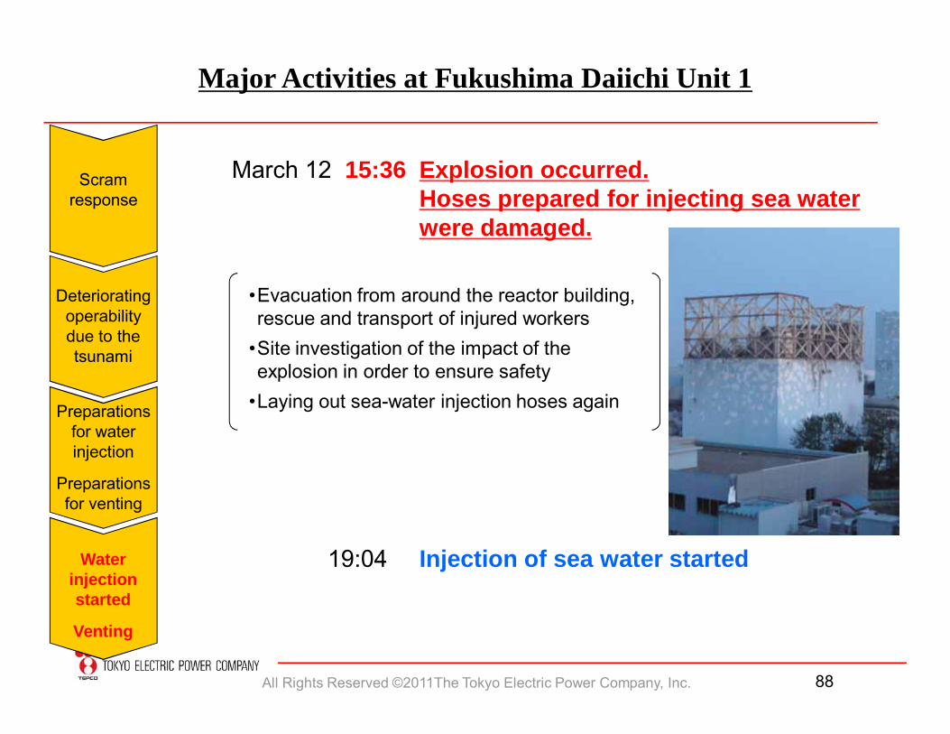
Major Activities at Fukushima Daiichi Unit 1
March 12 15:36 Explosion occurred. Hoses prepared for injecting sea water were damaged.
19:04 Injection of sea water started
•Evacuation from around the reactor building, rescue and transport of injured workers
•Site investigation of the impact of the explosion in order to ensure safety
•Laying out sea-water injection hoses again
Scram response
Water injectionstarted
Venting
All Rights Reserved ©2011The Tokyo Electric Power Company, Inc. 89
Water injection using R
CIC
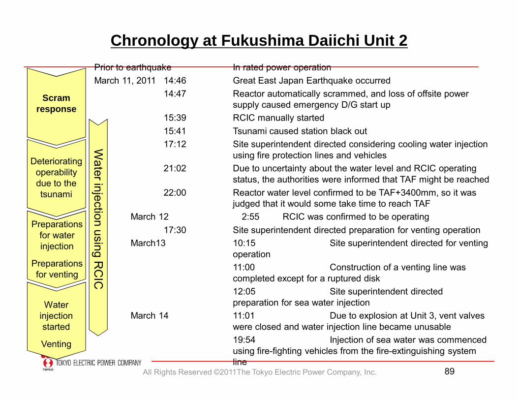
Chronology at Fukushima Daiichi Unit 2
Scram response
Deteriorating operability due to the tsunami
Preparations for water injection
Preparations for venting
Water injectionstarted
Venting
Prior to earthquake In rated power operationMarch 11, 2011 14:46 Great East Japan Earthquake occurred
14:47 Reactor automatically scrammed, and loss of offsite power supply caused emergency D/G start up
15:39 RCIC manually started15:41 Tsunami caused station black out17:12 Site superintendent directed considering cooling water injection
using fire protection lines and vehicles21:02 Due to uncertainty about the water level and RCIC operating
status, the authorities were informed that TAF might be reached22:00 Reactor water level confirmed to be TAF+3400mm, so it was
judged that it would some take time to reach TAFMarch 12 2:55 RCIC was confirmed to be operating
17:30 Site superintendent directed preparation for venting operationMarch13 10:15 Site superintendent directed for venting
operation11:00 Construction of a venting line was completed except for a ruptured disk12:05 Site superintendent directed preparation for sea water injection
March 14 11:01 Due to explosion at Unit 3, vent valves were closed and water injection line became unusable19:54 Injection of sea water was commenced using fire-fighting vehicles from the fire-extinguishing system line
All Rights Reserved ©2011The Tokyo Electric Power Company, Inc. 90
Water injection using R
CIC
/HP
CI
Scram response
Deteriorating operability due to the tsunami
Preparations for water injection
Preparations for venting
Water injectionstarted
Venting
Chronology at Fukushima Daiichi Unit 3
Prior to earthquake In rated power operationMarch 11, 2011 14:46 Great East Japan Earthquake occurred
14:47 Reactor automatically scrammedApprox. 14:48 Loss of offsite power supply caused emergency D/G to start up
15:38 Tsunami caused station black out16:03 RCIC manually started
March 12 11:36 RCIC tripped12:35 HPCI automatically started (low reactor water level)
17:30 Site superintendent directed preparation for venting operationMarch13 2:42 HPCI tripped
5:15 Site superintendent directed venting line to be constructed except for a ruptured disk8:41 Construction of a venting line was
completed except for the ruptured diskApprox. 9:20 Venting operation confirmed decrease in the D/W pressure
9:25 Injection of fresh water commenced using fire-fighting vehicles from fire-extinguishing line (~12:00)13:12 Injection of sea water commenced using fire-fighting vehicles from fire-extinguishing line
March 14 11:01 Explosion in the reactor building (fire-fighting vehicles and hoses damaged)
Approx. 16:30 Fire-fighting vehicles and hoses were replaced and injection of sea water recommenced