Embed Size (px)
Citation preview
Upgrade and Maintenance Manual - English
FUJITSU Server PRIMERGY RX2530 M1Upgrade and Maintenance Manual
August 2015
Comments… Suggestions… Corrections…The User Documentation Department would like toknow your opinion of this manual. Your feedback helpsus optimize our documentation to suit your individual needs.
Feel free to send us your comments by e-mail to [email protected].
Certified documentation according to DIN EN ISO 9001:2008To ensure a consistently high quality standard anduser-friendliness, this documentation was created tomeet the regulations of a quality management system which complies with the requirements of the standardDIN EN ISO 9001:2008.
cognitas. Gesellschaft für Technik-Dokumentation mbHwww.cognitas.de
Copyright and TrademarksCopyright © 2015 Fujitsu Technology Solutions GmbH.
All rights reserved.Delivery subject to availability; right of technical modifications reserved.
All hardware and software names used are trademarks of their respective manufacturers.
– The contents of this manual may be revised without prior notice.
– Fujitsu assumes no liability for damages to third party copyrights or other rights arising from the use of any information in this manual.
– No part of this manual may be reproduced in any form without the prior written permission of Fujitsu.
Microsoft, Windows, Windows Server, and Hyper V are trademarks or registered trademarks of Microsoft Corporation in the USA and other countries.
Intel and Xeon are trademarks or registered trademarks of Intel Corporation or its subsidiaries in the USA and other countries.
RX2530 M1 Upgrade and Maintenance Manual
Before reading this manual
For your safety
This manual contains important information for safely and correctly using this product.
Carefully read the manual before using this product. Pay particular attention to the accompanying manual "Safety Notes and Regulations" and ensure these safety notes are understood before using the product. Keep this manual and the manual "Safety Notes and Regulations" in a safe place for easy reference while using this product.
Radio interference
This product is a "Class A" ITE (Information Technology Equipment). In a domestic environment this product may cause radio interference, in which case the user may be required to take appropriate measures. VCCI-A
Aluminum electrolytic capacitors
The aluminum electrolytic capacitors used in the product's printed circuit board assemblies and in the mouse and keyboard are limited-life components. Use of these components beyond their operating life may result in electrolyte leakage or depletion, potentially causing emission of foul odor or smoke.
As a guideline, in a normal office environment (25°C) operating life is not expected to be reached within the maintenance support period (5 years). However, operating life may be reached more quickly if, for example, the product is used in a hot environment. The customer shall bear the cost of replacing replaceable components which have exceeded their operating life. Note that these are only guidelines, and do not constitute a guarantee of trouble-free operation during the maintenance support period.
High safety use
This product has been designed and manufactured to be used in commercial and/or industrial areas as a server.
When used as visual display workplace, it must not be placed in the direct field of view to avoid incommoding reflections (applies only to TX server systems).
The device has not been designed or manufactured for uses which demand an extremely high level of safety and carry a direct and serious risk of life or body if such safety cannot be assured.

Upgrade and Maintenance Manual RX2530 M1
These uses include control of nuclear reactions in nuclear power plants, automatic airplane flight control, air traffic control, traffic control in mass transport systems, medical devices for life support, and missile guidance control in weapons systems (hereafter, "high safety use"). Customers should not use this product for high safety use unless measures are in place for ensuring the level of safety demanded of such use. Please consult the sales staff of Fujitsu if intending to use this product for high safety use.
Measures against momentary voltage drop
This product may be affected by a momentary voltage drop in the power supply caused by lightning. To prevent a momentary voltage drop, use of an AC uninterruptible power supply is recommended.
(This notice follows the guidelines of Voltage Dip Immunity of Personal Computer issued by JEITA, the Japan Electronics and Information Technology Industries Association.)
Technology controlled by the Foreign Exchange and Foreign Trade Control Law of Japan
Documents produced by Fujitsu may contain technology controlled by the Foreign Exchange and Foreign Trade Control Law of Japan. Documents which contain such technology should not be exported from Japan or transferred to non-residents of Japan without first obtaining authorization in accordance with the above law.
Harmonic Current Standards
This product conforms to harmonic current standard JIS C 61000-3-2.
Only for the Japanese market: About SATA hard disk drives
The SATA version of this server supports hard disk drives with SATA / BC-SATA storage interfaces. Please note that the usage and operation conditions differ depending on the type of hard disk drive used.
Please refer to the following internet address for further information on the usage and operation conditions of each available type of hard disk drive:
http://jp.fujitsu.com/platform/server/primergy/harddisk/
RX2530 M1 Upgrade and Maintenance Manual
Only for the Japanese market:
Shielded LAN cables should be used in this product.
Only for the Japanese market:
I Although described in this manual, some sections do not apply to the Japanese market. These options and routines include:
– CSS (Customer Self Service)
– USB Flash Module (UFM)
Upgrade and Maintenance Manual RX2530 M1
Version history
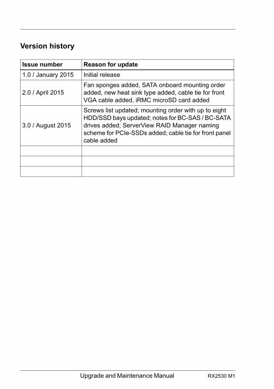
Issue number Reason for update
1.0 / January 2015 Initial release
2.0 / April 2015Fan sponges added, SATA onboard mounting order added, new heat sink type added, cable tie for front VGA cable added, iRMC microSD card added
3.0 / August 2015
Screws list updated; mounting order with up to eight HDD/SSD bays updated; notes for BC-SAS / BC-SATA drives added; ServerView RAID Manager naming scheme for PCIe-SSDs added; cable tie for front panel cable added
RX2530 M1 Upgrade and Maintenance Manual
Contents
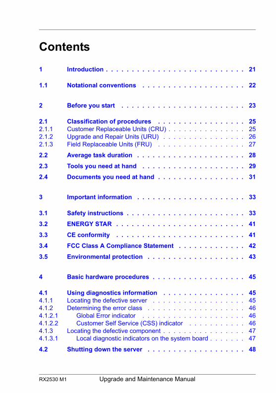
1 Introduction . . . . . . . . . . . . . . . . . . . . . . . . . . . 21
1.1 Notational conventions . . . . . . . . . . . . . . . . . . . . 22
2 Before you start . . . . . . . . . . . . . . . . . . . . . . . . 23
2.1 Classification of procedures . . . . . . . . . . . . . . . . . 252.1.1 Customer Replaceable Units (CRU) . . . . . . . . . . . . . . . 252.1.2 Upgrade and Repair Units (URU) . . . . . . . . . . . . . . . . 262.1.3 Field Replaceable Units (FRU) . . . . . . . . . . . . . . . . . 27
2.2 Average task duration . . . . . . . . . . . . . . . . . . . . . 28
2.3 Tools you need at hand . . . . . . . . . . . . . . . . . . . . 29
2.4 Documents you need at hand . . . . . . . . . . . . . . . . . 31
3 Important information . . . . . . . . . . . . . . . . . . . . . 33
3.1 Safety instructions . . . . . . . . . . . . . . . . . . . . . . . 33
3.2 ENERGY STAR . . . . . . . . . . . . . . . . . . . . . . . . . 41
3.3 CE conformity . . . . . . . . . . . . . . . . . . . . . . . . . 41
3.4 FCC Class A Compliance Statement . . . . . . . . . . . . . 42
3.5 Environmental protection . . . . . . . . . . . . . . . . . . . 43
4 Basic hardware procedures . . . . . . . . . . . . . . . . . . 45
4.1 Using diagnostics information . . . . . . . . . . . . . . . . 454.1.1 Locating the defective server . . . . . . . . . . . . . . . . . . 454.1.2 Determining the error class . . . . . . . . . . . . . . . . . . . 464.1.2.1 Global Error indicator . . . . . . . . . . . . . . . . . . . . 464.1.2.2 Customer Self Service (CSS) indicator . . . . . . . . . . . 464.1.3 Locating the defective component . . . . . . . . . . . . . . . . 474.1.3.1 Local diagnostic indicators on the system board . . . . . . . 47
4.2 Shutting down the server . . . . . . . . . . . . . . . . . . . 48
Upgrade and Maintenance Manual RX2530 M1
Contents
4.3 Disconnecting the server from the mains . . . . . . . . . . . 49
4.4 Getting access to the component . . . . . . . . . . . . . . . 494.4.1 Extending the server out of the rack . . . . . . . . . . . . . . . 504.4.2 Removing the server from the rack . . . . . . . . . . . . . . . . 514.4.3 Removing the top covers . . . . . . . . . . . . . . . . . . . . . 53
4.5 Reassembling . . . . . . . . . . . . . . . . . . . . . . . . . . 544.5.1 Installing the top covers . . . . . . . . . . . . . . . . . . . . . . 544.5.2 Mounting the server in the rack . . . . . . . . . . . . . . . . . . 574.5.3 Sliding the server into the rack . . . . . . . . . . . . . . . . . . 59
4.6 Connecting the server to the mains . . . . . . . . . . . . . . 60
4.7 Switching on the server . . . . . . . . . . . . . . . . . . . . . 61
4.8 Handling riser modules . . . . . . . . . . . . . . . . . . . . . 624.8.1 Removing a riser module . . . . . . . . . . . . . . . . . . . . . 624.8.2 Installing a riser module . . . . . . . . . . . . . . . . . . . . . . 63
4.9 Handling fan sponges . . . . . . . . . . . . . . . . . . . . . . 654.9.1 Removing the fan sponges . . . . . . . . . . . . . . . . . . . . 664.9.2 Installing the fan sponges . . . . . . . . . . . . . . . . . . . . . 67
4.10 Handling CPU air guides . . . . . . . . . . . . . . . . . . . . 684.10.1 Removing the CPU air guides . . . . . . . . . . . . . . . . . . 684.10.2 Installing the CPU air guides . . . . . . . . . . . . . . . . . . . 69
5 Basic software procedures . . . . . . . . . . . . . . . . . . . 71
5.1 Starting the maintenance task . . . . . . . . . . . . . . . . . 715.1.1 Suspending BitLocker functionality . . . . . . . . . . . . . . . . 715.1.2 Disabling SVOM boot watchdog functionality . . . . . . . . . . . 725.1.2.1 Viewing boot watchdog settings . . . . . . . . . . . . . . . . 725.1.2.2 Configuring boot watchdog settings . . . . . . . . . . . . . . 735.1.3 Removing backup and optical disk media . . . . . . . . . . . . 745.1.4 Verifying and configuring the backup software solution . . . . . . 755.1.5 Note on server maintenance in a Multipath I/O environment . . . 755.1.6 Switching on the ID indicator . . . . . . . . . . . . . . . . . . . 78
5.2 Completing the maintenance task . . . . . . . . . . . . . . . 795.2.1 Updating or recovering the system board BIOS and iRMC . . . . 795.2.1.1 Updating or recovering the system board BIOS . . . . . . . . 795.2.1.2 Updating or recovering the iRMC . . . . . . . . . . . . . . . 795.2.2 Verifying system information backup / restore . . . . . . . . . . 815.2.3 Updating RAID controller firmware . . . . . . . . . . . . . . . . 82
RX2530 M1 Upgrade and Maintenance Manual
Contents
5.2.4 Enabling Option ROM scan . . . . . . . . . . . . . . . . . . . 835.2.5 Verifying and configuring the backup software solution . . . . . 845.2.6 Resetting the boot retry counter . . . . . . . . . . . . . . . . . 845.2.6.1 Viewing the boot retry counter . . . . . . . . . . . . . . . . 855.2.6.2 Resetting the boot retry counter . . . . . . . . . . . . . . . 855.2.7 Resetting the error status after replacing memory modules or
processors . . . . . . . . . . . . . . . . . . . . . . . . . . . . 865.2.7.1 Memory modules . . . . . . . . . . . . . . . . . . . . . . . 865.2.7.2 Processors . . . . . . . . . . . . . . . . . . . . . . . . . . 885.2.8 Enabling SVOM boot watchdog functionality . . . . . . . . . . 895.2.9 Enabling replaced components in the system BIOS . . . . . . . 905.2.10 Verifying the memory mode . . . . . . . . . . . . . . . . . . . 915.2.11 Verifying the system time settings . . . . . . . . . . . . . . . . 915.2.12 Viewing and clearing the System Event Log (SEL) . . . . . . . 925.2.12.1 Viewing the SEL . . . . . . . . . . . . . . . . . . . . . . . 925.2.12.2 Clearing the SEL . . . . . . . . . . . . . . . . . . . . . . . 935.2.13 Updating the NIC configuration file in a Linux environment . . . 935.2.14 Resuming BitLocker functionality . . . . . . . . . . . . . . . . 955.2.15 Performing a RAID array rebuild . . . . . . . . . . . . . . . . . 965.2.16 Looking up changed MAC / WWN addresses . . . . . . . . . . 965.2.16.1 Looking up MAC addresses . . . . . . . . . . . . . . . . . 965.2.16.2 Looking up WWN addresses . . . . . . . . . . . . . . . . . 975.2.17 Using the Chassis ID Prom Tool . . . . . . . . . . . . . . . . . 985.2.18 Configuring LAN teaming . . . . . . . . . . . . . . . . . . . . 995.2.18.1 After replacing / upgrading LAN controllers . . . . . . . . . 995.2.18.2 After replacing the system board . . . . . . . . . . . . . . . 995.2.19 Switching off the ID indicator . . . . . . . . . . . . . . . . . . 1005.2.20 Performing a fan test after replacing a defective fan . . . . . . 100
6 Power supply . . . . . . . . . . . . . . . . . . . . . . . . . . 103
6.1 Basic information . . . . . . . . . . . . . . . . . . . . . . . 1046.1.1 Power supply unit configurations . . . . . . . . . . . . . . . . 1056.1.2 Assembly rules . . . . . . . . . . . . . . . . . . . . . . . . . 105
6.2 Installing a power supply unit . . . . . . . . . . . . . . . . . 1066.2.1 Preliminary steps . . . . . . . . . . . . . . . . . . . . . . . . 1066.2.2 Removing the dummy cover . . . . . . . . . . . . . . . . . . . 1066.2.3 Installing a power supply unit . . . . . . . . . . . . . . . . . . 1076.2.4 Concluding steps . . . . . . . . . . . . . . . . . . . . . . . . 108
Upgrade and Maintenance Manual RX2530 M1
Contents
6.3 Removing a power supply unit . . . . . . . . . . . . . . . . 1096.3.1 Preliminary steps . . . . . . . . . . . . . . . . . . . . . . . . 1116.3.2 Removing a power supply unit . . . . . . . . . . . . . . . . . 1116.3.3 Installing the dummy cover . . . . . . . . . . . . . . . . . . . 112
6.4 Replacing a power supply unit . . . . . . . . . . . . . . . . 1136.4.1 Preliminary steps . . . . . . . . . . . . . . . . . . . . . . . . 1146.4.2 Removing the defective power supply unit . . . . . . . . . . . 1146.4.3 Installing the new power supply unit . . . . . . . . . . . . . . 1146.4.4 Concluding steps . . . . . . . . . . . . . . . . . . . . . . . . 114
7 Hard disk drives / solid state drives . . . . . . . . . . . . . 115
7.1 Basic information . . . . . . . . . . . . . . . . . . . . . . . 116
7.2 2.5-inch HDD/SSD configurations . . . . . . . . . . . . . . 1177.2.1 Equipping the 2.5-inch HDD/SSD bays . . . . . . . . . . . . . 1177.2.2 Configuration with up to four HDD/SSD modules . . . . . . . . 1177.2.3 Configuration with up to eight HDD/SSD modules . . . . . . . 1187.2.4 Configuration with up to 10 HDD/SSD modules . . . . . . . . 1207.2.5 Installing 2.5-inch HDD/SSD modules . . . . . . . . . . . . . 1237.2.5.1 Preliminary steps . . . . . . . . . . . . . . . . . . . . . . 1237.2.5.2 Removing a 2.5-inch HDD/SSD dummy module . . . . . . 1237.2.5.3 Installing a 2.5-inch HDD/SSD module . . . . . . . . . . . 1247.2.5.4 Concluding steps . . . . . . . . . . . . . . . . . . . . . . 1257.2.6 Removing 2.5-inch HDD/SSD modules . . . . . . . . . . . . . 1267.2.6.1 Preliminary steps . . . . . . . . . . . . . . . . . . . . . . 1267.2.6.2 Removing a 2.5-inch HDD/SSD module . . . . . . . . . . 1277.2.6.3 Installing a 2.5-inch HDD/SSD dummy module . . . . . . . 1277.2.6.4 Concluding steps . . . . . . . . . . . . . . . . . . . . . . 1277.2.7 Replacing a 2.5-inch HDD/SSD module . . . . . . . . . . . . 1287.2.7.1 Preliminary steps . . . . . . . . . . . . . . . . . . . . . . 1287.2.7.2 Removing the defective 2.5-inch HDD/SSD module . . . . 1287.2.7.3 Installing the new 2.5-inch HDD/SSD module . . . . . . . . 1297.2.7.4 Concluding steps . . . . . . . . . . . . . . . . . . . . . . 1297.2.8 Replacing the 4 x 2.5-inch HDD backplane . . . . . . . . . . . 1297.2.8.1 Preliminary steps . . . . . . . . . . . . . . . . . . . . . . 1297.2.8.2 Removing the defective 4 x 2.5-inch HDD backplane . . . . 1307.2.8.3 Installing the new 4 x 2.5-inch HDD backplane . . . . . . . 1337.2.8.4 Concluding steps . . . . . . . . . . . . . . . . . . . . . . 135
RX2530 M1 Upgrade and Maintenance Manual
Contents
7.2.9 Replacing the 10 x 2.5-inch HDD backplane . . . . . . . . . . 1367.2.9.1 Preliminary steps . . . . . . . . . . . . . . . . . . . . . . . 1367.2.9.2 Removing the SAS expander board . . . . . . . . . . . . . 1377.2.9.3 Removing the defective 10 x 2.5-inch HDD backplane . . . 1397.2.9.4 Installing the new 10 x 2.5-inch HDD backplane . . . . . . . 1397.2.9.5 Installing the SAS expander board . . . . . . . . . . . . . . 1407.2.9.6 Concluding steps . . . . . . . . . . . . . . . . . . . . . . . 1417.2.10 Replacing the SAS expander board . . . . . . . . . . . . . . . 1427.2.10.1 Preliminary steps . . . . . . . . . . . . . . . . . . . . . . . 1427.2.10.2 Removing the defective SAS expander board . . . . . . . . 1427.2.10.3 Installing the new SAS expander board . . . . . . . . . . . 1427.2.10.4 Concluding steps . . . . . . . . . . . . . . . . . . . . . . . 1427.2.11 Upgrading configuration from up to four to up to eight 2.5-inch
HDDs/SSDs . . . . . . . . . . . . . . . . . . . . . . . . . . . 1437.2.11.1 Preliminary steps . . . . . . . . . . . . . . . . . . . . . . . 1437.2.11.2 Installing the second HDD backplane . . . . . . . . . . . . 1437.2.11.3 Installing additional HDD/SSD modules . . . . . . . . . . . 1447.2.11.4 Concluding steps . . . . . . . . . . . . . . . . . . . . . . . 144
7.3 3.5-inch HDD configurations . . . . . . . . . . . . . . . . . 1457.3.1 Equipping the 3.5-inch HDD bays . . . . . . . . . . . . . . . . 1457.3.2 Installing 3.5-inch HDD modules . . . . . . . . . . . . . . . . 1467.3.2.1 Preliminary steps . . . . . . . . . . . . . . . . . . . . . . . 1467.3.2.2 Removing a 3.5-inch HDD dummy module . . . . . . . . . 1467.3.2.3 Installing a 3.5-inch HDD module . . . . . . . . . . . . . . 1477.3.2.4 Concluding steps . . . . . . . . . . . . . . . . . . . . . . . 1477.3.3 Removing 3.5-inch HDD modules . . . . . . . . . . . . . . . . 1487.3.3.1 Preliminary steps . . . . . . . . . . . . . . . . . . . . . . . 1487.3.3.2 Removing a 3.5-inch HDD module . . . . . . . . . . . . . . 1497.3.3.3 Installing a 3.5-inch dummy module . . . . . . . . . . . . . 1497.3.3.4 Concluding steps . . . . . . . . . . . . . . . . . . . . . . . 1497.3.4 Replacing a 3.5-inch HDD module . . . . . . . . . . . . . . . 1507.3.4.1 Preliminary steps . . . . . . . . . . . . . . . . . . . . . . . 1507.3.4.2 Removing the defective 3.5-inch HDD module . . . . . . . 1517.3.4.3 Installing the new 3.5-inch HDD module . . . . . . . . . . . 1517.3.4.4 Concluding steps . . . . . . . . . . . . . . . . . . . . . . . 1517.3.5 Replacing the 3.5-inch HDD backplane . . . . . . . . . . . . . 1517.3.5.1 Preliminary steps . . . . . . . . . . . . . . . . . . . . . . . 1517.3.5.2 Removing the defective 3.5-inch HDD backplane . . . . . . 1527.3.5.3 Installing the new 3.5-inch HDD backplane . . . . . . . . . 1537.3.5.4 Concluding steps . . . . . . . . . . . . . . . . . . . . . . . 154
Upgrade and Maintenance Manual RX2530 M1
Contents
8 Fans . . . . . . . . . . . . . . . . . . . . . . . . . . . . . . 155
8.1 Basic information . . . . . . . . . . . . . . . . . . . . . . . 1558.1.1 Numbering of the fan modules . . . . . . . . . . . . . . . . . 156
8.2 Replacing a defective fan module . . . . . . . . . . . . . . 1588.2.1 Preliminary steps . . . . . . . . . . . . . . . . . . . . . . . . 1588.2.2 Removing the defective fan module . . . . . . . . . . . . . . 1588.2.3 Installing the new fan module . . . . . . . . . . . . . . . . . . 1598.2.4 Concluding steps . . . . . . . . . . . . . . . . . . . . . . . . 160
9 Expansion cards and backup units . . . . . . . . . . . . . 161
9.1 Basic information . . . . . . . . . . . . . . . . . . . . . . . 1629.1.1 Equipping the PCIe slots . . . . . . . . . . . . . . . . . . . . 1629.1.2 Equipping the slot for DynamicLoM modules . . . . . . . . . . 1659.1.2.1 PLAN EM 2x 1GB T . . . . . . . . . . . . . . . . . . . . . 1669.1.2.2 PLAN EM 4x 1GB T . . . . . . . . . . . . . . . . . . . . . 1679.1.2.3 PLAN EM 2x 10 GB SFP . . . . . . . . . . . . . . . . . . 1689.1.2.4 PLAN EM 2x 10 GB T . . . . . . . . . . . . . . . . . . . . 169
9.2 Handling slot brackets . . . . . . . . . . . . . . . . . . . . 1709.2.1 Installing a slot bracket . . . . . . . . . . . . . . . . . . . . . 1709.2.2 Removing a slot bracket . . . . . . . . . . . . . . . . . . . . 1729.2.2.1 Removing the slot bracket . . . . . . . . . . . . . . . . . . 172
9.3 Handling SFP+ transceiver modules . . . . . . . . . . . . . 1739.3.1 Installing SFP+ transceiver modules . . . . . . . . . . . . . . 1739.3.2 Removing an SFP+ transceiver module . . . . . . . . . . . . 176
9.4 DynamicLoM modules . . . . . . . . . . . . . . . . . . . . 1799.4.1 Installing a DynamicLoM module . . . . . . . . . . . . . . . . 1799.4.1.1 Preliminary steps . . . . . . . . . . . . . . . . . . . . . . 1799.4.1.2 Removing the dummy cover . . . . . . . . . . . . . . . . 1799.4.1.3 Installing the DynamicLoM module . . . . . . . . . . . . . 1809.4.1.4 Concluding steps . . . . . . . . . . . . . . . . . . . . . . 1829.4.2 Removing the DynamicLoM module . . . . . . . . . . . . . . 1849.4.2.1 Preliminary steps . . . . . . . . . . . . . . . . . . . . . . 1849.4.2.2 Removing the DynamicLoM module . . . . . . . . . . . . 1849.4.2.3 Installing the dummy cover . . . . . . . . . . . . . . . . . 1859.4.2.4 Concluding steps . . . . . . . . . . . . . . . . . . . . . . 1859.4.3 Replacing the DynamicLoM module . . . . . . . . . . . . . . 1869.4.3.1 Preliminary steps . . . . . . . . . . . . . . . . . . . . . . 186
RX2530 M1 Upgrade and Maintenance Manual
Contents
9.4.3.2 Removing the defective DynamicLoM module . . . . . . . . 1869.4.3.3 Installing the new DynamicLoM module . . . . . . . . . . . 1869.4.3.4 Concluding steps . . . . . . . . . . . . . . . . . . . . . . . 186
9.5 Expansion cards and riser cards . . . . . . . . . . . . . . . 1899.5.1 Installing an expansion card . . . . . . . . . . . . . . . . . . . 1909.5.1.1 Preliminary steps . . . . . . . . . . . . . . . . . . . . . . . 1909.5.1.2 Removing the slot cover (only slot 2-4) . . . . . . . . . . . 1919.5.1.3 Installing the expansion card . . . . . . . . . . . . . . . . . 1919.5.1.4 Concluding steps . . . . . . . . . . . . . . . . . . . . . . . 1939.5.2 Removing an expansion card . . . . . . . . . . . . . . . . . . 1939.5.2.1 Preliminary steps . . . . . . . . . . . . . . . . . . . . . . . 1939.5.2.2 Removing the expansion card . . . . . . . . . . . . . . . . 1949.5.2.3 Installing the slot cover (only slot 2-4) . . . . . . . . . . . . 1949.5.2.4 Concluding steps . . . . . . . . . . . . . . . . . . . . . . . 1959.5.3 Replacing an expansion card . . . . . . . . . . . . . . . . . . 1959.5.3.1 Preliminary steps . . . . . . . . . . . . . . . . . . . . . . . 1959.5.3.2 Removing the defective expansion card . . . . . . . . . . . 1969.5.3.3 Installing the new expansion card . . . . . . . . . . . . . . 1969.5.3.4 Concluding steps . . . . . . . . . . . . . . . . . . . . . . . 1969.5.4 Replacing a riser card . . . . . . . . . . . . . . . . . . . . . . 1989.5.4.1 Preliminary steps . . . . . . . . . . . . . . . . . . . . . . . 1989.5.4.2 Removing the defective riser card . . . . . . . . . . . . . . 1989.5.4.3 Installing the new riser card . . . . . . . . . . . . . . . . . 1999.5.4.4 Concluding steps . . . . . . . . . . . . . . . . . . . . . . . 1999.5.5 Replacing a TFM . . . . . . . . . . . . . . . . . . . . . . . . 2009.5.5.1 Preliminary steps . . . . . . . . . . . . . . . . . . . . . . . 2009.5.5.2 Removing the defective TFM . . . . . . . . . . . . . . . . 2009.5.5.3 Installing the new TFM . . . . . . . . . . . . . . . . . . . . 2029.5.5.4 Concluding steps . . . . . . . . . . . . . . . . . . . . . . . 2039.5.6 Upgrading to the full height riser module . . . . . . . . . . . . 2049.5.6.1 Preliminary steps . . . . . . . . . . . . . . . . . . . . . . . 2049.5.6.2 Installing the upgrade kit . . . . . . . . . . . . . . . . . . . 205
9.6 Flash Backup unit . . . . . . . . . . . . . . . . . . . . . . . 2089.6.1 Installing an FBU in a 2.5-inch HDD chassis . . . . . . . . . . 2089.6.1.1 Preliminary steps . . . . . . . . . . . . . . . . . . . . . . . 2089.6.1.2 Preparing the FBU . . . . . . . . . . . . . . . . . . . . . . 2099.6.1.3 Installing the FBU . . . . . . . . . . . . . . . . . . . . . . 2109.6.1.4 Concluding steps . . . . . . . . . . . . . . . . . . . . . . . 2129.6.2 Installing an FBU in a 3.5-inch HDD chassis . . . . . . . . . . 2139.6.2.1 Preliminary steps . . . . . . . . . . . . . . . . . . . . . . . 2139.6.2.2 Preparing the riser holder . . . . . . . . . . . . . . . . . . 213
Upgrade and Maintenance Manual RX2530 M1
Contents
9.6.2.3 Preparing the FBU . . . . . . . . . . . . . . . . . . . . . 2149.6.2.4 Installing the FBU . . . . . . . . . . . . . . . . . . . . . . 2159.6.2.5 Concluding steps . . . . . . . . . . . . . . . . . . . . . . 2169.6.3 Removing an FBU in a 2.5-inch HDD chassis . . . . . . . . . 2179.6.3.1 Preliminary steps . . . . . . . . . . . . . . . . . . . . . . 2179.6.3.2 Removing the FBU with the holder . . . . . . . . . . . . . 2179.6.3.3 Disconnecting the FBU cable from the FBU . . . . . . . . 2189.6.3.4 Removing the FBU from the holder . . . . . . . . . . . . . 2189.6.3.5 Concluding steps . . . . . . . . . . . . . . . . . . . . . . 2199.6.4 Removing an FBU in a 3.5-inch HDD chassis . . . . . . . . . 2199.6.4.1 Preliminary steps . . . . . . . . . . . . . . . . . . . . . . 2199.6.4.2 Removing the FBU with the holder . . . . . . . . . . . . . 2209.6.4.3 Disconnecting the FBU cable from the FBU . . . . . . . . 2209.6.4.4 Removing the FBU from the holder . . . . . . . . . . . . . 2209.6.4.5 Concluding steps . . . . . . . . . . . . . . . . . . . . . . 2209.6.5 Replacing an FBU . . . . . . . . . . . . . . . . . . . . . . . 2219.6.5.1 Preliminary steps . . . . . . . . . . . . . . . . . . . . . . 2219.6.5.2 Removing the defective FBU . . . . . . . . . . . . . . . . 2219.6.5.3 Installing the new FBU . . . . . . . . . . . . . . . . . . . 2219.6.5.4 Concluding steps . . . . . . . . . . . . . . . . . . . . . . 222
10 Main memory . . . . . . . . . . . . . . . . . . . . . . . . . 223
10.1 Basic information . . . . . . . . . . . . . . . . . . . . . . . 22410.1.1 Population rules . . . . . . . . . . . . . . . . . . . . . . . . . 22610.1.2 Modes of operation . . . . . . . . . . . . . . . . . . . . . . . 22710.1.2.1 Independent Channel mode . . . . . . . . . . . . . . . . . 22710.1.2.2 Mirrored Channel and Performance modes . . . . . . . . . 22810.1.2.3 Rank Sparing mode . . . . . . . . . . . . . . . . . . . . . 229
10.2 Installing a memory module . . . . . . . . . . . . . . . . . 23310.2.1 Preliminary steps . . . . . . . . . . . . . . . . . . . . . . . . 23310.2.2 Selecting the memory slot . . . . . . . . . . . . . . . . . . . 23310.2.3 Installing a memory module . . . . . . . . . . . . . . . . . . . 23410.2.4 Concluding steps . . . . . . . . . . . . . . . . . . . . . . . . 234
10.3 Removing a memory module . . . . . . . . . . . . . . . . . 23510.3.1 Preliminary steps . . . . . . . . . . . . . . . . . . . . . . . . 23510.3.2 Removing a memory module . . . . . . . . . . . . . . . . . . 23510.3.3 Concluding steps . . . . . . . . . . . . . . . . . . . . . . . . 236
10.4 Replacing a memory module . . . . . . . . . . . . . . . . . 23610.4.1 Preliminary steps . . . . . . . . . . . . . . . . . . . . . . . . 236
RX2530 M1 Upgrade and Maintenance Manual
Contents
10.4.2 Removing the defective memory module . . . . . . . . . . . . 23610.4.3 Installing the new memory module . . . . . . . . . . . . . . . 23710.4.4 Concluding steps . . . . . . . . . . . . . . . . . . . . . . . . 237
11 Processors . . . . . . . . . . . . . . . . . . . . . . . . . . . 239
11.1 Basic information . . . . . . . . . . . . . . . . . . . . . . . 24011.1.1 Supported processors . . . . . . . . . . . . . . . . . . . . . . 24111.1.2 General equipping rules . . . . . . . . . . . . . . . . . . . . . 241
11.2 Upgrading to dual processor configuration . . . . . . . . . 24111.2.1 Preliminary steps . . . . . . . . . . . . . . . . . . . . . . . . 24211.2.2 Installing the processor . . . . . . . . . . . . . . . . . . . . . 24211.2.3 Installing the heat sink . . . . . . . . . . . . . . . . . . . . . . 24811.2.4 Upgrading the main memory . . . . . . . . . . . . . . . . . . 24911.2.5 Installing four additional fan modules . . . . . . . . . . . . . . 25011.2.6 Concluding steps . . . . . . . . . . . . . . . . . . . . . . . . 250
11.3 Replacing a processor . . . . . . . . . . . . . . . . . . . . . 25111.3.1 Preliminary steps . . . . . . . . . . . . . . . . . . . . . . . . 25111.3.2 Removing the heat sink . . . . . . . . . . . . . . . . . . . . . 25211.3.3 Removing the defective processor . . . . . . . . . . . . . . . 25311.3.4 Installing the new processor . . . . . . . . . . . . . . . . . . . 25611.3.5 Applying the thermal paste to the processor surface . . . . . . 25611.3.6 Installing the heat sink . . . . . . . . . . . . . . . . . . . . . . 25711.3.7 Concluding steps . . . . . . . . . . . . . . . . . . . . . . . . 258
11.4 Replacing the heat sink . . . . . . . . . . . . . . . . . . . . 25811.4.1 Preliminary steps . . . . . . . . . . . . . . . . . . . . . . . . 25811.4.2 Removing the defective heat sink . . . . . . . . . . . . . . . . 25811.4.3 Installing the new heat sink . . . . . . . . . . . . . . . . . . . 25911.4.4 Concluding steps . . . . . . . . . . . . . . . . . . . . . . . . 259
12 Optical disk drive . . . . . . . . . . . . . . . . . . . . . . . . 261
12.1 Basic information . . . . . . . . . . . . . . . . . . . . . . . 262
12.2 Installing the ODD . . . . . . . . . . . . . . . . . . . . . . . 26412.2.1 Preliminary steps . . . . . . . . . . . . . . . . . . . . . . . . 26412.2.2 Removing the dummy cover . . . . . . . . . . . . . . . . . . . 26512.2.3 Installing the ODD . . . . . . . . . . . . . . . . . . . . . . . . 26512.2.4 Concluding steps . . . . . . . . . . . . . . . . . . . . . . . . 267
Upgrade and Maintenance Manual RX2530 M1
Contents
12.3 Removing the ODD . . . . . . . . . . . . . . . . . . . . . . 26812.3.1 Preliminary steps . . . . . . . . . . . . . . . . . . . . . . . . 26812.3.2 Removing the ODD . . . . . . . . . . . . . . . . . . . . . . . 26812.3.3 Installing the dummy cover . . . . . . . . . . . . . . . . . . . 27012.3.4 Concluding steps . . . . . . . . . . . . . . . . . . . . . . . . 270
12.4 Replacing the ODD . . . . . . . . . . . . . . . . . . . . . . 27112.4.1 Preliminary steps . . . . . . . . . . . . . . . . . . . . . . . . 27112.4.2 Removing the defective ODD . . . . . . . . . . . . . . . . . . 27112.4.3 Installing the new ODD . . . . . . . . . . . . . . . . . . . . . 27112.4.4 Concluding steps . . . . . . . . . . . . . . . . . . . . . . . . 271
13 Front panel . . . . . . . . . . . . . . . . . . . . . . . . . . . 273
13.1 Basic information . . . . . . . . . . . . . . . . . . . . . . . 273
13.2 Front panel module . . . . . . . . . . . . . . . . . . . . . . 27413.2.1 Replacing the front panel module . . . . . . . . . . . . . . . . 27413.2.1.1 Preliminary steps . . . . . . . . . . . . . . . . . . . . . . 27413.2.1.2 Removing the front panel module . . . . . . . . . . . . . . 27513.2.1.3 Installing the front panel module . . . . . . . . . . . . . . 27813.2.1.4 Concluding steps . . . . . . . . . . . . . . . . . . . . . . 280
13.3 Front VGA board . . . . . . . . . . . . . . . . . . . . . . . . 28013.3.1 Installing the front VGA board . . . . . . . . . . . . . . . . . 28013.3.1.1 Preliminary steps . . . . . . . . . . . . . . . . . . . . . . 28013.3.1.2 Removing the dummy cover . . . . . . . . . . . . . . . . 28113.3.1.3 Installing the front VGA board . . . . . . . . . . . . . . . . 28113.3.1.4 Concluding steps . . . . . . . . . . . . . . . . . . . . . . 28213.3.2 Removing the front VGA board . . . . . . . . . . . . . . . . . 28213.3.2.1 Preliminary steps . . . . . . . . . . . . . . . . . . . . . . 28213.3.2.2 Removing the front VGA board . . . . . . . . . . . . . . . 28313.3.2.3 Installing the dummy cover . . . . . . . . . . . . . . . . . 28313.3.2.4 Concluding steps . . . . . . . . . . . . . . . . . . . . . . 28313.3.3 Replacing the front VGA board . . . . . . . . . . . . . . . . . 28413.3.3.1 Preliminary steps . . . . . . . . . . . . . . . . . . . . . . 28413.3.3.2 Removing the defective front VGA board . . . . . . . . . . 28413.3.3.3 Installing the new front VGA board . . . . . . . . . . . . . 28413.3.3.4 Concluding steps . . . . . . . . . . . . . . . . . . . . . . 284
13.4 Front panel on QRL (10 x 2.5-inch HDD configuration) . . . 28513.4.1 Replacing the front panel on QRL . . . . . . . . . . . . . . . 28513.4.1.1 Preliminary steps . . . . . . . . . . . . . . . . . . . . . . 285
RX2530 M1 Upgrade and Maintenance Manual
Contents
13.4.1.2 Removing the front panel on QRL . . . . . . . . . . . . . . 28613.4.1.3 Installing the front panel on QRL . . . . . . . . . . . . . . . 28713.4.1.4 Concluding steps . . . . . . . . . . . . . . . . . . . . . . . 289
14 Serial interface . . . . . . . . . . . . . . . . . . . . . . . . . 291
14.1 Installing the serial interface . . . . . . . . . . . . . . . . . 29114.1.1 Preliminary steps . . . . . . . . . . . . . . . . . . . . . . . . 29214.1.2 Removing the slot cover . . . . . . . . . . . . . . . . . . . . . 29214.1.3 Installing the serial interface . . . . . . . . . . . . . . . . . . . 29214.1.4 Concluding steps . . . . . . . . . . . . . . . . . . . . . . . . 293
14.2 Removing the serial interface . . . . . . . . . . . . . . . . . 29414.2.1 Preliminary steps . . . . . . . . . . . . . . . . . . . . . . . . 29414.2.2 Removing the serial interface . . . . . . . . . . . . . . . . . . 29414.2.3 Installing the slot cover . . . . . . . . . . . . . . . . . . . . . 29514.2.4 Concluding steps . . . . . . . . . . . . . . . . . . . . . . . . 295
14.3 Replacing the serial interface . . . . . . . . . . . . . . . . . 29614.3.1 Preliminary steps . . . . . . . . . . . . . . . . . . . . . . . . 29614.3.2 Removing the defective serial interface . . . . . . . . . . . . . 29614.3.3 Installing the new serial interface . . . . . . . . . . . . . . . . 29614.3.4 Concluding steps . . . . . . . . . . . . . . . . . . . . . . . . 296
15 System board and components . . . . . . . . . . . . . . . . 297
15.1 Basic information . . . . . . . . . . . . . . . . . . . . . . . 297
15.2 CMOS battery . . . . . . . . . . . . . . . . . . . . . . . . . . 29815.2.1 Replacing the CMOS battery . . . . . . . . . . . . . . . . . . 29815.2.1.1 Preliminary steps . . . . . . . . . . . . . . . . . . . . . . . 29915.2.1.2 Replacing the defective CMOS battery . . . . . . . . . . . 29915.2.1.3 Concluding steps . . . . . . . . . . . . . . . . . . . . . . . 300
15.3 USB Flash Module (UFM) . . . . . . . . . . . . . . . . . . . 30015.3.1 Installing the UFM . . . . . . . . . . . . . . . . . . . . . . . . 30015.3.1.1 Preliminary steps . . . . . . . . . . . . . . . . . . . . . . . 30015.3.1.2 Installing the UFM . . . . . . . . . . . . . . . . . . . . . . 30115.3.1.3 Concluding steps . . . . . . . . . . . . . . . . . . . . . . . 30215.3.1.4 Software configuration . . . . . . . . . . . . . . . . . . . . 30215.3.2 Removing the UFM . . . . . . . . . . . . . . . . . . . . . . . 30315.3.2.1 Preliminary steps . . . . . . . . . . . . . . . . . . . . . . . 30315.3.2.2 Removing the UFM . . . . . . . . . . . . . . . . . . . . . 304
Upgrade and Maintenance Manual RX2530 M1
Contents
15.3.2.3 Concluding steps . . . . . . . . . . . . . . . . . . . . . . 30515.3.3 Replacing the UFM . . . . . . . . . . . . . . . . . . . . . . . 30615.3.3.1 Preliminary steps . . . . . . . . . . . . . . . . . . . . . . 30615.3.3.2 Removing the defective UFM . . . . . . . . . . . . . . . . 30615.3.3.3 Installing the new UFM . . . . . . . . . . . . . . . . . . . 30715.3.3.4 Concluding steps . . . . . . . . . . . . . . . . . . . . . . 30815.3.3.5 Software configuration . . . . . . . . . . . . . . . . . . . 308
15.4 Trusted Platform Module (TPM) . . . . . . . . . . . . . . . . 30915.4.1 Installing the TPM . . . . . . . . . . . . . . . . . . . . . . . . 30915.4.1.1 Preliminary steps . . . . . . . . . . . . . . . . . . . . . . 30915.4.1.2 Installing the TPM . . . . . . . . . . . . . . . . . . . . . . 31015.4.1.3 Concluding steps . . . . . . . . . . . . . . . . . . . . . . 31215.4.2 Removing the TPM . . . . . . . . . . . . . . . . . . . . . . . 31315.4.2.1 Preliminary steps . . . . . . . . . . . . . . . . . . . . . . 31315.4.2.2 Removing the TPM . . . . . . . . . . . . . . . . . . . . . 31515.4.2.3 Concluding steps . . . . . . . . . . . . . . . . . . . . . . 31615.4.3 Replacing the TPM . . . . . . . . . . . . . . . . . . . . . . . 31715.4.3.1 Preliminary steps . . . . . . . . . . . . . . . . . . . . . . 31715.4.3.2 Removing the defective TPM . . . . . . . . . . . . . . . . 31815.4.3.3 Installing the new TPM . . . . . . . . . . . . . . . . . . . 31815.4.3.4 Concluding steps . . . . . . . . . . . . . . . . . . . . . . 318
15.5 SATA DOM . . . . . . . . . . . . . . . . . . . . . . . . . . . 31915.5.1 Installing the SATA DOM . . . . . . . . . . . . . . . . . . . . 31915.5.1.1 Preliminary steps . . . . . . . . . . . . . . . . . . . . . . 31915.5.1.2 Installing the SATA DOM . . . . . . . . . . . . . . . . . . 31915.5.1.3 Concluding steps . . . . . . . . . . . . . . . . . . . . . . 32015.5.2 Removing the SATA DOM . . . . . . . . . . . . . . . . . . . 32115.5.2.1 Preliminary steps . . . . . . . . . . . . . . . . . . . . . . 32115.5.2.2 Removing the SATA DOM . . . . . . . . . . . . . . . . . . 32115.5.2.3 Concluding steps . . . . . . . . . . . . . . . . . . . . . . 32115.5.3 Replacing the SATA DOM . . . . . . . . . . . . . . . . . . . 32215.5.3.1 Preliminary steps . . . . . . . . . . . . . . . . . . . . . . 32215.5.3.2 Replacing the SATA DOM . . . . . . . . . . . . . . . . . . 32215.5.3.3 Concluding steps . . . . . . . . . . . . . . . . . . . . . . 322
15.6 iRMC microSD card . . . . . . . . . . . . . . . . . . . . . . 32315.6.1 Installing the iRMC microSD card . . . . . . . . . . . . . . . . 32315.6.1.1 Preliminary steps . . . . . . . . . . . . . . . . . . . . . . 32315.6.1.2 Installing the iRMC microSD card . . . . . . . . . . . . . . 32315.6.1.3 Concluding steps . . . . . . . . . . . . . . . . . . . . . . 32415.6.2 Removing the iRMC microSD card . . . . . . . . . . . . . . . 32515.6.2.1 Preliminary steps . . . . . . . . . . . . . . . . . . . . . . 325
RX2530 M1 Upgrade and Maintenance Manual
Contents
15.6.2.2 Removing the iRMC microSD card . . . . . . . . . . . . . 32515.6.2.3 Concluding steps . . . . . . . . . . . . . . . . . . . . . . . 32615.6.3 Replacing the iRMC microSD card . . . . . . . . . . . . . . . 32615.6.3.1 Preliminary steps . . . . . . . . . . . . . . . . . . . . . . . 32615.6.3.2 Replacing the iRMC microSD card . . . . . . . . . . . . . . 32715.6.3.3 Concluding steps . . . . . . . . . . . . . . . . . . . . . . . 327
15.7 System board . . . . . . . . . . . . . . . . . . . . . . . . . . 32815.7.1 Replacing the system board . . . . . . . . . . . . . . . . . . . 32815.7.1.1 Preliminary steps . . . . . . . . . . . . . . . . . . . . . . . 33015.7.1.2 Removing the defective system board . . . . . . . . . . . . 33115.7.1.3 Installing the new system board . . . . . . . . . . . . . . . 33215.7.1.4 Concluding steps . . . . . . . . . . . . . . . . . . . . . . . 334
16 Cables . . . . . . . . . . . . . . . . . . . . . . . . . . . . . . 337
16.1 Overview cables . . . . . . . . . . . . . . . . . . . . . . . . 337
16.2 Cabling . . . . . . . . . . . . . . . . . . . . . . . . . . . . . 339
17 Appendix . . . . . . . . . . . . . . . . . . . . . . . . . . . . 353
17.1 Mechanical overview . . . . . . . . . . . . . . . . . . . . . . 35317.1.1 Server front . . . . . . . . . . . . . . . . . . . . . . . . . . . 35317.1.2 Server rear . . . . . . . . . . . . . . . . . . . . . . . . . . . . 35517.1.3 Server interior . . . . . . . . . . . . . . . . . . . . . . . . . . 356
17.2 Connectors and indicators . . . . . . . . . . . . . . . . . . 35817.2.1 Connectors and indicators on the system board . . . . . . . . 35817.2.1.1 Onboard connectors . . . . . . . . . . . . . . . . . . . . . 35817.2.1.2 Onboard indicators and controls . . . . . . . . . . . . . . . 36017.2.1.3 I/O panel connectors . . . . . . . . . . . . . . . . . . . . . 36217.2.1.4 I/O panel indicators . . . . . . . . . . . . . . . . . . . . . . 36317.2.1.5 Indicators on power supply units (slide-in units) . . . . . . . 36417.2.2 Indicators on the front panel . . . . . . . . . . . . . . . . . . . 36517.2.3 Indicators on the accessible drives/components . . . . . . . . 368
17.3 Onboard settings . . . . . . . . . . . . . . . . . . . . . . . . 370
17.4 Minimum startup configuration . . . . . . . . . . . . . . . . 371
Upgrade and Maintenance Manual RX2530 M1
Contents
RX2530 M1 Upgrade and Maintenance Manual 21
1 Introduction
This Upgrade and Maintenance Manual provides instructions for the following procedures:
● Upgrading the server configuration by adding optional hardware components
● Upgrading the server configuration by replacing existing hardware components with superior ones.
● Replacing defective hardware components
This manual focuses on on-site maintenance tasks. It is recommended to prepare each service assignment following remote diagnostics procedures, as described in the "ServerView Suite Local Service Concept (LSC)" manual (see section "Documents you need at hand" on page 31.
V CAUTION!
The document at hand comprises procedures of a wide range of complexity. Check the profile of qualification for technicians before assigning tasks. Before you start, carefully read "Classification of procedures" on page 25.
22 Upgrade and Maintenance Manual RX2530 M1
Introduction
1.1 Notational conventions
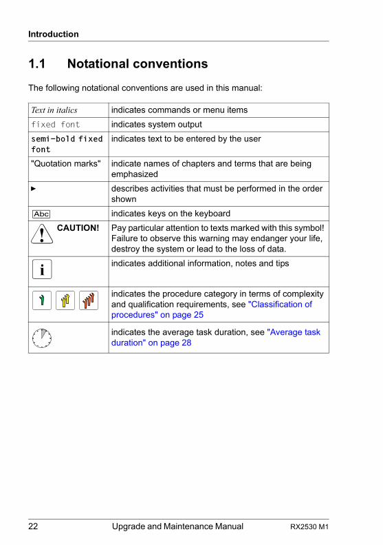
The following notational conventions are used in this manual:
Text in italics indicates commands or menu items
fixed font indicates system output
semi-bold fixed font
indicates text to be entered by the user
"Quotation marks" indicate names of chapters and terms that are being emphasized
Ê describes activities that must be performed in the order shown
[Abc] indicates keys on the keyboard
V CAUTION! Pay particular attention to texts marked with this symbol! Failure to observe this warning may endanger your life, destroy the system or lead to the loss of data.
I indicates additional information, notes and tips
indicates the procedure category in terms of complexity and qualification requirements, see "Classification of procedures" on page 25
indicates the average task duration, see "Average task duration" on page 28
RX2530 M1 Upgrade and Maintenance Manual 23
2 Before you start
Before you start any upgrade or maintenance task, please proceed as follows:
Ê Carefully read the safety instructions in chapter "Important information" on page 33.
Ê Make sure that all necessary manuals are available. Refer to the documentation overview in section "Documents you need at hand" on page 31. Print the PDF files if required.
Ê Make yourself familiar with the procedure categories introduced in section "Classification of procedures" on page 25.
Ê Ensure that all required tools are available according to section "Tools you need at hand" on page 29.
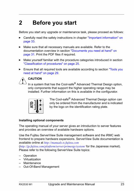
V CAUTION
In a system that has the Cool-safe® Advanced Thermal Design option, only components that support the higher operating range may be installed. Further information on this is available in the configurator.
Installing optional components
The operating manual of your server gives an introduction to server features and provides an overview of available hardware options.
Use the Fujitsu ServerView Suite management software and the iRMC web frontend to prepare hardware expansions. ServerView Suite documentation is available online at http://manuals.ts.fujitsu.com (http://jp.fujitsu.com/platform/server/primergy/system/ for the Japanese market). Please refer to the following ServerView Suite topics:
– Operation– Virtualization– Maintenance– Out-Of-Band Management
The Cool-safe® Advanced Thermal Design option can only be ordered from the manufacturer and is indicated by the logo on the identification rating plate.
24 Upgrade and Maintenance Manual RX2530 M1
Before you start
I For the latest information on hardware options, refer to your server’s hardware configurator available online at the following address:for the global market:http://ts.fujitsu.com/products/standard_servers/index.htm for the Japanese market:http://jp.fujitsu.com/platform/server/primergy/system/
Please contact your local Fujitsu customer service partner for details on how to order expansion kits or spare parts. Use the Fujitsu Illustrated Spares Catalog to identify the required spare part and obtain technical data and order information. Illustrated Spares catalogs are available online at http://manuals.ts.fujitsu.com/illustrated_spares (global market only).
Replacing a defective component
The Global Error indicator on the front of the server reports defective hardware components that need to be replaced. For further information on the controls and indicators of your server, refer to the operating manual of your server and section "Connectors and indicators" on page 358.
If the system has been powered off in order to replace a non-hot plug unit, a system of PRIMERGY diagnostic indicators guides you to the defective component. The "Indicate CSS" button enables the indicator next to the defective component even if the server has been switched off and disconnected from the mains. For further information, please refer to sections "Using diagnostics information" on page 45 and "Indicators on the front panel" on page 365.
If the defective component is a customer replaceable unit included in the CSS concept (Customer Self Service, only available for global market), the CSS indicator on the front side of the server will light up.
It is recommended to prepare local maintenance tasks using remote diagnostics procedures, as described in the "ServerView Suite Local Service Concept (LSC)" manual.
RX2530 M1 Upgrade and Maintenance Manual 25
Before you start
2.1 Classification of procedures
The complexity of maintenance procedures varies significantly. Procedures have been assigned to one of three unit categories, indicating the level of difficulty and required qualification.
At the beginning of each procedure, the involved unit type is indicated by one of the symbols introduced in this section.
I Please ask your local Fujitsu service center for more detailed information.
2.1.1 Customer Replaceable Units (CRU)
Customer Replaceable Units are intended for customer self service and may be installed or replaced as hot-plug components during operation.
I Components that the customer is entitled to replace may differ according to the service form in his country.
Hot-plug components increase system availability and guarantee a high degree of data integrity and fail-safe performance. Procedures can be carried out without shutting down the server or going offline.
Components that are handled as Customer Replaceable Units
– Hot-plug power supply units– Hot-plug fan modules– Hot-plug HDD/SSD modules
Peripherals that are handled as Customer Replaceable Units
– Keyboard– Mouse
Customer Replaceable Units (CRU)
26 Upgrade and Maintenance Manual RX2530 M1
Before you start
2.1.2 Upgrade and Repair Units (URU)
Upgrade and Repair Units are non hot-plug components that can be ordered separately to be installed as options (Upgrade Units) or are available to the customer through customer self service (Repair Units).
I Server management error messages and diagnostic indicators on the front panel and system board will report defective Upgrade and Repair Units as customer replaceable CSS components.
Upgrade and repair procedures involve shutting down and opening the server.
V CAUTION!
The device may be seriously damaged or cause damage if it is opened without authorization or if repairs are attempted by unauthorized and untrained personnel.
Components that are handled as Upgrade Units
– Processors (upgrade kits)– Optical disk drives– Expansion cards– Flash backup units– Memory modules– SATA DOM– iRMC microSD card
Components that are handled solely as Repair Units
– CMOS battery
Upgrade and Repair Units (URU)
RX2530 M1 Upgrade and Maintenance Manual 27
Before you start
2.1.3 Field Replaceable Units (FRU)
Removing and installing Field Replaceable Units involves complex maintenance procedures on integral server components. Procedures will require shutting down, opening and disassembling the server.
V CAUTION!
Maintenance procedures involving Field Replaceable Units must be performed exclusively by Fujitsu service personnel or technicians trained by Fujitsu. Please note that unauthorized interference with the system will void the warranty and exempt the manufacturer from all liability.
Components that are handled as Field Replaceable Units
– Processor (replacement)– SAS / SATA backplanes– Front panel module– System board– Trusted Platform Module (TPM)– USB Flash Module (UFM)
I Please ask your local Fujitsu service center for more detailed information.
Field Replaceable Units (FRU)
28 Upgrade and Maintenance Manual RX2530 M1
Before you start
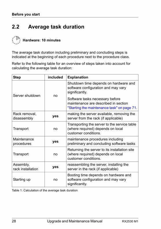
2.2 Average task duration
The average task duration including preliminary and concluding steps is indicated at the beginning of each procedure next to the procedure class.
Refer to the following table for an overview of steps taken into account for calculating the average task duration:
Hardware: 10 minutes
Step included Explanation
Server shutdown no
Shutdown time depends on hardware and software configuration and may vary significantly.
Software tasks necessary before maintenance are described in section "Starting the maintenance task" on page 71.
Rack removal, disassembly
yesmaking the server available, removing the server from the rack (if applicable)
Transport noTransporting the server to the service table (where required) depends on local customer conditions.
Maintenance procedures
yesmaintenance procedures including preliminary and concluding software tasks
Transport noReturning the server to its installation site (where required) depends on local customer conditions.
Assembly, rack installation
yesreassembling the server, installing the server in the rack (if applicable)
Starting up noBooting time depends on hardware and software configuration and may vary significantly.
Table 1: Calculation of the average task duration
RX2530 M1 Upgrade and Maintenance Manual 29
Before you start
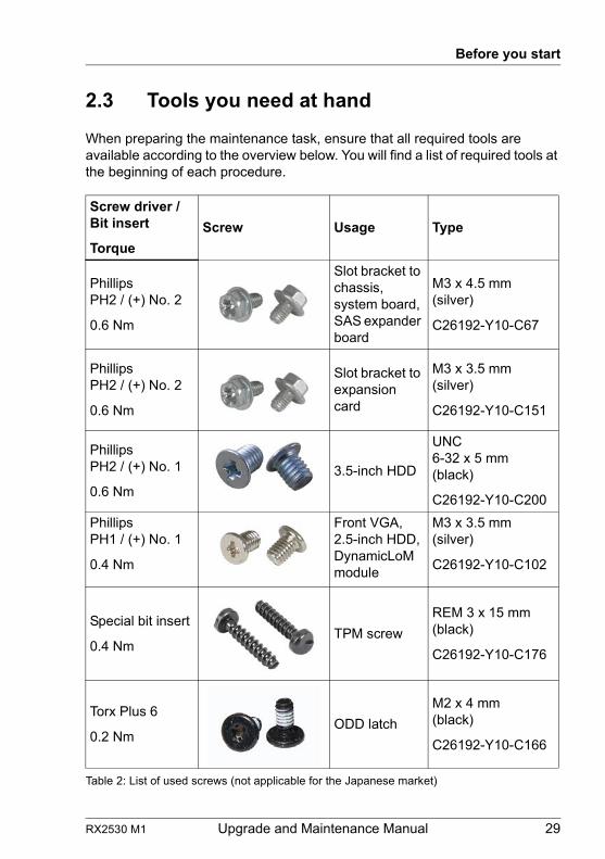
2.3 Tools you need at hand
When preparing the maintenance task, ensure that all required tools are available according to the overview below. You will find a list of required tools at the beginning of each procedure.
Screw driver / Bit insert
Torque
Screw Usage Type
PhillipsPH2 / (+) No. 2
0.6 Nm
Slot bracket to chassis, system board, SAS expander board
M3 x 4.5 mm(silver)
C26192-Y10-C67
PhillipsPH2 / (+) No. 2
0.6 Nm
Slot bracket to expansion card
M3 x 3.5 mm(silver)
C26192-Y10-C151
PhillipsPH2 / (+) No. 1
0.6 Nm
3.5-inch HDD
UNC6-32 x 5 mm(black)
C26192-Y10-C200
PhillipsPH1 / (+) No. 1
0.4 Nm
Front VGA, 2.5-inch HDD, DynamicLoM module
M3 x 3.5 mm(silver)
C26192-Y10-C102
Special bit insert
0.4 NmTPM screw
REM 3 x 15 mm(black)
C26192-Y10-C176
Torx Plus 6
0.2 NmODD latch
M2 x 4 mm(black)
C26192-Y10-C166
Table 2: List of used screws (not applicable for the Japanese market)
30 Upgrade and Maintenance Manual RX2530 M1
Before you start
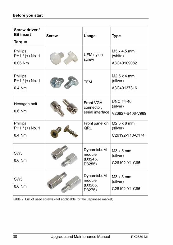
PhillipsPH1 / (+) No. 1
0.06 Nm
UFM nylon screw
M3 x 4.5 mm(white)
A3C40109082
PhillipsPH1 / (+) No. 1
0.4 Nm
TFM
M2.5 x 4 mm(silver)
A3C40137316
Hexagon bolt
0.6 Nm
Front VGA connector, serial interface
UNC #4-40(silver)
V26827-B408-V989
PhillipsPH1 / (+) No. 1
0.4 Nm
Front panel on QRL
M2.5 x 8 mm(silver)
C26192-Y10-C174
SW5
0.6 Nm
DynamicLoM module (D3245, D3255)
M3 x 5 mm(silver)
C26192-Y1-C65
SW5
0.6 Nm
DynamicLoM module (D3265, D3275)
M3 x 8 mm(silver)
C26192-Y1-C66
Screw driver / Bit insert
Torque
Screw Usage Type
Table 2: List of used screws (not applicable for the Japanese market)
RX2530 M1 Upgrade and Maintenance Manual 31
Before you start
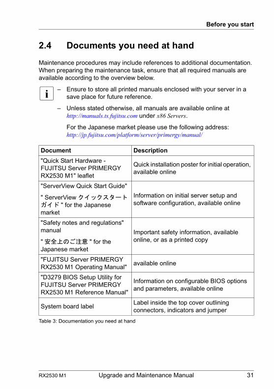
2.4 Documents you need at hand
Maintenance procedures may include references to additional documentation. When preparing the maintenance task, ensure that all required manuals are available according to the overview below.
I – Ensure to store all printed manuals enclosed with your server in a save place for future reference.
– Unless stated otherwise, all manuals are available online at http://manuals.ts.fujitsu.com under x86 Servers.
For the Japanese market please use the following address: http://jp.fujitsu.com/platform/server/primergy/manual/
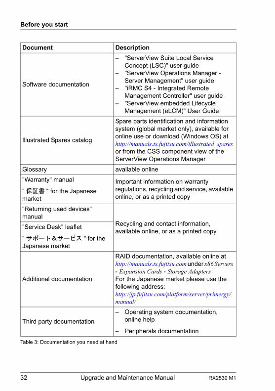
Document Description
"Quick Start Hardware - FUJITSU Server PRIMERGY RX2530 M1" leaflet
Quick installation poster for initial operation, available online
"ServerView Quick Start Guide"
" ServerView クイックスタートガイド " for the Japanese market
Information on initial server setup and software configuration, available online
"Safety notes and regulations" manual
" 安全上のご注意 " for the Japanese market
Important safety information, available online, or as a printed copy
"FUJITSU Server PRIMERGY RX2530 M1 Operating Manual"
available online
"D3279 BIOS Setup Utility for FUJITSU Server PRIMERGY RX2530 M1 Reference Manual"
Information on configurable BIOS options and parameters, available online
System board labelLabel inside the top cover outlining connectors, indicators and jumper
Table 3: Documentation you need at hand
32 Upgrade and Maintenance Manual RX2530 M1
Before you start
Software documentation
– "ServerView Suite Local Service Concept (LSC)" user guide
– "ServerView Operations Manager - Server Management" user guide
– "iRMC S4 - Integrated Remote Management Controller" user guide
– "ServerView embedded Lifecycle Management (eLCM)" User Guide
Illustrated Spares catalog
Spare parts identification and information system (global market only), available for online use or download (Windows OS) at http://manuals.ts.fujitsu.com/illustrated_spares or from the CSS component view of the ServerView Operations Manager
Glossary available online
"Warranty" manual
" 保証書 " for the Japanese market
Important information on warranty regulations, recycling and service, available online, or as a printed copy
"Returning used devices" manual
Recycling and contact information, available online, or as a printed copy
"Service Desk" leaflet
" サポート&サービス " for the Japanese market
Additional documentation
RAID documentation, available online at http://manuals.ts.fujitsu.com under x86 Servers - Expansion Cards - Storage AdaptersFor the Japanese market please use the following address: http://jp.fujitsu.com/platform/server/primergy/manual/
Third party documentation
– Operating system documentation, online help
– Peripherals documentation
Document Description
Table 3: Documentation you need at hand
RX2530 M1 Upgrade and Maintenance Manual 33
3 Important information
V CAUTION!
Before installing and starting up a device, please observe the safety instructions listed in the following section. This will help you to avoid making serious errors that could impair your health, damage the device and endanger the data base.
3.1 Safety instructions
I The following safety instructions are also provided in the manual "Safety Notes and Regulations" or " 安全上のご注意 ".
This device meets the relevant safety regulations for IT equipment. If you have any questions about whether you can install the server in the intended environment, please contact your sales outlet or our customer service team.
● The actions described in this manual shall be performed by technical specialists. A technical specialist is a person who is trained to install the server including hardware and software.
● Repairs to the device that do not relate to CSS failures shall be performed by service personnel. Please note that unauthorized interference with the system will void the warranty and exempt the manufacturer from all liability.
● Any failure to observe the guidelines in this manual, and any improper repairs could expose the user to risks (electric shock, energy hazards, fire hazards) or damage the equipment.
● Before installing/removing internal options to/from the server, turn off the server, all peripheral devices, and any other connected devices. Also unplug all power cords from the power outlet. Failure to do so can cause electric shock or damage.
Before starting up
● During installation and before operating the device, observe the instructions on environmental conditions for your device.
● If the device is brought in from a cold environment, condensation may form both inside and on the outside of the device.
34 Upgrade and Maintenance Manual RX2530 M1
Important information
Wait until the device has acclimatized to room temperature and is absolutely dry before starting it up. Material damage may be caused to the device if this requirement is not observed.
● Transport the device only in the original packaging or in packaging that protects it from knocks and jolts.For the Japanese market, transporting the device in its original packaging does not apply.
Installation and operation
● This unit should not be operated in ambient temperatures above 35 °C. For servers with Cool-safe® Advanced Thermal Design the ambient temperature can increase to 40 °C.
● If the unit is integrated into an installation that draws power from an industrial power supply network with an IEC309 connector, the power supply's fuse protection must comply with the requirements for non-industrial power supply networks for type A connectors.
● The unit automatically adjusts itself to a mains voltage in a range of 100 V - 240 V. Ensure that the local mains voltage lies within these limits.
● This device must only be connected to properly grounded power outlets or connected to the grounded rack internal power distribution system with tested and approved power cords.
● Ensure that the device is connected to a properly grounded power outlet close to the device.
● Ensure that the power sockets on the device and the properly grounded power outlets are easily accessible.
● The On/Off button or the main power switch (if present) does not isolate the device from the mains power supply. In case of repair or servicing disconnect the device completely from the mains power supply, unplug all power plugs from the properly grounded power outlets.
● Always connect the server and the attached peripherals to the same power circuit. Otherwise you run the risk of losing data if, for example, the server is still running but a peripheral device (e.g. memory subsystem) fails during a power outage.
● Data cables must be adequately shielded.
RX2530 M1 Upgrade and Maintenance Manual 35
Important information
● Ethernet cabling has to comply with EN 50173 and EN 50174-1/2 standards or ISO/IEC 11801 standard respectively. The minimum requirement is a Category 5 shielded cable for 10/100 Ethernet, or a Category 5e cable for Gigabit Ethernet.
● Route the cables in such a way that they do not create a potential hazard (make sure no-one can trip over them) and that they cannot be damaged. When connecting the server, refer to the relevant instructions in this manual.
● Never connect or disconnect data transmission lines during a storm (risk of lightning hazard).
● Make sure that no objects (e.g. jewelry, paperclips etc.) or liquids can get inside the server (risk of electric shock, short circuit).
● In emergencies (e.g. damaged casing, controls or cables, penetration of liquids or foreign bodies), contact the system administrator or your customer service team. Only disconnect the system from the mains power supply if there is no risk of harming yourself.
● Proper operation of the system (in accordance with IEC 60950-1 resp. EN 60950-1) is only ensured if the casing is completely assembled and the rear covers for the installation slots have been fitted (electric shock, cooling, fire protection, interference suppression).
● Only install system expansions that satisfy the requirements and rules governing safety and electromagnetic compatibility and those relating to telecommunication terminals. If you install other expansions, they may damage the system or violate the safety regulations. Information on which system expansions are approved for installation can be obtained from our customer service center or your sales outlet.
● The components marked with a warning notice (e.g. lightning symbol) may only be opened, removed or exchanged by authorized, qualified personnel. Exception: CSS components can be replaced.
● The warranty is void if the server is damaged during installation or replacement of system expansions.
● Only set screen resolutions and refresh rates that are specified in the operating manual for the monitor. Otherwise, you may damage your monitor. If you are in any doubt, contact your sales outlet or customer service center.
● Before installing/removing internal options to/from the server, turn off the server, all peripheral devices, and any other connected devices. Also unplug all power cords from the outlet. Failure to do so can cause electric shock.
36 Upgrade and Maintenance Manual RX2530 M1
Important information
● Do not damage or modify internal cables or devices. Doing so may cause a device failure, fire, or electric shock and will void the warranty and exempt the manufacturer from all liability.
● Devices inside the server remain hot after shutdown. Wait for a while after shutdown before installing or removing internal options.
● The circuit boards and soldered parts of internal options are exposed and can be damaged by static electricity. To ensure reliable protection, if you are wearing an earthing band on your wrist when working with this type of module, connect it to an unpainted, conducting metal part of the system.
● Do not touch the circuitry on boards or soldered parts. Hold the metallic areas or the edges of the circuit boards.
● Install the screw removed during installation/detaching internal options in former device/position. To use a screw of the different kind can cause a breakdown of equipment.
● The installation indicated on this document is sometimes changed to the kind of possible options without notice.
Batteries
● Incorrect replacement of batteries may lead to a risk of explosion. The batteries may only be replaced with identical batteries or with a type recommended by the manufacturer.
● Do not throw batteries into the trash can.
● Batteries must be disposed of in accordance with local regulations concerning special waste.
● Make sure that you insert the battery the right way round.
● The battery used in this device may present a fire or chemical burn hazard if mistreated. Do not disassemble, heat about 100 °C (212F), or incinerate the battery.
● All batteries containing pollutants are marked with a symbol (a crossed-out garbage can). In addition, the marking is provided with the chemical symbol of the heavy metal decisive for the classification as a pollutant:
Cd Cadmium Hg Mercury Pb Lead
RX2530 M1 Upgrade and Maintenance Manual 37
Important information
Working with CDs/DVDs/BDs and optical drives
When working with devices with optical drives, these instructions must be followed.
V CAUTION!
● Only use CDs/DVDs/BDs that are in perfect condition, in order to prevent data loss, equipment damage and injury.
● Check each CD/DVD/BD for damage, cracks, breakages etc. before inserting it in the drive.
Note that any additional labels applied may change the mechanical properties of a CD/DVD/BD and cause imbalance.
Damaged and imbalanced CDs/DVDs/BDs can break at high drive speeds (data loss).
Under certain circumstances, sharp CD/DVD/BD fragments can pierce the cover of the optical drive (equipment damage) and can fly out of the device (danger of injury, particularly to uncovered body parts such as the face or neck).
● High humidity and airborne dust levels are to be avoided. Electric shocks and/or server failures may be caused by liquids such as water, or metallic items, such as paper clips, entering a drive.
● Shocks and vibrations are also to be avoided.
● Do not insert any objects other than the specified CDs/DVDs/BDs.
● Do not pull on, press hard, or otherwise handle the CD/DVD/BD tray roughly.
● Do not disassemble the optical drive.
● Before use, clean the optical disk tray using a soft, dry cloth.
● As a precaution, remove disks from the optical drive when the drive is not to be used for a long time. Keep the optical disk tray closed to prevent foreign matter, such as dust, from entering the optical drive.
● Hold CDs/DVDs/BDs by their edges to avoid contact with the disk surface.
38 Upgrade and Maintenance Manual RX2530 M1
Important information
● Do not contaminate the CD/DVD/BD surface with fingerprints, oil, dust, etc. If dirty, clean with a soft, dry cloth, wiping from the center to the edge. Do not use benzene, thinners, water, record sprays, antistatic agents, or silicone-impregnated cloth.
● Be careful not to damage the CD/DVD/BD surface.
● Keep the CDs/DVDs/BDs away from heat sources.
● Do not bend or place heavy objects on CDs/DVDs/BDs.
● Do not write with ballpoint pen or pencil on the label (printed) side.
● Do not attach stickers or similar to the label side. Doing so may cause rotational eccentricity and abnormal vibrations.
● When a CD/DVD/BD is moved from a cold place to a warm place, moisture condensation on the CD/DVD/BD surface can cause data read errors. In this case, wipe the CD/DVD/BD with a soft, dry cloth then let it air dry. Do not dry the CD/DVD/BD using devices such as a hair dryer.
● To avoid dust, damage, and deformation, keep the CD/DVD/BD in its case whenever it is not in use.
● Do not store CDs/DVDs/BDs at high temperatures. Areas exposed to prolonged direct sunlight or near heating appliances are to be avoided.
I You can prevent damage from the optical drive and the CDs/DVDs/BDs, as well as premature wear of the disks, by observing the following suggestions:
– Only insert disks in the drive when needed and remove them after use.
– Store the disks in suitable sleeves.– Protect the disks from exposure to heat and direct sunlight.
Laser information
The optical drive complies with IEC 60825-1 laser class 1.
V CAUTION!
The optical drive contains a light-emitting diode (LED), which under certain circumstances produces a laser beam stronger than laser class 1. Looking directly at this beam is dangerous.
Never remove parts of the optical drive casing!
RX2530 M1 Upgrade and Maintenance Manual 39
Important information
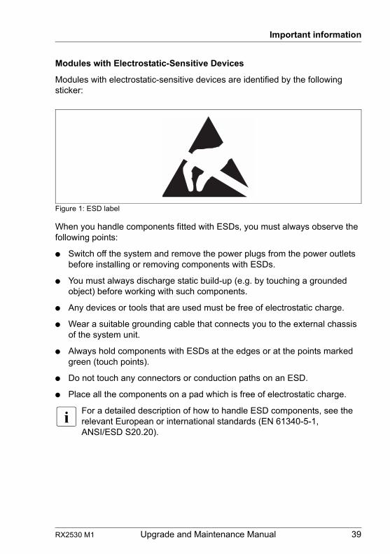
Modules with Electrostatic-Sensitive Devices
Modules with electrostatic-sensitive devices are identified by the following sticker:
Figure 1: ESD label
When you handle components fitted with ESDs, you must always observe the following points:
● Switch off the system and remove the power plugs from the power outlets before installing or removing components with ESDs.
● You must always discharge static build-up (e.g. by touching a grounded object) before working with such components.
● Any devices or tools that are used must be free of electrostatic charge.
● Wear a suitable grounding cable that connects you to the external chassis of the system unit.
● Always hold components with ESDs at the edges or at the points marked green (touch points).
● Do not touch any connectors or conduction paths on an ESD.
● Place all the components on a pad which is free of electrostatic charge.
I For a detailed description of how to handle ESD components, see the relevant European or international standards (EN 61340-5-1, ANSI/ESD S20.20).
40 Upgrade and Maintenance Manual RX2530 M1
Important information
Transporting the server
● Only transport the server in its original packaging or in packaging that protects it from impacts and jolts. For the Japanese market, transporting the device in its original packaging does not apply.
● Do not unpack the server until it is at its installation location.
● If you need to lift or transport the server, ask other people to help you.
● Never lift or carry the device by the handles on the front panel.
Notes on installing the server in the rack
● For safety reasons, at least two people are required to install the server in the rack because of its weight and size.
(For the Japanese market, please refer to " 安全上のご注意 ".)
● Never lift the server into the rack using the handles on the front panel.
● When connecting and disconnecting cables, observe the relevant instructions in the "Important Information" chapter of the technical manual for the corresponding rack. The technical manual is supplied with the corresponding rack.
● When installing the rack, make sure that the anti-tilt protection is correctly fitted.
● For safety reasons, no more than one unit may be removed from the rack at any one time during installation and maintenance work.
● If several units are simultaneously removed from the rack, there is a risk that the rack could tip over.
● The rack must be connected to the power supply by an authorized specialist (electrician).
● If the server is integrated into an installation that draws power from an industrial power supply network with an IEC309 type connector, the power supply's fuse protection must comply with the requirements for non-industrial power supply networks for the type A connector.
RX2530 M1 Upgrade and Maintenance Manual 41
Important information
3.2 ENERGY STAR
3.3 CE conformity
Products that have been certified compliant with ENERGY STAR and identified as such are in full compliance with the specification at shipping. Note that energy consumption can be affected by software that is installed or any changes that are made to the hardware configuration or BIOS or energy options subsequently. In such cases, the properties guaranteed by ENERGY STAR can no longer be assured.
The "ServerView Operations Manager" user guide contains instructions for reading out measurement values, including those relating to current energy consumption and air temperatures. Either the Performance Monitor or the Task Manager can be used to read out CPU utilization levels.
The system complies with the requirements of the EC directives 2004/108/EC regarding "Electromagnetic Compatibility" and 2006/95/EC "Low Voltage Directive" and the directive of the European Parliament and Council 2011/65/EU. This is indicated by the CE marking (CE = Communauté Européenne).

42 Upgrade and Maintenance Manual RX2530 M1
Important information
3.4 FCC Class A Compliance Statement
If there is an FCC statement on the device, it applies to the products covered in this manual, unless otherwise specified herein. The statement for other products will appear in the accompanying documentation.
NOTE:
This equipment has been tested and found to comply with the limits for a "Class A" digital device, pursuant to Part 15 of the FCC rules and meets all requirements of the Canadian Interference-Causing Equipment Standard ICES-003 for digital apparatus. These limits are designed to provide reasonable protection against harmful interference in a residential installation. This equipment generates, uses and can radiate radio frequency energy and, if not installed and used in strict accordance with the instructions, may cause harmful interference to radio communications. However, there is no warranty that interference will not occur in a particular installation. If this equipment does cause harmful interference to radio or television reception, which can be determined by turning the equipment off and on, the user is encouraged to try to correct the interference by one or more of the following measures:
● Reorient or relocate the receiving antenna.
● Increase the separation between equipment and the receiver.
● Connect the equipment into an outlet on a circuit different from that to which the receiver is connected.
● Consult the dealer or an experienced radio/TV technician for help.
Fujitsu is not responsible for any radio or television interference caused by unauthorized modifications of this equipment or the substitution or attachment of connecting cables and equipment other than those specified by Fujitsu. The correction of interferences caused by such unauthorized modification, substitution or attachment will be the responsibility of the user.
The use of shielded I/O cables is required when connecting this equipment to any and all optional peripheral or host devices. Failure to do so may violate FCC and ICES rules.
WARNING:
This is a class A product. In a domestic environment this product may cause radio interference in which case the user may be required to take adequate measures.

RX2530 M1 Upgrade and Maintenance Manual 43
Important information
3.5 Environmental protection
Environmentally-friendly product design and development
This product has been designed in accordance with the Fujitsu standard for "environmentally friendly product design and development". This means that key factors such as durability, selection and labeling of materials, emissions, packaging, ease of dismantling and recycling have been taken into account.
This saves resources and thus reduces the harm done to the environment. Further information can be found at:
– http://ts.fujitsu.com/products/standard_servers/index.html (for the global market)– http://jp.fujitsu.com/platform/server/primergy/concept/ (for the Japanese
market)
Energy-saving information
Devices that do not need to be constantly switched on should be switched off until they are needed as well as during long breaks and after completion of work.
Packaging information
This packaging information doesn’t apply to the Japanese market.
Do not throw away the packaging. You may need it later for transporting the system. If possible, the equipment should only be transported in its original packaging.
Information on handling consumables
Please dispose of printer consumables and batteries in accordance with the applicable national regulations.
In accordance with EU directives, batteries must not be disposed of with unsorted domestic waste. They can be returned free of charge to the manufacturer, dealer or an authorized agent for recycling or disposal.
All batteries containing pollutants are marked with a symbol (a crossed-out garbage can). They are also marked with the chemical symbol for the heavy metal that causes them to be categorized as containing pollutants:
Cd CadmiumHg MercuryPb Lead

44 Upgrade and Maintenance Manual RX2530 M1
Important information
Labels on plastic casing parts
Please avoid sticking your own labels on plastic parts wherever possible, since this makes it difficult to recycle them.
Returns, recycling and disposal
Please handle returns, recycling and disposal in accordance with local regulations.
Details regarding the return and recycling of devices and consumables within Europe can also be found in the "Returning used devices" manual, via your local Fujitsu branch or from our recycling center in Paderborn:
Fujitsu Technology SolutionsRecycling CenterD-33106 Paderborn
Tel. +49 5251 525 1410Fax +49 5251 525 32 1410
The device must not be disposed of with domestic waste. This device is labeled in compliance with European directive 2002/96/EC on waste electrical and electronic equipment (WEEE).
This directive sets the framework for returning and recycling used equipment and is valid across the EU. When returning your used device, please use the return and collection systems available to you. Further information can be found at http://ts.fujitsu.com/recycling.
RX2530 M1 Upgrade and Maintenance Manual 45
4 Basic hardware procedures
4.1 Using diagnostics information
Use the Fujitsu ServerView Suite management software to plan the upgrade or replacement of hardware components. Please refer to the following ServerView Suite topics:
– Operation– Maintenance
It is recommended to prepare local maintenance tasks using remote diagnostics procedures, as described in the "ServerView Suite Local Service Concept (LSC)" manual.
Please contact your local Fujitsu customer service partner for details on the service concept and on how to order expansion kits or spare parts. Use the Fujitsu Illustrated Spares Catalog to identify the required spare part and obtain technical data and order information. Illustrated Spares catalogs are available online at http://manuals.ts.fujitsu.com/illustrated_spares (global market only).
Perform the following diagnostics procedures to identify defective servers and components.
4.1.1 Locating the defective server
When working in a datacenter environment, switch on the ID indicator on the front and rear connector panels of the server for easy identification.
Ê Press the ID button on the front panel, use the iRMC web frontend or the ServerView Operation Manager user interface to switch on the system identification LEDs.
I For further information, refer to the "ServerView Suite Local Service Concept (LSC)" manual and the "Integrated Remote Management Controller" user guide.
Ê When using ServerView Operations Manager to toggle the ID indicator, choose Single System View and press the Locate button.
Ê Remember to switch off the ID indicator after the maintenance task has been concluded successfully.
46 Upgrade and Maintenance Manual RX2530 M1
Basic hardware procedures
4.1.2 Determining the error class
The Local Service Concept (LSC) allows you to identify defective server components. Failure events are assigned to one of two error classes:
– Global Error events that need to be resolved by maintenance personnel
– Customer Self Service (CSS) error events that may be resolved by operating personnel
Global Error and CSS LEDs indicate, if the defective component is a customer replaceable unit or if maintenance personnel needs to be dispatched to replace the part.
I The indicators also light up in standby mode and after a server restart due to a power failure.
4.1.2.1 Global Error indicator
Ê Check the Global Error indicator on the front panel of the server.
Ê For further diagnostics, proceed as follows:
– Hardware errors:
Check the System Event Log (SEL) as described in section "Viewing the SEL" on page 92.
– Software / agent related errors:
Check the ServerView System Monitor, available on Windows or Linux based servers with ServerView agents installed.
I For further information, please refer to the "ServerView System Monitor" user guide.
4.1.2.2 Customer Self Service (CSS) indicator
Ê Check the CSS indicator on the front panel of the server.
RX2530 M1 Upgrade and Maintenance Manual 47
Basic hardware procedures
4.1.3 Locating the defective component
After determining the error class by the CSS or Global Error indicators (see section "Determining the error class" on page 46) local diagnostic indicators on the system board, HDD modules and power supply units (only slide-in units) allow you to identify the defective component.
I For further information, refer to the "ServerView Suite Local Service Concept (LSC)" manual.
4.1.3.1 Local diagnostic indicators on the system board
Using the Indicate CSS button
Ê Shut down and power off the server.
Ê Disconnect the AC power cord(s) from the system.
I It is mandatory to disconnect power cords in order to use the Indicate CSS functionality.
Ê Press the Indicate CSS button to highlight defective components (see section "Onboard indicators and controls" on page 360).
I In addition to local diagnostic indicators, CSS or Global Error LEDs indicate, if the defective component is a customer replaceable unit or if a service technician needs to be dispatched to replace the part (see section "Determining the error class" on page 46).
If the system has been powered off to replace a non hot-plug unit, a system of PRIMERGY diagnostics indicators guides you to the faulty component.
48 Upgrade and Maintenance Manual RX2530 M1
Basic hardware procedures
4.2 Shutting down the server
V CAUTION!
For further safety information, please refer to chapter "Important information" on page 33.
I This step is only required when upgrading or replacing non-hot plug components.
Ê Inform the system administrator that the server will be shut down and put offline.
Ê Terminate all applications.
Ê Perform the required procedures described in the preliminary steps of each upgrade or maintenance task.
Ê Shut down the server.
I If the system is running an ACPI-compliant operating system, pressing the On / Off button will perform a graceful shutdown.
Ê Switch on the ID indicator on the front and rear connector panels of the server as described in section "Locating the defective server" on page 45.
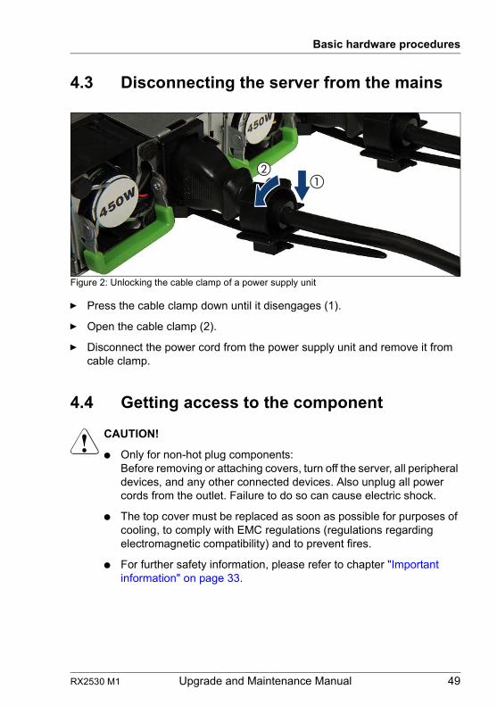
RX2530 M1 Upgrade and Maintenance Manual 49
Basic hardware procedures
4.3 Disconnecting the server from the mains
Figure 2: Unlocking the cable clamp of a power supply unit
Ê Press the cable clamp down until it disengages (1).
Ê Open the cable clamp (2).
Ê Disconnect the power cord from the power supply unit and remove it from cable clamp.
4.4 Getting access to the component
V CAUTION!
● Only for non-hot plug components:Before removing or attaching covers, turn off the server, all peripheral devices, and any other connected devices. Also unplug all power cords from the outlet. Failure to do so can cause electric shock.
● The top cover must be replaced as soon as possible for purposes of cooling, to comply with EMC regulations (regulations regarding electromagnetic compatibility) and to prevent fires.
● For further safety information, please refer to chapter "Important information" on page 33.
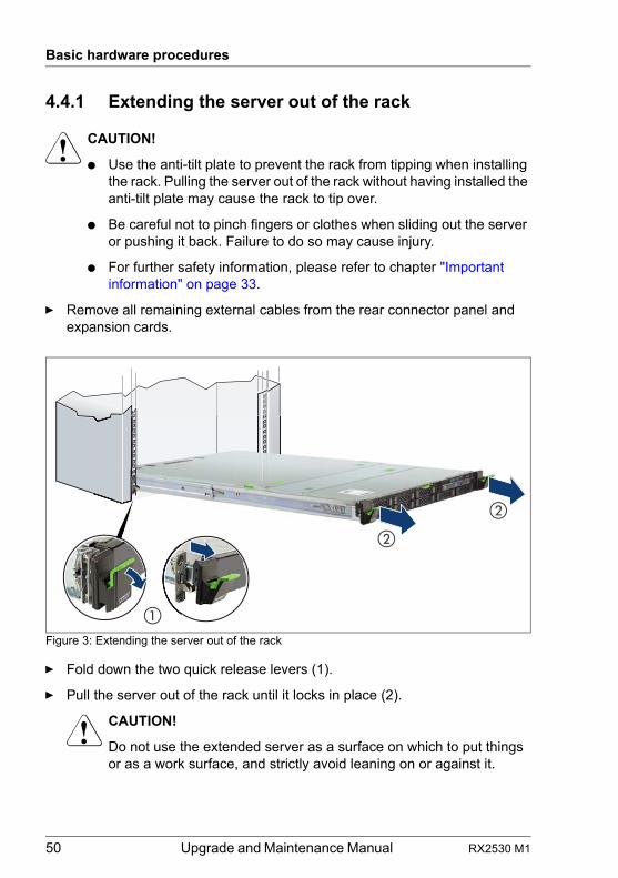
50 Upgrade and Maintenance Manual RX2530 M1
Basic hardware procedures
4.4.1 Extending the server out of the rack
V CAUTION!
● Use the anti-tilt plate to prevent the rack from tipping when installing the rack. Pulling the server out of the rack without having installed the anti-tilt plate may cause the rack to tip over.
● Be careful not to pinch fingers or clothes when sliding out the server or pushing it back. Failure to do so may cause injury.
● For further safety information, please refer to chapter "Important information" on page 33.
Ê Remove all remaining external cables from the rear connector panel and expansion cards.
Figure 3: Extending the server out of the rack
Ê Fold down the two quick release levers (1).
Ê Pull the server out of the rack until it locks in place (2).
V CAUTION!
Do not use the extended server as a surface on which to put things or as a work surface, and strictly avoid leaning on or against it.
�
�
�
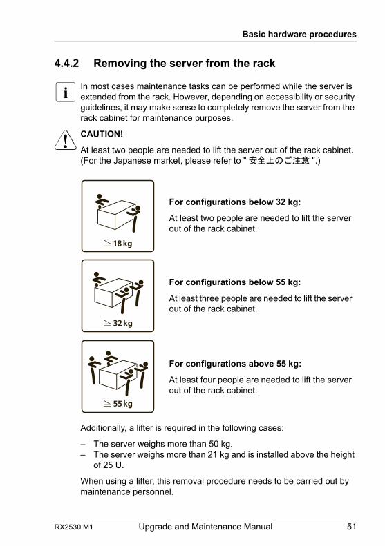
RX2530 M1 Upgrade and Maintenance Manual 51
Basic hardware procedures
4.4.2 Removing the server from the rack
I In most cases maintenance tasks can be performed while the server is extended from the rack. However, depending on accessibility or security guidelines, it may make sense to completely remove the server from the rack cabinet for maintenance purposes.
V CAUTION!
At least two people are needed to lift the server out of the rack cabinet.(For the Japanese market, please refer to " 安全上のご注意 ".)
Additionally, a lifter is required in the following cases:
– The server weighs more than 50 kg.– The server weighs more than 21 kg and is installed above the height
of 25 U.
When using a lifter, this removal procedure needs to be carried out by maintenance personnel.
For configurations below 32 kg:
At least two people are needed to lift the server out of the rack cabinet.
For configurations below 55 kg:
At least three people are needed to lift the server out of the rack cabinet.
For configurations above 55 kg:
At least four people are needed to lift the server out of the rack cabinet.
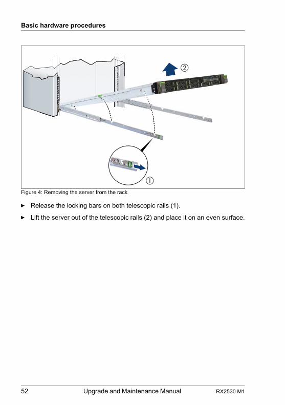
52 Upgrade and Maintenance Manual RX2530 M1
Basic hardware procedures
Figure 4: Removing the server from the rack
Ê Release the locking bars on both telescopic rails (1).
Ê Lift the server out of the telescopic rails (2) and place it on an even surface.
�
�
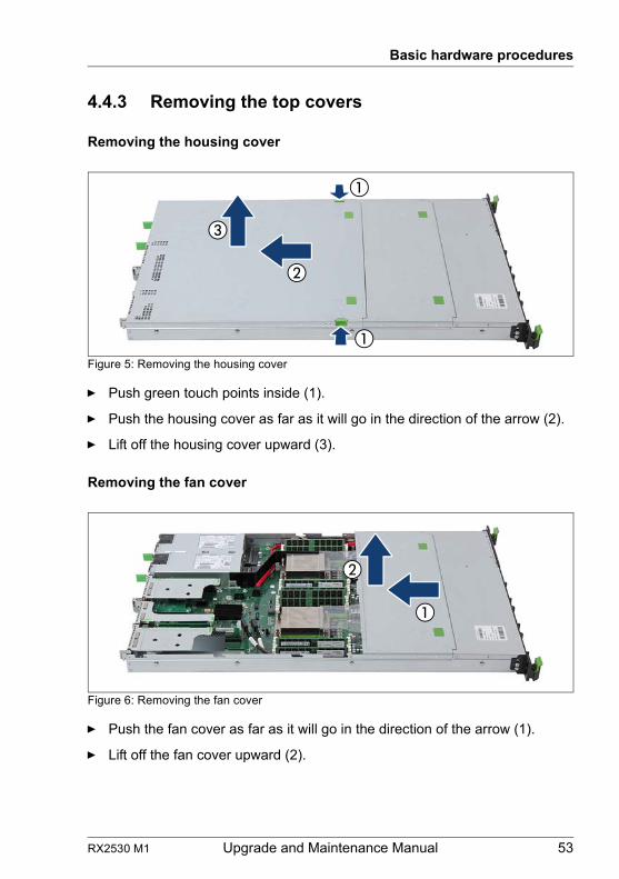
RX2530 M1 Upgrade and Maintenance Manual 53
Basic hardware procedures
4.4.3 Removing the top covers
Removing the housing cover
Figure 5: Removing the housing cover
Ê Push green touch points inside (1).
Ê Push the housing cover as far as it will go in the direction of the arrow (2).
Ê Lift off the housing cover upward (3).
Removing the fan cover
Figure 6: Removing the fan cover
Ê Push the fan cover as far as it will go in the direction of the arrow (1).
Ê Lift off the fan cover upward (2).
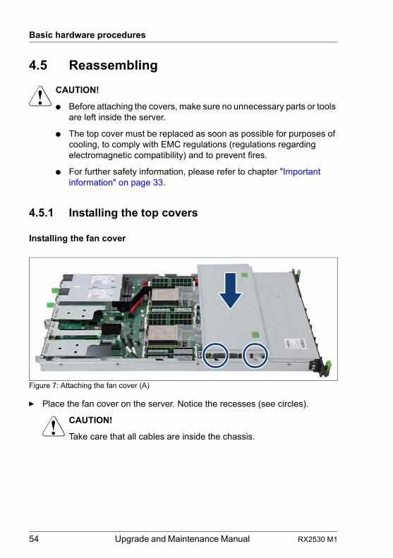
54 Upgrade and Maintenance Manual RX2530 M1
Basic hardware procedures
4.5 Reassembling
V CAUTION!
● Before attaching the covers, make sure no unnecessary parts or tools are left inside the server.
● The top cover must be replaced as soon as possible for purposes of cooling, to comply with EMC regulations (regulations regarding electromagnetic compatibility) and to prevent fires.
● For further safety information, please refer to chapter "Important information" on page 33.
4.5.1 Installing the top covers
Installing the fan cover
Figure 7: Attaching the fan cover (A)
Ê Place the fan cover on the server. Notice the recesses (see circles).
V CAUTION!
Take care that all cables are inside the chassis.
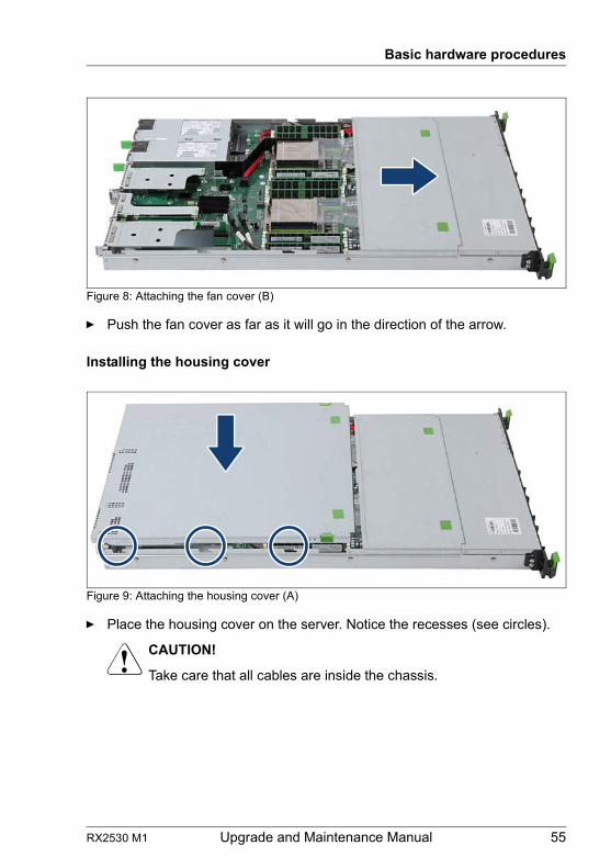
RX2530 M1 Upgrade and Maintenance Manual 55
Basic hardware procedures
Figure 8: Attaching the fan cover (B)
Ê Push the fan cover as far as it will go in the direction of the arrow.
Installing the housing cover
Figure 9: Attaching the housing cover (A)
Ê Place the housing cover on the server. Notice the recesses (see circles).
V CAUTION!
Take care that all cables are inside the chassis.
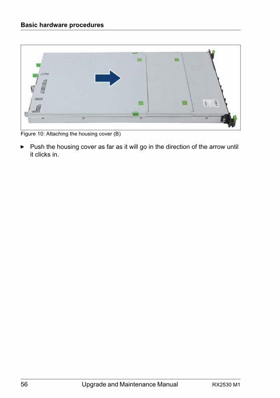
56 Upgrade and Maintenance Manual RX2530 M1
Basic hardware procedures
Figure 10: Attaching the housing cover (B)
Ê Push the housing cover as far as it will go in the direction of the arrow until it clicks in.
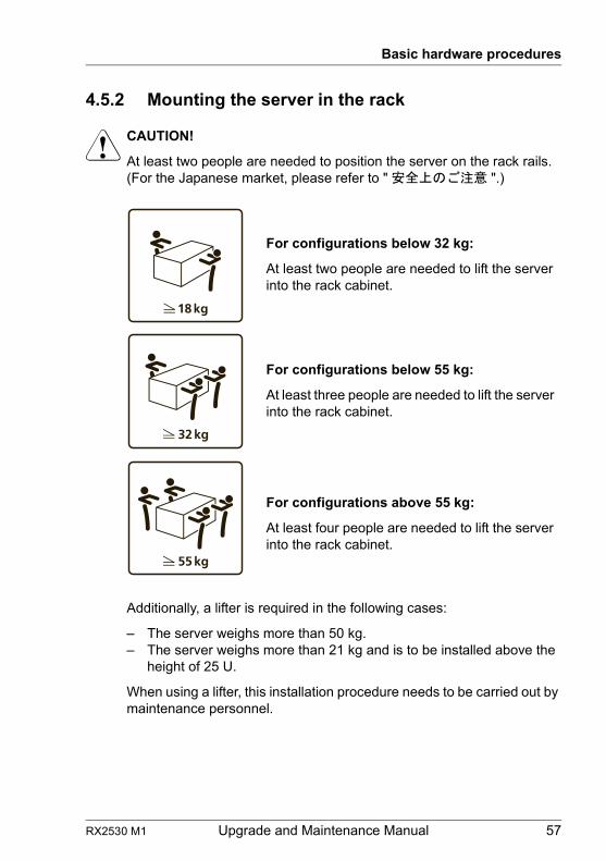
RX2530 M1 Upgrade and Maintenance Manual 57
Basic hardware procedures
4.5.2 Mounting the server in the rack
V CAUTION!
At least two people are needed to position the server on the rack rails. (For the Japanese market, please refer to " 安全上のご注意 ".)
Additionally, a lifter is required in the following cases:
– The server weighs more than 50 kg.– The server weighs more than 21 kg and is to be installed above the
height of 25 U.
When using a lifter, this installation procedure needs to be carried out by maintenance personnel.
For configurations below 32 kg:
At least two people are needed to lift the server into the rack cabinet.
For configurations below 55 kg:
At least three people are needed to lift the server into the rack cabinet.
For configurations above 55 kg:
At least four people are needed to lift the server into the rack cabinet.
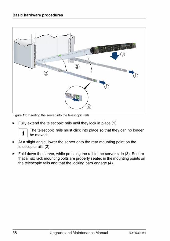
58 Upgrade and Maintenance Manual RX2530 M1
Basic hardware procedures
Figure 11: Inserting the server into the telescopic rails
Ê Fully extend the telescopic rails until they lock in place (1).
I The telescopic rails must click into place so that they can no longer be moved.
Ê At a slight angle, lower the server onto the rear mounting point on the telescopic rails (2).
Ê Fold down the server, while pressing the rail to the server side (3). Ensure that all six rack mounting bolts are properly seated in the mounting points on the telescopic rails and that the locking bars engage (4).
�
�
�
�
�
�
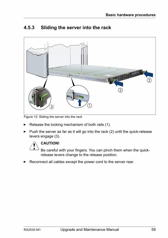
RX2530 M1 Upgrade and Maintenance Manual 59
Basic hardware procedures
4.5.3 Sliding the server into the rack
Figure 12: Sliding the server into the rack
Ê Release the locking mechanism of both rails (1).
Ê Push the server as far as it will go into the rack (2) until the quick-release levers engage (3).
V CAUTION!
Be careful with your fingers. You can pinch them when the quick-release levers change to the release position.
Ê Reconnect all cables except the power cord to the server rear.
�� ��
�
�
��������������
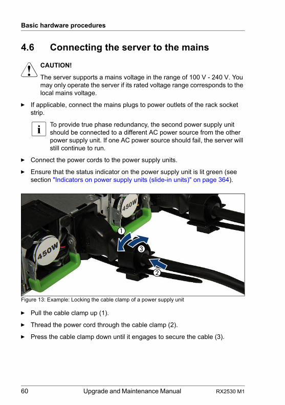
60 Upgrade and Maintenance Manual RX2530 M1
Basic hardware procedures
4.6 Connecting the server to the mains
V CAUTION!
The server supports a mains voltage in the range of 100 V - 240 V. You may only operate the server if its rated voltage range corresponds to the local mains voltage.
Ê If applicable, connect the mains plugs to power outlets of the rack socket strip.
I To provide true phase redundancy, the second power supply unit should be connected to a different AC power source from the other power supply unit. If one AC power source should fail, the server will still continue to run.
Ê Connect the power cords to the power supply units.
Ê Ensure that the status indicator on the power supply unit is lit green (see section "Indicators on power supply units (slide-in units)" on page 364).
Figure 13: Example: Locking the cable clamp of a power supply unit
Ê Pull the cable clamp up (1).
Ê Thread the power cord through the cable clamp (2).
Ê Press the cable clamp down until it engages to secure the cable (3).
RX2530 M1 Upgrade and Maintenance Manual 61
Basic hardware procedures
4.7 Switching on the server
V CAUTION!
● Before switching on the server, make sure the top cover is closed. In order to comply with applicable EMC regulations (regulations on electromagnetic compatibility) and satisfy cooling requirements, the server must not run while the top cover is removed.
● For further safety information, please refer to chapter "Important information" on page 33.
Ê Press the On / Off button to start up the server.
Ê Ensure that the power-on indicator above the On / Off button is lit green.
Ê Perform the required procedures described in the concluding steps of each upgrade or maintenance task.
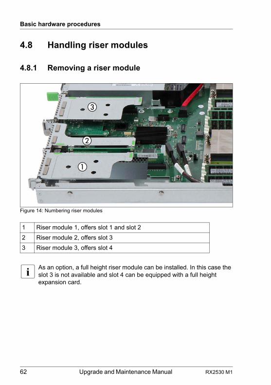
62 Upgrade and Maintenance Manual RX2530 M1
Basic hardware procedures
4.8 Handling riser modules
4.8.1 Removing a riser module
Figure 14: Numbering riser modules
I As an option, a full height riser module can be installed. In this case the slot 3 is not available and slot 4 can be equipped with a full height expansion card.
1 Riser module 1, offers slot 1 and slot 2
2 Riser module 2, offers slot 3
3 Riser module 3, offers slot 4
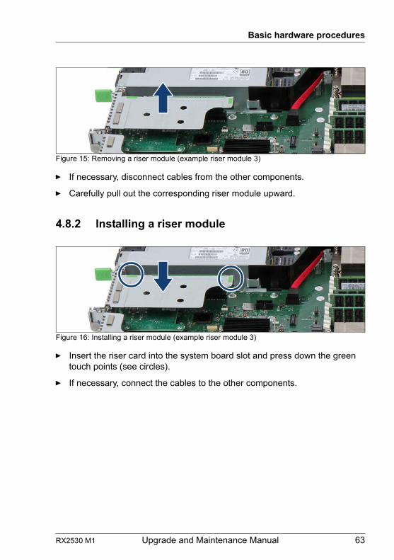
RX2530 M1 Upgrade and Maintenance Manual 63
Basic hardware procedures
Figure 15: Removing a riser module (example riser module 3)
Ê If necessary, disconnect cables from the other components.
Ê Carefully pull out the corresponding riser module upward.
4.8.2 Installing a riser module
Figure 16: Installing a riser module (example riser module 3)
Ê Insert the riser card into the system board slot and press down the green touch points (see circles).
Ê If necessary, connect the cables to the other components.
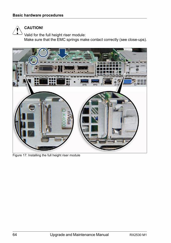
64 Upgrade and Maintenance Manual RX2530 M1
Basic hardware procedures
V CAUTION!
Valid for the full height riser module:Make sure that the EMC springs make contact correctly (see close-ups).
Figure 17: Installing the full height riser module
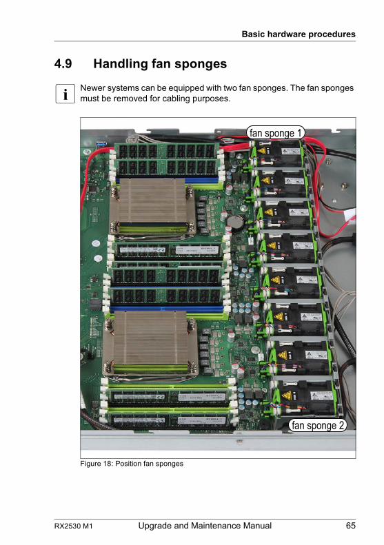
RX2530 M1 Upgrade and Maintenance Manual 65
Basic hardware procedures
4.9 Handling fan sponges
I Newer systems can be equipped with two fan sponges. The fan sponges must be removed for cabling purposes.
Figure 18: Position fan sponges
fan sponge 1
fan sponge 2
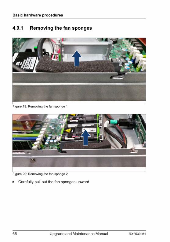
66 Upgrade and Maintenance Manual RX2530 M1
Basic hardware procedures
4.9.1 Removing the fan sponges
Figure 19: Removing the fan sponge 1
Figure 20: Removing the fan sponge 2
Ê Carefully pull out the fan sponges upward.
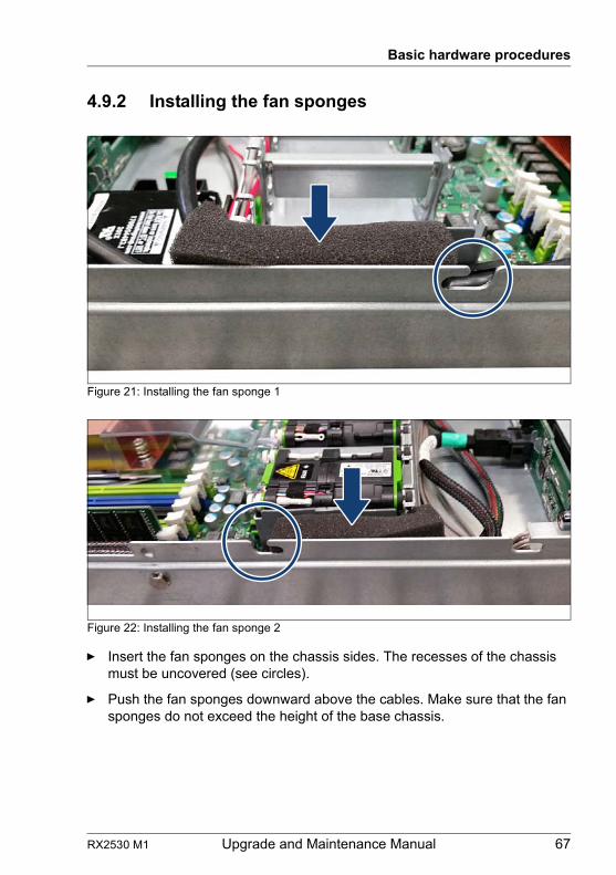
RX2530 M1 Upgrade and Maintenance Manual 67
Basic hardware procedures
4.9.2 Installing the fan sponges
Figure 21: Installing the fan sponge 1
Figure 22: Installing the fan sponge 2
Ê Insert the fan sponges on the chassis sides. The recesses of the chassis must be uncovered (see circles).
Ê Push the fan sponges downward above the cables. Make sure that the fan sponges do not exceed the height of the base chassis.
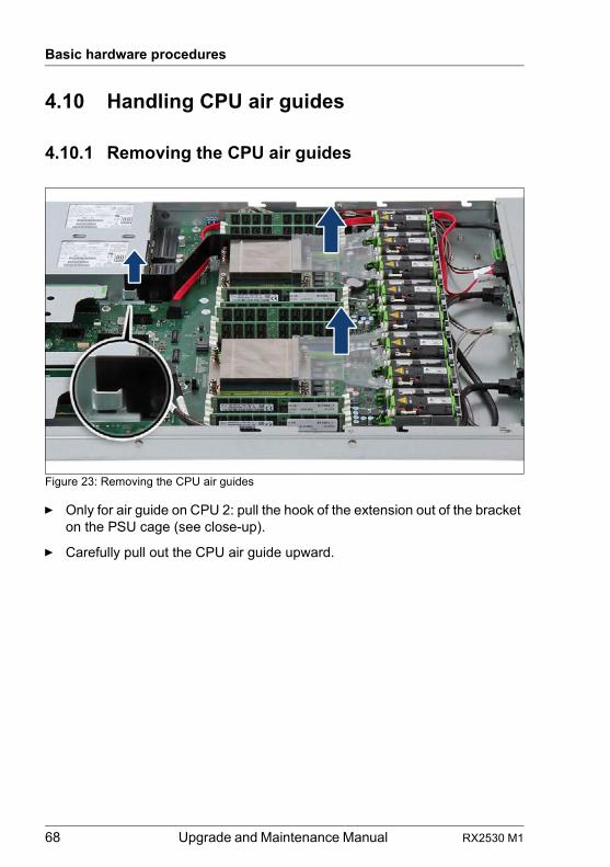
68 Upgrade and Maintenance Manual RX2530 M1
Basic hardware procedures
4.10 Handling CPU air guides
4.10.1 Removing the CPU air guides
Figure 23: Removing the CPU air guides
Ê Only for air guide on CPU 2: pull the hook of the extension out of the bracket on the PSU cage (see close-up).
Ê Carefully pull out the CPU air guide upward.
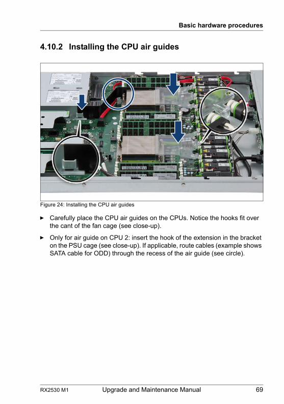
RX2530 M1 Upgrade and Maintenance Manual 69
Basic hardware procedures
4.10.2 Installing the CPU air guides
Figure 24: Installing the CPU air guides
Ê Carefully place the CPU air guides on the CPUs. Notice the hooks fit over the cant of the fan cage (see close-up).
Ê Only for air guide on CPU 2: insert the hook of the extension in the bracket on the PSU cage (see close-up). If applicable, route cables (example shows SATA cable for ODD) through the recess of the air guide (see circle).
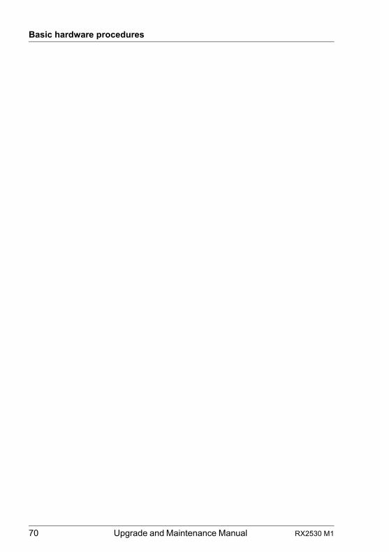
70 Upgrade and Maintenance Manual RX2530 M1
Basic hardware procedures
RX2530 M1 Upgrade and Maintenance Manual 71
5 Basic software procedures
5.1 Starting the maintenance task
5.1.1 Suspending BitLocker functionality
BitLocker Drive Encryption provides protection for operating system and data drives by encrypting the contents and requiring users to authenticate their credentials to access the information. In the scenario described here, BitLocker uses the compatible Trusted Platform Module (TPM) to detect if the computer's startup process has been modified from its original state.
I For additional information on how to use BitLocker on a computer without a compatible TPM, please refer to the "BitLocker Drive Encryption" documentation page at http://technet.microsoft.com/library/cc731549.aspx.
Suspending BitLocker Drive Encryption is a temporary method for removing BitLocker protection without decrypting the drive Windows is installed on. Suspend BitLocker before modifying the server’s hardware configuration or startup files. Resume BitLocker again after the maintenance procedure is complete.
V CAUTION!
– With BitLocker features enabled, modifying the system configuration (hardware or firmware settings) may render the system inaccessible. The system may enter Recovery Mode and require a 48-digits recovery password to return to normal operation.
Ensure to suspend BitLocker drive encryption before maintaining the server.
– When suspended, BitLocker uses a plain text key instead of the Trusted Platform Module (TPM) to read encrypted files. Keep in mind that information on this drive is not secure until BitLocker has been re-enabled.
Ê Ask the system administrator to suspend BitLocker-protection on the system volume, using the BitLocker Drive Encryption control panel item.
I This will temporarily disable BitLocker for maintenance purposes. The volume will not be decrypted and no keys will be discarded.
72 Upgrade and Maintenance Manual RX2530 M1
Basic software procedures
For Windows Server 2008:
Ê Open BitLocker Drive Encryption by clicking the Start button, clicking Control Panel, clicking Security, and then clicking BitLocker Drive Encryption.
Ê Select the system volume, and click Turn Off BitLocker.
Ê From the Turn Off BitLocker dialog box, click Disable BitLocker.
For Windows Server 2008 R2 and above:
Ê Open BitLocker Drive Encryption by clicking the Start button, clicking Control Panel, clicking System and Security, and then clicking BitLocker Drive Encryption.
Ê Select the system volume, and click Suspend Protection.
Ê Click Yes to confirm that your data will not be protected while BitLocker is suspended.
I In order to determine which features are accessible through the BitLocker setup wizard, it may be necessary to modify the BitLocker Group Policy settings.
For further information on how to suspend BitLocker drive encryption, please refer to the Microsoft TechNet library at http://technet.microsoft.com/library/cc731549.aspx.
Fujitsu service partners will find additional information (also available in Japanese) on the Fujitsu Extranet web pages.
5.1.2 Disabling SVOM boot watchdog functionality
The ServerView Operations Manager boot watchdog determines whether the server boots within a preset time frame. If the watchdog timer expires, the system will automatically reboot.
5.1.2.1 Viewing boot watchdog settings
Viewing boot watchdog settings in the BIOS
Ê Enter the BIOS.
Ê Select the Server Mgmt menu.
RX2530 M1 Upgrade and Maintenance Manual 73
Basic software procedures
Ê Under Boot Watchdog, you can obtain detailed information about the current watchdog status, time out intervals and actions that are triggered if watchdog time outs are exceeded.
I For detailed information on BIOS settings, refer to the corresponding BIOS Setup Utility reference manual.
Viewing boot watchdog settings in the iRMC web frontend
Ê Enter the ServerView iRMC web frontend.
Ê Select the Server Management menu.
Ê Under Watchdog Settings, you can obtain detailed information about the current watchdog status, time out intervals and actions that are triggered if watchdog time outs are exceeded.
I For detailed information on iRMC settings, refer to the "Integrated Remote Management Controller" user guide.
Viewing boot watchdog settings in ServerView Operations Manager
Ê In ServerView Operations Manager Single System View select Maintenance from the Information / Operation menu.
Ê Under ASR&R select the Watchdog tab to obtain detailed information about the current watchdog status, time out intervals and actions that are triggered if watchdog time outs are exceeded.
I For more detailed information, refer to the "ServerView Operations Manager - Server Management" user guide.
5.1.2.2 Configuring boot watchdog settings
If the system is to be started from removable boot media for firmware upgrade purposes, the Boot watchdog needs to be disabled before starting maintenance task. Otherwise, the Boot watchdog might initiate a system reboot before the flash process is complete.
V CAUTION!
An incomplete firmware upgrade process may render the server inaccessible or result in damaged / destroyed hardware.
Timer settings can be configured in the BIOS or using the ServerView iRMC web frontend.
74 Upgrade and Maintenance Manual RX2530 M1
Basic software procedures
Configuring boot watchdog settings in the BIOS
Ê Enter the BIOS.
Ê Select the Server Mgmt menu.
Ê Under Boot Watchdog set the Action setting to Continue.
Ê Save your changes and exit the BIOS.
I For detailed information on how to access the BIOS and modify settings, refer to the corresponding BIOS Setup Utility reference manual.
Configuring boot watchdog settings using the iRMC web frontend
Ê Enter the ServerView iRMC web frontend.
Ê Select the Server Management menu.
Ê Under Watchdog Settings select Continue from the Boot Watchdog drop down list.
Ê Click Apply for the changes to take effect.
I For detailed information on iRMC settings, refer to the "Integrated Remote Management Controller" user guide.
5.1.3 Removing backup and optical disk media
Ê Ask the system administrator to eject all remaining backup or optical media from the backup or optical disk drive before removing it from the server.
Ê If the backup media cannot be ejected by conventional means, and it is mandatory that the cartridge be removed prior to returning the drive for repair or disposing it, a manual tape extraction needs to be performed.
For further information on "forcible" tape ejection, please refer to the "Tape Facts" pages available to Fujitsu service partners from the following https address:
https://partners.ts.fujitsu.com/com/service/ps/Servers/PRIMERGY/Pages/TapeFacts.aspx
For the Japanese market, please contact Fujitsu support, if "forcible" tape ejection is necessary.
I Fujitsu does not assume responsibility for any damage to the tape drive, the data cartridge / tape or for the loss of any data resulting from manual tape extraction procedures.
RX2530 M1 Upgrade and Maintenance Manual 75
Basic software procedures
5.1.4 Verifying and configuring the backup software solution
I This task only applies to the Japanese market.
Depending on the backup software solution, it may be necessary to disable or delete the backup drive from the backup software drive list before starting the maintenance task.
This is the case for the following backup software solution:
– BackupExec
I Procedures may differ depending on the backup software. For details, refer to the dedicated documentation provided separately.
Further information on suitable backup software solutions and related documentation is available to Fujitsu service partners from the Fujitsu Extranet pages.
5.1.5 Note on server maintenance in a Multipath I/O environment
When booting your server offline from the ServerView Suite DVD to perform an offline BIOS / firmware update using the ServerView Update DVD or collect diagnostic data using PrimeCollect in a Multipath I/O environment, there is a risk of damaging the system configuration which may leave the system unable to boot.
I This is a known restriction of Windows PE with Multipath drivers.
Using Update Manager Express
Ê If performing an offline BIOS / firmware update, first of all prepare the ServerView Update DVD or USB stick:
Ê Download the latest ServerView Update DVD image from Fujitsu:
for the EMEA marketftp://ftp.ts.fujitsu.com/images/serverview
for the Japanese market: http://jp.fujitsu.com/platform/server/primergy/products/note/svsdvd/dvd/
76 Upgrade and Maintenance Manual RX2530 M1
Basic software procedures
Ê Burn the image to a DVD.
Ê In order to create a bootable USB stick, please proceed as described in the "Local System Update for PRIMERGY Servers" user guide.
Ê Before using the ServerView Update DVD or USB stick in an offline environment, properly shut down the server and disconnect all external I/O connections (like LAN, FC or SAS cables) from the system. Only keep mouse, keyboard, video cable and AC power cord connected.
I Ensure that all external I/O connections are uniquely identified so that you can reconnect them into their original locations after concluding the task.
To start Update Manager Express from the (physical) Update DVD or from a USB stick, proceed as follows:
Ê Prepare your Update DVD or USB stick as described in the "Local System Update for PRIMERGY Servers" user guide.
Ê Boot the server from the prepared Update DVD or USB stick:
DVD: Ê Switch on the server.
Ê Right after switching on the server, insert the Update DVD into the DVD drive and close the tray.
USB: Ê Connect the USB stick to the server.
Ê Switch on the server.
If the server does not boot from DVD or USB stick, proceed as follows:
Ê Reboot the server, e.g. by pressing the reset button on the front or switching the server off and then on again after a few seconds.
Ê Once the server has been started, press [F12] to enter the boot menu.
Ê Use the Ê and Ë cursor keys to select your DVD drive or USB stick as boot device and press [ENTER].
The server will now boot from the Update DVD or USB stick.
Ê After the boot process is complete, select your preferred GUI language.
The Update Manager Express main window will be displayed.
Ê Finish the intended maintenance task.
I For further information, refer to the "Local System Update for PRIMERGY Servers" user guide.
RX2530 M1 Upgrade and Maintenance Manual 77
Basic software procedures
Using PrimeCollect
To start PrimeCollect, proceed as follows:
Ê Before using PrimeCollect in an offline environment, properly shut down the server and disconnect all external I/O connections (like LAN, FC or SAS cables) from the system. Only keep mouse, keyboard, video cable and AC power cord connected.
I Ensure that all external I/O connections are uniquely identified so that you can reconnect them into their original locations after concluding the task.
Ê Switch on the server.
Ê Right after switching on the server, insert the ServerView Suite DVD into the DVD drive and close the drive tray.
If the server does not boot from DVD, proceed as follows:
Ê Reboot the server, e.g. by pressing the reset button on the front or switching the server off and then on again after a few seconds.
Ê Once the server has been started, press [F12] to enter the boot menu.
Ê Use the Ê and Ë cursor keys to select your DVD drive as boot device and press [ENTER].
The server will now boot from the ServerView Suite DVD.
Ê After the boot process is complete, select your preferred GUI language.
Ê In the initial Installation Manager startup window, choose PrimeCollect from the Installation Manager mode section.
Ê Click Continue to proceed.
Ê Finish the intended maintenance task.
I For further information, refer to the "PrimeCollect" user guide.
Concluding the procedure
Ê After the update or diagnostic procedure has been completed, shut down the server, reconnect all external I/O connections and bring the system back to normal operation.
Ê If necessary, perform this procedure for all remaining servers within the Multipath environment.
78 Upgrade and Maintenance Manual RX2530 M1
Basic software procedures
5.1.6 Switching on the ID indicator
When working in a datacenter environment, switch on the ID indicator on the front and rear connector panels of the server for easy identification.
I For further information, refer to section "Locating the defective server" on page 45 or to the "ServerView Suite Local Service Concept (LSC)" and "Integrated Remote Management Controller" user guides.
Using the ID button on the front panel
Ê Press the ID button on the front panel to switch on the system identification LEDs.
I For further information, refer to section "Indicators on the front panel" on page 365.
Using the iRMC web frontend
Ê Enter the ServerView iRMC web frontend.
Ê Under System Overview, click Identify LED On to switch on the ID indicators.
Using ServerView Operations Manager
Ê In ServerView Operations Manager Single System View press the Locate button in the title bar to switch on the ID indicators.
RX2530 M1 Upgrade and Maintenance Manual 79
Basic software procedures
5.2 Completing the maintenance task
5.2.1 Updating or recovering the system board BIOS and iRMC
I For the Japanese market, follow the instructions provided separately.
After replacing the system board, memory or a CPU, it is essential to upgrade the BIOS and iRMC to the latest version. The latest BIOS and iRMC versions are available from the Fujitsu support internet pages at:
http://ts.fujitsu.com/support/ (global market)http://jp.fujitsu.com/platform/server/primergy/downloads/ (Japanese market)
I Fujitsu does not assume responsibility for any damage done to the server or for the loss of any data resulting from BIOS updates.
5.2.1.1 Updating or recovering the system board BIOS
BIOS flash procedure
Ê Perform the BIOS flash procedure as described in your server’s "BIOS Setup Utility" reference manual.
BIOS recovery procedure
Ê Perform the BIOS recovery procedure as described in your server’s "BIOS Setup Utility" reference manual.
5.2.1.2 Updating or recovering the iRMC
iRMC flash procedure
Ê Prepare a USB stick including the bootable iRMC firmware update image.
Ê Connect the USB stick to the USB port.
I Ensure that only the USB device with the iRMC firmware is connected to the USB port. Remove all other USB devices temporarily.
Ê Restart the server.
Ê The system will detect the USB stick.
80 Upgrade and Maintenance Manual RX2530 M1
Basic software procedures
I If the BIOS cannot identify the USB stick, the pop-up message Failed to boot for Emergency flash. Please Reset now. will show up in the center of the screen.
Ê Choose one of the following options from the update tool menu to start the iRMC update process:
NormalChoose this option to update an existing system board.
Initial Choose this option if the system board has been replaced prior to the iRMC update procedure. This option will perform all relevant flash procedures in a row, including the iRMC firmware and bootloader.
V CAUTION!
Do not interrupt the iRMC upgrade process after it has started. If the process is interrupted, the iRMC BIOS may be permanently corrupted.
I If the iRMC does not work after flashing, disconnect the system from the mains and reconnect it again.
Ê After completion of the flash process, remove the USB stick and restart the server.
iRMC recovery procedure
Ê Prepare a USB stick including the bootable iRMC firmware update image.
Ê Ensure that the server has been shut down and disconnected from the mains as described in section "Disconnecting the server from the mains" on page 49.
Ê Connect the USB stick to the USB port.
I Ensure that only the USB device with the iRMC firmware is connected to the USB port. Remove all other USB devices temporarily.
Ê Connect the server to the mains while pushing the ID button on the front panel. Ask a second person to help you if necessary.
Ê Ensure that the Global Error indicator and the ID indicator are flashing to indicate that the server is entering the iRMC recovery state.
Ê Press the Power On / Off button. The system starts the POST process.
I In iRMC recovery mode, the “FUJITSU” logo does not show up.
RX2530 M1 Upgrade and Maintenance Manual 81
Basic software procedures
Ê The system will detect the USB stick.
I If the BIOS cannot identify the USB stick, the pop-up message Failed to boot for Emergency flash. Please Reset now. will show up in the center of the screen.
Ê Choose the Recovery_L option from the update tool menu to start the iRMC update process.
V CAUTION!
Do not interrupt the iRMC upgrade process after it has started. If the process is interrupted, the iRMC BIOS may be permanently corrupted.
I If the iRMC does not work after flashing, disconnect the system from the mains and reconnect it again.
Ê Shut down the server by pressing the power On / Off button.
Ê Disconnect the server from the mains to exit the iRMC recovery state.
5.2.2 Verifying system information backup / restore
To avoid the loss of non-default settings when replacing the system board, a backup copy of important system configuration data is automatically stored from the system board NVRAM to the Chassis ID EPROM. After replacing the system board the backup data is restored from the Chassis ID board to the new system board.
In order to verify whether the backup or restore process has been successful, check the System Event Log (SEL) using the ServerView Operations Manager (see also section "Viewing and clearing the System Event Log (SEL)" on page 92).
After replacing the system board
Ê Check the SEL log files as described in section "Viewing and clearing the System Event Log (SEL)" on page 92 to verify whether the backup data on the Chassis ID EPROM has been restored to the system board:
Chassis IDPROM: BMC FW Restore successful
82 Upgrade and Maintenance Manual RX2530 M1
Basic software procedures
After replacing the Chassis ID EPROM
Ê Check the SEL log files as described in section "Viewing and clearing the System Event Log (SEL)" on page 92 to verify whether a backup copy of the system board settings has been transferred to the Chassis ID EPROM:
Chassis IDPROM: BMC FW Backup successful
5.2.3 Updating RAID controller firmware
After replacing the RAID controller, it is essential to upgrade the firmware to the latest version. The latest RAID controller firmware version is available from the Fujitsu support web pages at:http://ts.fujitsu.com/support/ (global market)http://jp.fujitsu.com/platform/server/primergy/downloads/ (Japanese market)
I Fujitsu does not assume responsibility for any damage done to the server or for the loss of any data resulting from firmware updates.For the Japanese market, follow the instructions provided separately.
Using the ServerView Update Manager
For a detailed description on how to update the RAID controller firmware using the ServerView Update Manager or Update Manager Express (UME), please refer to the following manuals:
– ServerView Update Manager:"ServerView Update Management" user guide
– ServerView Update Manager Express:"Local System Update for PRIMERGY Servers" user guide
Using the flash tool
The latest firmware files are available as ASPs (Autonomous Support Packages) for Windows or as DOS tools from the Fujitsu support web pages at:http://ts.fujitsu.com/support/ (global market)http://jp.fujitsu.com/platform/server/primergy/downloads/ (Japanese market)
Ê Select Drivers & Downloads.
Ê From the Select Product drop down lists, choose your PRIMERGY server or enter its serial or ident number into the search field.
Ê Select your operating system and version.
RX2530 M1 Upgrade and Maintenance Manual 83
Basic software procedures
Ê Select the desired component type (e.g. SAS RAID).
Ê Select your controller from the device list to expand a compilation of available drivers and firmware.
Ê Select the desired file and click Download for further instructions.
5.2.4 Enabling Option ROM scan
In order to configure an expansion card that has been installed or replaced, the card’s Option ROM has to be enabled in the system board BIOS. The card’s firmware is called by the system BIOS upon reboot and can be entered and configured.
Option ROM can be enabled permanently (e.g. in case of a boot controller that may require frequent setup) or temporarily for one-time configuration. When permanently enabling a controllers’s Option ROM, keep in mind that only two Option ROMs can be activated in the system board BIOS at a time.
Ê Enter the BIOS.
Ê From the Advanced menu select Option ROM Configuration.
Ê Identify the desired PCI slot and set its Launch Slot # OpROM setting to Enabled.
Ê Save your changes and exit the BIOS.
I Up to two Option ROMs can be activated in the system board BIOS at a time.For detailed information on how to access the BIOS and modify settings, refer to corresponding BIOS Setup Utility reference manual.
When the enabled expansion card is initialized during the POST phase of the boot sequence, a key combination is displayed temporarily to enter the expansion card’s firmware.
Ê Press the displayed key combination.
Ê Modify the expansion card firmware options as desired.
Ê Save your changes and exit the firmware.
I The expansion card’s option ROM can now be disabled in the system board BIOS.Exception: If the expansion card controls a permanent boot device, the card’s Option ROM has to remain enabled.
84 Upgrade and Maintenance Manual RX2530 M1
Basic software procedures
5.2.5 Verifying and configuring the backup software solution
I This task only applies to the Japanese market.
Disabling backup drives
Depending on the backup software solution, it may be necessary to disable or delete the backup drive from the backup software drive list and reconfigure backup jobs after completing the maintenance task.
This is the case for the following backup software solutions:
– Netvault for Windows– ARCServe– BackupExec
I Procedures may differ depending on the backup software. For details, refer to the dedicated documentation provided separately.
Further information on suitable backup software solutions and related documentation is available to Fujitsu service partners from the Fujitsu Extranet pages.
Re-enabling backup drives
If a backup drive has been disabled or deleted from the backup software drive list as described in section 5.1.4 on page 75, it has to be re-enabled to complete the maintenance task.
Ê Re-enable backup drives and revise backup software settings and cronjobs.
I Detailed information on suitable backup software solutions and related documentation is available to Fujitsu service partners from the Fujitsu Extranet pages
5.2.6 Resetting the boot retry counter
The boot retry counter is decremented from its preset value every time the POST watchdog initiates a system reboot. When the value has reached ’0’, the system will shut down and power off.
RX2530 M1 Upgrade and Maintenance Manual 85
Basic software procedures
5.2.6.1 Viewing the boot retry counter
The current boot retry counter status is available in the BIOS:
Ê Enter the BIOS.
Ê Select the Server Mgmt menu.
Ê Under Boot Retry Counter the current number of remaining boot attempts is displayed. The value is further decremented with every failed boot attempt or system reboot resulting from critical system errors.
Ê Exit the BIOS.
5.2.6.2 Resetting the boot retry counter
The boot retry counter should be reset to its original value concluding every service task.
I Please note, if the customer does not know about the original boot retry values:
If the system boots up and no further errors occur within 6 hours after that successful boot attempt, the boot retry counter will automatically be reset to its default value. Please take into account, that the specified number of boot attempts can only be determined after this period of time.
If the customer knows about the original boot retry values, proceed as follows to reset or configure the boot retry counter:
Resetting the boot retry counter in the BIOS
Ê Enter the BIOS.
Ê Select the Server Mgmt menu.
Ê Under Boot Retry Counter press the [+] or [-]keys to specify the maximum number of boot attempts (0 to 7).
Ê Exit the BIOS.
Resetting the boot retry counter using the ServerView Operations Manager
Ê In the ServerView Operations Manager Administration view, select Server Configuration.
86 Upgrade and Maintenance Manual RX2530 M1
Basic software procedures
Ê If more than one server is managed in SVOM, select the target server and click Next.
Ê From the Server Configuration menu pane, choose Restart Options.
Ê Under Reboot Retries, specify the maximum number of boot attempts (0 to 7) in the Default for reboot tries field.
Resetting the boot retry counter using iRMC web frontend
Ê Enter the ServerView iRMC web frontend.
Ê Select the Server Management menu.
Ê The following boot retry counter settings are available under ASR&R Options:
Ê Under Retry counter max specify the maximum number of attempts to boot the operating system (0 to 7).
Ê Under Retry counter the current number of remaining boot attempts is displayed. Overwrite this value with the maximum number of boot attempts specified above in order to reset the boot retry counter.
Ê Click Apply for the changes to take effect.
I For detailed information on iRMC settings, refer to the "Integrated Remote Management Controller" user guide.
5.2.7 Resetting the error status after replacing memory modules or processors
5.2.7.1 Memory modules
ServerView Operations Manager may report a defective memory module in case of a memory error.
I Important note
After replacing a defective memory module, please check if the error counter has been reset automatically. If the memory slot is still marked as failed, please reset the error counter manually using one of the methods below.
Using the iRMC web frontend
Ê Enter the ServerView iRMC web frontend.
RX2530 M1 Upgrade and Maintenance Manual 87
Basic software procedures
Ê Select the System Information menu.
Ê Under System Components, select the check boxes next to the affected memory modules.
Ê From the drop down list, select Reset Error Counter.
Ê Click Apply for the changes to take effect.
Using ServerView Maintenance Tools (Windows only)
Ê Launch the ServerView Maintenance Tools:
– Windows Server 2008 R2 and below:Start > (All) Programs > Fujitsu > ServerView Suite > Agents > Maintenance Tools
– Windows Server 2012 and above:Start > Apps > Fujitsu > Maintenance Tools
Ê Choose the Memory status tab.
Ê Select the memory module which shows the pre-failure status.
Ê Click on Reset Status.
I The Reset Status button will only be available if the selected memory module contains errors.
Ê Ensure that all pre-fail / fail status issues have been resolved in ServerView Operations Manager.
Using the command line interface (Linux only)
The memory error counter can be reset using the meclear utility which is part of the ServerView agents for Linux.
I meclear (Memory Module Error Counter Reset Utility) allows to reset the error count collected for a memory module, for example after it has been replaced.For further details, please refer to the meclear manual pages.
Ê Log in as root.
Ê Enter the command below, followed by [ENTER]:/usr/sbin/meclear
Ê Select the number of a memory module with a status other than "OK" or "Not available".
88 Upgrade and Maintenance Manual RX2530 M1
Basic software procedures
Ê Repeat the step above until all memory modules show the "OK" status.
Ê Ensure that all pre-fail / fail status issues have been resolved in ServerView Operations Manager.
5.2.7.2 Processors
ServerView Operations Manager may report a defective processor in case of a critical error.
I Important note
After replacing a defective CPU, the error counter must be reset manually using one of the methods below.
Using ServerView Maintenance Tools (Windows only)
Ê Launch the ServerView Maintenance Tools:
– Windows Server 2008 R2 and below:Start > (All) Programs > Fujitsu > ServerView Suite > Agents > Maintenance Tools
– Windows Server 2012 and above:Start > Apps > Fujitsu > Maintenance Tools
Ê Choose the CPU status tab.
Ê Select the CPU which shows the pre-failure status.
Ê Click on Reset Status.
Ê Ensure that all pre-fail / fail status issues have been resolved in ServerView Operations Manager.
Using the command line (Linux only)
Proceed as follows to reset the error counter of a specific processor:
Ê Log in as root.
Ê Enter the command below, followed by [ENTER]:
– For rack and tower servers (RX and TX server series):/usr/sbin/eecdcp -c oc=0609 oi=<CPU#>
– For blade and scale-out servers (BX and CX server series):/usr/sbin/eecdcp -c oc=0609 oi=<CPU#> cab=<cabinet nr>
RX2530 M1 Upgrade and Maintenance Manual 89
Basic software procedures
To identify the cabinet number, enter the following command:/usr/sbin/eecdcp -c oc=E204
I <CPU#> parameters are "0" for CPU 1 and "1" for CPU 2.
Ê If the error status cannot be reset with the method above, please use the following procedure for resetting the error counter of all processors:
Ê Log in as root.
Ê Enter the commands below, followed by [ENTER]:
1. /etc/init.d/srvmagt stop/etc/init.d/srvmagt_scs stop/etc/init.d/eecd stop/etc/init.d/eecd_mods_src stop
2. cd /etc/srvmagt
3. rm -f cehist.bin
4. /etc/init.d/eecd_mods_src start/etc/init.d/eecd start/etc/init.d/srvmagt start/etc/init.d/srvmagt_scs start
Ê Ensure that all pre-fail / fail status issues have been resolved in ServerView Operations Manager.
5.2.8 Enabling SVOM boot watchdog functionality
If ServerView Operations Manager boot watchdog functionality has been disabled for firmware upgrade purposes (see section "Disabling SVOM boot watchdog functionality" on page 72), it has to be re-enabled to complete the maintenance task.
Timer settings can be configured in the BIOS or using the ServerView iRMC web frontend:
Configuring boot watchdog settings in the BIOS
Ê Enter the BIOS.
Ê Select the Server Mgmt menu.
Ê Under Boot Watchdog set the Action setting to Reset.
90 Upgrade and Maintenance Manual RX2530 M1
Basic software procedures
Ê Save your changes and exit the BIOS.
I For detailed information on how to access the BIOS and modify settings, refer to the corresponding BIOS Setup Utility reference manual.
Configuring boot watchdog settings using the iRMC web frontend
Ê Enter the ServerView iRMC web frontend.
Ê Select the Server Management menu.
Ê Under Watchdog Settings ensure that the check box next to Boot Watchdog is selected. From the drop down list choose Reset and specify the desired timeout delay.
Ê Click Apply for the changes to take effect.
I For detailed information on iRMC settings, refer to the "Integrated Remote Management Controller" user guide.
5.2.9 Enabling replaced components in the system BIOS
When a processor, an expansion card, or a memory module fails, the defective component will be set to Disabled or Failed in the system BIOS. The server will then reboot with only the intact hardware components remaining in the system configuration. After replacing the defective component, it needs to be re-enabled in the system board BIOS.
Ê Enter the BIOS.
Ê Select the Advanced menu.
Ê Select the status menu of the desired component:
– Processors: CPU Status
I This option is only available for multi-processor systems.
– Memory: Memory Status– Expansion cards: PCI Status
Ê Reset replaced components to Enable.
Ê Save your changes and exit the BIOS.
I For detailed information on how to access the BIOS and modify settings, refer to the corresponding BIOS Setup Utility reference manual.
RX2530 M1 Upgrade and Maintenance Manual 91
Basic software procedures
5.2.10 Verifying the memory mode
If a memory module fails, the server will reboot and the defective module will be disabled. As a result, the current operation mode (e.g. Mirrored Channel mode) may no longer be available due to a lack of identical memory module pairs. In this case, the operation mode will automatically revert to Independent Channel Mode.
I For detailed information on memory operation modes available for your server, refer to section "Modes of operation" on page 227.
After replacing the defective module(s) the memory operation mode is automatically reset to its original state. It is recommended to verify that the operation mode has been correctly.
Ê Enter the BIOS.
Ê Select the Advanced menu.
Ê Under Memory Status verify that none of the memory modules are marked as Failed.
Ê Save your changes (if applicable) and exit the BIOS.
I For detailed information on how to access the BIOS and modify settings, refer to the corresponding BIOS Setup Utility reference manual.
5.2.11 Verifying the system time settings
I This task only applies to Linux environments.
After the system board has been replaced, the system time is set automatically. By default, the RTC (Real Time Clock) time standard is set as the local time.
If a Linux OS is used and the hardware clock has been configured as UTC (Universal Time, Coordinated) in the operating system, the BMC local time may not be mapped correctly.
Ê After replacing the system board, ask the system administrator whether the RTC or UTC time standard is to be used as system time.
I If the system time (RTC) is set to UTC, the SEL (System Event Log) time stamps may differ from the local time.
Ê Enter the BIOS.
92 Upgrade and Maintenance Manual RX2530 M1
Basic software procedures
Ê Select the Main menu.
Ê Under System Time and System Date specify the correct time and date.
I By default, the system time set in the BIOS is RTC (Real Time Clock) local time. If your IT infrastructure relies on universally accepted time standards, set the System Time to UTC (Universal Time, Coordinated) instead. Greenwich Mean Time (GMT) can be considered equivalent to UTC.
Ê Save your changes and exit the BIOS.
I For detailed information on how to access the BIOS and modify settings, refer to the corresponding BIOS Setup Utility reference manual
5.2.12 Viewing and clearing the System Event Log (SEL)
5.2.12.1 Viewing the SEL
You can view the System Event Log (SEL) using the ServerView Operations Manager or the ServerView iRMC web frontend:
Viewing the SEL in ServerView Operations Manager
Ê In ServerView Operations Manager Single System View select Maintenance from the Information / Operation menu.
Ê Under Maintenance select System Event Log.
Ê Select the message type(s) you want to display:
– Critical events– Major events– Minor events– Informational events
I Note on the SVOM Driver Monitor
The Driver Monitor view gives you an overview of the monitored components as well as the associated events contained in the system event log on the managed server.
Under Monitored Components the monitored components are listed. If a component has the status Warning or Error, you can select it in the list and click Acknowledge. This confirms the event on the server side. You
RX2530 M1 Upgrade and Maintenance Manual 93
Basic software procedures
may have to log on to the server beforehand. The status of the component will then be reset to ok. To see the new status you must refresh the Driver Monitor view with Refresh.
I For detailed information on how to view and sort the SEL using ServerView Operations Manager, refer to the "ServerView Operations Manager - Server Management" user guide.
Viewing the SEL using the iRMC web frontend
Ê Enter the ServerView iRMC web frontend.
Ê Select the Event Log and choose the Internal Event Log submenu.
Ê Under Internal Event Log Content the SEL is being displayed. In order to filter the list, select the check boxes next to the desired event types and press Apply for the changes to take effect.
I For detailed information on iRMC settings, refer to the "Integrated Remote Management Controller" user guide.
5.2.12.2 Clearing the SEL
You can clear the System Event Log (SEL) using the ServerView iRMC web frontend:
Ê Enter the ServerView iRMC web frontend.
Ê Select the Event Log and choose the Internal Event Log submenu.
Ê Under Internal Event Log Information click Clear Internal Event Log to clear the SEL.
I For detailed information on iRMC settings, refer to the "Integrated Remote Management Controller" user guide.
5.2.13 Updating the NIC configuration file in a Linux environment
In order to prevent errors caused by changing network device names (eth<x>), it is recommended to store the MAC address (hardware address) of a network interface card in the related NIC configuration file of the Linux OS.When replacing a network controller or the system board with onboard LAN controllers in a server running Linux OS, the MAC address will change but not automatically be updated in the definition file.
94 Upgrade and Maintenance Manual RX2530 M1
Basic software procedures
In order to prevent communication problems, it is necessary to update the changed MAC address stored in the related ifcfg-eth<x> definition file.
To update the MAC address, proceed as follows:
I Procedures may differ depending on your Linux OS or the definition file on the client system. Use the following information as reference. Ask the system administrator to change the definition file.
Ê After replacing a network controller or the system board, switch on and boot the server as described in section "Switching on the server" on page 61.
kudzu, the hardware configuration tool for Red Hat Linux, will launch at boot and detect the new and / or changed hardware on your system.
I kudzu may not launch at boot depending on the client’s environment.
Ê Select Keep Configuration and Ignore to complete the boot process.
Ê Use the vi text editor to specify the MAC address in the HWADDR section of the ifcfg-eth<x> file:
I The MAC address can be found on the type label attached to the system board or network controller.
Example:
In order to modify the definition file for network controller 1, enter the following command:# vi /etc/sysconfig/network-scripts/ifcfg-eth1
In vi, specify the new MAC address as follows:HWADDR=xx:xx:xx:xx:xx:xx
Ê Save and close the definition file.
Ê For the changes to take effect, you need to reboot the network by entering the following command:# service network restart
I If the system board or network controller offers multiple LAN ports, it is necessary to update the remaining ifcfg-eth<x> definition files accordingly.
Ê Update the NIC configuration file to reflect the new card sequence and MAC address.
RX2530 M1 Upgrade and Maintenance Manual 95
Basic software procedures
5.2.14 Resuming BitLocker functionality
If BitLocker Drive Encryption has been suspended for maintenance purposes (see section "Suspending BitLocker functionality" on page 71), it has to be re-enabled to complete the service task.
I If BitLocker Drive Encryption has been suspended prior to replacing components you won't be asked for a recovery key when rebooting the server after the maintenance task. However, if BitLocker functionality has not been suspended, Windows will enter recovery mode and ask you to input recovery key for further booting.
Ê In this case, ask the system administrator to enter the recovery key in order to boot the operating system.
Ê Ask the system administrator to enable the previously suspended BitLocker-protection on the system volume, using the BitLocker Drive Encryption control panel item:
For Windows Server 2008:
Ê Open BitLocker Drive Encryption by clicking the Start button, clicking Control Panel, clicking Security, and then clicking BitLocker Drive Encryption.
Ê Select the system volume, and click Turn On BitLocker.
For Windows Server 2008 R2 and above:
Ê Open BitLocker Drive Encryption by clicking the Start button, clicking Control Panel, clicking System and Security, and then clicking BitLocker Drive Encryption.
Ê Select the system volume, and click Resume Protection.
I For further information on how to resume BitLocker drive encryption, please refer to the Microsoft TechNet library at http://technet.microsoft.com/library/cc731549.aspx.
Fujitsu service partners will find additional information (also available in Japanese) on the Fujitsu Extranet web pages.
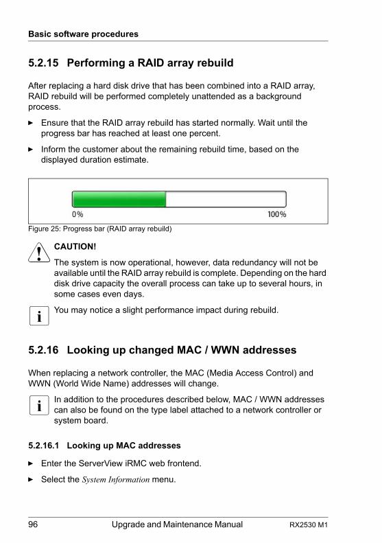
96 Upgrade and Maintenance Manual RX2530 M1
Basic software procedures
5.2.15 Performing a RAID array rebuild
After replacing a hard disk drive that has been combined into a RAID array, RAID rebuild will be performed completely unattended as a background process.
Ê Ensure that the RAID array rebuild has started normally. Wait until the progress bar has reached at least one percent.
Ê Inform the customer about the remaining rebuild time, based on the displayed duration estimate.
Figure 25: Progress bar (RAID array rebuild)
V CAUTION!
The system is now operational, however, data redundancy will not be available until the RAID array rebuild is complete. Depending on the hard disk drive capacity the overall process can take up to several hours, in some cases even days.
I You may notice a slight performance impact during rebuild.
5.2.16 Looking up changed MAC / WWN addresses
When replacing a network controller, the MAC (Media Access Control) and WWN (World Wide Name) addresses will change.
I In addition to the procedures described below, MAC / WWN addresses can also be found on the type label attached to a network controller or system board.
5.2.16.1 Looking up MAC addresses
Ê Enter the ServerView iRMC web frontend.
Ê Select the System Information menu.
RX2530 M1 Upgrade and Maintenance Manual 97
Basic software procedures
Ê Under Network Inventory, you will find detailed information on each network controller in the managed PRIMERGY server, including its MAC address.
I This information is only available with the iRMC S4 or above.Only network controllers supporting the Command Line Protocol (CLP) will be displayed.
Ê Inform the customer about the changed MAC address.
5.2.16.2 Looking up WWN addresses
Emulex FC / FCoE adapters
Ê Enable the network controller’s Option ROM in the system board BIOS as described in section "Enabling Option ROM scan" on page 83.
Ê Restart the server.
Ê During boot, as soon as the Emulex BIOS utility option appears, press [ALT]+[E] or [CTRL]+[E].
Ê Under Emulex Adapters in the System you will find all available Emulex adapters and their WWN addresses.
Ê Note down the new 16-digit WWN address.
Ê Press [Esc] to exit the Emulex BIOS utility.
Ê Inform the customer about the changed WWN address.
QLogic FC adapters
Ê Enable the network controller’s Option ROM in the system board BIOS as described in section "Enabling Option ROM scan" on page 83.
Ê Restart the server.
Ê During boot, as soon as the QLogic BIOS utility option appears, press [ALT]+[Q] or [CTRL]+[Q].
Ê Under Select Host Adapter use the arrow keys æ/Ë to select the desired FC / FCoE adapter and press [Enter].
Ê From the Fast!UTIL Options menu, select Configuration Settings, and press [Enter].
Ê From the Configuration Settings menu, select Adapter Settings, and press [Enter].
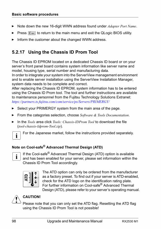
98 Upgrade and Maintenance Manual RX2530 M1
Basic software procedures
Ê Note down the new 16-digit WWN address found under Adapter Port Name.
Ê Press [Esc] to return to the main menu and exit the QLogic BIOS utility.
Ê Inform the customer about the changed WWN address.
5.2.17 Using the Chassis ID Prom Tool
The Chassis ID EPROM located on a dedicated Chassis ID board or on your server’s front panel board contains system information like server name and model, housing type, serial number and manufacturing data.In order to integrate your system into the ServerView management environment and to enable server installation using the ServerView Installation Manager, system data needs to be complete and correct.After replacing the Chassis ID EPROM, system information has to be entered using the Chassis ID Prom tool. The tool and further instructions are available to maintenance personnel from the Fujitsu Technology Solutions Extranet:https://partners.ts.fujitsu.com/com/service/ps/Servers/PRIMERGY/
Ê Select your PRIMERGY system from the main area of the page.
Ê From the categories selection, choose Software & Tools Documentation.
Ê In the Tools area click Tools: Chassis-IDProm Tool to download the file (tool-chassis-Idprom-Tool.zip).
I For the Japanese market, follow the instructions provided separately.
Note on Cool-safe® Advanced Thermal Design (ATD)
I If the Cool-safe® Advanced Thermal Design (ATD) option is available and has been enabled for your server, please set information within the Chassis ID Prom Tool accordingly.
V CAUTION!
Please note that you can only set the ATD flag. Resetting the ATD flag using the Chassis ID Prom Tool is not possible!
The ATD option can only be ordered from the manufacturer as a factory preset. To find out if your server is ATD-enabled, check for the ATD logo on the identification rating plate.For further information on Cool-safe® Advanced Thermal Design (ATD), please refer to your server’s operating manual.
RX2530 M1 Upgrade and Maintenance Manual 99
Basic software procedures
5.2.18 Configuring LAN teaming
Use ServerView Operations Manager to obtain detailed information on existing LAN teams:
Ê In ServerView Operations Manager Single System View select System Status from the Information / Operation menu.
Ê Under Network Interfaces select LAN Teaming.
Ê The Network Interfaces (Summary) overview shows all configured LAN teams and their components. Choose a LAN team to display further details:
– LAN Team Properties: Properties of the selected LAN team– LAN Team Statistics: Available statistics about the selected LAN team
I For more detailed information, refer to the "ServerView Operations Manager - Server Management" user guide.
5.2.18.1 After replacing / upgrading LAN controllers
Please note when re-using a replaced LAN controller:
Ê Confirm with the customer whether the LAN controller you have replaced has been used as part of a LAN teaming configuration.
Ê If LAN teaming has been active, you will need to restore the configuration using the LAN driver utility after replacing the LAN controller.Ensure that the controllers have been assigned as primary or secondary according to your requirements.
I For details, refer to the relevant LAN driver manual.
5.2.18.2 After replacing the system board
Ê Confirm with the customer whether the onboard LAN controller you have replaced has been used as part of a LAN teaming configuration.
Ê If LAN teaming has been active, you will need to restore the configuration using the LAN driver utility after replacing the system board.
I For details, refer to the relevant LAN driver manual.
100 Upgrade and Maintenance Manual RX2530 M1
Basic software procedures
5.2.19 Switching off the ID indicator
Press the ID button on the front panel, or use the iRMC web frontend or ServerView Operations Manager to switch off the ID indicator after the maintenance task has been concluded successfully.
I For further information, refer to section "Locating the defective server" on page 45 or to the "ServerView Suite Local Service Concept (LSC)" and "Integrated Remote Management Controller" user guides.
Using the ID button on the front panel
Ê Press the ID button on the front panel to switch off the ID indicators.
Using the iRMC web frontend
Ê Enter the ServerView iRMC web frontend.
Ê Under System Overview, click Identify LED Off to switch off the ID indicators.
Using ServerView Operations Manager
Ê In ServerView Operations Manager Single System View and press the Locate button in the title bar to switch off the ID indicator.
5.2.20 Performing a fan test after replacing a defective fan
After replacing a defective system fan or power supply unit containing a defective fan, the fan error indicators will stay lit until the next fan test. By default, a fan test is automatically started every 24 hours. The first automatic fan test being performed after replacing a fan will turn off the fan error indicator.If you want to start the fan test manually, you can do so by following the description below:
Executing the fan test via the iRMC Web interface
Ê Log into the iRMC web interface.
Ê Under Sensors select Fans.
Ê Select the replaced fan in the system fans group and click Start Fan Test.
I For detailed information on iRMC settings, refer to the "Integrated Remote Management Controller" user guide.
RX2530 M1 Upgrade and Maintenance Manual 101
Basic software procedures
Executing the fan test via ServerView Operations Manager
Ê Open the ServerView Operations Manager and log in.
Ê Under Administration select Server Configuration.
Ê In the hierarchy tree of the Server list tab, select the server to be configured.
Ê In the right-hand side of the window, specify the details on the selected server and confirm your entries by clicking GO....In the left-hand section of the window, the Configuration tab is being activated.
Ê In the navigation area of the Configuration tab, select Other Settings.
Ê Under Daily Fan Test, set the daily fan test time to a few minutes from the current time. (Ensure to note down your previous setting.)
Ê Click Save Page.The fan test will be started at the specified time.
Ê After the fan test is complete, restore the time setting to its initial value and click Save Page.
I For more detailed information, refer to the "ServerView Operations Manager" user guide.
For the Japanese market: Executing the fan test via Chassis ID Prom Tool
I Please follow the instructions provided separately.
102 Upgrade and Maintenance Manual RX2530 M1
Basic software procedures

RX2530 M1 Upgrade and Maintenance Manual 103
6 Power supply
Safety notes
V CAUTION!
● Do not disassemble the power supply unit. Doing so may cause electric shock.
● Areas around the power supply unit may remain extremely hot after shutdown. After shutting down the server, wait for hot components to cool down before removing the power supply unit.
● When installing the power supply unit, be sure to confirm that the connector of the power supply unit is not damaged or bent.
● Do not insert your hands in the power supply unit slot when removing the power supply unit. Doing so may cause electric shock.
● If the power supply unit is hard to remove, do not pull out it by force.
● The power supply unit is heavy, so handle it carefully. If you drop it by mistake, injuries may result.
● For further safety information, please refer to chapter "Important information" on page 33.
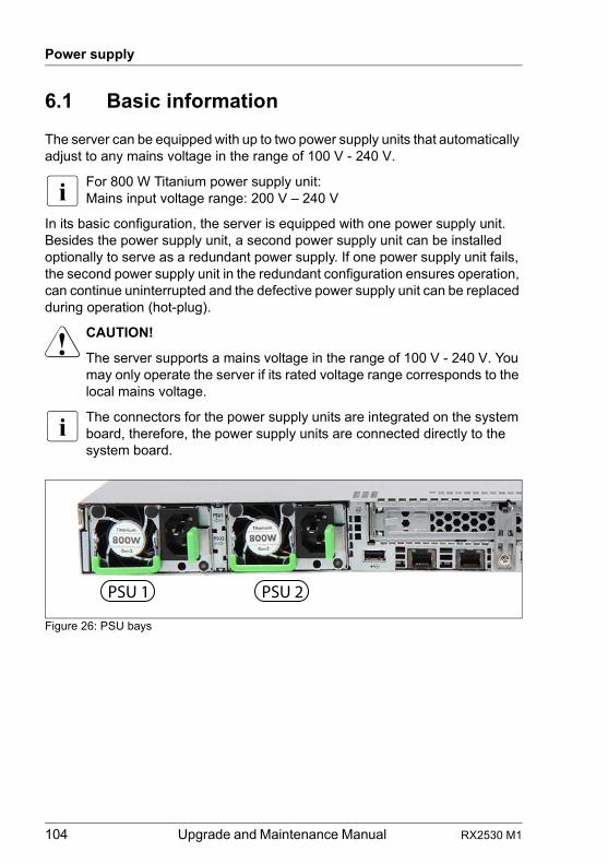
104 Upgrade and Maintenance Manual RX2530 M1
Power supply
6.1 Basic information
The server can be equipped with up to two power supply units that automatically adjust to any mains voltage in the range of 100 V - 240 V.
I For 800 W Titanium power supply unit:Mains input voltage range: 200 V – 240 V
In its basic configuration, the server is equipped with one power supply unit. Besides the power supply unit, a second power supply unit can be installed optionally to serve as a redundant power supply. If one power supply unit fails, the second power supply unit in the redundant configuration ensures operation, can continue uninterrupted and the defective power supply unit can be replaced during operation (hot-plug).
V CAUTION!
The server supports a mains voltage in the range of 100 V - 240 V. You may only operate the server if its rated voltage range corresponds to the local mains voltage.
I The connectors for the power supply units are integrated on the system board, therefore, the power supply units are connected directly to the system board.
Figure 26: PSU bays
PSU 1 PSU 2
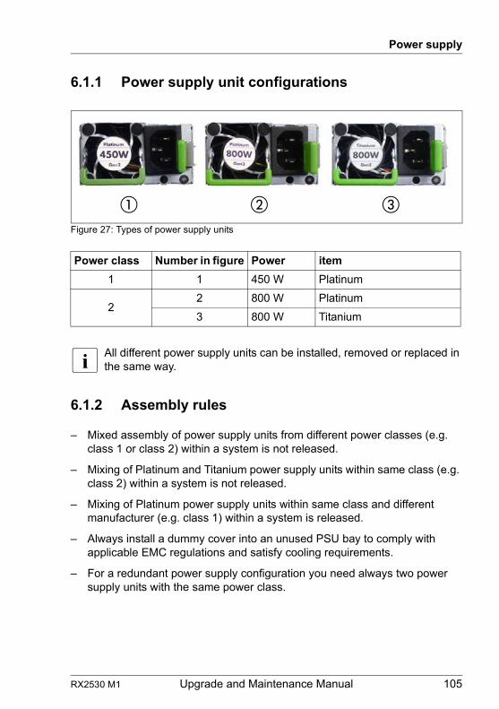
RX2530 M1 Upgrade and Maintenance Manual 105
Power supply
6.1.1 Power supply unit configurations
Figure 27: Types of power supply units
I All different power supply units can be installed, removed or replaced in the same way.
6.1.2 Assembly rules
– Mixed assembly of power supply units from different power classes (e.g. class 1 or class 2) within a system is not released.
– Mixing of Platinum and Titanium power supply units within same class (e.g. class 2) within a system is not released.
– Mixing of Platinum power supply units within same class and different manufacturer (e.g. class 1) within a system is released.
– Always install a dummy cover into an unused PSU bay to comply with applicable EMC regulations and satisfy cooling requirements.
– For a redundant power supply configuration you need always two power supply units with the same power class.
Power class Number in figure Power item
1 1 450 W Platinum
22 800 W Platinum
3 800 W Titanium
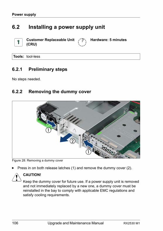
106 Upgrade and Maintenance Manual RX2530 M1
Power supply
6.2 Installing a power supply unit
6.2.1 Preliminary steps
No steps needed.
6.2.2 Removing the dummy cover
Figure 28: Removing a dummy cover
Ê Press in on both release latches (1) and remove the dummy cover (2).
V CAUTION!
Keep the dummy cover for future use. If a power supply unit is removed and not immediately replaced by a new one, a dummy cover must be reinstalled in the bay to comply with applicable EMC regulations and satisfy cooling requirements.
Customer Replaceable Unit(CRU)
Hardware: 5 minutes
Tools: tool-less
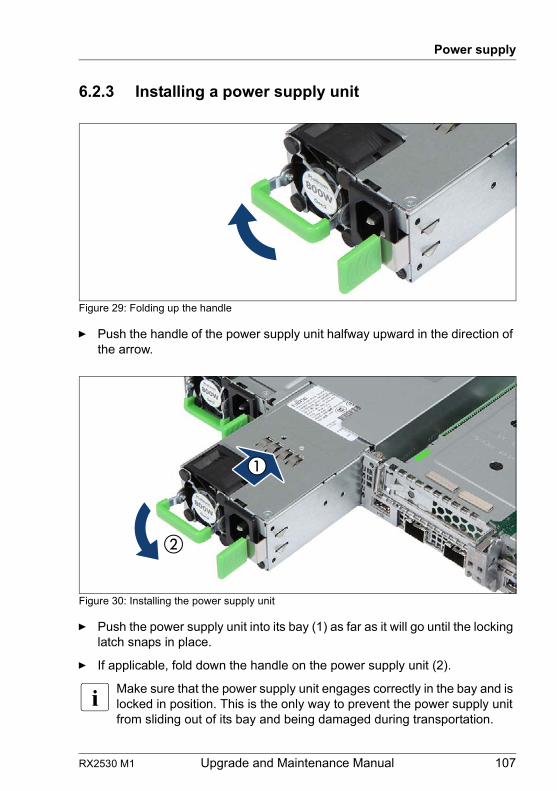
RX2530 M1 Upgrade and Maintenance Manual 107
Power supply
6.2.3 Installing a power supply unit
Figure 29: Folding up the handle
Ê Push the handle of the power supply unit halfway upward in the direction of the arrow.
Figure 30: Installing the power supply unit
Ê Push the power supply unit into its bay (1) as far as it will go until the locking latch snaps in place.
Ê If applicable, fold down the handle on the power supply unit (2).
I Make sure that the power supply unit engages correctly in the bay and is locked in position. This is the only way to prevent the power supply unit from sliding out of its bay and being damaged during transportation.
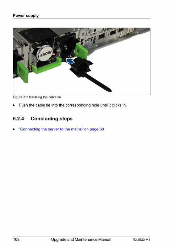
108 Upgrade and Maintenance Manual RX2530 M1
Power supply
Figure 31: Installing the cable tie
Ê Push the cable tie into the corresponding hole until it clicks in.
6.2.4 Concluding steps
Ê "Connecting the server to the mains" on page 60
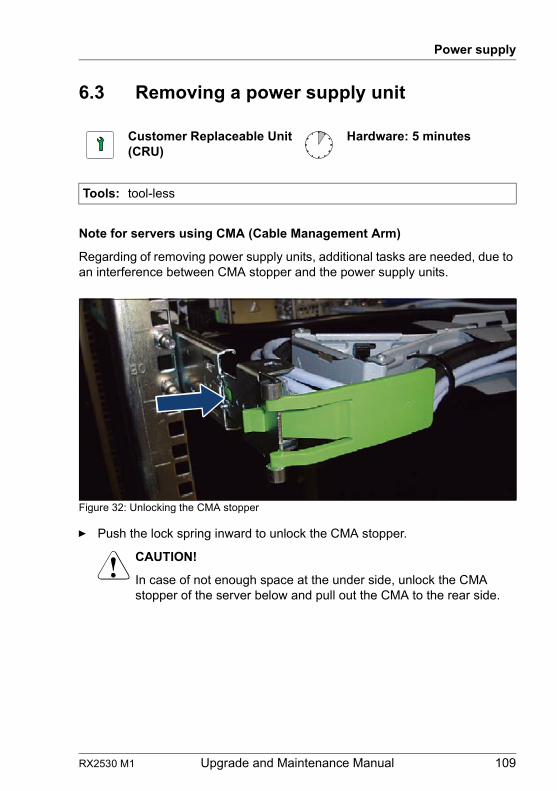
RX2530 M1 Upgrade and Maintenance Manual 109
Power supply
6.3 Removing a power supply unit
Note for servers using CMA (Cable Management Arm)
Regarding of removing power supply units, additional tasks are needed, due to an interference between CMA stopper and the power supply units.
Figure 32: Unlocking the CMA stopper
Ê Push the lock spring inward to unlock the CMA stopper.
V CAUTION!
In case of not enough space at the under side, unlock the CMA stopper of the server below and pull out the CMA to the rear side.
Customer Replaceable Unit(CRU)
Hardware: 5 minutes
Tools: tool-less
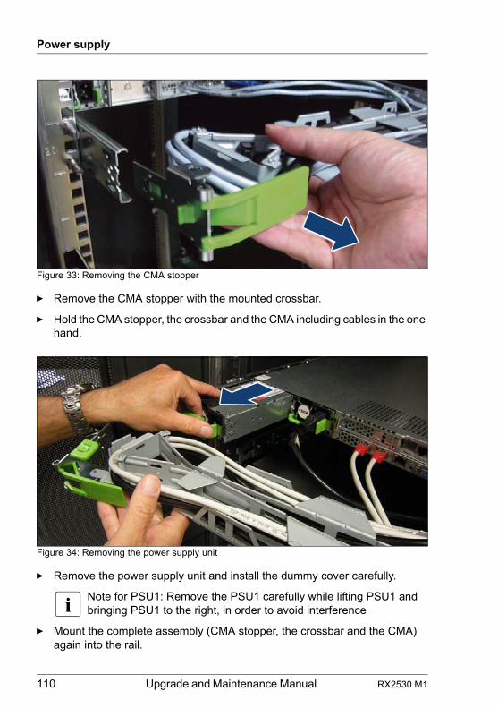
110 Upgrade and Maintenance Manual RX2530 M1
Power supply
Figure 33: Removing the CMA stopper
Ê Remove the CMA stopper with the mounted crossbar.
Ê Hold the CMA stopper, the crossbar and the CMA including cables in the one hand.
Figure 34: Removing the power supply unit
Ê Remove the power supply unit and install the dummy cover carefully.
I Note for PSU1: Remove the PSU1 carefully while lifting PSU1 and bringing PSU1 to the right, in order to avoid interference
Ê Mount the complete assembly (CMA stopper, the crossbar and the CMA) again into the rail.
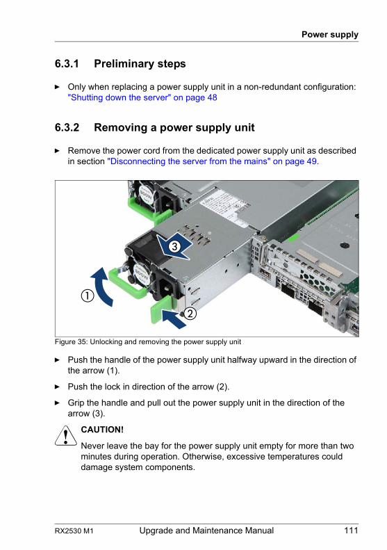
RX2530 M1 Upgrade and Maintenance Manual 111
Power supply
6.3.1 Preliminary steps
Ê Only when replacing a power supply unit in a non-redundant configuration: "Shutting down the server" on page 48
6.3.2 Removing a power supply unit
Ê Remove the power cord from the dedicated power supply unit as described in section "Disconnecting the server from the mains" on page 49.
Figure 35: Unlocking and removing the power supply unit
Ê Push the handle of the power supply unit halfway upward in the direction of the arrow (1).
Ê Push the lock in direction of the arrow (2).
Ê Grip the handle and pull out the power supply unit in the direction of the arrow (3).
V CAUTION!
Never leave the bay for the power supply unit empty for more than two minutes during operation. Otherwise, excessive temperatures could damage system components.
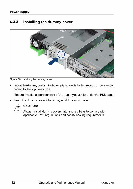
112 Upgrade and Maintenance Manual RX2530 M1
Power supply
6.3.3 Installing the dummy cover
Figure 36: Installing the dummy cover
Ê Insert the dummy cover into the empty bay with the impressed arrow symbol facing to the top (see circle).
Ensure that the upper rear cant of the dummy cover fits under the PSU cage.
Ê Push the dummy cover into its bay until it locks in place.
V CAUTION!
Always install dummy covers into unused bays to comply with applicable EMC regulations and satisfy cooling requirements.
RX2530 M1 Upgrade and Maintenance Manual 113
Power supply
6.4 Replacing a power supply unit
V CAUTION!
● When replacing a power supply unit in a non-redundant PSU configuration, the server must be switched off first.
● Replace the power supply unit after specifying the one that breaks down at work by revitalization.
Note for servers using CMA (Cable Management Arm)
Regarding of replacing power supply units, additional tasks are needed, due to an interference between CMA stopper and the power supply units.
Ê Push the lock spring inward to unlock the CMA stopper (see figure 32).
V CAUTION!
In case of not enough space at the under side, unlock the CMA stopper of the server below and pull out the CMA to the rear side
Ê Remove the CMA stopper with the mounted crossbar (see figure 33).
Ê Hold the CMA stopper, the crossbar and the CMA including cables in the one hand.
Ê Remove the power supply unit (see figure 34) and install the new power supply unit carefully.
I Note for PSU1: Remove the PSU1 carefully while lifting PSU1 and bringing PSU1 to the right, in order to avoid interference
Ê Mount the complete assembly (CMA stopper, the crossbar and the CMA) again into the rail.
Customer Replaceable Unit(CRU)
Hardware: 5 minutes
Tools: tool-less
114 Upgrade and Maintenance Manual RX2530 M1
Power supply
6.4.1 Preliminary steps
Ê "Locating the defective server" on page 45
Ê "Locating the defective component" on page 47
Ê Check which power supply unit is defective.
A power supply unit is defective when the indicator (1) in figure 268 lights orange. For more information see section "Connectors and indicators" on page 358.
Ê Only when replacing a power supply unit in a non-redundant configuration: "Shutting down the server" on page 48
Ê Remove the power cord from the defective power supply unit as described in section "Disconnecting the server from the mains" on page 49
6.4.2 Removing the defective power supply unit
Ê Remove the power supply unit as described in section "Removing a power supply unit" on page 111.
6.4.3 Installing the new power supply unit
Ê Install the power supply unit as described in section "Installing a power supply unit" on page 107.
6.4.4 Concluding steps
Ê Connect the power cord to the new power supply unit and secure it with a cable tie as described in section "Connecting the server to the mains" on page 60.
Ê Only when replacing a power supply unit in a non-redundant configuration: "Switching on the server" on page 61
Ê "Performing a fan test after replacing a defective fan" on page 100
RX2530 M1 Upgrade and Maintenance Manual 115
7 Hard disk drives / solid state drives
Safety notes
V CAUTION!
● The hard disk drive or solid state drive must not be removed from the installation frame by anyone except a service technician.
● The HDD/SSD modules (drives) must all be marked clearly so that they can be reinstalled into their original mounting locations after replacement. Otherwise, data may be lost.
● Do not touch the circuitry on boards or soldered parts. Hold the metallic areas or the edges of the circuit boards.
● Before removing a hard disk drive, wait for about 30 seconds until the disk has stopped spinning completely.
● When a hard disk drive is starting up, a resonant noise may be audible for a short while. This does not indicate a failure.
● Depending on the OS, you can configure the write cache settings for the hard disk drives. If a power failure should occur while the write cache is enabled, cached data may be lost.
● When disposing of, transferring, or returning a hard disk drive or solid state drive, wipe out the data on the drive for your own security.
● Rough handling of hard disk drives may damage the stored data. To cope with any unexpected problems, always back up important data. When backing up data to another hard disk drive, you should make backups on a file or partition basis.
● Be careful not to hit the hard disk drive or bring it into contact with metallic objects.
● Handle the device on a shock and vibration free surface.
● Do not use the device in extremely hot or cold locations, or locations with extreme temperature changes.
● Never attempt to disassemble the hard disk drive or solid state drive.
● For further safety information, please refer to chapter "Important information" on page 33.
116 Upgrade and Maintenance Manual RX2530 M1
Hard disk drives / solid state drives
7.1 Basic information
The hard disk drives or solid state drives which can be ordered for your server are supplied already mounted in an installation frame so that defective drives can be replaced and new drives can be added during operation. The hard disk drive or solid state drive and the installation frame together make up the HDD module or SSD module.
The server is shipped with one of the following HDD or SSD subsystems:
– 3.5-inch HDD subsystem:
Up to four 3.5-inch SAS/SATA HDD modules can be installed. Each HDD module can accommodate an SAS/SATA hard disk drive with a maximum height of 1 inch. The HDD module is connected to the HDD backplane wirelessly. This allows HDD modules to be plugged in or pulled out easily.
Hybrid configurations of SAS and SATA HDD modules are not supported.
– 2.5-inch HDD/SSD subsystem:
Up to four (one HDD backplane), eight (two HDD backplanes) or ten (one HDD backplane) 2.5-inch SAS/SATA HDD/SSD modules can be installed.
Each HDD/SSD module can accommodate a SAS/SATA hard disk drive or SATA solid state drive with a 2.5-inch format. The HDD/SSD modules are connected to the HDD backplane wirelessly. This allows HDD/SSD modules to be plugged in or pulled out easily. If the server has a corresponding RAID configuration, defective HDD/SSD modules can also be replaced during operation.
Hybrid configurations of SAS and SATA SSD / BC-SAS and BC-SATA HDD modules are not supported.
I In the configuration with up to 10 HDD/SSD modules, the first four HDD bays can be equipped with PCIe-SSDs, if a PCIe switch has been installed.
I For information on RAID controllers controlling the HDD/SSD modules see chapter "Expansion cards and backup units" on page 161.
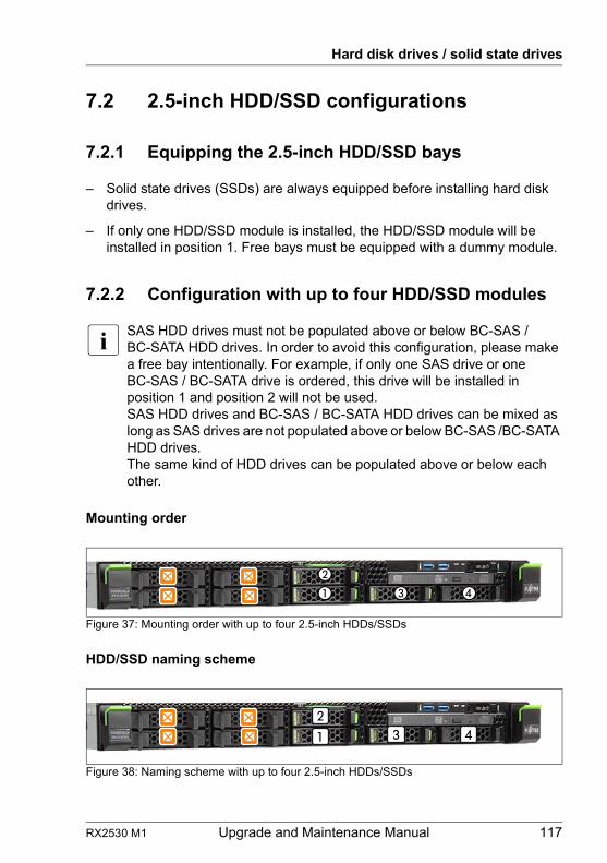
RX2530 M1 Upgrade and Maintenance Manual 117
Hard disk drives / solid state drives
7.2 2.5-inch HDD/SSD configurations
7.2.1 Equipping the 2.5-inch HDD/SSD bays
– Solid state drives (SSDs) are always equipped before installing hard disk drives.
– If only one HDD/SSD module is installed, the HDD/SSD module will be installed in position 1. Free bays must be equipped with a dummy module.
7.2.2 Configuration with up to four HDD/SSD modules
I SAS HDD drives must not be populated above or below BC-SAS / BC-SATA HDD drives. In order to avoid this configuration, please make a free bay intentionally. For example, if only one SAS drive or one BC-SAS / BC-SATA drive is ordered, this drive will be installed in position 1 and position 2 will not be used.SAS HDD drives and BC-SAS / BC-SATA HDD drives can be mixed as long as SAS drives are not populated above or below BC-SAS /BC-SATA HDD drives.The same kind of HDD drives can be populated above or below each other.
Mounting order
Figure 37: Mounting order with up to four 2.5-inch HDDs/SSDs
HDD/SSD naming scheme
Figure 38: Naming scheme with up to four 2.5-inch HDDs/SSDs
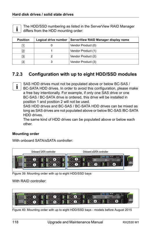
118 Upgrade and Maintenance Manual RX2530 M1
Hard disk drives / solid state drives
I The HDD/SSD numbering as listed in the ServerView RAID Manager differs from the HDD mounting order:
7.2.3 Configuration with up to eight HDD/SSD modules
I SAS HDD drives must not be populated above or below BC-SAS / BC-SATA HDD drives. In order to avoid this configuration, please make a free bay intentionally. For example, if only one SAS drive or one BC-SAS / BC-SATA drive is ordered, this drive will be installed in position 1 and position 2 will not be used.SAS HDD drives and BC-SAS / BC-SATA HDD drives can be mixed as long as SAS drives are not populated above or below BC-SAS /BC-SATA HDD drives.The same kind of HDD drives can be populated above or below each other.
Mounting order
With onboard SATA/sSATA controller:
Figure 39: Mounting order with up to eight HDD/SSD bays
With RAID controller:
Figure 40: Mounting order with up to eight HDD/SSD bays - models before August 2015
Position Logical drive number ServerView RAID Manager display name
[1] 0 Vendor Product (0)
[2] 1 Vendor Product (1)
[3] 2 Vendor Product (2)
[4] 3 Vendor Product (3)
Onboard SATA controller Onboard sSATA controller
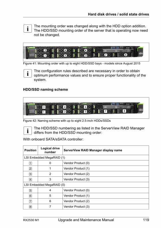
RX2530 M1 Upgrade and Maintenance Manual 119
Hard disk drives / solid state drives
I The mounting order was changed along with the HDD option addition. The HDD/SSD mounting order of the server that is operating now need not be changed.
Figure 41: Mounting order with up to eight HDD/SSD bays - models since August 2015
I The configuration rules described are necessary in order to obtain optimum performance values and to ensure proper functionality of the system.
HDD/SSD naming scheme
Figure 42: Naming scheme with up to eight 2.5-inch HDDs/SSDs
I The HDD/SSD numbering as listed in the ServerView RAID Manager differs from the HDD/SSD mounting order:
With onboard SATA/sSATA controller:
PositionLogical drive
numberServerView RAID Manager display name
LSI Embedded MegaRAID (1)
[1] 0 Vendor Product (0)
[2] 1 Vendor Product (1)
[3] 2 Vendor Product (2)
[4] 3 Vendor Product (3)
LSI Embedded MegaRAID (0)
[5] 4 Vendor Product (0)
[6] 5 Vendor Product (1)
[7] 6 Vendor Product (2)
[8] 7 Vendor Product (3)
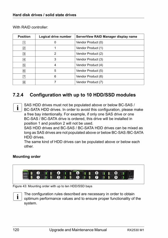
120 Upgrade and Maintenance Manual RX2530 M1
Hard disk drives / solid state drives
With RAID controller:
7.2.4 Configuration with up to 10 HDD/SSD modules
I SAS HDD drives must not be populated above or below BC-SAS / BC-SATA HDD drives. In order to avoid this configuration, please make a free bay intentionally. For example, if only one SAS drive or one BC-SAS / BC-SATA drive is ordered, this drive will be installed in position 1 and position 2 will not be used.SAS HDD drives and BC-SAS / BC-SATA HDD drives can be mixed as long as SAS drives are not populated above or below BC-SAS /BC-SATA HDD drives.The same kind of HDD drives can be populated above or below each other.
Mounting order
Figure 43: Mounting order with up to ten HDD/SSD bays
I The configuration rules described are necessary in order to obtain optimum performance values and to ensure proper functionality of the system.
Position Logical drive number ServerView RAID Manager display name
[1] 0 Vendor Product (0)
[2] 1 Vendor Product (1)
[3] 2 Vendor Product (2)
[4] 3 Vendor Product (3)
[5] 4 Vendor Product (4)
[6] 5 Vendor Product (5)
[7] 6 Vendor Product (6)
[8] 7 Vendor Product (7)
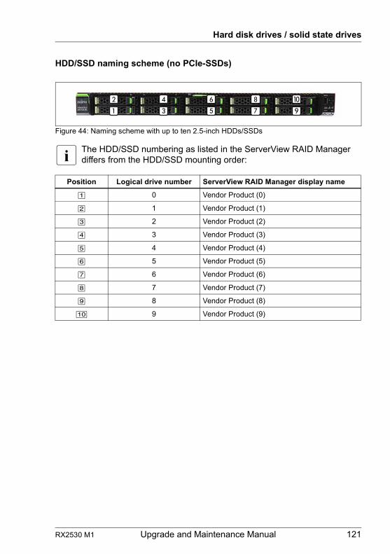
RX2530 M1 Upgrade and Maintenance Manual 121
Hard disk drives / solid state drives
HDD/SSD naming scheme (no PCIe-SSDs)
Figure 44: Naming scheme with up to ten 2.5-inch HDDs/SSDs
I The HDD/SSD numbering as listed in the ServerView RAID Manager differs from the HDD/SSD mounting order:
Position Logical drive number ServerView RAID Manager display name
[1] 0 Vendor Product (0)
[2] 1 Vendor Product (1)
[3] 2 Vendor Product (2)
[4] 3 Vendor Product (3)
[5] 4 Vendor Product (4)
[6] 5 Vendor Product (5)
[7] 6 Vendor Product (6)
[8] 7 Vendor Product (7)
[9] 8 Vendor Product (8)
[10] 9 Vendor Product (9)
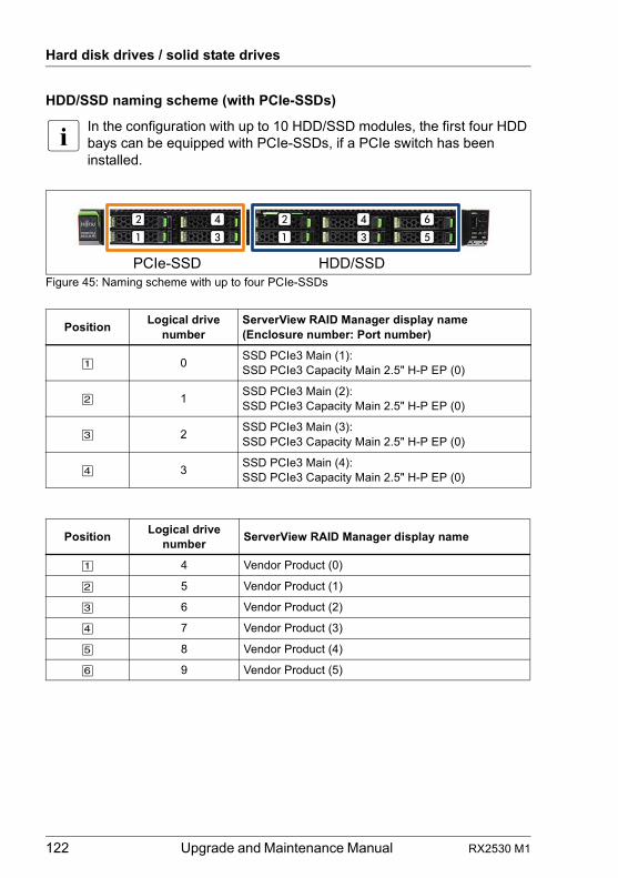
122 Upgrade and Maintenance Manual RX2530 M1
Hard disk drives / solid state drives
HDD/SSD naming scheme (with PCIe-SSDs)
I In the configuration with up to 10 HDD/SSD modules, the first four HDD bays can be equipped with PCIe-SSDs, if a PCIe switch has been installed.
Figure 45: Naming scheme with up to four PCIe-SSDs
PositionLogical drive
numberServerView RAID Manager display name (Enclosure number: Port number)
[1] 0SSD PCIe3 Main (1):SSD PCIe3 Capacity Main 2.5" H-P EP (0)
[2] 1SSD PCIe3 Main (2):SSD PCIe3 Capacity Main 2.5" H-P EP (0)
[3] 2SSD PCIe3 Main (3):SSD PCIe3 Capacity Main 2.5" H-P EP (0)
[4] 3SSD PCIe3 Main (4):SSD PCIe3 Capacity Main 2.5" H-P EP (0)
PositionLogical drive
numberServerView RAID Manager display name
[1] 4 Vendor Product (0)
[2] 5 Vendor Product (1)
[3] 6 Vendor Product (2)
[4] 7 Vendor Product (3)
[5] 8 Vendor Product (4)
[6] 9 Vendor Product (5)
PCIe-SSD HDD/SSD
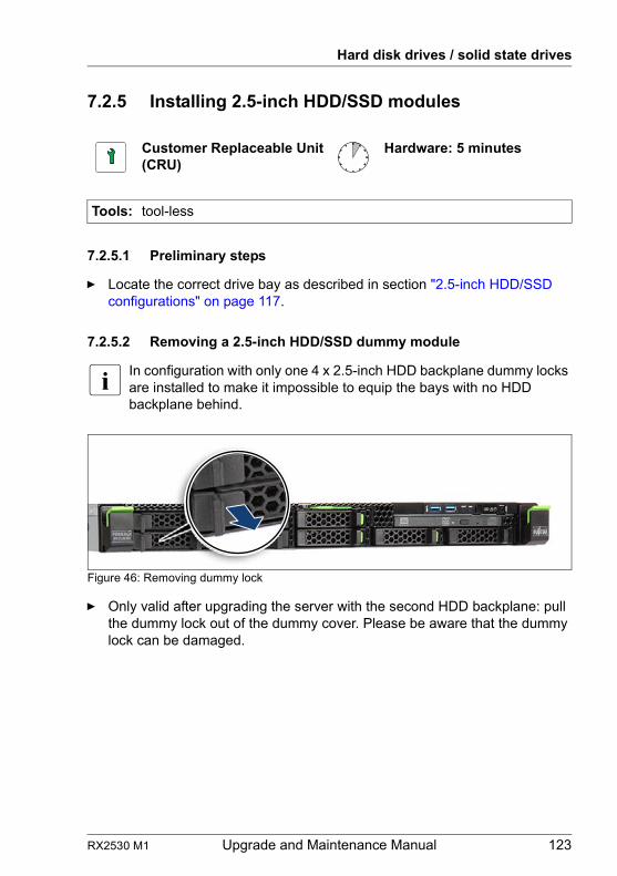
RX2530 M1 Upgrade and Maintenance Manual 123
Hard disk drives / solid state drives
7.2.5 Installing 2.5-inch HDD/SSD modules
7.2.5.1 Preliminary steps
Ê Locate the correct drive bay as described in section "2.5-inch HDD/SSD configurations" on page 117.
7.2.5.2 Removing a 2.5-inch HDD/SSD dummy module
I In configuration with only one 4 x 2.5-inch HDD backplane dummy locks are installed to make it impossible to equip the bays with no HDD backplane behind.
Figure 46: Removing dummy lock
Ê Only valid after upgrading the server with the second HDD backplane: pull the dummy lock out of the dummy cover. Please be aware that the dummy lock can be damaged.
Customer Replaceable Unit(CRU)
Hardware: 5 minutes
Tools: tool-less
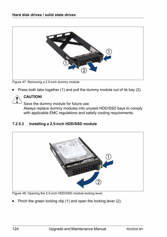
124 Upgrade and Maintenance Manual RX2530 M1
Hard disk drives / solid state drives
Figure 47: Removing a 2.5-inch dummy module
Ê Press both tabs together (1) and pull the dummy module out of its bay (2).
V CAUTION!
Save the dummy module for future use.Always replace dummy modules into unused HDD/SSD bays to comply with applicable EMC regulations and satisfy cooling requirements.
7.2.5.3 Installing a 2.5-inch HDD/SSD module
Figure 48: Opening the 2.5-inch HDD/SSD module locking lever
Ê Pinch the green locking clip (1) and open the locking lever (2).
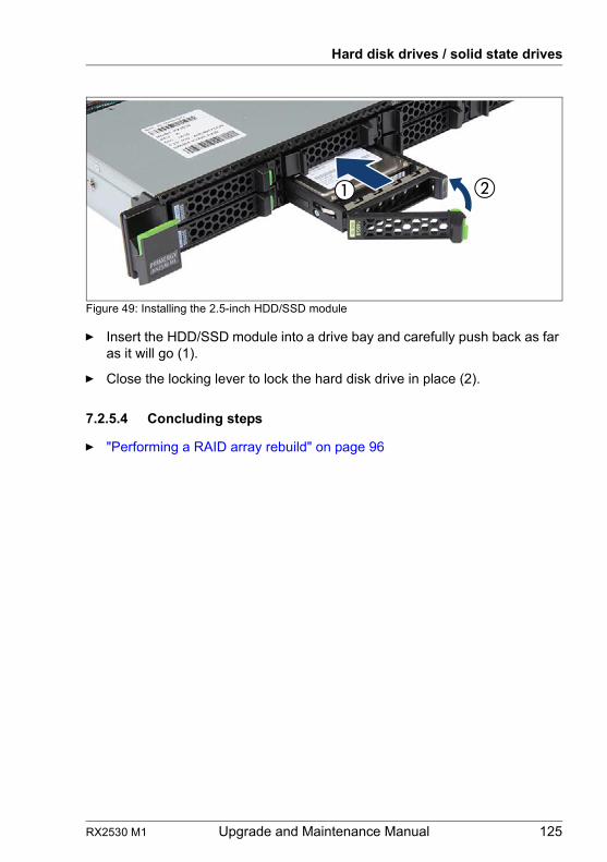
RX2530 M1 Upgrade and Maintenance Manual 125
Hard disk drives / solid state drives
Figure 49: Installing the 2.5-inch HDD/SSD module
Ê Insert the HDD/SSD module into a drive bay and carefully push back as far as it will go (1).
Ê Close the locking lever to lock the hard disk drive in place (2).
7.2.5.4 Concluding steps
Ê "Performing a RAID array rebuild" on page 96
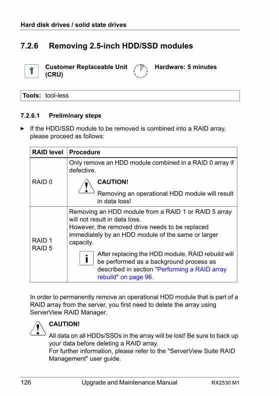
126 Upgrade and Maintenance Manual RX2530 M1
Hard disk drives / solid state drives
7.2.6 Removing 2.5-inch HDD/SSD modules
7.2.6.1 Preliminary steps
Ê If the HDD/SSD module to be removed is combined into a RAID array, please proceed as follows:
In order to permanently remove an operational HDD module that is part of a RAID array from the server, you first need to delete the array using ServerView RAID Manager.
V CAUTION!
All data on all HDDs/SSDs in the array will be lost! Be sure to back up your data before deleting a RAID array.For further information, please refer to the "ServerView Suite RAID Management" user guide.
Customer Replaceable Unit(CRU)
Hardware: 5 minutes
Tools: tool-less
RAID level Procedure
RAID 0
Only remove an HDD module combined in a RAID 0 array if defective.
V CAUTION!
Removing an operational HDD module will result in data loss!
RAID 1RAID 5
Removing an HDD module from a RAID 1 or RAID 5 array will not result in data loss.However, the removed drive needs to be replaced immediately by an HDD module of the same or larger capacity.
I After replacing the HDD module, RAID rebuild will be performed as a background process as described in section "Performing a RAID array rebuild" on page 96.
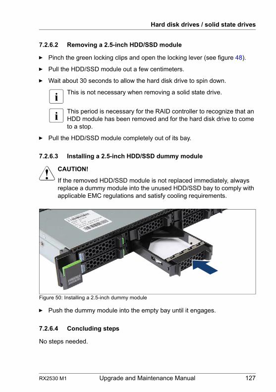
RX2530 M1 Upgrade and Maintenance Manual 127
Hard disk drives / solid state drives
7.2.6.2 Removing a 2.5-inch HDD/SSD module
Ê Pinch the green locking clips and open the locking lever (see figure 48).
Ê Pull the HDD/SSD module out a few centimeters.
Ê Wait about 30 seconds to allow the hard disk drive to spin down.
I This is not necessary when removing a solid state drive.
I This period is necessary for the RAID controller to recognize that an HDD module has been removed and for the hard disk drive to come to a stop.
Ê Pull the HDD/SSD module completely out of its bay.
7.2.6.3 Installing a 2.5-inch HDD/SSD dummy module
V CAUTION!
If the removed HDD/SSD module is not replaced immediately, always replace a dummy module into the unused HDD/SSD bay to comply with applicable EMC regulations and satisfy cooling requirements.
Figure 50: Installing a 2.5-inch dummy module
Ê Push the dummy module into the empty bay until it engages.
7.2.6.4 Concluding steps
No steps needed.
128 Upgrade and Maintenance Manual RX2530 M1
Hard disk drives / solid state drives
7.2.7 Replacing a 2.5-inch HDD/SSD module
V CAUTION!
● Only remove an HDD/SSD module during operation if the drive is not currently being accessed. Observe the indicators for the corresponding HDD/SSD modules, see section "Indicators on the hot-plug HDD/SSD module" on page 369.
● Under no circumstances should you remove an HDD/SSD module while the system is in operation if you are not sure that the drive is operated by a RAID controller and belongs to a disk array that is operating in RAID level 1, 1E, 10, 5, 50, 6 or 60.
An HDD/SSD module can only be replaced during operation in conjunction with a corresponding RAID configuration.
● All HDD/SSD modules (drives) must be uniquely identified so that they can be reinstalled in their original bays later. If this is not done, existing data can be lost.
7.2.7.1 Preliminary steps
Ê "Locating the defective server" on page 45
Ê "Locating the defective component" on page 47
Only applicable for removing intact HDD/SSD modules:
Ê Before removing a non-defective HDD/SSD module, put the drive into "Offline" mode using your RAID configuration software.
7.2.7.2 Removing the defective 2.5-inch HDD/SSD module
Ê Remove the HDD/SSD module as described in section "Removing 2.5-inch HDD/SSD modules" on page 126.
Customer Replaceable Unit(CRU)
Hardware: 5 minutes
Tools: tool-less
RX2530 M1 Upgrade and Maintenance Manual 129
Hard disk drives / solid state drives
7.2.7.3 Installing the new 2.5-inch HDD/SSD module
Ê Install the HDD/SSD module as described in section "Installing 2.5-inch HDD/SSD modules" on page 123.
7.2.7.4 Concluding steps
Ê "Performing a RAID array rebuild" on page 96
7.2.8 Replacing the 4 x 2.5-inch HDD backplane
7.2.8.1 Preliminary steps
Ê "Locating the defective server" on page 45
Ê "Shutting down the server" on page 48
Ê "Disconnecting the server from the mains" on page 49
Ê "Getting access to the component" on page 49
Ê Release all HDD/SSD modules and pull them out a few centimeters, see section "Removing 2.5-inch HDD/SSD modules" on page 126
I The HDD/SSD modules need not to be removed completely. But if you want to remove them nevertheless, check if all HDD/SSD modules are uniquely identified so that you can reinsert them into their original bays.
Field Replaceable Unit(FRU)
Hardware: 10 minutes
Tools: tool-less
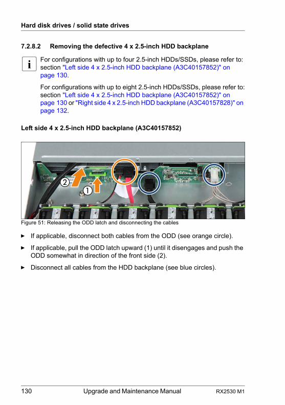
130 Upgrade and Maintenance Manual RX2530 M1
Hard disk drives / solid state drives
7.2.8.2 Removing the defective 4 x 2.5-inch HDD backplane
I For configurations with up to four 2.5-inch HDDs/SSDs, please refer to:section "Left side 4 x 2.5-inch HDD backplane (A3C40157852)" on page 130.
For configurations with up to eight 2.5-inch HDDs/SSDs, please refer to:section "Left side 4 x 2.5-inch HDD backplane (A3C40157852)" on page 130 or "Right side 4 x 2.5-inch HDD backplane (A3C40157828)" on page 132.
Left side 4 x 2.5-inch HDD backplane (A3C40157852)
Figure 51: Releasing the ODD latch and disconnecting the cables
Ê If applicable, disconnect both cables from the ODD (see orange circle).
Ê If applicable, pull the ODD latch upward (1) until it disengages and push the ODD somewhat in direction of the front side (2).
Ê Disconnect all cables from the HDD backplane (see blue circles).
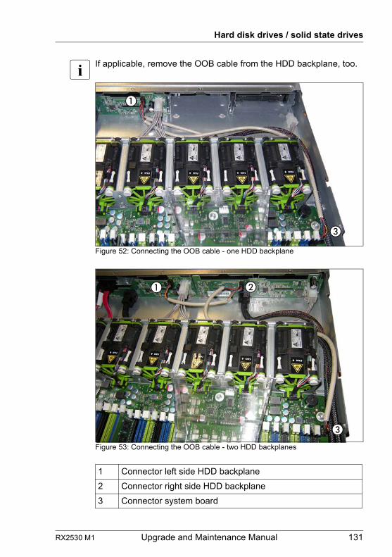
RX2530 M1 Upgrade and Maintenance Manual 131
Hard disk drives / solid state drives
I If applicable, remove the OOB cable from the HDD backplane, too.
Figure 52: Connecting the OOB cable - one HDD backplane
Figure 53: Connecting the OOB cable - two HDD backplanes
1 Connector left side HDD backplane
2 Connector right side HDD backplane
3 Connector system board
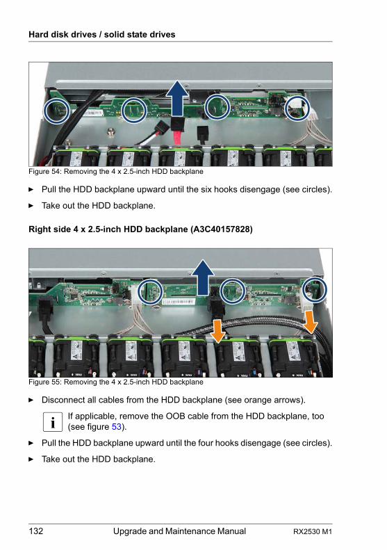
132 Upgrade and Maintenance Manual RX2530 M1
Hard disk drives / solid state drives
Figure 54: Removing the 4 x 2.5-inch HDD backplane
Ê Pull the HDD backplane upward until the six hooks disengage (see circles).
Ê Take out the HDD backplane.
Right side 4 x 2.5-inch HDD backplane (A3C40157828)
Figure 55: Removing the 4 x 2.5-inch HDD backplane
Ê Disconnect all cables from the HDD backplane (see orange arrows).
I If applicable, remove the OOB cable from the HDD backplane, too (see figure 53).
Ê Pull the HDD backplane upward until the four hooks disengage (see circles).
Ê Take out the HDD backplane.
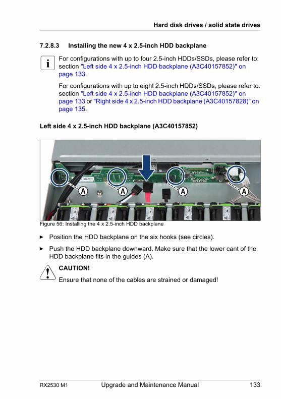
RX2530 M1 Upgrade and Maintenance Manual 133
Hard disk drives / solid state drives
7.2.8.3 Installing the new 4 x 2.5-inch HDD backplane
I For configurations with up to four 2.5-inch HDDs/SSDs, please refer to:section "Left side 4 x 2.5-inch HDD backplane (A3C40157852)" on page 133.
For configurations with up to eight 2.5-inch HDDs/SSDs, please refer to:section "Left side 4 x 2.5-inch HDD backplane (A3C40157852)" on page 133 or "Right side 4 x 2.5-inch HDD backplane (A3C40157828)" on page 135.
Left side 4 x 2.5-inch HDD backplane (A3C40157852)
Figure 56: Installing the 4 x 2.5-inch HDD backplane
Ê Position the HDD backplane on the six hooks (see circles).
Ê Push the HDD backplane downward. Make sure that the lower cant of the HDD backplane fits in the guides (A).
V CAUTION!
Ensure that none of the cables are strained or damaged!
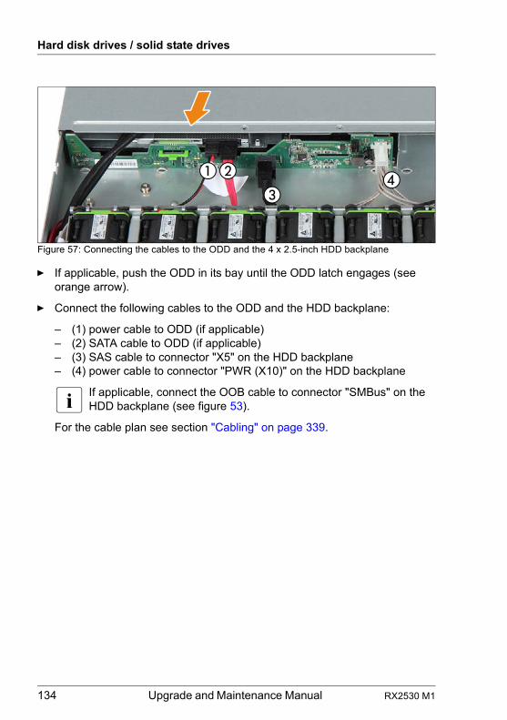
134 Upgrade and Maintenance Manual RX2530 M1
Hard disk drives / solid state drives
Figure 57: Connecting the cables to the ODD and the 4 x 2.5-inch HDD backplane
Ê If applicable, push the ODD in its bay until the ODD latch engages (see orange arrow).
Ê Connect the following cables to the ODD and the HDD backplane:
– (1) power cable to ODD (if applicable)– (2) SATA cable to ODD (if applicable)– (3) SAS cable to connector "X5" on the HDD backplane– (4) power cable to connector "PWR (X10)" on the HDD backplane
I If applicable, connect the OOB cable to connector "SMBus" on the HDD backplane (see figure 53).
For the cable plan see section "Cabling" on page 339.
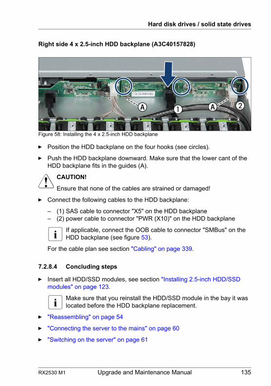
RX2530 M1 Upgrade and Maintenance Manual 135
Hard disk drives / solid state drives
Right side 4 x 2.5-inch HDD backplane (A3C40157828)
Figure 58: Installing the 4 x 2.5-inch HDD backplane
Ê Position the HDD backplane on the four hooks (see circles).
Ê Push the HDD backplane downward. Make sure that the lower cant of the HDD backplane fits in the guides (A).
V CAUTION!
Ensure that none of the cables are strained or damaged!
Ê Connect the following cables to the HDD backplane:
– (1) SAS cable to connector "X5" on the HDD backplane– (2) power cable to connector "PWR (X10)" on the HDD backplane
I If applicable, connect the OOB cable to connector "SMBus" on the HDD backplane (see figure 53).
For the cable plan see section "Cabling" on page 339.
7.2.8.4 Concluding steps
Ê Insert all HDD/SSD modules, see section "Installing 2.5-inch HDD/SSD modules" on page 123.
I Make sure that you reinstall the HDD/SSD module in the bay it was located before the HDD backplane replacement.
Ê "Reassembling" on page 54
Ê "Connecting the server to the mains" on page 60
Ê "Switching on the server" on page 61
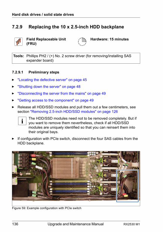
136 Upgrade and Maintenance Manual RX2530 M1
Hard disk drives / solid state drives
7.2.9 Replacing the 10 x 2.5-inch HDD backplane
7.2.9.1 Preliminary steps
Ê "Locating the defective server" on page 45
Ê "Shutting down the server" on page 48
Ê "Disconnecting the server from the mains" on page 49
Ê "Getting access to the component" on page 49
Ê Release all HDD/SSD modules and pull them out a few centimeters, see section "Removing 2.5-inch HDD/SSD modules" on page 126
I The HDD/SSD modules need not to be removed completely. But if you want to remove them nevertheless, check if all HDD/SSD modules are uniquely identified so that you can reinsert them into their original bays.
Ê If configuration with PCIe switch, disconnect the four SAS cables from the HDD backplane.
Figure 59: Example configuration with PCIe switch
Field Replaceable Unit(FRU)
Hardware: 15 minutes
Tools: Phillips PH2 / (+) No. 2 screw driver (for removing/installing SAS expander board)
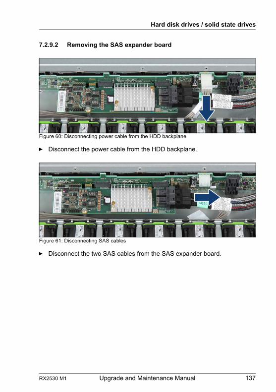
RX2530 M1 Upgrade and Maintenance Manual 137
Hard disk drives / solid state drives
7.2.9.2 Removing the SAS expander board
Figure 60: Disconnecting power cable from the HDD backplane
Ê Disconnect the power cable from the HDD backplane.
Figure 61: Disconnecting SAS cables
Ê Disconnect the two SAS cables from the SAS expander board.
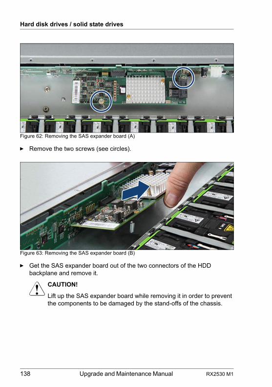
138 Upgrade and Maintenance Manual RX2530 M1
Hard disk drives / solid state drives
Figure 62: Removing the SAS expander board (A)
Ê Remove the two screws (see circles).
Figure 63: Removing the SAS expander board (B)
Ê Get the SAS expander board out of the two connectors of the HDD backplane and remove it.
V CAUTION!
Lift up the SAS expander board while removing it in order to prevent the components to be damaged by the stand-offs of the chassis.
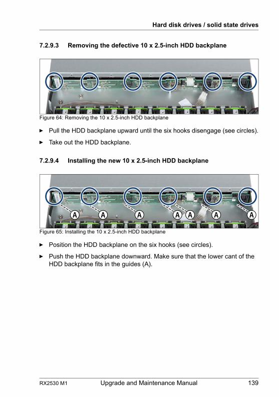
RX2530 M1 Upgrade and Maintenance Manual 139
Hard disk drives / solid state drives
7.2.9.3 Removing the defective 10 x 2.5-inch HDD backplane
Figure 64: Removing the 10 x 2.5-inch HDD backplane
Ê Pull the HDD backplane upward until the six hooks disengage (see circles).
Ê Take out the HDD backplane.
7.2.9.4 Installing the new 10 x 2.5-inch HDD backplane
Figure 65: Installing the 10 x 2.5-inch HDD backplane
Ê Position the HDD backplane on the six hooks (see circles).
Ê Push the HDD backplane downward. Make sure that the lower cant of the HDD backplane fits in the guides (A).
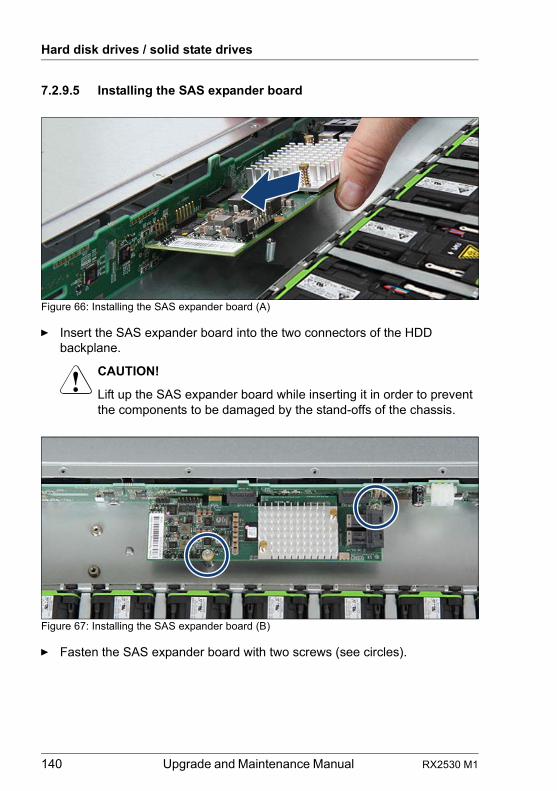
140 Upgrade and Maintenance Manual RX2530 M1
Hard disk drives / solid state drives
7.2.9.5 Installing the SAS expander board
Figure 66: Installing the SAS expander board (A)
Ê Insert the SAS expander board into the two connectors of the HDD backplane.
V CAUTION!
Lift up the SAS expander board while inserting it in order to prevent the components to be damaged by the stand-offs of the chassis.
Figure 67: Installing the SAS expander board (B)
Ê Fasten the SAS expander board with two screws (see circles).
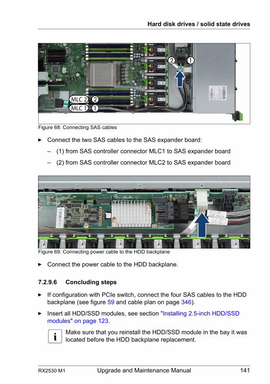
RX2530 M1 Upgrade and Maintenance Manual 141
Hard disk drives / solid state drives
Figure 68: Connecting SAS cables
Ê Connect the two SAS cables to the SAS expander board:
– (1) from SAS controller connector MLC1 to SAS expander board
– (2) from SAS controller connector MLC2 to SAS expander board
Figure 69: Connecting power cable to the HDD backplane
Ê Connect the power cable to the HDD backplane.
7.2.9.6 Concluding steps
Ê If configuration with PCIe switch, connect the four SAS cables to the HDD backplane (see figure 59 and cable plan on page 346).
Ê Insert all HDD/SSD modules, see section "Installing 2.5-inch HDD/SSD modules" on page 123.
I Make sure that you reinstall the HDD/SSD module in the bay it was located before the HDD backplane replacement.
MLC 1MLC 2
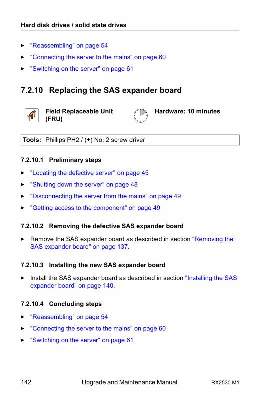
142 Upgrade and Maintenance Manual RX2530 M1
Hard disk drives / solid state drives
Ê "Reassembling" on page 54
Ê "Connecting the server to the mains" on page 60
Ê "Switching on the server" on page 61
7.2.10 Replacing the SAS expander board
7.2.10.1 Preliminary steps
Ê "Locating the defective server" on page 45
Ê "Shutting down the server" on page 48
Ê "Disconnecting the server from the mains" on page 49
Ê "Getting access to the component" on page 49
7.2.10.2 Removing the defective SAS expander board
Ê Remove the SAS expander board as described in section "Removing the SAS expander board" on page 137.
7.2.10.3 Installing the new SAS expander board
Ê Install the SAS expander board as described in section "Installing the SAS expander board" on page 140.
7.2.10.4 Concluding steps
Ê "Reassembling" on page 54
Ê "Connecting the server to the mains" on page 60
Ê "Switching on the server" on page 61
Field Replaceable Unit(FRU)
Hardware: 10 minutes
Tools: Phillips PH2 / (+) No. 2 screw driver
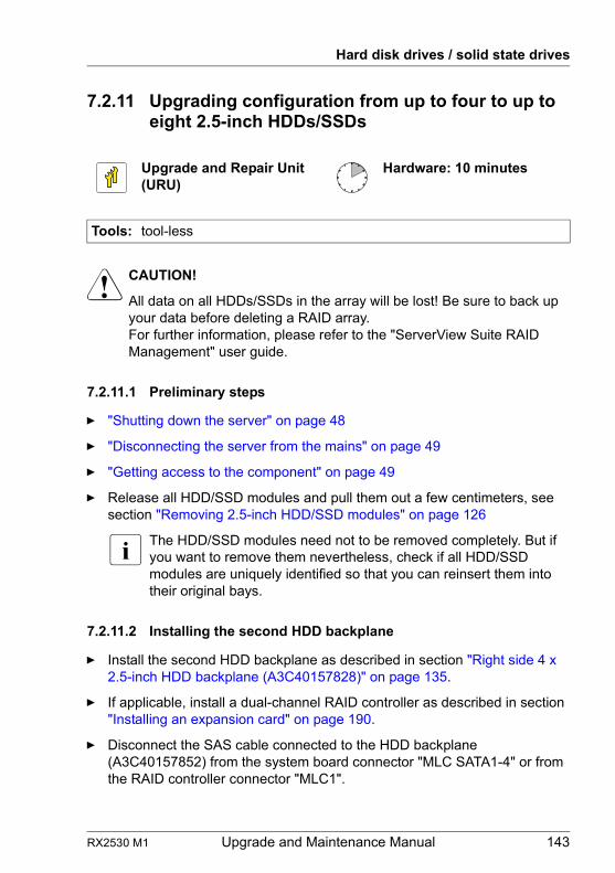
RX2530 M1 Upgrade and Maintenance Manual 143
Hard disk drives / solid state drives
7.2.11 Upgrading configuration from up to four to up to eight 2.5-inch HDDs/SSDs
V CAUTION!
All data on all HDDs/SSDs in the array will be lost! Be sure to back up your data before deleting a RAID array.For further information, please refer to the "ServerView Suite RAID Management" user guide.
7.2.11.1 Preliminary steps
Ê "Shutting down the server" on page 48
Ê "Disconnecting the server from the mains" on page 49
Ê "Getting access to the component" on page 49
Ê Release all HDD/SSD modules and pull them out a few centimeters, see section "Removing 2.5-inch HDD/SSD modules" on page 126
I The HDD/SSD modules need not to be removed completely. But if you want to remove them nevertheless, check if all HDD/SSD modules are uniquely identified so that you can reinsert them into their original bays.
7.2.11.2 Installing the second HDD backplane
Ê Install the second HDD backplane as described in section "Right side 4 x 2.5-inch HDD backplane (A3C40157828)" on page 135.
Ê If applicable, install a dual-channel RAID controller as described in section "Installing an expansion card" on page 190.
Ê Disconnect the SAS cable connected to the HDD backplane (A3C40157852) from the system board connector "MLC SATA1-4" or from the RAID controller connector "MLC1".
Upgrade and Repair Unit(URU)
Hardware: 10 minutes
Tools: tool-less
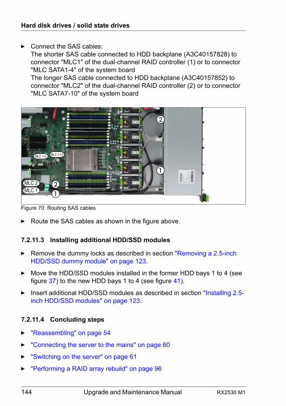
144 Upgrade and Maintenance Manual RX2530 M1
Hard disk drives / solid state drives
Ê Connect the SAS cables:The shorter SAS cable connected to HDD backplane (A3C40157828) to connector "MLC1" of the dual-channel RAID controller (1) or to connector "MLC SATA1-4" of the system boardThe longer SAS cable connected to HDD backplane (A3C40157852) to connector "MLC2" of the dual-channel RAID controller (2) or to connector "MLC SATA7-10" of the system board
Figure 70: Routing SAS cables
Ê Route the SAS cables as shown in the figure above.
7.2.11.3 Installing additional HDD/SSD modules
Ê Remove the dummy locks as described in section "Removing a 2.5-inch HDD/SSD dummy module" on page 123.
Ê Move the HDD/SSD modules installed in the former HDD bays 1 to 4 (see figure 37) to the new HDD bays 1 to 4 (see figure 41).
Ê Insert additional HDD/SSD modules as described in section "Installing 2.5-inch HDD/SSD modules" on page 123.
7.2.11.4 Concluding steps
Ê "Reassembling" on page 54
Ê "Connecting the server to the mains" on page 60
Ê "Switching on the server" on page 61
Ê "Performing a RAID array rebuild" on page 96
MLC 2MLC 1
MLC 7-10MLC 1-4
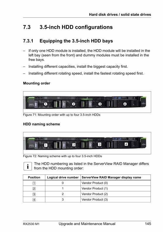
RX2530 M1 Upgrade and Maintenance Manual 145
Hard disk drives / solid state drives
7.3 3.5-inch HDD configurations
7.3.1 Equipping the 3.5-inch HDD bays
– If only one HDD module is installed, the HDD module will be installed in the left bay (seen from the front) and dummy modules must be installed in the free bays.
– Installing different capacities, install the biggest capacity first.
– Installing different rotating speed, install the fastest rotating speed first.
Mounting order
Figure 71: Mounting order with up to four 3.5-inch HDDs
HDD naming scheme
Figure 72: Naming scheme with up to four 3.5-inch HDDs
I The HDD numbering as listed in the ServerView RAID Manager differs from the HDD mounting order:
Position Logical drive number ServerView RAID Manager display name
[1] 0 Vendor Product (0)
[2] 1 Vendor Product (1)
[3] 2 Vendor Product (2)
[4] 3 Vendor Product (3)
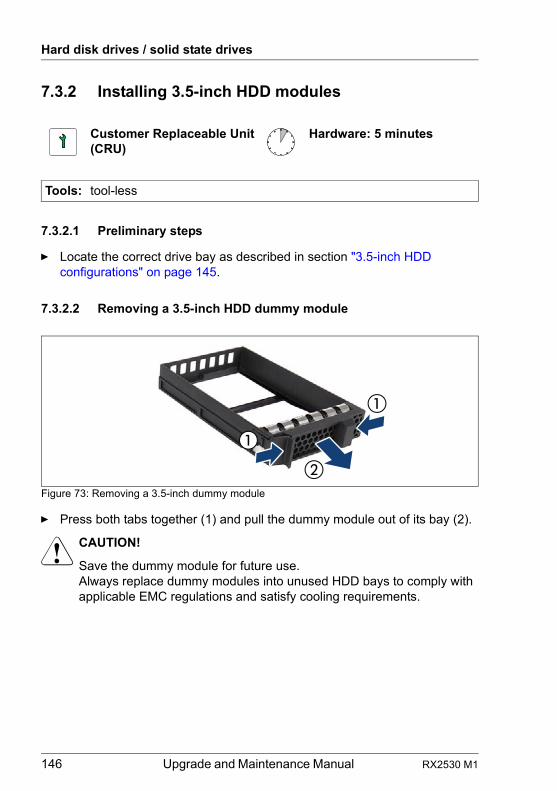
146 Upgrade and Maintenance Manual RX2530 M1
Hard disk drives / solid state drives
7.3.2 Installing 3.5-inch HDD modules
7.3.2.1 Preliminary steps
Ê Locate the correct drive bay as described in section "3.5-inch HDD configurations" on page 145.
7.3.2.2 Removing a 3.5-inch HDD dummy module
Figure 73: Removing a 3.5-inch dummy module
Ê Press both tabs together (1) and pull the dummy module out of its bay (2).
V CAUTION!
Save the dummy module for future use.Always replace dummy modules into unused HDD bays to comply with applicable EMC regulations and satisfy cooling requirements.
Customer Replaceable Unit(CRU)
Hardware: 5 minutes
Tools: tool-less
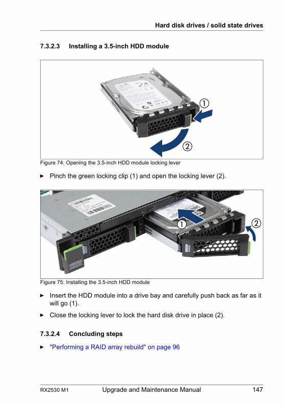
RX2530 M1 Upgrade and Maintenance Manual 147
Hard disk drives / solid state drives
7.3.2.3 Installing a 3.5-inch HDD module
Figure 74: Opening the 3.5-inch HDD module locking lever
Ê Pinch the green locking clip (1) and open the locking lever (2).
Figure 75: Installing the 3.5-inch HDD module
Ê Insert the HDD module into a drive bay and carefully push back as far as it will go (1).
Ê Close the locking lever to lock the hard disk drive in place (2).
7.3.2.4 Concluding steps
Ê "Performing a RAID array rebuild" on page 96

148 Upgrade and Maintenance Manual RX2530 M1
Hard disk drives / solid state drives
7.3.3 Removing 3.5-inch HDD modules
7.3.3.1 Preliminary steps
Ê If the HDD module to be removed is combined into a RAID array, please proceed as follows:
In order to permanently remove an operational HDD module that is part of a RAID array from the server, you first need to delete the array using ServerView RAID Manager.
V CAUTION!
All data on all HDDs in the array will be lost! Be sure to back up your data before deleting a RAID array.For further information, please refer to the "ServerView Suite RAID Management" user guide.
Customer Replaceable Unit(CRU)
Hardware: 5 minutes
Tools: tool-less
RAID level Procedure
RAID 0
Only remove an HDD module combined in a RAID 0 array if defective.
V CAUTION!
Removing an operational HDD module will result in data loss!
RAID 1RAID 5
Removing an HDD module from a RAID 1 or RAID 5 array will not result in data loss.However, the removed drive needs to be replaced immediately by an HDD module of the same or larger capacity.
I After replacing the HDD module, RAID rebuild will be performed as a background process as described in section "Performing a RAID array rebuild" on page 96.
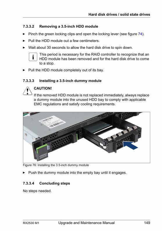
RX2530 M1 Upgrade and Maintenance Manual 149
Hard disk drives / solid state drives
7.3.3.2 Removing a 3.5-inch HDD module
Ê Pinch the green locking clips and open the locking lever (see figure 74).
Ê Pull the HDD module out a few centimeters.
Ê Wait about 30 seconds to allow the hard disk drive to spin down.
I This period is necessary for the RAID controller to recognize that an HDD module has been removed and for the hard disk drive to come to a stop.
Ê Pull the HDD module completely out of its bay.
7.3.3.3 Installing a 3.5-inch dummy module
V CAUTION!
If the removed HDD module is not replaced immediately, always replace a dummy module into the unused HDD bay to comply with applicable EMC regulations and satisfy cooling requirements.
Figure 76: Installing the 3.5-inch dummy module
Ê Push the dummy module into the empty bay until it engages.
7.3.3.4 Concluding steps
No steps needed.
150 Upgrade and Maintenance Manual RX2530 M1
Hard disk drives / solid state drives
7.3.4 Replacing a 3.5-inch HDD module
V CAUTION!
● Only remove an HDD module during operation if the drive is not currently being accessed. Observe the indicators on the HDD module, see section "Indicators on the hot-plug HDD/SSD module" on page 369.
● Under no circumstances should you remove an HDD module while the system is in operation if you are not sure that the drive is operated by a RAID controller and belongs to a disk array that is operating in RAID level 1, 1E, 10, 5, 50, 6 or 60.
An HDD module can only be replaced during operation in conjunction with a corresponding RAID configuration.
● All HDD modules (drives) must be uniquely identified so that they can be reinstalled in their original bays later. If this is not done, existing data can be lost.
7.3.4.1 Preliminary steps
Ê "Locating the defective server" on page 45
Ê "Locating the defective component" on page 47
Only applicable for removing intact HDD modules:
Ê Before removing a non-defective HDD module, put the drive into "Offline" mode using your RAID configuration software.
I For further information, please refer to the "ServerView Suite RAID Management" user guide.
Customer Replaceable Unit(CRU)
Hardware: 5 minutes
Tools: tool-less
RX2530 M1 Upgrade and Maintenance Manual 151
Hard disk drives / solid state drives
7.3.4.2 Removing the defective 3.5-inch HDD module
Ê Remove the HDD module as described in section "Removing a 3.5-inch HDD module" on page 149.
7.3.4.3 Installing the new 3.5-inch HDD module
Ê Install the HDD module as described in section "Installing a 3.5-inch HDD module" on page 147.
7.3.4.4 Concluding steps
Ê "Performing a RAID array rebuild" on page 96
7.3.5 Replacing the 3.5-inch HDD backplane
7.3.5.1 Preliminary steps
Ê "Locating the defective server" on page 45
Ê "Shutting down the server" on page 48
Ê "Disconnecting the server from the mains" on page 49
Ê "Getting access to the component" on page 49
Ê Release all HDD modules and pull them out a few centimeters, see section "Removing a 3.5-inch HDD module" on page 149
I The HDD modules need not to be removed completely. But if you want to remove them nevertheless, check if all HDD modules are uniquely identified so that you can reinsert them into their original bays.
Field Replaceable Unit(FRU)
Hardware: 10 minutes
Tools: tool-less
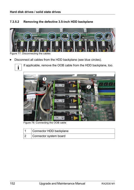
152 Upgrade and Maintenance Manual RX2530 M1
Hard disk drives / solid state drives
7.3.5.2 Removing the defective 3.5-inch HDD backplane
Figure 77: Disconnecting the cables
Ê Disconnect all cables from the HDD backplane (see blue circles).
I If applicable, remove the OOB cable from the HDD backplane, too.
Figure 78: Connecting the OOB cable
1 Connector HDD backplane
2 Connector system board
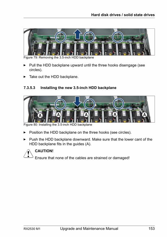
RX2530 M1 Upgrade and Maintenance Manual 153
Hard disk drives / solid state drives
Figure 79: Removing the 3.5-inch HDD backplane
Ê Pull the HDD backplane upward until the three hooks disengage (see circles).
Ê Take out the HDD backplane.
7.3.5.3 Installing the new 3.5-inch HDD backplane
Figure 80: Installing the 3.5-inch HDD backplane
Ê Position the HDD backplane on the three hooks (see circles).
Ê Push the HDD backplane downward. Make sure that the lower cant of the HDD backplane fits in the guides (A).
V CAUTION!
Ensure that none of the cables are strained or damaged!
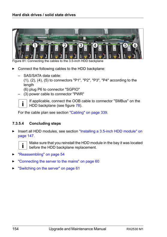
154 Upgrade and Maintenance Manual RX2530 M1
Hard disk drives / solid state drives
Figure 81: Connecting the cables to the 3.5-inch HDD backplane
Ê Connect the following cables to the HDD backplane:
– SAS/SATA data cable:(1), (2), (4), (5) to connectors "P1", "P2", "P3", "P4" according to the length(6) plug P6 to connector "SGPIO"
– (3) power cable to connector "PWR"
I If applicable, connect the OOB cable to connector "SMBus" on the HDD backplane (see figure 78).
For the cable plan see section "Cabling" on page 339.
7.3.5.4 Concluding steps
Ê Insert all HDD modules, see section "Installing a 3.5-inch HDD module" on page 147.
I Make sure that you reinstall the HDD module in the bay it was located before the HDD backplane replacement.
Ê "Reassembling" on page 54
Ê "Connecting the server to the mains" on page 60
Ê "Switching on the server" on page 61
RX2530 M1 Upgrade and Maintenance Manual 155
8 Fans
Safety notes
V CAUTION!
● Do not damage or modify internal cables or devices. Doing so may cause a device failure, fire, or electric shock.
● Devices inside the server remain hot after shutdown. Wait for a while after shutdown before installing or removing internal options.
● The circuit boards and soldered parts of internal options are exposed and can be damaged by static electricity. Before handling them, first touch a metal part of the server to discharge static electricity from your body.
● Do not touch the circuitry on boards or soldered parts. Hold the metallic areas or the edges of the circuit boards.
● If devices are installed or disassembled using methods other than those outlined in this chapter, the warranty will be invalidated.
● The installation indicated on this note is sometimes changed to the kind of possible options without notice.
● For further safety information, please refer to chapter "Important information" on page 33.
8.1 Basic information
Base units are supplied with four hot-plug fan modules (single CPU configuration and depending on CPU type) or eight hot-plug fan modules (two CPUs configuration and depending on CPU type). Each fan module consists of two fans, implemented in one housing.
Base units with four fan modules operate in a 1 of 4 redundancy, base units with eight fan modules operate in a 1 of 8 redundancy. In other words, if one of the four or eight fan modules fails, the system will operate without any problem. The failed fan module can be exchanged without shutting down the server (hot-plug).
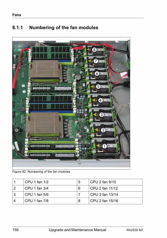
156 Upgrade and Maintenance Manual RX2530 M1
Fans
8.1.1 Numbering of the fan modules
Figure 82: Numbering of the fan modules
1 CPU 1 fan 1/2 5 CPU 2 fan 9/10
2 CPU 1 fan 3/4 6 CPU 2 fan 11/12
3 CPU 1 fan 5/6 7 CPU 2 fan 13/14
4 CPU 1 fan 7/8 8 CPU 2 fan 15/16
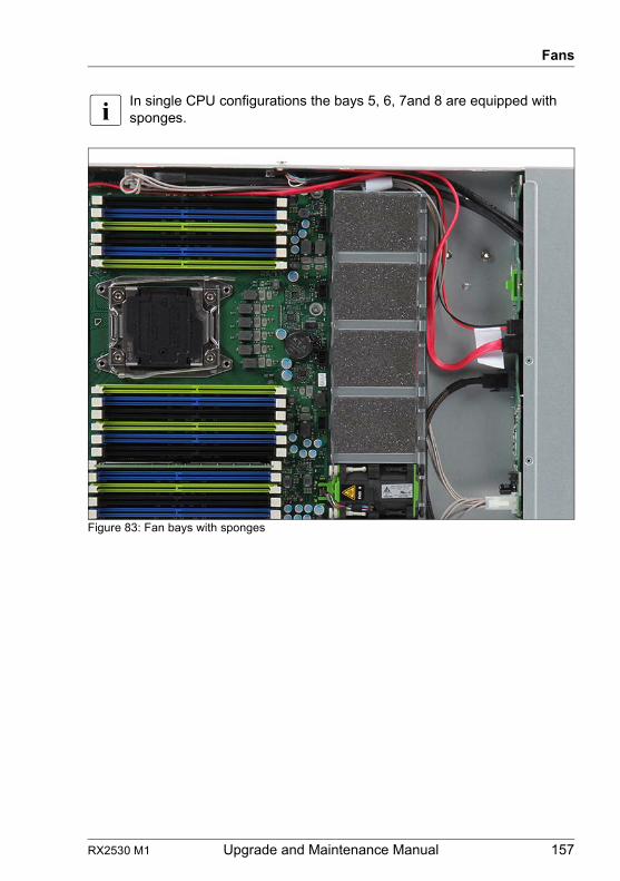
RX2530 M1 Upgrade and Maintenance Manual 157
Fans
I In single CPU configurations the bays 5, 6, 7and 8 are equipped with sponges.
Figure 83: Fan bays with sponges
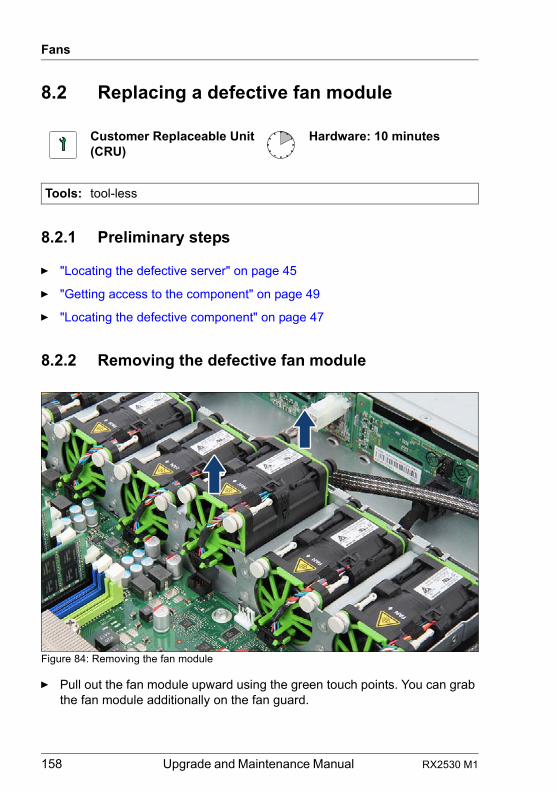
158 Upgrade and Maintenance Manual RX2530 M1
Fans
8.2 Replacing a defective fan module
8.2.1 Preliminary steps
Ê "Locating the defective server" on page 45
Ê "Getting access to the component" on page 49
Ê "Locating the defective component" on page 47
8.2.2 Removing the defective fan module
Figure 84: Removing the fan module
Ê Pull out the fan module upward using the green touch points. You can grab the fan module additionally on the fan guard.
Customer Replaceable Unit(CRU)
Hardware: 10 minutes
Tools: tool-less
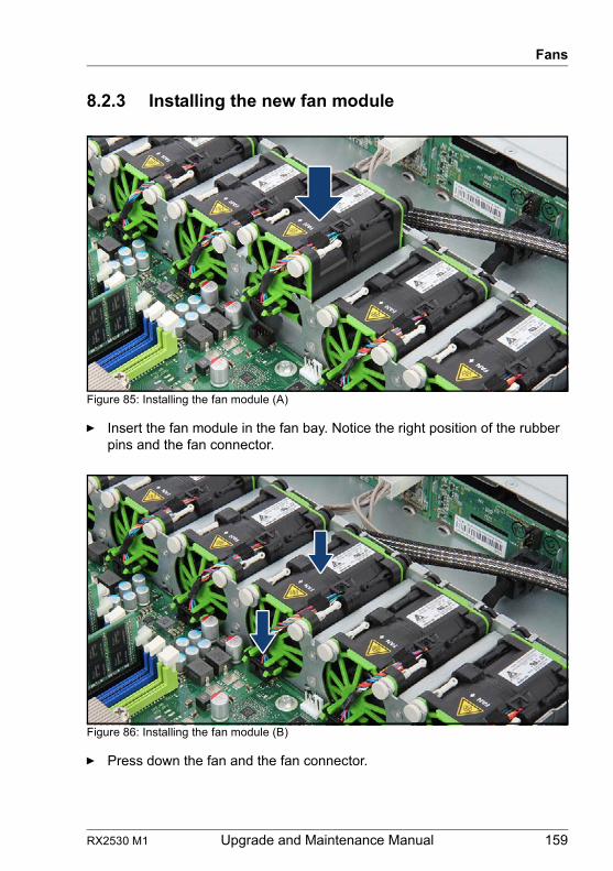
RX2530 M1 Upgrade and Maintenance Manual 159
Fans
8.2.3 Installing the new fan module
Figure 85: Installing the fan module (A)
Ê Insert the fan module in the fan bay. Notice the right position of the rubber pins and the fan connector.
Figure 86: Installing the fan module (B)
Ê Press down the fan and the fan connector.
160 Upgrade and Maintenance Manual RX2530 M1
Fans
8.2.4 Concluding steps
Ê "Reassembling" on page 54
Ê "Performing a fan test after replacing a defective fan" on page 100
RX2530 M1 Upgrade and Maintenance Manual 161
9 Expansion cards and backup units
Safety notes
V CAUTION!
● Do not damage or modify internal cables or devices. Doing so may cause a device failure, fire, or electric shock.
● Devices and components inside the server remain hot after shutdown. After shutting down the server, wait for hot components to cool down before installing or removing internal options.
● Circuit boards and soldered parts of internal options are exposed and can be damaged by static electricity. Always discharge static build-up (e.g. by touching a grounded object) before handling electrostatic-sensitive devices (ESDs).
● Do not touch the circuitry on boards or soldered parts. Hold circuit boards by their metallic areas or edges.
● If devices are installed or disassembled using methods other than those outlined in this chapter, the warranty will be invalidated.
● For further safety information, please refer to chapter "Important information" on page 33.
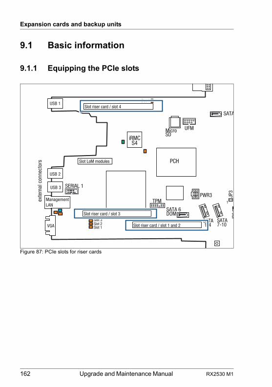
162 Upgrade and Maintenance Manual RX2530 M1
Expansion cards and backup units
9.1 Basic information
9.1.1 Equipping the PCIe slots
Figure 87: PCIe slots for riser cards
iRMCS4
exte
rnal
con
nect
ors
INDICATE
TPM
VGA
USB 2
USB 3
ManagementLAN
Slot riser card / slot 1 and 2
PCH
JP3
SATA 1-4
USB 1
Slot riser card / slot 3
Slot riser card / slot 4
Slot 3
UFM
SERIAL 1
Slot 2Slot 1
Slot 4
PWR3
MicroSD
SATA7-10
SATA 6 DOM
SATA
JP2
1
Slot LoM modules
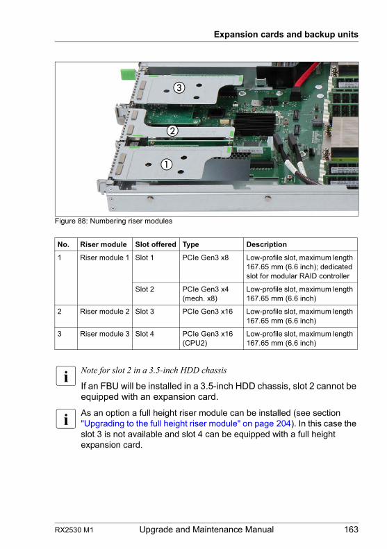
RX2530 M1 Upgrade and Maintenance Manual 163
Expansion cards and backup units
Figure 88: Numbering riser modules
I Note for slot 2 in a 3.5-inch HDD chassis
If an FBU will be installed in a 3.5-inch HDD chassis, slot 2 cannot be equipped with an expansion card.
I As an option a full height riser module can be installed (see section "Upgrading to the full height riser module" on page 204). In this case the slot 3 is not available and slot 4 can be equipped with a full height expansion card.
No. Riser module Slot offered Type Description
1 Riser module 1 Slot 1 PCIe Gen3 x8 Low-profile slot, maximum length 167.65 mm (6.6 inch); dedicated slot for modular RAID controller
Slot 2 PCIe Gen3 x4 (mech. x8)
Low-profile slot, maximum length 167.65 mm (6.6 inch)
2 Riser module 2 Slot 3 PCIe Gen3 x16 Low-profile slot, maximum length 167.65 mm (6.6 inch)
3 Riser module 3 Slot 4 PCIe Gen3 x16 (CPU2)
Low-profile slot, maximum length 167.65 mm (6.6 inch)
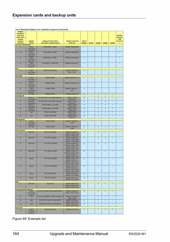
164 Upgrade and Maintenance Manual RX2530 M1
Expansion cards and backup units
Figure 89: Example list
List of Released Adapters incl. Installation sequence and priorityAdapter
InstallationSequence
Order within Adapter
Category(Cluster)
AdapterVendor
Adapter Product NameDescription (Softwarepool)
Adapter Customer Order No.
Max #Adapter Slot#1 Slot#2 Slot#3 Slot#4
Slot#X2Dynamic
LOMconnecto
r
1 FujitsuTechnologySolutions
PLAN EM 2 x 1GB T S26361-F5302-E201 1 - - - - 1
2 FujitsuTechnologySolutions
PLAN EM 4 x 1GB T S26361-F5302-E401 1 - - - - 1
3 FujitsuTechnologySolutions
PLAN EM 2 x 10GB T S26361-F5302-E210 1 - - - - 1
4 FujitsuTechnologySolutions
PLAN EM 2 x 10GB SFP S26361-F5302-E211 1 - - - - 1
1 FujitsuTechnologySolutions
PPCI EP x16 Switch S26361-F5267-E1 / E201 / L501
1 - - 1 -
1 FujitsuTechnologySolutions
PRAID EP400i S26361-F5243-E1 / L1 1 1 - - - -
2 FujitsuTechnologySolutions
PRAID EP420i S26361-F5243-E2 / L2 1 1 - - - -
3 FujitsuTechnologySolutions
PRAID CP400i S26361-F3842-E1 / -L501
1 1 - - - -
4 LSI Logic PRAID EP420e S26361-F3847-E2 2 - 2 3 1 -
1 MellanoxTechnology
IB HCA 40Gb 1 port QDR enhanced S26361-F4475-E103/L103
2 - 2 3 1 -
2 MellanoxTechnology
IB HCA 40Gb 2 port QDR enhanced S26361-F4475-E203/L203
2 - 2 3 1 -
3 MellanoxTechnology
IB HCA 56Gb 1 port FDR S26361-F4533-E102/L102
2 - 2 3 1 -
4 MellanoxTechnology
IB HCA 56Gb 2 port FDR S26361-F4533-E202/L202
2 - 2 3 1 -
5 Intel PIB EP QLE7340e S26361-F4475-E122/L122
2 - 2 3 1 -
6 Intel PIB EP QLE7342e S26361-F4475-E222/L222
2 - 2 3 1 -
1 FujitsuTechnologySolutions
PSAS CP400i S26361-F3842-E2 / -L502
1 1 - - - -
2 LSI Logic PSAS CP400e S26361-F3842-E2 / -L502
2 - 2 3 1 -
1 EMULEX PFC EP LPe16000 S26361-F4994-E1/S26361-F4994-E201/S26361-F4994-L501
2 - 2 3 1 -
2 EMULEX PFC EP LPe16002 S26361-F4994-E2/S26361-F4994-E202/S26361-F4994-L502
2 - 2 3 1 -
3 EMULEX FC CTRL LPe12002 S26361-F3961-E2 / S26361-F3961-E202 /
S26361-F3961-L2 / S26361-F3961-L202
2 - 2 3 1 -
4 EMULEX FC CTRL LPe1250 S26361-F3961-E1 / S26361-F3961-E201 /
S26361-F3961-L1 / S26361-F3961-L201
2 - 2 3 1 -
5 Qlogic FC CTRL QLE2560 S26361-F3631-E1 / S26361-F3631-L1 /
S26361-F3631-E201 / S26361-F3631-L201
2 - 2 3 1 -
6 Qlogic FC CTRL QLE2562 S26361-F3631-E2 / S26361-F3631-L2 /
S26361-F3631-E202 / S26361-F3631-L202
2 - 2 3 1 -
7 Qlogic PFC EP QLE2670 S26361-F5313-E1 /S26361-F5313-E201
2 - 2 3 1 -
8 Qlogic PFC EP QLE2672 S26361-F5313-E2 /S26361-F5313-E202
2 - 2 3 1 -
2 EMULEX OCe14102 S26361-F5250- E1/S26361-F5250-E201/S26361-F5250-L501
3 - 2 3 1 -
1 FujitsuTechnologySolutions
Eth Ctrl 2x10Gbit PCIe x8 D2755 SFP+ S26361-F3629-E2 / E202 / L502 / E702
3 - 2 3 1 -
2 Intel Eth Ctrl 2x10GBase-T PCIe x8 X540-T2 S26361-F3752-E2 / E202 / L502
3 - 2 3 1 -
3 Intel PLAN CP 4x1Gbit Cu Intel I350-T4 S26361-F4610-E4 / E204 / L504 / E704
3 - 2 3 1 -
4 Intel PLAN CP 2x1Gbit Cu Intel I350-T2 S26361-F4610-E2 / E202 / L502 / E702
3 - 2 3 1 -
1 FujitsuTechnologySolutions
Serial Port Option S26361-F3120-E3 1 - 1 3 2 -
InfiniBand IB
SAS (Backup)
Fibre Channel
Seriel Port
Dynamic LOM Adapter
PCIe
SAS RAID
CNA
Communication/ Ethernet
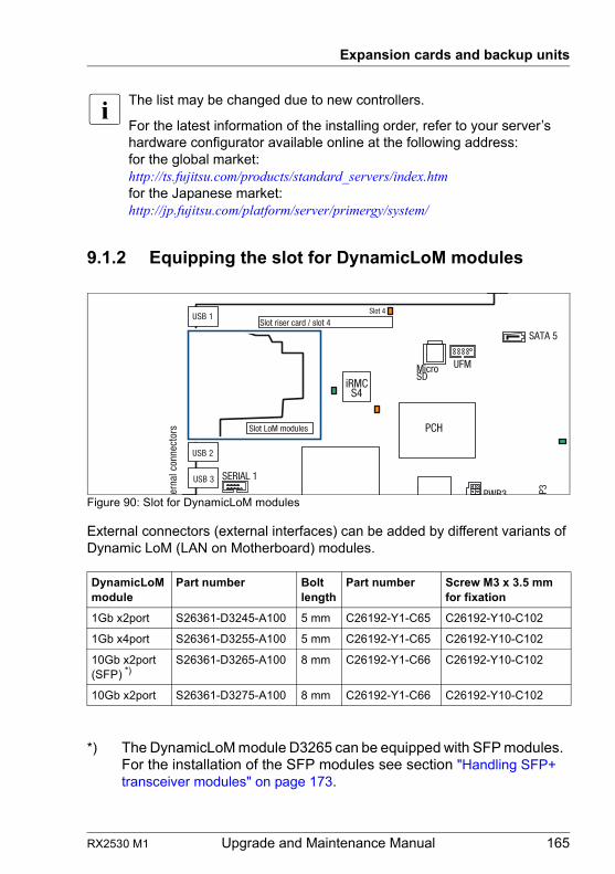
RX2530 M1 Upgrade and Maintenance Manual 165
Expansion cards and backup units
I The list may be changed due to new controllers.
For the latest information of the installing order, refer to your server’s hardware configurator available online at the following address:for the global market:http://ts.fujitsu.com/products/standard_servers/index.htm for the Japanese market:http://jp.fujitsu.com/platform/server/primergy/system/
9.1.2 Equipping the slot for DynamicLoM modules
Figure 90: Slot for DynamicLoM modules
External connectors (external interfaces) can be added by different variants of Dynamic LoM (LAN on Motherboard) modules.
DynamicLoM module
Part number Bolt length
Part number Screw M3 x 3.5 mm for fixation
1Gb x2port S26361-D3245-A100 5 mm C26192-Y1-C65 C26192-Y10-C102
1Gb x4port S26361-D3255-A100 5 mm C26192-Y1-C65 C26192-Y10-C102
10Gb x2port (SFP) *)
S26361-D3265-A100 8 mm C26192-Y1-C66 C26192-Y10-C102
10Gb x2port S26361-D3275-A100 8 mm C26192-Y1-C66 C26192-Y10-C102
*) The DynamicLoM module D3265 can be equipped with SFP modules. For the installation of the SFP modules see section "Handling SFP+ transceiver modules" on page 173.
iRMCS4
tern
al c
onne
ctor
s
USB 2
USB 3
PCH
P3
USB 1Slot riser card / slot 4
UFM
SERIAL 1
Slot 4
PWR3
MicroSD
SATA 5
Slot LoM modules
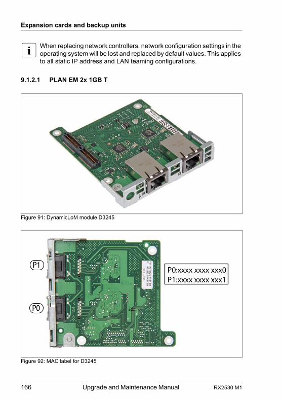
166 Upgrade and Maintenance Manual RX2530 M1
Expansion cards and backup units
I When replacing network controllers, network configuration settings in the operating system will be lost and replaced by default values. This applies to all static IP address and LAN teaming configurations.
9.1.2.1 PLAN EM 2x 1GB T
Figure 91: DynamicLoM module D3245
Figure 92: MAC label for D3245
P0:xxxx xxxx xxx0P1:xxxx xxxx xxx1
P1
P0
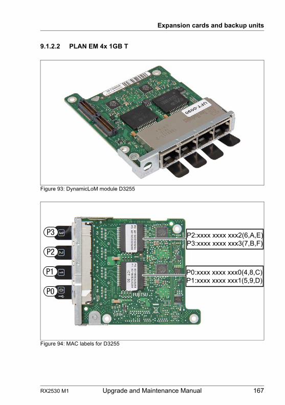
RX2530 M1 Upgrade and Maintenance Manual 167
Expansion cards and backup units
9.1.2.2 PLAN EM 4x 1GB T
Figure 93: DynamicLoM module D3255
Figure 94: MAC labels for D3255
P2:xxxx xxxx xxx2(6,A,E)P3:xxxx xxxx xxx3(7,B,F)
P0:xxxx xxxx xxx0(4,8,C)P1:xxxx xxxx xxx1(5,9,D)
P3
P1
P2
P0
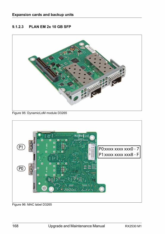
168 Upgrade and Maintenance Manual RX2530 M1
Expansion cards and backup units
9.1.2.3 PLAN EM 2x 10 GB SFP
Figure 95: DynamicLoM module D3265
Figure 96: MAC label D3265
P0:xxxx xxxx xxx0 - 7P1:xxxx xxxx xxx8 - F
P1
P0
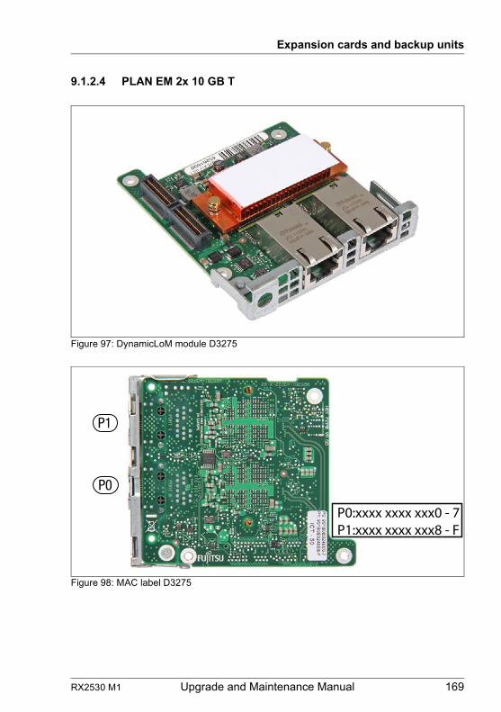
RX2530 M1 Upgrade and Maintenance Manual 169
Expansion cards and backup units
9.1.2.4 PLAN EM 2x 10 GB T
Figure 97: DynamicLoM module D3275
Figure 98: MAC label D3275
P0:xxxx xxxx xxx0 - 7P1:xxxx xxxx xxx8 - F
P1
P0
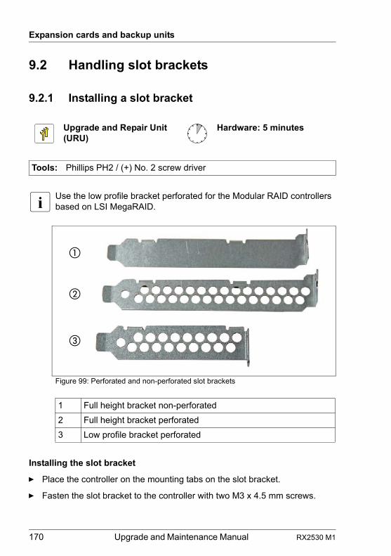
170 Upgrade and Maintenance Manual RX2530 M1
Expansion cards and backup units
9.2 Handling slot brackets
9.2.1 Installing a slot bracket
I Use the low profile bracket perforated for the Modular RAID controllers based on LSI MegaRAID.
Figure 99: Perforated and non-perforated slot brackets
Installing the slot bracket
Ê Place the controller on the mounting tabs on the slot bracket.
Ê Fasten the slot bracket to the controller with two M3 x 4.5 mm screws.
Upgrade and Repair Unit(URU)
Hardware: 5 minutes
Tools: Phillips PH2 / (+) No. 2 screw driver
1 Full height bracket non-perforated
2 Full height bracket perforated
3 Low profile bracket perforated
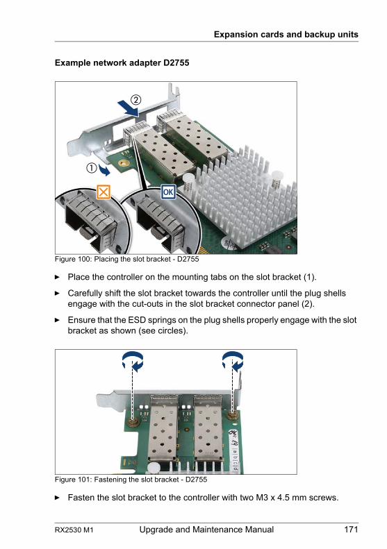
RX2530 M1 Upgrade and Maintenance Manual 171
Expansion cards and backup units
Example network adapter D2755
Figure 100: Placing the slot bracket - D2755
Ê Place the controller on the mounting tabs on the slot bracket (1).
Ê Carefully shift the slot bracket towards the controller until the plug shells engage with the cut-outs in the slot bracket connector panel (2).
Ê Ensure that the ESD springs on the plug shells properly engage with the slot bracket as shown (see circles).
Figure 101: Fastening the slot bracket - D2755
Ê Fasten the slot bracket to the controller with two M3 x 4.5 mm screws.
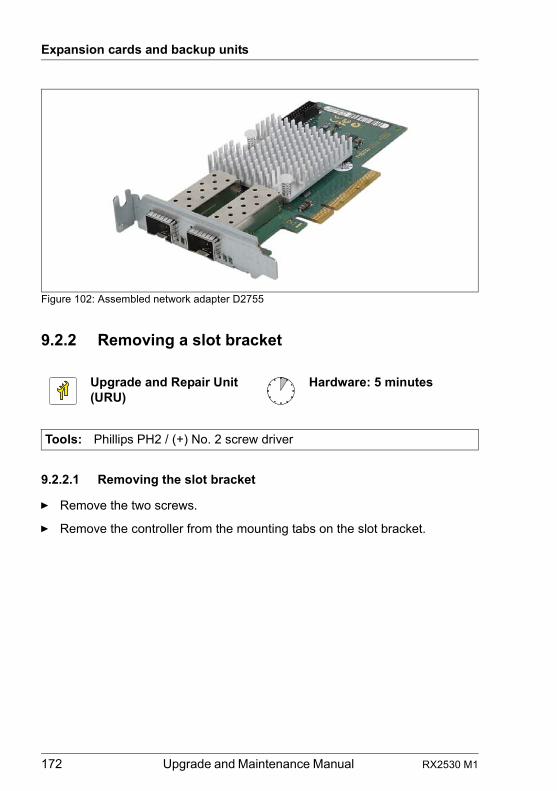
172 Upgrade and Maintenance Manual RX2530 M1
Expansion cards and backup units
Figure 102: Assembled network adapter D2755
9.2.2 Removing a slot bracket
9.2.2.1 Removing the slot bracket
Ê Remove the two screws.
Ê Remove the controller from the mounting tabs on the slot bracket.
Upgrade and Repair Unit(URU)
Hardware: 5 minutes
Tools: Phillips PH2 / (+) No. 2 screw driver
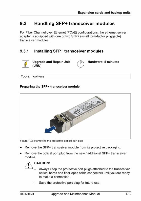
RX2530 M1 Upgrade and Maintenance Manual 173
Expansion cards and backup units
9.3 Handling SFP+ transceiver modules
For Fiber Channel over Ethernet (FCoE) configurations, the ethernet server adapter is equipped with one or two SFP+ (small form-factor pluggable) transceiver modules.
9.3.1 Installing SFP+ transceiver modules
Preparing the SFP+ transceiver module
Figure 103: Removing the protective optical port plug
Ê Remove the SFP+ transceiver module from its protective packaging.
Ê Remove the optical port plug from the new / additional SFP+ transceiver module.
V CAUTION!
– Always keep the protective port plugs attached to the transceiver optical bores and fiber-optic cable connectors until you are ready to make a connection.
– Save the protective port plug for future use.
Upgrade and Repair Unit(URU)
Hardware: 5 minutes
Tools: tool-less
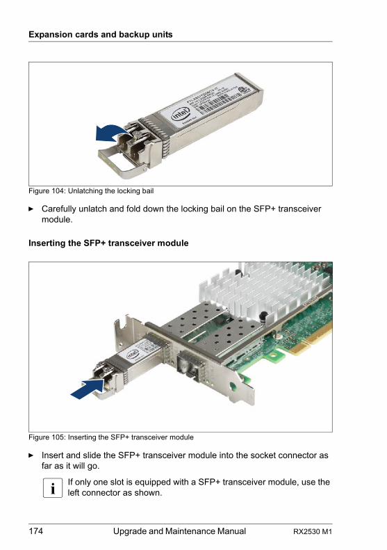
174 Upgrade and Maintenance Manual RX2530 M1
Expansion cards and backup units
Figure 104: Unlatching the locking bail
Ê Carefully unlatch and fold down the locking bail on the SFP+ transceiver module.
Inserting the SFP+ transceiver module
Figure 105: Inserting the SFP+ transceiver module
Ê Insert and slide the SFP+ transceiver module into the socket connector as far as it will go.
I If only one slot is equipped with a SFP+ transceiver module, use the left connector as shown.
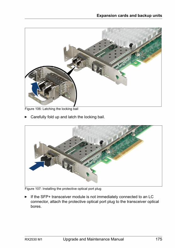
RX2530 M1 Upgrade and Maintenance Manual 175
Expansion cards and backup units
Figure 106: Latching the locking bail
Ê Carefully fold up and latch the locking bail.
Figure 107: Installing the protective optical port plug
Ê If the SFP+ transceiver module is not immediately connected to an LC connector, attach the protective optical port plug to the transceiver optical bores.
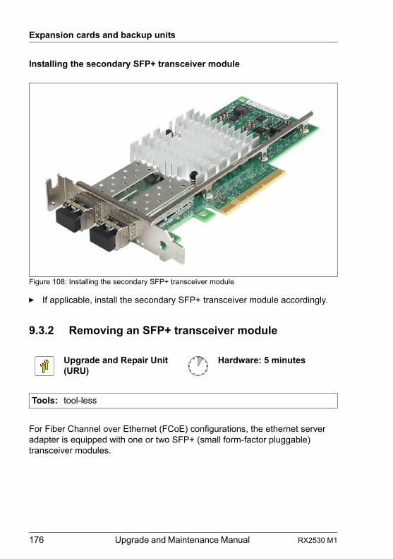
176 Upgrade and Maintenance Manual RX2530 M1
Expansion cards and backup units
Installing the secondary SFP+ transceiver module
Figure 108: Installing the secondary SFP+ transceiver module
Ê If applicable, install the secondary SFP+ transceiver module accordingly.
9.3.2 Removing an SFP+ transceiver module
For Fiber Channel over Ethernet (FCoE) configurations, the ethernet server adapter is equipped with one or two SFP+ (small form-factor pluggable) transceiver modules.
Upgrade and Repair Unit(URU)
Hardware: 5 minutes
Tools: tool-less
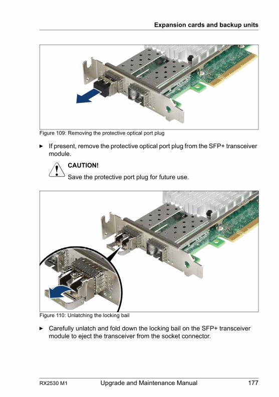
RX2530 M1 Upgrade and Maintenance Manual 177
Expansion cards and backup units
Figure 109: Removing the protective optical port plug
Ê If present, remove the protective optical port plug from the SFP+ transceiver module.
V CAUTION!
Save the protective port plug for future use.
Figure 110: Unlatching the locking bail
Ê Carefully unlatch and fold down the locking bail on the SFP+ transceiver module to eject the transceiver from the socket connector.
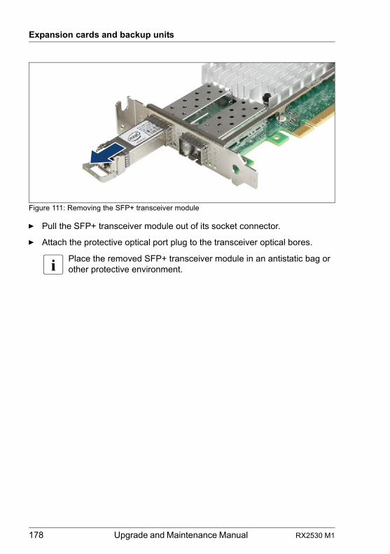
178 Upgrade and Maintenance Manual RX2530 M1
Expansion cards and backup units
Figure 111: Removing the SFP+ transceiver module
Ê Pull the SFP+ transceiver module out of its socket connector.
Ê Attach the protective optical port plug to the transceiver optical bores.
I Place the removed SFP+ transceiver module in an antistatic bag or other protective environment.
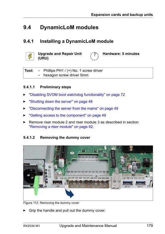
RX2530 M1 Upgrade and Maintenance Manual 179
Expansion cards and backup units
9.4 DynamicLoM modules
9.4.1 Installing a DynamicLoM module
9.4.1.1 Preliminary steps
Ê "Disabling SVOM boot watchdog functionality" on page 72
Ê "Shutting down the server" on page 48
Ê "Disconnecting the server from the mains" on page 49
Ê "Getting access to the component" on page 49
Ê Remove riser module 2 and riser module 3 as described in section "Removing a riser module" on page 62.
9.4.1.2 Removing the dummy cover
Figure 112: Removing the dummy cover
Ê Grip the handle and pull out the dummy cover.
Upgrade and Repair Unit(URU)
Hardware: 5 minutes
Tool: – Phillips PH1 / (+) No. 1 screw driver– hexagon screw driver 5mm
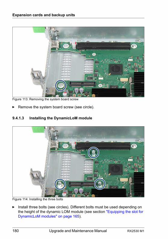
180 Upgrade and Maintenance Manual RX2530 M1
Expansion cards and backup units
Figure 113: Removing the system board screw
Ê Remove the system board screw (see circle).
9.4.1.3 Installing the DynamicLoM module
Figure 114: Installing the three bolts
Ê Install three bolts (see circles). Different bolts must be used depending on the height of the dynamic LOM module (see section "Equipping the slot for DynamicLoM modules" on page 165).
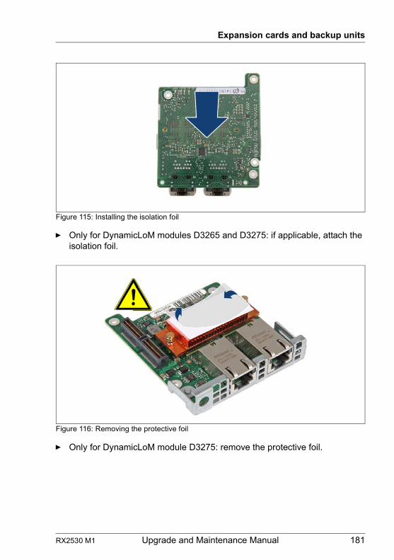
RX2530 M1 Upgrade and Maintenance Manual 181
Expansion cards and backup units
Figure 115: Installing the isolation foil
Ê Only for DynamicLoM modules D3265 and D3275: if applicable, attach the isolation foil.
Figure 116: Removing the protective foil
Ê Only for DynamicLoM module D3275: remove the protective foil.
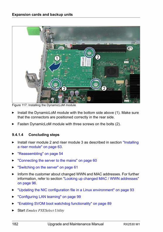
182 Upgrade and Maintenance Manual RX2530 M1
Expansion cards and backup units
Figure 117: Installing the DynamicLoM module
Ê Install the DynamicLoM module with the bottom side above (1). Make sure that the connectors are positioned correctly in the rear side.
Ê Fasten DynamicLoM module with three screws on the bolts (2).
9.4.1.4 Concluding steps
Ê Install riser module 2 and riser module 3 as described in section "Installing a riser module" on page 63.
Ê "Reassembling" on page 54
Ê "Connecting the server to the mains" on page 60
Ê "Switching on the server" on page 61
Ê Inform the customer about changed WWN and MAC addresses. For further information, refer to section "Looking up changed MAC / WWN addresses" on page 96.
Ê "Updating the NIC configuration file in a Linux environment" on page 93
Ê "Configuring LAN teaming" on page 99
Ê "Enabling SVOM boot watchdog functionality" on page 89
Ê Start Emulex PXESelect Utility
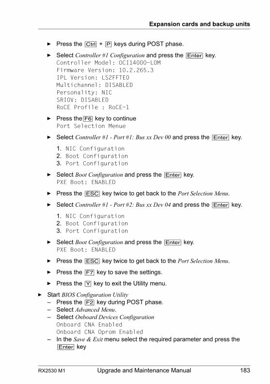
RX2530 M1 Upgrade and Maintenance Manual 183
Expansion cards and backup units
Ê Press the [Ctrl] + [P] keys during POST phase.
Ê Select Controller #1 Configuration and press the [Enter] key.Controller Model: OCI14000-LOMFirmware Version: 10.2.265.3IPL Version: LS2FFTE0Multichannel: DISABLEDPersonality: NICSRIOV: DISABLEDRoCE Profile : RoCE-1
Ê Press the[F6] key to continuePort Selection Menue
Ê Select Controller #1 - Port #1: Bus xx Dev 00 and press the [Enter] key.
1. NIC Configuration2. Boot Configuration3. Port Configuration
Ê Select Boot Configuration and press the [Enter] key.PXE Boot: ENABLED
Ê Press the [ESC] key twice to get back to the Port Selection Menu.
Ê Select Controller #1 - Port #2: Bus xx Dev 04 and press the [Enter] key.
1. NIC Configuration2. Boot Configuration3. Port Configuration
Ê Select Boot Configuration and press the [Enter] key.PXE Boot: ENABLED
Ê Press the [ESC] key twice to get back to the Port Selection Menu.
Ê Press the [F7] key to save the settings.
Ê Press the [Y] key to exit the Utility menu.
Ê Start BIOS Configuration Utility– Press the [F2] key during POST phase.– Select Advanced Menu.– Select Onboard Devices Configuration
Onboard CNA EnabledOnboard CNA Oprom Enabled
– In the Save & Exit menu select the required parameter and press the [Enter] key
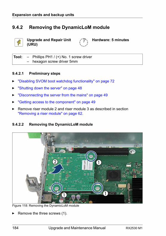
184 Upgrade and Maintenance Manual RX2530 M1
Expansion cards and backup units
9.4.2 Removing the DynamicLoM module
9.4.2.1 Preliminary steps
Ê "Disabling SVOM boot watchdog functionality" on page 72
Ê "Shutting down the server" on page 48
Ê "Disconnecting the server from the mains" on page 49
Ê "Getting access to the component" on page 49
Ê Remove riser module 2 and riser module 3 as described in section "Removing a riser module" on page 62.
9.4.2.2 Removing the DynamicLoM module
Figure 118: Removing the DynamicLoM module
Ê Remove the three screws (1).
Upgrade and Repair Unit(URU)
Hardware: 5 minutes
Tool: – Phillips PH1 / (+) No. 1 screw driver– hexagon screw driver 5mm
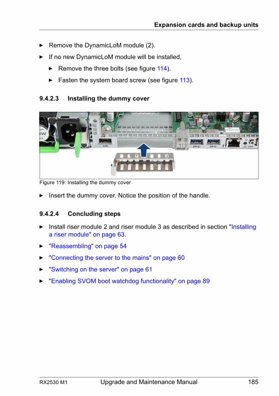
RX2530 M1 Upgrade and Maintenance Manual 185
Expansion cards and backup units
Ê Remove the DynamicLoM module (2).
Ê If no new DynamicLoM module will be installed,
Ê Remove the three bolts (see figure 114).
Ê Fasten the system board screw (see figure 113).
9.4.2.3 Installing the dummy cover
Figure 119: Installing the dummy cover
Ê Insert the dummy cover. Notice the position of the handle.
9.4.2.4 Concluding steps
Ê Install riser module 2 and riser module 3 as described in section "Installing a riser module" on page 63.
Ê "Reassembling" on page 54
Ê "Connecting the server to the mains" on page 60
Ê "Switching on the server" on page 61
Ê "Enabling SVOM boot watchdog functionality" on page 89
186 Upgrade and Maintenance Manual RX2530 M1
Expansion cards and backup units
9.4.3 Replacing the DynamicLoM module
9.4.3.1 Preliminary steps
Ê "Disabling SVOM boot watchdog functionality" on page 72
Ê "Shutting down the server" on page 48
Ê "Disconnecting the server from the mains" on page 49
Ê "Getting access to the component" on page 49
Ê Remove riser module 2 and riser module 3 as described in section "Removing a riser module" on page 62.
9.4.3.2 Removing the defective DynamicLoM module
Ê Remove the DynamicLoM module as described in section "Removing the DynamicLoM module" on page 184. The three bolts remain installed.
9.4.3.3 Installing the new DynamicLoM module
Ê Install the DynamicLoM module as described in section "Installing the DynamicLoM module" on page 180.
9.4.3.4 Concluding steps
Ê Install riser module 2 and riser module 3 as described in section "Installing a riser module" on page 63.
Ê "Reassembling" on page 54
Ê "Connecting the server to the mains" on page 60
Ê "Switching on the server" on page 61
Upgrade and Repair Unit(URU)
Hardware: 10 minutes
Tool: – Phillips PH1 / (+) No. 1 screw driver– hexagon screw driver 5mm
RX2530 M1 Upgrade and Maintenance Manual 187
Expansion cards and backup units
Ê Inform the customer about changed WWN and MAC addresses. For further information, refer to section "Looking up changed MAC / WWN addresses" on page 96.
Ê "Updating the NIC configuration file in a Linux environment" on page 93
Ê "Configuring LAN teaming" on page 99
Ê "Enabling SVOM boot watchdog functionality" on page 89
Ê Start Emulex PXESelect Utility
Ê Press the [Ctrl] + [P] keys during POST phase.
Ê Select Controller #1 Configuration and press the [Enter] key.Controller Model: OCI14000-LOMFirmware Version: 10.2.265.3IPL Version: LS2FFTE0Multichannel: DISABLEDPersonality: NICSRIOV: DISABLEDRoCE Profile : RoCE-1
Ê Press the[F6] key to continuePort Selection Menue
Ê Select Controller #1 - Port #1: Bus xx Dev 00 and press the [Enter] key.
1. NIC Configuration2. Boot Configuration3. Port Configuration
Ê Select Boot Configuration and press the [Enter] key.PXE Boot: ENABLED
Ê Press the [ESC] key twice to get back to the Port Selection Menu.
Ê Select Controller #1 - Port #2: Bus xx Dev 04 and press the [Enter] key.
1. NIC Configuration2. Boot Configuration3. Port Configuration
Ê Select Boot Configuration and press the [Enter] key.PXE Boot: ENABLED
Ê Press the [ESC] key twice to get back to the Port Selection Menu.
Ê Press the [F7] key to save the settings.
188 Upgrade and Maintenance Manual RX2530 M1
Expansion cards and backup units
Ê Press the [Y] key to exit the Utility menu.
Ê Start BIOS Configuration Utility
– Press the [F2] key during POST phase.– Select Advanced Menu.– Select Onboard Devices Configuration
Onboard CNA EnabledOnboard CNA Oprom Enabled
– In the Save & Exit menu select the required parameter and press the [Enter] key
Ê Reconfigure your network settings in the operation system according to the original configuration of the replaced controller (expansion card or onboard).
Ê Configuration of network settings should be performed by the customer.
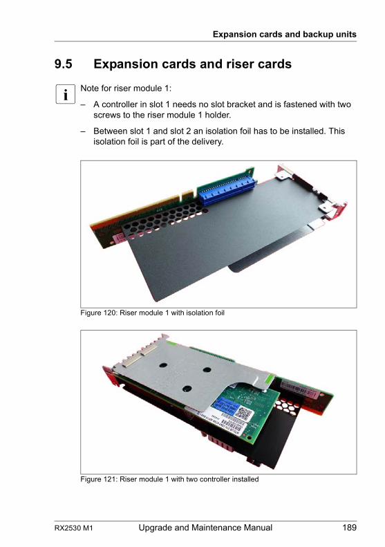
RX2530 M1 Upgrade and Maintenance Manual 189
Expansion cards and backup units
9.5 Expansion cards and riser cards
I Note for riser module 1:
– A controller in slot 1 needs no slot bracket and is fastened with two screws to the riser module 1 holder.
– Between slot 1 and slot 2 an isolation foil has to be installed. This isolation foil is part of the delivery.
Figure 120: Riser module 1 with isolation foil
Figure 121: Riser module 1 with two controller installed
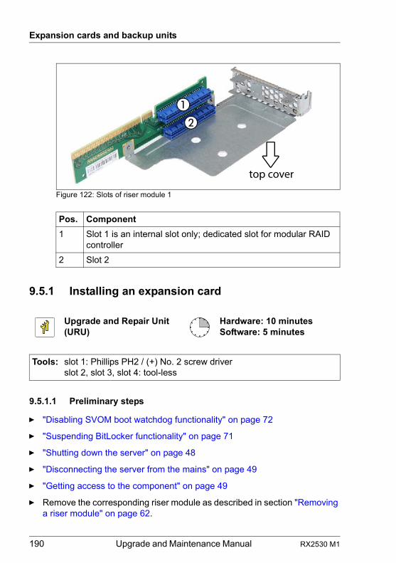
190 Upgrade and Maintenance Manual RX2530 M1
Expansion cards and backup units
Figure 122: Slots of riser module 1
9.5.1 Installing an expansion card
9.5.1.1 Preliminary steps
Ê "Disabling SVOM boot watchdog functionality" on page 72
Ê "Suspending BitLocker functionality" on page 71
Ê "Shutting down the server" on page 48
Ê "Disconnecting the server from the mains" on page 49
Ê "Getting access to the component" on page 49
Ê Remove the corresponding riser module as described in section "Removing a riser module" on page 62.
Pos. Component
1 Slot 1 is an internal slot only; dedicated slot for modular RAID controller
2 Slot 2
Upgrade and Repair Unit(URU)
Hardware: 10 minutesSoftware: 5 minutes
Tools: slot 1: Phillips PH2 / (+) No. 2 screw driverslot 2, slot 3, slot 4: tool-less
top cover
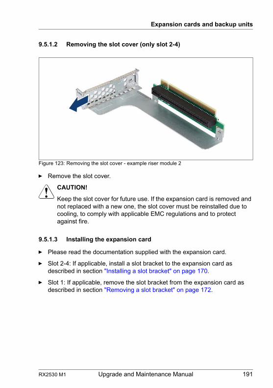
RX2530 M1 Upgrade and Maintenance Manual 191
Expansion cards and backup units
9.5.1.2 Removing the slot cover (only slot 2-4)
Figure 123: Removing the slot cover - example riser module 2
Ê Remove the slot cover.
V CAUTION!
Keep the slot cover for future use. If the expansion card is removed and not replaced with a new one, the slot cover must be reinstalled due to cooling, to comply with applicable EMC regulations and to protect against fire.
9.5.1.3 Installing the expansion card
Ê Please read the documentation supplied with the expansion card.
Ê Slot 2-4: If applicable, install a slot bracket to the expansion card as described in section "Installing a slot bracket" on page 170.
Ê Slot 1: If applicable, remove the slot bracket from the expansion card as described in section "Removing a slot bracket" on page 172.
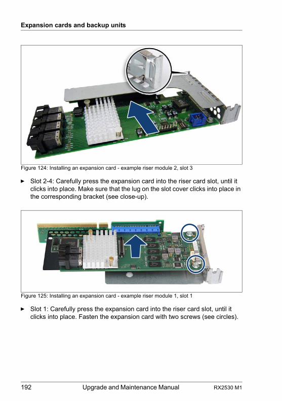
192 Upgrade and Maintenance Manual RX2530 M1
Expansion cards and backup units
Figure 124: Installing an expansion card - example riser module 2, slot 3
Ê Slot 2-4: Carefully press the expansion card into the riser card slot, until it clicks into place. Make sure that the lug on the slot cover clicks into place in the corresponding bracket (see close-up).
Figure 125: Installing an expansion card - example riser module 1, slot 1
Ê Slot 1: Carefully press the expansion card into the riser card slot, until it clicks into place. Fasten the expansion card with two screws (see circles).
RX2530 M1 Upgrade and Maintenance Manual 193
Expansion cards and backup units
9.5.1.4 Concluding steps
Ê Install the corresponding riser module as described in section "Installing a riser module" on page 63.
Ê "Reassembling" on page 54
Ê "Connecting the server to the mains" on page 60
Ê "Updating RAID controller firmware" on page 82
Ê "Enabling Option ROM scan" on page 83
Ê "Enabling SVOM boot watchdog functionality" on page 89
Ê "Switching on the server" on page 61
Ê "Resuming BitLocker functionality" on page 95
9.5.2 Removing an expansion card
9.5.2.1 Preliminary steps
Ê "Suspending BitLocker functionality" on page 71
Ê "Shutting down the server" on page 48
Ê "Disconnecting the server from the mains" on page 49
Ê "Getting access to the component" on page 49
Ê Remove the corresponding riser module as described in section "Removing a riser module" on page 62.
Upgrade and Repair Unit(URU)
Hardware: 5 minutes
Tools: slot 1: Phillips PH2 / (+) No. 2 screw driverslot 2, slot 3, slot 4: tool-less
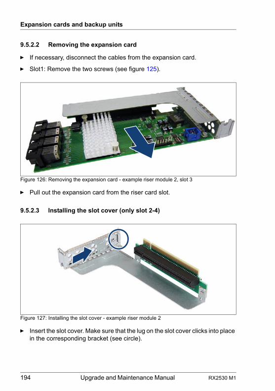
194 Upgrade and Maintenance Manual RX2530 M1
Expansion cards and backup units
9.5.2.2 Removing the expansion card
Ê If necessary, disconnect the cables from the expansion card.
Ê Slot1: Remove the two screws (see figure 125).
Figure 126: Removing the expansion card - example riser module 2, slot 3
Ê Pull out the expansion card from the riser card slot.
9.5.2.3 Installing the slot cover (only slot 2-4)
Figure 127: Installing the slot cover - example riser module 2
Ê Insert the slot cover. Make sure that the lug on the slot cover clicks into place in the corresponding bracket (see circle).
RX2530 M1 Upgrade and Maintenance Manual 195
Expansion cards and backup units
9.5.2.4 Concluding steps
Ê Install the corresponding riser module as described in section "Installing a riser module" on page 63.
Ê "Reassembling" on page 54
Ê "Connecting the server to the mains" on page 60
Ê "Switching on the server" on page 61
Ê "Resuming BitLocker functionality" on page 95
9.5.3 Replacing an expansion card
Note on network settings recovery
I When replacing network controllers or the system board, network configuration settings in the operating system will be lost and replaced by default values. This applies to all static IP address and LAN teaming configurations.
Ensure to note down your current network settings before replacing a network controller or the system board.
9.5.3.1 Preliminary steps
Ê "Locating the defective server" on page 45
Ê If applicable, ensure to note down your current network settings in the operating system.
Ê "Disabling SVOM boot watchdog functionality" on page 72
Ê "Suspending BitLocker functionality" on page 71
Ê "Shutting down the server" on page 48
Upgrade and Repair Unit(URU)
Hardware: 10 minutesSoftware: 5 minutes
Tools: slot 1: Phillips PH2 / (+) No. 2 screw driverslot 2, slot 3, slot 4: tool-less
196 Upgrade and Maintenance Manual RX2530 M1
Expansion cards and backup units
Ê "Disconnecting the server from the mains" on page 49
Ê "Getting access to the component" on page 49
Ê "Locating the defective component" on page 47
Ê Remove the corresponding riser module as described in section "Handling riser modules" on page 62.
9.5.3.2 Removing the defective expansion card
Ê Remove the expansion card as described in section "Removing the expansion card" on page 194.
Ê If the slot bracket on the defective expansion card is to be reused, remove it from the expansion card as described in section "Removing a slot bracket" on page 172.
9.5.3.3 Installing the new expansion card
Ê If applicable, install the slot bracket as described in section "Installing a slot bracket" on page 170.
Ê Install the expansion card as described in section "Installing the expansion card" on page 191.
9.5.3.4 Concluding steps
Ê Install the corresponding riser module as described in section "Handling riser modules" on page 62.
Ê "Reassembling" on page 54
Ê "Connecting the server to the mains" on page 60
Ê "Enabling replaced components in the system BIOS" on page 90
Ê "Updating RAID controller firmware" on page 82
Ê "Enabling SVOM boot watchdog functionality" on page 89
Ê "Switching on the server" on page 61
Ê "Resuming BitLocker functionality" on page 95
Ê After replacing a network controller in a server running Linux OS, "Updating the NIC configuration file in a Linux environment" on page 93.
RX2530 M1 Upgrade and Maintenance Manual 197
Expansion cards and backup units
Ê If applicable, reconfigure your network settings in the operation system according to the original configuration of the replaced controller (expansion card or onboard).
I Configuration of network settings should be performed by the customer. For further information, please refer to section "Note on network settings recovery" on page 195.
Ê If applicable, restore LAN teaming configurations, see "After replacing / upgrading LAN controllers" on page 99.
Ê Inform the customer about changed WWN and MAC addresses, see "Looking up changed MAC / WWN addresses" on page 96.
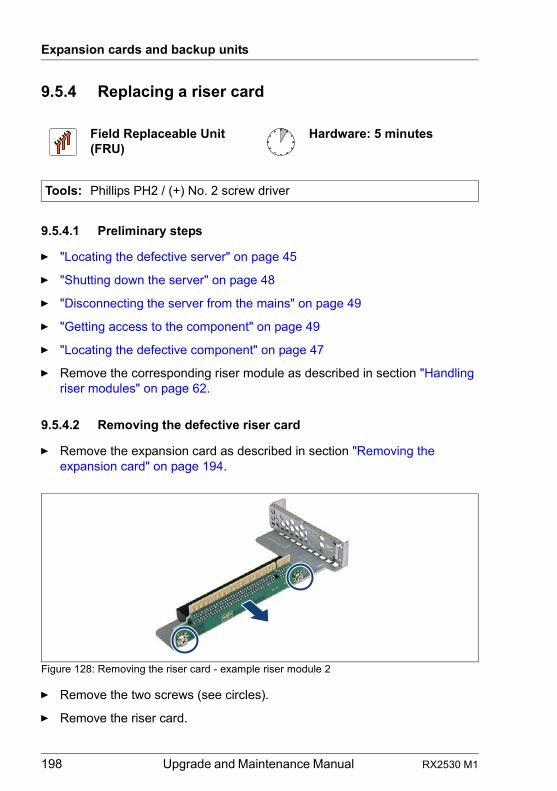
198 Upgrade and Maintenance Manual RX2530 M1
Expansion cards and backup units
9.5.4 Replacing a riser card
9.5.4.1 Preliminary steps
Ê "Locating the defective server" on page 45
Ê "Shutting down the server" on page 48
Ê "Disconnecting the server from the mains" on page 49
Ê "Getting access to the component" on page 49
Ê "Locating the defective component" on page 47
Ê Remove the corresponding riser module as described in section "Handling riser modules" on page 62.
9.5.4.2 Removing the defective riser card
Ê Remove the expansion card as described in section "Removing the expansion card" on page 194.
Figure 128: Removing the riser card - example riser module 2
Ê Remove the two screws (see circles).
Ê Remove the riser card.
Field Replaceable Unit(FRU)
Hardware: 5 minutes
Tools: Phillips PH2 / (+) No. 2 screw driver
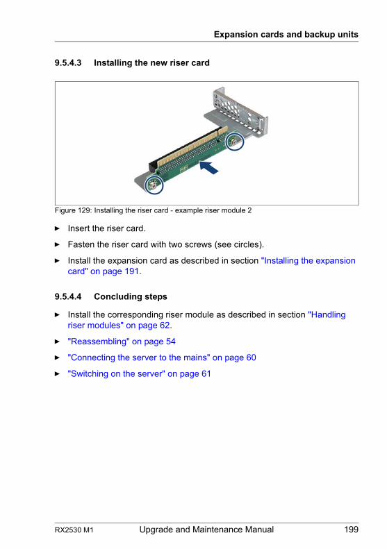
RX2530 M1 Upgrade and Maintenance Manual 199
Expansion cards and backup units
9.5.4.3 Installing the new riser card
Figure 129: Installing the riser card - example riser module 2
Ê Insert the riser card.
Ê Fasten the riser card with two screws (see circles).
Ê Install the expansion card as described in section "Installing the expansion card" on page 191.
9.5.4.4 Concluding steps
Ê Install the corresponding riser module as described in section "Handling riser modules" on page 62.
Ê "Reassembling" on page 54
Ê "Connecting the server to the mains" on page 60
Ê "Switching on the server" on page 61
200 Upgrade and Maintenance Manual RX2530 M1
Expansion cards and backup units
9.5.5 Replacing a TFM
Notes for variants of TFM
Depending on the RAID controller, different TFM kits are available.
9.5.5.1 Preliminary steps
Ê "Locating the defective server" on page 45
Ê "Shutting down the server" on page 48
Ê "Disconnecting the server from the mains" on page 49
Ê "Getting access to the component" on page 49
Ê "Locating the defective component" on page 47
9.5.5.2 Removing the defective TFM
Ê Remove the depending expansion card as described in section "Removing the expansion card" on page 194.
RAID controller TFM kit
PRAID EP400iS26361-D3216-Axx
TFM 4G (LSZ:03-25444-05)
PRAID EP420iS26361-D3216-Bxx
TFM 8G (LSZ:03-25444-01)
Upgrade and Repair Unit(URU)
Hardware: 10 minutes
Tools: Phillips PH1 / (+) No. 1 screw driver
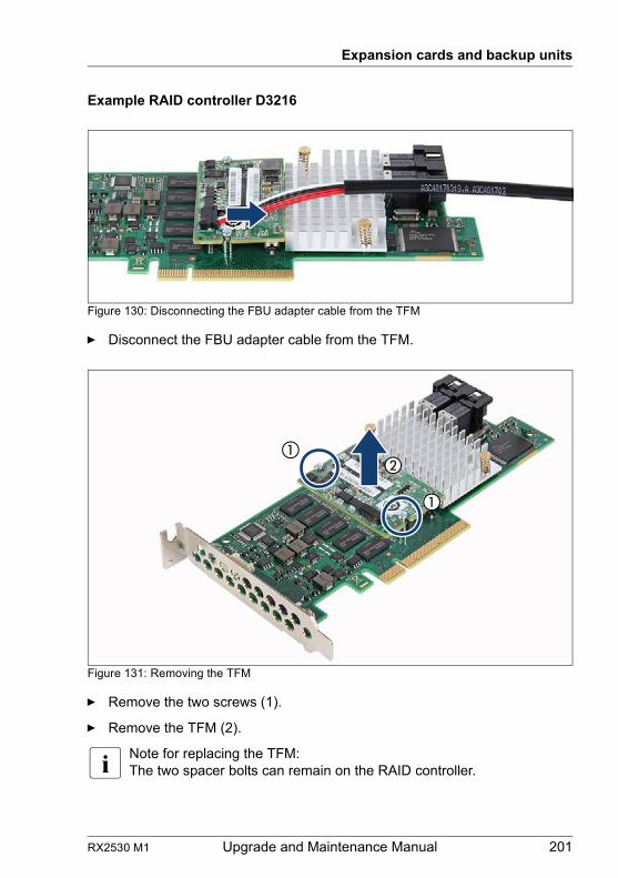
RX2530 M1 Upgrade and Maintenance Manual 201
Expansion cards and backup units
Example RAID controller D3216
Figure 130: Disconnecting the FBU adapter cable from the TFM
Ê Disconnect the FBU adapter cable from the TFM.
Figure 131: Removing the TFM
Ê Remove the two screws (1).
Ê Remove the TFM (2).
I Note for replacing the TFM:The two spacer bolts can remain on the RAID controller.
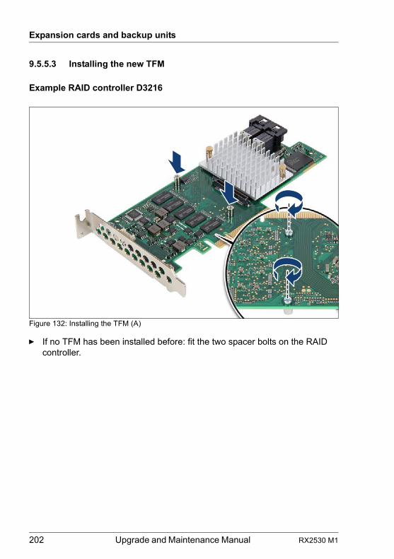
202 Upgrade and Maintenance Manual RX2530 M1
Expansion cards and backup units
9.5.5.3 Installing the new TFM
Example RAID controller D3216
Figure 132: Installing the TFM (A)
Ê If no TFM has been installed before: fit the two spacer bolts on the RAID controller.
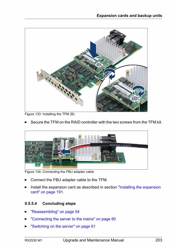
RX2530 M1 Upgrade and Maintenance Manual 203
Expansion cards and backup units
Figure 133: Installing the TFM (B)
Ê Secure the TFM on the RAID controller with the two screws from the TFM kit.
Figure 134: Connecting the FBU adapter cable
Ê Connect the FBU adapter cable to the TFM.
Ê Install the expansion card as described in section "Installing the expansion card" on page 191.
9.5.5.4 Concluding steps
Ê "Reassembling" on page 54
Ê "Connecting the server to the mains" on page 60
Ê "Switching on the server" on page 61
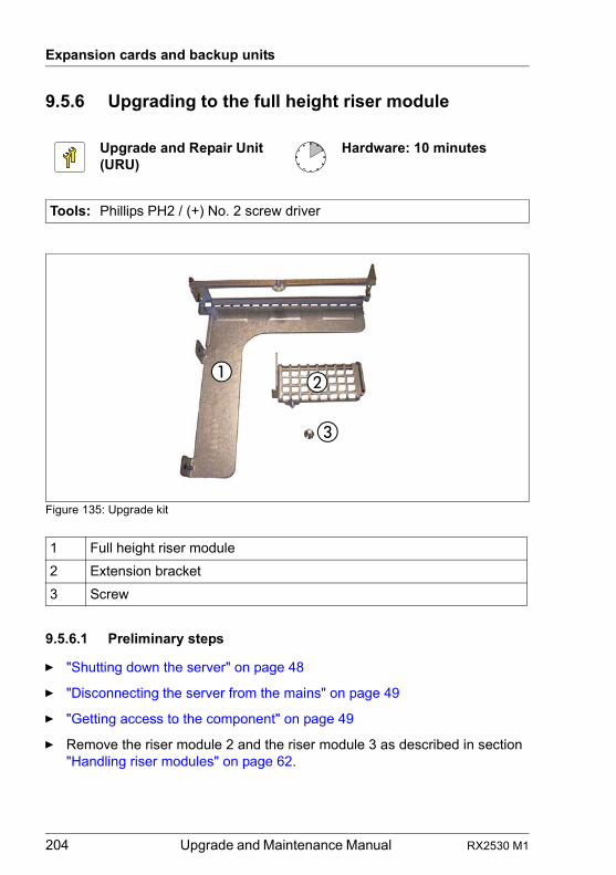
204 Upgrade and Maintenance Manual RX2530 M1
Expansion cards and backup units
9.5.6 Upgrading to the full height riser module
Figure 135: Upgrade kit
9.5.6.1 Preliminary steps
Ê "Shutting down the server" on page 48
Ê "Disconnecting the server from the mains" on page 49
Ê "Getting access to the component" on page 49
Ê Remove the riser module 2 and the riser module 3 as described in section "Handling riser modules" on page 62.
Upgrade and Repair Unit(URU)
Hardware: 10 minutes
Tools: Phillips PH2 / (+) No. 2 screw driver
1 Full height riser module
2 Extension bracket
3 Screw
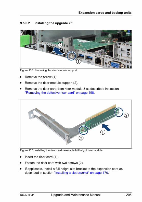
RX2530 M1 Upgrade and Maintenance Manual 205
Expansion cards and backup units
9.5.6.2 Installing the upgrade kit
Figure 136: Removing the riser module support
Ê Remove the screw (1).
Ê Remove the riser module support (2).
Ê Remove the riser card from riser module 3 as described in section "Removing the defective riser card" on page 198.
Figure 137: Installing the riser card - example full height riser module
Ê Insert the riser card (1).
Ê Fasten the riser card with two screws (2).
Ê If applicable, install a full height slot bracket to the expansion card as described in section "Installing a slot bracket" on page 170.
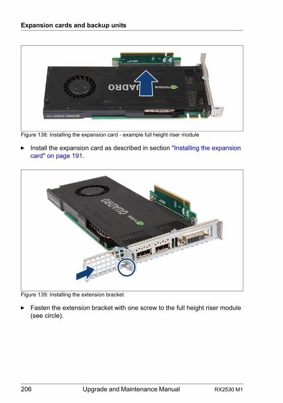
206 Upgrade and Maintenance Manual RX2530 M1
Expansion cards and backup units
Figure 138: Installing the expansion card - example full height riser module
Ê Install the expansion card as described in section "Installing the expansion card" on page 191.
Figure 139: Installing the extension bracket
Ê Fasten the extension bracket with one screw to the full height riser module (see circle).
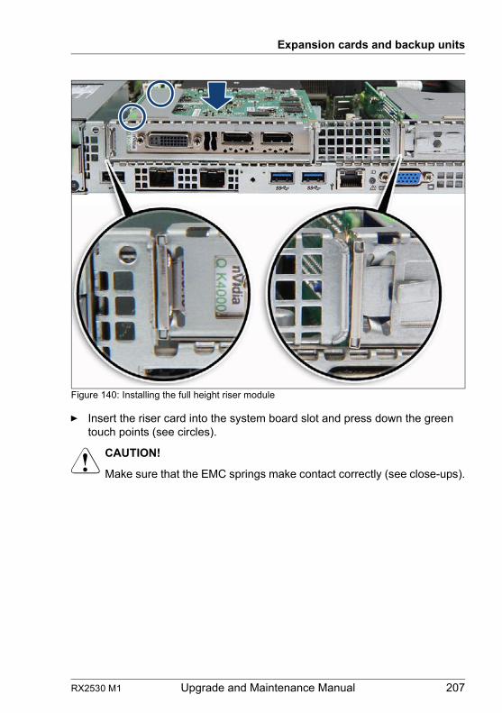
RX2530 M1 Upgrade and Maintenance Manual 207
Expansion cards and backup units
Figure 140: Installing the full height riser module
Ê Insert the riser card into the system board slot and press down the green touch points (see circles).
V CAUTION!
Make sure that the EMC springs make contact correctly (see close-ups).
208 Upgrade and Maintenance Manual RX2530 M1
Expansion cards and backup units
9.6 Flash Backup unit
The FBU backs up the memory contents of the RAID controller in the event of a power failure. You can install one FBU.
Depending on the chassis (3.5-inch HDD chassis or 2.5-inch HDD chassis) the installation in the FBU holder and the position for the FBU holder are different.
9.6.1 Installing an FBU in a 2.5-inch HDD chassis
9.6.1.1 Preliminary steps
Ê "Disabling SVOM boot watchdog functionality" on page 72
Ê "Shutting down the server" on page 48
Ê "Disconnecting the server from the mains" on page 49
Ê "Getting access to the component" on page 49
Upgrade and Repair Unit(URU)
Hardware: 15 minutes
Tools: Phillips PH1 / (+) No. 1 screw driver (for installing TFM)
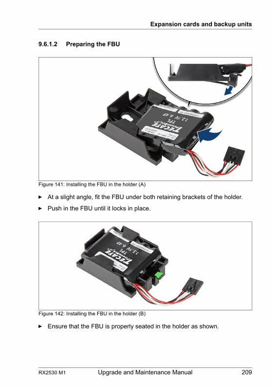
RX2530 M1 Upgrade and Maintenance Manual 209
Expansion cards and backup units
9.6.1.2 Preparing the FBU
Figure 141: Installing the FBU in the holder (A)
Ê At a slight angle, fit the FBU under both retaining brackets of the holder.
Ê Push in the FBU until it locks in place.
Figure 142: Installing the FBU in the holder (B)
Ê Ensure that the FBU is properly seated in the holder as shown.
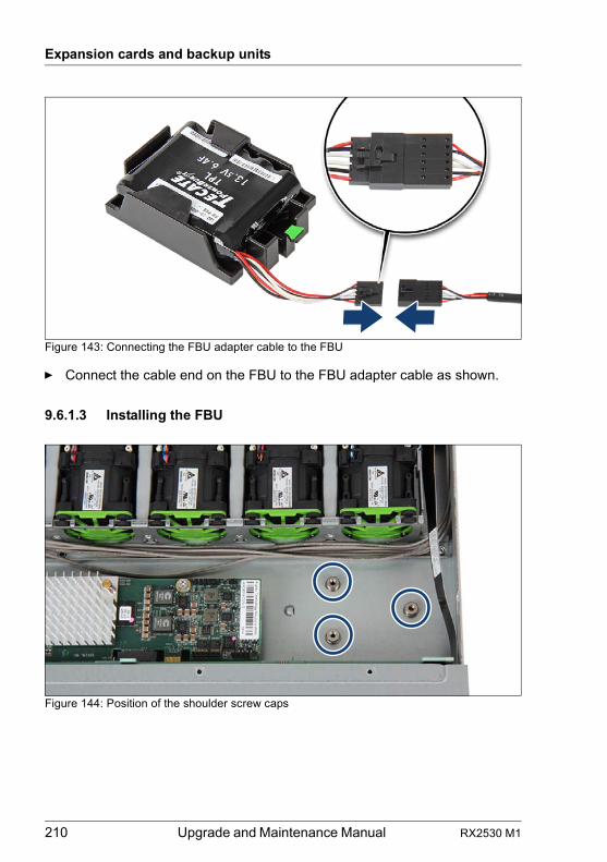
210 Upgrade and Maintenance Manual RX2530 M1
Expansion cards and backup units
Figure 143: Connecting the FBU adapter cable to the FBU
Ê Connect the cable end on the FBU to the FBU adapter cable as shown.
9.6.1.3 Installing the FBU
Figure 144: Position of the shoulder screw caps
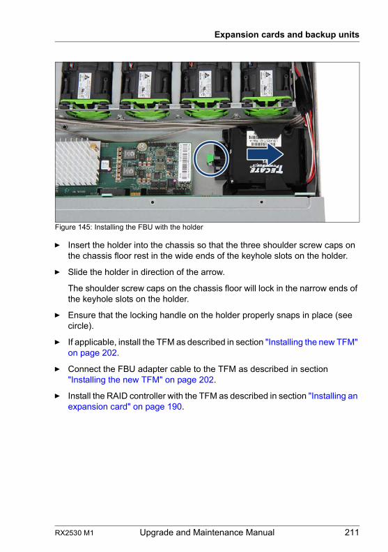
RX2530 M1 Upgrade and Maintenance Manual 211
Expansion cards and backup units
Figure 145: Installing the FBU with the holder
Ê Insert the holder into the chassis so that the three shoulder screw caps on the chassis floor rest in the wide ends of the keyhole slots on the holder.
Ê Slide the holder in direction of the arrow.
The shoulder screw caps on the chassis floor will lock in the narrow ends of the keyhole slots on the holder.
Ê Ensure that the locking handle on the holder properly snaps in place (see circle).
Ê If applicable, install the TFM as described in section "Installing the new TFM" on page 202.
Ê Connect the FBU adapter cable to the TFM as described in section "Installing the new TFM" on page 202.
Ê Install the RAID controller with the TFM as described in section "Installing an expansion card" on page 190.
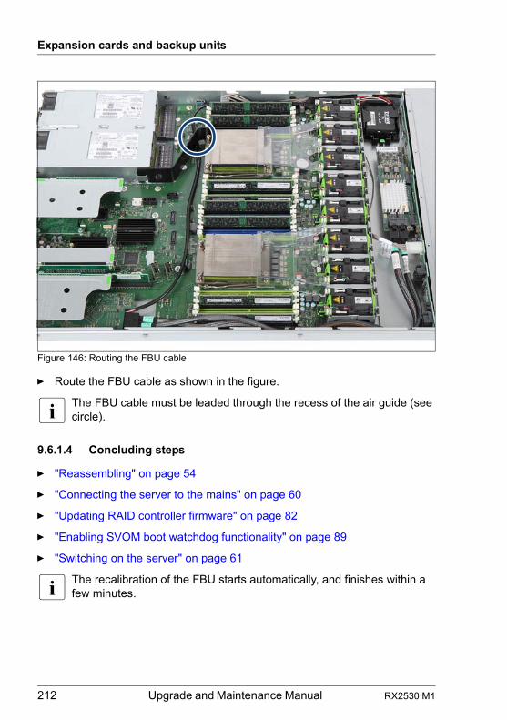
212 Upgrade and Maintenance Manual RX2530 M1
Expansion cards and backup units
Figure 146: Routing the FBU cable
Ê Route the FBU cable as shown in the figure.
I The FBU cable must be leaded through the recess of the air guide (see circle).
9.6.1.4 Concluding steps
Ê "Reassembling" on page 54
Ê "Connecting the server to the mains" on page 60
Ê "Updating RAID controller firmware" on page 82
Ê "Enabling SVOM boot watchdog functionality" on page 89
Ê "Switching on the server" on page 61
I The recalibration of the FBU starts automatically, and finishes within a few minutes.
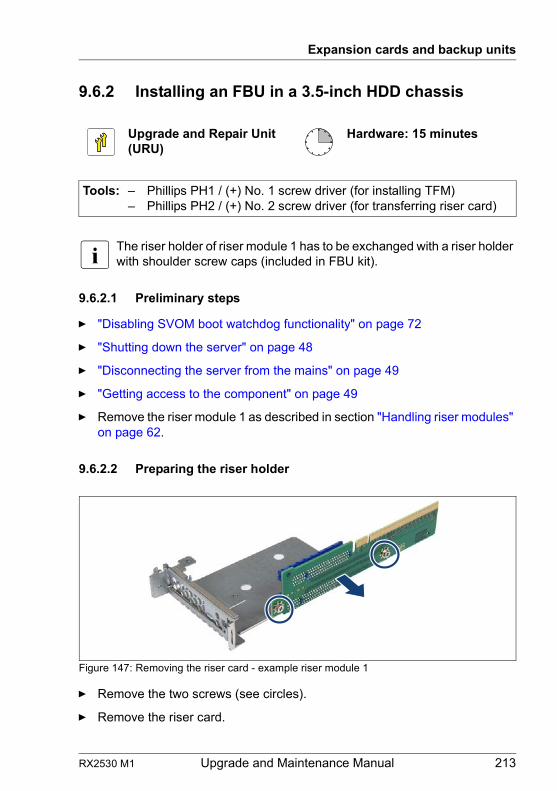
RX2530 M1 Upgrade and Maintenance Manual 213
Expansion cards and backup units
9.6.2 Installing an FBU in a 3.5-inch HDD chassis
I The riser holder of riser module 1 has to be exchanged with a riser holder with shoulder screw caps (included in FBU kit).
9.6.2.1 Preliminary steps
Ê "Disabling SVOM boot watchdog functionality" on page 72
Ê "Shutting down the server" on page 48
Ê "Disconnecting the server from the mains" on page 49
Ê "Getting access to the component" on page 49
Ê Remove the riser module 1 as described in section "Handling riser modules" on page 62.
9.6.2.2 Preparing the riser holder
Figure 147: Removing the riser card - example riser module 1
Ê Remove the two screws (see circles).
Ê Remove the riser card.
Upgrade and Repair Unit(URU)
Hardware: 15 minutes
Tools: – Phillips PH1 / (+) No. 1 screw driver (for installing TFM)– Phillips PH2 / (+) No. 2 screw driver (for transferring riser card)
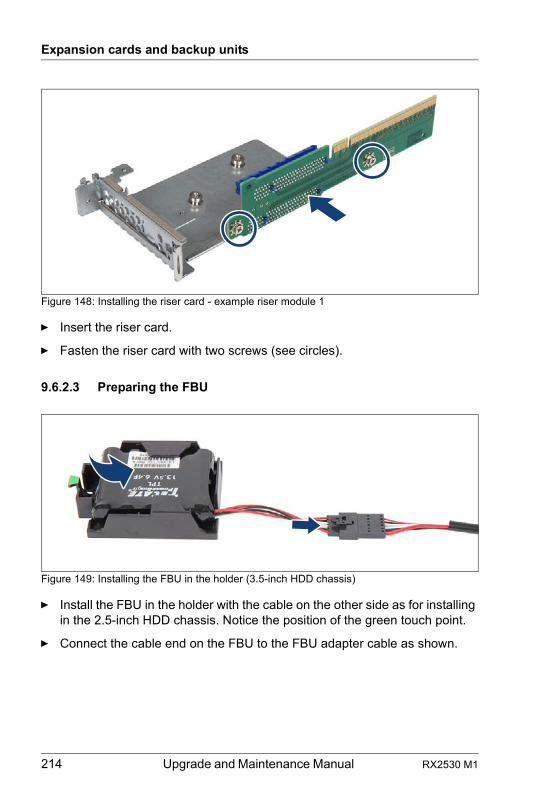
214 Upgrade and Maintenance Manual RX2530 M1
Expansion cards and backup units
Figure 148: Installing the riser card - example riser module 1
Ê Insert the riser card.
Ê Fasten the riser card with two screws (see circles).
9.6.2.3 Preparing the FBU
Figure 149: Installing the FBU in the holder (3.5-inch HDD chassis)
Ê Install the FBU in the holder with the cable on the other side as for installing in the 2.5-inch HDD chassis. Notice the position of the green touch point.
Ê Connect the cable end on the FBU to the FBU adapter cable as shown.
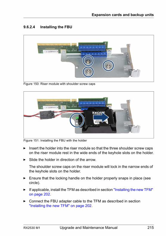
RX2530 M1 Upgrade and Maintenance Manual 215
Expansion cards and backup units
9.6.2.4 Installing the FBU
Figure 150: Riser module with shoulder screw caps
Figure 151: Installing the FBU with the holder
Ê Insert the holder into the riser module so that the three shoulder screw caps on the riser module rest in the wide ends of the keyhole slots on the holder.
Ê Slide the holder in direction of the arrow.
The shoulder screw caps on the riser module will lock in the narrow ends of the keyhole slots on the holder.
Ê Ensure that the locking handle on the holder properly snaps in place (see circle).
Ê If applicable, install the TFM as described in section "Installing the new TFM" on page 202.
Ê Connect the FBU adapter cable to the TFM as described in section "Installing the new TFM" on page 202.
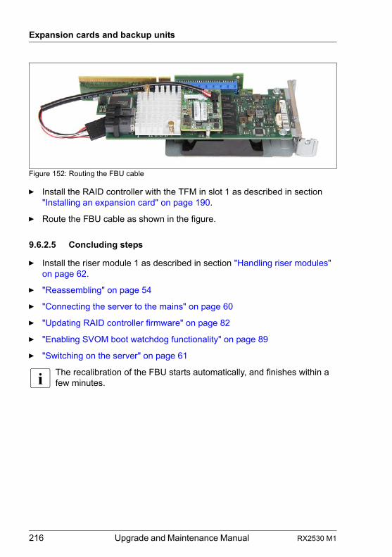
216 Upgrade and Maintenance Manual RX2530 M1
Expansion cards and backup units
Figure 152: Routing the FBU cable
Ê Install the RAID controller with the TFM in slot 1 as described in section "Installing an expansion card" on page 190.
Ê Route the FBU cable as shown in the figure.
9.6.2.5 Concluding steps
Ê Install the riser module 1 as described in section "Handling riser modules" on page 62.
Ê "Reassembling" on page 54
Ê "Connecting the server to the mains" on page 60
Ê "Updating RAID controller firmware" on page 82
Ê "Enabling SVOM boot watchdog functionality" on page 89
Ê "Switching on the server" on page 61
I The recalibration of the FBU starts automatically, and finishes within a few minutes.
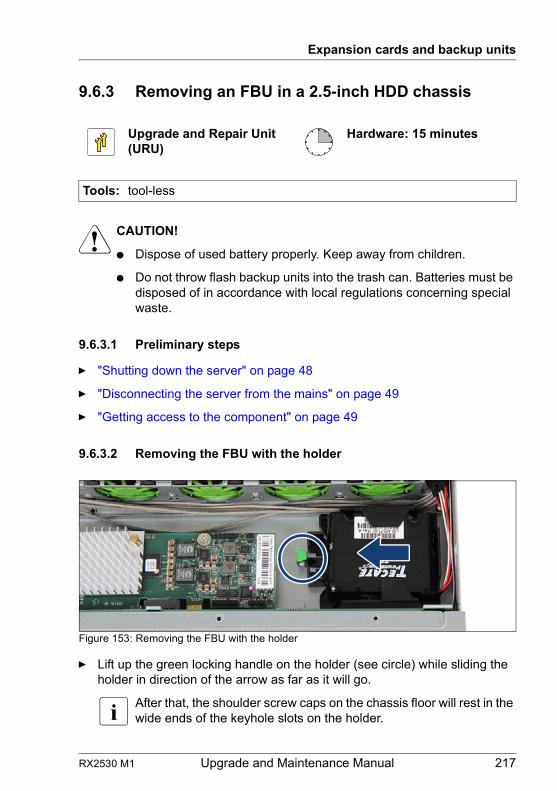
RX2530 M1 Upgrade and Maintenance Manual 217
Expansion cards and backup units
9.6.3 Removing an FBU in a 2.5-inch HDD chassis
V CAUTION!
● Dispose of used battery properly. Keep away from children.
● Do not throw flash backup units into the trash can. Batteries must be disposed of in accordance with local regulations concerning special waste.
9.6.3.1 Preliminary steps
Ê "Shutting down the server" on page 48
Ê "Disconnecting the server from the mains" on page 49
Ê "Getting access to the component" on page 49
9.6.3.2 Removing the FBU with the holder
Figure 153: Removing the FBU with the holder
Ê Lift up the green locking handle on the holder (see circle) while sliding the holder in direction of the arrow as far as it will go.
I After that, the shoulder screw caps on the chassis floor will rest in the wide ends of the keyhole slots on the holder.
Upgrade and Repair Unit(URU)
Hardware: 15 minutes
Tools: tool-less
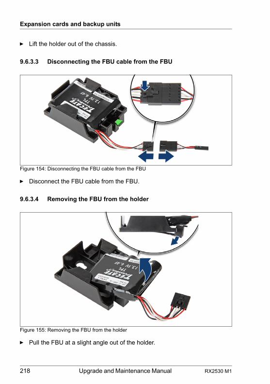
218 Upgrade and Maintenance Manual RX2530 M1
Expansion cards and backup units
Ê Lift the holder out of the chassis.
9.6.3.3 Disconnecting the FBU cable from the FBU
Figure 154: Disconnecting the FBU cable from the FBU
Ê Disconnect the FBU cable from the FBU.
9.6.3.4 Removing the FBU from the holder
Figure 155: Removing the FBU from the holder
Ê Pull the FBU at a slight angle out of the holder.
RX2530 M1 Upgrade and Maintenance Manual 219
Expansion cards and backup units
9.6.3.5 Concluding steps
Ê "Reassembling" on page 54
Ê "Connecting the server to the mains" on page 60
Ê "Switching on the server" on page 61
9.6.4 Removing an FBU in a 3.5-inch HDD chassis
V CAUTION!
● Dispose of used battery properly. Keep away from children.
● Do not throw flash backup units into the trash can. Batteries must be disposed of in accordance with local regulations concerning special waste.
9.6.4.1 Preliminary steps
Ê "Shutting down the server" on page 48
Ê "Disconnecting the server from the mains" on page 49
Ê "Getting access to the component" on page 49
Ê Remove the riser module 1 as described in section "Handling riser modules" on page 62.
Ê Remove the RAID controller in slot 1 as described in section "Removing an expansion card" on page 193.
Upgrade and Repair Unit(URU)
Hardware: 15 minutes
Tools: tool-less
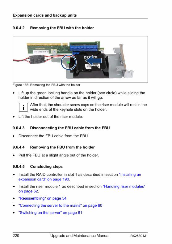
220 Upgrade and Maintenance Manual RX2530 M1
Expansion cards and backup units
9.6.4.2 Removing the FBU with the holder
Figure 156: Removing the FBU with the holder
Ê Lift up the green locking handle on the holder (see circle) while sliding the holder in direction of the arrow as far as it will go.
I After that, the shoulder screw caps on the riser module will rest in the wide ends of the keyhole slots on the holder.
Ê Lift the holder out of the riser module.
9.6.4.3 Disconnecting the FBU cable from the FBU
Ê Disconnect the FBU cable from the FBU.
9.6.4.4 Removing the FBU from the holder
Ê Pull the FBU at a slight angle out of the holder.
9.6.4.5 Concluding steps
Ê Install the RAID controller in slot 1 as described in section "Installing an expansion card" on page 190.
Ê Install the riser module 1 as described in section "Handling riser modules" on page 62.
Ê "Reassembling" on page 54
Ê "Connecting the server to the mains" on page 60
Ê "Switching on the server" on page 61
RX2530 M1 Upgrade and Maintenance Manual 221
Expansion cards and backup units
9.6.5 Replacing an FBU
V CAUTION!
● Dispose of used battery properly. Keep away from children.
● Do not throw flash backup units into the trash can. Batteries must be disposed of in accordance with local regulations concerning special waste.
9.6.5.1 Preliminary steps
Ê "Disabling SVOM boot watchdog functionality" on page 72
Ê "Shutting down the server" on page 48
Ê "Disconnecting the server from the mains" on page 49
Ê "Getting access to the component" on page 49
9.6.5.2 Removing the defective FBU
Ê Remove the FBU with the holder as described in section "Removing the FBU with the holder" on page 217 (2.5-inch HDD chassis) or section "Removing the FBU with the holder" on page 220 (3.5-inch HDD chassis).
Ê Disconnect the FBU cable from the FBU.
Ê Remove the FBU from the holder.
9.6.5.3 Installing the new FBU
Ê Install the FBU in the holder and connect the FBU adapter cable to the FBU as described in section "Preparing the FBU" on page 209 (2.5-inch HDD chassis) or section "Preparing the FBU" on page 214 (3.5-inch HDD chassis).
Upgrade and Repair Unit(URU)
Hardware: 15 minutes
Tools: tool-less
222 Upgrade and Maintenance Manual RX2530 M1
Expansion cards and backup units
Ê Install the FBU with the holder as described in section "Installing the FBU" on page 210 (2.5-inch HDD chassis) or section "Installing the FBU" on page 215 (3.5-inch HDD chassis).
9.6.5.4 Concluding steps
Ê "Reassembling" on page 54
Ê "Connecting the server to the mains" on page 60
Ê "Updating RAID controller firmware" on page 82
Ê "Enabling SVOM boot watchdog functionality" on page 89
Ê "Switching on the server" on page 61
I The recalibration of the FBU starts automatically, and finishes within a few minutes.
RX2530 M1 Upgrade and Maintenance Manual 223
10 Main memory
Safety notes
V CAUTION!
● Do not install unsupported third party memory modules. For further information on supported memory modules, refer to section "Basic information" on page 224. Doing so may cause electric shock, a fire, or failures.
● Memory modules remain hot after shutdown. Wait for components to cool down before installing or removing memory modules to prevent burns.
● Do not insert and remove memory modules repeatedly. Doing so may cause failures.
● If the memory module has not been correctly inserted, it may cause a fire. Insert the memory module with attention to its direction.
● Pressing out the securing clips on the memory module connector will eject the installed memory module. To prevent damage and injuries eject memory modules carefully without applying excessive force.
● For further safety information, please refer to chapter "Important information" on page 33.
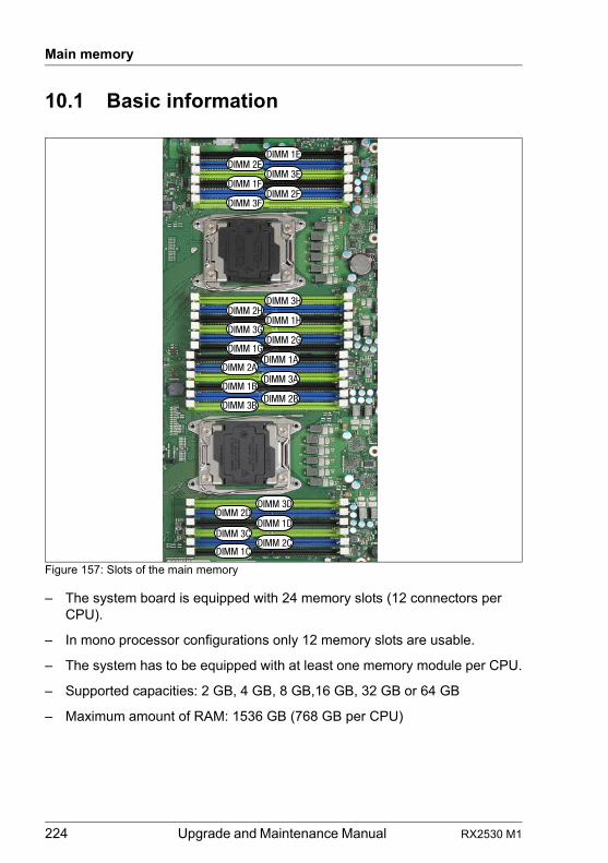
224 Upgrade and Maintenance Manual RX2530 M1
Main memory
10.1 Basic information
Figure 157: Slots of the main memory
– The system board is equipped with 24 memory slots (12 connectors per CPU).
– In mono processor configurations only 12 memory slots are usable.
– The system has to be equipped with at least one memory module per CPU.
– Supported capacities: 2 GB, 4 GB, 8 GB,16 GB, 32 GB or 64 GB
– Maximum amount of RAM: 1536 GB (768 GB per CPU)
DIMM 1E
DIMM 3HDIMM 2H
DIMM 1ADIMM 1G
DIMM 3FDIMM 2F
DIMM 1FDIMM 3E
DIMM 2E
DIMM 3D
DIMM 3C
DIMM 2D
DIMM 1H
DIMM 2GDIMM 3G
DIMM 2A
DIMM 1BDIMM 3A
DIMM 3BDIMM 2B
DIMM 1C
DIMM 1D
DIMM 2C
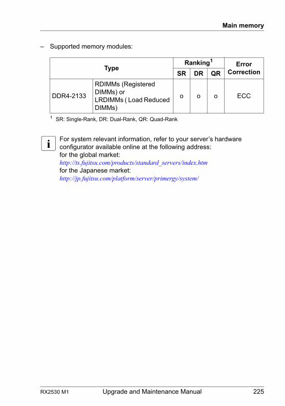
RX2530 M1 Upgrade and Maintenance Manual 225
Main memory
– Supported memory modules:
I For system relevant information, refer to your server’s hardware configurator available online at the following address:for the global market:http://ts.fujitsu.com/products/standard_servers/index.htm for the Japanese market:http://jp.fujitsu.com/platform/server/primergy/system/
TypeRanking1
1 SR: Single-Rank, DR: Dual-Rank, QR: Quad-Rank
Error CorrectionSR DR QR
DDR4-2133
RDIMMs (Registered DIMMs) or LRDIMMs ( Load Reduced DIMMs)
o o o ECC
226 Upgrade and Maintenance Manual RX2530 M1
Main memory
10.1.1 Population rules
– Populate memory slot 1 / channel A (DIMM 1A) first.
– In case of dual processor configurations, populate memory slot 1 / channel D (DIMM 1D) second.
– Within all channels, memory slot 1 must be populated prior to slot 2.(for all CPUs).
– If memory modules with different ranks are used, always populate the higher number rank DIMM first (starting from slot 1).
– If memory modules with different capacities are used:– Populate modules with higher capacities first.– Within a channel, populate modules in descending order of capacity.
– If memory modules with different speeds are used, the lowest clock rate applies for all DIMMs. Regardless of the mode, all DIMMs will run at the highest common frequency that is allowed by the SPD Data of the DIMMs and the maximum speed of the selected configuration.
– RDIMMs and LRDIMMs are allowed.
– Only ECC DIMMs are allowed.
– Mixing of quad-rank DIMMs in one channel and three DIMMs in another channel (3DPC) on the same CPU is not allowed.
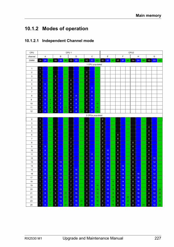
RX2530 M1 Upgrade and Maintenance Manual 227
Main memory
10.1.2 Modes of operation
10.1.2.1 Independent Channel mode
2 1 2
3 1 3 2
4 1 3 2 4
5 1 5 3 2 4
6 1 5 3 2 6 4
7 1 5 7 3 2 6 4
8 1 5 7 3 2 6 8 4
9 1 9 5 7 3 2 6 8 4
10 1 9 5 7 3 2 10 6 8 4
11 1 9 5 7 3 11 2 10 6 8 4
12 1 9 5 7 3 11 2 10 6 8 4 12
13 1 9 5 13 7 3 11 2 10 6 8 4 12
14 1 9 5 13 7 3 11 2 10 6 14 8 4 12
15 1 9 5 13 7 15 3 11 2 10 6 14 8 4 12
16 1 9 5 13 7 15 3 11 2 10 6 14 8 16 4 12
17 1 9 17 5 13 7 15 3 11 2 10 6 14 8 16 4 12
18 1 9 17 5 13 7 15 3 11 2 10 18 6 14 8 16 4 12
19 1 9 17 5 13 7 15 3 11 19 2 10 18 6 14 8 16 4 12
20 1 9 17 5 13 7 15 3 11 19 2 10 18 6 14 8 16 4 12 20
21 1 9 17 5 13 21 7 15 3 11 19 2 10 18 6 14 8 16 4 12 20
22 1 9 17 5 13 21 7 15 3 11 19 2 10 18 6 14 22 8 16 4 12 20
23 1 9 17 5 13 21 7 15 23 3 11 19 2 10 18 6 14 22 8 16 4 12 20
24 1 9 17 5 13 21 7 15 23 3 11 19 2 10 18 6 14 22 8 16 24 4 12 20
CPU CPU 1 CPU2
channel A B D C E F H G
DIMM 1A 2A 3A 1B 2B 3B 1D 2D 3D 1C 2C 3C 1E 2E 3E 1F 2F 3F 1H 2H 3H 1G 2G 3G
1 CPU populated
1 1
2 1 2
3 1 3 2
4 1 3 4 2
5 1 5 3 4 2
6 1 5 3 4 2 6
7 1 5 3 7 4 2 6
8 1 5 3 7 4 8 2 6
9 1 5 9 3 7 4 8 2 6
10 1 5 9 3 7 4 8 2 6 10
11 1 5 9 3 7 11 4 8 2 6 10
12 1 5 9 3 7 11 4 8 12 2 6 10
2 CPUs populated
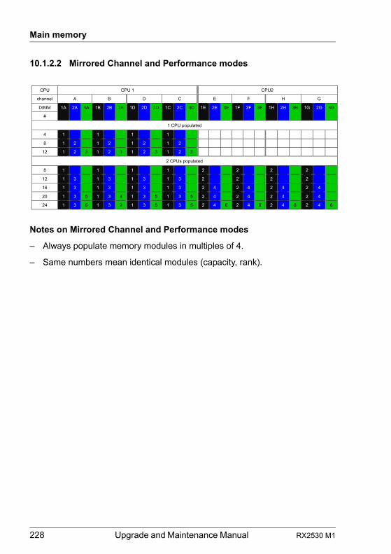
228 Upgrade and Maintenance Manual RX2530 M1
Main memory
10.1.2.2 Mirrored Channel and Performance modes
Notes on Mirrored Channel and Performance modes
– Always populate memory modules in multiples of 4.
– Same numbers mean identical modules (capacity, rank).
CPU CPU 1 CPU2
channel A B D C E F H G
DIMM 1A 2A 3A 1B 2B 3B 1D 2D 3D 1C 2C 3C 1E 2E 3E 1F 2F 3F 1H 2H 3H 1G 2G 3G
#
1 CPU populated
4 1 1 1 1
8 1 2 1 2 1 2 1 2
12 1 2 3 1 2 3 1 2 3 1 2 3
2 CPUs populated
8 1 1 1 1 2 2 2 2
12 1 3 1 3 1 3 1 3 2 2 2 2
16 1 3 1 3 1 3 1 3 2 4 2 4 2 4 2 4
20 1 3 5 1 3 9 1 3 5 1 3 5 2 4 2 4 2 4 2 4
24 1 3 5 1 3 9 1 3 5 1 3 5 2 4 6 2 4 6 2 4 6 2 4 6
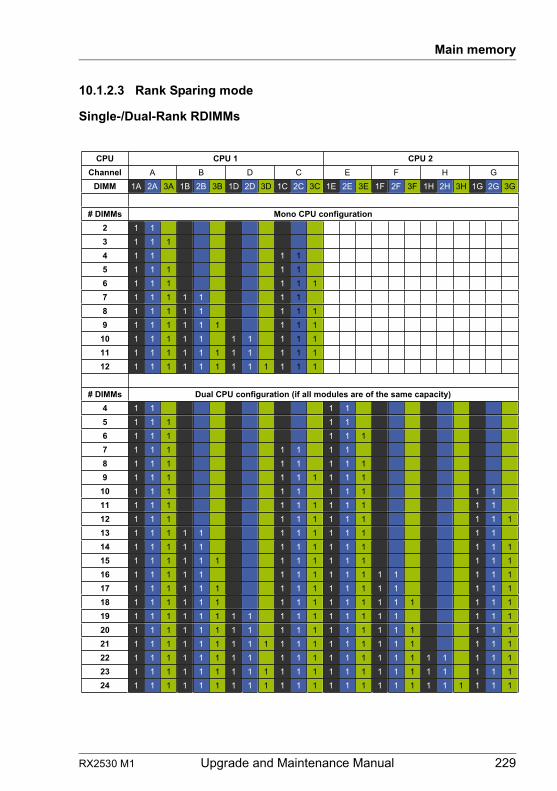
RX2530 M1 Upgrade and Maintenance Manual 229
Main memory
10.1.2.3 Rank Sparing mode
Single-/Dual-Rank RDIMMs
2 UPC 1 UPC UPCChannel A B D C E F H G
DIMM 1A 2A 3A 1B 2B 3B 1D 2D 3D 1C 2C 3C 1E 2E 3E 1F 2F 3F 1H 2H 3H 1G 2G 3G
noitarugifnoc UPC onoM sMMID #2 1 13 1 1 14 1 1 1 15 1 1 1 1 16 1 1 1 1 1 17 1 1 1 1 1 1 18 1 1 1 1 1 1 1 19 1 1 1 1 1 1 1 1 1
10 1 1 1 1 1 1 1 1 1 111 1 1 1 1 1 1 1 1 1 1 112 1 1 1 1 1 1 1 1 1 1 1 1
# DIMMs Dual CPU configuration (if all modules are of the same capacity) 4 1 1 1 15 1 1 1 1 16 1 1 1 1 1 17 1 1 1 1 1 1 18 1 1 1 1 1 1 1 19 1 1 1 1 1 1 1 1 1
10 1 1 1 1 1 1 1 1 1 111 1 1 1 1 1 1 1 1 1 1 112 1 1 1 1 1 1 1 1 1 1 1 113 1 1 1 1 1 1 1 1 1 1 1 1 114 1 1 1 1 1 1 1 1 1 1 1 1 1 115 1 1 1 1 1 1 1 1 1 1 1 1 1 1 116 1 1 1 1 1 1 1 1 1 1 1 1 1 1 1 117 1 1 1 1 1 1 1 1 1 1 1 1 1 1 1 1 118 1 1 1 1 1 1 1 1 1 1 1 1 1 1 1 1 1 119 1 1 1 1 1 1 1 1 1 1 1 1 1 1 1 1 1 1 120 1 1 1 1 1 1 1 1 1 1 1 1 1 1 1 1 1 1 1 121 1 1 1 1 1 1 1 1 1 1 1 1 1 1 1 1 1 1 1 1 122 1 1 1 1 1 1 1 1 1 1 1 1 1 1 1 1 1 1 1 1 1 123 1 1 1 1 1 1 1 1 1 1 1 1 1 1 1 1 1 1 1 1 1 1 124 1 1 1 1 1 1 1 1 1 1 1 1 1 1 1 1 1 1 1 1 1 1 1 1
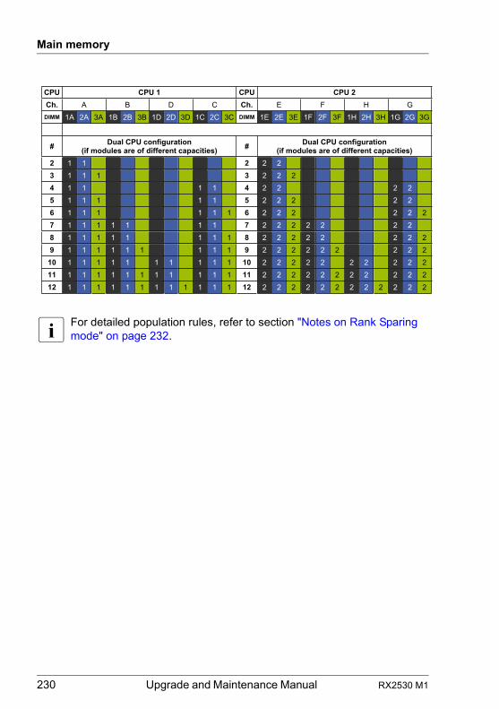
230 Upgrade and Maintenance Manual RX2530 M1
Main memory
I For detailed population rules, refer to section "Notes on Rank Sparing mode" on page 232.
2 UPCUPC 1 UPC UPCCh. A B D C Ch. E F H G
DIMM 1A 2A 3A 1B 2B 3B 1D 2D 3D 1C 2C 3C DIMM 1E 2E 3E 1F 2F 3F 1H 2H 3H 1G 2G 3G
# Dual CPU configuration (if modules are of different capacities) # Dual CPU configuration
(if modules are of different capacities)2 1 1 2 2 23 1 1 1 3 2 2 24 1 1 1 1 4 2 2 2 25 1 1 1 1 1 5 2 2 2 2 26 1 1 1 1 1 1 6 2 2 2 2 2 27 1 1 1 1 1 1 1 7 2 2 2 2 2 2 28 1 1 1 1 1 1 1 1 8 2 2 2 2 2 2 2 29 1 1 1 1 1 1 1 1 1 9 2 2 2 2 2 2 2 2 2
10 1 1 1 1 1 1 1 1 1 1 10 2 2 2 2 2 2 2 2 2 211 1 1 1 1 1 1 1 1 1 1 1 11 2 2 2 2 2 2 2 2 2 2 212 1 1 1 1 1 1 1 1 1 1 1 1 12 2 2 2 2 2 2 2 2 2 2 2 2
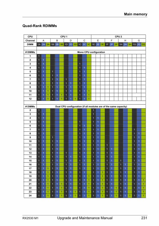
RX2530 M1 Upgrade and Maintenance Manual 231
Main memory
Quad-Rank RDIMMs
2 UPC 1 UPC UPCChannel A B D C E F H G
DIMM 1A 2A 3A 1B 2B 3B 1D 2D 3D 1C 2C 3C 1E 2E 3E 1F 2F 3F 1H 2H 3H 1G 2G 3G
noitarugifnoc UPC onoM sMMID #1 12 1 13 1 1 14 1 1 1 15 1 1 1 1 16 1 1 1 1 1 17 1 1 1 1 1 1 18 1 1 1 1 1 1 1 19 1 1 1 1 1 1 1 1 1
10 1 1 1 1 1 1 1 1 1 111 1 1 1 1 1 1 1 1 1 1 112 1 1 1 1 1 1 1 1 1 1 1 1
# DIMMs Dual CPU configuration (if all modules are of the same capacity) 2 1 13 1 1 14 1 1 1 15 1 1 1 1 16 1 1 1 1 1 17 1 1 1 1 1 1 18 1 1 1 1 1 1 1 19 1 1 1 1 1 1 1 1 1
10 1 1 1 1 1 1 1 1 1 111 1 1 1 1 1 1 1 1 1 1 112 1 1 1 1 1 1 1 1 1 1 1 113 1 1 1 1 1 1 1 1 1 1 1 1 114 1 1 1 1 1 1 1 1 1 1 1 1 1 115 1 1 1 1 1 1 1 1 1 1 1 1 1 1 116 1 1 1 1 1 1 1 1 1 1 1 1 1 1 1 117 1 1 1 1 1 1 1 1 1 1 1 1 1 1 1 1 118 1 1 1 1 1 1 1 1 1 1 1 1 1 1 1 1 1 119 1 1 1 1 1 1 1 1 1 1 1 1 1 1 1 1 1 1 120 1 1 1 1 1 1 1 1 1 1 1 1 1 1 1 1 1 1 1 121 1 1 1 1 1 1 1 1 1 1 1 1 1 1 1 1 1 1 1 1 122 1 1 1 1 1 1 1 1 1 1 1 1 1 1 1 1 1 1 1 1 1 123 1 1 1 1 1 1 1 1 1 1 1 1 1 1 1 1 1 1 1 1 1 1 124 1 1 1 1 1 1 1 1 1 1 1 1 1 1 1 1 1 1 1 1 1 1 1 1
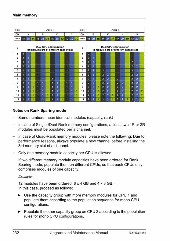
232 Upgrade and Maintenance Manual RX2530 M1
Main memory
Notes on Rank Sparing mode
– Same numbers mean identical modules (capacity, rank)
– In case of Single-/Dual-Rank memory configurations, at least two 1R or 2R modules must be populated per a channel.
– In case of Quad-Rank memory modules, please note the following: Due to performance reasons, always populate a new channel before installing the 3rd memory slot of a channel.
– Only one memory module capacity per CPU is allowed.
If two different memory module capacities have been ordered for Rank Sparing mode, populate them on different CPUs, so that each CPUs only comprises modules of one capacity
Example:
12 modules have been ordered, 8 x 4 GB and 4 x 8 GB.In this case, proceed as follows:
Ê Use the capacity group with more memory modules for CPU 1 and populate them according to the population sequence for mono CPU configurations.
Ê Populate the other capacity group on CPU 2 according to the population rules for mono CPU configurations.
2 UPCUPC 1 UPC UPCCh. A B D C Ch. E F H G
DIMM 1A 2A 3A 1B 2B 3B 1D 2D 3D 1C 2C 3C DIMM 1E 2E 3E 1F 2F 3F 1H 2H 3H 1G 2G 3G
# Dual CPU configuration (if modules are of different capacities) # Dual CPU configuration
(if modules are of different capacities)1 1 1 22 1 1 2 2 23 1 1 1 3 2 2 24 1 1 1 1 4 2 2 2 25 1 1 1 1 1 5 2 2 2 2 26 1 1 1 1 1 1 6 2 2 2 2 2 27 1 1 1 1 1 1 1 7 2 2 2 2 2 2 28 1 1 1 1 1 1 1 1 8 2 2 2 2 2 2 2 29 1 1 1 1 1 1 1 1 1 9 2 2 2 2 2 2 2 2 2
10 1 1 1 1 1 1 1 1 1 1 10 2 2 2 2 2 2 2 2 2 211 1 1 1 1 1 1 1 1 1 1 1 11 2 2 2 2 2 2 2 2 2 2 212 1 1 1 1 1 1 1 1 1 1 1 1 12 2 2 2 2 2 2 2 2 2 2 2 2
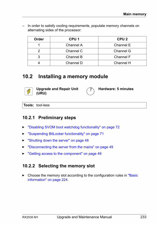
RX2530 M1 Upgrade and Maintenance Manual 233
Main memory
– In order to satisfy cooling requirements, populate memory channels on alternating sides of the processor:
10.2 Installing a memory module
10.2.1 Preliminary steps
Ê "Disabling SVOM boot watchdog functionality" on page 72
Ê "Suspending BitLocker functionality" on page 71
Ê "Shutting down the server" on page 48
Ê "Disconnecting the server from the mains" on page 49
Ê "Getting access to the component" on page 49
10.2.2 Selecting the memory slot
Ê Choose the memory slot according to the configuration rules in "Basic information" on page 224.
Order CPU 1 CPU 2
1 Channel A Channel E
2 Channel C Channel G
3 Channel B Channel F
4 Channel D Channel H
Upgrade and Repair Unit(URU)
Hardware: 5 minutes
Tools: tool-less
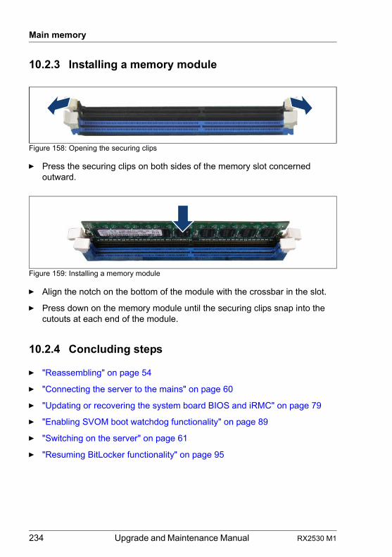
234 Upgrade and Maintenance Manual RX2530 M1
Main memory
10.2.3 Installing a memory module
Figure 158: Opening the securing clips
Ê Press the securing clips on both sides of the memory slot concerned outward.
Figure 159: Installing a memory module
Ê Align the notch on the bottom of the module with the crossbar in the slot.
Ê Press down on the memory module until the securing clips snap into the cutouts at each end of the module.
10.2.4 Concluding steps
Ê "Reassembling" on page 54
Ê "Connecting the server to the mains" on page 60
Ê "Updating or recovering the system board BIOS and iRMC" on page 79
Ê "Enabling SVOM boot watchdog functionality" on page 89
Ê "Switching on the server" on page 61
Ê "Resuming BitLocker functionality" on page 95
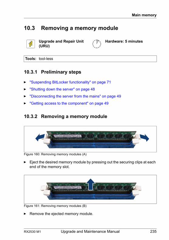
RX2530 M1 Upgrade and Maintenance Manual 235
Main memory
10.3 Removing a memory module
10.3.1 Preliminary steps
Ê "Suspending BitLocker functionality" on page 71
Ê "Shutting down the server" on page 48
Ê "Disconnecting the server from the mains" on page 49
Ê "Getting access to the component" on page 49
10.3.2 Removing a memory module
Figure 160: Removing memory modules (A)
Ê Eject the desired memory module by pressing out the securing clips at each end of the memory slot.
Figure 161: Removing memory modules (B)
Ê Remove the ejected memory module.
Upgrade and Repair Unit(URU)
Hardware: 5 minutes
Tools: tool-less
236 Upgrade and Maintenance Manual RX2530 M1
Main memory
10.3.3 Concluding steps
Ê "Reassembling" on page 54
Ê "Connecting the server to the mains" on page 60
Ê "Switching on the server" on page 61
Ê "Resuming BitLocker functionality" on page 95
10.4 Replacing a memory module
10.4.1 Preliminary steps
Ê "Locating the defective server" on page 45
Ê "Disabling SVOM boot watchdog functionality" on page 72
Ê "Suspending BitLocker functionality" on page 71
Ê "Shutting down the server" on page 48
Ê "Disconnecting the server from the mains" on page 49
Ê "Getting access to the component" on page 49
Ê "Locating the defective component" on page 47
10.4.2 Removing the defective memory module
Ê Remove the memory module as described in section "Removing a memory module" on page 235.
Upgrade and Repair Unit(URU)
Hardware: 5 minutes
Tools: tool-less
RX2530 M1 Upgrade and Maintenance Manual 237
Main memory
10.4.3 Installing the new memory module
Ê Install the memory module as described in section "Installing a memory module" on page 234.
10.4.4 Concluding steps
Ê "Reassembling" on page 54
Ê "Connecting the server to the mains" on page 60
Ê "Updating or recovering the system board BIOS and iRMC" on page 79
Ê "Resetting the error status after replacing memory modules or processors" on page 86
Ê "Enabling replaced components in the system BIOS" on page 90
Ê "Verifying the memory mode" on page 91
Ê "Enabling SVOM boot watchdog functionality" on page 89
Ê "Switching on the server" on page 61
Ê "Resuming BitLocker functionality" on page 95
238 Upgrade and Maintenance Manual RX2530 M1
Main memory
RX2530 M1 Upgrade and Maintenance Manual 239
11 Processors
Safety notes
V CAUTION!
● Do not install unsupported processors. For further information on supported processors, refer to section "Supported processors" on page 241.
● Circuit boards and soldered parts of internal options are exposed and can be damaged by static electricity. Always discharge static build-up (e.g. by touching a grounded object) before handling electrostatic-sensitive devices (ESDs).
● Do not touch the circuitry on boards or soldered parts. Hold circuit boards by their metallic areas or edges.
● When removing or installing the processor, be careful not to touch or bend the spring contacts on the processor socket.
● Never touch the underside of the processor. Even minor soiling such as grease from the skin can impair the processor’s operation or destroy the processor.
● For further safety information, please refer to chapter "Important information" on page 33.
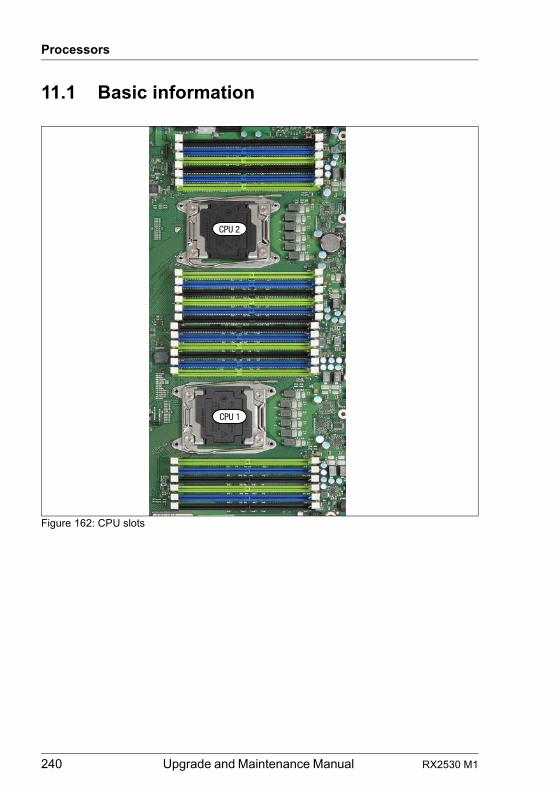
240 Upgrade and Maintenance Manual RX2530 M1
Processors
11.1 Basic information
Figure 162: CPU slots
CPU 2
CPU 1
RX2530 M1 Upgrade and Maintenance Manual 241
Processors
11.1.1 Supported processors
– up to two Intel® 4-/6-/8-/10-/12-Core processors (Xeon E5-26xxv3 or E5-26xxLv3)
– two processor sockets LGA 2011– supported CPUs from 55 W to 145 W– core frequencies of more than 3.5 GHz
I For system relevant information, refer to your server’s hardware configurator available online at the following address:for the global market:http://ts.fujitsu.com/products/standard_servers/index.htm for the Japanese market:http://jp.fujitsu.com/platform/server/primergy/system/
11.1.2 General equipping rules
Both CPUs must be of the same type.
11.2 Upgrading to dual processor configuration
V CAUTION!
– Processors are modules which are extremely sensitive to electro-static discharges and therefore must always be handled with care. After a processor has been removed from its protective sleeve or from its socket, place it with its smooth side down on a non-conducting, antistatic surface. Never push a processor over a surface.
– Only processors of the same type may be used on the system board. That means the number of the internal processor cores as well as the primary clock and the QPI frequency have to be the same.
– For dual operation, use a suitable multiprocessor operating system.
Upgrade and Repair Unit(URU)
Hardware: 15 minutesSoftware: 5 minutes
Tools: Phillips PH2 / (+) No. 2 screw driver
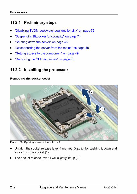
242 Upgrade and Maintenance Manual RX2530 M1
Processors
11.2.1 Preliminary steps
Ê "Disabling SVOM boot watchdog functionality" on page 72
Ê "Suspending BitLocker functionality" on page 71
Ê "Shutting down the server" on page 48
Ê "Disconnecting the server from the mains" on page 49
Ê "Getting access to the component" on page 49
Ê "Removing the CPU air guides" on page 68
11.2.2 Installing the processor
Removing the socket cover
Figure 163: Opening socket release lever 1
Ê Unlatch the socket release lever 1 marked Open 1st by pushing it down and away from the socket (1).
Ê The socket release lever 1 will slightly lift up (2).
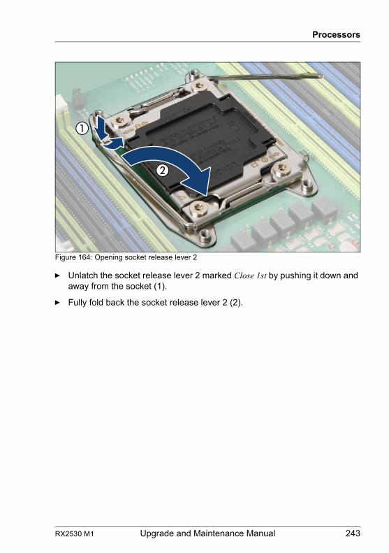
RX2530 M1 Upgrade and Maintenance Manual 243
Processors
Figure 164: Opening socket release lever 2
Ê Unlatch the socket release lever 2 marked Close 1st by pushing it down and away from the socket (1).
Ê Fully fold back the socket release lever 2 (2).
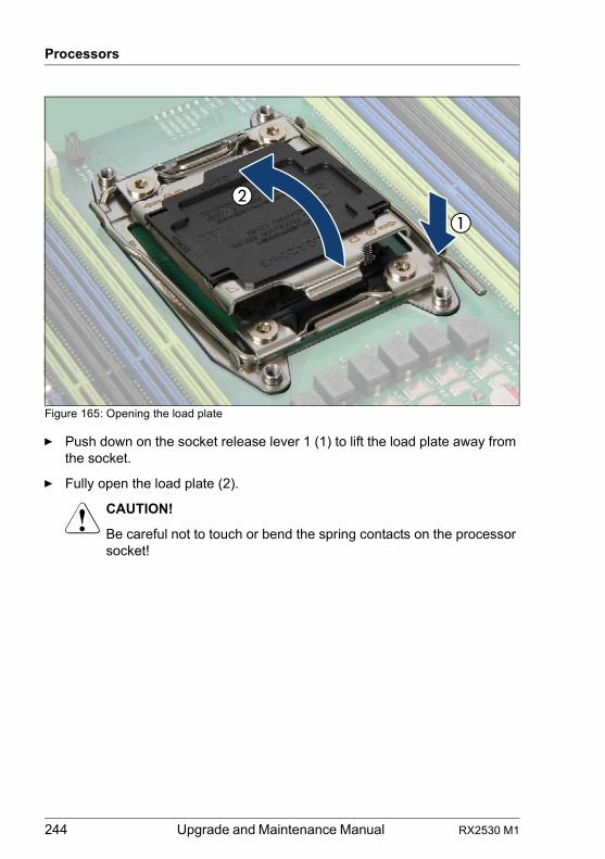
244 Upgrade and Maintenance Manual RX2530 M1
Processors
Figure 165: Opening the load plate
Ê Push down on the socket release lever 1 (1) to lift the load plate away from the socket.
Ê Fully open the load plate (2).
V CAUTION!
Be careful not to touch or bend the spring contacts on the processor socket!
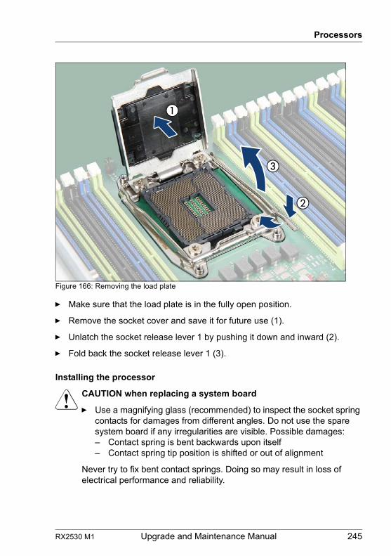
RX2530 M1 Upgrade and Maintenance Manual 245
Processors
Figure 166: Removing the load plate
Ê Make sure that the load plate is in the fully open position.
Ê Remove the socket cover and save it for future use (1).
Ê Unlatch the socket release lever 1 by pushing it down and inward (2).
Ê Fold back the socket release lever 1 (3).
Installing the processor
V CAUTION when replacing a system board
Ê Use a magnifying glass (recommended) to inspect the socket spring contacts for damages from different angles. Do not use the spare system board if any irregularities are visible. Possible damages:– Contact spring is bent backwards upon itself– Contact spring tip position is shifted or out of alignment
Never try to fix bent contact springs. Doing so may result in loss of electrical performance and reliability.
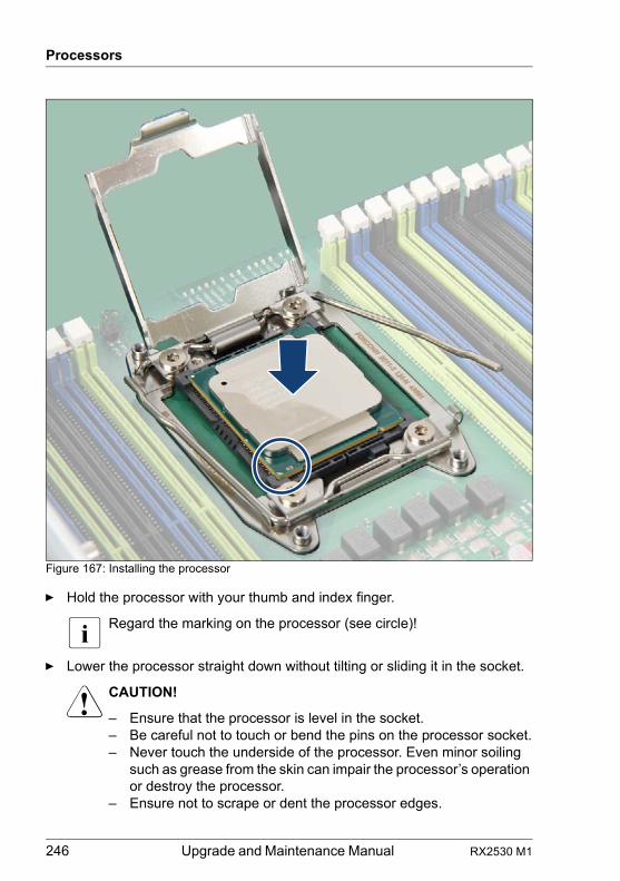
246 Upgrade and Maintenance Manual RX2530 M1
Processors
Figure 167: Installing the processor
Ê Hold the processor with your thumb and index finger.
I Regard the marking on the processor (see circle)!
Ê Lower the processor straight down without tilting or sliding it in the socket.
V CAUTION!
– Ensure that the processor is level in the socket.– Be careful not to touch or bend the pins on the processor socket.– Never touch the underside of the processor. Even minor soiling
such as grease from the skin can impair the processor’s operation or destroy the processor.
– Ensure not to scrape or dent the processor edges.
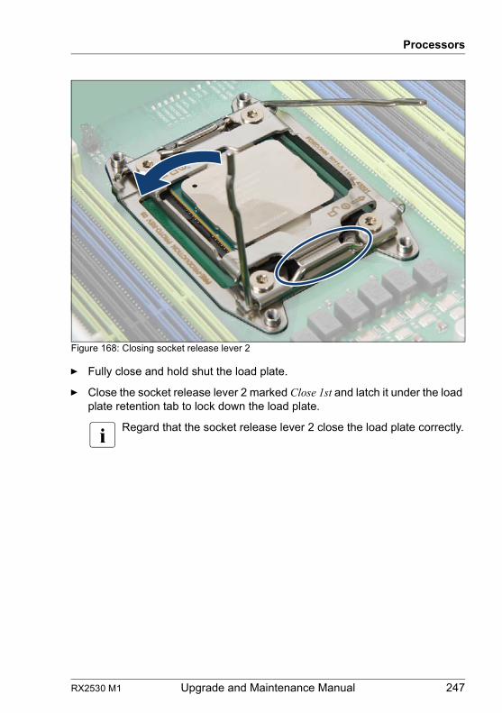
RX2530 M1 Upgrade and Maintenance Manual 247
Processors
Figure 168: Closing socket release lever 2
Ê Fully close and hold shut the load plate.
Ê Close the socket release lever 2 marked Close 1st and latch it under the load plate retention tab to lock down the load plate.
I Regard that the socket release lever 2 close the load plate correctly.
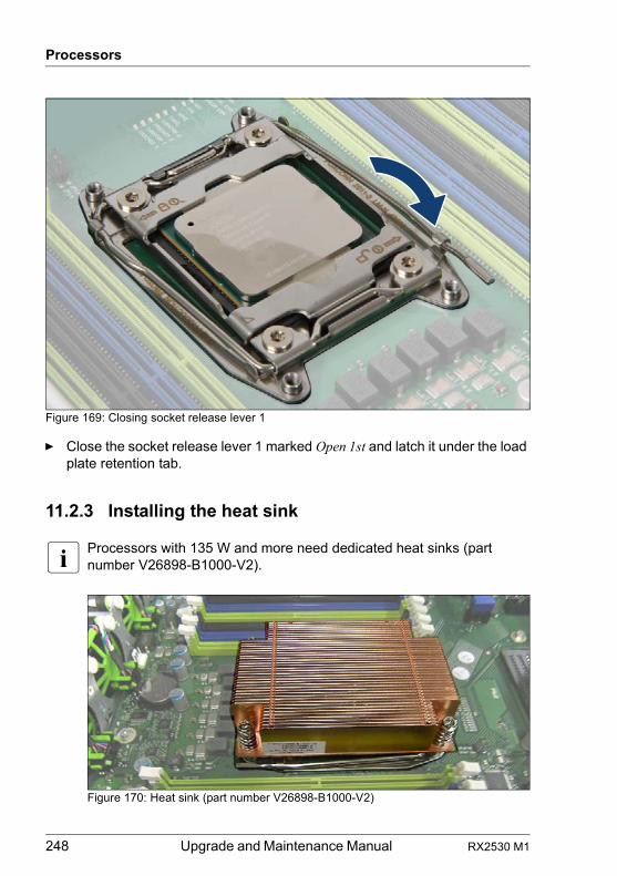
248 Upgrade and Maintenance Manual RX2530 M1
Processors
Figure 169: Closing socket release lever 1
Ê Close the socket release lever 1 marked Open 1st and latch it under the load plate retention tab.
11.2.3 Installing the heat sink
I Processors with 135 W and more need dedicated heat sinks (part number V26898-B1000-V2).
Figure 170: Heat sink (part number V26898-B1000-V2)
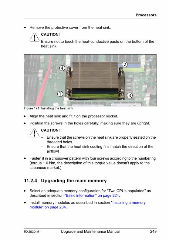
RX2530 M1 Upgrade and Maintenance Manual 249
Processors
Ê Remove the protective cover from the heat sink.
V CAUTION!
Ensure not to touch the heat-conductive paste on the bottom of the heat sink.
Figure 171: Installing the heat sink
Ê Align the heat sink and fit it on the processor socket.
Ê Position the screws in the holes carefully, making sure they are upright.
V CAUTION!
– Ensure that the screws on the heat sink are properly seated on the threaded holes.
– Ensure that the heat sink cooling fins match the direction of the airflow!
Ê Fasten it in a crossover pattern with four screws according to the numbering (torque 1.0 Nm, the description of this torque value doesn't apply to the Japanese market.)
11.2.4 Upgrading the main memory
Ê Select an adequate memory configuration for "Two CPUs populated" as described in section "Basic information" on page 224.
Ê Install memory modules as described in section "Installing a memory module" on page 234.
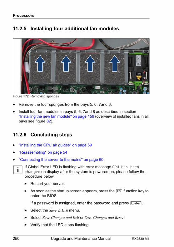
250 Upgrade and Maintenance Manual RX2530 M1
Processors
11.2.5 Installing four additional fan modules
Figure 172: Removing sponges
Ê Remove the four sponges from the bays 5, 6, 7and 8.
Ê Install four fan modules in bays 5, 6, 7and 8 as described in section "Installing the new fan module" on page 159 (overview of installed fans in all bays see figure 82).
11.2.6 Concluding steps
Ê "Installing the CPU air guides" on page 69
Ê "Reassembling" on page 54
Ê "Connecting the server to the mains" on page 60
I If Global Error LED is flashing with error message CPU has been changed on display after the system is powered on, please follow the procedure below.
Ê Restart your server.
Ê As soon as the startup screen appears, press the [F2] function key to enter the BIOS.
If a password is assigned, enter the password and press [Enter].
Ê Select the Save & Exit menu.
Ê Select Save Changes and Exit or Save Changes and Reset.
Ê Verify that the LED stops flashing.
RX2530 M1 Upgrade and Maintenance Manual 251
Processors
Ê "Updating or recovering the system board BIOS and iRMC" on page 79
Ê "Enabling SVOM boot watchdog functionality" on page 89
Ê "Switching on the server" on page 61
Ê "Resuming BitLocker functionality" on page 95
11.3 Replacing a processor
V CAUTION!
Processors are modules which are extremely sensitive to electrostatic discharges and therefore must always be handled with care. After a processor has been removed from its protective sleeve or from its socket, place it with its smooth side down on a non-conducting, antistatic surface. Never push a processor over a surface.
11.3.1 Preliminary steps
Ê "Locating the defective server" on page 45
Ê "Disabling SVOM boot watchdog functionality" on page 72
Ê "Suspending BitLocker functionality" on page 71
Ê "Shutting down the server" on page 48
Ê "Disconnecting the server from the mains" on page 49
Ê "Getting access to the component" on page 49
Ê "Removing the CPU air guides" on page 68
Field Replaceable Unit(FRU)
Hardware: 15 minutesSoftware: 5 minutes
Tools: Phillips PH2 / (+) No. 2 screw driver
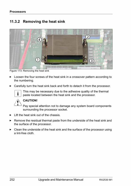
252 Upgrade and Maintenance Manual RX2530 M1
Processors
11.3.2 Removing the heat sink
Figure 173: Removing the heat sink
Ê Loosen the four screws of the heat sink in a crossover pattern according to the numbering.
Ê Carefully turn the heat sink back and forth to detach it from the processor.
I This may be necessary due to the adhesive quality of the thermal paste located between the heat sink and the processor.
V CAUTION!
Pay special attention not to damage any system board components surrounding the processor socket.
Ê Lift the heat sink out of the chassis.
Ê Remove the residual thermal paste from the underside of the heat sink and the surface of the processor.
Ê Clean the underside of the heat sink and the surface of the processor using a lint-free cloth.
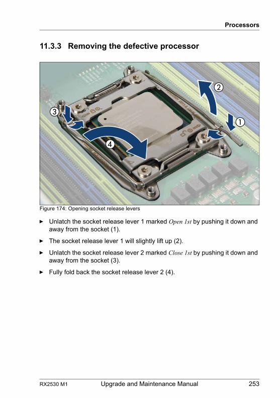
RX2530 M1 Upgrade and Maintenance Manual 253
Processors
11.3.3 Removing the defective processor
Figure 174: Opening socket release levers
Ê Unlatch the socket release lever 1 marked Open 1st by pushing it down and away from the socket (1).
Ê The socket release lever 1 will slightly lift up (2).
Ê Unlatch the socket release lever 2 marked Close 1st by pushing it down and away from the socket (3).
Ê Fully fold back the socket release lever 2 (4).
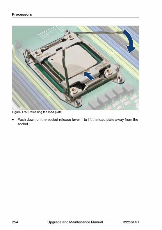
254 Upgrade and Maintenance Manual RX2530 M1
Processors
Figure 175: Releasing the load plate
Ê Push down on the socket release lever 1 to lift the load plate away from the socket.
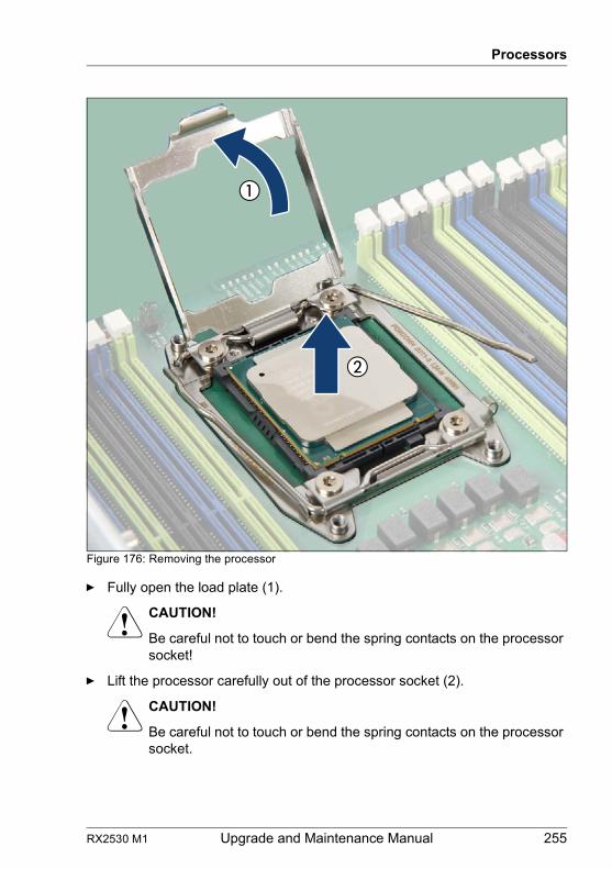
RX2530 M1 Upgrade and Maintenance Manual 255
Processors
Figure 176: Removing the processor
Ê Fully open the load plate (1).
V CAUTION!
Be careful not to touch or bend the spring contacts on the processor socket!
Ê Lift the processor carefully out of the processor socket (2).
V CAUTION!
Be careful not to touch or bend the spring contacts on the processor socket.
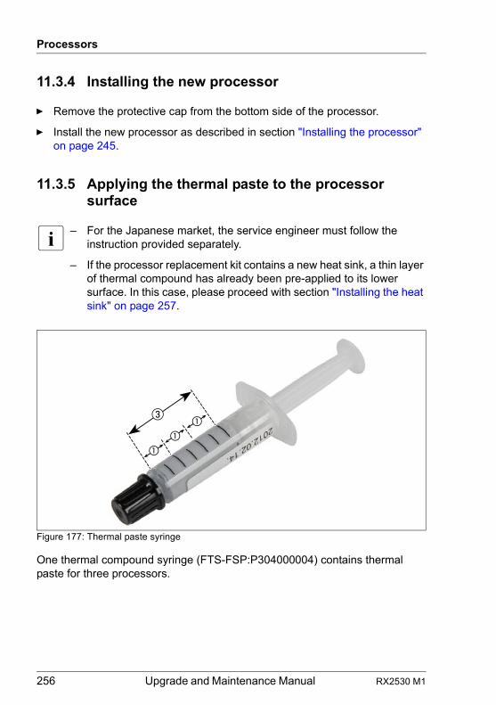
256 Upgrade and Maintenance Manual RX2530 M1
Processors
11.3.4 Installing the new processor
Ê Remove the protective cap from the bottom side of the processor.
Ê Install the new processor as described in section "Installing the processor" on page 245.
11.3.5 Applying the thermal paste to the processor surface
I – For the Japanese market, the service engineer must follow the instruction provided separately.
– If the processor replacement kit contains a new heat sink, a thin layer of thermal compound has already been pre-applied to its lower surface. In this case, please proceed with section "Installing the heat sink" on page 257.
Figure 177: Thermal paste syringe
One thermal compound syringe (FTS-FSP:P304000004) contains thermal paste for three processors.
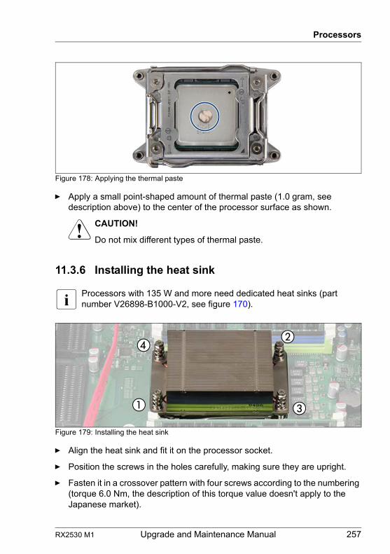
RX2530 M1 Upgrade and Maintenance Manual 257
Processors
Figure 178: Applying the thermal paste
Ê Apply a small point-shaped amount of thermal paste (1.0 gram, see description above) to the center of the processor surface as shown.
V CAUTION!
Do not mix different types of thermal paste.
11.3.6 Installing the heat sink
I Processors with 135 W and more need dedicated heat sinks (part number V26898-B1000-V2, see figure 170).
Figure 179: Installing the heat sink
Ê Align the heat sink and fit it on the processor socket.
Ê Position the screws in the holes carefully, making sure they are upright.
Ê Fasten it in a crossover pattern with four screws according to the numbering (torque 6.0 Nm, the description of this torque value doesn't apply to the Japanese market).
258 Upgrade and Maintenance Manual RX2530 M1
Processors
11.3.7 Concluding steps
Ê "Installing the CPU air guides" on page 69
Ê "Reassembling" on page 54
Ê "Connecting the server to the mains" on page 60
Ê "Updating or recovering the system board BIOS and iRMC" on page 79
Ê "Resetting the error status after replacing memory modules or processors" on page 86
Ê "Enabling SVOM boot watchdog functionality" on page 89
Ê "Switching on the server" on page 61
Ê "Resuming BitLocker functionality" on page 95
11.4 Replacing the heat sink
11.4.1 Preliminary steps
Ê "Locating the defective server" on page 45
Ê "Shutting down the server" on page 48
Ê "Disconnecting the server from the mains" on page 49
Ê "Getting access to the component" on page 49
Ê "Removing the CPU air guides" on page 68
11.4.2 Removing the defective heat sink
Ê Remove the heat sink as described in section "Removing the heat sink" on page 252.
Field Replaceable Unit(FRU)
Hardware: 15 minutes
Tools: Phillips PH2 / (+) No. 2 screw driver
RX2530 M1 Upgrade and Maintenance Manual 259
Processors
Ê Remove the residual thermal paste from the processor surface.
Ê Clean the processor surface using a lint-free cloth.
11.4.3 Installing the new heat sink
Ê Remove the protective cover on the underside of the heat sink.
V CAUTION!
Do not touch the thermal paste on the underside of the heat sink.
Ê Install the heat sink as described in section "Installing the heat sink" on page 257.
11.4.4 Concluding steps
Ê "Installing the CPU air guides" on page 69
Ê "Reassembling" on page 54
Ê "Connecting the server to the mains" on page 60
Ê "Switching on the server" on page 61
260 Upgrade and Maintenance Manual RX2530 M1
Processors
RX2530 M1 Upgrade and Maintenance Manual 261
12 Optical disk drive
Safety notes
V CAUTION!
● Before installing/removing an accessible drive to/from the server, turn off the server, all peripheral devices, and any other connected devices. Also unplug all power cables from the outlet. Failure to do so can cause electric shock.
● When installing an accessible drive, hold it by the side. Applying force to the top may cause failures.
● Do not touch the circuitry on boards and soldered parts. Hold the metallic areas or the edge of the circuit boards.
● The circuit boards and soldered parts of internal options are exposed and can be damaged by static electricity. Before handling them, first touch a metal part on the server to discharge static electricity from your body.
● Before installing an internal accessible drive, see the manual for the accessible drive.
● When forcing an accessible drive into a server, be careful so as not to pinch the cable etc. connected to an accessible drive.
● For further safety information, please refer to chapter "Important information" on page 33.
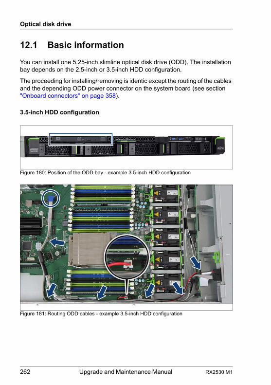
262 Upgrade and Maintenance Manual RX2530 M1
Optical disk drive
12.1 Basic information
You can install one 5.25-inch slimline optical disk drive (ODD). The installation bay depends on the 2.5-inch or 3.5-inch HDD configuration.
The proceeding for installing/removing is identic except the routing of the cables and the depending ODD power connector on the system board (see section "Onboard connectors" on page 358).
3.5-inch HDD configuration
Figure 180: Position of the ODD bay - example 3.5-inch HDD configuration
Figure 181: Routing ODD cables - example 3.5-inch HDD configuration
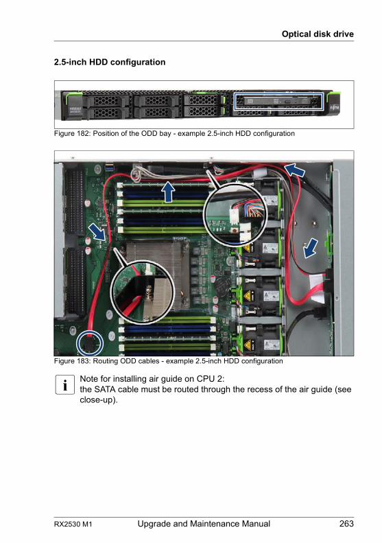
RX2530 M1 Upgrade and Maintenance Manual 263
Optical disk drive
2.5-inch HDD configuration
Figure 182: Position of the ODD bay - example 2.5-inch HDD configuration
Figure 183: Routing ODD cables - example 2.5-inch HDD configuration
I Note for installing air guide on CPU 2:the SATA cable must be routed through the recess of the air guide (see close-up).
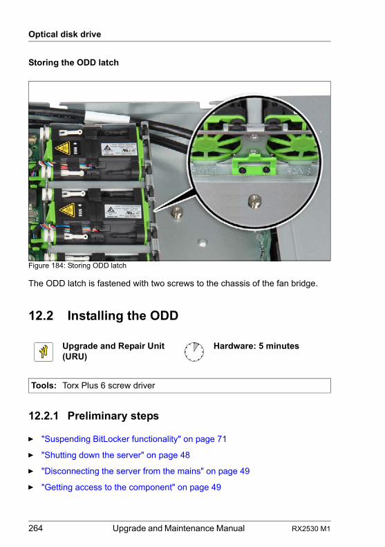
264 Upgrade and Maintenance Manual RX2530 M1
Optical disk drive
Storing the ODD latch
Figure 184: Storing ODD latch
The ODD latch is fastened with two screws to the chassis of the fan bridge.
12.2 Installing the ODD
12.2.1 Preliminary steps
Ê "Suspending BitLocker functionality" on page 71
Ê "Shutting down the server" on page 48
Ê "Disconnecting the server from the mains" on page 49
Ê "Getting access to the component" on page 49
Upgrade and Repair Unit(URU)
Hardware: 5 minutes
Tools: Torx Plus 6 screw driver
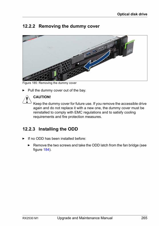
RX2530 M1 Upgrade and Maintenance Manual 265
Optical disk drive
12.2.2 Removing the dummy cover
Figure 185: Removing the dummy cover
Ê Pull the dummy cover out of the bay.
V CAUTION!
Keep the dummy cover for future use. If you remove the accessible drive again and do not replace it with a new one, the dummy cover must be reinstalled to comply with EMC regulations and to satisfy cooling requirements and fire protection measures.
12.2.3 Installing the ODD
Ê If no ODD has been installed before:
Ê Remove the two screws and take the ODD latch from the fan bridge (see figure 184).
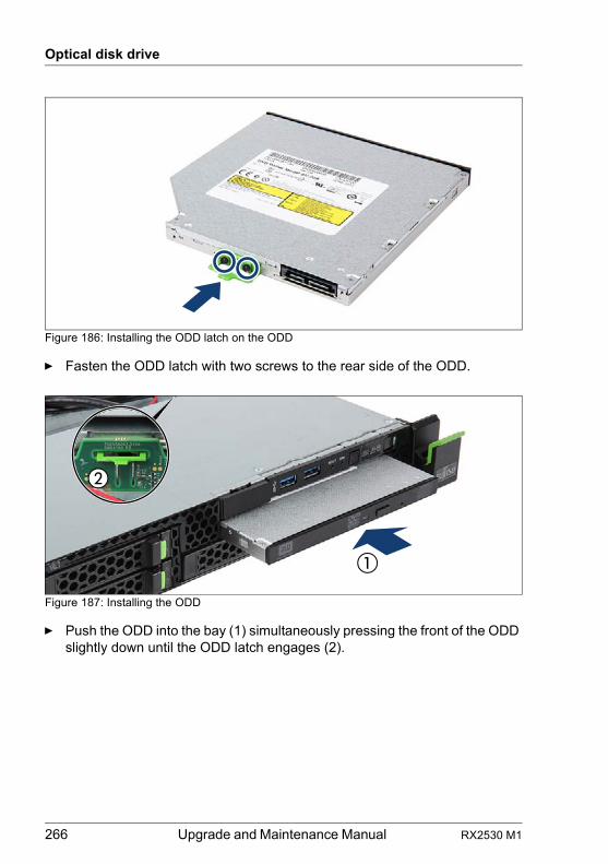
266 Upgrade and Maintenance Manual RX2530 M1
Optical disk drive
Figure 186: Installing the ODD latch on the ODD
Ê Fasten the ODD latch with two screws to the rear side of the ODD.
Figure 187: Installing the ODD
Ê Push the ODD into the bay (1) simultaneously pressing the front of the ODD slightly down until the ODD latch engages (2).
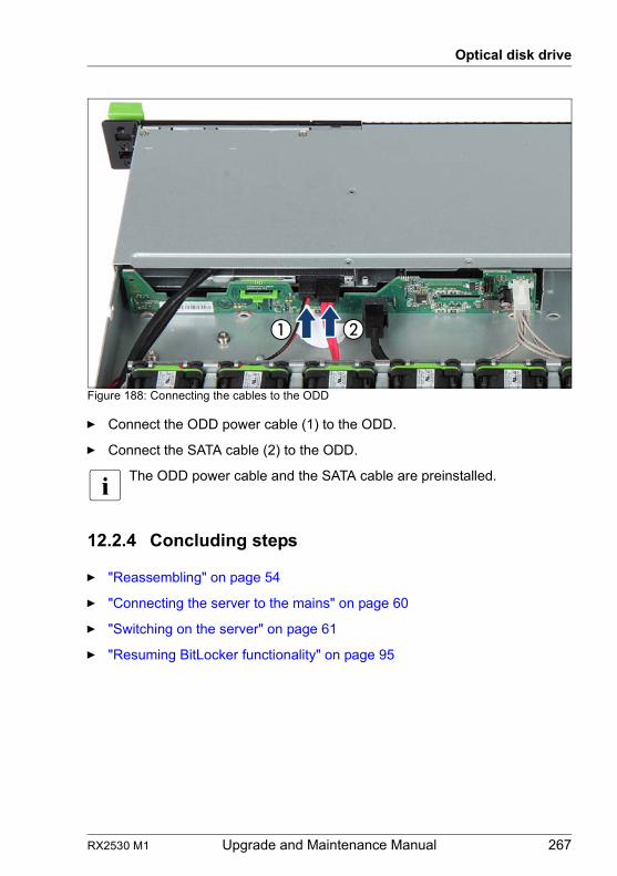
RX2530 M1 Upgrade and Maintenance Manual 267
Optical disk drive
Figure 188: Connecting the cables to the ODD
Ê Connect the ODD power cable (1) to the ODD.
Ê Connect the SATA cable (2) to the ODD.
I The ODD power cable and the SATA cable are preinstalled.
12.2.4 Concluding steps
Ê "Reassembling" on page 54
Ê "Connecting the server to the mains" on page 60
Ê "Switching on the server" on page 61
Ê "Resuming BitLocker functionality" on page 95
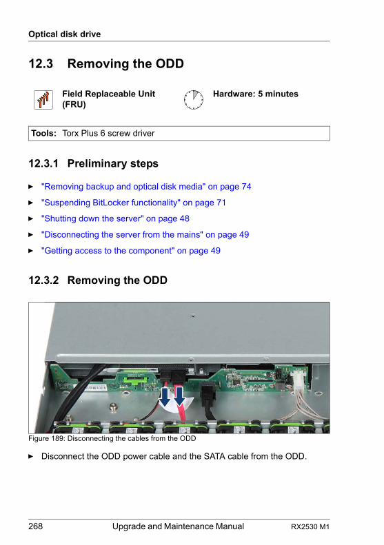
268 Upgrade and Maintenance Manual RX2530 M1
Optical disk drive
12.3 Removing the ODD
12.3.1 Preliminary steps
Ê "Removing backup and optical disk media" on page 74
Ê "Suspending BitLocker functionality" on page 71
Ê "Shutting down the server" on page 48
Ê "Disconnecting the server from the mains" on page 49
Ê "Getting access to the component" on page 49
12.3.2 Removing the ODD
Figure 189: Disconnecting the cables from the ODD
Ê Disconnect the ODD power cable and the SATA cable from the ODD.
Field Replaceable Unit(FRU)
Hardware: 5 minutes
Tools: Torx Plus 6 screw driver
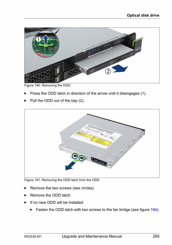
RX2530 M1 Upgrade and Maintenance Manual 269
Optical disk drive
Figure 190: Removing the ODD
Ê Press the ODD latch in direction of the arrow until it disengages (1).
Ê Pull the ODD out of the bay (2).
Figure 191: Removing the ODD latch from the ODD
Ê Remove the two screws (see circles).
Ê Remove the ODD latch.
Ê If no new ODD will be installed:
Ê Fasten the ODD latch with two screws to the fan bridge (see figure 184).
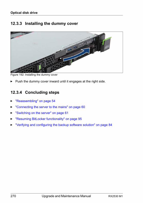
270 Upgrade and Maintenance Manual RX2530 M1
Optical disk drive
12.3.3 Installing the dummy cover
Figure 192: Installing the dummy cover
Ê Push the dummy cover inward until it engages at the right side.
12.3.4 Concluding steps
Ê "Reassembling" on page 54
Ê "Connecting the server to the mains" on page 60
Ê "Switching on the server" on page 61
Ê "Resuming BitLocker functionality" on page 95
Ê "Verifying and configuring the backup software solution" on page 84
RX2530 M1 Upgrade and Maintenance Manual 271
Optical disk drive
12.4 Replacing the ODD
12.4.1 Preliminary steps
Ê "Locating the defective server" on page 45
Ê "Removing backup and optical disk media" on page 74
Ê "Suspending BitLocker functionality" on page 71
Ê "Shutting down the server" on page 48
Ê "Disconnecting the server from the mains" on page 49
Ê "Getting access to the component" on page 49
12.4.2 Removing the defective ODD
Ê Remove the ODD as described in section "Removing the ODD" on page 268.
12.4.3 Installing the new ODD
Ê Install the ODD as described in section "Installing the ODD" on page 265.
12.4.4 Concluding steps
Ê "Reassembling" on page 54
Ê "Connecting the server to the mains" on page 60
Ê "Switching on the server" on page 61
Ê "Resuming BitLocker functionality" on page 95
Field Replaceable Unit(FRU)
Hardware: 5 minutes
Tools: Torx Plus 6 screw driver
272 Upgrade and Maintenance Manual RX2530 M1
Optical disk drive
RX2530 M1 Upgrade and Maintenance Manual 273
13 Front panel
Safety notes
V CAUTION!
● When inserting the front panel into the server, ensure not to pinch or strain any connected cables.
● Circuit boards and soldered parts of internal options are exposed and can be damaged by static electricity. Always discharge static build-up (e.g. by touching a grounded object) before handling electrostatic-sensitive devices (ESDs)
● Do not touch the circuitry on boards or soldered parts. Hold circuit boards by their metallic areas or edges.
● For further information, please refer to chapter "Important information" on page 33.
13.1 Basic information
The server’s chassis ID is stored on both the front panel and the system board. After replacing the front panel, it is necessary to program the ChassisID prom of the front panel.
Beside the CPU temperature sensor and housing temperature sensor provided on the system board, an ambient temperature sensor is also included on the front panel. In case of a defective ambient temperature sensor, please replace the front panel.
Front panel module
The front panel module consists of a holder and a front panel board. These components are already pre-assembled. The USB connector of the front USB cable must be installed in the dependant recesses of the holder. As an option the holder can be equipped with a front VGA connector.
Front panel on QRL (10 x 2.5-inch HDD configuration)
The front panel on QRL (Quick Release Lever) is only available for the servers with a 10 x 2.5-inch HDD configuration. The front panel is mounted on the right side ear. A flat cable is used for connection to the system board.
274 Upgrade and Maintenance Manual RX2530 M1
Front panel
13.2 Front panel module
13.2.1 Replacing the front panel module
Note on system information backup / restore
I The front panel contains the Chassis ID EPROM that contains system information like server name and model, housing type, serial number and manufacturing data.To avoid the loss of non-default settings when replacing the system board, a backup copy of important system configuration data is automatically stored from the system board NVRAM to the Chassis ID EPROM. After replacing the system board the backup data is restored from the Chassis ID board to the new system board.
V CAUTION!
For that reason the front panel and system board must not be replaced simultaneously! In this case, restoring the system configuration data on the system board would fail.
13.2.1.1 Preliminary steps
Ê "Locating the defective server" on page 45
Ê "Disabling SVOM boot watchdog functionality" on page 72
Ê "Suspending BitLocker functionality" on page 71
Ê "Shutting down the server" on page 48
Ê "Disconnecting the server from the mains" on page 49
Ê "Getting access to the component" on page 49
Ê "Locating the defective component" on page 47
Ê "Removing the fan sponges" on page 66 (if applicable)
Field Replaceable Unit(FRU)
Hardware: 10 minutesSoftware: 5 minutes
Tools: Phillips PH1 / (+) No. 1 screw driver
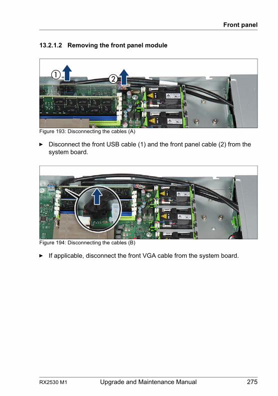
RX2530 M1 Upgrade and Maintenance Manual 275
Front panel
13.2.1.2 Removing the front panel module
Figure 193: Disconnecting the cables (A)
Ê Disconnect the front USB cable (1) and the front panel cable (2) from the system board.
Figure 194: Disconnecting the cables (B)
Ê If applicable, disconnect the front VGA cable from the system board.
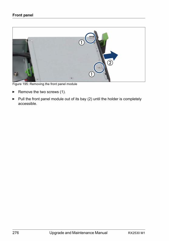
276 Upgrade and Maintenance Manual RX2530 M1
Front panel
Figure 195: Removing the front panel module
Ê Remove the two screws (1).
Ê Pull the front panel module out of its bay (2) until the holder is completely accessible.
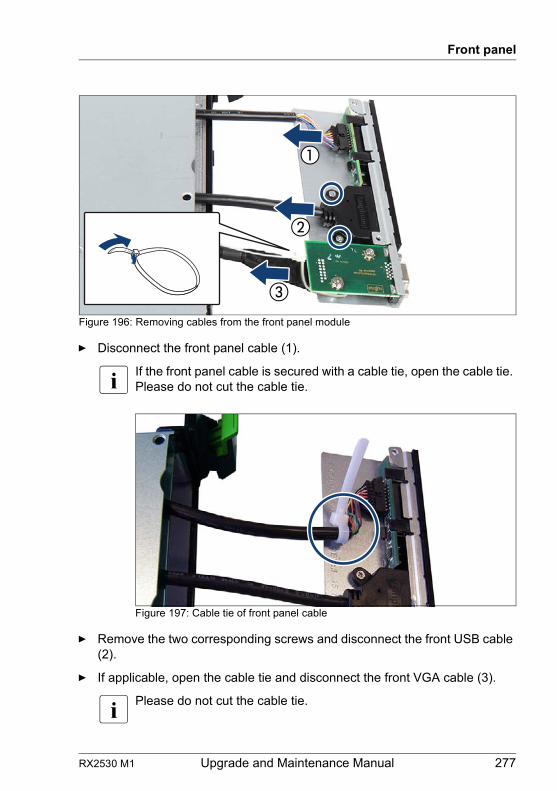
RX2530 M1 Upgrade and Maintenance Manual 277
Front panel
Figure 196: Removing cables from the front panel module
Ê Disconnect the front panel cable (1).
I If the front panel cable is secured with a cable tie, open the cable tie. Please do not cut the cable tie.
Figure 197: Cable tie of front panel cable
Ê Remove the two corresponding screws and disconnect the front USB cable (2).
Ê If applicable, open the cable tie and disconnect the front VGA cable (3).
I Please do not cut the cable tie.
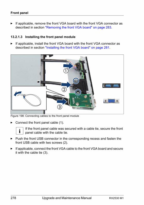
278 Upgrade and Maintenance Manual RX2530 M1
Front panel
Ê If applicable, remove the front VGA board with the front VGA connector as described in section "Removing the front VGA board" on page 283.
13.2.1.3 Installing the front panel module
Ê If applicable, install the front VGA board with the front VGA connector as described in section "Installing the front VGA board" on page 281.
Figure 198: Connecting cables to the front panel module
Ê Connect the front panel cable (1).
I If the front panel cable was secured with a cable tie, secure the front panel cable with the cable tie.
Ê Push the front USB connector in the corresponding recess and fasten the front USB cable with two screws (2).
Ê If applicable, connect the front VGA cable to the front VGA board and secure it with the cable tie (3).
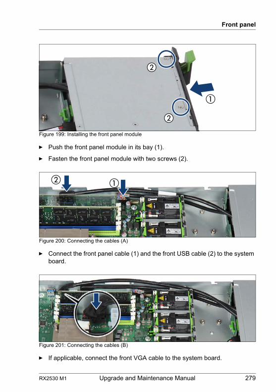
RX2530 M1 Upgrade and Maintenance Manual 279
Front panel
Figure 199: Installing the front panel module
Ê Push the front panel module in its bay (1).
Ê Fasten the front panel module with two screws (2).
Figure 200: Connecting the cables (A)
Ê Connect the front panel cable (1) and the front USB cable (2) to the system board.
Figure 201: Connecting the cables (B)
Ê If applicable, connect the front VGA cable to the system board.
280 Upgrade and Maintenance Manual RX2530 M1
Front panel
13.2.1.4 Concluding steps
Ê "Installing the fan sponges" on page 67 (if applicable)
Ê "Reassembling" on page 54
Ê "Connecting the server to the mains" on page 60
Ê "Enabling SVOM boot watchdog functionality" on page 89
Ê "Using the Chassis ID Prom Tool" on page 98
Ê "Switching on the server" on page 61
Ê "Verifying system information backup / restore" on page 81
Ê "Resuming BitLocker functionality" on page 95
13.3 Front VGA board
13.3.1 Installing the front VGA board
13.3.1.1 Preliminary steps
Ê "Shutting down the server" on page 48
Ê "Disconnecting the server from the mains" on page 49
Ê "Getting access to the component" on page 49
Ê "Removing the front panel module" on page 275
Upgrade and Repair Unit(URU)
Hardware: 10 minutes
Tools: Phillips PH1 / (+) No. 1 screw driver
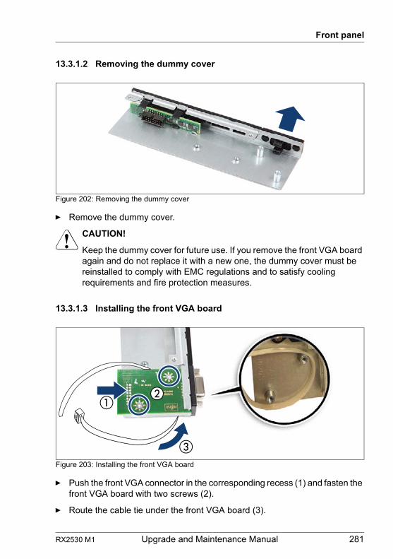
RX2530 M1 Upgrade and Maintenance Manual 281
Front panel
13.3.1.2 Removing the dummy cover
Figure 202: Removing the dummy cover
Ê Remove the dummy cover.
V CAUTION!
Keep the dummy cover for future use. If you remove the front VGA board again and do not replace it with a new one, the dummy cover must be reinstalled to comply with EMC regulations and to satisfy cooling requirements and fire protection measures.
13.3.1.3 Installing the front VGA board
Figure 203: Installing the front VGA board
Ê Push the front VGA connector in the corresponding recess (1) and fasten the front VGA board with two screws (2).
Ê Route the cable tie under the front VGA board (3).
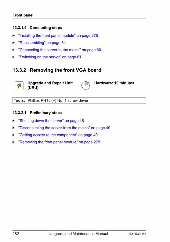
282 Upgrade and Maintenance Manual RX2530 M1
Front panel
13.3.1.4 Concluding steps
Ê "Installing the front panel module" on page 278
Ê "Reassembling" on page 54
Ê "Connecting the server to the mains" on page 60
Ê "Switching on the server" on page 61
13.3.2 Removing the front VGA board
13.3.2.1 Preliminary steps
Ê "Shutting down the server" on page 48
Ê "Disconnecting the server from the mains" on page 49
Ê "Getting access to the component" on page 49
Ê "Removing the front panel module" on page 275
Upgrade and Repair Unit(URU)
Hardware: 10 minutes
Tools: Phillips PH1 / (+) No. 1 screw driver
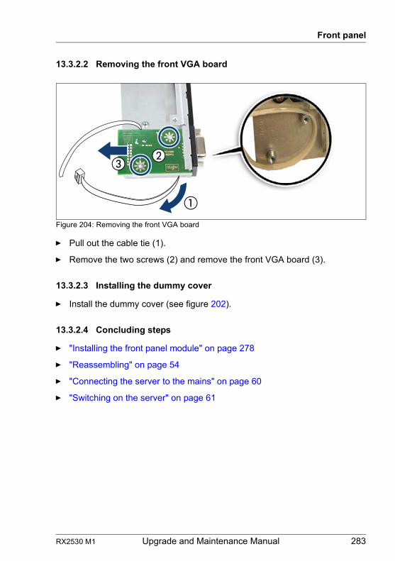
RX2530 M1 Upgrade and Maintenance Manual 283
Front panel
13.3.2.2 Removing the front VGA board
Figure 204: Removing the front VGA board
Ê Pull out the cable tie (1).
Ê Remove the two screws (2) and remove the front VGA board (3).
13.3.2.3 Installing the dummy cover
Ê Install the dummy cover (see figure 202).
13.3.2.4 Concluding steps
Ê "Installing the front panel module" on page 278
Ê "Reassembling" on page 54
Ê "Connecting the server to the mains" on page 60
Ê "Switching on the server" on page 61
284 Upgrade and Maintenance Manual RX2530 M1
Front panel
13.3.3 Replacing the front VGA board
13.3.3.1 Preliminary steps
Ê "Locating the defective server" on page 45
Ê "Shutting down the server" on page 48
Ê "Disconnecting the server from the mains" on page 49
Ê "Getting access to the component" on page 49
Ê "Removing the front panel module" on page 275
13.3.3.2 Removing the defective front VGA board
Ê Remove the front VGA board as described in section "Removing the front VGA board" on page 283.
13.3.3.3 Installing the new front VGA board
Ê Install the front VGA board as described in section "Installing the front VGA board" on page 281.
13.3.3.4 Concluding steps
Ê "Installing the front panel module" on page 278
Ê "Reassembling" on page 54
Ê "Connecting the server to the mains" on page 60
Ê "Switching on the server" on page 61
Upgrade and Repair Unit(URU)
Hardware: 10 minutes
Tools: Phillips PH1 / (+) No. 1 screw driver
RX2530 M1 Upgrade and Maintenance Manual 285
Front panel
13.4 Front panel on QRL (10 x 2.5-inch HDD configuration)
13.4.1 Replacing the front panel on QRL
Note on system information backup / restore
I The front panel contains the Chassis ID EPROM that contains system information like server name and model, housing type, serial number and manufacturing data.To avoid the loss of non-default settings when replacing the system board, a backup copy of important system configuration data is automatically stored from the system board NVRAM to the Chassis ID EPROM. After replacing the system board the backup data is restored from the Chassis ID board to the new system board.
V CAUTION!
For that reason the front panel and system board must not be replaced simultaneously! In this case, restoring the system configuration data on the system board would fail.
13.4.1.1 Preliminary steps
Ê "Locating the defective server" on page 45
Ê "Disabling SVOM boot watchdog functionality" on page 72
Ê "Suspending BitLocker functionality" on page 71
Ê "Shutting down the server" on page 48
Ê "Disconnecting the server from the mains" on page 49
Ê "Getting access to the component" on page 49
Ê "Locating the defective component" on page 47
Field Replaceable Unit(FRU)
Hardware: 10 minutesSoftware: 5 minutes
Tools: Phillips PH1 / (+) No. 1 screw driver
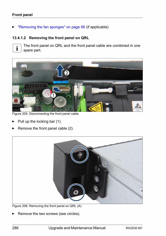
286 Upgrade and Maintenance Manual RX2530 M1
Front panel
Ê "Removing the fan sponges" on page 66 (if applicable)
13.4.1.2 Removing the front panel on QRL
I The front panel on QRL and the front panel cable are combined in one spare part.
Figure 205: Disconnecting the front panel cable
Ê Pull up the locking bar (1).
Ê Remove the front panel cable (2).
Figure 206: Removing the front panel on QRL (A)
Ê Remove the two screws (see circles).
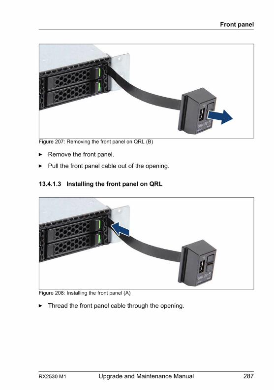
RX2530 M1 Upgrade and Maintenance Manual 287
Front panel
Figure 207: Removing the front panel on QRL (B)
Ê Remove the front panel.
Ê Pull the front panel cable out of the opening.
13.4.1.3 Installing the front panel on QRL
Figure 208: Installing the front panel (A)
Ê Thread the front panel cable through the opening.
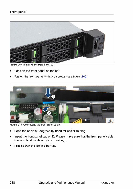
288 Upgrade and Maintenance Manual RX2530 M1
Front panel
Figure 209: Installing the front panel (B)
Ê Position the front panel on the ear.
Ê Fasten the front panel with two screws (see figure 206).
Figure 210: Connecting the front panel cable
Ê Bend the cable 90 degrees by hand for easier routing.
Ê Insert the front panel cable (1). Please make sure that the front panel cable is assembled as shown (blue marking).
Ê Press down the locking bar (2).
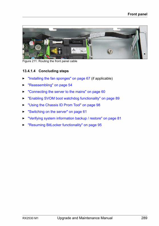
RX2530 M1 Upgrade and Maintenance Manual 289
Front panel
Figure 211: Routing the front panel cable
13.4.1.4 Concluding steps
Ê "Installing the fan sponges" on page 67 (if applicable)
Ê "Reassembling" on page 54
Ê "Connecting the server to the mains" on page 60
Ê "Enabling SVOM boot watchdog functionality" on page 89
Ê "Using the Chassis ID Prom Tool" on page 98
Ê "Switching on the server" on page 61
Ê "Verifying system information backup / restore" on page 81
Ê "Resuming BitLocker functionality" on page 95
290 Upgrade and Maintenance Manual RX2530 M1
Front panel
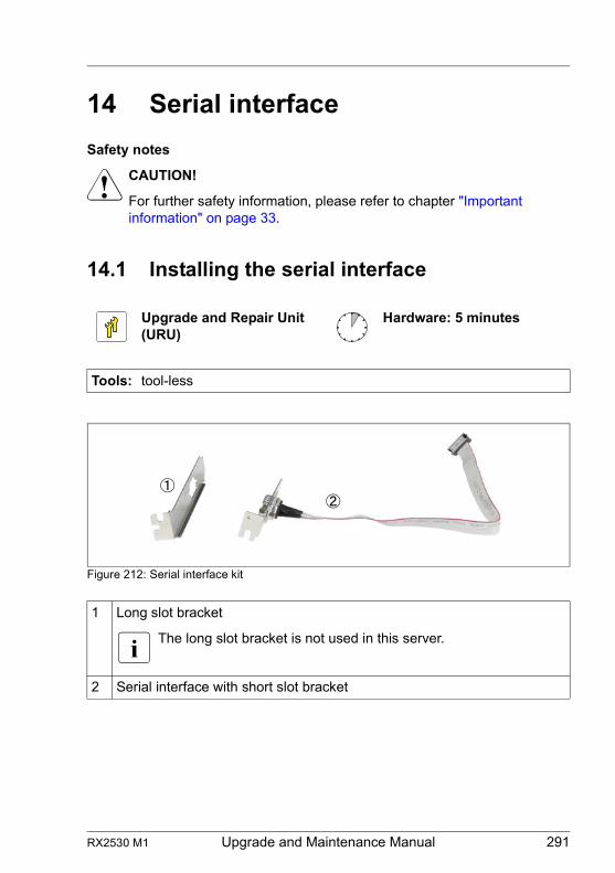
RX2530 M1 Upgrade and Maintenance Manual 291
14 Serial interface
Safety notes
V CAUTION!
For further safety information, please refer to chapter "Important information" on page 33.
14.1 Installing the serial interface
Figure 212: Serial interface kit
Upgrade and Repair Unit(URU)
Hardware: 5 minutes
Tools: tool-less
1 Long slot bracket
I The long slot bracket is not used in this server.
2 Serial interface with short slot bracket
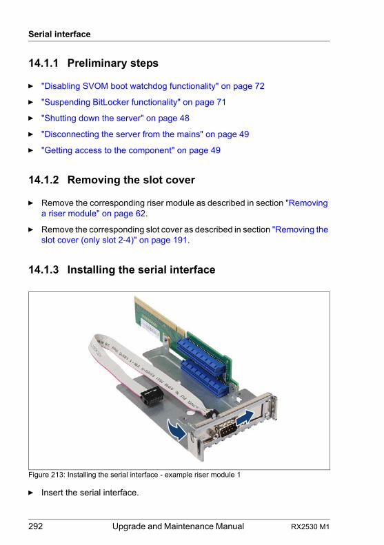
292 Upgrade and Maintenance Manual RX2530 M1
Serial interface
14.1.1 Preliminary steps
Ê "Disabling SVOM boot watchdog functionality" on page 72
Ê "Suspending BitLocker functionality" on page 71
Ê "Shutting down the server" on page 48
Ê "Disconnecting the server from the mains" on page 49
Ê "Getting access to the component" on page 49
14.1.2 Removing the slot cover
Ê Remove the corresponding riser module as described in section "Removing a riser module" on page 62.
Ê Remove the corresponding slot cover as described in section "Removing the slot cover (only slot 2-4)" on page 191.
14.1.3 Installing the serial interface
Figure 213: Installing the serial interface - example riser module 1
Ê Insert the serial interface.
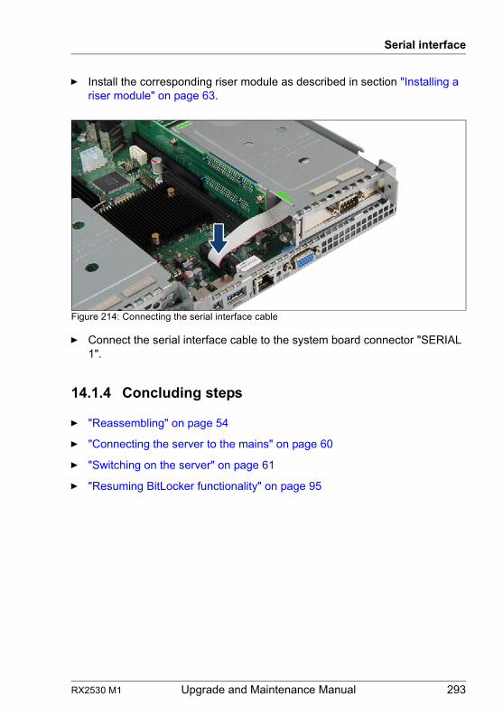
RX2530 M1 Upgrade and Maintenance Manual 293
Serial interface
Ê Install the corresponding riser module as described in section "Installing a riser module" on page 63.
Figure 214: Connecting the serial interface cable
Ê Connect the serial interface cable to the system board connector "SERIAL 1".
14.1.4 Concluding steps
Ê "Reassembling" on page 54
Ê "Connecting the server to the mains" on page 60
Ê "Switching on the server" on page 61
Ê "Resuming BitLocker functionality" on page 95
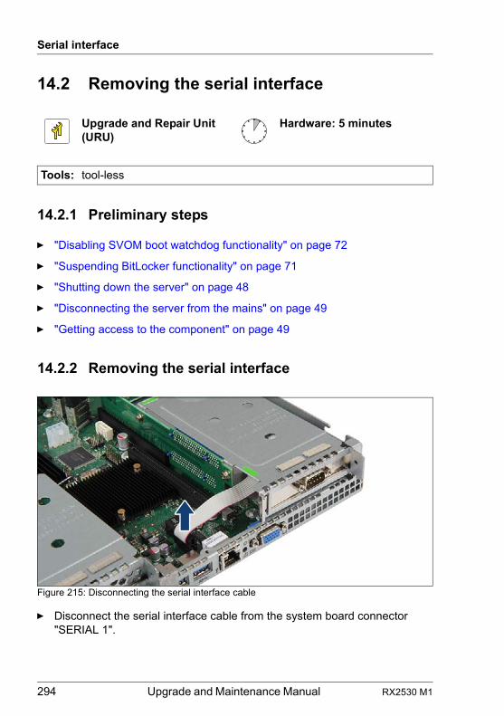
294 Upgrade and Maintenance Manual RX2530 M1
Serial interface
14.2 Removing the serial interface
14.2.1 Preliminary steps
Ê "Disabling SVOM boot watchdog functionality" on page 72
Ê "Suspending BitLocker functionality" on page 71
Ê "Shutting down the server" on page 48
Ê "Disconnecting the server from the mains" on page 49
Ê "Getting access to the component" on page 49
14.2.2 Removing the serial interface
Figure 215: Disconnecting the serial interface cable
Ê Disconnect the serial interface cable from the system board connector "SERIAL 1".
Upgrade and Repair Unit(URU)
Hardware: 5 minutes
Tools: tool-less
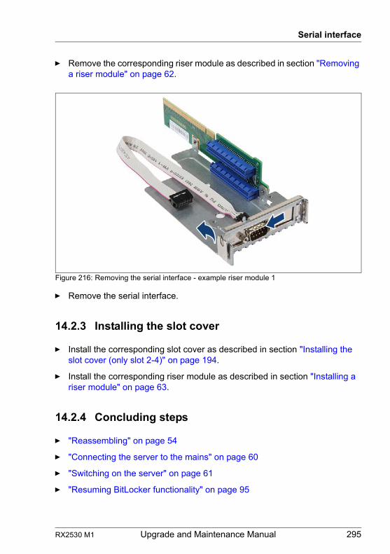
RX2530 M1 Upgrade and Maintenance Manual 295
Serial interface
Ê Remove the corresponding riser module as described in section "Removing a riser module" on page 62.
Figure 216: Removing the serial interface - example riser module 1
Ê Remove the serial interface.
14.2.3 Installing the slot cover
Ê Install the corresponding slot cover as described in section "Installing the slot cover (only slot 2-4)" on page 194.
Ê Install the corresponding riser module as described in section "Installing a riser module" on page 63.
14.2.4 Concluding steps
Ê "Reassembling" on page 54
Ê "Connecting the server to the mains" on page 60
Ê "Switching on the server" on page 61
Ê "Resuming BitLocker functionality" on page 95
296 Upgrade and Maintenance Manual RX2530 M1
Serial interface
14.3 Replacing the serial interface
14.3.1 Preliminary steps
Ê "Disabling SVOM boot watchdog functionality" on page 72
Ê "Suspending BitLocker functionality" on page 71
Ê "Shutting down the server" on page 48
Ê "Disconnecting the server from the mains" on page 49
Ê "Getting access to the component" on page 49
14.3.2 Removing the defective serial interface
Ê Remove the serial interface as described in section "Removing the serial interface" on page 294.
14.3.3 Installing the new serial interface
Ê Install the serial interface as described in section "Installing the serial interface" on page 292.
14.3.4 Concluding steps
Ê "Reassembling" on page 54
Ê "Connecting the server to the mains" on page 60
Ê "Switching on the server" on page 61
Ê "Resuming BitLocker functionality" on page 95
Upgrade and Repair Unit(URU)
Hardware: 5 minutes
Tools: tool-less
RX2530 M1 Upgrade and Maintenance Manual 297
15 System board and components
Safety notes
V CAUTION!
● Devices and components inside the server remain hot after shutdown. After shutting down the server, wait for hot components to cool down before installing or removing internal options.
● Circuit boards and soldered parts of internal options are exposed and can be damaged by static electricity. Always discharge static build-up (e.g. by touching a grounded object) before handling electrostatic-sensitive devices (ESDs).
● Do not touch the circuitry on boards or soldered parts. Hold circuit boards by their metallic areas or edges.
● For further information, please refer to chapter "Important information" on page 33.
15.1 Basic information
This section provides instructions for the system board and the following components:
● CMOS memory (volatile BIOS memory) and the real-time clock are powered by a lithium coin cell (CMOS battery). This cell lasts up to ten years, depending on ambient temperature and use.
If the CMOS battery is depleted or falls below minimum voltage levels, it need to be replaced immediately.
● UFM (USB Flash Module)
The server can be equipped with a USB Flash Module (UFM).
● TPM (Trusted Platform Module)
The system board is optionally equipped with a Trusted Platform Module (TPM). This module enables programs from third party manufacturers to store key information, for example drive encryption using Windows Bitlocker Drive Encryption.
298 Upgrade and Maintenance Manual RX2530 M1
System board and components
● SATA DOM
With the Innodisk Serial ATA Disk on Module (SATADOM) an internal SSD is offered. This SSD can be configured as a boot device or data storage device.
● iRMC microSD card
The iRMC microSD card is necessary for using the embedded Lifecycle Management (eLCM) functionality of the iRMC.
15.2 CMOS battery
15.2.1 Replacing the CMOS battery
Safety notes
V CAUTION!
● The CMOS battery must be replaced with an identical battery or with a battery type recommended by the manufacturer.
● Keep lithium batteries away from children.
● Do not throw batteries into the trash can. Lithium batteries must be disposed of in accordance with local regulations concerning special waste.
● For further safety information, please refer to section "Environmental protection" in the operating manual of your server.
● Ensure to insert the CMOS battery with the positive pole facing up!
Upgrade and Repair Unit(URU)
Hardware: 5 minutes
Tools: tool-less; recommended: tooth pick
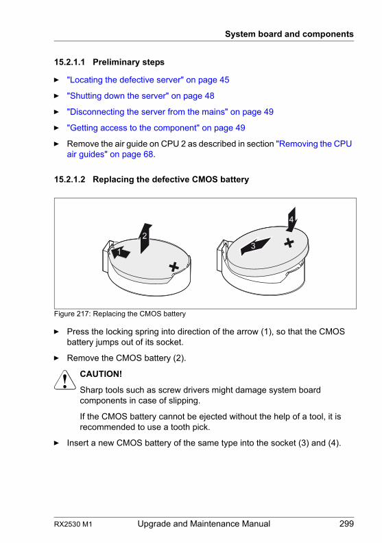
RX2530 M1 Upgrade and Maintenance Manual 299
System board and components
15.2.1.1 Preliminary steps
Ê "Locating the defective server" on page 45
Ê "Shutting down the server" on page 48
Ê "Disconnecting the server from the mains" on page 49
Ê "Getting access to the component" on page 49
Ê Remove the air guide on CPU 2 as described in section "Removing the CPU air guides" on page 68.
15.2.1.2 Replacing the defective CMOS battery
Figure 217: Replacing the CMOS battery
Ê Press the locking spring into direction of the arrow (1), so that the CMOS battery jumps out of its socket.
Ê Remove the CMOS battery (2).
V CAUTION!
Sharp tools such as screw drivers might damage system board components in case of slipping.
If the CMOS battery cannot be ejected without the help of a tool, it is recommended to use a tooth pick.
Ê Insert a new CMOS battery of the same type into the socket (3) and (4).
1
23
4
300 Upgrade and Maintenance Manual RX2530 M1
System board and components
15.2.1.3 Concluding steps
Ê Dispose of the CMOS battery in accordance with local regulations concerning special waste.
Ê Install the air guide on CPU 2 as described in section "Installing the CPU air guides" on page 69.
Ê "Reassembling" on page 54
Ê "Connecting the server to the mains" on page 60
Ê "Switching on the server" on page 61
Ê "Verifying system information backup / restore" on page 81
Ê "Verifying the system time settings" on page 91
15.3 USB Flash Module (UFM)
15.3.1 Installing the UFM
15.3.1.1 Preliminary steps
Ê "Disabling SVOM boot watchdog functionality" on page 72
Ê "Suspending BitLocker functionality" on page 71
Ê "Shutting down the server" on page 48
Ê "Disconnecting the server from the mains" on page 49
Ê "Getting access to the component" on page 49
Ê If applicable, remove the riser module 3 as described in section "Removing a riser module" on page 62.
Field Replaceable Unit(FRU)
Hardware: 5 minutesSoftware: 5 minutes
Tools: tool-less
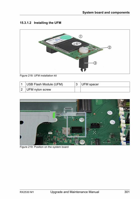
RX2530 M1 Upgrade and Maintenance Manual 301
System board and components
15.3.1.2 Installing the UFM
Figure 218: UFM installation kit
Figure 219: Position on the system board
1 USB Flash Module (UFM) 3 UFM spacer
2 UFM nylon screw
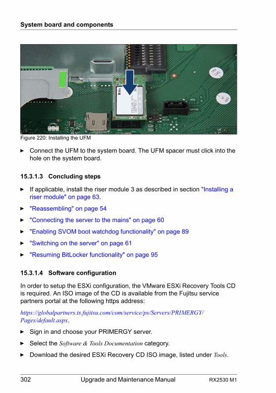
302 Upgrade and Maintenance Manual RX2530 M1
System board and components
Figure 220: Installing the UFM
Ê Connect the UFM to the system board. The UFM spacer must click into the hole on the system board.
15.3.1.3 Concluding steps
Ê If applicable, install the riser module 3 as described in section "Installing a riser module" on page 63.
Ê "Reassembling" on page 54
Ê "Connecting the server to the mains" on page 60
Ê "Enabling SVOM boot watchdog functionality" on page 89
Ê "Switching on the server" on page 61
Ê "Resuming BitLocker functionality" on page 95
15.3.1.4 Software configuration
In order to setup the ESXi configuration, the VMware ESXi Recovery Tools CD is required. An ISO image of the CD is available from the Fujitsu service partners portal at the following https address:
https://globalpartners.ts.fujitsu.com/com/service/ps/Servers/PRIMERGY/Pages/default.aspx.
Ê Sign in and choose your PRIMERGY server.
Ê Select the Software & Tools Documentation category.
Ê Download the desired ESXi Recovery CD ISO image, listed under Tools.
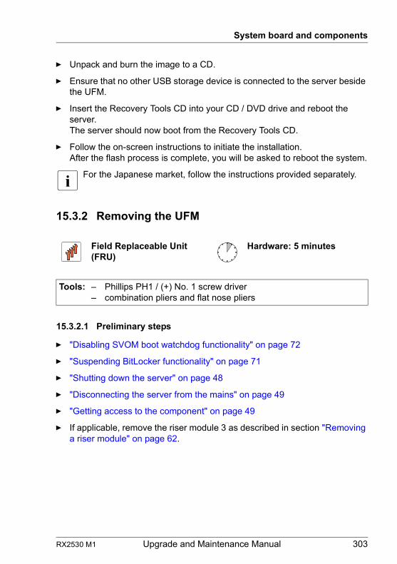
RX2530 M1 Upgrade and Maintenance Manual 303
System board and components
Ê Unpack and burn the image to a CD.
Ê Ensure that no other USB storage device is connected to the server beside the UFM.
Ê Insert the Recovery Tools CD into your CD / DVD drive and reboot the server.The server should now boot from the Recovery Tools CD.
Ê Follow the on-screen instructions to initiate the installation.After the flash process is complete, you will be asked to reboot the system.
I For the Japanese market, follow the instructions provided separately.
15.3.2 Removing the UFM
15.3.2.1 Preliminary steps
Ê "Disabling SVOM boot watchdog functionality" on page 72
Ê "Suspending BitLocker functionality" on page 71
Ê "Shutting down the server" on page 48
Ê "Disconnecting the server from the mains" on page 49
Ê "Getting access to the component" on page 49
Ê If applicable, remove the riser module 3 as described in section "Removing a riser module" on page 62.
Field Replaceable Unit(FRU)
Hardware: 5 minutes
Tools: – Phillips PH1 / (+) No. 1 screw driver– combination pliers and flat nose pliers
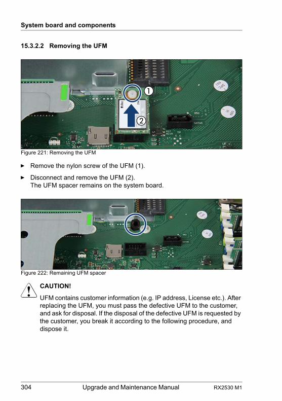
304 Upgrade and Maintenance Manual RX2530 M1
System board and components
15.3.2.2 Removing the UFM
Figure 221: Removing the UFM
Ê Remove the nylon screw of the UFM (1).
Ê Disconnect and remove the UFM (2).The UFM spacer remains on the system board.
Figure 222: Remaining UFM spacer
V CAUTION!
UFM contains customer information (e.g. IP address, License etc.). After replacing the UFM, you must pass the defective UFM to the customer, and ask for disposal. If the disposal of the defective UFM is requested by the customer, you break it according to the following procedure, and dispose it.
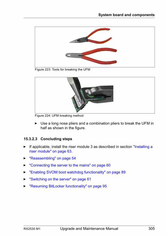
RX2530 M1 Upgrade and Maintenance Manual 305
System board and components
Figure 223: Tools for breaking the UFM
Figure 224: UFM breaking method
Ê Use a long nose pliers and a combination pliers to break the UFM in half as shown in the figure.
15.3.2.3 Concluding steps
Ê If applicable, install the riser module 3 as described in section "Installing a riser module" on page 63.
Ê "Reassembling" on page 54
Ê "Connecting the server to the mains" on page 60
Ê "Enabling SVOM boot watchdog functionality" on page 89
Ê "Switching on the server" on page 61
Ê "Resuming BitLocker functionality" on page 95
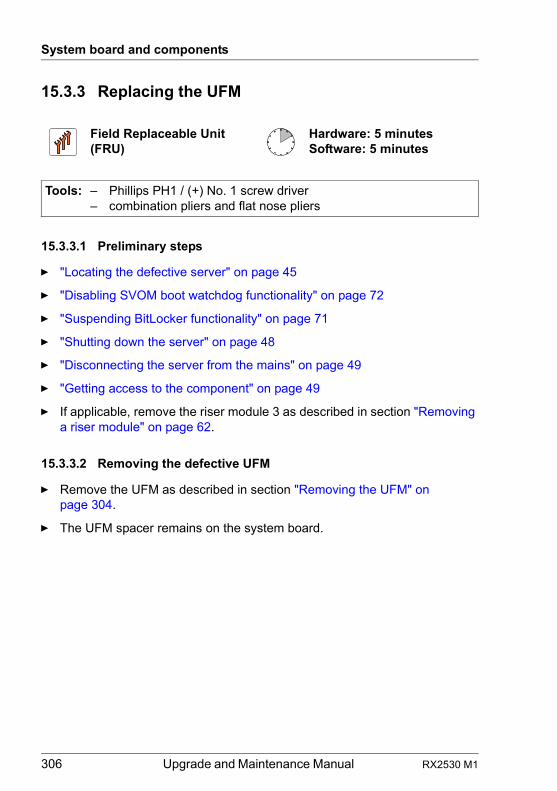
306 Upgrade and Maintenance Manual RX2530 M1
System board and components
15.3.3 Replacing the UFM
15.3.3.1 Preliminary steps
Ê "Locating the defective server" on page 45
Ê "Disabling SVOM boot watchdog functionality" on page 72
Ê "Suspending BitLocker functionality" on page 71
Ê "Shutting down the server" on page 48
Ê "Disconnecting the server from the mains" on page 49
Ê "Getting access to the component" on page 49
Ê If applicable, remove the riser module 3 as described in section "Removing a riser module" on page 62.
15.3.3.2 Removing the defective UFM
Ê Remove the UFM as described in section "Removing the UFM" on page 304.
Ê The UFM spacer remains on the system board.
Field Replaceable Unit(FRU)
Hardware: 5 minutesSoftware: 5 minutes
Tools: – Phillips PH1 / (+) No. 1 screw driver– combination pliers and flat nose pliers
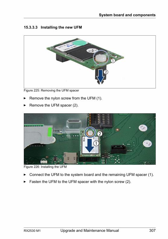
RX2530 M1 Upgrade and Maintenance Manual 307
System board and components
15.3.3.3 Installing the new UFM
Figure 225: Removing the UFM spacer
Ê Remove the nylon screw from the UFM (1).
Ê Remove the UFM spacer (2).
Figure 226: Installing the UFM
Ê Connect the UFM to the system board and the remaining UFM spacer (1).
Ê Fasten the UFM to the UFM spacer with the nylon screw (2).
308 Upgrade and Maintenance Manual RX2530 M1
System board and components
15.3.3.4 Concluding steps
Ê If applicable, install the riser module 3 as described in section "Installing a riser module" on page 63.
Ê "Reassembling" on page 54
Ê "Connecting the server to the mains" on page 60
Ê "Enabling SVOM boot watchdog functionality" on page 89
Ê "Switching on the server" on page 61
Ê "Resuming BitLocker functionality" on page 95
15.3.3.5 Software configuration
In order to setup the ESXi configuration, the VMware ESXi Recovery Tools CD is required. An ISO image of the CD is available from the Fujitsu service partners portal at the following https address:
https://globalpartners.ts.fujitsu.com/com/service/ps/Servers/PRIMERGY/Pages/default.aspx.
Ê Sign in and choose your PRIMERGY server.
Ê Select the Software & Tools Documentation category.
Ê Download the desired ESXi Recovery CD ISO image, listed under Tools.
Ê Unpack and burn the image to a CD.
Ê Ensure that no other USB storage device is connected to the server beside the UFM.
Ê Insert the Recovery Tools CD into your CD / DVD drive and reboot the server.The server should now boot from the Recovery Tools CD.
Ê Follow the on-screen instructions to initiate the installation.After the flash process is complete, you will be asked to reboot the system.
I For the Japanese market, follow the instructions provided separately.
RX2530 M1 Upgrade and Maintenance Manual 309
System board and components
15.4 Trusted Platform Module (TPM)
15.4.1 Installing the TPM
15.4.1.1 Preliminary steps
Ê "Suspending BitLocker functionality" on page 71
Ê "Shutting down the server" on page 48
Ê "Disconnecting the server from the mains" on page 49
Ê "Getting access to the component" on page 49
Ê Remove the riser module 2 as described in section "Removing a riser module" on page 62.
Field Replaceable Unit(FRU)
Hardware: 5 minutesSoftware: 5 minutes
Tools: – Bit screw driver– TPM bit insert (*)
(*) For the Japanese market:
– TPM module fixing tool (S26361-F3552-L909)
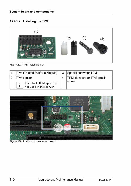
310 Upgrade and Maintenance Manual RX2530 M1
System board and components
15.4.1.2 Installing the TPM
Figure 227: TPM installation kit
Figure 228: Position on the system board
1 TPM (Trusted Platform Module) 3 Special screw for TPM
2 TPM spacer
I The black TPM spacer is not used in this server.
4 TPM bit insert for TPM special screw
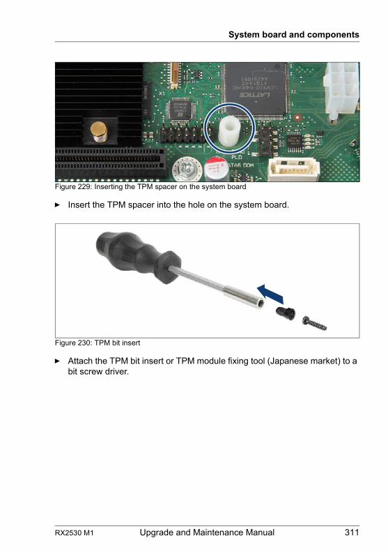
RX2530 M1 Upgrade and Maintenance Manual 311
System board and components
Figure 229: Inserting the TPM spacer on the system board
Ê Insert the TPM spacer into the hole on the system board.
Figure 230: TPM bit insert
Ê Attach the TPM bit insert or TPM module fixing tool (Japanese market) to a bit screw driver.
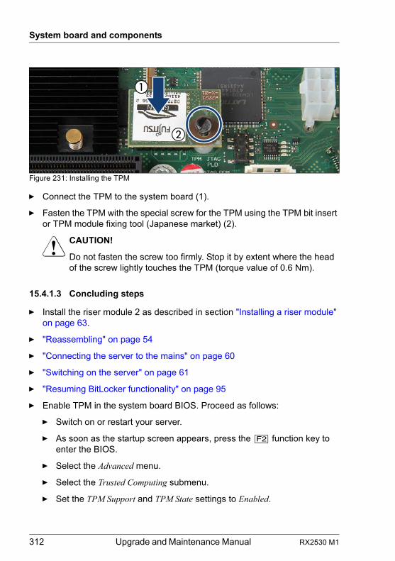
312 Upgrade and Maintenance Manual RX2530 M1
System board and components
Figure 231: Installing the TPM
Ê Connect the TPM to the system board (1).
Ê Fasten the TPM with the special screw for the TPM using the TPM bit insert or TPM module fixing tool (Japanese market) (2).
V CAUTION!
Do not fasten the screw too firmly. Stop it by extent where the head of the screw lightly touches the TPM (torque value of 0.6 Nm).
15.4.1.3 Concluding steps
Ê Install the riser module 2 as described in section "Installing a riser module" on page 63.
Ê "Reassembling" on page 54
Ê "Connecting the server to the mains" on page 60
Ê "Switching on the server" on page 61
Ê "Resuming BitLocker functionality" on page 95
Ê Enable TPM in the system board BIOS. Proceed as follows:
Ê Switch on or restart your server.
Ê As soon as the startup screen appears, press the [F2] function key to enter the BIOS.
Ê Select the Advanced menu.
Ê Select the Trusted Computing submenu.
Ê Set the TPM Support and TPM State settings to Enabled.
RX2530 M1 Upgrade and Maintenance Manual 313
System board and components
Ê Under Pending TPM operation, select the desired TPM operation mode.
Ê Save your changes and exit the BIOS.
I For detailed information on how to access the BIOS and modify settings, refer to the corresponding BIOS Setup Utility reference manual.
15.4.2 Removing the TPM
V CAUTION!
Advise your contact persons that they must provide you with TPM backup copies. For security reasons, the TPM must be restored/re-saved by the customer. After installing a new system board, the TPM must be enabled. You may not clear the TPM data.If the contact persons DO NOT have a backup copy available, inform them that removing the TPM will cause to lose all data.
15.4.2.1 Preliminary steps
Before removing the TPM board, perform the following steps:
Ê Before removing the TPM board, it is necessary to remove BitLocker-protection from the computer and to decrypt the volume.
Field Replaceable Unit(FRU)
Hardware: 30 minutes
Tools: Removing the system board:
– Phillips PH2 / (+) No. 2 screw driver
Removing the TPM:
– Bit screw driver– flat nose pliers– TPM bit insert (*)
(*) For the Japanese market:
– TPM module fixing tool (S26361-F3552-L909)
314 Upgrade and Maintenance Manual RX2530 M1
System board and components
Ask the system administrator to turn off BitLocker-protection using the BitLocker setup wizard available either from the Control Panel or Windows Explorer:
Ê Open Bitlocker Drive Encryption by clicking the Start button, clicking Control Panel, clicking Security, and then clicking Bitlocker Drive Encryption.
I Administrator permission required If you are prompted for an administrator password or confirmation, type the password or provide confirmation.
Ê To turn off BitLocker and decrypt the volume, click Turn Off BitLocker, and then click Decrypt the volume.
I Decrypting the volume may be time-consuming. By decrypting the volume, all of the information stored on that computer is decrypted.
For further information on how to disable BitLocker drive encryption, please refer to the Microsoft Knowledge Base.
Fujitsu service partners will find additional information (also available in Japanese) on the Fujitsu Extranet web pages.
Ê Disable TPM in the system board BIOS. Proceed as follows:
Ê Switch on or restart your server.
Ê As soon as the startup screen appears, press the [F2] function key to enter the BIOS.
Ê Select the Advanced menu.
Ê Select the Trusted Computing submenu.
Ê Set the TPM Support and TPM State settings to Disabled.
Ê Save your changes and exit the BIOS.
I For detailed information on how to access the BIOS and modify settings, refer to the corresponding BIOS Setup Utility reference manual.
Ê "Suspending BitLocker functionality" on page 71
Ê "Shutting down the server" on page 48
Ê "Disconnecting the server from the mains" on page 49
Ê "Getting access to the component" on page 49
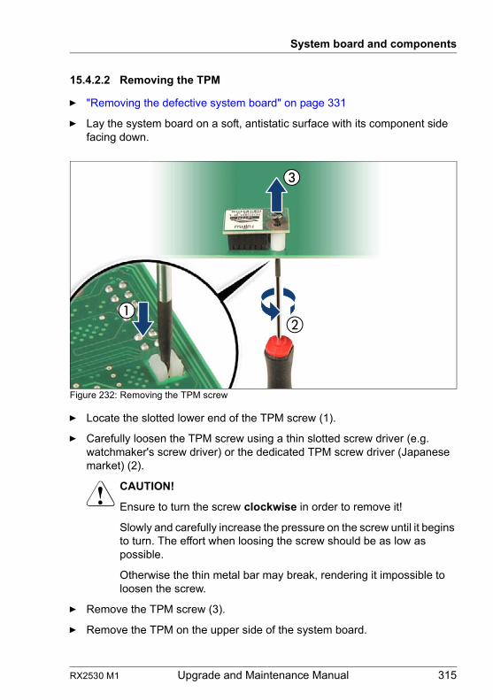
RX2530 M1 Upgrade and Maintenance Manual 315
System board and components
15.4.2.2 Removing the TPM
Ê "Removing the defective system board" on page 331
Ê Lay the system board on a soft, antistatic surface with its component side facing down.
Figure 232: Removing the TPM screw
Ê Locate the slotted lower end of the TPM screw (1).
Ê Carefully loosen the TPM screw using a thin slotted screw driver (e.g. watchmaker's screw driver) or the dedicated TPM screw driver (Japanese market) (2).
V CAUTION!
Ensure to turn the screw clockwise in order to remove it!
Slowly and carefully increase the pressure on the screw until it begins to turn. The effort when loosing the screw should be as low as possible.
Otherwise the thin metal bar may break, rendering it impossible to loosen the screw.
Ê Remove the TPM screw (3).
Ê Remove the TPM on the upper side of the system board.
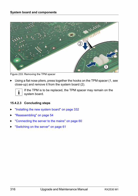
316 Upgrade and Maintenance Manual RX2530 M1
System board and components
Figure 233: Removing the TPM spacer
Ê Using a flat nose pliers, press together the hooks on the TPM spacer (1, see close-up) and remove it from the system board (2).
I If the TPM is to be replaced, the TPM spacer may remain on the system board.
15.4.2.3 Concluding steps
Ê "Installing the new system board" on page 332
Ê "Reassembling" on page 54
Ê "Connecting the server to the mains" on page 60
Ê "Switching on the server" on page 61
RX2530 M1 Upgrade and Maintenance Manual 317
System board and components
15.4.3 Replacing the TPM
V CAUTION!
Advise your contact persons that they must provide you with TPM backup copies. For security reasons, the TPM must be restored/re-saved by the customer. After installing a new system board, the TPM must be enabled. You may not clear the TPM data.
If the contact persons DO NOT have a backup copy available, inform them that replacing the TPM board will cause to lose all data.
15.4.3.1 Preliminary steps
Ê "Locating the defective server" on page 45
Ê "Suspending BitLocker functionality" on page 71
Ê "Shutting down the server" on page 48
Ê "Disconnecting the server from the mains" on page 49
Ê "Getting access to the component" on page 49
Ê "Removing the defective system board" on page 331
Field Replaceable Unit(FRU)
Hardware: 30 minutes
Tools: Removing the system board:
– Phillips PH2 / (+) No. 2 screw driver
Replacing the TPM:
– Bit screw driver– TPM bit insert (*)
– flat nose pliers– thin slotted screw driver (2 x 0.4 mm) (*)
(*) For the Japanese market:
– Dedicated TPM screw driver (CWZ8291A)– TPM module fixing tool (S26361-F3552-L909)
318 Upgrade and Maintenance Manual RX2530 M1
System board and components
15.4.3.2 Removing the defective TPM
Ê Remove the TPM as described in section "Removing the TPM" on page 313.
Ê Leave the TPM spacer on the system board when removing the defective TPM.
15.4.3.3 Installing the new TPM
I The TPM spacer is already present on the system board.
Ê Install the TPM as described in section "Installing the TPM" on page 310.
15.4.3.4 Concluding steps
Ê Reinstall the system board as described in section "Installing the new system board" on page 332
Ê "Reassembling" on page 54
Ê "Connecting the server to the mains" on page 60
Ê "Switching on the server" on page 61
Ê "Resuming BitLocker functionality" on page 95
I You can find information on configuring the TPM in the corresponding BIOS Setup Utility reference manual.
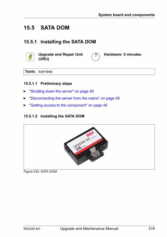
RX2530 M1 Upgrade and Maintenance Manual 319
System board and components
15.5 SATA DOM
15.5.1 Installing the SATA DOM
15.5.1.1 Preliminary steps
Ê "Shutting down the server" on page 48
Ê "Disconnecting the server from the mains" on page 49
Ê "Getting access to the component" on page 49
15.5.1.2 Installing the SATA DOM
Figure 234: SATA DOM
Upgrade and Repair Unit(URU)
Hardware: 5 minutes
Tools: tool-less
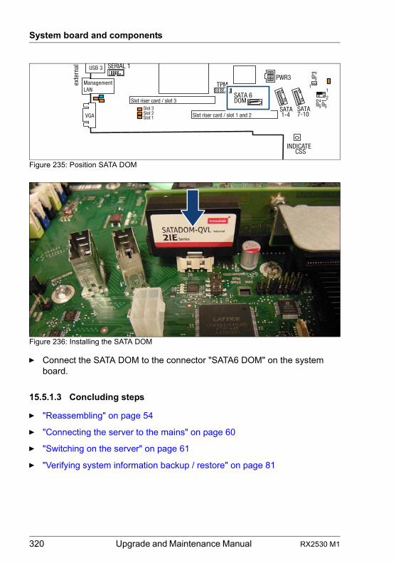
320 Upgrade and Maintenance Manual RX2530 M1
System board and components
Figure 235: Position SATA DOM
Figure 236: Installing the SATA DOM
Ê Connect the SATA DOM to the connector "SATA6 DOM" on the system board.
15.5.1.3 Concluding steps
Ê "Reassembling" on page 54
Ê "Connecting the server to the mains" on page 60
Ê "Switching on the server" on page 61
Ê "Verifying system information backup / restore" on page 81
exte
rnal
INDICATECSS
TPM
VGA
USB 3
ManagementLAN
Slot riser card / slot 1 and 2
JP3
SATA 1-4
Slot riser card / slot 3Slot 3
SERIAL 1
Slot 2Slot 1
PWR3
SATA7-10
SATA 6 DOM
JP2
JP1
11
2
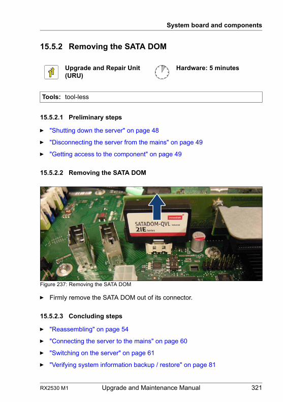
RX2530 M1 Upgrade and Maintenance Manual 321
System board and components
15.5.2 Removing the SATA DOM
15.5.2.1 Preliminary steps
Ê "Shutting down the server" on page 48
Ê "Disconnecting the server from the mains" on page 49
Ê "Getting access to the component" on page 49
15.5.2.2 Removing the SATA DOM
Figure 237: Removing the SATA DOM
Ê Firmly remove the SATA DOM out of its connector.
15.5.2.3 Concluding steps
Ê "Reassembling" on page 54
Ê "Connecting the server to the mains" on page 60
Ê "Switching on the server" on page 61
Ê "Verifying system information backup / restore" on page 81
Upgrade and Repair Unit(URU)
Hardware: 5 minutes
Tools: tool-less
322 Upgrade and Maintenance Manual RX2530 M1
System board and components
15.5.3 Replacing the SATA DOM
15.5.3.1 Preliminary steps
Ê "Locating the defective server" on page 45
Ê "Shutting down the server" on page 48
Ê "Disconnecting the server from the mains" on page 49
Ê "Getting access to the component" on page 49
15.5.3.2 Replacing the SATA DOM
Ê Remove the defective SATA DOM as described in section "Removing the SATA DOM" on page 321.
Ê Install the new SATA DOM as described in section "Installing the SATA DOM" on page 319.
15.5.3.3 Concluding steps
Ê "Reassembling" on page 54
Ê "Connecting the server to the mains" on page 60
Ê "Switching on the server" on page 61
Ê "Verifying system information backup / restore" on page 81
Upgrade and Repair Unit(URU)
Hardware: 5 minutes
Tools: tool-less
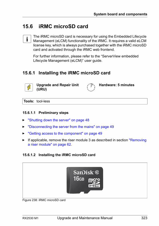
RX2530 M1 Upgrade and Maintenance Manual 323
System board and components
15.6 iRMC microSD card
I The iRMC microSD card is necessary for using the Embedded Lifecycle Management (eLCM) functionality of the iRMC. It requires a valid eLCM license key, which is always purchased together with the iRMC microSD card and activated through the iRMC web frontend.
For further information, please refer to the “ServerView embedded Lifecycle Management (eLCM)” user guide.
15.6.1 Installing the iRMC microSD card
15.6.1.1 Preliminary steps
Ê "Shutting down the server" on page 48
Ê "Disconnecting the server from the mains" on page 49
Ê "Getting access to the component" on page 49
Ê If applicable, remove the riser module 3 as described in section "Removing a riser module" on page 62.
15.6.1.2 Installing the iRMC microSD card
Figure 238: iRMC microSD card
Upgrade and Repair Unit(URU)
Hardware: 5 minutes
Tools: tool-less
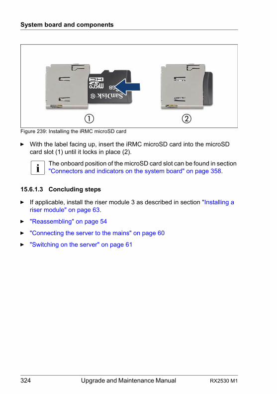
324 Upgrade and Maintenance Manual RX2530 M1
System board and components
Figure 239: Installing the iRMC microSD card
Ê With the label facing up, insert the iRMC microSD card into the microSD card slot (1) until it locks in place (2).
I The onboard position of the microSD card slot can be found in section "Connectors and indicators on the system board" on page 358.
15.6.1.3 Concluding steps
Ê If applicable, install the riser module 3 as described in section "Installing a riser module" on page 63.
Ê "Reassembling" on page 54
Ê "Connecting the server to the mains" on page 60
Ê "Switching on the server" on page 61
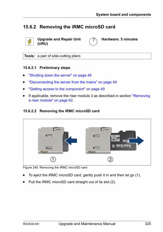
RX2530 M1 Upgrade and Maintenance Manual 325
System board and components
15.6.2 Removing the iRMC microSD card
15.6.2.1 Preliminary steps
Ê "Shutting down the server" on page 48
Ê "Disconnecting the server from the mains" on page 49
Ê "Getting access to the component" on page 49
Ê If applicable, remove the riser module 3 as described in section "Removing a riser module" on page 62.
15.6.2.2 Removing the iRMC microSD card
Figure 240: Removing the iRMC microSD card
Ê To eject the iRMC microSD card, gently push it in and then let go (1).
Ê Pull the iRMC microSD card straight out of its slot (2).
Upgrade and Repair Unit(URU)
Hardware: 5 minutes
Tools: a pair of side-cutting pliers
326 Upgrade and Maintenance Manual RX2530 M1
System board and components
Destroying the defective iRMC microSD card
V CAUTION!
The iRMC microSD card contains customer information. After replacing the iRMC microSD card, hand the defective card over to the customer. If the customer requests disposal of the defective iRMC microSD card, proceed as follows:
Ê Using a pair of side-cutting pliers, cut the iRMC microSD card in half.
15.6.2.3 Concluding steps
Ê If applicable, install the riser module 3 as described in section "Installing a riser module" on page 63.
Ê "Reassembling" on page 54
Ê "Connecting the server to the mains" on page 60
Ê "Switching on the server" on page 61
15.6.3 Replacing the iRMC microSD card
15.6.3.1 Preliminary steps
Ê "Locating the defective server" on page 45
Ê "Shutting down the server" on page 48
Ê "Disconnecting the server from the mains" on page 49
Ê "Getting access to the component" on page 49
Ê If applicable, remove the riser module 3 as described in section "Removing a riser module" on page 62.
Upgrade and Repair Unit(URU)
Hardware: 5 minutes
Tools: a pair of side-cutting pliers
RX2530 M1 Upgrade and Maintenance Manual 327
System board and components
15.6.3.2 Replacing the iRMC microSD card
Ê Remove the defective iRMC microSD card as described in section "Removing the iRMC microSD card" on page 325.
Ê Install the new iRMC microSD card as described in section "Installing the iRMC microSD card" on page 323.
15.6.3.3 Concluding steps
Ê If applicable, install the riser module 3 as described in section "Installing a riser module" on page 63.
Ê "Reassembling" on page 54
Ê "Connecting the server to the mains" on page 60
Ê "Switching on the server" on page 61
328 Upgrade and Maintenance Manual RX2530 M1
System board and components
15.7 System board
15.7.1 Replacing the system board
Note on TPM
I The system board can be equipped with an optional TPM (Trusted Platform Module). This module enables third party programs to store key information (e. g. drive encryption using Windows Bitlocker Drive Encryption).
If the customer is using TPM functionality, the TPM has to be removed from the defective system board and connected to the new system board. For a detailed description, please refer to section "Replacing the TPM" on page 317.
The TPM is activated in the system BIOS.
Field Replaceable Unit(FRU)
Hardware: 40 minutesSoftware: 20 minutes
Tools: Replacing the system board:– Phillips PH2 / (+) No. 2 screw driver– Magnifying glass for inspecting processor socket springs
(recommended)
Replacing the TPM:– Bit screw driver– flat nose pliers– TPM bit insert (*)
– thin slotted screw driver (2 x 0.4 mm) (*)
(*) For the Japanese market:– Dedicated TPM screw driver (CWZ8291A)– TPM module fixing tool (S26361-F3552-L909)
If an UFM is installed:– Phillips PH1 / (+) No. 1 screw driver
If a DynamicLoM module is installed:– Phillips PH1 / (+) No. 1 screw driver– hexagon screw driver 5mm
RX2530 M1 Upgrade and Maintenance Manual 329
System board and components
V CAUTION!
– Before replacing the system board, ask the customer whether TPM functionality is used.
– If the customer is using TPM functionality, remove the TPM from the old system board and install it on the new system board.
Advise your contact persons that they must provide you with TPM backup copies. For security reasons, the TPM must be restored / re-saved by the customer. After installing a new system board the TPM must be enabled. You may not clear the TPM data.If the contact persons DO NOT have a backup copy available, inform them that replacing the TPM board will cause to lose all data.
Note on system information backup / restore
I The front panel contains the Chassis ID EPROM that contains system information like server name and model, housing type, serial number and manufacturing data.
To avoid the loss of non-default settings when replacing the system board, a backup copy of important system configuration data is automatically stored from the system board NVRAM to the Chassis ID EPROM. After replacing the system board the backup data is restored from the Chassis ID board to the new system board.
V CAUTION!
For that reason the front panel and system board must not be replaced simultaneously! In this case, restoring the system configuration data on the system board would fail.
Note on network settings recovery
I When replacing network controllers or the system board, network configuration settings in the operating system will be lost and replaced by default values. This applies to all static IP address and LAN teaming configurations.Ensure to note down your current network settings before replacing a network controller or the system board.
330 Upgrade and Maintenance Manual RX2530 M1
System board and components
15.7.1.1 Preliminary steps
Ê "Locating the defective server" on page 45
Ê "Note on network settings recovery" on page 329
Ê "Disabling SVOM boot watchdog functionality" on page 72
Ê "Suspending BitLocker functionality" on page 71
Ê "Shutting down the server" on page 48
Ê "Disconnecting the server from the mains" on page 49
Ê Disconnect all external cables.
Ê "Getting access to the component" on page 49
Ê Remove all power supply units, see section "Removing a power supply unit" on page 111.
Ê Remove all memory modules, see section "Removing a memory module" on page 235.
I Before removing the memory modules, take a note on the installation slot number for each memory module. Make sure that you reinstall the memory modules in the slot they were located before the replacement.
Ê Remove the heat sink, see section "Removing the heat sink" on page 252.
Ê Remove all fans, see section "Removing the defective fan module" on page 158.
Ê Remove all expansion cards, see section "Expansion cards and riser cards" on page 189.
I Before removing the expansion cards, take a note on the installation slot number for each card. Make sure that you reinstall the card in the slot it was located before the replacement.
Ê Remove the DynamicLoM module (if applicable), see section "DynamicLoM modules" on page 179.
Ê Remove the UFM (if applicable), see section "Removing the defective UFM" on page 306.
I Remove the UFM spacer from the defective system board and fasten it with the UFM screw to the UFM board.
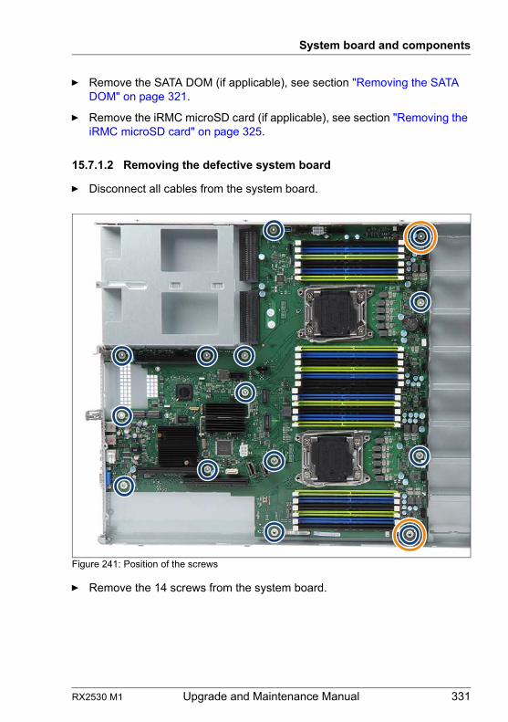
RX2530 M1 Upgrade and Maintenance Manual 331
System board and components
Ê Remove the SATA DOM (if applicable), see section "Removing the SATA DOM" on page 321.
Ê Remove the iRMC microSD card (if applicable), see section "Removing the iRMC microSD card" on page 325.
15.7.1.2 Removing the defective system board
Ê Disconnect all cables from the system board.
Figure 241: Position of the screws
Ê Remove the 14 screws from the system board.
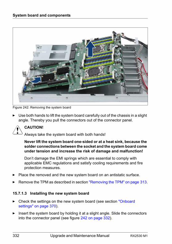
332 Upgrade and Maintenance Manual RX2530 M1
System board and components
Figure 242: Removing the system board
Ê Use both hands to lift the system board carefully out of the chassis in a slight angle. Thereby you pull the connectors out of the connector panel.
V CAUTION!
Always take the system board with both hands!
Never lift the system board one-sided or at a heat sink, because the solder connections between the socket and the system board come under tension and increase the risk of damage and malfunction!
Don’t damage the EMI springs which are essential to comply with applicable EMC regulations and satisfy cooling requirements and fire protection measures.
Ê Place the removed and the new system board on an antistatic surface.
Ê Remove the TPM as described in section "Removing the TPM" on page 313.
15.7.1.3 Installing the new system board
Ê Check the settings on the new system board (see section "Onboard settings" on page 370).
Ê Insert the system board by holding it at a slight angle. Slide the connectors into the connector panel (see figure 242 on page 332).
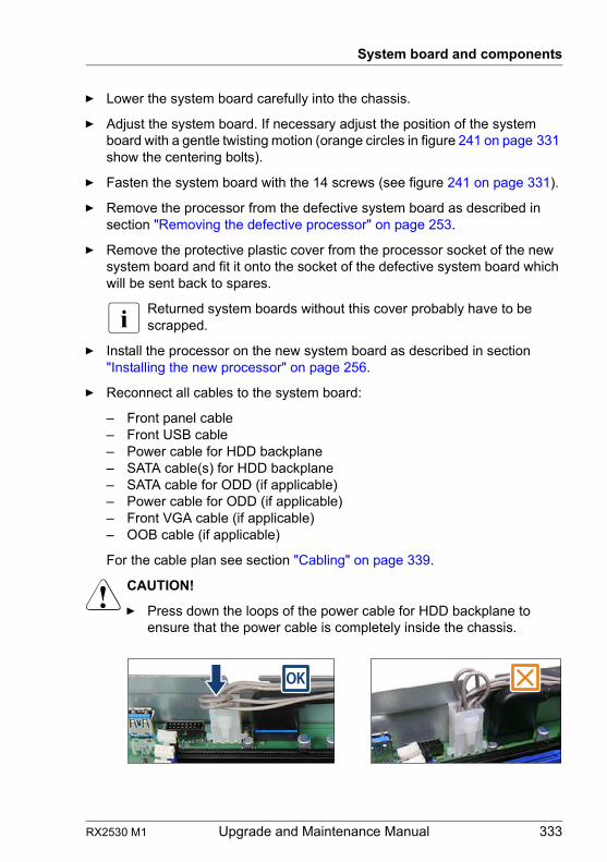
RX2530 M1 Upgrade and Maintenance Manual 333
System board and components
Ê Lower the system board carefully into the chassis.
Ê Adjust the system board. If necessary adjust the position of the system board with a gentle twisting motion (orange circles in figure 241 on page 331 show the centering bolts).
Ê Fasten the system board with the 14 screws (see figure 241 on page 331).
Ê Remove the processor from the defective system board as described in section "Removing the defective processor" on page 253.
Ê Remove the protective plastic cover from the processor socket of the new system board and fit it onto the socket of the defective system board which will be sent back to spares.
I Returned system boards without this cover probably have to be scrapped.
Ê Install the processor on the new system board as described in section "Installing the new processor" on page 256.
Ê Reconnect all cables to the system board:
– Front panel cable– Front USB cable– Power cable for HDD backplane– SATA cable(s) for HDD backplane– SATA cable for ODD (if applicable)– Power cable for ODD (if applicable)– Front VGA cable (if applicable)– OOB cable (if applicable)
For the cable plan see section "Cabling" on page 339.
V CAUTION!
Ê Press down the loops of the power cable for HDD backplane to ensure that the power cable is completely inside the chassis.
334 Upgrade and Maintenance Manual RX2530 M1
System board and components
15.7.1.4 Concluding steps
Ê "Installing the iRMC microSD card" on page 323 (if applicable)
Ê "Installing the SATA DOM" on page 319 (if applicable)
Ê "Installing the TPM" on page 309 (if applicable)
Ê "Installing the UFM" on page 300 (if applicable)
Ê Install the memory modules, see section "Installing a memory module" on page 233.
I Make sure that you reinstall each memory module in the slot it was located before the replacement.
Ê Install all fans, see section "Installing the new fan module" on page 159.
Ê Install the heat sink, see section "Installing the heat sink" on page 257.
Ê Install the DynamicLoM module (if applicable), see section "DynamicLoM modules" on page 179.
Ê Install all expansion cards, see section "Expansion cards and riser cards" on page 189.
I Make sure that you reinstall each card in the slots it was located before the replacement.
Ê Install all power supply units, see section "Installing a power supply unit" on page 107.
Ê "Reassembling" on page 54
Ê "Connecting the server to the mains" on page 60
Ê Connect all external cables.
Ê "Updating or recovering the system board BIOS and iRMC" on page 79
Ê If applicable, activate TPM functionality in the system BIOS under Security > TPM (Security Chip) Setting > Security Chip. For more information, refer to the corresponding BIOS Setup Utility reference manual.
Ê "Verifying system information backup / restore" on page 81
Ê If customer BIOS settings are not restored automatically, please change the settings manually (using the information collected during "preliminary steps"). If you couldn't determine the BIOS version, ask the customer to reconfigure all BIOS settings and password.
RX2530 M1 Upgrade and Maintenance Manual 335
System board and components
Ê "Verifying the system time settings" on page 91
Ê "Looking up changed MAC / WWN addresses" on page 96
Ê "Updating the NIC configuration file in a Linux environment" on page 93
Ê "Enabling SVOM boot watchdog functionality" on page 89
Ê "Switching on the server" on page 61
Ê "Resuming BitLocker functionality" on page 95
Ê If applicable, reconfigure your network settings in the operation system according to the original configuration of the replaced controller (expansion card or onboard).
I Configuration of network settings should be performed by the customer. For further information, please refer to section "Note on network settings recovery" on page 329.
Ê If applicable, restore LAN teaming configurations as described in section "After replacing the system board" on page 99
336 Upgrade and Maintenance Manual RX2530 M1
System board and components
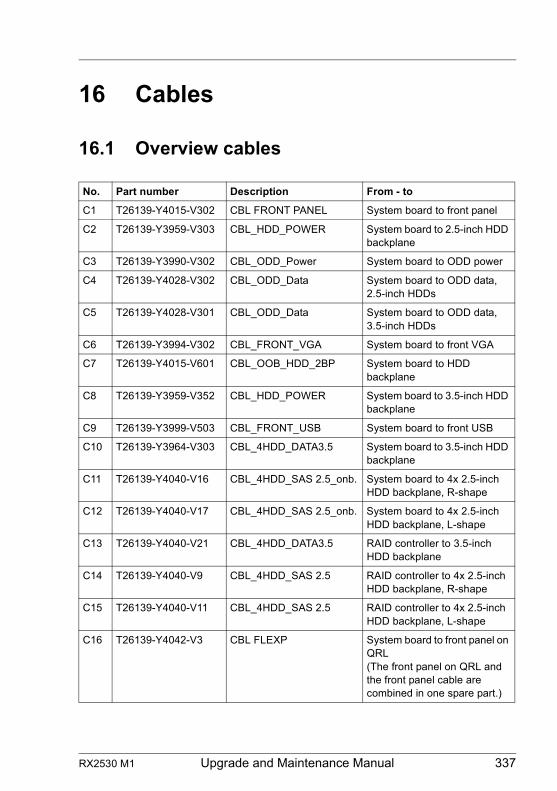
RX2530 M1 Upgrade and Maintenance Manual 337
16 Cables
16.1 Overview cables
No. Part number Description From - to
C1 T26139-Y4015-V302 CBL FRONT PANEL System board to front panel
C2 T26139-Y3959-V303 CBL_HDD_POWER System board to 2.5-inch HDD backplane
C3 T26139-Y3990-V302 CBL_ODD_Power System board to ODD power
C4 T26139-Y4028-V302 CBL_ODD_Data System board to ODD data, 2.5-inch HDDs
C5 T26139-Y4028-V301 CBL_ODD_Data System board to ODD data, 3.5-inch HDDs
C6 T26139-Y3994-V302 CBL_FRONT_VGA System board to front VGA
C7 T26139-Y4015-V601 CBL_OOB_HDD_2BP System board to HDD backplane
C8 T26139-Y3959-V352 CBL_HDD_POWER System board to 3.5-inch HDD backplane
C9 T26139-Y3999-V503 CBL_FRONT_USB System board to front USB
C10 T26139-Y3964-V303 CBL_4HDD_DATA3.5 System board to 3.5-inch HDD backplane
C11 T26139-Y4040-V16 CBL_4HDD_SAS 2.5_onb. System board to 4x 2.5-inch HDD backplane, R-shape
C12 T26139-Y4040-V17 CBL_4HDD_SAS 2.5_onb. System board to 4x 2.5-inch HDD backplane, L-shape
C13 T26139-Y4040-V21 CBL_4HDD_DATA3.5 RAID controller to 3.5-inch HDD backplane
C14 T26139-Y4040-V9 CBL_4HDD_SAS 2.5 RAID controller to 4x 2.5-inch HDD backplane, R-shape
C15 T26139-Y4040-V11 CBL_4HDD_SAS 2.5 RAID controller to 4x 2.5-inch HDD backplane, L-shape
C16 T26139-Y4042-V3 CBL FLEXP System board to front panel on QRL(The front panel on QRL and the front panel cable are combined in one spare part.)
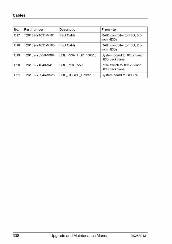
338 Upgrade and Maintenance Manual RX2530 M1
Cables
C17 T26139-Y4031-V101 FBU Cable RAID controller to FBU, 3.5-inch HDDs
C18 T26139-Y4031-V103 FBU Cable RAID controller to FBU, 2.5-inch HDDs
C19 T26139-Y3959-V304 CBL_PWR_HDD_10X2.5 System board to 10x 2.5-inch HDD backplane
C20 T26139-Y4040-V41 CBL_PCIE_550 PCIe switch to 10x 2.5-inch HDD backplane
C21 T26139-Y3946-V525 CBL_GPGPU_Power System board to GPGPU
No. Part number Description From - to
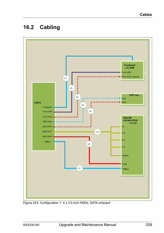
RX2530 M1 Upgrade and Maintenance Manual 339
Cables
16.2 Cabling
Figure 243: Configuration 1: 4 x 3.5-inch HDDs, SATA onboard
SAS BPA3C40157818 4 x 3.5“
P1
P2
P3
P4
PWR
SMBus
SGPIO
D3279
HDD MLC1
Frontpanel
Front USB
Front VGA
ODD Data
ODD PWR
HDD PWR
SMBus
DVD (opt.)
Frontpanel+ 2x USB
Front USB
Front VGA (optional)C1
Data
PWR
C10
C9
C3
C6
C5
C8
C7
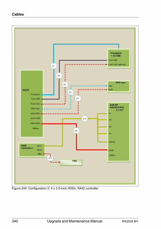
340 Upgrade and Maintenance Manual RX2530 M1
Cables
Figure 244: Configuration 2: 4 x 3.5-inch HDDs, RAID controller
SAS BPA3C40157818 4 x 3.5“
P1
P2
P3
P4
PWR
SMBus
SGPIO
D3279
SATA HDD
Frontpanel
Front USB
Front VGA
ODD Data
ODD PWR
HDD PWR
SMBus
DVD (opt.)
Frontpanel+ 2x USB
Front USB
Front VGA (optional)C1
Data
PWR
RAIDController 1
MLC1er 1
MLC2
iBBU
FBU
C13
C17
C9
C3
C6
C5
C8
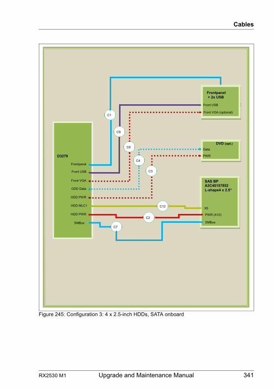
RX2530 M1 Upgrade and Maintenance Manual 341
Cables
Figure 245: Configuration 3: 4 x 2.5-inch HDDs, SATA onboard
D3279
HDD MLC1
Frontpanel
Front USB
Front VGA
ODD Data
ODD PWR
HDD PWR
SMBus
DVD (opt.)
SAS BPA3C40157852L-shape4 x 2.5“
Frontpanel+ 2x USB
Front USB
Front VGA (optional)C1
Data
PWR
X5
C2PWR (X10)
SMBusC7
C9
C3
C6
C4
C12
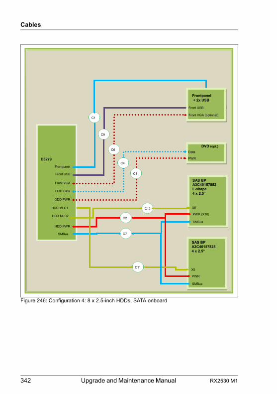
342 Upgrade and Maintenance Manual RX2530 M1
Cables
Figure 246: Configuration 4: 8 x 2.5-inch HDDs, SATA onboard
D3279
HDD MLC1
Frontpanel
Front USB
Front VGA
ODD Data
ODD PWR
HDD PWR
SMBus
DVD (opt.)
Frontpanel+ 2x USB
Front USB
Front VGA (optional)C1
Data
PWR
C12
C9
C3
C6
C4
C2
C7
SAS BPA3C40157852L-shape4 x 2.5“
X5
PWR (X10)
SMBus
SAS BPA3C401578284 x 2.5“
X5
PWR
SMBus
C11
HDD MLC2
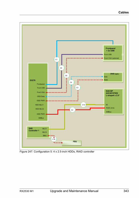
RX2530 M1 Upgrade and Maintenance Manual 343
Cables
Figure 247: Configuration 5: 4 x 2.5-inch HDDs, RAID controller
D3279
HDD MLC1
Frontpanel
Front USB
Front VGA
ODD Data
ODD PWR
HDD PWR
SMBus
DVD (opt.)
Frontpanel+ 2x USB
Front USB
Front VGA (optional)C1
Data
PWR
SASController 1
MLC1er 1
MLC2
iBBU
FBU
C15
C18
C9
C3
C6
C4
C2
SAS BPA3C40157852L-shape4 x 2.5“
X5
PWR (X10)
SMBus
HDD MLC2
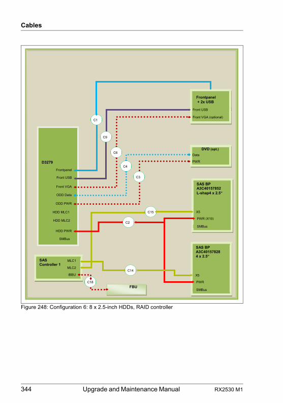
344 Upgrade and Maintenance Manual RX2530 M1
Cables
Figure 248: Configuration 6: 8 x 2.5-inch HDDs, RAID controller
D3279
HDD MLC1
Frontpanel
Front USB
Front VGA
ODD Data
ODD PWR
HDD PWR
SMBus
DVD (opt.)
Frontpanel+ 2x USB
Front USB
Front VGA (optional)C1
Data
PWR
SASController 1
MLC1er 1
MLC2
iBBU
FBU
C15
C18
C9
C3
C6
C4
C2
SAS BPA3C40157852L-shap4 x 2.5“
X5
PWR (X10)
SMBus
SAS BPA3C401578284 x 2.5“
X5
PWR
SMBus
C14
HDD MLC2
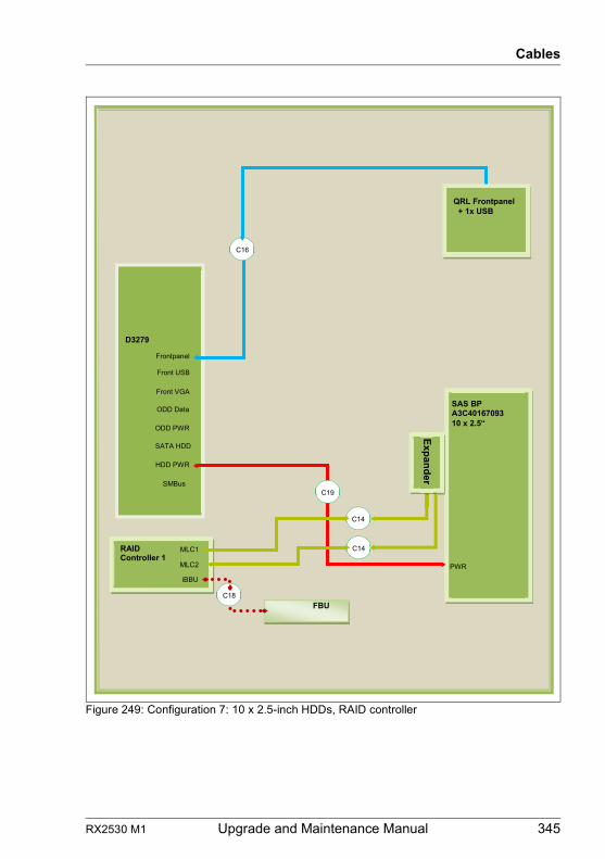
RX2530 M1 Upgrade and Maintenance Manual 345
Cables
Figure 249: Configuration 7: 10 x 2.5-inch HDDs, RAID controller
SAS BPA3C4016709310 x 2.5“
PWR
D3279
SATA HDD
Frontpanel
Front USB
Front VGA
ODD Data
ODD PWR
HDD PWR
SMBus
QRL Frontpanel+ 1x USB
C16
RAIDController 1
MLC1er 1
MLC2
iBBU
FBU
C14
C18
C19
C14
Expander
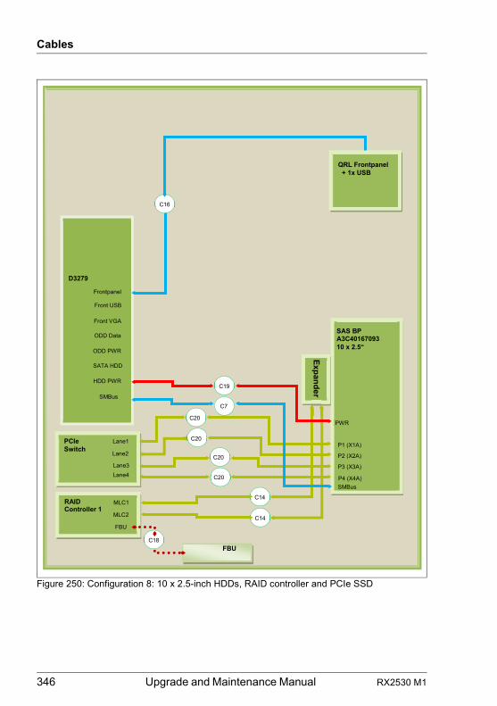
346 Upgrade and Maintenance Manual RX2530 M1
Cables
Figure 250: Configuration 8: 10 x 2.5-inch HDDs, RAID controller and PCIe SSD
SAS BPA3C4016709310 x 2.5“
PWR
D3279
SATA HDD
Frontpanel
Front USB
Front VGA
ODD Data
ODD PWR
HDD PWR
SMBus
QRL Frontpanel+ 1x USB
C16
RAIDController 1
MLC1er 1
MLC2
FBU
FBU
C14
C18
C19
C14
Expander
P1 (X1A)
P2 (X2A)
P3 (X3A)
P4 (X4A)
PCIeSwitch
Lane3
Lane1
Lane2
Lane4
C20
C20
C20
C20SMBus
C7
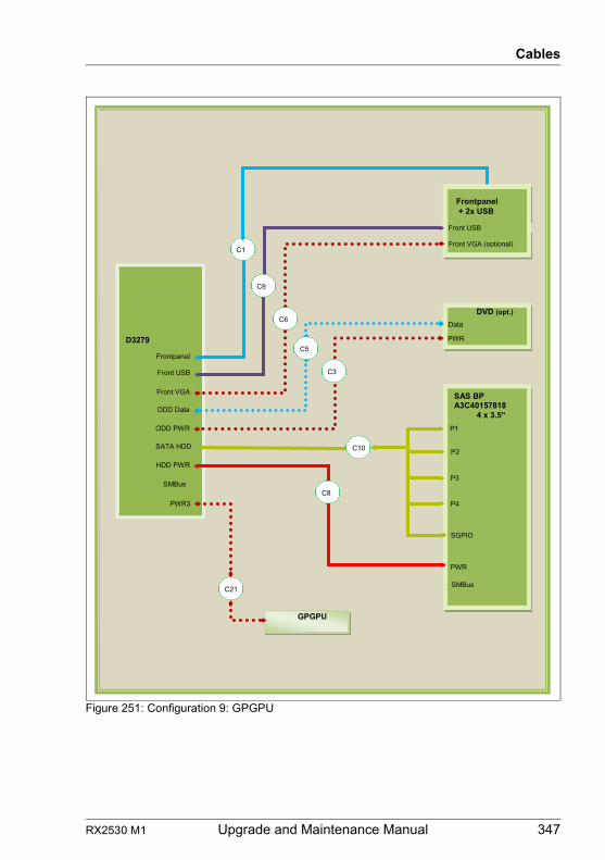
RX2530 M1 Upgrade and Maintenance Manual 347
Cables
Figure 251: Configuration 9: GPGPU
SAS BPA3C40157818 4 x 3.5“
P1
P2
P3
P4
PWR
SMBus
SGPIO
D3279
SATA HDD
Frontpanel
Front USB
Front VGA
ODD Data
ODD PWR
HDD PWR
SMBus
DVD (opt.)
Frontpanel+ 2x USB
Front USB
Front VGA (optional)C1
Data
PWR
PWR3
GPGPU
C10
C21
C9
C3
C6
C5
C8
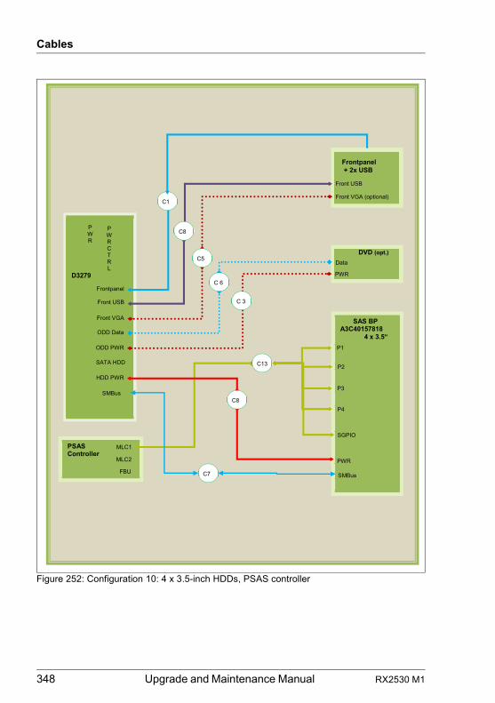
348 Upgrade and Maintenance Manual RX2530 M1
Cables
Figure 252: Configuration 10: 4 x 3.5-inch HDDs, PSAS controller
SAS BP A3C40157818 4 x 3.5“
P1
P2
P3
P4
PWR
SMBus
SGPIO
D3279
SATA HDD
PWR CTRL
PWR
Frontpanel
Front USB
Front VGA
ODD Data
ODD PWR
HDD PWR
SMBus
DVD (opt.)
Frontpanel + 2x USB
Front USB
Front VGA (optional) C1
Data
PWR
PSAS Controller
MLC1 er
MLC2 FBU
C13
C8
C 3
C5
C 6
C8
C7
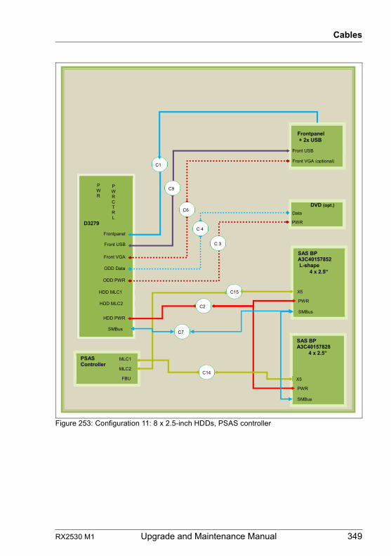
RX2530 M1 Upgrade and Maintenance Manual 349
Cables
Figure 253: Configuration 11: 8 x 2.5-inch HDDs, PSAS controller
D3279
HDD MLC1
PWR CTRL
PWR
Frontpanel
Front USB
Front VGA
ODD Data
ODD PWR
HDD PWR
SMBus
DVD (opt.)
Frontpanel + 2x USB
Front USB
Front VGA (optional) C1
Data
PWR
PSAS Controller
MLC1 er
MLC2 FBU
C15
C7
C9
C 3
C6
C 4
C2
SAS BP A3C40157852 L-shape 4 x 2.5“
X5
PWR
SMBus
SAS BP A3C40157828 4 x 2.5“
X5
PWR
SMBus
C14
HDD MLC2
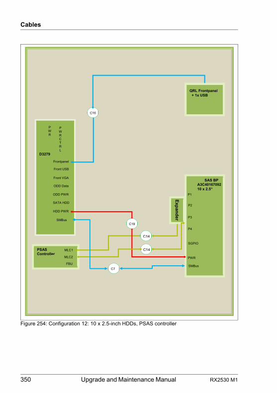
350 Upgrade and Maintenance Manual RX2530 M1
Cables
Figure 254: Configuration 12: 10 x 2.5-inch HDDs, PSAS controller
SAS BP
A3C40167092
10 x 2.5“
P1
P2
P3
P4
PWR
SMBus
SGPIO
D3279
SATA HDD
PWR CTRL
PWR
Frontpanel
Front USB
Front VGA
ODD Data
ODD PWR
HDD PWR
SMBus
QRL Frontpanel + 1x USB
C16
PSAS Controller
MLC1 er
MLC2 FBU
C14
C7
C19
C14
Expander
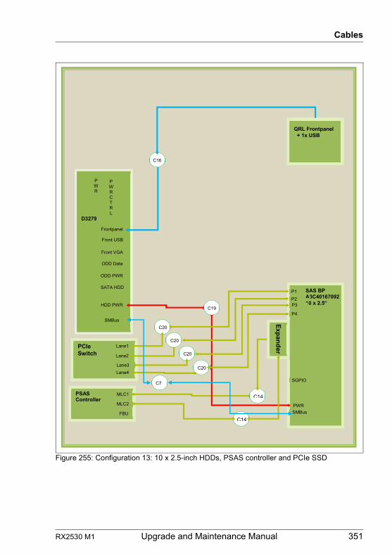
RX2530 M1 Upgrade and Maintenance Manual 351
Cables
Figure 255: Configuration 13: 10 x 2.5-inch HDDs, PSAS controller and PCIe SSD
SAS BP
A3C40167092
10 x 2.5“
SP1 A310
P2 1P3
P4
PWR SMBus
SGPIO
D3279
SATA HDD
PWR CTRL
PWR
Frontpanel
Front USB
Front VGA
ODD Data
ODD PWR
HDD PWR
SMBus
QRL Frontpanel + 1x USB
C16
PSAS Controller
MLC1 er
MLC2 FBU
C14
C19
C14
PCIe Switch
Lane3
Lane1 Lane2
Lane4
C20
C20
C20
C20
C7
Expander
352 Upgrade and Maintenance Manual RX2530 M1
Cables
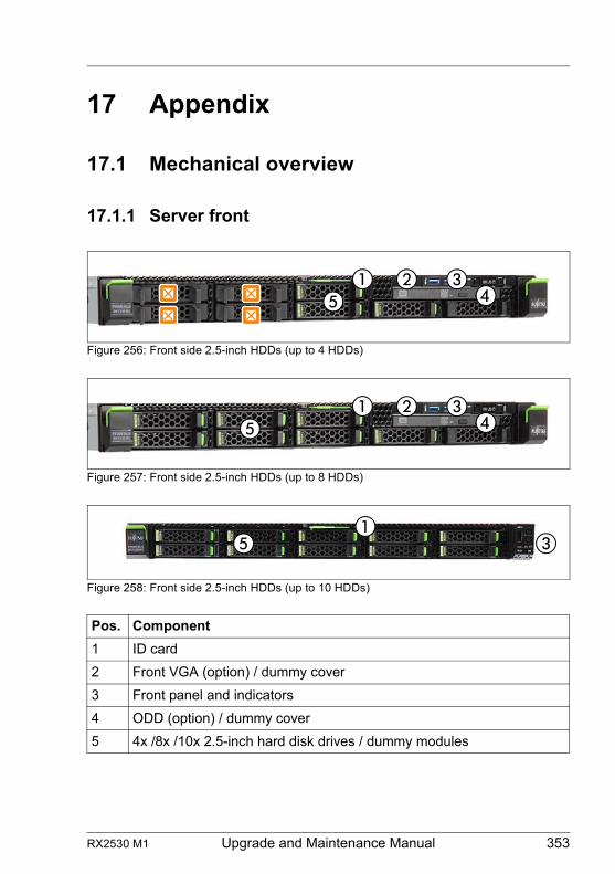
RX2530 M1 Upgrade and Maintenance Manual 353
17 Appendix
17.1 Mechanical overview
17.1.1 Server front
Figure 256: Front side 2.5-inch HDDs (up to 4 HDDs)
Figure 257: Front side 2.5-inch HDDs (up to 8 HDDs)
Figure 258: Front side 2.5-inch HDDs (up to 10 HDDs)
Pos. Component
1 ID card
2 Front VGA (option) / dummy cover
3 Front panel and indicators
4 ODD (option) / dummy cover
5 4x /8x /10x 2.5-inch hard disk drives / dummy modules
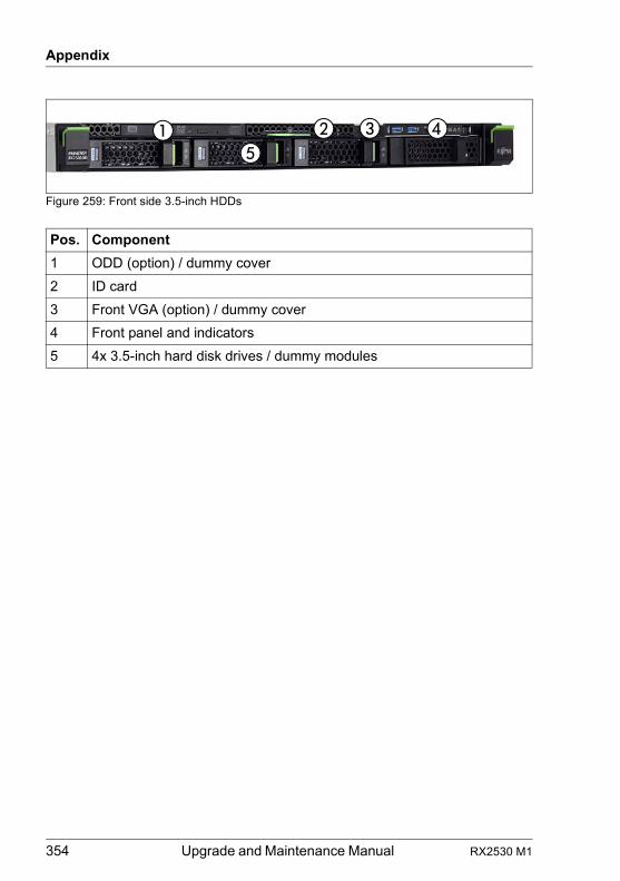
354 Upgrade and Maintenance Manual RX2530 M1
Appendix
Figure 259: Front side 3.5-inch HDDs
Pos. Component
1 ODD (option) / dummy cover
2 ID card
3 Front VGA (option) / dummy cover
4 Front panel and indicators
5 4x 3.5-inch hard disk drives / dummy modules
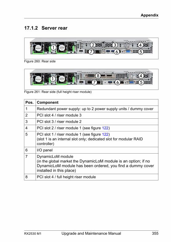
RX2530 M1 Upgrade and Maintenance Manual 355
Appendix
17.1.2 Server rear
Figure 260: Rear side
Figure 261: Rear side (full height riser module)
Pos. Component
1 Redundant power supply: up to 2 power supply units / dummy cover
2 PCI slot 4 / riser module 3
3 PCI slot 3 / riser module 2
4 PCI slot 2 / riser module 1 (see figure 122)
5 PCI slot 1 / riser module 1 (see figure 122)(slot 1 is an internal slot only; dedicated slot for modular RAID controller)
6 I/O panel
7 DynamicLoM module(in the global market the DynamicLoM module is an option; if no DynamicLoM module has been ordered, you find a dummy cover installed in this place)
8 PCI slot 4 / full height riser module
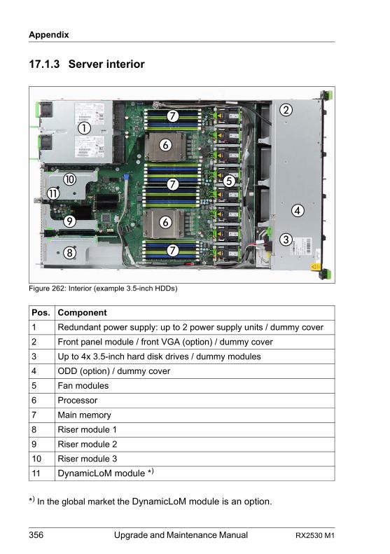
356 Upgrade and Maintenance Manual RX2530 M1
Appendix
17.1.3 Server interior
Figure 262: Interior (example 3.5-inch HDDs)
*) In the global market the DynamicLoM module is an option.
Pos. Component
1 Redundant power supply: up to 2 power supply units / dummy cover
2 Front panel module / front VGA (option) / dummy cover
3 Up to 4x 3.5-inch hard disk drives / dummy modules
4 ODD (option) / dummy cover
5 Fan modules
6 Processor
7 Main memory
8 Riser module 1
9 Riser module 2
10 Riser module 3
11 DynamicLoM module *)
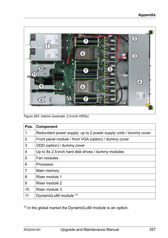
RX2530 M1 Upgrade and Maintenance Manual 357
Appendix
Figure 263: Interior (example: 2.5-inch HDDs)
*) In the global market the DynamicLoM module is an option.
Pos. Component
1 Redundant power supply: up to 2 power supply units / dummy cover
2 Front panel module / front VGA (option) / dummy cover
3 ODD (option) / dummy cover
4 Up to 8x 2.5-inch hard disk drives / dummy modules
5 Fan modules
6 Processor
7 Main memory
8 Riser module 1
9 Riser module 2
10 Riser module 3
11 DynamicLoM module *)
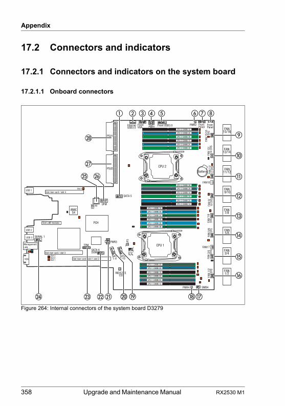
358 Upgrade and Maintenance Manual RX2530 M1
Appendix
17.2 Connectors and indicators
17.2.1 Connectors and indicators on the system board
17.2.1.1 Onboard connectors
Figure 264: Internal connectors of the system board D3279
iRMCS4
INDICATECSS
TPM
Battery
VGA
USB 2
USB 3
ManagementLAN
Slot riser card / slot 1 and 2
PCH
CPU 1 DIMM 3D
JP3
FAN
11/
12 S
YS
SATA 1-4
Front Panel
Front VGA
FAN
9/10
SYS
FAN
7/8
SYS
FAN
5/6
SYS
FAN
3/4
SYS
FAN
1/2
SYS
USB 1
Slot riser card / slot 3
Slot riser card / slot 4
Slot 3
FAN 11/12
FAN 9/10
FAN 7/8
FAN 5/6
FAN 3/4
FAN 1/2
UFM
SERIAL 1
FAN 13/14
FAN 15/16
CPU 1
CPU 2
Slot 2Slot 1
Slot 4
CPU 1 DIMM 2D
CPU 1 DIMM 1D
CPU 1 DIMM 3C
CPU 1 DIMM 2C
CPU 1 DIMM 1C
CPU 2 DIMM 3H
CPU 2 DIMM 2H
CPU 2 DIMM 1H
CPU 2 DIMM 3G
CPU 2 DIMM 2G
CPU 2 DIMM 1G
CPU 1 DIMM 1A
CPU 1 DIMM 2A
CPU 1 DIMM 3A
CPU 1 DIMM 1B
CPU 1 DIMM 2B
CPU 1 DIMM 3B
CPU 2 DIMM 1E
CPU 2 DIMM 2E
CPU 2 DIMM 3E
CPU 2 DIMM 1F
CPU 2 DIMM 2F
CPU 2 DIMM 3F
FAN
13/
14
SYS
FAN
15/1
6
SYS
PWR4 SMB4
FAN17
FAN18
Front Panel
PWR2PWR1 Front USB3.0
PWR3
MicroSD
SATA7-10
SATA 6 DOM
SATA 5
InternalUSB3.0
PSU1
PSU2
JP2
JP1
11
2
Slot LoM modules
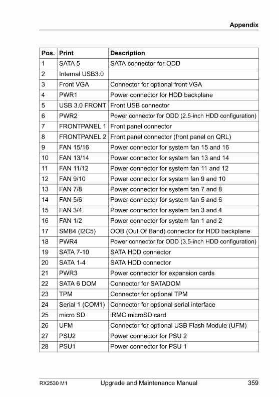
RX2530 M1 Upgrade and Maintenance Manual 359
Appendix
Pos. Print Description
1 SATA 5 SATA connector for ODD
2 Internal USB3.0
3 Front VGA Connector for optional front VGA
4 PWR1 Power connector for HDD backplane
5 USB 3.0 FRONT Front USB connector
6 PWR2 Power connector for ODD (2.5-inch HDD configuration)
7 FRONTPANEL 1 Front panel connector
8 FRONTPANEL 2 Front panel connector (front panel on QRL)
9 FAN 15/16 Power connector for system fan 15 and 16
10 FAN 13/14 Power connector for system fan 13 and 14
11 FAN 11/12 Power connector for system fan 11 and 12
12 FAN 9/10 Power connector for system fan 9 and 10
13 FAN 7/8 Power connector for system fan 7 and 8
14 FAN 5/6 Power connector for system fan 5 and 6
15 FAN 3/4 Power connector for system fan 3 and 4
16 FAN 1/2 Power connector for system fan 1 and 2
17 SMB4 (I2C5) OOB (Out Of Band) connector for HDD backplane
18 PWR4 Power connector for ODD (3.5-inch HDD configuration)
19 SATA 7-10 SATA HDD connector
20 SATA 1-4 SATA HDD connector
21 PWR3 Power connector for expansion cards
22 SATA 6 DOM Connector for SATADOM
23 TPM Connector for optional TPM
24 Serial 1 (COM1) Connector for optional serial interface
25 micro SD iRMC microSD card
26 UFM Connector for optional USB Flash Module (UFM)
27 PSU2 Power connector for PSU 2
28 PSU1 Power connector for PSU 1
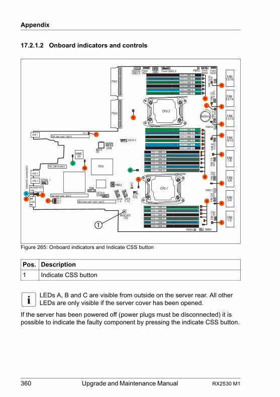
360 Upgrade and Maintenance Manual RX2530 M1
Appendix
17.2.1.2 Onboard indicators and controls
Figure 265: Onboard indicators and Indicate CSS button
I LEDs A, B and C are visible from outside on the server rear. All other LEDs are only visible if the server cover has been opened.
If the server has been powered off (power plugs must be disconnected) it is possible to indicate the faulty component by pressing the indicate CSS button.
Pos. Description
1 Indicate CSS button
�
iRMCS4
exte
rnal
con
nect
ors
INDICATECSS
TPM
I
Battery
VGA
USB 2
USB 3
ManagementLAN
Slot riser card / slot 1 and 2
PCH
CPU 1 DIMM 3D
L
JP3
FAN
11/
12 S
YS
SATA 1-4
Front Panel
Front VGA
G
FAN
9/10
SYS
FAN
7/8
SYS
FAN
5/6
SYS
FAN
3/4
SYS
FAN
1/2
SYS
USB 1
Slot riser card / slot 3
Slot riser card / slot 4
Slot 3
K
K
FAN 11/12
FAN 9/10
FAN 7/8
FAN 5/6
FAN 3/4
FAN 1/2
UFM
SERIAL 1
BCA
H
FAN 13/14
FAN 15/16
G
K
K
K
CPU 1
CPU 2
Slot 2Slot 1
F
Slot 4 F
H
CPU 1 DIMM 2D
CPU 1 DIMM 1D
CPU 1 DIMM 3C
CPU 1 DIMM 2C
CPU 1 DIMM 1C
CPU 2 DIMM 3H
CPU 2 DIMM 2H
CPU 2 DIMM 1H
CPU 2 DIMM 3G
CPU 2 DIMM 2G
CPU 2 DIMM 1G
CPU 1 DIMM 1A
CPU 1 DIMM 2A
CPU 1 DIMM 3A
CPU 1 DIMM 1B
CPU 1 DIMM 2B
CPU 1 DIMM 3B
CPU 2 DIMM 1E
CPU 2 DIMM 2E
CPU 2 DIMM 3E
CPU 2 DIMM 1F
CPU 2 DIMM 2F
CPU 2 DIMM 3F
K
K
FAN
13/
14
SYS
FAN
15/1
6
SYS
PWR4 SMB4
FAN17
FAN18
K
H
Front Panel
PWR2PWR1 Front USB3.0
PWR3
MicroSD
SATA7-10
SATA 6 DOM
SATA 5
InternalUSB3.0
PSU1
PSU2
JP2
JP1
11
2
Slot LoM modules MN
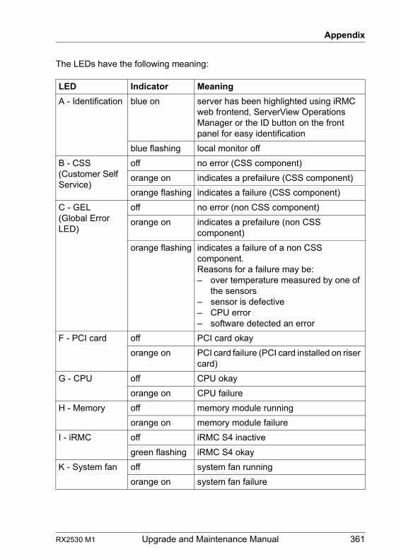
RX2530 M1 Upgrade and Maintenance Manual 361
Appendix
The LEDs have the following meaning:
LED Indicator Meaning
A - Identification blue on server has been highlighted using iRMC web frontend, ServerView Operations Manager or the ID button on the front panel for easy identification
blue flashing local monitor off
B - CSS(Customer Self Service)
off no error (CSS component)
orange on indicates a prefailure (CSS component)
orange flashing indicates a failure (CSS component)
C - GEL(Global Error LED)
off no error (non CSS component)
orange on indicates a prefailure (non CSS component)
orange flashing indicates a failure of a non CSS component.Reasons for a failure may be:– over temperature measured by one of
the sensors– sensor is defective– CPU error– software detected an error
F - PCI card off PCI card okay
orange on PCI card failure (PCI card installed on riser card)
G - CPU off CPU okay
orange on CPU failure
H - Memory off memory module running
orange on memory module failure
I - iRMC off iRMC S4 inactive
green flashing iRMC S4 okay
K - System fan off system fan running
orange on system fan failure
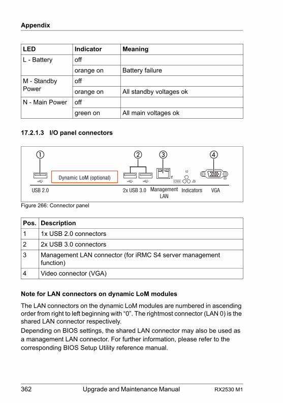
362 Upgrade and Maintenance Manual RX2530 M1
Appendix
17.2.1.3 I/O panel connectors
Figure 266: Connector panel
Note for LAN connectors on dynamic LoM modules
The LAN connectors on the dynamic LoM modules are numbered in ascending order from right to left beginning with “0”. The rightmost connector (LAN 0) is the shared LAN connector respectively.
Depending on BIOS settings, the shared LAN connector may also be used as a management LAN connector. For further information, please refer to the corresponding BIOS Setup Utility reference manual.
L - Battery off
orange on Battery failure
M - Standby Power
off
orange on All standby voltages ok
N - Main Power off
green on All main voltages ok
Pos. Description
1 1x USB 2.0 connectors
2 2x USB 3.0 connectors
3 Management LAN connector (for iRMC S4 server management function)
4 Video connector (VGA)
LED Indicator Meaning
Management LAN
Indicators VGA2x USB 3.0USB 2.0
Dynamic LoM (optional)
�� � �
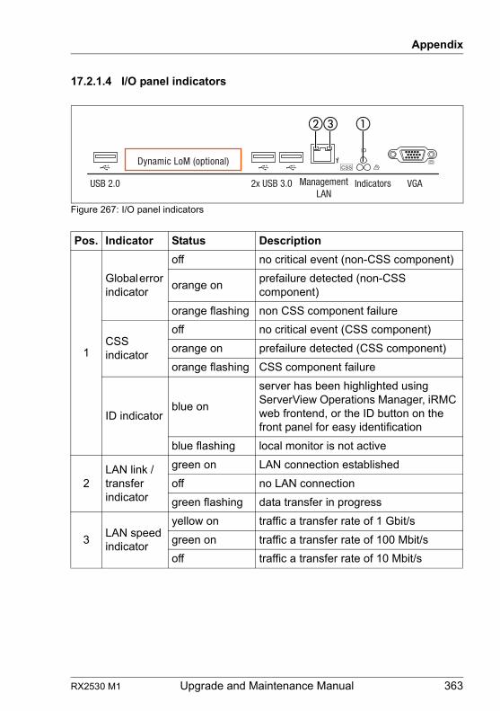
RX2530 M1 Upgrade and Maintenance Manual 363
Appendix
17.2.1.4 I/O panel indicators
Figure 267: I/O panel indicators
Pos. Indicator Status Description
1
Global error indicator
off no critical event (non-CSS component)
orange onprefailure detected (non-CSS component)
orange flashing non CSS component failure
CSS indicator
off no critical event (CSS component)
orange on prefailure detected (CSS component)
orange flashing CSS component failure
ID indicatorblue on
server has been highlighted using ServerView Operations Manager, iRMC web frontend, or the ID button on the front panel for easy identification
blue flashing local monitor is not active
2LAN link / transfer indicator
green on LAN connection established
off no LAN connection
green flashing data transfer in progress
3LAN speed indicator
yellow on traffic a transfer rate of 1 Gbit/s
green on traffic a transfer rate of 100 Mbit/s
off traffic a transfer rate of 10 Mbit/s
�
Management LAN
Indicators VGA2x USB 3.0USB 2.0
Dynamic LoM (optional)
��
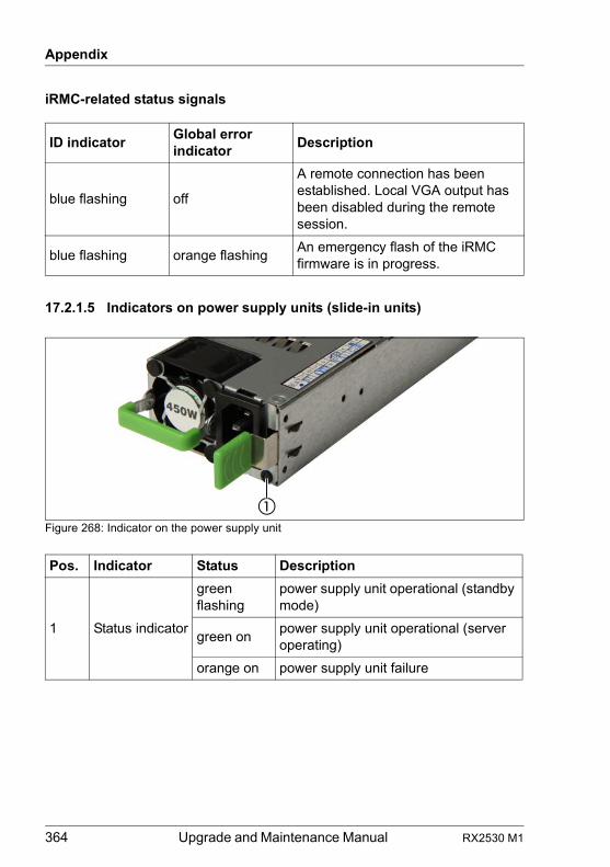
364 Upgrade and Maintenance Manual RX2530 M1
Appendix
iRMC-related status signals
17.2.1.5 Indicators on power supply units (slide-in units)
Figure 268: Indicator on the power supply unit
ID indicatorGlobal error indicator
Description
blue flashing off
A remote connection has been established. Local VGA output has been disabled during the remote session.
blue flashing orange flashingAn emergency flash of the iRMC firmware is in progress.
Pos. Indicator Status Description
1 Status indicator
green flashing
power supply unit operational (standby mode)
green onpower supply unit operational (server operating)
orange on power supply unit failure
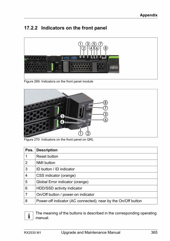
RX2530 M1 Upgrade and Maintenance Manual 365
Appendix
17.2.2 Indicators on the front panel
Figure 269: Indicators on the front panel module
Figure 270: Indicators on the front panel on QRL
I The meaning of the buttons is described in the corresponding operating manual.
Pos. Description
1 Reset button
2 NMI button
3 ID button / ID indicator
4 CSS indicator (orange)
5 Global Error indicator (orange)
6 HDD/SSD activity indicator
7 On/Off button / power-on indicator
8 Power-off indicator (AC connected); near by the On/Off button
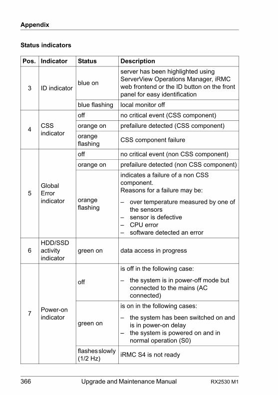
366 Upgrade and Maintenance Manual RX2530 M1
Appendix
Status indicators
Pos. Indicator Status Description
3 ID indicatorblue on
server has been highlighted using ServerView Operations Manager, iRMC web frontend or the ID button on the front panel for easy identification
blue flashing local monitor off
4CSS indicator
off no critical event (CSS component)
orange on prefailure detected (CSS component)
orange flashing
CSS component failure
5Global Error indicator
off no critical event (non CSS component)
orange on prefailure detected (non CSS component)
orange flashing
indicates a failure of a non CSS component.Reasons for a failure may be:
– over temperature measured by one of the sensors
– sensor is defective– CPU error– software detected an error
6HDD/SSD activity indicator
green on data access in progress
7Power-on indicator
off
is off in the following case:
– the system is in power-off mode but connected to the mains (AC connected)
green on
is on in the following cases:
– the system has been switched on and is in power-on delay
– the system is powered on and in normal operation (S0)
flashes slowly (1/2 Hz)
iRMC S4 is not ready
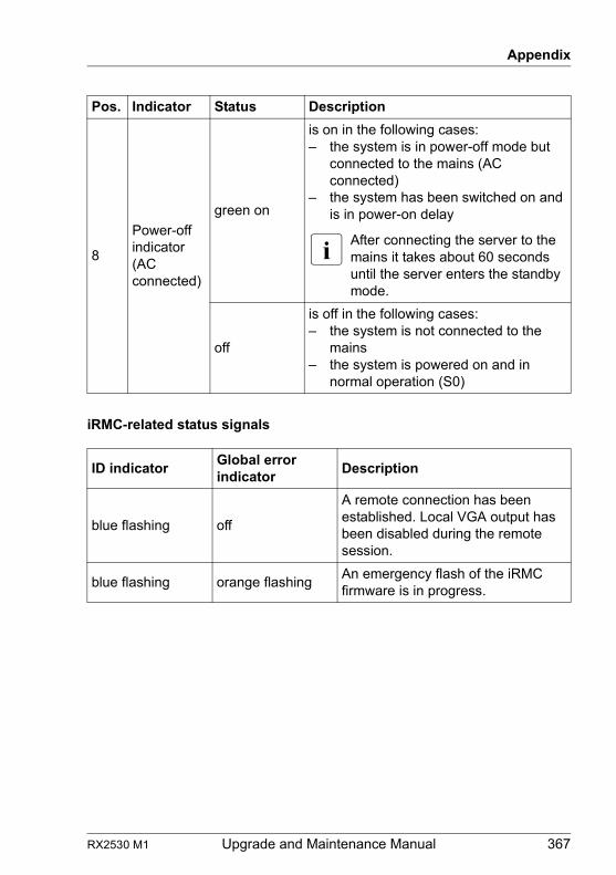
RX2530 M1 Upgrade and Maintenance Manual 367
Appendix
iRMC-related status signals
8
Power-off indicator (AC connected)
green on
is on in the following cases:– the system is in power-off mode but
connected to the mains (AC connected)
– the system has been switched on and is in power-on delay
I After connecting the server to the mains it takes about 60 seconds until the server enters the standby mode.
off
is off in the following cases:– the system is not connected to the
mains– the system is powered on and in
normal operation (S0)
ID indicatorGlobal error indicator
Description
blue flashing off
A remote connection has been established. Local VGA output has been disabled during the remote session.
blue flashing orange flashingAn emergency flash of the iRMC firmware is in progress.
Pos. Indicator Status Description
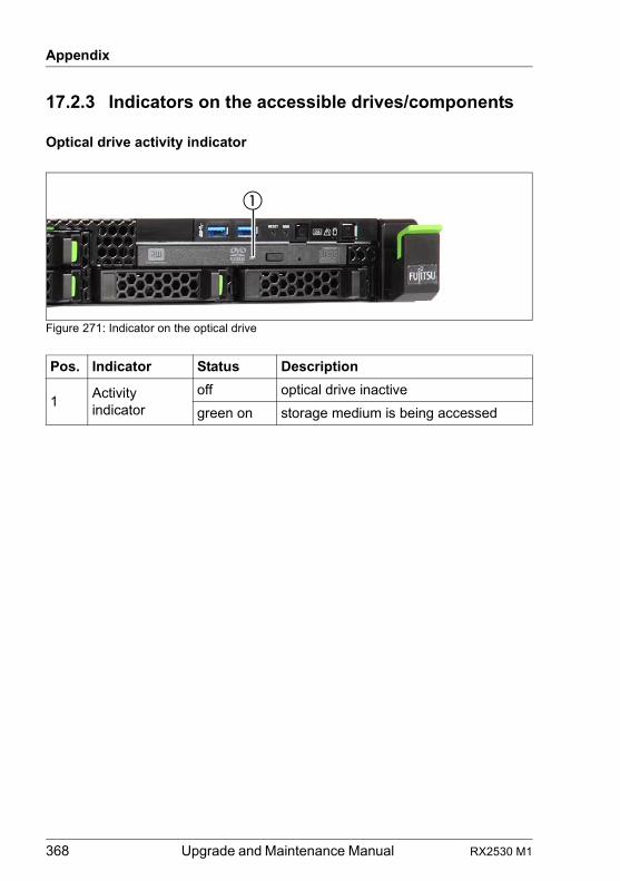
368 Upgrade and Maintenance Manual RX2530 M1
Appendix
17.2.3 Indicators on the accessible drives/components
Optical drive activity indicator
Figure 271: Indicator on the optical drive
Pos. Indicator Status Description
1Activity indicator
off optical drive inactive
green on storage medium is being accessed
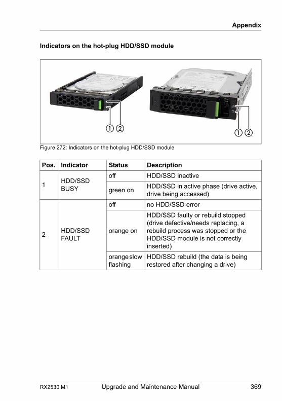
RX2530 M1 Upgrade and Maintenance Manual 369
Appendix
Indicators on the hot-plug HDD/SSD module
Figure 272: Indicators on the hot-plug HDD/SSD module
Pos. Indicator Status Description
1HDD/SSD BUSY
off HDD/SSD inactive
green onHDD/SSD in active phase (drive active, drive being accessed)
2HDD/SSD FAULT
off no HDD/SSD error
orange on
HDD/SSD faulty or rebuild stopped (drive defective/needs replacing, a rebuild process was stopped or the HDD/SSD module is not correctly inserted)
orange slow flashing
HDD/SSD rebuild (the data is being restored after changing a drive)
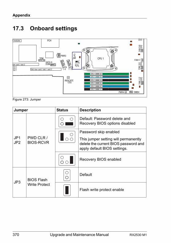
370 Upgrade and Maintenance Manual RX2530 M1
Appendix
17.3 Onboard settings
Figure 273: Jumper
Jumper Status Description
JP1JP2
PWD CLR / BIOS-RCVR
Default: Password delete and Recovery BIOS options disabled
Password skip enabled
This jumper setting will permanently delete the current BIOS password and apply default BIOS settings.
Recovery BIOS enabled
JP3BIOS Flash Write Protect
Default
Flash write protect enable
INDICATECSS
TPM
Slot riser card / slot 1 and 2
PCH
CPU 1 DIMM 3DJP
3
SATA 1-4
FA SYFA
N 5/
6
SY
SFA
N 3/
4
S
YSFA
N 1/
2
SY
S
iser card / slot 3Slot 3
CPU 1
Slot 2Slot 1
CPU 1 DIMM 2D
CPU 1 DIMM 1D
CPU 1 DIMM 3C
CPU 1 DIMM 2C
CPU 1 DIMM 1C
PWR4 SMB4
FAN17
PWR3
SATA7-10
SATA 6 DOM
JP2
JP1
11
2
M modules
RX2530 M1 Upgrade and Maintenance Manual 371
Appendix
17.4 Minimum startup configuration
If the server does not start up or other problems occur, it may be necessary to take the system down to its most basic configuration in order to isolate the defective component.
The minimum startup configuration consists of the following components and cables:
Ê "Shutting down the server" on page 48
Ê "Disconnecting the server from the mains" on page 49
Ê Take the system down to its minimum startup configuration.
Ê "Connecting the server to the mains" on page 60
Ê Connect a keyboard, mouse and display to the server.
Ê Switch on the server as described in section "Switching on the server" on page 61.
Field Replaceable Units (FRU)
Component Notes
System board no TPM, UFM or expansion cards installed
CPU with CPU heat sink
1 memory module installed in DIMM slot 1A
Front panel module
Power supply unit
Table 4: Minimum startup configuration - components
Cable Notes
Front panel cable
Power cable
Table 5: Minimum startup configuration - cables
372 Upgrade and Maintenance Manual RX2530 M1
Appendix
V CAUTION!
Since the fan module is not included in the minimum startup configuration, the server must be shut down immediately after the diagnostic process is complete (POST phase has been passed).
The minimum startup configuration must be used exclusively for diagnostic purposes by maintenance personnel, never in daily operation!


![PRIMERGY RX2530 M4 RX2540 M4 / RX2520 M4 / …...2 / 11 Copyright 2017-2019 FUJITSU LIMITED 6. Management LANについて BIOS 設定の[Server Management]メニュー -[iRMC LAN](https://img.dokumen.tips/doc/110x75/5e4edf1b35835d07515b9799/primergy-rx2530-m4-rx2540-m4-rx2520-m4-2-11-copyright-2017-2019-fujitsu.jpg)