Embed Size (px)
Citation preview
FT1A Touch External Device Setup Manual Supplement
Modbus RTU Slave Function
B-1672(0)

1
Introduction This manual is supplement for “Automation Organizer External Device Setup Manual B912(25)”, and explains Modbus RTU Slave function which is added in Automation Organizer Ver.2.21(WindO/I-NV2 Ver.5.11).
2
Contants Table 1. Overview .............................................................................................................................................. 3
1.1. Overview ....................................................................................................................................... 3 1.2. Operation of the Communication ................................................................................................ 3 1.3. Read/Write from the External Device ......................................................................................... 3
2. Devices .................................................................................................................................................. 4 3. Settings................................................................................................................................................. 4 4. Communication Format ...................................................................................................................... 5
4.1. Basic Format ................................................................................................................................ 5 4.2. Supported Function ...................................................................................................................... 6 4.3. Function Details ........................................................................................................................... 6
4.3.1. FC3 Read multiple registers ................................................................................................ 6 4.3.2. FC16 Write multiple registers ............................................................................................. 7 4.3.3. FC1 Read coils ....................................................................................................................... 7 4.3.4. FC2 Read discrete inputs ..................................................................................................... 9 4.3.5. FC4 Read input registers ................................................................................................... 10 4.3.6. FC5 Write coil ..................................................................................................................... 10 4.3.7. FC6 Write single register ................................................................................................... 11

3
FT1A Touch Modbus RTU Slave function 1. Overview 1.1. Overview
Modbus RTU Slave function is a method that reads and writes FT1A Touch communication devices via RS232C or RS485/422 from a PC or PLC (referred to as the external device). The read/write of a device is performed using the Modbus RTU protocol.
1.2. Operation of the Communication The external device is capable of reading/writing to the FT1A Touch communication devices. It is also possible to read or write communication devices from the FT1A Touch.
1.3. Read/Write from the External Device The external device is capable of reading or writing the data in the communication devices at the any timing.

4
2. Devices The following devices are available for Modbus RTU Slave function. Bit Device
Device
Name
Device
Symbol
Address Range FT1A Touch
Read/Write
External
Device
Read/Write
Address
Gradual
Coil Status C 1 - 4096 R/W R/W Decimal
Input Status I 100001 - 104096 R/W R Decimal
Word Device
Device
Name
Device
Symbol
Address Range FT1A Touch
Read/Write
External
Device
Read/Write
Address
Gradual
Holding
Register
HR 400001 - 404096 R/W R/W Decimal
Input
Register
IR 300001 - 304096 R/W R Decimal
3. Settings
The settings of the Modbus RTU Slave function can be configured in the Configuration - System Setup - Project dialog boxes in WindO/I-NV3. The following table lists the configurable settings. Configure the settings according to the external device to be used.
Dialog Box - Tab Settings Description
Project Settings -
Host I/F Driver or
Communication
Driver
Manufacturer Select “Modicon”.
Host I/F Driver
Communication
Driver
Select “Modbus RTU Slave”.
Slave Address Set FT1A Touch slave address.
Project Settings -
Communication
Interface
Protocol When using the O/I Link, select “Enable”.

5
4. Communication Format This chapter describes the communication format of the Modbus RTU communication. The Modbus RTU communication supports functions of the MODBUS APPLICATION PROTOCOL SPECIFICATION V1.1b3. For details about the communication methods, refer to the MODBUS over Serial LineSpecification and Implementation Guide V1.02 as well as this manual.
4.1. Basic Format The following table lists the basic format of communications. The same format applies to both requests and responses. Data is processed as a byte sequences. Description
Idle 3.5 characters (*1)
Byte 0 Slave Address Set FT1A Touch slave address
Byte 1 Function code (*2)
Byte 2- Data (*3)
Byte n-1 CRC(*4)
Byte n
Idle 3.5 characters
(*1) Idle means no data flowing on the communication line.
RTU mode requires a minimum of 3.5-character-long idle time between frames to determine the beginning of a frame.
(*2) Numbers assigned for functions such as reading and writing. (*3) Data required for each processing. (*4) CRC is calculated by the following method. CRC
RTU mode uses CRC check codes. Modbus RTU Mode — Calculating the CRC-16 (cyclic redundancy checksum)
Calculate the BCC using CRC-16 for the range from the slave number to the byte immediately before the BCC. The generation polynomial is: X16 + X15 + X2 + 1.
1. Take the exclusive OR (XOR) of FFFFh and the first 1-byte data at the slave number. 2. Shift the result by 1 bit to the right. When a carry occurs, take the exclusive OR (XOR) of A001h, then go to step 3. If not, directly go to step 3. 3. Repeat step 2, shifting 8 times. 4. Take the exclusive OR (XOR) of the result and the next 1-byte data.
6
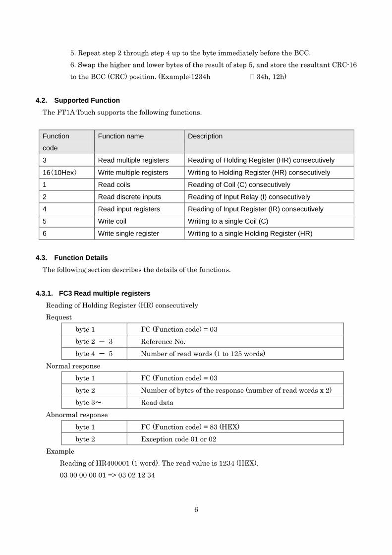
5. Repeat step 2 through step 4 up to the byte immediately before the BCC. 6. Swap the higher and lower bytes of the result of step 5, and store the resultant CRC-16 to the BCC (CRC) position. (Example:1234h 34h, 12h)
4.2. Supported Function
The FT1A Touch supports the following functions.
Function
code
Function name Description
3 Read multiple registers Reading of Holding Register (HR) consecutively
16(10Hex) Write multiple registers Writing to Holding Register (HR) consecutively
1 Read coils Reading of Coil (C) consecutively
2 Read discrete inputs Reading of Input Relay (I) consecutively
4 Read input registers Reading of Input Register (IR) consecutively
5 Write coil Writing to a single Coil (C)
6 Write single register Writing to a single Holding Register (HR)
4.3. Function Details
The following section describes the details of the functions.
4.3.1. FC3 Read multiple registers Reading of Holding Register (HR) consecutively Request
byte 1 FC (Function code) = 03 byte 2 - 3 Reference No. byte 4 - 5 Number of read words (1 to 125 words)
Normal response byte 1 FC (Function code) = 03 byte 2 Number of bytes of the response (number of read words x 2) byte 3~ Read data
Abnormal response byte 1 FC (Function code) = 83 (HEX) byte 2 Exception code 01 or 02
Example Reading of HR400001 (1 word). The read value is 1234 (HEX). 03 00 00 00 01 => 03 02 12 34

7
4.3.2. FC16 Write multiple registers Writing to Holding Register (HR) consecutively Request
byte 1 FC (Function code) = 10 (HEX) byte 2 - 3 Reference No. byte 4 - 5 Number of write words (1 to 100 words) byte 6 Number of write bytes (2 x number of write words) byte 7 ~ Write data
Normal response byte 1 FC (Function code) = 10(HEX) byte 2 - 3 Reference No. byte 4~ Number of write words
Abnormal response byte 1 FC (Function code) = 90 (HEX) byte 2 Exception code 01 or 02
Example Writing to HR400001 (1 word). The write value is 1234 (HEX). 10 00 00 00 01 02 12 34 => 10 00 00 00 01
4.3.3. FC1 Read coils Reading of Coil (C) consecutively Request
byte 1 FC (Function code) = 01 byte 2 - 3 Reference No. byte 4 - 5 Number of read bits (1 to 2000 bits)
Normal response byte 1 FC (Function code) = 01 byte 2 Number of bytes for the response ((number of read bits +7)/8) byte 3 ~ Read data
Abnormal response byte 1 FC (Function code) = 81 (HEX) byte 2 Exception code 01 or 02
Example Reading of C1. 1 bit. The read value is 1. 01 00 00 00 01 => 01 01 01

8
Data sequence of read value When two or more data are read out, the read data are arranged starting from the lowest address by 8 bits (1 byte). Within any 1 byte, data in the lower address is set to the lower bit. The data in the unread bit becomes “0”. For example, when reading an 11-bit data as shown below, the read value becomes 21 03.
Address Data Remarks
C 1 1 Data for the 1st byte
Bit pattern= 00100001 = 21 (HEX) C 2 0
C 3 0
C 4 0
C 5 0
C 6 1
C 7 0
C 8 0
C 9 1 Data for 2nd byte
Bit pattern 00000011 = 03 (HEX) C 10 1
C 11 0
C 12 0
C 13 0
C 14 0
C 15 0
C 16 0

9
4.3.4. FC2 Read discrete inputs Reading of Input Relay (I) consecutively Request
byte 1 FC (Function code)=02 byte 2 - 3 Reference No. byte 4 - 5 Number of read bits (1 to 2000 bits)
Normal response byte 1 FC (Function code)=02 byte 2 Number of bytes for the response ((number of read bits+7)/8) byte 3~ Read data
Abnormal response byte 1 FC (Function code)=82 (HEX) byte 2 Exception code 01 or 02
Example Reading of I100001. 1 bit. The read value is 1. 02 00 00 00 01 => 02 01 01 The data sequence for the read value is similar to that of FC1 Read Coils.

10
4.3.5. FC4 Read input registers Reading of Input Register (IR) consecutively Request
byte 1 FC (Function code)=04 byte 2 - 3 Reference No. byte 4 - 5 Number of read words (1 to 125 words)
Normal response byte 1 FC (Function code)=04 byte 2 Number of bytes for the response (number of read words x 2) byte 3 ~ Read data
Abnormal response byte 1 FC (Function code)=84 (HEX) byte 2 Exception code 01 or 02
Example Reading of IR300001 (1 word). The read value is 1234 (HEX). 04 00 00 00 01 => 04 02 12 34
4.3.6. FC5 Write coil Writing to a single Coil (C) Request
byte 1 FC (Function code)=05 byte 2 - 3 Reference No. byte 4 Write value (FF when write value is 1, and 00 when write
value is 0) byte 5 Fixed value 00
Normal response byte 1 FC (Function code)=05 byte 2 - 3 Reference No. byte 4 Write value (FF when write value is 1, and 00 when write
value is 0) byte 5 Fixed value 00
Abnormal response byte 1 FC (Function code)=85 (HEX) byte 2 Exception code 01 or 02
Example Writing of C1 (1 bit). The write value is 1. 05 00 00 FF 00 => 05 00 00 FF 00

11
4.3.7. FC6 Write single register Writing to a single Holding Register (HR) Request
byte 1 FC (Function code) = 06 (HEX) byte 2 - 3 Reference No. byte 4 - 5 Write data
Normal response byte 1 FC (Function code) = 06 (HEX) byte 2 - 3 Reference No. byte 4 - 5 Write data
Abnormal response byte 1 FC (Function code)=86 (HEX) byte 2 Exception code 01 or 02
Example Writing to HR400001. The write value is 1234 (HEX). 06 00 00 12 34 => 06 00 00 12 34