Embed Size (px)
DESCRIPTION
ISSN Journal
Citation preview
Polymers 2014, 6, 59-75; doi:10.3390/polym6010059
polymers ISSN 2073-4360
www.mdpi.com/journal/polymers
Article
Modified Johnston Failure Criterion from Rock Mechanics to Predict the Ultimate Strength of Fiber Reinforced Polymer (FRP) Confined Columns
Zehra Canan Girgin
Architecture Faculty, Yildiz Technical University, Istanbul 34349, Turkey;
E-Mail: [email protected]; Tel.: +90-212-383-2616; Fax: +90-212-261-0549
Received: 31 October 2013; in revised form: 16 December 2013 / Accepted: 17 December 2013 /
Published: 30 December 2013
Abstract: The failure criteria from rock mechanics, Hoek-Brown and Johnston failure
criteria, may be extended and modified to assess the ultimate compressive strength of
axially loaded circular fiber reinforced polymer (FRP)-confined concrete columns. In
addition to the previously modified Hoek-Brown criterion, in this study, the Johnston
failure criterion is extended to scope of FRP-confined concrete, verified with the
experimental data and compared with the significant relationships from the current
literature. Wide-range compressive strengths from 7 to 108 MPa and high confinement
ratios up to 2.0 are used to verify the ultimate strengths in short columns. The results are in
good agreement with experimental data for all confinement levels and concrete strengths.
Keywords: confined concrete; fiber-reinforced polymer; axial strength; rock mechanics;
Mohr-Coulomb; Hoek-Brown; Johnston
1. Introduction
Fiber reinforced polymer (FRP) composites are increasingly being applied for the seismic
retrofitting and strengthening of reinforced concrete structures. Currently, FRPs are primarily used for
two types of applications. One is a thin layer of FRP jacket applied for seismic rehabilitation of
damaged and undamaged reinforced concrete structures, and another is the application of FRP tubes in
rebuilding and new construction. FRP composites are suitable for use in coastal and marine structures
as well as civil infrastructure facilities due to their properties such as high strength-to-weight ratio,
high-tensile strength and modulus, corrosion resistance and durability. FRP confinement provides
OPEN ACCESS
Polymers 2014, 6 60
superior seismic performance with enhancing lateral confinement level, energy absorption capacity
and ductility [1–5]. Nowadays, new types of cheaper and eco-friendly materials (e.g., recycled pet
bottles, etc.) are investigated [6] in addition to common FRP materials (carbon, glass or aramid fiber
reinforced plastics; CFRP, GFRP, AFRP, respectively).
Most empirical confinement models address the Mohr-Coulomb failure criterion for actively
(hydrostatic pressure) or passively (steel, FRP) confined concrete [3,7–14]. This study focuses on two
failure criteria from rock mechanics, the Hoek-Brown’s [15] and especially the Johnston’s failure
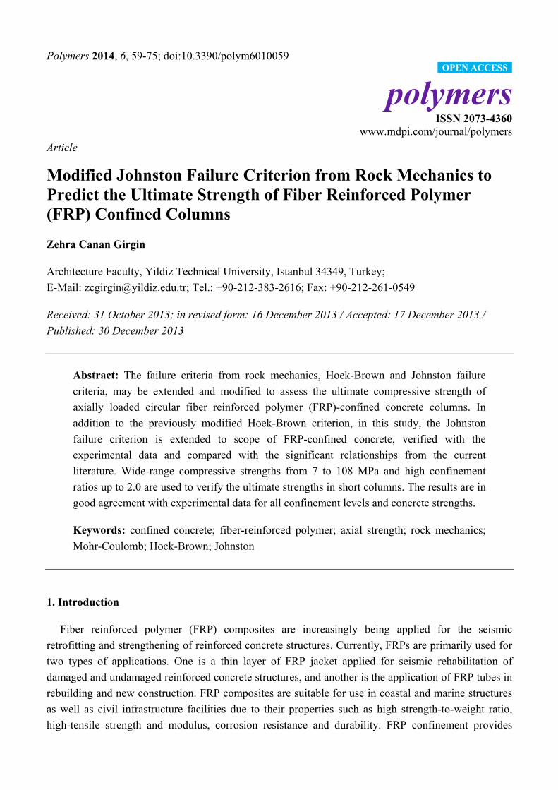
criteria [16], for FRP-confined concrete. The Mohr-Coulomb criterion is valid only in the compression
region [17], whereas Hoek-Brown’s and Johnston’s failure criteria from rock mechanics exist both in
compressive and tensile regions to complete it (Figure 1). Previously, in order to extend the scope to
concrete, the Hoek-Brown’s and Johnston’s criteria were successfully verified to predict the ultimate
strength in high strength (60–132 MPa) concrete specimens under active confining pressure [17]. More
recently, the Hoek-Brown criterion was applied to reinforced concrete and FRP- confined circular
columns by the author [18]. This study addresses the applicability of other failure criterion, the
Johnston failure criterion, from rock mechanics. The criterion is validated for FRP-confined circular
short columns through the wide-range experimental data (7 to 108 MPa) from the current literature.
The comparisons confirm the applicability of the Johnston failure criterion to FRP composites as well.
Figure 1. Mohr-Coulomb, Johnston and Hoek-Brown’s failure envelope to estimate the
ultimate strength under triaxial compression.
2. Literature Survey and Database
Considerable research has been devoted to FRP-confined circular columns and numerous models
have been proposed [1–4,11–14,18–26]. The common experimental data to predict ultimate (confined)
strength are especially in the range of 30 to 50 MPa [11,25–33]. In this study, a database involved in
short columns (L/D = 1.6 to 2.9, most of them are 2) [3,11,24–42] was deployed regarding the
confinement levels from 0.03 up to 2.0 by including AFRP, CFRP, and GFRP jacketing. The average
Polymers 2014, 6 61
value of nominally identical specimens in each test group was used to decrease scattering and error in
the analyses. In addition, the data from observed lateral stresses or coupon test results were used to
improve the reliability. In terms of concrete cylinder strength fco, the averaged database covers 116 data
for FRP-wrapped cylinders from 7 to 108 MPa [3,24–27,30–32,35–42] and 19 data for FRP tube encased
cylinders from 29.6 to 45.4 MPa [11,28,29,33,34]. In addition, 56 averaged data [6,14,23,43–45] from
17 to 80 MPa were used for calibration.
3. Overview to Confinement Models with FRP
Under triaxial compressive stresses, the columns are subjected to major compressive stresses σ1
uniformly applied along the axial axis of the column and lateral confining pressure σ3 (Figure 1). This
pressure may be provided by passive means such as steel (hoops, ties, spirals, jackets, etc.) and FRP
(sheets, tubes, etc.) confinement around the concrete core or actively through hydrostatic pressure. On
the contrary of steel, FRP behaves elastically until failure. The inward radial pressure increases with
the lateral expansion of the concrete, so that the assumption of constant confining pressure is no longer
valid. The models [7,8,46–48] developed for steel confinement may unsafely overestimate the strength
of FRP-confined columns.
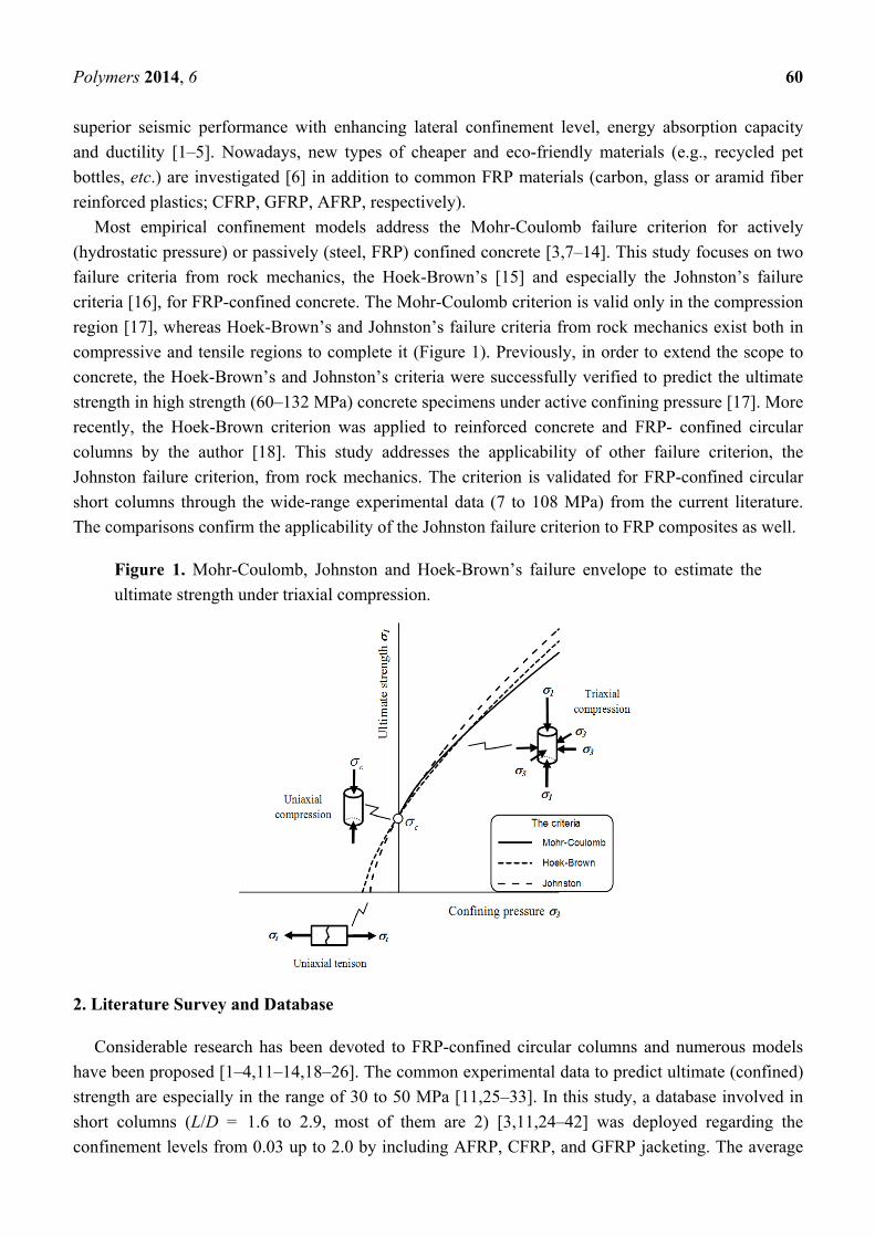
In FRP confined columns, the fibers are generally aligned primarily along the hoop direction to
provide the confinement of concrete while the fibers in the axial direction provide the flexural strength
and stiffness. While the concrete is stressed triaxially, the FRP jacket is loaded uniaxially and, at the
FRP-concrete interface, the confining radial pressure σ3 (Figure 2) develops by:
3
2 σσ frp
l
tf
D (1)
where t, D, σfrp denote the thickness of FRP, the diameter of concrete core and the hoop tensile
strength of FRP, respectively.
Figure 2. Scheme of confining action for (a) concrete; (b) Fiber reinforced polymer (FRP) composite.
The Mohr-Coulomb failure criterion frequently used for confined concrete is essentially based on
triaxial soil data:
1 3 1 32ccos 1 sin
σ σ , σ σ1 sin 1 sin
(2)
Polymers 2014, 6 62
here σ1 signifies the major principal stress at failure (ultimate strength), σ3 is the minor principal stress
(confining pressure), c is the cohesive strength of soil, and is the internal-friction angle. Unconfined
strength (fl = σ3 = 0) is defined as:
12 cos
σ1 sinco
cf
(3)
The positive effect of confinement on concrete cylinders was first observed and modelled by
Richart et al. [7] by defining the internal-friction angle as 37°. Then Goodman [49] suggested in
the range of 36°–45° for most of concrete strengths, Rochette and Labossière formulated and c [30].
The confinement effectiveness coefficient k is defined in terms of :
1 sin
1 sin
k
(4)
and Equation (2) may be expressed to assess the ultimate strength fcc of confined concrete:
cc co lf f k f (5)
and often in the following normalized form:
1cc l
co co
f fk
f f (6)
where fcc/fco is described as the strengthening ratio. Richart et al. [7] who suggested k value as 4.1
corresponding to = 37° and then many authors have widely used these forms [8–14].
Saatcioglu and Razvi [47] found that the coefficient k decreases with increasing confining pressure
by approaching a constant value in high lateral stresses. While Candappa et al. [50] proposed k = 5.3
for low confinement levels, Ansari and Li [10] found k = 2.6 for high confinement levels. Dahl [51]
has shown that the traditional value of k = 4.1 overestimates the ultimate strength for the confinement
ratios exceeding 0.5. For FRP-confined concrete, while some authors suggested a constant value for
k [6,14,22,52–54], according to other authors, k should be a function decreasing with the confinement
ratio [3,11–13,20,55].
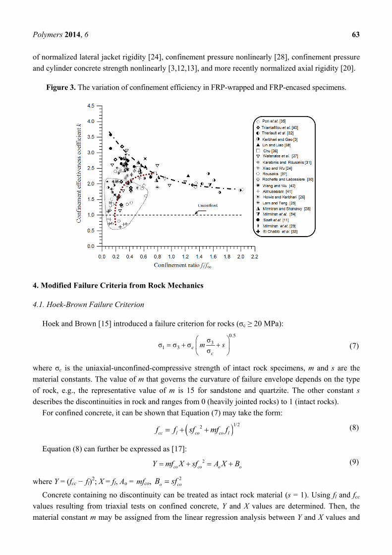
As a great number of relationships according to Mohr-Coulomb criterion have been proposed so far,
in this study, only the variation of k is displayed for FRP-wrapped or FRP tube encased specimens.
For the averaged database of this study, two significantly different cases are observed especially for
FRP-wrapped specimens (Figure 3). In the first case, a specific trend with a dashed line is under
consideration and while k value is high in low confinement levels it declines toward a constant value of
1.8 in high confinement levels. For the second case, there are data scattering in the confinement ratios
lower than about 0.7. It may be suggested that k has either a conservative value of about 2 or lower and
variable values within the dotted curve. The dotted line converges towards the first trend at medium
confinement levels. Spoelstra and Monti [13] previously defined lower effectiveness for fl/fco < 0.07
and expressed that the confinement effectiveness is never greater than 3 and that it reaches maximum
at about fl/fco < 0.3. According to Li [56], both insufficient coefficient and higher concrete strength
may lead to lower confinement effectiveness. Recently Teng et al. [57] defined fl/fco to be the product
of the confinement stiffness ratio and strain ratio. In the literature, k coefficient was expressed in terms
Polymers 2014, 6 63
of normalized lateral jacket rigidity [24], confinement pressure nonlinearly [28], confinement pressure
and cylinder concrete strength nonlinearly [3,12,13], and more recently normalized axial rigidity [20].
Figure 3. The variation of confinement efficiency in FRP-wrapped and FRP-encased specimens.
4. Modified Failure Criteria from Rock Mechanics
4.1. Hoek-Brown Failure Criterion
Hoek and Brown [15] introduced a failure criterion for rocks (σc ≥ 20 MPa):
0.5
31 3
σσ σ σ
σcc
m s
(7)
where σc is the uniaxial-unconfined-compressive strength of intact rock specimens, m and s are the
material constants. The value of m that governs the curvature of failure envelope depends on the type
of rock, e.g., the representative value of m is 15 for sandstone and quartzite. The other constant s
describes the discontinuities in rock and ranges from 0 (heavily jointed rocks) to 1 (intact rocks).
For confined concrete, it can be shown that Equation (7) may take the form:
1/22cc l co co lf f sf mf f (8)
Equation (8) can further be expressed as [17]:
2co co o oY mf X sf A X B (9)
where Y = (fcc − fl)2; X = fl, Ao = mfco,
2o coB sf
Concrete containing no discontinuity can be treated as intact rock material (s = 1). Using fl and fcc
values resulting from triaxial tests on confined concrete, Y and X values are determined. Then, the
material constant m may be assigned from the linear regression analysis between Y and X values and
Polymers 2014, 6 64
thus the failure envelope is described. In the pure tension case fcc = 0 → fl = −ft where ft is the
uniaxial-direct-tensile strength (Figure 1).
In this failure criterion adapted from rock mechanics, the first step is to precisely predict m constant.
The predicted m values regarding the active and FRP confinement are displayed according to the
strength ranges in Table 1. For FRP confined concrete, while m is 4.8 to 3.3 in normal strength
range (20 to 40 MPa), it has a very low value (m = 0.1) in the high-strength concrete especially over
80 MPa [18]. Meanwhile, it should be mentioned for cylinder strengths over 108 MPa the accuracy of
prediction may be decreased due to very low and constant m coefficient. As for actively confined
concrete, the highest m value (m = 13) is under consideration [17] and approaches to the lower
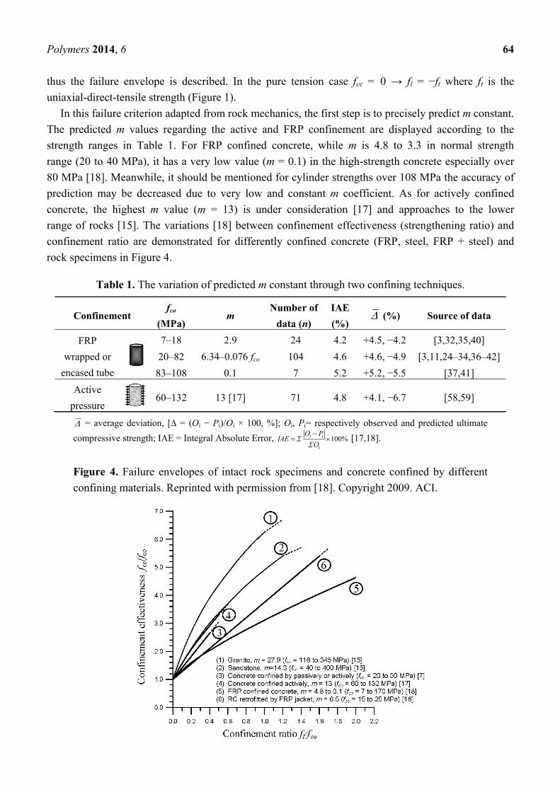
range of rocks [15]. The variations [18] between confinement effectiveness (strengthening ratio) and
confinement ratio are demonstrated for differently confined concrete (FRP, steel, FRP + steel) and
rock specimens in Figure 4.
Table 1. The variation of predicted m constant through two confining techniques.
Confinement fco
(MPa) m
Number of
data (n)
IAE
(%) (%) Source of data
FRP
wrapped or
encased tube
7–18 2.9 24 4.2 +4.5, −4.2 [3,32,35,40]
20–82 6.34–0.076 fco 104 4.6 +4.6, −4.9 [3,11,24–34,36–42]
83–108 0.1 7 5.2 +5.2, −5.5 [37,41]
Active
pressure 60–132 13 [17] 71 4.8 +4.1, −6.7 [58,59]
= average deviation, [∆ = (Oi − Pi)/Oi × 100, %]; Oi, Pi= respectively observed and predicted ultimate
compressive strength; IAE = Integral Absolute Error, 100%i i
i
O PIAE
O
[17,18].
Figure 4. Failure envelopes of intact rock specimens and concrete confined by different
confining materials. Reprinted with permission from [18]. Copyright 2009. ACI.
Polymers 2014, 6 65
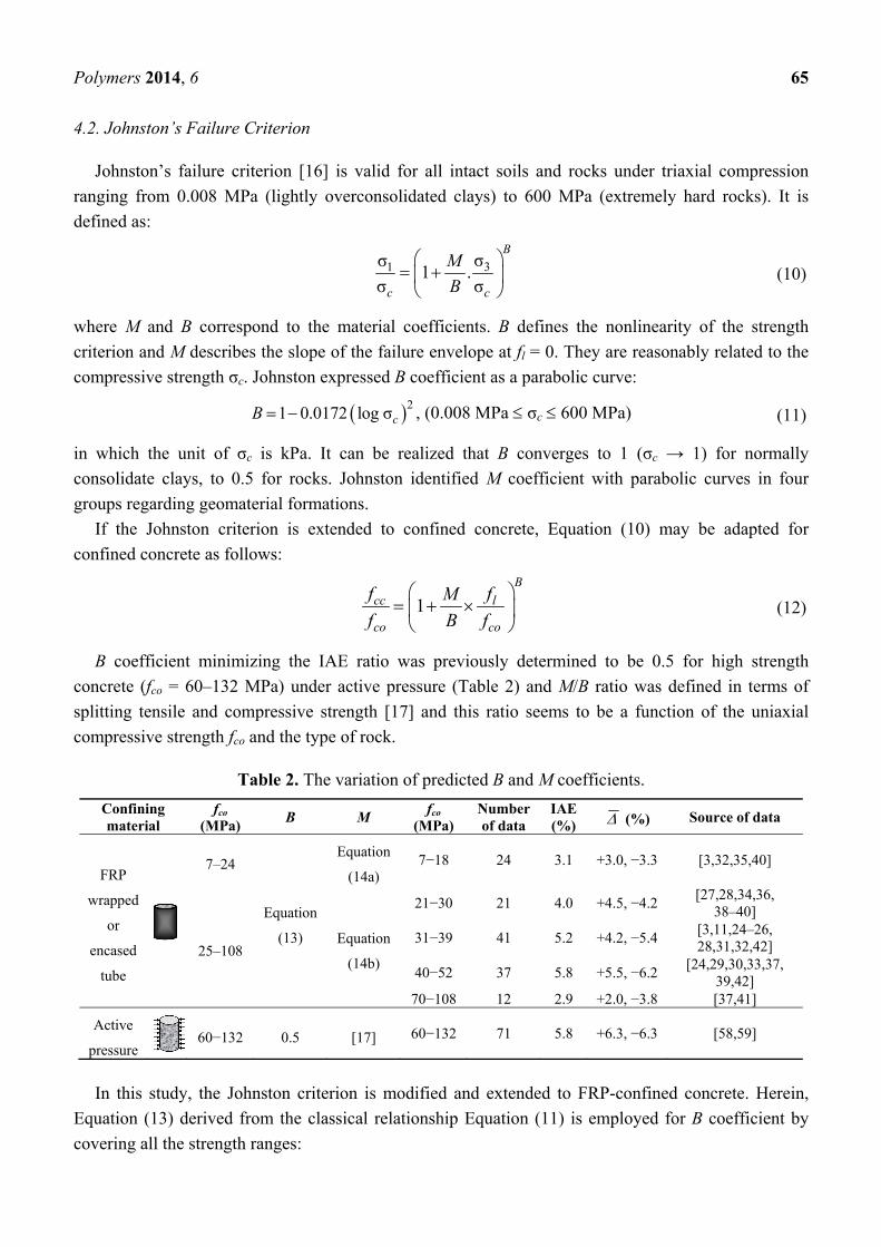
4.2. Johnston’s Failure Criterion
Johnston’s failure criterion [16] is valid for all intact soils and rocks under triaxial compression
ranging from 0.008 MPa (lightly overconsolidated clays) to 600 MPa (extremely hard rocks). It is
defined as:
31 σσ1 .
σ σ
B
c c
M
B
(10)
where M and B correspond to the material coefficients. B defines the nonlinearity of the strength
criterion and M describes the slope of the failure envelope at fl = 0. They are reasonably related to the
compressive strength σc. Johnston expressed B coefficient as a parabolic curve:
21 0.0172 log σcB , (0.008 MPa σc 600 MPa) (11)
in which the unit of σc is kPa. It can be realized that B converges to 1 (σc → 1) for normally
consolidate clays, to 0.5 for rocks. Johnston identified M coefficient with parabolic curves in four
groups regarding geomaterial formations.
If the Johnston criterion is extended to confined concrete, Equation (10) may be adapted for
confined concrete as follows:
1B
cc l
co co
f fM
f B f
(12)
B coefficient minimizing the IAE ratio was previously determined to be 0.5 for high strength
concrete (fco = 60–132 MPa) under active pressure (Table 2) and M/B ratio was defined in terms of
splitting tensile and compressive strength [17] and this ratio seems to be a function of the uniaxial
compressive strength fco and the type of rock.
Table 2. The variation of predicted B and M coefficients.
Confining material
fco (MPa)
B M fco
(MPa)Number of data
IAE (%) (%) Source of data
FRP
wrapped
or
encased
tube
7–24
Equation
(13)
Equation
(14a) 7−18 24 3.1 +3.0, −3.3 [3,32,35,40]
25–108 Equation
(14b)
21−30 21 4.0 +4.5, −4.2 [27,28,34,36,
38–40]
31−39 41 5.2 +4.2, −5.4 [3,11,24–26, 28,31,32,42]
40−52 37 5.8 +5.5, −6.2 [24,29,30,33,37,
39,42] 70−108 12 2.9 +2.0, −3.8 [37,41]
Active
pressure 60−132 0.5 [17] 60−132 71 5.8 +6.3, −6.3 [58,59]
In this study, the Johnston criterion is modified and extended to FRP-confined concrete. Herein,
Equation (13) derived from the classical relationship Equation (11) is employed for B coefficient by
covering all the strength ranges:
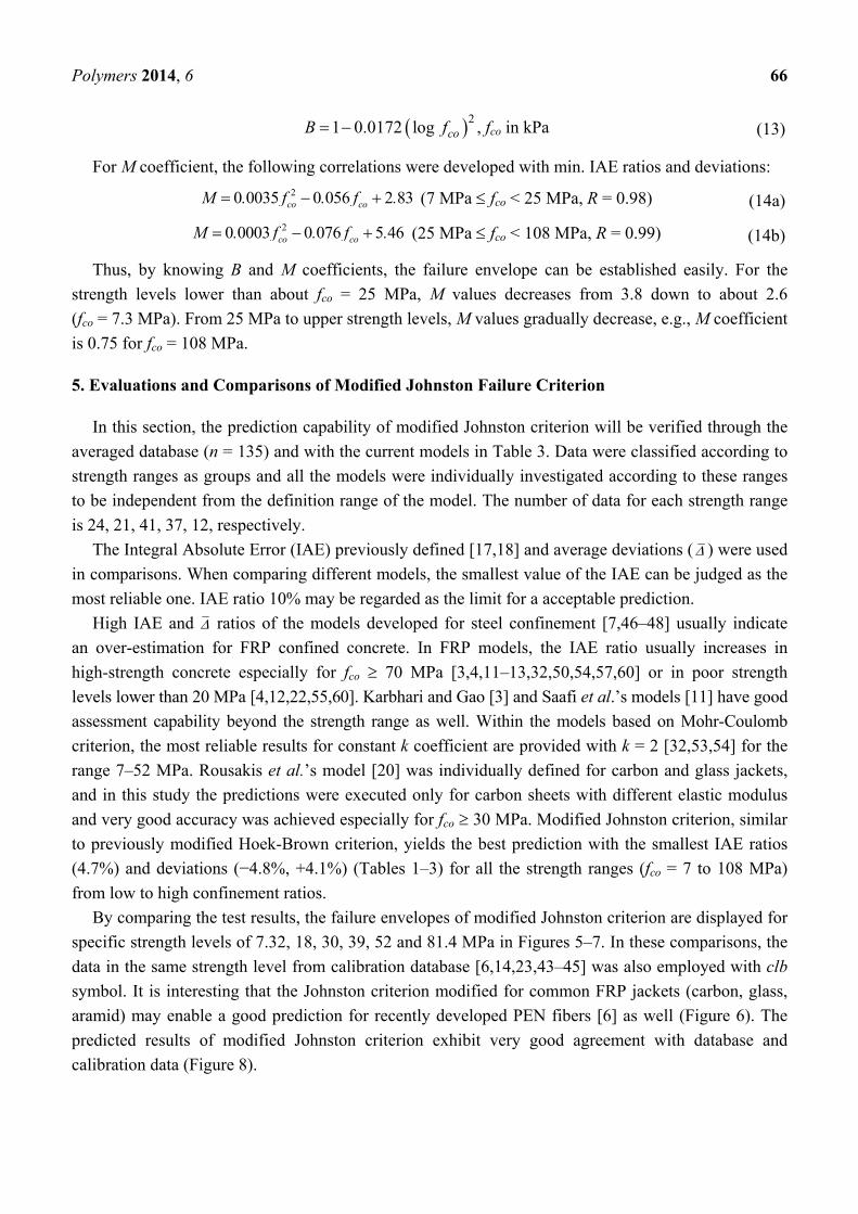
Polymers 2014, 6 66
21 0.0172 log coB f , fco in kPa (13)
For M coefficient, the following correlations were developed with min. IAE ratios and deviations: 20 0035 0 056 2 83co coM . f . f . (7 MPa fco < 25 MPa, R = 0.98) (14a)
20 0003 0 076 5 46co coM . f . f . (25 MPa fco < 108 MPa, R = 0.99) (14b)
Thus, by knowing B and M coefficients, the failure envelope can be established easily. For the
strength levels lower than about fco = 25 MPa, M values decreases from 3.8 down to about 2.6
(fco = 7.3 MPa). From 25 MPa to upper strength levels, M values gradually decrease, e.g., M coefficient
is 0.75 for fco = 108 MPa.
5. Evaluations and Comparisons of Modified Johnston Failure Criterion
In this section, the prediction capability of modified Johnston criterion will be verified through the
averaged database (n = 135) and with the current models in Table 3. Data were classified according to
strength ranges as groups and all the models were individually investigated according to these ranges
to be independent from the definition range of the model. The number of data for each strength range
is 24, 21, 41, 37, 12, respectively.
The Integral Absolute Error (IAE) previously defined [17,18] and average deviations ( ) were used
in comparisons. When comparing different models, the smallest value of the IAE can be judged as the
most reliable one. IAE ratio 10% may be regarded as the limit for a acceptable prediction.
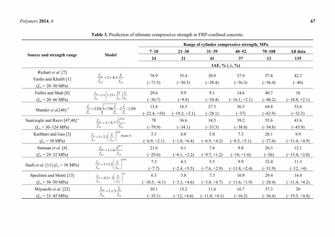
High IAE and ratios of the models developed for steel confinement [7,46–48] usually indicate
an over-estimation for FRP confined concrete. In FRP models, the IAE ratio usually increases in
high-strength concrete especially for fco 70 MPa [3,4,11–13,32,50,54,57,60] or in poor strength
levels lower than 20 MPa [4,12,22,55,60]. Karbhari and Gao [3] and Saafi et al.’s models [11] have good
assessment capability beyond the strength range as well. Within the models based on Mohr-Coulomb
criterion, the most reliable results for constant k coefficient are provided with k = 2 [32,53,54] for the
range 7–52 MPa. Rousakis et al.’s model [20] was individually defined for carbon and glass jackets,
and in this study the predictions were executed only for carbon sheets with different elastic modulus
and very good accuracy was achieved especially for fco 30 MPa. Modified Johnston criterion, similar
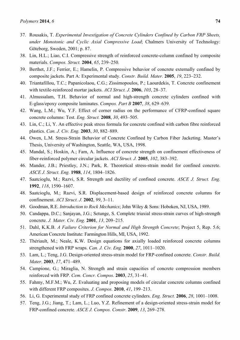
to previously modified Hoek-Brown criterion, yields the best prediction with the smallest IAE ratios
(4.7%) and deviations (−4.8%, +4.1%) (Tables 1–3) for all the strength ranges (fco = 7 to 108 MPa)
from low to high confinement ratios.
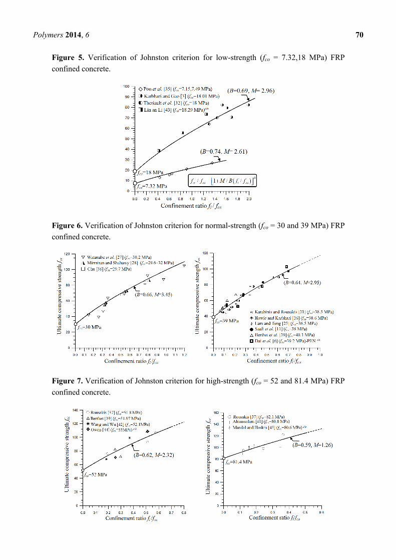
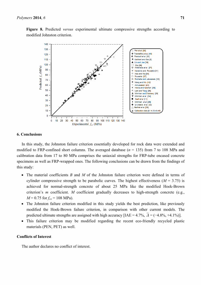
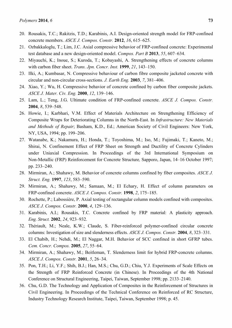
By comparing the test results, the failure envelopes of modified Johnston criterion are displayed for
specific strength levels of 7.32, 18, 30, 39, 52 and 81.4 MPa in Figures 5–7. In these comparisons, the
data in the same strength level from calibration database [6,14,23,43–45] was also employed with clb
symbol. It is interesting that the Johnston criterion modified for common FRP jackets (carbon, glass,
aramid) may enable a good prediction for recently developed PEN fibers [6] as well (Figure 6). The
predicted results of modified Johnston criterion exhibit very good agreement with database and
calibration data (Figure 8).
Polymers 2014, 6 67
Table 3. Prediction of ultimate compressive strength in FRP-confined concrete.
Source and strength range Model
Range of cylinder compressive strength, MPa
7–18 21–30 31–39 40–52 70–108 All data
24 21 41 37 12 135
IAE, % ( , %)
Richart et al. [7]
Fardis and Khalili [1]
(fco = 20–50 MPa)
1 4.1cc l
co co
f f
f f 78.9
(−71.5)
35.4
(−30.3)
30.9
(−28.4)
37.9
(−36.3)
57.8
(−56.4)
42.3
(−40)
Fafitis and Shah [8]
(fco = 20–66 MPa)
211 1.15cc l
co co co
f f
f f f
29.6
(−36.7)
9.9
(−9.8)
9.1
(−10.4)
14.6
(−16.1, +2.1)
40.7
(−40.2)
18
(−18.8, +2.1)
Mander et al.[46] a 2.254 1 7.94 2 1.254cc l l
co co co
f f f
f f f
13.6
(−22.4, +10)
16.5
(−19.2, +3.1)
27.5
(−28.1)
36.5
(−37)
64.8
(−63.9)
33.6
(−32.5)
Saatcioglu and Razvi [47,48] a
(fco = 30–124 MPa)
0.83
1 6.7cc l
co co
f f
f f
78
(−79.9)
36.6
(−34.1)
34.5
(−33.3)
39.2
(−38.8)
55.6
(−54.8)
43.6
(−43.9)
Karbhari and Gao [3]
(fco = 38 MPa)
0.87
1 2.1cc l
co co
f f
f f
Model II 5.3
(−6.9, +2.1)
6.0
(−1.0, +6.4)
5.0
(−6.9, +4.2)
7.3
(−8.5, +5.1)
28.1
(−27.6)
9.9
(−11.4, +4.9)
Samaan et al. [4]
(fco = 29–32 MPa)
0.7
1 6cc l
co co
f f
f f 21.6
(−29.6)
4.1
(−6.1, +2.2)
7.6
(−9.7, +1.2)
9.8
(−10, +1.6)
26.3
(−26)
12.1
(−15.4, +2.0)
Saafi et al. [11] (fco = 38 MPa) 0.84
1 2.2cc l
co co
f f
f f
7.3
(−7.7)
4.3
(−2.4, +5.5)
5.5
(−7.6, +2.9)
9.9
(−11.8, +2.4)
32.4
(−31.9)
11.3
(−12, +4)
Spoelstra and Monti [13]
(fco = 30–50 MPa)
0.5
0.2 3cc l
co co
f f
f f
6.5
(−10.5, +4.1)
3.8
(−3.1, +4.6)
7.3
(−5.8, +4.7)
10.9
(−11.6, +1.9)
29.4
(−28.4)
14.4
(−11.4, +4.2)
Miyauchi et al. [22]
(fco = 33–45 MPa)1 3cc l
co co
f f
f f 39.1
(−35.1)
15.2
(−12, +4.6)
11.6
(−11.8, +4.1)
16.7
(−16.2)
37.3
(−36.4)
20
(−19.5, +4.4)
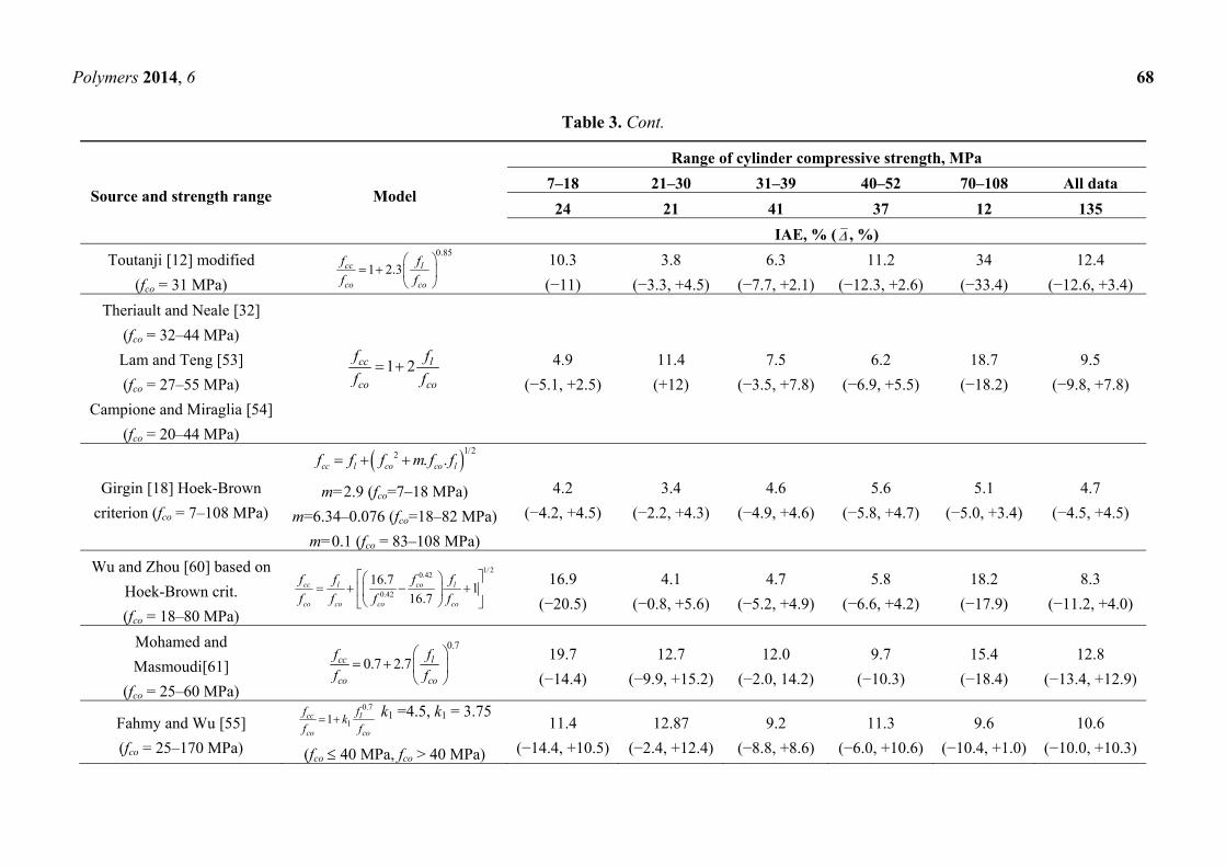
Polymers 2014, 6 68
Table 3. Cont.
Source and strength range Model
Range of cylinder compressive strength, MPa
7–18 21–30 31–39 40–52 70–108 All data
24 21 41 37 12 135
IAE, % ( , %)
Toutanji [12] modified
(fco = 31 MPa)
0.85
1 2.3cc l
co co
f f
f f
10.3
(−11)
3.8
(−3.3, +4.5)
6.3
(−7.7, +2.1)
11.2
(−12.3, +2.6)
34
(−33.4)
12.4
(−12.6, +3.4)
Theriault and Neale [32]
(fco = 32–44 MPa)
Lam and Teng [53]
(fco = 27–55 MPa)
Campione and Miraglia [54]
(fco = 20–44 MPa)
1 2cc l
co co
f f
f f 4.9
(−5.1, +2.5)
11.4
(+12)
7.5
(−3.5, +7.8)
6.2
(−6.9, +5.5)
18.7
(−18.2)
9.5
(−9.8, +7.8)
Girgin [18] Hoek-Brown
criterion (fco = 7–108 MPa)
1/22 . . cc l co co lf f f m f f
m=2.9 (fco=7–18 MPa)
m=6.34–0.076 (fco=18–82 MPa)
m=0.1 (fco = 83–108 MPa)
4.2
(−4.2, +4.5)
3.4
(−2.2, +4.3)
4.6
(−4.9, +4.6)
5.6
(−5.8, +4.7)
5.1
(−5.0, +3.4)
4.7
(−4.5, +4.5)
Wu and Zhou [60] based on
Hoek-Brown crit.
(fco = 18–80 MPa)
1/20.42
0.42
16.71
16.7cc l co l
co co co co
f f f f
f f f f
16.9
(−20.5)
4.1
(−0.8, +5.6)
4.7
(−5.2, +4.9)
5.8
(−6.6, +4.2)
18.2
(−17.9)
8.3
(−11.2, +4.0)
Mohamed and
Masmoudi[61]
(fco = 25–60 MPa)
0.7
0.7 2.7
cc l
co co
f f
f f 19.7
(−14.4)
12.7
(−9.9, +15.2)
12.0
(−2.0, 14.2)
9.7
(−10.3)
15.4
(−18.4)
12.8
(−13.4, +12.9)
Fahmy and Wu [55]
(fco = 25–170 MPa)
0.7
11 cc l
co co
f fk
f f k1 =4.5, k1 = 3.75
(fco 40 MPa, fco > 40 MPa)
11.4
(−14.4, +10.5)
12.87
(−2.4, +12.4)
9.2
(−8.8, +8.6)
11.3
(−6.0, +10.6)
9.6
(−10.4, +1.0)
10.6
(−10.0, +10.3)
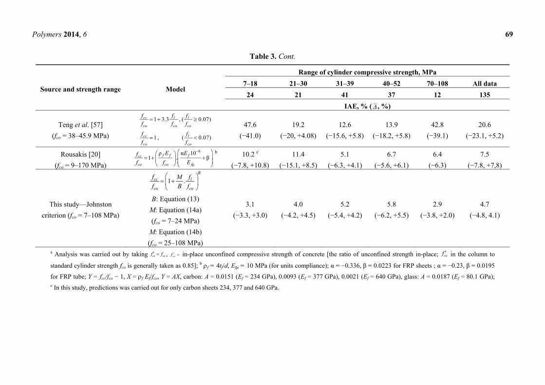
Polymers 2014, 6 69
Table 3. Cont.
Source and strength range Model
Range of cylinder compressive strength, MPa
7–18 21–30 31–39 40–52 70–108 All data
24 21 41 37 12 135
IAE, % ( , %)
Teng et al. [57]
(fco = 38–45.9 MPa)
1 3.3 , ( 0.07)
1 , ( 0.07)
cc l l
co co co
cc l
co co
f f f
f f f
f f
f f
47.6
(−41.0)
19.2
(−20, +4.08)
12.6
(−15.6, +5.8)
13.9
(−18.2, +5.8)
42.8
(−39.1)
20.6
(−23.1, +5.2)
Rousakis [20]
(fco = 9–170 MPa)
6
μ
ρ α 101 . βf f fcc
co co f
E Ef
f f E
b 10.2 c
(−7.8, +10.8)
11.4
(−15.1, +8.5)
5.1
(−6.3, +4.1)
6.7
(−5.6, +6.1)
6.4
(−6.3)
7.5
(−7.8, +7,8)
This study—Johnston
criterion (fco = 7–108 MPa)
1 .B
cc l
co co
f fM
f B f
B: Equation (13)
M: Equation (14a)
(fco = 7–24 MPa)
M: Equation (14b)
(fco = 25–108 MPa)
3.1
(−3.3, +3.0)
4.0
(−4.2, +4.5)
5.2
(−5.4, +4.2)
5.8
(−6.2, +5.5)
2.9
(−3.8, +2.0)
4.7
(−4.8, 4.1)
a Analysis was carried out by taking co cof f , cof in-place unconfined compressive strength of concrete [the ratio of unconfined strength in-place; cof in the column to
standard cylinder strength fco is generally taken as 0.85]; b f = 4tf/d, Ef = 10 MPa (for units compliance); α = −0.336, β = 0.0223 for FRP sheets ; α = −0.23, β = 0.0195
for FRP tube; Y = fcc/fco − 1, X = f Ef/fco, Y = AX, carbon: A = 0.0151 (Ef = 234 GPa), 0.0093 (Ef = 377 GPa), 0.0021 (Ef = 640 GPa), glass: A = 0.0187 (Ef = 80.1 GPa); c In this study, predictions was carried out for only carbon sheets 234, 377 and 640 GPa.
Polymers 2014, 6 70
Figure 5. Verification of Johnston criterion for low-strength (fco = 7.32,18 MPa) FRP
confined concrete.
Figure 6. Verification of Johnston criterion for normal-strength (fco = 30 and 39 MPa) FRP
confined concrete.
Figure 7. Verification of Johnston criterion for high-strength (fco = 52 and 81.4 MPa) FRP
confined concrete.
Polymers 2014, 6 71
Figure 8. Predicted versus experimental ultimate compressive strengths according to
modified Johnston criterion.
6. Conclusions
In this study, the Johnston failure criterion essentially developed for rock data were extended and
modified to FRP-confined short columns. The averaged database (n = 135) from 7 to 108 MPa and
calibration data from 17 to 80 MPa comprises the uniaxial strengths for FRP-tube encased concrete
specimens as well as FRP-wrapped ones. The following conclusions can be drawn from the findings of
this study:
The material coefficients B and M of the Johnston failure criterion were defined in terms of
cylinder compressive strength to be parabolic curves. The highest effectiveness (M = 3.75) is
achieved for normal-strength concrete of about 25 MPa like the modified Hoek-Brown
criterion’s m coefficient. M coefficient gradually decreases to high-strength concrete (e.g.,
M = 0.75 for fco = 108 MPa).
The Johnston failure criterion modified in this study yields the best prediction, like previously
modified the Hoek-Brown failure criterion, in comparison with other current models. The
predicted ultimate strengths are assigned with high accuracy [IAE = 4.7%, = (−4.8%, +4.1%)].
This failure criterion may be modified regarding the recent eco-friendly recycled plastic
materials (PEN, PET) as well.
Conflicts of Interest
The author declares no conflict of interest.

Polymers 2014, 6 72
References
1. Fardis, M.N.; Khalili, H. Concrete encased in fiberglass-reinforced plastic. ACI Struct. J. 1981,
78, 440–445.
2. Saadatmanesh, H.; Ehsani, M.R.; Li, M.W. Strength and ductility of concrete columns externally
reinforced with fiber composite straps. ACI Struct. J. 1994, 91, 434–447.
3. Karbhari, V.M.; Gao, Y. Composite jacketed concrete under uniaxial compression—Verification
of simple design equations. ASCE J. Mater. Civ. Eng. 1997, 9, 185–193.
4. Samaan, M.; Mirmiran, A.; Shahawy, M. Modeling of concrete confined by fiber composites.
ASCE J. Struct. Eng. 1998, 124, 1025–1031.
5. Ozbakkaloglu, T.; Akın, E. Behavior of FRP-confined normal- and high-strength concrete under
cyclic axial compression. ASCE J. Compos. Constr. 2012, 16, 451–463.
6. Dai, J.G.; Bai, Y.L.; Teng, J.G. Behaviour and modeling of concrete confined with FRP
composites of large deformability. ASCE J. Compos. Constr. 2011, 15, 963–973.
7. Richart, E.; Brandtzaeg, A.; Brown, R.L. Failure of Plain and Spirally Reinforced Concrete in
Compression; Bulletin 190; University of Illinois, Engineering Experimental Station: Champaign,
IL, USA, 1929.
8. Fafitis, A.; Shah, S.P. Lateral Reinforcement for High-Strength Concrete Columns. In High-Strength
Concrete; ACI SP-87; American Concrete Institute: Farmington Hills, MI, USA, 1985, pp. 213–232.
9. Razvi, S.R.; Saatcioglu, M. Confinement model for high-strength concrete. ASCE J. Struct. Eng.
1999, 125, 3281–3289.
10. Ansari, F.; Li, Q. High strength concrete subjected to triaxial compression. ACI Mater. J. 1998,
95, 747–755.
11. Saafi, M.; Toutanji, H.A.; Li, Z. Behaviour of concrete columns confined with fiber reinforced
polymer tubes. ACI Mater. J. 1999, 96, 500–509.
12. Toutanji, H.A. Stress-strain characteristics of concrete columns externally confined with advanced
fibre composite sheets. ACI Mater. J. 1999, 96, 397–402.
13. Spoelstra, M.R.; Monti, G. FRP-confined concrete model. ASCE J. Compos. Constr. 1999, 3,
143–150.
14. Jiang, T.; Teng, J.G. Analysis-oriented stress-strain models for FRP-confined concrete. Eng. Struct.
2007, 29, 2968–2986.
15. Hoek, E.; Kaiser, P.K.; Bawden, W.F. Support of Underground Excavations in Hard Rock;
A.A. Balkema: Rotterdam, Netherlands, 1995; p. 215.
16. Johnston, I.W. Comparison of two strength crieria for intact rock. ASCE J. Geotech. Eng. Div.
1985, 111, 1449–1454.
17. Girgin, Z.C.; Arıoglu, N.; Arıoglu, E. Evaluation of strength criteria for very-high-strength
concretes under triaxial compression. ACI Struct. J. 2007, 104, 278–284.
18. Girgin, Z.C. A modified failure criterion to predict ultimate strength of circular columns confined
by different materials. ACI Struct. J. 2009, 106, 800–809.
19. De Lorenzis, L.; Tepfers, R. Comparative study of models on confinement of concrete cylinders
with fiber-reinforced polymer composites. ASCE J. Compos. Constr. 2003, 7, 219–237.
Polymers 2014, 6 73
20. Rousakis, T.C.; Rakitzis, T.D.; Karabinis, A.I. Design-oriented strength model for FRP-confined
concrete members. ASCE J. Compos. Constr. 2012, 16, 615–625.
21. Ozbakkaloglu, T.; Lim, J.C. Axial compressive behavior of FRP-confined concrete: Experimental
test database and a new design-oriented model. Compos. Part B 2013, 55, 607–634.
22. Miyauchi, K.; Inoue, S.; Kuroda, T.; Kobayashi, A. Strengthening effects of concrete columns
with carbon fiber sheet. Trans. Jpn. Concr. Inst. 1999, 21, 143–150.
23. Ilki, A.; Kumbasar, N. Compressive behaviour of carbon fibre composite jacketed concrete with
circular and non-circular cross-sections. J. Earth Eng. 2003, 7, 381–406.
24. Xiao, Y.; Wu, H. Compressive behavior of concrete confined by carbon fiber composite jackets.
ASCE J. Mater. Civ. Eng. 2000, 12, 139–146.
25. Lam, L.; Teng, J.G. Ultimate condition of FRP-confined concrete. ASCE J. Compos. Constr.
2004, 8, 539–548.
26. Howie, I.; Karbhari, V.M. Effect of Materials Architecture on Strengthening Efficiency of
Composite Wraps for Deteriorating Columns in the North-East. In Infrastructure: New Materials
and Methods of Repair; Basham, K.D., Ed.; American Society of Civil Engineers: New York,
NY, USA, 1994; pp. 199–206.
27. Watanabe, K.; Nakamura, H.; Honda, T.; Toyoshima, M.; Iso, M.; Fujimaki, T.; Kaneto, M.;
Shirai, N. Confinement Effect of FRP Sheet on Strength and Ductility of Concrete Cylinders
under Uniaxial Compression. In Proceedings of the 3rd International Symposium on
Non-Metallic (FRP) Reinforcement for Concrete Structure, Sapporo, Japan, 14–16 October 1997;
pp. 233–240.
28. Mirmiran, A.; Shahawy, M. Behavior of concrete columns confined by fiber composites. ASCE J.
Struct. Eng. 1997, 123, 583–590.
29. Mirmiran, A.; Shahawy, M.; Samaan, M.; El Echary, H. Effect of column parameters on
FRP-confined concrete. ASCE J. Compos. Constr. 1998, 2, 175–185.
30. Rochette, P.; Labossière, P. Axial testing of rectangular column models confined with composites.
ASCE J. Compos. Constr. 2000, 4, 129–136.
31. Karabinis, A.I.; Rousakis, T.C. Concrete confined by FRP material: A plasticity approach.
Eng. Struct. 2002, 24, 923–932.
32. Thériault, M.; Neale, K.W.; Claude, S. Fiber-reinforced polymer-confined circular concrete
columns: Investigation of size and slenderness effects. ASCE J. Compos. Constr. 2004, 8, 323–331.
33. El Chabib, H.; Nehdi, M.; El Naggar, M.H. Behavior of SCC confined in short GFRP tubes.
Cem. Concr. Compos. 2005, 27, 55–64.
34. Mirmiran, A.; Shahawy, M.; Beitleman, T. Slenderness limit for hybrid FRP-concrete columns.
ASCE J. Compos. Constr. 2001, 5, 26–34.
35. Pon, T.H.; Li, Y.F.; Shih, B.J.; Han, M.S.; Chu, G.D.; Chiu, Y.J. Experiments of Scale Effects on
the Strength of FRP Reinforced Concrete (in Chinese). In Proceedings of the 4th National
Conference on Structural Engineering, Taipei, Taiwan, September 1998; pp. 2133–2140.
36. Chu, G.D. The Technology and Application of Composites in the Reinforcement of Structures in
Civil Engineering. In Proceedings of the Technical Conference on Reinforced of RC Structure,
Industry Technology Research Institute, Taipei, Taiwan, September 1998; p. 45.
Polymers 2014, 6 74
37. Rousakis, T. Experimental Investigation of Concrete Cylinders Confined by Carbon FRP Sheets,
under Monotonic and Cyclic Axial Compressive Load; Chalmers University of Technology:
Göteborg, Sweden, 2001; p. 87.
38. Lin, H.L.; Liao, C.I. Compressive strength of reinforced concrete-column confined by composite
materials. Compos. Struct. 2004, 65, 239–250.
39. Berthet, J.F.; Ferrier, E.; Hamelin, P. Compressive behavior of concrete externally confined by
composite jackets. Part A: Experimental study. Constr. Build. Mater. 2005, 19, 223–232.
40. Triantafillou, T.C.; Papanicolaou, C.G.; Zissimopoulos, P.; Laourdekis, T. Concrete confinement
with textile-reinforced mortar jackets. ACI Struct. J. 2006, 103, 28–37.
41. Almussalam, T.H. Behavior of normal and high-strength concrete cylinders confined with
E-glass/epoxy composite laminates. Compos. Part B 2007, 38, 629–639.
42. Wang, L.M.; Wu, Y.F. Effect of corner radius on the performance of CFRP-confined square
concrete columns: Test. Eng. Struct. 2008, 30, 493–505.
43. Lin, C.; Li, Y. An effective peak stress formula for concrete confined with carbon fibre reinforced
plastics. Can. J. Civ. Eng. 2003, 30, 882–889.
44. Owen, L.M. Stress-Strain Behavior of Concrete Confined by Carbon Fiber Jacketing. Master’s
Thesis, University of Washington, Seattle, WA, USA, 1998.
45. Mandal, S.; Hoskin, A.; Fam, A. Influence of concrete strength on confinement effectiveness of
fiber-reinforced polymer circular jackets. ACI Struct. J. 2005, 102, 383–392.
46. Mander, J.B.; Priestley, J.N.; Park, R. Theoretical stress-strain model for confined concrete.
ASCE J. Struct. Eng. 1988, 114, 1804–1826.
47. Saatcioglu, M.; Razvi, S.R. Strength and ductility of confined concrete. ASCE J. Struct. Eng.
1992, 118, 1590–1607.
48. Saatcioglu, M.; Razvi, S.R. Displacement-based design of reinforced concrete columns for
confinement. ACI Struct. J. 2002, 99, 3–11.
49. Goodman, R.E. Introduction to Rock Mechanics; John Wiley & Sons: Hoboken, NJ, USA, 1989.
50. Candappa, D.C.; Sanjayan, J.G.; Setunge, S. Complete triaxial stress-strain curves of high-strength
concrete. J. Mater. Civ. Eng. 2001, 13, 209–215.
51. Dahl, K.K.B. A Failure Criterion for Normal and High Strength Concrete; Project 5, Rep. 5.6;
American Concrete Institute: Farmington Hills, MI, USA, 1992.
52. Thériault, M.; Neale, K.W. Design equations for axially loaded reinforced concrete columns
strengthened with FRP wraps. Can. J. Civ. Eng. 2000, 27, 1011–1020.
53. Lam, L.; Teng, J.G. Design-oriented stress-strain model for FRP-confined concrete. Constr. Build.
Mater. 2003, 17, 471–489.
54. Campione, G.; Miraglia, N. Strength and strain capacities of concrete compression members
reinforced with FRP. Cem. Concr. Compos. 2003, 25, 31–41.
55. Fahmy, M.F.M.; Wu, Z. Evaluating and proposing models of circular concrete columns confined
with different FRP composites. J. Compos. 2010, 41, 199–213.
56. Li, G. Experimental study of FRP confined concrete cylinders. Eng. Struct. 2006, 28, 1001–1008.
57. Teng, J.G.; Jiang, T.; Lam, L.; Luo, Y.Z. Refinement of a design-oriented stress-strain model for
FRP-confined concrete. ASCE J. Compos. Constr. 2009, 13, 269–278.
Polymers 2014, 6 75
58. Xie, J.; Elwi, A.E.; MacGregor, J.G. Mechanical properties of three high-strength concretes
containing silica fume. ACI Mater. J. 1995, 92, 135–145.
59. Attard, M.M.; Setunge, S. Stress-strain relationship of confined and unconfined concrete.
ACI Mater. J. 1996, 93, 432–442.
60. Wu, Y.F.; Zhou, Y. Unified strength model based on Hoek-Brown failure criterion for circular
and square concrete columns confined by FRP. ASCE J. Compos. Constr. 2010, 14, 175–184.
61. Mohamed, H.; Masmoudi, R. Axial load capacity of concrete-filled FRP tube columns:
Experimental versus predictions. ASCE J. Compos. Constr. 2010, 14, 231–243.
© 2013 by the authors; licensee MDPI, Basel, Switzerland. This article is an open access article
distributed under the terms and conditions of the Creative Commons Attribution license
(http://creativecommons.org/licenses/by/3.0/).