Embed Size (px)
Citation preview
Front Non-Drive Steering AxlesEssieux avant directeurs non moteurs
Issued 05-03Edité Mai-03
Maintenance Manual 2Manuel de maintenance 2
TM
FS-25
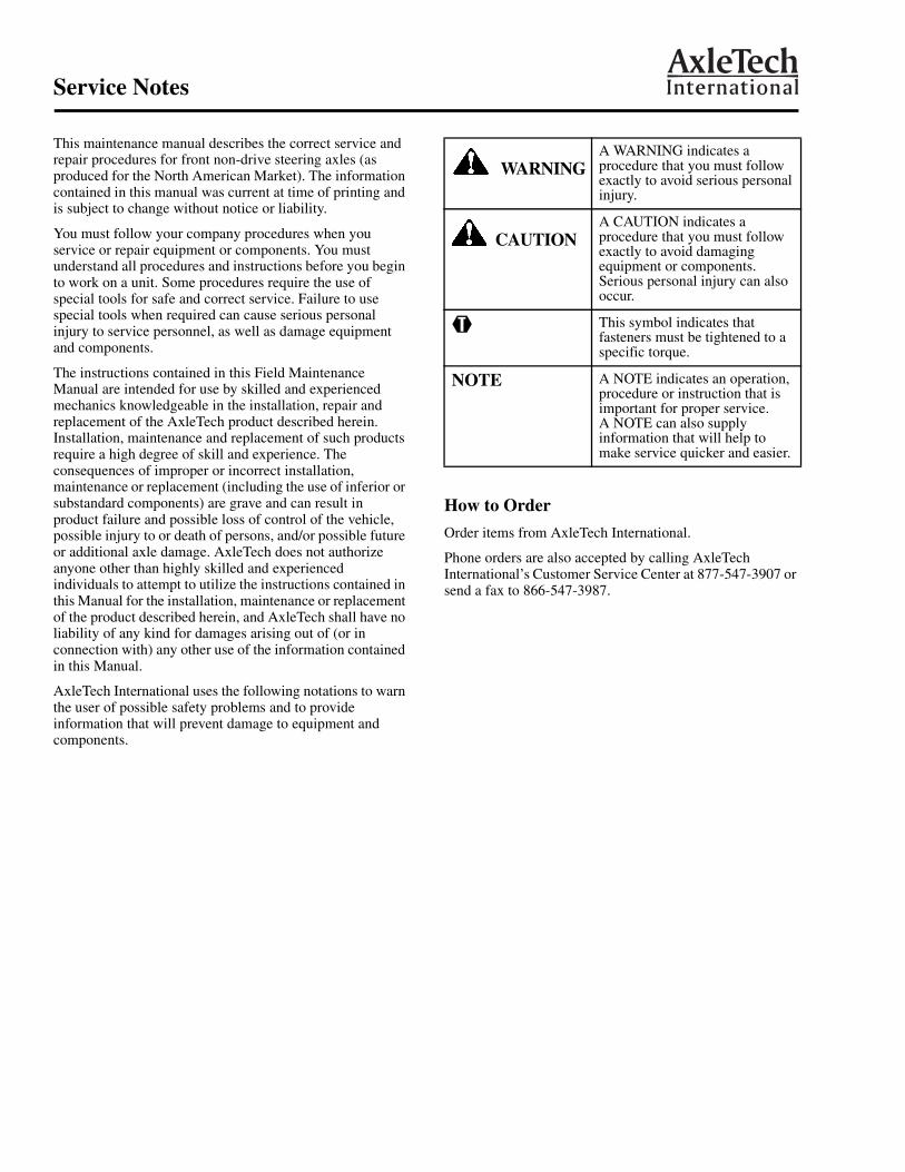
Service Notes
This maintenance manual describes the correct service and repair procedures for front non-drive steering axles (as produced for the North American Market). The information contained in this manual was current at time of printing and is subject to change without notice or liability.
You must follow your company procedures when you service or repair equipment or components. You must understand all procedures and instructions before you begin to work on a unit. Some procedures require the use of special tools for safe and correct service. Failure to use special tools when required can cause serious personal injury to service personnel, as well as damage equipment and components.
The instructions contained in this Field Maintenance Manual are intended for use by skilled and experienced mechanics knowledgeable in the installation, repair and replacement of the AxleTech product described herein. Installation, maintenance and replacement of such products require a high degree of skill and experience. The consequences of improper or incorrect installation, maintenance or replacement (including the use of inferior or substandard components) are grave and can result in product failure and possible loss of control of the vehicle, possible injury to or death of persons, and/or possible future or additional axle damage. AxleTech does not authorize anyone other than highly skilled and experienced individuals to attempt to utilize the instructions contained in this Manual for the installation, maintenance or replacement of the product described herein, and AxleTech shall have no liability of any kind for damages arising out of (or in connection with) any other use of the information contained in this Manual.
AxleTech International uses the following notations to warn the user of possible safety problems and to provide information that will prevent damage to equipment and components.
How to Order
Order items from AxleTech International.
Phone orders are also accepted by calling AxleTech International’s Customer Service Center at 877-547-3907 or send a fax to 866-547-3987.
WARNINGA WARNING indicates a procedure that you must follow exactly to avoid serious personal injury.
CAUTIONA CAUTION indicates a procedure that you must follow exactly to avoid damaging equipment or components. Serious personal injury can also occur.
@ This symbol indicates that fasteners must be tightened to a specific torque.
NOTE A NOTE indicates an operation, procedure or instruction that is important for proper service. A NOTE can also supply information that will help to make service quicker and easier.
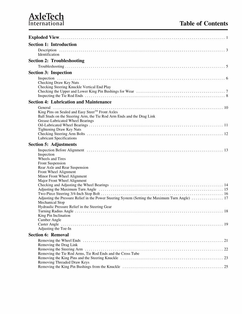
Table of Contents
Exploded View. . . . . . . . . . . . . . . . . . . . . . . . . . . . . . . . . . . . . . . . . . . . . . . . . . . . . . . . . . . . . . . . . . . . . . . . . . . . . . . . . . . . 1
Section 1: IntroductionDescription . . . . . . . . . . . . . . . . . . . . . . . . . . . . . . . . . . . . . . . . . . . . . . . . . . . . . . . . . . . . . . . . . . . . . . . . . . . . . . . . . . . . 3Identification
Section 2: Troubleshooting Troubleshooting . . . . . . . . . . . . . . . . . . . . . . . . . . . . . . . . . . . . . . . . . . . . . . . . . . . . . . . . . . . . . . . . . . . . . . . . . . . . . . . . . 5
Section 3: Inspection Inspection . . . . . . . . . . . . . . . . . . . . . . . . . . . . . . . . . . . . . . . . . . . . . . . . . . . . . . . . . . . . . . . . . . . . . . . . . . . . . . . . . . . . . 6Checking Draw Key NutsChecking Steering Knuckle Vertical End PlayChecking the Upper and Lower King Pin Bushings for Wear . . . . . . . . . . . . . . . . . . . . . . . . . . . . . . . . . . . . . . . . . . . . . 7Inspecting the Tie Rod Ends . . . . . . . . . . . . . . . . . . . . . . . . . . . . . . . . . . . . . . . . . . . . . . . . . . . . . . . . . . . . . . . . . . . . . . . 8
Section 4: Lubrication and Maintenance General . . . . . . . . . . . . . . . . . . . . . . . . . . . . . . . . . . . . . . . . . . . . . . . . . . . . . . . . . . . . . . . . . . . . . . . . . . . . . . . . . . . . . . 10King Pins on Sealed and Easy SteerTM Front AxlesBall Studs on the Steering Arm, the Tie Rod Arm Ends and the Drag LinkGrease-Lubricated Wheel BearingsOil-Lubricated Wheel Bearings . . . . . . . . . . . . . . . . . . . . . . . . . . . . . . . . . . . . . . . . . . . . . . . . . . . . . . . . . . . . . . . . . . . . 11Tightening Draw Key NutsChecking Steering Arm Bolts . . . . . . . . . . . . . . . . . . . . . . . . . . . . . . . . . . . . . . . . . . . . . . . . . . . . . . . . . . . . . . . . . . . . . 12Lubricant Specifications
Section 5: Adjustments Inspection Before Alignment . . . . . . . . . . . . . . . . . . . . . . . . . . . . . . . . . . . . . . . . . . . . . . . . . . . . . . . . . . . . . . . . . . . . . 13InspectionWheels and TiresFront SuspensionRear Axle and Rear SuspensionFront Wheel Alignment Minor Front Wheel AlignmentMajor Front Wheel AlignmentChecking and Adjusting the Wheel Bearings . . . . . . . . . . . . . . . . . . . . . . . . . . . . . . . . . . . . . . . . . . . . . . . . . . . . . . . . . 14Adjusting the Maximum Turn Angle . . . . . . . . . . . . . . . . . . . . . . . . . . . . . . . . . . . . . . . . . . . . . . . . . . . . . . . . . . . . . . . 15Two-Piece Steering 3/4-Inch Stop Bolt . . . . . . . . . . . . . . . . . . . . . . . . . . . . . . . . . . . . . . . . . . . . . . . . . . . . . . . . . . . . . . 16Adjusting the Pressure Relief in the Power Steering System (Setting the Maximum Turn Angle) . . . . . . . . . . . . . . . . 17Mechanical StopHydraulic Pressure Relief in the Steering GearTurning Radius Angle . . . . . . . . . . . . . . . . . . . . . . . . . . . . . . . . . . . . . . . . . . . . . . . . . . . . . . . . . . . . . . . . . . . . . . . . . . . 18King Pin Inclination Camber Angle Caster Angle . . . . . . . . . . . . . . . . . . . . . . . . . . . . . . . . . . . . . . . . . . . . . . . . . . . . . . . . . . . . . . . . . . . . . . . . . . . . . . . . . . 19Adjusting the Toe-In
Section 6: Removal Removing the Wheel Ends . . . . . . . . . . . . . . . . . . . . . . . . . . . . . . . . . . . . . . . . . . . . . . . . . . . . . . . . . . . . . . . . . . . . . . . 21Removing the Drag Link Removing the Steering Arm . . . . . . . . . . . . . . . . . . . . . . . . . . . . . . . . . . . . . . . . . . . . . . . . . . . . . . . . . . . . . . . . . . . . . . 22Removing the Tie Rod Arms, Tie Rod Ends and the Cross Tube Removing the King Pins and the Steering Knuckle . . . . . . . . . . . . . . . . . . . . . . . . . . . . . . . . . . . . . . . . . . . . . . . . . . . . 23Removing Threaded Draw KeysRemoving the King Pin Bushings from the Knuckle . . . . . . . . . . . . . . . . . . . . . . . . . . . . . . . . . . . . . . . . . . . . . . . . . . . 25

Table of Contents
Section 7: Preparing the Parts for Assembly Repairing of Parts . . . . . . . . . . . . . . . . . . . . . . . . . . . . . . . . . . . . . . . . . . . . . . . . . . . . . . . . . . . . . . . . . . . . . . . . . . . . . . 26Cleaning the Ground or Polished Parts Cleaning the Rough Parts Drying the Cleaned Parts Preventing Corrosion on Cleaned Parts Installing New Fasteners with Pre-applied Adhesive Patches Installing Original or Used Fasteners Using Loctite® 680 or Equivalent . . . . . . . . . . . . . . . . . . . . . . . . . . . . . . . . . . . . 27Inspecting the Parts Inspecting the Wheel Bearings . . . . . . . . . . . . . . . . . . . . . . . . . . . . . . . . . . . . . . . . . . . . . . . . . . . . . . . . . . . . . . . . . . . . 29
Section 8: InstallationInstalling Easy SteerTM King Pin Bushings in the Knuckle . . . . . . . . . . . . . . . . . . . . . . . . . . . . . . . . . . . . . . . . . . . . . . . 30Without a PressWith a Press Reaming the Easy SteerTM Bushings . . . . . . . . . . . . . . . . . . . . . . . . . . . . . . . . . . . . . . . . . . . . . . . . . . . . . . . . . . . . . . . . 31Installing the Inner Knuckle Bore King Pin Seals . . . . . . . . . . . . . . . . . . . . . . . . . . . . . . . . . . . . . . . . . . . . . . . . . . . . . . 33Installing the Knuckle to Axle Beam . . . . . . . . . . . . . . . . . . . . . . . . . . . . . . . . . . . . . . . . . . . . . . . . . . . . . . . . . . . . . . . . 34Installing the Tie Rod Arms, Tie Rod Ends and the Cross Tube Assembly. . . . . . . . . . . . . . . . . . . . . . . . . . . . . . . . . . . 37Installing the Steering Arm . . . . . . . . . . . . . . . . . . . . . . . . . . . . . . . . . . . . . . . . . . . . . . . . . . . . . . . . . . . . . . . . . . . . . . . 39Installing the Drag Link Installing the Brake Components and Wheel Ends . . . . . . . . . . . . . . . . . . . . . . . . . . . . . . . . . . . . . . . . . . . . . . . . . . . . . 40
Section 9: Torque Specifications Front Axle Torque Illustration . . . . . . . . . . . . . . . . . . . . . . . . . . . . . . . . . . . . . . . . . . . . . . . . . . . . . . . . . . . . . . . . . . . . . 41
Section 10: Special Tools . . . . . . . . . . . . . . . . . . . . . . . . . . . . . . . . . . . . . . . . . . . . . . . . . . . . . . . . . . . . . . . . . . . . . . . 42
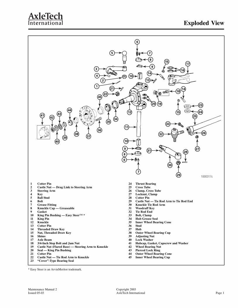
Exploded View
Maintenance Manual 2 Copyright 2003Issued 05-03 AxleTech International Page 1
* Easy Steer is an ArvinMeritor trademark.
1 Cotter Pin2 Castle Nut — Drag Link to Steering Arm3 Steering Arm4 Key5 Ball Stud6 Bolt7 Grease Fitting8 Knuckle Cap — Greaseable9 Gasket10 King Pin Bushing — Easy Steer™ *11 King Pin12 Knuckle13 Cotter Pin14 Threaded Draw Key15 Nut, Threaded Draw Key16 Shims17 Axle Beam18 3/4-Inch Stop Bolt and Jam Nut19 Castle Nut (Flared Base) — Steering Arm to Knuckle20 Seal — King Pin Bushing21 Cotter Pin22 Castle Nut — Tie Rod Arm to Knuckle23 “Cover”-Type Bearing Seal
24 Thrust Bearing25 Cross Tube26 Clamp, Cross Tube27 Locknut, Clamp28 Cotter Pin29 Castle Nut — Tie Rod Arm to Tie Rod End30 Knuckle Tie Rod Arm31 Woodruff Key32 Tie Rod End33 Bolt, Clamp34 Hub Grease Seal35 Inner Wheel Bearing Cone36 Stud37 Hub38 Outer Wheel Bearing Cup39 Adjusting Nut40 Lock Washer41 Hubcap, Gasket, Capscrew and Washer42 Wheel Bearing Nut43 Pierced Lock Ring44 Outer Wheel Bearing Cone45 Inner Wheel Bearing Cup
1000317c
7
12
30
29
15
27
19
37
36
3534
40
39
38 26
18
16
20
9
7
6
9
8
10
11
31
32
33
14
13
10
5
4
3
22
21
28
25
17
14
15
6
1
2
41
45
42
43
44
23
24
8

Notes
Copyright 2003 Maintenance Manual 2Page 2 AxleTech International Issued 05-03
Section 1Introduction
Maintenance Manual 2 Copyright 2003Issued 05-03 AxleTech International Page 3
Section 1Introduction
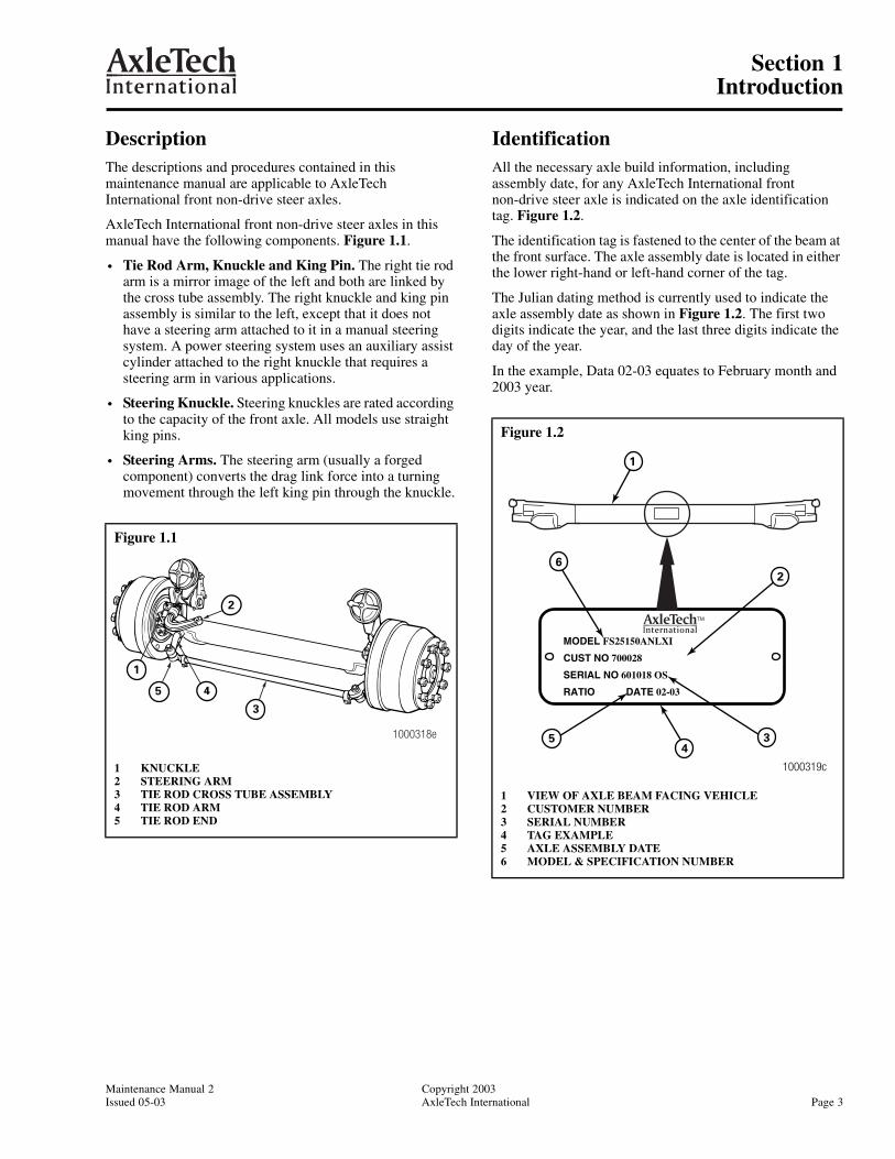
DescriptionThe descriptions and procedures contained in this maintenance manual are applicable to AxleTech International front non-drive steer axles.
AxleTech International front non-drive steer axles in this manual have the following components. Figure 1.1.
• Tie Rod Arm, Knuckle and King Pin. The right tie rod arm is a mirror image of the left and both are linked by the cross tube assembly. The right knuckle and king pin assembly is similar to the left, except that it does not have a steering arm attached to it in a manual steering system. A power steering system uses an auxiliary assist cylinder attached to the right knuckle that requires a steering arm in various applications.
• Steering Knuckle. Steering knuckles are rated according to the capacity of the front axle. All models use straight king pins.
• Steering Arms. The steering arm (usually a forged component) converts the drag link force into a turning movement through the left king pin through the knuckle.
IdentificationAll the necessary axle build information, including assembly date, for any AxleTech International front non-drive steer axle is indicated on the axle identification tag. Figure 1.2.
The identification tag is fastened to the center of the beam at the front surface. The axle assembly date is located in either the lower right-hand or left-hand corner of the tag.
The Julian dating method is currently used to indicate the axle assembly date as shown in Figure 1.2. The first two digits indicate the year, and the last three digits indicate the day of the year.
In the example, Data 02-03 equates to February month and 2003 year.
Figure 1.1
1 KNUCKLE2 STEERING ARM3 TIE ROD CROSS TUBE ASSEMBLY4 TIE ROD ARM5 TIE ROD END
4
2
3
5
1
1000318e
Figure 1.2
1 VIEW OF AXLE BEAM FACING VEHICLE2 CUSTOMER NUMBER3 SERIAL NUMBER4 TAG EXAMPLE5 AXLE ASSEMBLY DATE6 MODEL & SPECIFICATION NUMBER
MODEL FS25150ANLXI
CUST NO 700028
SERIAL NO 601018 OS
RATIO DATE 02-03
1000319c
5 3
2
4
1
6

Section 1Introduction
Copyright 2003 Maintenance Manual 2Page 4 AxleTech International Issued 05-03
To identify the model number, see the identification plate on the front of the beam. Use the complete model number to order parts. Figure 1.3.
Refer to Figure 1.3 for an explanation of the model number.
Figure 1.3
1 Easy Steer is an ArvinMeritor trademark.2 Q Plus Cam Brake is an ArvinMeritor trademark.
EXAMPLE: FS25150ANLX2
F = Front
S = Non-Drive Steer Axle
GAWR PoundsREF: Target Market
SPINDLE TO BEAMCENTERLINE DROP0 = 1.50 in. (38 mm)
KPI0 = 79.6 in. (2,022 mm)5 = 72.0 in. (1,829 mm)7 = 68.9 in. (1,750 mm)
BEAM, KINGPIN, BUSHING VARIATION1 = Straight Kingpins — Easy SteerTM 1 Bushing
MAJOR DESIGN VARIATIONA = Conventional Knuckle
MANUFACTURING LOCATIONN = N.A.
BRAKE TYPE:LX — Q PlusTM 2 Cam Brake
Axle Spec. Number
F S XX 1 5 0 X N LX X
Front Non-Drive Steer Axle — Model Nomenclature

Section 2Troubleshooting
Maintenance Manual 2 Copyright 2003Issued 05-03 AxleTech International Page 5
Section 2Troubleshooting
TroubleshootingThe following chart is for troubleshooting axle conditions.
Condition Cause Correction
Tires wear out quickly or have uneven tire tread wear.
1. Tires have incorrect air pressure.
2. Tires out-of-balance.
3. Incorrect tandem axle alignment.
4. Incorrect toe-in setting.
5. Incorrect steering arm geometry.
6. Excessive wheel end play exists.
1. Place specified air pressure in tires.
2. Balance or replace tires.
3. Align tandem axles.
4. Adjust toe-in specified setting.
5. Service steering system as necessary.
6. Readjust wheel bearings.
Vehicle is hard to steer. 1. Power steering system pressure low.
2. Steering gear linkage not assembled correctly.
3. Steering linkage needs lubrication.
4. King pins binding.
5. Incorrect steering arm geometry.
6. Caster out-of-adjustment.
7. Tie rod ends hard to move.
8. Worn thrust bearing.
1. Repair power steering system.
2. Assemble steering gear correctly.
3. Lubricate steering linkage.
4. Replace king pins.
5. Service steering system as necessary.
6. Adjust caster as necessary.
7. Replace tie rod ends.
8. Replace thrust bearing.
Tie rod ends are worn and require replacement.
1. Tie rod ends require lubrication.
2. Severe operating conditions.
3. Damaged boot on tie rod end.
1. Lubricate ends of cross tube. Make sure lubrication schedule is followed.
2. Operate vehicle correctly.
3. Replace boot.
Bent or broken cross tube, tie rod end ball stud, steering arm or tie rod end. (Component requires replacement.)
1. Too much pressure in the power steering system, pressure exceeds OEM specification.
2. Power steering system cut-off pressure, out of adjustment.
3. Vehicle operated under severe conditions.
4. Add-on type of power steering system not installed correctly.
1. Adjust power steering system to specified pressure.
2. Adjust power steering system to specified pressure.
3. Make sure vehicle is operated correctly.
4. Correctly install add-on power steering system.
Worn or broken steering ball stud. 1. Drag link fasteners tightened higher than OEM specified.
2. Lack of lubrication or incorrect lubricant.
3. Power steering stops out-of-adjustment.
1. Tighten drag link fasteners to specified torque.
2. Lubricate linkage with specified lubricant.
3. Adjust stops to specified dimension.
Worn king pins and king pin bushings.
1. Worn or missing seals and gaskets.
2. Incorrect lubricant.
3. Axle not lubricated at scheduled frequency.
4. Incorrect lubrication procedures.
5. Lubrication schedule does not match operating conditions.
1. Replace seals and gaskets.
2. Lubricate axle with specified lubricant.
3. Lubricate axle at scheduled frequency.
4. Use correct lubrication procedures.
5. Change lubrication schedule to match operating conditions.
Vibration or shimmy of front axle during operation.
1. Caster out-of-adjustment.
2. Wheels and/or tires out-of-balance.
3. Worn shock absorbers.
1. Adjust caster.
2. Balance or replace wheels and/or tires.
3. Replace shock absorbers.
Section 3Inspection
Copyright 2003 Maintenance Manual 2Page 6 AxleTech International Issued 05-03
Section 3Inspection
Inspection
WARNINGTo prevent serious eye injury, always wear safe eye protection when you perform vehicle maintenance or service.
CAUTIONThe repair or reconditioning of front axle components is not allowed. AxleTech International recommends replacing damaged or out-of-specification components. The tubular axle beam can only be welded as defined by written agreement with AxleTech International’s Engineering department. All other major components are heat treated and tempered. Those components cannot be bent, welded, heated or repaired in any way without reducing the strength or life of the component and voiding the warranty and may cause a vehicle accident which can result in serious personal injury.
Perform the following during an inspection.
• Fasteners. Make sure all fasteners are tightened to the specified torque. Use a torque wrench to check the torque in a tightening direction. As soon as the fastener starts to move, record the torque. Correct if necessary. Replace any worn or damaged fasteners.
• Wear and Damage. Inspect the parts of the axle for wear and damage. Look for bent or cracked parts. Replace all worn or damaged parts.
• Pivot Points. Make sure looseness does not exist at the pivot points. Make sure the pivot points are lubricated.
• Operation. Make sure all the parts move freely through the complete turning radius.
• Tire Wear. Inspect the tires for wear patterns that indicate suspension damage or misalignment.
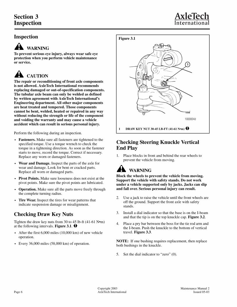
Checking Draw Key NutsTighten the draw key nuts from 30 to 45 lb-ft (41-61 N•m) at the following intervals. Figure 3.1. @
• After the first 6,000 miles (10,000 km) of new vehicle operation.
• Every 36,000 miles (58,000 km) of operation.
Checking Steering Knuckle Vertical End Play 1. Place blocks in front and behind the rear wheels to
prevent the vehicle from moving.
WARNINGBlock the wheels to prevent the vehicle from moving. Support the vehicle with safety stands. Do not work under a vehicle supported only by jacks. Jacks can slip and fall over. Serious personal injury can result.
2. Use a jack to raise the vehicle until the front wheels are off the ground. Support the front axle with safety stands.
3. Install a dial indicator so that the base is on the I-beam and that the tip is on the top knuckle cap. Figure 3.2.
4. Place a pry bar between the boss for the tie rod arm and the I-beam. Push the knuckle to the bottom of vertical travel. Figure 3.3.
NOTE: If one bushing requires replacement, then replace both bushings in the knuckle.
5. Set the dial indicator to “zero” (0).
Figure 3.1
1 DRAW KEY NUT 30-45 LB-FT (41-61 N•m) @
1000004d
1
Section 3Inspection
Maintenance Manual 2 Copyright 2003Issued 05-03 AxleTech International Page 7
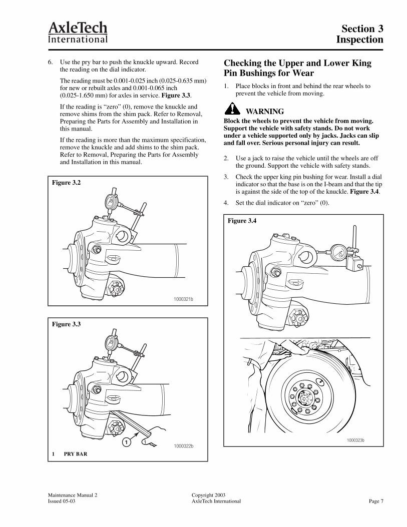
6. Use the pry bar to push the knuckle upward. Recordthe reading on the dial indicator.
The reading must be 0.001-0.025 inch (0.025-0.635 mm) for new or rebuilt axles and 0.001-0.065 inch(0.025-1.650 mm) for axles in service. Figure 3.3.
If the reading is “zero” (0), remove the knuckle and remove shims from the shim pack. Refer to Removal, Preparing the Parts for Assembly and Installation in this manual.
If the reading is more than the maximum specification, remove the knuckle and add shims to the shim pack. Refer to Removal, Preparing the Parts for Assembly and Installation in this manual.
Checking the Upper and Lower King Pin Bushings for Wear1. Place blocks in front and behind the rear wheels to
prevent the vehicle from moving.
WARNINGBlock the wheels to prevent the vehicle from moving. Support the vehicle with safety stands. Do not work under a vehicle supported only by jacks. Jacks can slip and fall over. Serious personal injury can result.
2. Use a jack to raise the vehicle until the wheels are off the ground. Support the vehicle with safety stands.
3. Check the upper king pin bushing for wear. Install a dial indicator so that the base is on the I-beam and that the tip is against the side of the top of the knuckle. Figure 3.4.
4. Set the dial indicator on “zero” (0).
Figure 3.2
Figure 3.3
1 PRY BAR
1000321b
1000322b1
Figure 3.4
1000323b
Section 3Inspection
Copyright 2003 Maintenance Manual 2Page 8 AxleTech International Issued 05-03
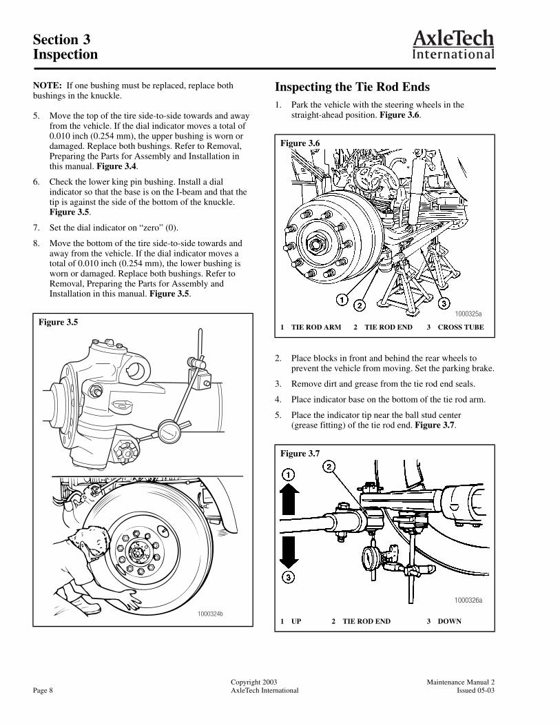
NOTE: If one bushing must be replaced, replace both bushings in the knuckle.
5. Move the top of the tire side-to-side towards and away from the vehicle. If the dial indicator moves a total of 0.010 inch (0.254 mm), the upper bushing is worn or damaged. Replace both bushings. Refer to Removal, Preparing the Parts for Assembly and Installation in this manual. Figure 3.4.
6. Check the lower king pin bushing. Install a dial indicator so that the base is on the I-beam and that the tip is against the side of the bottom of the knuckle. Figure 3.5.
7. Set the dial indicator on “zero” (0).
8. Move the bottom of the tire side-to-side towards and away from the vehicle. If the dial indicator moves a total of 0.010 inch (0.254 mm), the lower bushing is worn or damaged. Replace both bushings. Refer to Removal, Preparing the Parts for Assembly and Installation in this manual. Figure 3.5.
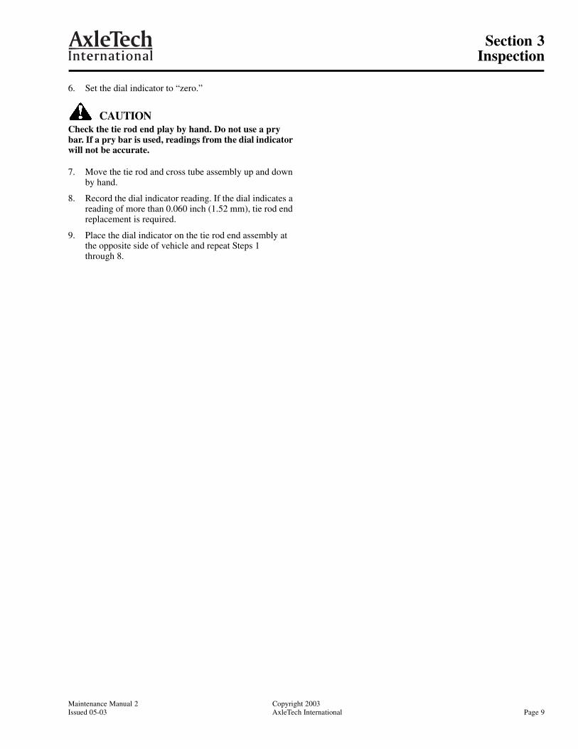
Inspecting the Tie Rod Ends1. Park the vehicle with the steering wheels in the
straight-ahead position. Figure 3.6.
2. Place blocks in front and behind the rear wheels to prevent the vehicle from moving. Set the parking brake.
3. Remove dirt and grease from the tie rod end seals.
4. Place indicator base on the bottom of the tie rod arm.
5. Place the indicator tip near the ball stud center(grease fitting) of the tie rod end. Figure 3.7.
Figure 3.5
1000324b
Figure 3.6
1 TIE ROD ARM 2 TIE ROD END 3 CROSS TUBE
Figure 3.7
1 UP 2 TIE ROD END 3 DOWN
1000325a
1000326a
Section 3Inspection
Maintenance Manual 2 Copyright 2003Issued 05-03 AxleTech International Page 9
6. Set the dial indicator to “zero.”
CAUTIONCheck the tie rod end play by hand. Do not use a pry bar. If a pry bar is used, readings from the dial indicator will not be accurate.
7. Move the tie rod and cross tube assembly up and down by hand.
8. Record the dial indicator reading. If the dial indicates a reading of more than 0.060 inch (1.52 mm), tie rod end replacement is required.
9. Place the dial indicator on the tie rod end assembly at the opposite side of vehicle and repeat Steps 1through 8.
Section 4Lubrication and Maintenance
Copyright 2003 Maintenance Manual 2Page 10 AxleTech International Issued 05-03
Section 4Lubrication and Maintenance
General
WARNINGTo prevent serious eye injury, always wear safe eye protection when you perform vehicle maintenance or service.
Lubricate the king pins, the ball studs on the tie rod arm ends, the ball stud on the steering arm and the grease-lubricated wheel bearings with the approved lubricant. Refer to Table A.
Lubricate the oil-lubricated wheel bearings with the oil specified in Table B.
King Pins on Sealed and Easy Steer™ Front Axles
WARNINGBlock the wheels to prevent the vehicle from moving. Support the vehicle with safety stands. Do not work under a vehicle supported only by jacks. Jacks can slip and fall over. Serious personal injury can result.
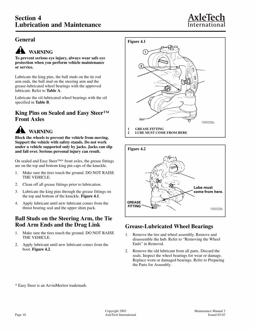
On sealed and Easy Steer™* front axles, the grease fittings are on the top and bottom king pin caps of the knuckle.
1. Make sure the tires touch the ground. DO NOT RAISE THE VEHICLE.
2. Clean off all grease fittings prior to lubrication.
3. Lubricate the king pins through the grease fittings on the top and bottom of the knuckle. Figure 4.1.
4. Apply lubricant until new lubricant comes from the thrust bearing seal and the upper shim pack.
Ball Studs on the Steering Arm, the Tie Rod Arm Ends and the Drag Link1. Make sure the tires touch the ground. DO NOT RAISE
THE VEHICLE.
2. Apply lubricant until new lubricant comes from the boot. Figure 4.2.
Grease-Lubricated Wheel Bearings1. Remove the tire and wheel assembly. Remove and
disassemble the hub. Refer to “Removing the Wheel Ends” in Removal.
2. Remove the old lubricant from all parts. Discard the seals. Inspect the wheel bearings for wear or damage. Replace worn or damaged bearings. Refer to Preparing the Parts for Assembly.
Figure 4.1
1 GREASE FITTING2 LUBE MUST COME FROM HERE
Figure 4.2
1000328a
1000329c
GREASEFITTING
Lube mustcome from here.
* Easy Steer is an ArvinMeritor trademark.
Section 4Lubrication and Maintenance
Maintenance Manual 2 Copyright 2003Issued 05-03 AxleTech International Page 11
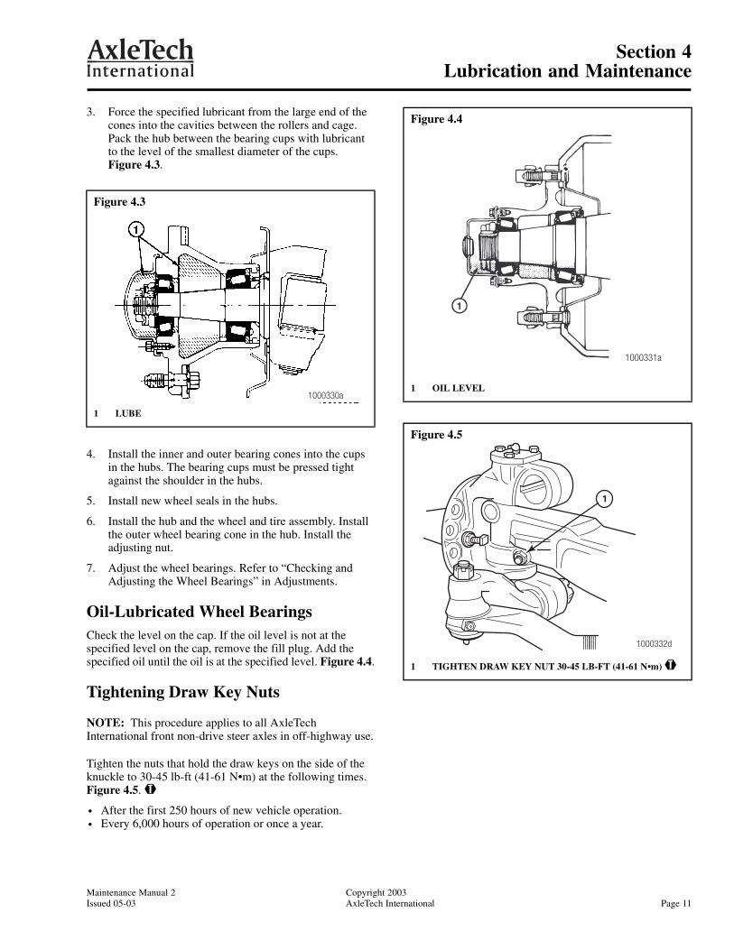
3. Force the specified lubricant from the large end of the cones into the cavities between the rollers and cage. Pack the hub between the bearing cups with lubricant to the level of the smallest diameter of the cups. Figure 4.3.
4. Install the inner and outer bearing cones into the cups in the hubs. The bearing cups must be pressed tight against the shoulder in the hubs.
5. Install new wheel seals in the hubs.
6. Install the hub and the wheel and tire assembly. Install the outer wheel bearing cone in the hub. Install the adjusting nut.
7. Adjust the wheel bearings. Refer to “Checking and Adjusting the Wheel Bearings” in Adjustments.
Oil-Lubricated Wheel BearingsCheck the level on the cap. If the oil level is not at the specified level on the cap, remove the fill plug. Add the specified oil until the oil is at the specified level. Figure 4.4.
Tightening Draw Key Nuts
NOTE: This procedure applies to all AxleTech International front non-drive steer axles in off-highway use.
Tighten the nuts that hold the draw keys on the side of the knuckle to 30-45 lb-ft (41-61 N•m) at the following times. Figure 4.5. @
• After the first 250 hours of new vehicle operation.• Every 6,000 hours of operation or once a year.
Figure 4.3
1 LUBE
1000330a
Figure 4.4
1 OIL LEVEL
Figure 4.5
1 TIGHTEN DRAW KEY NUT 30-45 LB-FT (41-61 N•m) @
1000331a
1
1000332d
Section 4Lubrication and Maintenance
Copyright 2003 Maintenance Manual 2Page 12 AxleTech International Issued 05-03
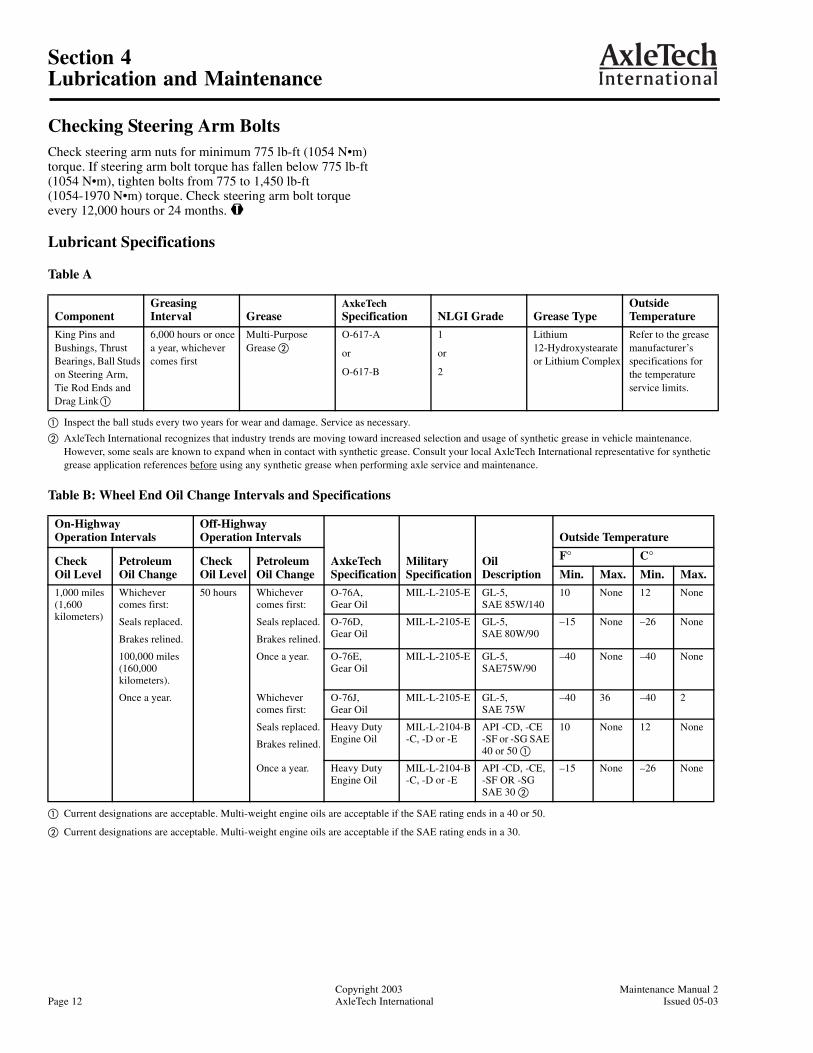
Checking Steering Arm BoltsCheck steering arm nuts for minimum 775 lb-ft (1054 N•m) torque. If steering arm bolt torque has fallen below 775 lb-ft(1054 N•m), tighten bolts from 775 to 1,450 lb-ft(1054-1970 N•m) torque. Check steering arm bolt torqueevery 12,000 hours or 24 months. @
Lubricant Specifications
Table A
Table B: Wheel End Oil Change Intervals and Specifications
ComponentGreasing Interval Grease
AxkeTech Specification NLGI Grade Grease Type
Outside Temperature
King Pins and Bushings, Thrust Bearings, Ball Studs on Steering Arm, Tie Rod Ends and Drag Linka
6,000 hours or once a year, whichever comes first
Multi-Purpose Grease b
O-617-A
or
O-617-B
1
or
2
Lithium 12-Hydroxystearate or Lithium Complex
Refer to the grease manufacturer’s specifications for the temperature service limits.
a Inspect the ball studs every two years for wear and damage. Service as necessary.
b AxleTech International recognizes that industry trends are moving toward increased selection and usage of synthetic grease in vehicle maintenance. However, some seals are known to expand when in contact with synthetic grease. Consult your local AxleTech International representative for synthetic grease application references before using any synthetic grease when performing axle service and maintenance.
On-Highway Operation Intervals
Off-HighwayOperation Intervals
AxkeTech Specification
Military Specification
Oil Description
Outside Temperature
CheckOil Level
Petroleum Oil Change
Check Oil Level
Petroleum Oil Change
F° C°Min. Max. Min. Max.
1,000 miles (1,600 kilometers)
Whichever comes first:
50 hours Whichever comes first:
O-76A,Gear Oil
MIL-L-2105-E GL-5, SAE 85W/140
10 None 12 None
Seals replaced.
Brakes relined.
Seals replaced.
Brakes relined.
O-76D, Gear Oil
MIL-L-2105-E GL-5, SAE 80W/90
–15 None –26 None
100,000 miles (160,000 kilometers).
Once a year. O-76E,Gear Oil
MIL-L-2105-E GL-5, SAE75W/90
–40 None –40 None
Once a year. Whichever comes first:
O-76J,Gear Oil
MIL-L-2105-E GL-5, SAE 75W
–40 36 –40 2
Seals replaced.
Brakes relined.
Heavy Duty Engine Oil
MIL-L-2104-B -C, -D or -E
API -CD, -CE -SF or -SG SAE 40 or 50 a
10 None 12 None
Once a year. Heavy Duty Engine Oil
MIL-L-2104-B -C, -D or -E
API -CD, -CE, -SF OR -SG SAE 30 b
–15 None –26 None
a Current designations are acceptable. Multi-weight engine oils are acceptable if the SAE rating ends in a 40 or 50.
b Current designations are acceptable. Multi-weight engine oils are acceptable if the SAE rating ends in a 30.
Section 5Adjustments
Maintenance Manual 2 Copyright 2003Issued 05-03 AxleTech International Page 13
Section 5Adjustments
Inspection Before AlignmentCheck the following before doing a front wheel alignment.
Inspection
Refer to Inspection in this manual.
Wheels and Tires
Check the following items:
• Make sure the tires are inflated to the specified pressure.
• Make sure the front tires are the same size and type.
• Make sure the lug nuts are tightened to the specified torque.
• Make sure the wheels are balanced.
• Check for bent or damaged wheels.
Front Suspension
Check the following items:
• Make sure all fasteners are tightened to the specified torque.
• Inspect the leaf springs for wear and damage.
• Inspect the shock absorbers for wear and damage.
Rear Axle and Rear Suspension
Front tire wear can be caused by the rear axle. If the outer edge of one front tire is worn and the inner edge of the other front tire is worn, check the following:
• Make sure all fasteners are tightened to the specified torque.
• Make sure the leaf springs are not worn or damaged.
• Make sure the bushings in the leaf springs are not worn or damaged.
• Make sure the torque rods (if used) are correctly adjusted.
• Make sure the frame is not bent.
• Make sure the rear axle (especially a tandem axle) is correctly aligned. Refer to the procedure of the manufacturer of the vehicle or the suspension.
• Refer to any additional rear axle and suspension recommendations and specifications from the vehicle manufacturer.
Front Wheel AlignmentCheck the front wheel alignment when the following occur:
• Every 12,000 hours or 24 months (normal maintenance).
• When the vehicle does not steer correctly.
• To correct a tire wear condition.
There are two types of front wheel alignment:
• Minor alignment.
• Major alignment.
Minor Front Wheel Alignment
Perform a minor front wheel alignment for all normal maintenance conditions.
Perform the minor front wheel alignment in the following sequence:
1. Inspect all the systems that affect the wheel alignment. Refer to “Inspection Before Alignment” in this section.
2. Check and adjust the wheel bearings.
3. Check and adjust the toe-in.
Major Front Wheel Alignment
Perform a major front wheel alignment to correct steering and tire wear conditions.
Perform the major front wheel alignment in the following sequence:
1. Inspect all the systems that affect the wheel alignment. Refer to “Inspection Before Alignment” in this section.
2. Check and adjust the wheel bearings.
3. Check and adjust the maximum turn angle.
4. If the vehicle has power steering, check and adjust the pressure relief in the power steering system. Refer to the procedure “Adjusting the Pressure Relief in the Power Steering System (Setting the Maximum Turn Angle)” in this section.
5. Check and adjust the turning radius angle (toe-out on turns or Ackerman angle).
6. Check the king pin (or steering axis) inclination.
7. Check the camber angle.
Section 5Adjustments
Copyright 2003 Maintenance Manual 2Page 14 AxleTech International Issued 05-03
CAUTIONAxle camber is not adjustable. Do not change the axle camber angle or bend the axle beam. Bending the axle beam to change the camber angle can damage the axle and reduce axle strength, and will void AxleTech International’s warranty. A bent axle beam can also cause a vehicle accident and serious personal injury.
8. Check and adjust the caster angle.
9. Check and adjust the toe-in.
Checking and Adjusting the Wheel Bearings
WARNINGBlock the wheels to prevent the vehicle from moving. Support the vehicle with safety stands. Do not work under a vehicle supported only by jacks. Jacks can slip and fall over. Serious personal injury can result.
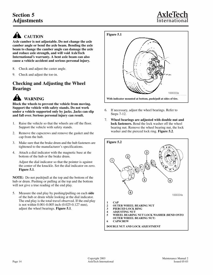
1. Raise the vehicle so that the wheels are off the floor. Support the vehicle with safety stands.
2. Remove the capscrews and remove the gasket and the cap from the hub.
3. Make sure that the brake drum and the hub fasteners are tightened to the manufacturer’s specifications.
4. Attach a dial indicator with the magnetic base at the bottom of the hub or the brake drum.
Adjust the dial indicator so that the pointer is against the center of the knuckle. Set the dial indicator on zero. Figure 5.1.
NOTE: Do not push/pull at the top and the bottom of the hub or drum. Pushing or pulling at the top and the bottom will not give a true reading of the end play.
5. Measure the end play by pushing/pulling on each side of the hub or drum while looking at the dial indicator. The end play is the total travel observed. If the end play is not within 0.001-0.005 inch (0.025-0.127 mm), adjust the wheel bearings. Figure 5.1.
6. If necessary, adjust the wheel bearings. Refer to Steps 7-12.
7. Wheel bearings are adjusted with double nut and lock fasteners. Bend the lock washer off the wheel bearing nut. Remove the wheel bearing nut, the lock washer and the pierced lock ring. Figure 5.2.
Figure 5.1
With indicator mounted at bottom, push/pull at sides of tire.
Figure 5.2
1 CAP2 OUTER WHEEL BEARING NUT3 PIERCED LOCK RING4 ADJUSTING NUT5 WHEEL BEARING NUT LOCK WASHER (BEND ONTO
OUTER WHEEL BEARING NUT)6 CAPSCREW
DOUBLE NUT AND LOCK ADJUSTMENT
1000333a
1000334a
Section 5Adjustments
Maintenance Manual 2 Copyright 2003Issued 05-03 AxleTech International Page 15
NOTE: When removing or installing the adjusting nuts, use the correct wrench socket to avoid damaging the adjusting nuts.
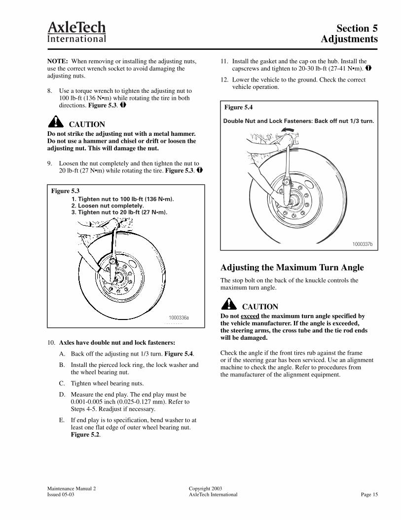
8. Use a torque wrench to tighten the adjusting nut to 100 lb-ft (136 N•m) while rotating the tire in both directions. Figure 5.3. @
CAUTIONDo not strike the adjusting nut with a metal hammer.Do not use a hammer and chisel or drift or loosen the adjusting nut. This will damage the nut.
9. Loosen the nut completely and then tighten the nut to 20 lb-ft (27 N•m) while rotating the tire. Figure 5.3. @
10. Axles have double nut and lock fasteners:
A. Back off the adjusting nut 1/3 turn. Figure 5.4.
B. Install the pierced lock ring, the lock washer and the wheel bearing nut.
C. Tighten wheel bearing nuts.
D. Measure the end play. The end play must be 0.001-0.005 inch (0.025-0.127 mm). Refer toSteps 4-5. Readjust if necessary.
E. If end play is to specification, bend washer to at least one flat edge of outer wheel bearing nut. Figure 5.2.
11. Install the gasket and the cap on the hub. Install the capscrews and tighten to 20-30 lb-ft (27-41 N•m). @
12. Lower the vehicle to the ground. Check the correct vehicle operation.
Adjusting the Maximum Turn AngleThe stop bolt on the back of the knuckle controls the maximum turn angle.
CAUTIONDo not exceed the maximum turn angle specified by the vehicle manufacturer. If the angle is exceeded, the steering arms, the cross tube and the tie rod endswill be damaged.
Check the angle if the front tires rub against the frame or if the steering gear has been serviced. Use an alignment machine to check the angle. Refer to procedures fromthe manufacturer of the alignment equipment.
Figure 5.3
1000336a
1. Tighten nut to 100 lb-ft (136 N•m).2. Loosen nut completely.3. Tighten nut to 20 lb-ft (27 N•m).
Figure 5.4
1000337b
Double Nut and Lock Fasteners: Back off nut 1/3 turn.

Section 5Adjustments
Copyright 2003 Maintenance Manual 2Page 16 AxleTech International Issued 05-03
For power steering systems, the stop bolt should NOT touch the beam. The stop bolt should always have a minimum clearance of 1/8 inch (3 mm), as shown in Figure 5.5, when the knuckle is in the full turn position.
For manual steering systems, AxleTech International recommends a stop bolt clearance of 1/8 inch (3 mm). Stop bolt contact is acceptable if no other stops are used for the maximum turn angle of the steering knuckle.
CAUTIONIf the stop bolt is missing, bent or broken, the system requires adjustment. Refer to “Mechanical Stop” in this section.
NOTE: If the steering system is out of adjustment, inspect the steering arm for damage. Use a magnetic particle or liquid dye penetrant inspection procedure to inspect the steering arm. Pay particular attention to the bend, the taper and the area near the ball stud. Refer to the manual from the vehicle manufacturer for additional inspection procedures.
CAUTIONIn power steering systems, the hydraulic pressure should relieve or “drop off” at the end of the steering stroke (with 1/8-inch or 3 mm minimum clearance at the stop bolt). If the pressure does not relieve, the components of the front axle will be damaged.
Two-Piece Steering 3/4-Inch Stop Bolt
1. Put a 1/8-inch (3 mm) spacer between the stop bolt and the boss on the axle beam.
2. Turn the steering wheel until the boss on the axle beam touches the spacer in front of the stop bolt. Measure the turn angle. Figure 5.6.
3. If the maximum turn angle does not meet vehicle manufacturer’s specifications, correct the maximum angle. In a power steering system, adjust the pressure relief. In a manual steering system, follow guidelines and specifications from the vehicle manufacturer.
4. When the maximum turn angle is correct:
A. Loosen stop bolt jam nut. Figure 5.6.
B. Insert 1/8-inch spacer and adjust the stop bolt.
C. Tighten the jam nut from 65-85 lb-ft (68-101 N•m). @
Figure 5.5
1 STOP BOLT2 1/8-INCH SPACER3 1/8-INCH (3 MM) CLEARANCE BETWEEN STOP BOLT
AND BOSS4 JAM NUT5 MAXIMUM TURN ANGLE
REFERENCES TO KNUCKLE FOR STOP BOLT ADJUSTMENT
1
23
4
5
1000338c
Figure 5.6
1 MAXIMUM TURN ANGLE2 AXLE BEAM BOSS3 1/8-INCH SPACER4 3/4-INCH STOP BOLT5 JAM NUT6 2-PIECE STOP BOLT ASSEMBLY
TWO-PIECE 3/4-INCH STEERING STOP BOLT
1000339a

Section 5Adjustments
Maintenance Manual 2 Copyright 2003Issued 05-03 AxleTech International Page 17
Adjusting the Pressure Relief in the Power Steering System (Setting the Maximum Turn Angle)The pressure relief in the power steering system stops or reduces forces applied to the axle when the wheel is moved in the full turn position.
Check the pressure relief if the steering arm is damaged or the power steering gear is serviced.
Two types of systems are used to adjust the pressure relief.
• Mechanical Stop on the Pitman Arm or in the Assist Cylinder.
• Hydraulic Pressure Relief in the Power Steering Gear.
CAUTIONAxleTech International does not recommend a power steering system that does not have mechanical stops or pressure relief before the maximum turn angle is obtained. The stops or the pressure relief are used to prevent damage to the axle.
Mechanical Stop
Use the mechanical stop in the steering system to adjust the pressure relief. Do not use the stop bolt on the knuckle alone to adjust the poppet valve pressure relief.
NOTE: Refer to the specified procedures from the manufacturer of the vehicle.
CAUTIONUse a pressure gauge to make sure that the pressure drops from the maximum system delivery pressure to a maximum of 700-1000 psi (4825-6890 kPa) BEFORE the full turning angle is achieved.
Steering systems with mechanical stops are adjusted when the wheels are turned to the full right and full left turn positions. The stop travel is set at 1/8 inch (3 mm) before the stop bolt contacts the axle beam boss. Figure 5.7.
Hydraulic Pressure Relief in the Steering Gear
NOTES:
• Refer to the specified procedure from the manufacturer of the vehicle.
• The stop bolt should always have a minimum clearance of 1/8 inch (3 mm) between the stop bolt and the axle beam boss.
Hydraulic steering gears with poppet valves are adjusted with a spacer between the stop bolt in the knuckle and the boss on the axle beam. The poppet valves are adjusted to stop or reduce steering forces from the 1/8-inch (3 mm) specified distance between the beam boss and the spacer. Figure 5.8.
Figure 5.7
1 STOP BOLT2 1/8-INCH SPACER3 1/8-INCH (3 MM) CLEARANCE BETWEEN STOP BOLT
AND BOSS4 JAM NUT5 MAXIMUM TURN ANGLE
KNUCKLE POSITION AFTER PITMAN ARM/CYLINDER STOPS RESET
Figure 5.8
1 STOP BOLT2 AXLE BEAM BOSS3 1/8-INCH SPACER4 1/8-INCH (3 MM) CLEARANCE BETWEEN STOP BOLT
AND BOSS
KNUCKLE POSITION FOR POPPET VALVE SETTING
5
1
23
4
1
2
34
1000342c
Section 5Adjustments
Copyright 2003 Maintenance Manual 2Page 18 AxleTech International Issued 05-03
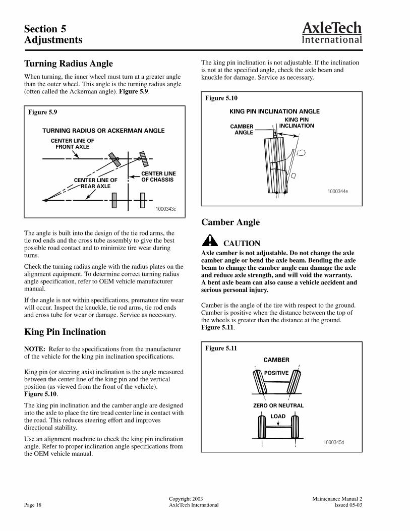
Turning Radius AngleWhen turning, the inner wheel must turn at a greater angle than the outer wheel. This angle is the turning radius angle (often called the Ackerman angle). Figure 5.9.
The angle is built into the design of the tie rod arms, thetie rod ends and the cross tube assembly to give the best possible road contact and to minimize tire wear during turns.
Check the turning radius angle with the radius plates on the alignment equipment. To determine correct turning radius angle specification, refer to OEM vehicle manufacturer manual.
If the angle is not within specifications, premature tire wear will occur. Inspect the knuckle, tie rod arms, tie rod ends and cross tube for wear or damage. Service as necessary.
King Pin Inclination
NOTE: Refer to the specifications from the manufacturer of the vehicle for the king pin inclination specifications.
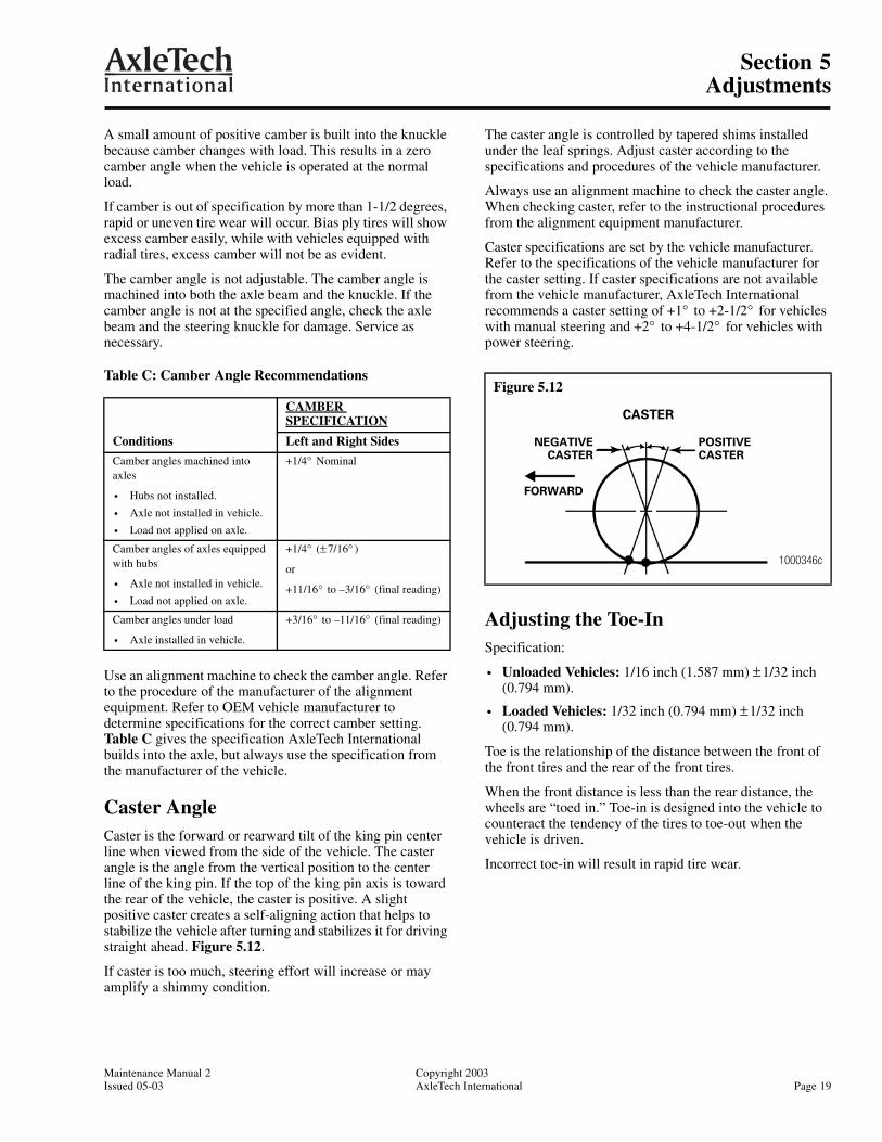
King pin (or steering axis) inclination is the angle measured between the center line of the king pin and the vertical position (as viewed from the front of the vehicle). Figure 5.10.
The king pin inclination and the camber angle are designed into the axle to place the tire tread center line in contact with the road. This reduces steering effort and improves directional stability.
Use an alignment machine to check the king pin inclination angle. Refer to proper inclination angle specifications from the OEM vehicle manual.
The king pin inclination is not adjustable. If the inclination is not at the specified angle, check the axle beam and knuckle for damage. Service as necessary.
Camber Angle
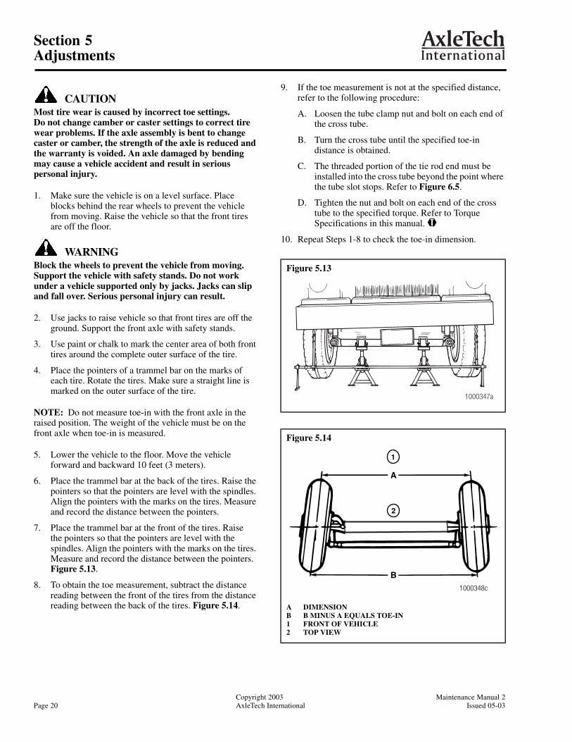
CAUTIONAxle camber is not adjustable. Do not change the axle camber angle or bend the axle beam. Bending the axle beam to change the camber angle can damage the axle and reduce axle strength, and will void the warranty. A bent axle beam can also cause a vehicle accident and serious personal injury.
Camber is the angle of the tire with respect to the ground. Camber is positive when the distance between the top of the wheels is greater than the distance at the ground.Figure 5.11.
Figure 5.9
CENTER LINE OFFRONT AXLE
1000343c
CENTER LINEOF CHASSISCENTER LINE OF
REAR AXLE
TURNING RADIUS OR ACKERMAN ANGLE
Figure 5.10
Figure 5.11
1000344e
CAMBERANGLE
KING PININCLINATION
KING PIN INCLINATION ANGLE
1000345d
LOAD
POSITIVE
ZERO OR NEUTRAL
CAMBER
Section 5Adjustments
Maintenance Manual 2 Copyright 2003Issued 05-03 AxleTech International Page 19
A small amount of positive camber is built into the knuckle because camber changes with load. This results in a zero camber angle when the vehicle is operated at the normal load.
If camber is out of specification by more than 1-1/2 degrees, rapid or uneven tire wear will occur. Bias ply tires will show excess camber easily, while with vehicles equipped with radial tires, excess camber will not be as evident.
The camber angle is not adjustable. The camber angle is machined into both the axle beam and the knuckle. If the camber angle is not at the specified angle, check the axle beam and the steering knuckle for damage. Service as necessary.
Table C: Camber Angle Recommendations
Use an alignment machine to check the camber angle. Refer to the procedure of the manufacturer of the alignment equipment. Refer to OEM vehicle manufacturer to determine specifications for the correct camber setting. Table C gives the specification AxleTech International builds into the axle, but always use the specification from the manufacturer of the vehicle.
Caster AngleCaster is the forward or rearward tilt of the king pin center line when viewed from the side of the vehicle. The caster angle is the angle from the vertical position to the center line of the king pin. If the top of the king pin axis is toward the rear of the vehicle, the caster is positive. A slight positive caster creates a self-aligning action that helps to stabilize the vehicle after turning and stabilizes it for driving straight ahead. Figure 5.12.
If caster is too much, steering effort will increase or may amplify a shimmy condition.
The caster angle is controlled by tapered shims installed under the leaf springs. Adjust caster according to the specifications and procedures of the vehicle manufacturer.
Always use an alignment machine to check the caster angle. When checking caster, refer to the instructional procedures from the alignment equipment manufacturer.
Caster specifications are set by the vehicle manufacturer. Refer to the specifications of the vehicle manufacturer for the caster setting. If caster specifications are not available from the vehicle manufacturer, AxleTech International recommends a caster setting of +1° to +2-1/2° for vehicles with manual steering and +2° to +4-1/2° for vehicles with power steering.
Adjusting the Toe-InSpecification:
• Unloaded Vehicles: 1/16 inch (1.587 mm) ± 1/32 inch (0.794 mm).
• Loaded Vehicles: 1/32 inch (0.794 mm) ± 1/32 inch (0.794 mm).
Toe is the relationship of the distance between the front of the front tires and the rear of the front tires.
When the front distance is less than the rear distance, the wheels are “toed in.” Toe-in is designed into the vehicle to counteract the tendency of the tires to toe-out when the vehicle is driven.
Incorrect toe-in will result in rapid tire wear.
Conditions
CAMBER SPECIFICATION
Left and Right Sides
Camber angles machined into axles
• Hubs not installed.
• Axle not installed in vehicle.
• Load not applied on axle.
+1/4° Nominal
Camber angles of axles equipped with hubs
• Axle not installed in vehicle.
• Load not applied on axle.
+1/4° (± 7/16° )
or
+11/16° to –3/16° (final reading)
Camber angles under load
• Axle installed in vehicle.
+3/16° to –11/16° (final reading)
Figure 5.12
FORWARD
1000346c
NEGATIVECASTER
POSITIVECASTER
CASTER
Section 5Adjustments
Copyright 2003 Maintenance Manual 2Page 20 AxleTech International Issued 05-03
CAUTIONMost tire wear is caused by incorrect toe settings. Do not change camber or caster settings to correct tire wear problems. If the axle assembly is bent to change caster or camber, the strength of the axle is reduced and the warranty is voided. An axle damaged by bending may cause a vehicle accident and result in serious personal injury.
1. Make sure the vehicle is on a level surface. Place blocks behind the rear wheels to prevent the vehicle from moving. Raise the vehicle so that the front tires are off the floor.
WARNINGBlock the wheels to prevent the vehicle from moving. Support the vehicle with safety stands. Do not work under a vehicle supported only by jacks. Jacks can slip and fall over. Serious personal injury can result.
2. Use jacks to raise vehicle so that front tires are off the ground. Support the front axle with safety stands.
3. Use paint or chalk to mark the center area of both front tires around the complete outer surface of the tire.
4. Place the pointers of a trammel bar on the marks of each tire. Rotate the tires. Make sure a straight line is marked on the outer surface of the tire.
NOTE: Do not measure toe-in with the front axle in the raised position. The weight of the vehicle must be on the front axle when toe-in is measured.
5. Lower the vehicle to the floor. Move the vehicle forward and backward 10 feet (3 meters).
6. Place the trammel bar at the back of the tires. Raise the pointers so that the pointers are level with the spindles. Align the pointers with the marks on the tires. Measure and record the distance between the pointers.
7. Place the trammel bar at the front of the tires. Raisethe pointers so that the pointers are level with the spindles. Align the pointers with the marks on the tires. Measure and record the distance between the pointers.Figure 5.13.
8. To obtain the toe measurement, subtract the distance reading between the front of the tires from the distance reading between the back of the tires. Figure 5.14.
9. If the toe measurement is not at the specified distance, refer to the following procedure:
A. Loosen the tube clamp nut and bolt on each end of the cross tube.
B. Turn the cross tube until the specified toe-in distance is obtained.
C. The threaded portion of the tie rod end must be installed into the cross tube beyond the point where the tube slot stops. Refer to Figure 6.5.
D. Tighten the nut and bolt on each end of the cross tube to the specified torque. Refer to Torque Specifications in this manual. @
10. Repeat Steps 1-8 to check the toe-in dimension.
Figure 5.13
Figure 5.14
A DIMENSIONB B MINUS A EQUALS TOE-IN1 FRONT OF VEHICLE2 TOP VIEW
1000347a
1
A
1000348c
B
2
Section 6Removal
Maintenance Manual 2 Copyright 2003Issued 05-03 AxleTech International Page 21
Section 6Removal
Removing the Wheel Ends
WARNINGBlock the wheels to prevent the vehicle from moving. Support the vehicle with safety stands. Do not work under a vehicle supported only by jacks. Jacks can slip and fall over. Serious personal injury can result.
1. Raise the front of the vehicle until the front wheels are off the floor. Support the vehicle with safety stands.
2. Remove the capscrews that fasten the cap to the hub. Remove the cap and the gasket.
NOTE: When the adjusting nuts are tightened or loosened, always use the correct size socket to avoid damaging the nut.
3. Remove the fasteners for the wheel bearings. Refer to the following procedure.
Double Nut and Lock Fasteners
A. Bend the tabs of the flattened lock washer away from the wheel bearing nut and the adjusting nut. Figure 6.1.
B. Remove the wheel bearing nut, the lock washer, the pierced lock ring and the adjusting nut from the knuckle. Figure 6.1.
4. Remove the outer wheel bearing cone from the hub.
5. Remove the wheel and tire, the hub and the drum as assembly.
6. Remove the brake components per the manufacturer’s procedures.
7. Remove the oil seal from the hub. Remove the inner wheel bearing cone.
8. Inspect the wheel bearings. Refer to Preparing the Parts for Assembly in this manual.
Removing the Drag Link
WARNINGTo prevent serious eye injury, always wear safe eye protection when you perform vehicle maintenance or service.
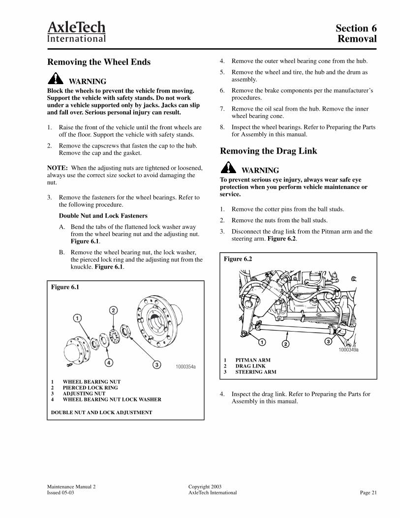
1. Remove the cotter pins from the ball studs.
2. Remove the nuts from the ball studs.
3. Disconnect the drag link from the Pitman arm and the steering arm. Figure 6.2.
4. Inspect the drag link. Refer to Preparing the Parts for Assembly in this manual.
Figure 6.1
1 WHEEL BEARING NUT2 PIERCED LOCK RING3 ADJUSTING NUT4 WHEEL BEARING NUT LOCK WASHER
DOUBLE NUT AND LOCK ADJUSTMENT
1000354a
Figure 6.2
1 PITMAN ARM2 DRAG LINK3 STEERING ARM
1000349a
Section 6Removal
Copyright 2003 Maintenance Manual 2Page 22 AxleTech International Issued 05-03
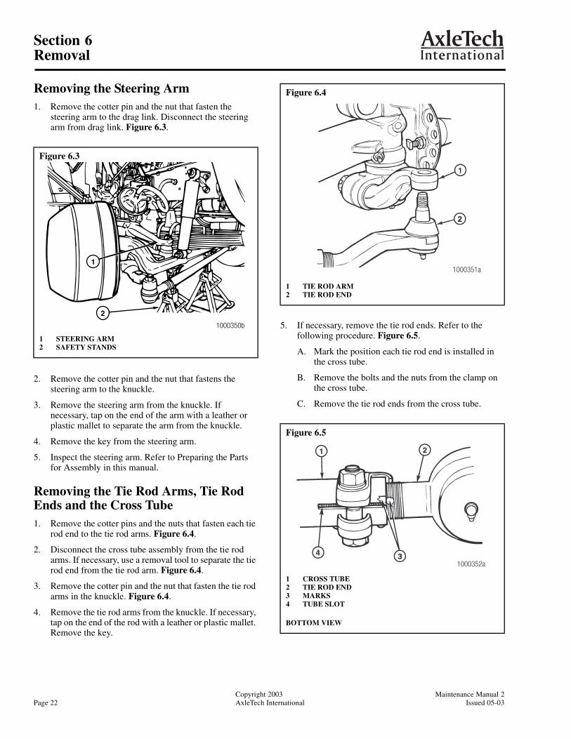
Removing the Steering Arm1. Remove the cotter pin and the nut that fasten the
steering arm to the drag link. Disconnect the steering arm from drag link. Figure 6.3.
2. Remove the cotter pin and the nut that fastens the steering arm to the knuckle.
3. Remove the steering arm from the knuckle. If necessary, tap on the end of the arm with a leather or plastic mallet to separate the arm from the knuckle.
4. Remove the key from the steering arm.
5. Inspect the steering arm. Refer to Preparing the Parts for Assembly in this manual.
Removing the Tie Rod Arms, Tie Rod Ends and the Cross Tube1. Remove the cotter pins and the nuts that fasten each tie
rod end to the tie rod arms. Figure 6.4.
2. Disconnect the cross tube assembly from the tie rod arms. If necessary, use a removal tool to separate the tie rod end from the tie rod arm. Figure 6.4.
3. Remove the cotter pin and the nut that fasten the tie rod arms in the knuckle. Figure 6.4.
4. Remove the tie rod arms from the knuckle. If necessary, tap on the end of the rod with a leather or plastic mallet. Remove the key.
5. If necessary, remove the tie rod ends. Refer to the following procedure. Figure 6.5.
A. Mark the position each tie rod end is installed in the cross tube.
B. Remove the bolts and the nuts from the clamp on the cross tube.
C. Remove the tie rod ends from the cross tube.
Figure 6.3
1 STEERING ARM2 SAFETY STANDS
1
2
1000350b
Figure 6.4
1 TIE ROD ARM2 TIE ROD END
Figure 6.5
1 CROSS TUBE2 TIE ROD END3 MARKS4 TUBE SLOT
BOTTOM VIEW
1000351a
1000352a
Section 6Removal
Maintenance Manual 2 Copyright 2003Issued 05-03 AxleTech International Page 23
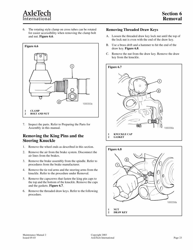
6. The rotating style clamp on cross tubes can be rotated for easier accessibility when removing the clamp bolt and nut. Figure 6.6.
7. Inspect the parts. Refer to Preparing the Parts for Assembly in this manual.
Removing the King Pins and the Steering Knuckle1. Remove the wheel ends as described in this section.
2. Remove the air from the brake system. Disconnect the air lines from the brakes.
3. Remove the brake assembly from the spindle. Refer to procedures from the brake manufacturer.
4. Remove the tie rod arms and the steering arms from the knuckle. Refer to the procedure under Removal.
5. Remove the capscrews that fasten the king pin caps to the top and the bottom of the knuckle. Remove the caps and the gaskets. Figure 6.7.
6. Remove the threaded draw keys. Refer to the following procedure.
Removing Threaded Draw Keys
A. Loosen the threaded draw key lock nut until the top of the lock nut is even with the end of the draw key.
B. Use a brass drift and a hammer to hit the end of the draw key. Figure 6.8.
C. Remove the nut from the draw key. Remove the draw key from the knuckle.
Figure 6.6
1 CLAMP2 BOLT AND NUT
1000353a
Figure 6.7
1 KNUCKLE CAP2 GASKET
Figure 6.8
1 NUT2 DRAW KEY
1000356a
1000358a
Section 6Removal
Copyright 2003 Maintenance Manual 2Page 24 AxleTech International Issued 05-03
WARNINGTo prevent serious eye injury, always wear safe eye protection when you perform vehicle maintenanceor service.
Use a brass or leather mallet for assembly and disassembly procedures. Do not hit steel parts with a steel hammer. Pieces of a part can break off and cause serious personal injury.
CAUTIONForce must be directly applied to the bottom of the nut and the end of the key. If force is not directly applied, the draw key will be damaged.
NOTE: If the bushings are not being replaced, perform the following to prevent damaging the bushings during king pin removal.
• Remove any flaring on the drift that may touch the bushings.
• Wrap tape to a thickness of 1/16 inch (1.5 mm) on the end of the drift.
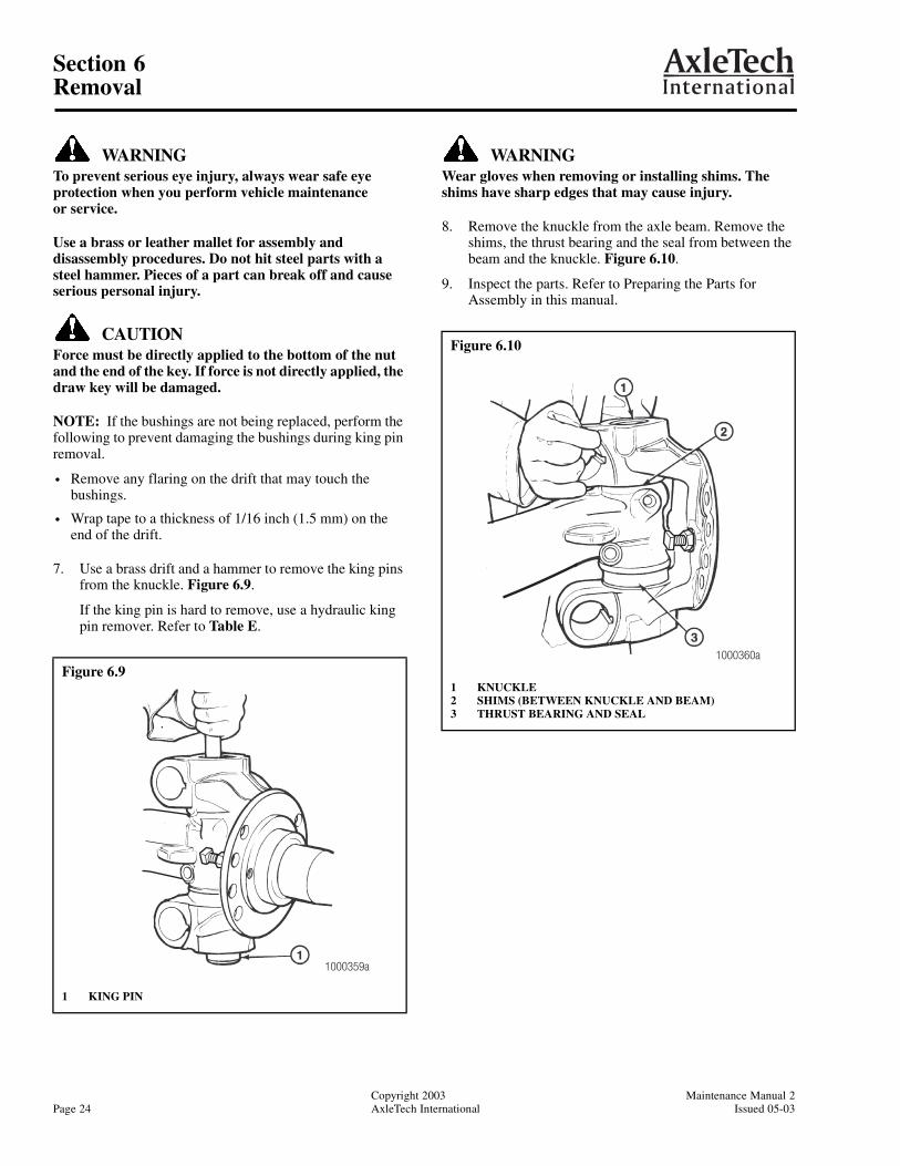
7. Use a brass drift and a hammer to remove the king pins from the knuckle. Figure 6.9.
If the king pin is hard to remove, use a hydraulic king pin remover. Refer to Table E.
WARNINGWear gloves when removing or installing shims. The shims have sharp edges that may cause injury.
8. Remove the knuckle from the axle beam. Remove the shims, the thrust bearing and the seal from between the beam and the knuckle. Figure 6.10.
9. Inspect the parts. Refer to Preparing the Parts for Assembly in this manual.
Figure 6.9
1 KING PIN
1000359a
Figure 6.10
1 KNUCKLE2 SHIMS (BETWEEN KNUCKLE AND BEAM)3 THRUST BEARING AND SEAL
1000360a
Section 6Removal
Maintenance Manual 2 Copyright 2003Issued 05-03 AxleTech International Page 25
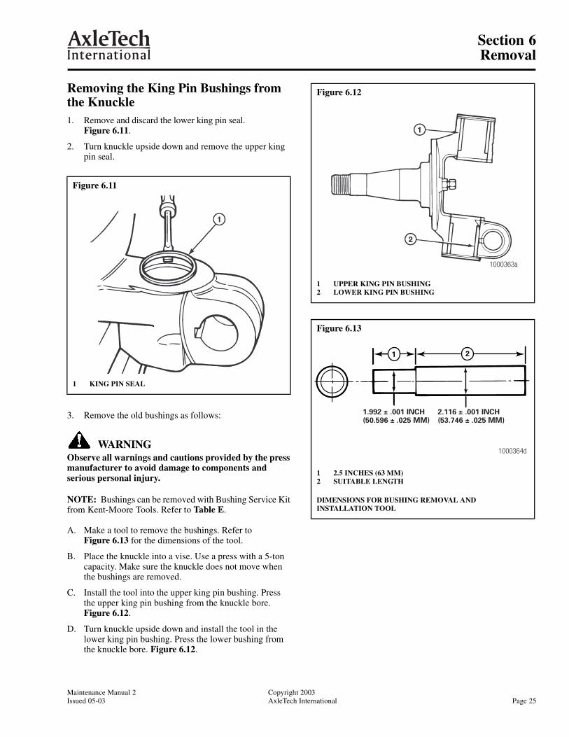
Removing the King Pin Bushings from the Knuckle1. Remove and discard the lower king pin seal.
Figure 6.11.
2. Turn knuckle upside down and remove the upper king pin seal.
3. Remove the old bushings as follows:
WARNINGObserve all warnings and cautions provided by the press manufacturer to avoid damage to components and serious personal injury.
NOTE: Bushings can be removed with Bushing Service Kit from Kent-Moore Tools. Refer to Table E.
A. Make a tool to remove the bushings. Refer to Figure 6.13 for the dimensions of the tool.
B. Place the knuckle into a vise. Use a press with a 5-ton capacity. Make sure the knuckle does not move when the bushings are removed.
C. Install the tool into the upper king pin bushing. Pressthe upper king pin bushing from the knuckle bore. Figure 6.12.
D. Turn knuckle upside down and install the tool in the lower king pin bushing. Press the lower bushing from the knuckle bore. Figure 6.12.
Figure 6.11
1 KING PIN SEAL
Figure 6.12
1 UPPER KING PIN BUSHING2 LOWER KING PIN BUSHING
Figure 6.13
1 2.5 INCHES (63 MM)2 SUITABLE LENGTH
DIMENSIONS FOR BUSHING REMOVAL AND INSTALLATION TOOL
1000363a
1000364d
21
1.992 ± .001 INCH(50.596 ± .025 MM)
2.116 ± .001 INCH(53.746 ± .025 MM)
Section 7Preparing the Parts for Assembly
Copyright 2003 Maintenance Manual 2Page 26 AxleTech International Issued 05-03
Section 7Preparing the Parts for Assembly
Repairing of Parts
WARNINGTo prevent serious eye injury, always wear safe eye protection when you perform vehicle maintenance or service.
The repair or reconditioning of front axle components is not allowed. AxleTech International recommends replacing damaged or out-of-specification components. All major components are heat treated and tempered.
CAUTIONDo not bend, weld or heat any front axle component. If the axle is bent, welded or heated, the strength of the axle is reduced and the warranty is voided. An axle damaged by bending, welding or heating may cause a vehicle accident and serious personal injury.
The following operations are prohibited on front axle components.
1. Welding of or to the steering arms, tie rod arms, the knuckles, the king pins, the axle beams, the tie rod assemblies, the hubs, the drums or the brakes.
2. Hot or cold bending of the knuckles, the steering arms, the tie rod arms, the ball studs, the axle beams or the tie rod assemblies.
3. Drilling out of the holes in the axle beam for the king pins.
4. Drilling out of the draw key holes in the knuckle.
5. Spray welding of bearing diameters on the knuckles or in the machined bores.
6. Milling or machining of any component.
WARNINGSolvent cleaners can be flammable, poisonous andcause burns. Examples of solvent cleaners are carbon tetrachloride, emulsion-type cleaners and petroleum-based cleaners. To avoid serious personal injury when you use solvent cleaners, you must carefully follow the manufacturer’s product instructions and these procedures:
• Wear safe eye protection.
• Wear clothing that protects your skin.
• Work in a well-ventilated area.
• Do not use gasoline, or solvents that contain gasoline. Gasoline can explode.
• You must use hot solution tanks or alkaline solutions correctly. Follow the manufacturer’s instructions carefully.
Cleaning the Ground or Polished PartsUse a cleaning solvent to clean ground or polished parts and surfaces. Kerosene or diesel fuel can be used for this purpose. DO NOT USE GASOLINE.
Do NOT clean ground or polished parts in a hot solution tank or with water, steam or alkaline solutions. These solutions will cause corrosion of the parts.
Cleaning the Rough PartsRough parts can be cleaned with the ground or polished parts. Rough parts also can be cleaned in hot solution tanks with a weak alkaline solution. Parts must remain in the hot solution tanks until they are completely cleaned and heated.
Drying the Cleaned PartsParts must be dried immediately after cleaning. Dry parts with clean paper or rags, or compressed air. Do not dry bearings by spinning with compressed air.
Preventing Corrosion on Cleaned PartsApply a light oil to cleaned and dried parts that are not damaged and are to be immediately assembled. Do NOT apply oil to the brake linings or the brake drums.
If parts are to be stored, apply a good corrosion preventative to all surfaces. Do NOT apply the material to the brake linings or the brake drums. Store the parts inside special paper or other material that prevents corrosion.
NOTE: Be sure that all tapered joints are clean and dry with no lubrication or corrosion preventative applied to mating surfaces.
Installing New Fasteners withPre-applied Adhesive Patches
WARNINGTo prevent serious eye injury, always wear safe eye protection when you perform vehicle maintenance or service.
1. Clean the oil and dirt from threaded holes. Use wire brush to remove old patch material. There is no special cleaning required.
Section 7Preparing the Parts for Assembly
Maintenance Manual 2 Copyright 2003Issued 05-03 AxleTech International Page 27
CAUTIONDo not apply adhesives or sealants on new fasteners with pre-applied adhesive patches or in the threaded holes. If other adhesives or sealants are used, the new adhesive will not function correctly.
2. Assemble parts using the new pre-applied adhesive fasteners.
NOTE: There is no drying time required for fasteners with pre-applied adhesive.
3. Tighten the fasteners to the required torque value for that size fastener. Refer to Torque Specifications in this manual.
Installing Original or Used Fasteners Using Loctite® 680 or Equivalent1. Clean the oil, dirt and old adhesive from all threads and
threaded holes. Use a wire brush.
CAUTIONDo not apply adhesive to fastener threads that will be installed into a closed bore. As the fastener is installed, air pressure will force adhesive applied to fastener out of the closed bore. Apply adhesive into threaded bore only.
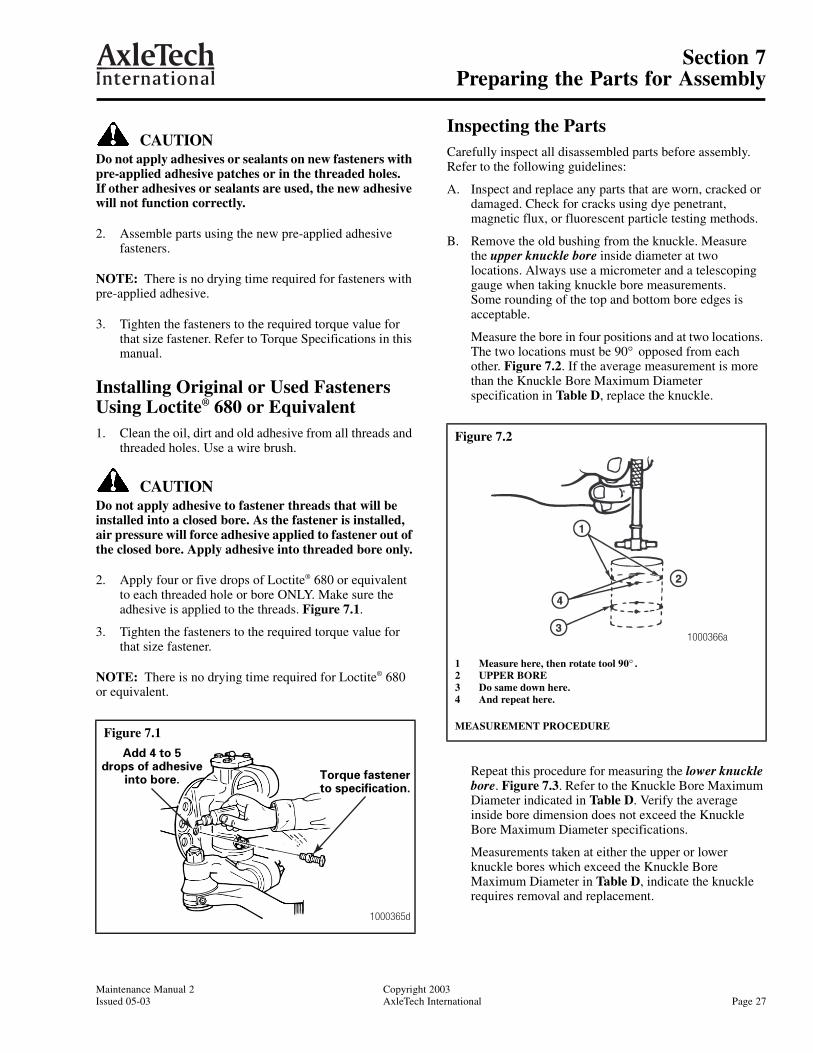
2. Apply four or five drops of Loctite® 680 or equivalent to each threaded hole or bore ONLY. Make sure the adhesive is applied to the threads. Figure 7.1.
3. Tighten the fasteners to the required torque value for that size fastener.
NOTE: There is no drying time required for Loctite® 680 or equivalent.
Inspecting the PartsCarefully inspect all disassembled parts before assembly. Refer to the following guidelines:
A. Inspect and replace any parts that are worn, cracked or damaged. Check for cracks using dye penetrant, magnetic flux, or fluorescent particle testing methods.
B. Remove the old bushing from the knuckle. Measure the upper knuckle bore inside diameter at two locations. Always use a micrometer and a telescoping gauge when taking knuckle bore measurements. Some rounding of the top and bottom bore edges is acceptable.
Measure the bore in four positions and at two locations. The two locations must be 90° opposed from each other. Figure 7.2. If the average measurement is more than the Knuckle Bore Maximum Diameter specification in Table D, replace the knuckle.
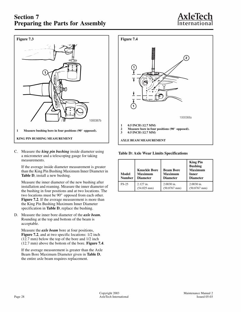
Repeat this procedure for measuring the lower knuckle bore. Figure 7.3. Refer to the Knuckle Bore Maximum Diameter indicated in Table D. Verify the average inside bore dimension does not exceed the Knuckle Bore Maximum Diameter specifications.
Measurements taken at either the upper or lower knuckle bores which exceed the Knuckle Bore Maximum Diameter in Table D, indicate the knuckle requires removal and replacement.
Figure 7.1
1000365d
Add 4 to 5drops of adhesive
into bore. Torque fastenerto specification.
Figure 7.2
1 Measure here, then rotate tool 90° .2 UPPER BORE3 Do same down here.4 And repeat here.
MEASUREMENT PROCEDURE
1000366a
Section 7Preparing the Parts for Assembly
Copyright 2003 Maintenance Manual 2Page 28 AxleTech International Issued 05-03
C. Measure the king pin bushing inside diameter using a micrometer and a telescoping gauge for taking measurements.
If the average inside diameter measurement is greater than the King Pin Bushing Maximum Inner Diameter in Table D, install a new bushing.
Measure the inner diameter of the new bushing after installation and reaming. Measure the inner diameter of the bushing in four positions and at two locations. The two locations must be 90° opposed from each other. Figure 7.2. If the average measurement is more than the King Pin Bushing Maximum Inner Diameter specification in Table D, replace the bushing.
D. Measure the inner bore diameter of the axle beam. Rounding at the top and bottom of the beam is acceptable.
Measure the axle beam bore at four positions, Figure 7.2, and at two specific locations: 1/2 inch(12.7 mm) below the top of the bore and 1/2 inch (12.7 mm) above the bottom of the bore. Figure 7.4.
If the average measurement is greater than the Axle Beam Bore Maximum Diameter given in Table D, the entire axle beam requires replacement.
Table D: Axle Wear Limits Specifications
Figure 7.3
1 Measure bushing bore in four positions (90° opposed).
KING PIN BUSHING MEASUREMENT
1000367b
1
Figure 7.4
1 0.5 INCH (12.7 MM)2 Measure bore in four positions (90° opposed).3 0.5 INCH (12.7 MM)
AXLE BEAM MEASUREMENT
Model Number
Knuckle Bore Maximum Diameter
Beam Bore Maximum Diameter
King Pin Bushing Maximum Inner Diameter
FS-25 2.127 in. (54.025 mm)
2.0030 in. (50.8767 mm)
2.0030 in. (50.8767 mm)
2
1
1
1000368a

Section 7Preparing the Parts for Assembly
Maintenance Manual 2 Copyright 2003Issued 05-03 AxleTech International Page 29
Inspecting the Wheel BearingsInspect the wheel bearings when the hub is removed from the knuckle spindle.
Remove all lubricant from the bearings, knuckle, hub and hubcap.
Inspect the cup, the cone and the rollers and cage of all bearings. If any of the following conditions exist, the bearing MUST be replaced.
1. The center of the large diameter end of the rollers is worn level or below the outer surface. Figure 7.5.
2. The radius at the large diameter end of the rollers is worn to a sharp edge. Figure 7.5.
3. A visible roller groove in the cup or the cone inner race surfaces. The groove can be seen at the small or large diameter end of both parts. Figure 7.6.
4. Deep cracks or breaks in the cup, the cone inner race or the roller surfaces. Figure 7.6.
5. Bright wear marks on the outer surface of the roller cage. Figure 7.7.
6. Damage on the rollers and on the surfaces of thecup and the cone inner race that touch the rollers. Figure 7.8.
7. Damage on the cup and the cone inner surfaces that touch the rollers. Figure 7.9.
Figure 7.5
1 WORN RADIUS2 WORN SURFACE
1000369a
Figure 7.6
Figure 7.7
Figure 7.8
Figure 7.9
1000370b
WEAR GROOVECRACK
WEAR MARKS
1000372b
ETCHING AND PITTING
1000373d
SPALLINGAND
FLAKING
Section 8Installation
Copyright 2003 Maintenance Manual 2Page 30 AxleTech International Issued 05-03
Section 8Installation
Installing Easy Steer™ King Pin Bushings in the Knuckle
Without a Press
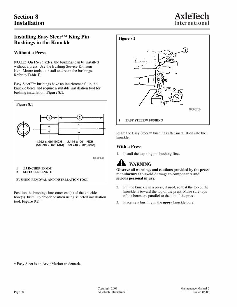
NOTE: On FS-25 axles, the bushings can be installed without a press. Use the Bushing Service Kit from Kent-Moore tools to install and ream the bushings. Refer to Table E.
Easy Steer™* bushings have an interference fit in the knuckle bores and require a suitable installation tool for bushing installation. Figure 8.1.
Position the bushings into outer end(s) of the knuckle bore(s). Install to proper position using selected installation tool. Figure 8.2.
* Easy Steer is an ArvinMeritor trademark.
Ream the Easy Steer™ bushings after installation into the knuckle.
With a Press
1. Install the top king pin bushing first.
WARNINGObserve all warnings and cautions provided by the press manufacturer to avoid damage to components and serious personal injury.
2. Put the knuckle in a press, if used, so that the top of the knuckle is toward the top of the press. Make sure tops of the bores are parallel to the top of the press.
3. Place new bushing in the upper knuckle bore.
Figure 8.1
1 2.5 INCHES (63 MM)2 SUITABLE LENGTH
BUSHING REMOVAL AND INSTALLATION TOOL
1000364e
21
1.992 ± .001 INCH(50.596 ± .025 MM)
2.116 ± .001 INCH(53.746 ± .025 MM)
Figure 8.2
1 EASY STEER™ BUSHING
1
1000375b
Section 8Installation
Maintenance Manual 2 Copyright 2003Issued 05-03 AxleTech International Page 31
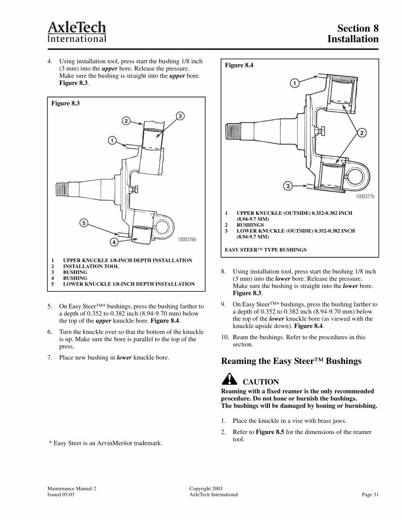
4. Using installation tool, press start the bushing 1/8 inch (3 mm) into the upper bore. Release the pressure.Make sure the bushing is straight into the upper bore. Figure 8.3.
5. On Easy Steer™* bushings, press the bushing farther to a depth of 0.352 to 0.382 inch (8.94-9.70 mm) below the top of the upper knuckle bore. Figure 8.4.
6. Turn the knuckle over so that the bottom of the knuckle is up. Make sure the bore is parallel to the top of the press.
7. Place new bushing in lower knuckle bore.
8. Using installation tool, press start the bushing 1/8 inch (3 mm) into the lower bore. Release the pressure. Make sure the bushing is straight into the lower bore. Figure 8.3.
9. On Easy Steer™* bushings, press the bushing farther to a depth of 0.352 to 0.382 inch (8.94-9.70 mm) below the top of the lower knuckle bore (as viewed with the knuckle upside down). Figure 8.4.
10. Ream the bushings. Refer to the procedures in this section.
Reaming the Easy Steer™ Bushings
CAUTIONReaming with a fixed reamer is the only recommended procedure. Do not hone or burnish the bushings. The bushings will be damaged by honing or burnishing.
1. Place the knuckle in a vise with brass jaws.
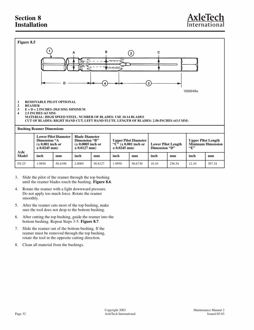
2. Refer to Figure 8.5 for the dimensions of the reamer tool.
Figure 8.3
1 UPPER KNUCKLE 1/8-INCH DEPTH INSTALLATION2 INSTALLATION TOOL3 BUSHING4 BUSHING5 LOWER KNUCKLE 1/8-INCH DEPTH INSTALLATION
1000376b
Figure 8.4
1 UPPER KNUCKLE (OUTSIDE) 0.352-0.382 INCH (8.94-9.7 MM)
2 BUSHINGS3 LOWER KNUCKLE (OUTSIDE) 0.352-0.382 INCH
(8.94-9.7 MM)
EASY STEER™ TYPE BUSHINGS
1000377b
* Easy Steer is an ArvinMeritor trademark.
Section 8Installation
Copyright 2003 Maintenance Manual 2Page 32 AxleTech International Issued 05-03
3. Slide the pilot of the reamer through the top bushing until the reamer blades touch the bushing. Figure 8.6.
4. Rotate the reamer with a light downward pressure. Do not apply too much force. Rotate the reamer smoothly.
5. After the reamer cuts most of the top bushing, make sure the tool does not drop to the bottom bushing.
6. After cutting the top bushing, guide the reamer into the bottom bushing. Repeat Steps 3-5. Figure 8.7.
7. Slide the reamer out of the bottom bushing. If the reamer must be removed through the top bushing, rotate the tool in the opposite cutting direction.
8. Clean all material from the bushings.
Figure 8.5
1 REMOVABLE PILOT OPTIONAL2 REAMER3 E = D + 2 INCHES (50.8 MM) MINIMUM4 2.5 INCHES (63 MM) MATERIAL: HIGH SPEED STEEL. NUMBER OF BLADES: USE 10-14 BLADES CUT OF BLADES: RIGHT HAND CUT, LEFT HAND FLUTE. LENGTH OF BLADES: 2.50-INCHES (63.5 MM)
Bushing Reamer Dimensions
Axle Model
Lower Pilot Diameter Dimension “A(± 0.001 inch or ± 0.0245 mm)
Blade Diameter Dimension “B” (± 0.0005 inch or ± 0.0127 mm)
Upper Pilot Diameter “C” (± 0.001 inch or ± 0.0245 mm)
Lower Pilot Length Dimension “D”
Upper Pilot Length Minimum Dimension “E”
inch mm inch mm inch mm inch mm inch mm
FS-25 1.9850 50.4190 2.0005 50.8127 1.9950 50.6730 10.10 256.54 12.10 307.34
BA C
D
2
34
1
1000049a
Section 8Installation
Maintenance Manual 2 Copyright 2003Issued 05-03 AxleTech International Page 33
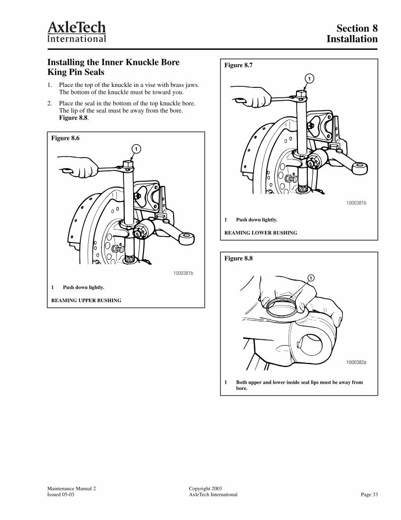
Installing the Inner Knuckle Bore King Pin Seals1. Place the top of the knuckle in a vise with brass jaws.
The bottom of the knuckle must be toward you.
2. Place the seal in the bottom of the top knuckle bore. The lip of the seal must be away from the bore. Figure 8.8.
Figure 8.6
1 Push down lightly.
REAMING UPPER BUSHING
1000381b
1
Figure 8.7
1 Push down lightly.
REAMING LOWER BUSHING
Figure 8.8
1 Both upper and lower inside seal lips must be away from bore.
1000381b
1
1000382a
Section 8Installation
Copyright 2003 Maintenance Manual 2Page 34 AxleTech International Issued 05-03
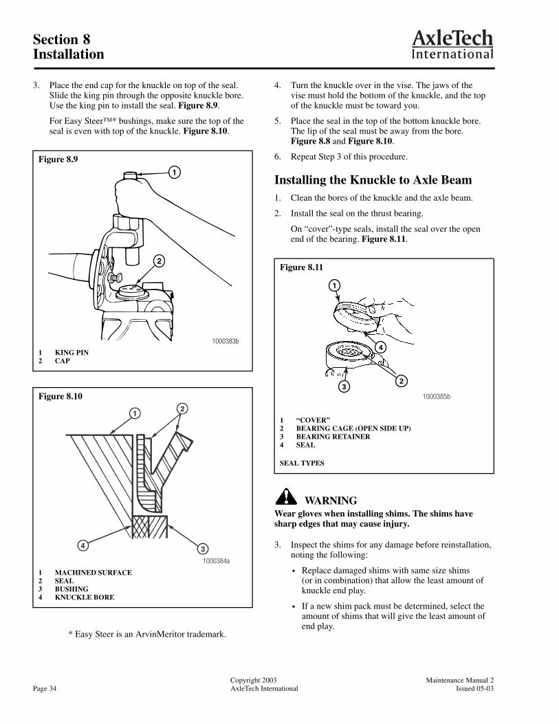
3. Place the end cap for the knuckle on top of the seal. Slide the king pin through the opposite knuckle bore. Use the king pin to install the seal. Figure 8.9.
For Easy Steer™* bushings, make sure the top of the seal is even with top of the knuckle. Figure 8.10.
4. Turn the knuckle over in the vise. The jaws of the vise must hold the bottom of the knuckle, and the top of the knuckle must be toward you.
5. Place the seal in the top of the bottom knuckle bore. The lip of the seal must be away from the bore.Figure 8.8 and Figure 8.10.
6. Repeat Step 3 of this procedure.
Installing the Knuckle to Axle Beam1. Clean the bores of the knuckle and the axle beam.
2. Install the seal on the thrust bearing.
On “cover”-type seals, install the seal over the open end of the bearing. Figure 8.11.
WARNINGWear gloves when installing shims. The shims have sharp edges that may cause injury.
3. Inspect the shims for any damage before reinstallation, noting the following:
• Replace damaged shims with same size shims (or in combination) that allow the least amount of knuckle end play.
• If a new shim pack must be determined, select the amount of shims that will give the least amount of end play.
Figure 8.9
1 KING PIN2 CAP
Figure 8.10
1 MACHINED SURFACE2 SEAL3 BUSHING4 KNUCKLE BORE
1
1000383b
2
1000384a
Figure 8.11
1 “COVER”2 BEARING CAGE (OPEN SIDE UP)3 BEARING RETAINER4 SEAL
SEAL TYPES
32
4
1
1000385b
* Easy Steer is an ArvinMeritor trademark.

Section 8Installation
Maintenance Manual 2 Copyright 2003Issued 05-03 AxleTech International Page 35
4. After inspection, place shims on top of axle beam bore machined surface. Align shims for king pin installation.
5. Place the knuckle on the axle beam.
6. Place a pry bar between the steering arm boss and the axle beam. Lift the knuckle and slide the shim pack between the top of the beam and the knuckle. Figure 8.12.
• Make sure all the bores are aligned. If the bores are not aligned, the parts will be damaged when the king pin is installed.
• Remove the pry bar.
7. Before installing the king pin into the top of the knuckle, be sure to note the following:
A. Apply the specified lubricant to bottom half of king pin.
B. Before placing the king pin into the top of the knuckle, be sure the word “TOP” (which is stamped on the king pin) can be seen. Figure 8.13.
C. Rotate king pin so that two draw key slots of pin properly align with draw key slots in the knuckle.
CAUTIONDo not force the pin through the top bushing or the shims will be damaged.
8. Install the king pin into the top of the knuckle and through the area where shims are located.
WARNINGTo prevent serious eye injury, always wear safe eye protection when you perform vehicle maintenance or service.
Use a brass or leather mallet for assembly and disassembly procedures. Do not hit steel parts with a steel hammer. Pieces of a part can break off and cause serious personal injury.
9. If required, use a hammer and a brass drift to apply direct force to king pin for seating it into the lower knuckle bore.
NOTE:
• Do not drive or tighten the draw keys into the knuckle until the end play is checked and adjusted.
• FS-25 model uses threaded draw keys.
10. Seat top draw key into front of beam. Seat bottom draw key in back of beam by striking with hammer and drift. Make sure keys align with slots of king pin. Do not install or tighten lock nuts before checking the knuckle end play. Refer to Figure 8.14.
Figure 8.12
1 PRY BAR2 SHIM
1000388a
Figure 8.13
1 “TOP”2 KING PIN
1000389a
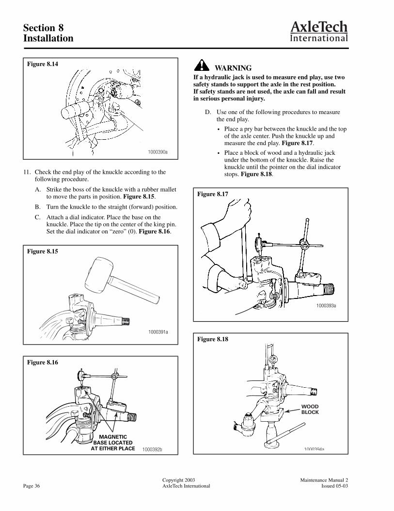
Section 8Installation
Copyright 2003 Maintenance Manual 2Page 36 AxleTech International Issued 05-03
11. Check the end play of the knuckle according to the following procedure.
A. Strike the boss of the knuckle with a rubber mallet to move the parts in position. Figure 8.15.
B. Turn the knuckle to the straight (forward) position.
C. Attach a dial indicator. Place the base on the knuckle. Place the tip on the center of the king pin. Set the dial indicator on “zero” (0). Figure 8.16.
WARNINGIf a hydraulic jack is used to measure end play, use two safety stands to support the axle in the rest position. If safety stands are not used, the axle can fall and result in serious personal injury.
D. Use one of the following procedures to measure the end play.
• Place a pry bar between the knuckle and the top of the axle center. Push the knuckle up and measure the end play. Figure 8.17.
• Place a block of wood and a hydraulic jack under the bottom of the knuckle. Raise the knuckle until the pointer on the dial indicator stops. Figure 8.18.
Figure 8.14
Figure 8.15
Figure 8.16
1000390a
1000391a
1000392b
MAGNETICBASE LOCATED
AT EITHER PLACE
Figure 8.17
Figure 8.18
1000393a
WOODBLOCK
1000394a
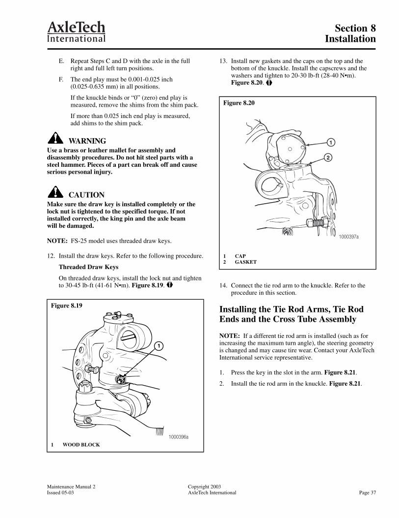
Section 8Installation
Maintenance Manual 2 Copyright 2003Issued 05-03 AxleTech International Page 37
E. Repeat Steps C and D with the axle in the fullright and full left turn positions.
F. The end play must be 0.001-0.025 inch (0.025-0.635 mm) in all positions.
If the knuckle binds or “0” (zero) end play is measured, remove the shims from the shim pack.
If more than 0.025 inch end play is measured, add shims to the shim pack.
WARNINGUse a brass or leather mallet for assembly and disassembly procedures. Do not hit steel parts with a steel hammer. Pieces of a part can break off and cause serious personal injury.
CAUTIONMake sure the draw key is installed completely or the lock nut is tightened to the specified torque. If not installed correctly, the king pin and the axle beam will be damaged.
NOTE: FS-25 model uses threaded draw keys.
12. Install the draw keys. Refer to the following procedure.
Threaded Draw Keys
On threaded draw keys, install the lock nut and tighten to 30-45 lb-ft (41-61 N•m). Figure 8.19. @
13. Install new gaskets and the caps on the top and the bottom of the knuckle. Install the capscrews and the washers and tighten to 20-30 lb-ft (28-40 N•m).Figure 8.20. @
14. Connect the tie rod arm to the knuckle. Refer to the procedure in this section.
Installing the Tie Rod Arms, Tie Rod Ends and the Cross Tube Assembly
NOTE: If a different tie rod arm is installed (such as for increasing the maximum turn angle), the steering geometry is changed and may cause tire wear. Contact your AxleTech International service representative.
1. Press the key in the slot in the arm. Figure 8.21.
2. Install the tie rod arm in the knuckle. Figure 8.21.
Figure 8.19
1 WOOD BLOCK
1
1000396a
Figure 8.20
1 CAP2 GASKET
1000397a

Section 8Installation
Copyright 2003 Maintenance Manual 2Page 38 AxleTech International Issued 05-03
CAUTIONTighten the nuts to the specified torque. If the nuts are not tightened to the specified torque, the parts will be damaged.
3. Install the nut on the tie rod arm. Tighten to the specified torque. Refer to Torque Specifications in this manual. @
4. Install the cotter pins. If necessary, tighten the nut slightly, increasing the final torque value until the holes are aligned. Do not loosen the nut to install the cotter pin.
NOTE: The cross tube has right-hand threads on one end and left-hand threads on the other end. Make sure the ends are installed on the tube.
5. If removed, install the tie rod ends on the cross tube to the position marked during removal. Figure 8.22.
If new tie rod ends are installed, thread the ends equally on the cross tube to the required length.
6. Install the nuts and the bolts in the clamps. Tighten to the specified torque. Refer to Torque Specifications in this manual. Figure 8.22.
7. The rotating style clamp on cross tubes can be rotated for easier accessibility when installing the clamp bolt and nut. Tighten nut sufficiently to engage the locking element of the nut with the bolt. Clamp and tie rod end must be free to rotate. Make certain the clamp tab is firmly seated against the cross tube. Figure 8.23.
8. Clean and dry tie rod taper and connect the tie rod ends into the tie rod arms. The threaded portion of the tie rod end must be installed into the cross tube beyond the end of the slot. Make certain the clamp tab is firmly seated against the cross tube.
9. Install the nuts on the tie rod ends. Tighten to the specified torque. Refer to Torque Specifications in this manual. @
Figure 8.21
1 KNUCKLE TIE ROD ARM2 TIE ROD END
2
1
1003284a
Figure 8.22
Figure 8.23
1 TIE ROD END2 CLAMP3 CROSS TUBE4 BOLT AND NUT
BOTTOM VIEW
1003281a
Tie rod end isinstalled past
cross tube slot.TIE ROD
END
MARKSCROSSTUBE
TUBESLOT
1
2 3
4
1003283a

Section 8Installation
Maintenance Manual 2 Copyright 2003Issued 05-03 AxleTech International Page 39
10. Install the cotter pins. If necessary, tighten the nut until the holes are aligned. Do not loosen the nut to install the cotter pin.
11. Check and, if necessary, adjust the toe-in. Refer to Adjustments in this manual.
Installing the Steering Arm1. Press the key in the slot in the arm.
2. Install the steering arm in the knuckle. Figure 8.24.
CAUTIONTighten the nuts to the specified torque. If the nuts are not tightened to the specified torque, the parts will be damaged.
3. Install the nuts. Tighten to the specified torque. Refer to Torque Specifications in this manual. @
4. Install the cotter pins. If necessary, tighten the nut until the holes are aligned. Do not loosen the nut to install the cotter pin.
5. Lubricate the drag link end that connects to steering arm. Refer to Lubrication and Maintenance in this manual.
6. Check for correct operation.
Installing the Drag Link1. Connect the drag link to the steering arm. Figure 8.25.
2. Connect the drag link to the Pitman arm. Figure 8.25.
CAUTIONTighten the nuts to the specified torque. If the nuts are not tightened to the specified torque, the parts will be damaged.
3. Install the nuts. Tighten to the specified torque. Refer to Torque Specifications in this manual. @
4. Install the cotter pins. If necessary, tighten the nut until the holes are aligned. Do not loosen the nut to install the cotter pin.
5. Lubricate the drag link. Refer to Lubrication and Maintenance in this manual.
6. Check for correct operation.
Figure 8.24
1 STEERING ARM2 SAFETY STANDS
1
2
1000350b
Figure 8.25
1 PITMAN ARM2 DRAG LINK3 STEERING ARM
1
2
31000402a
Section 8Installation
Copyright 2003 Maintenance Manual 2Page 40 AxleTech International Issued 05-03
Installing the Brake Components and Wheel Ends
1. Install the brake assembly on the knuckle. Refer to the procedure from the manufacturer of the vehicle.
2. Lubricate the wheel bearings. Refer to Lubrication and Maintenance in this manual.
3. Install the wheel and tire assembly.
4. Lubricate the wheel bearings. Refer to Lubrication and Maintenance in this manual.
5. Install the outer wheel bearing cone in the hub. Install the adjusting nut.
6. Adjust the wheel bearings. Refer to the wheel end hardware manufacturer’s procedures.
7. Install the cap and the gasket on the hub. Installthe capscrews and tighten to 20-30 lb-ft (27-41 N•m). @
8. Lower the vehicle to the ground. Check for correct operation.
9. Check and adjust the toe-in. Refer to Adjustments in this manual.
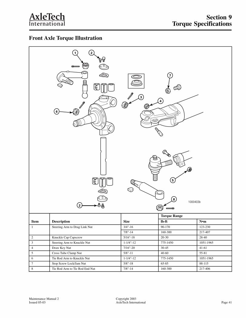
Section 9Torque Specifications
Maintenance Manual 2 Copyright 2003Issued 05-03 AxleTech International Page 41
Section 9Torque Specifications
Front Axle Torque Illustration
1000403b
1 2
3
7
4
8
5
2
6
Item Description Size
Torque Range
lb-ft N•m
1 Steering Arm to Drag Link Nut 3/4"-16 90-170 123-230
7/8"-14 160-300 217-407
2 Knuckle Cap Capscrew 5/16"-18 20-30 28-40
3 Steering Arm to Knuckle Nut 1-1/4"-12 775-1450 1051-1965
4 Draw Key Nut 7/16"-20 30-45 41-61
5 Cross Tube Clamp Nut 5/8"-11 40-60 55-81
6 Tie Rod Arm to Knuckle Nut 1-1/4"-12 775-1450 1051-1965
7 Stop Screw Lock/Jam Nut 5/8"-18 65-85 88-115
8 Tie Rod Arm to Tie Rod End Nut 7/8"-14 160-300 217-406

Section 10Special Tools
Copyright 2003 Maintenance Manual 2Page 42 AxleTech International Issued xx-03
Section 10Special Tools
Table E: Special Tools
Description Kent-Moore Tool Numbera Owatonna Tool Numberb Snap-On® Tool Numberc
King Pin Remover J 36136 4240 20 Ton: CG430HYB
35 Ton: CG730HY
King Pin Bushing Service Kit
Basic Service Kit
FS-25 Series Kit
d
PT 4375
PT 4370-20
—
—
—
—
a Order Kent-Moore tools from: Kent-Moore, 28635 Mound Road, Warren, MI 48092.
b Order Owatonna tools from OTC Toll and Equipment Division, 655 Eisenhower Drive, Owatonna, MN 55060.
c See your local Snap-On® dealer.
d Use Basic Service Kit along with the correct axle series kit.


MM2Issued 05-03
Suite 4003001 West Big Beaver RoadTroy, Michigan 48084U.S.A.877-877-9717FAX: 248-435-1990Website: www.axletech.com
© Copyright AxleTech InternationalPrinted in the USA
AxleTech, International France4, Rue Jean ServantonBoite Postale 65642042 Saint Etienne Cedex 1France(33) 477.92.88.00FAX: (33) 477.92.88.93
AxleTech Do Brasil Sistemas Automotivos Ltda.Avendia Joao Batista, 830Centro-Osasco-SP06097095 BrasilPhone: +55 11 36846641FAX: +55 11 36846859