Embed Size (px)
Citation preview
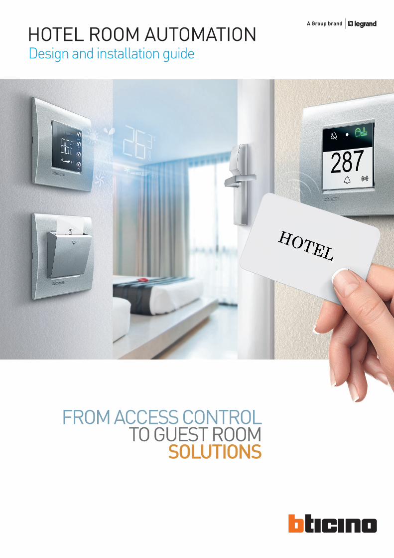
HOTEL ROOM AUTOMATION
FROM ACCESS CONTROL TO GUEST ROOM
SOLUTIONS
Design and installation guide
2
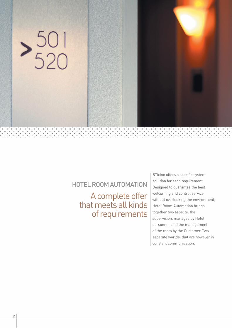
A complete offer that meets all kinds
of requirements
HOTEL ROOM AUTOMATIONBTicino offers a specific system solution for each requirement. Designed to guarantee the best welcoming and control service without overlooking the environment, Hotel Room Automation brings together two aspects: the supervision, managed by Hotel personnel, and the management of the room by the Customer. Two separate worlds, that are however in constant communication.

3WWW.BTICINO.COM
SCS- BUS SYSTEMHOTEL ROOM AUTOMATION
6-15General features
16-23General rules
for installation
Contents
33-45Catalogue
24-32Installation and
configuration
47-81Technical Sheets
4-5Numerical index
The functions in the room 7The supervision 8The main system components 10Customisation of the offer 12A solution for the hotels 14
Axolute 34Dimensional data 39Livinglight 40Dimensional data 45
Typical hotel system 22Typical wiring diagram for common areas and hotel rooms 24Variations of room diagrams 28
Technical and dimensional data, regulations, assembly and installation 47
Index by item code - page of reference 4
Maximum distances and absorptions 18Configuration 21“Hotelsupervision” supervision software 21

4
Numerical index
3476 36 - 42
3477 36 - 42
3510 36 - 42
3511 36 - 42
3512 36 - 42
3513 36 - 42
3515 36 - 42
3541 35 - 41
3542 35 - 41
336904 37 - 43
348210 36 - 42
348402 36 - 42
3501/0 37 - 43
3501/1 37 - 43
3501/2 37 - 43
3501/3 37 - 43
3501/4 37 - 43
3501/5 37 - 43
3501/6 37 - 43
3501/7 37 - 43
3501/8 37 - 43
3501/9 37 - 43
3501/AMB 37 - 43
3501/AUX 37 - 43
3501/CEN 37 - 43
3501/GEN 37 - 43
3501/GR 37 - 43
3501/OFF 37 - 43
3501/OI 37 - 43
3501/ON 37 - 43
3501/PUL 37 - 43
3501/SLA 37 - 43
3501/T 37 - 43
3501/TM 37 - 43
3501K 37 - 43
3501K/1 37 - 43
3510M 36 - 43
3510PB 36 - 43
3544SW 35 - 41
3546SW 35 - 41
E46ADCN 36 - 42
E49 36 - 42
F428 36 - 42
F430/2 35 - 41
F430/4 35 - 41
F430R3V10 35 - 41
F430R8 35 - 41
F430V10 35 - 41
F458 35 - 41
H4372V230H 38
H4548 38
H4549 38
H4648 35
H4649 35
H4650 35
H4651 35
H4652 35
H4653 35
H4691 35
HC4033 38
HC4177 38
HC4285C 38
HC4285C2 38
HC4547 38
HC4915BL 38
HC4915DD 38
HC4915M2BL 38
HC4915M2DD 38
HC4915MR 38
HC4921BL 38
HC4921DD 38
HC4921M2BL 38
HC4921MR 38
HD4033 38
Item ItemPage Page

5WWW.BTICINO.COM
SCS- BUS SYSTEMHOTEL ROOM AUTOMATION
HD4177 38
HD4285C 38
HD4285C2 38
HD4547 38
HD4915BL 38
HD4915DD 38
HD4915M2BL 38
HD4915M2DD 38
HD4915MR 38
HD4921BL 38
HD4921DD 38
HD4921M2BL 38
HD4921MR 38
HS4033 38
HS4177 38
HS4285C 38
HS4285C2 38
HS4547 38
HS4915BL 38
HS4915DD 38
HS4915M2BL 38
HS4915M2DD 38
HS4915MR 38
HS4921BL 38
HS4921DD 38
HS4921M2BL 38
HS4921MR 38
L4033 44
L4177 44
L4373H 44
L4547 44
L4551 44
L4669 37 - 43
L4669/500 37 - 43
L4669HF 37 - 43
L4669KM1 37 - 43
L4915DD 44
L4915M2DD 44
L4915MR 44
L4915SETBL 44
L4915TN 44
LN4548 44
LN4549 44
LN4648 41
LN4649 41
LN4650 41
LN4651 41
LN4652 41
LN4653 41
LN4691 41
MH201 35 - 41
N4033 44
N4177 44
N4373H 44
N4547 44
N4551 44
N4915DD 44
N4915M2DD 44
N4915MR 44
N4915SETBL 44
N4915TN 44
NT4033 44
NT4177 44
NT4373H 44
NT4547 44
NT4551 44
NT4915DD 44
NT4915M2DD 44
NT4915MR 44
NT4915SETBL 44
NT4915TN 44
Item ItemPage Page
6
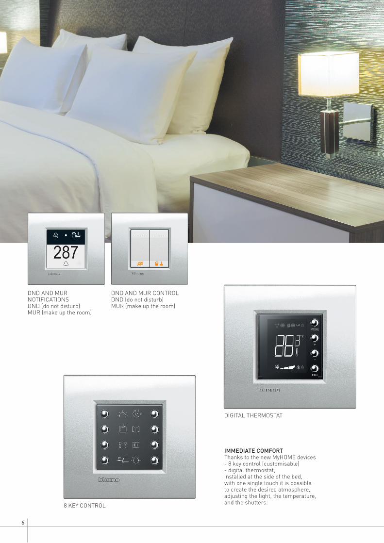
8 KEY CONTROL
IMMEDIATE COMFORTThanks to the new MyHOME devices- 8 key control (customisable)- digital thermostat,installed at the side of the bed, with one single touch it is possible to create the desired atmosphere, adjusting the light, the temperature, and the shutters.
DIGITAL THERMOSTAT
DND AND MUR NOTIFICATIONSDND (do not disturb)MUR (make up the room)
DND AND MUR CONTROLDND (do not disturb)MUR (make up the room)

7WWW.BTICINO.COM
SCS- BUS SYSTEMHOTEL ROOM AUTOMATION
SAFETY AT THE TOPProtected shaver socket, step marker lamps for the night, and bathroom pull cords. Guarantee of maximum safety at any time during the stay.
A/V SOCKETS USB CHARGER SOCKET
STEP MARKER LAMPS KEYCARD READER OUTSIDE THE DOOR
ENERGY MANAGEMENTHotel Room Automation gives the hotel establishment the possibility of reducing energy consumptions thanks to the possibility of disabling the devices inside the room when the customer is absent.
MANAGEMENT OF USERSHotel Room Automation enables the customer to be perfectly in tune with the room, thanks to a range of devices used to create the desired atmosphere as far as lights, music, and temperature are concerned.
Thanks to the RFDI technological devices, maximum safety in the control of accesses to rooms and other zones.
COMFORT RESPECT OF THE ENVIRONMENT
SAFETY
THE FUNCTIONS IN THE ROOM
The complete system, for maximum efficiency
of the whole hotel irrespective of the technology selected
Hotel Room Automation is a solution for the management and supervision of hotel and welcoming establishments. Designed to guarantee the best welcoming and control service without overlooking the environmental aspect, Hotel Room Automation brings together two aspects: the supervision, managed by Hotel personnel, and the management of the room by the Customer. Two separate worlds, that are however in constant communication.
ENTERTAINMENTA range of products dedicated to Audio/Video connections, to the recharge of technological devices (Smart-phone, Tablet, etc.), and to the transmission of Wi-Fi data, enables to provide the desired level of entertainment and enjoyment.

8
HALL
THE SUPERVISION:the management of the ROOMS
RECEPTION
and the COMMON AREAS
ROOM
ROOM
ROOM
ROOM

9WWW.BTICINO.COM
SCS- BUS SYSTEMHOTEL ROOM AUTOMATION
Using the supervision software installed in the PC of the reception, it is possible to interact with the following room parameters: Presence of guests Measurement of the temperature
and modification of the adjustment values
Presence of keycard inside the keycard switch
Scenario activation check light and automation control switching on check
Alarm notifications (Bathroom SOS call, window open,
refrigerator open, entrance door open)
The software gives the possibility of managing and programming the keycards with RFID transponder technology in credit card format, for access to rooms and common areas.
The Hotel Room Automation offer gives the
possibility of supervising and controlling in real time
the status of the rooms, and interact with them.

10
8 KEY CONTROLto recall the scenarios (lighting, automation, climate, ...) inside the room.
KEYCARD RFID technology, credit card format, for access to the rooms
DIGITAL THERMOSTATto set and adjust the temperature inside the room.
KEYCARD READER RFID technology, with DND (do not disturb) & MUR (make up the room) notifications, and bell pushbutton
DND - MUR NOTIFICATIONSDND (do not disturb),MUR (make up the room)and bell pushbutton
KEY CARD SWITCHwith possibility of RFID technology recognition, for the activation of the functions inside the room
In the corridor - outside the door
Inside the room
THE MAIN SYSTEM COMPONENTS
THE SOLUTION
DND AND MUR CONTROLDND (do not disturb) MUR (make up the room)
11WWW.BTICINO.COM
SCS- BUS SYSTEMHOTEL ROOM AUTOMATION
SCENARIO MODULE IPmanages and saves all the scenarios (max. 50) of the room or zone, and acts as interface with the rest of the system and the functions of the Hotel.It connects to the rest of the hotel using the Ethernet network (RJ45).
ACTUATORS for the management of the temperature control system.In addition to those included in the MyHOME offer, 3 more new actuators are available.
KEYCARD PROGRAMMERto connect to the reception PC through USB connection
SUPERVISION SOFTWAREto control the status of the rooms with the corresponding notifications, and manage the available functions.It also perform functions connected with the programming of the keycards.
2 types of software available: Management of up to 20 rooms or common areas Management of over 20 rooms or common areas
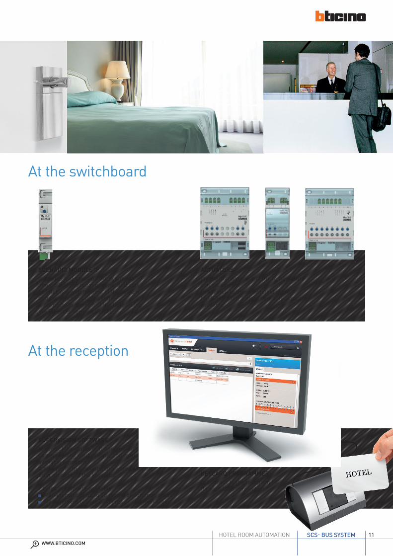
At the reception
At the switchboard
12
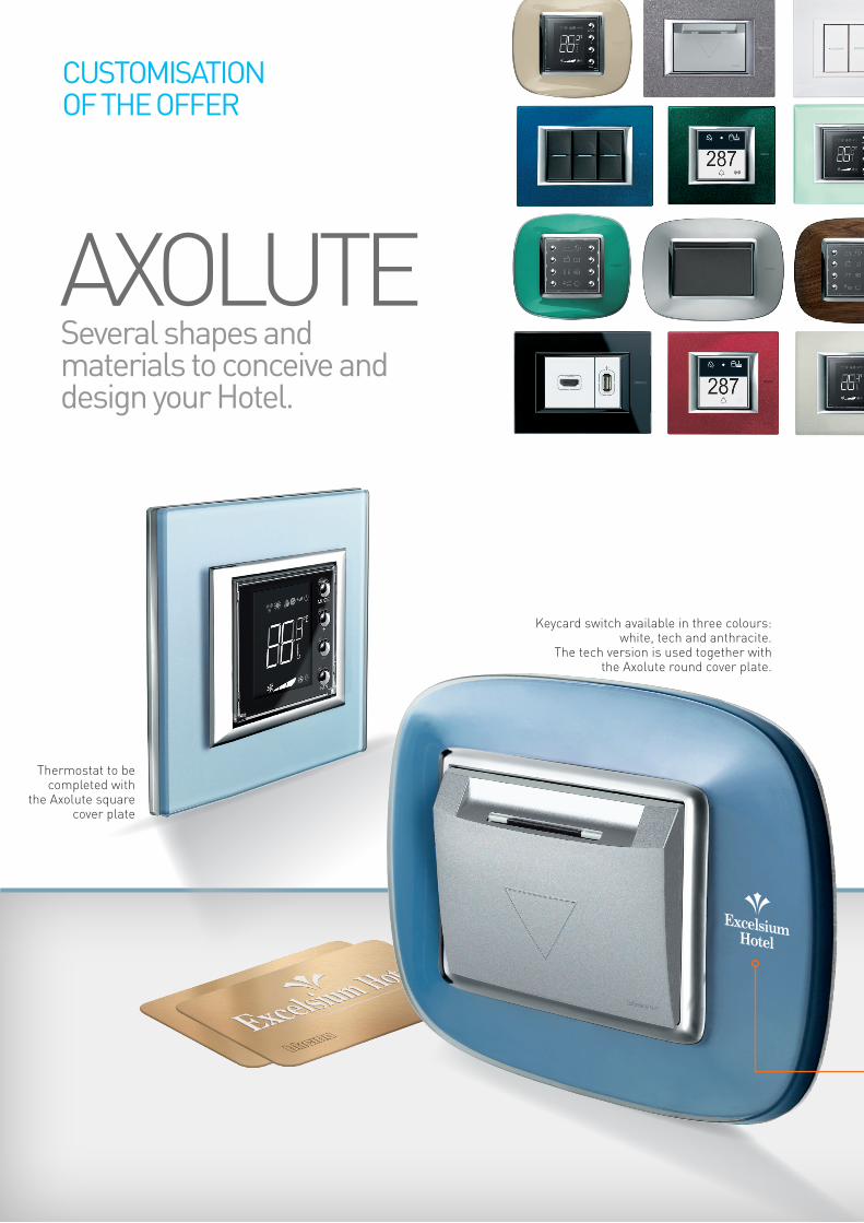
Thermostat to be completed with
the Axolute square cover plate
AXOLUTESeveral shapes and materials to conceive and design your Hotel.
CUSTOMISATION OF THE OFFER
Excelsium Hotel
Keycard switch available in three colours: white, tech and anthracite.
The tech version is used together with the Axolute round cover plate.

13WWW.BTICINO.COM
SCS- BUS SYSTEMHOTEL ROOM AUTOMATION
Countless finishes in the versions: Living International, Round, Square, Air.
LIVINGLIGHT
To further improve the aesthetic value of the offer, it is possible to customise both the cover plates and the keycards with the logo of the Hotel.
Tech keycard switch with Air cover plate.

14
INSIDE THE ROOM
Access control Climate control
(heating and cooling) Lighting control Automation management Wired and Wi-Fi network management
Traditional devices (energy sockets, etc...)
IN THE COMMON AREAS FOR CUSTOMERS CCTV Climate control
(heating and cooling) Lighting control Automation management Sound system Wi-Fi data network management Emergency lighting Traditional devices
(energy sockets, etc...)
From access control to home automation, BTicino offers all the
technological solutions for the hotel sector

15WWW.BTICINO.COM
SCS- BUS SYSTEMHOTEL ROOM AUTOMATION
A SOLUTION
FOR THE HOTELS
AT THE RECEPTION
THE SOFTWARE PROVIDES: Supervision and management of all the systems and functions installed in the hotel
Control and management of the functions inside the rooms and the common areas
Management of the room status (free, occupied, customer present)
Access control management: programming of keycards and saving of accesses
Management of bookings, also using specific software (PMS)
IN THE REST OF THE BUILDING
Energy transformation Energy distribution Service continuity (UPS) Energy management (measurement) VDI (video data) infrastructure Climate control (heating and cooling)
CCTV Access control Lighting control Automation management
Specific products and systemsfor the various areas GUEST ROOM AUTOMATION
SUPERVISION OF THE HOTEL FROM THE RECEPTION USING SPECIFIC SOFTWARE

16

17WWW.BTICINO.COM
SCS- BUS SYSTEMHOTEL ROOM AUTOMATION
18-23General rules
for installation
24-32Installation
and configuration
Contents
Maximum distances and absorptions 18Configuration 21”Hotelsupervision” supervision software 21Typical hotel system 22
Typical wiring diagram for common areas 24Variations of room diagrams 28

GENERAL RULES FOR INSTALLATION
18
In this chapter you will find all the details for correct installation of an SCS BUS system: SELV classification Maximum distances and
absorptions Maximum number of
configurable devices
For the purpose of the above calculations, refer to the TECHNICAL DATA found in the chapter TECHNICAL SHEETS.
In calculating the absorption it will be necessary to also consider the current available based on the length of the cable.
SELV classificationThe Automation system belongs to the SELV (Safety Extra Low Voltage) class, as it is powered with double safety insulation independent devices not connected to the ground, and has a maximum operating voltage of 27 Vdc, in accordance with CEI EN 60065; it therefore can be compared to a SELV source as described at point 411.125 of CEI 64-8-4. Compliance with SELV classification is only guaranteed subject to full compliance with current installation regulations, and with the general installation regulations for the individual devices and cables making up the system outlined by BTicino.
Maximum distances of the BUS cable and absorptionsThe maximum number of devices that can be connected to the BUS depends on the total absorption of the same and the distance between the point of connection and the power supply. The power supply can supply up to 1200 mA or 600 mA; the maximum number of devices that can be installed will therefore depend on the sum of their individual absorptions.
THE MAXIMUM LENGTH OF THE CONNECTIONS MUST NOT EXCEED 500 M (CABLE EXTENDED).
Device
Device
Length of connection to the furthest device
Connections
Junction box
Junction box
Power supply
Power supply
THE CONNECTION LENGTH BETWEEN THE POWER SUPPLY AND THE FURTHEST DEVICE MUST NOT EXCEED 250M.
1
2
During sizing comply with the following rules:
MAXIMUM DISTANCES AND ABSORPTIONS

19WWW.BTICINO.COM
SCS- BUS SYSTEMHOTEL ROOM AUTOMATION
4321
C1 C2
1
C3 C4
55432
ON
OFF
E46ADCN
PRI
E49PRI: 220 – 240 V~
185 – 175 mA
50/60 Hz
SCS: 27 Vdc
600 mA
SCS
4321
C1 C2
1
C3 C4
55432
ON
OFF
E49
A A
B B
FOR OPTIMUM DIVISION OF THE CURRENTS ON THE BUS LINE IT IS RECOMMENDED THAT THE POWER SUPPLY IS INSTALLED IN AN INTERMEDIATE POSITION.
NOTE: If a UTP5 cable is used in alternative to the L4669 BUS cable, distances are halved.
With power supply E46ADCN:
A = 250 m maxB = 250 m maxA + B = 500 m
Maximum current provided by the power supply: 1200 mA.
With power supply E49:
A = 250 m maxB = 250 m maxA + B = 500 m
Maximum current provided by the power supply: 600 mA.
3
FOR MORE INFORMATION ON THE DESIGN AND INSTALLATION OF THE SCS-BUS SOLUTIONS SEE THE SPECIFIC MyHOME TECHNICAL GUIDEhttp://www.pageflip.bticino.it/myhomegb/
automation
DESIGN ANDINSTALLATION
GUIDE

GENERAL RULES FOR INSTALLATION
20
Maximum distances for the connection of actuators based on the loadIn order to correctly manage certain types of loads, it is necessary to comply with some installation requirements, applicable to all the actuators used.Fluorescent lamps: The length of the connection cable between the actuator and the load must not be less than 3 m. Do not connect more than 15 actuators controlling this type of lamps to the same line.Metal halide and sodium vapour lamps: in addition to the indications provided for fluorescent lamps, also pay attention to the instructions for use for these lamps (for example avoid switching on when hot), do not connect dimmers to the same line of these lamps, keep the BUS line
C1
1 2 3
F411/1N
1 2 L N
N
L
3
PL1 CPL2
SPE
M
PL2
A
PL1
BUS
Bathroom pull-cord pushbutton
MAXIMUM DISTANCES FOR THE CONNECTION OF THE CONTACT INTERFACE
MAX 50 m
MIN 3 m
WARNING: refer to the technical data listed in the technical sheets for each actuator
Maximum distance for the connection of the contact interfaceThe length of the connection between the interface (basic or in DIN module) and the traditional type device must not exceed 50 m. Several pushbuttons may be connected to the interface inputs.
MAXIMUM DISTANCES AND ABSORPTIONS
and the power line for these types of lamps separated by at least one metre. Three-phase networks: In case of three-phase networks, check the
balancing of the phases, and the quality of the network. Failure to comply with the above requirements can compromise the correct operation of the devices.
EXAMPLE OF CONNECTION WITH ITEM F411/1N

21WWW.BTICINO.COM
SCS- BUS SYSTEMHOTEL ROOM AUTOMATION
The HotelSupervision software has been purposely designed for the management and the supervision of hotels. All the management operations can be performed from one single location, typically the Reception desk, from where it is possible to have a complete view of what happens in the individual rooms and the common areas.
Some functions: Temperature management with direct control of thermostats, but giving guests the possibility of adjusting the temperature within the set limits.
Keycard management, with the possibility of limiting access to certain areas of the hotel and monitoring of movements using each key card.
Management of alarm clocks and messages for guests; an audible signal notifies operators of an alarm clock request, so that they can act accordingly within the required time scales.
Control of different types of alerts from rooms or common areas.
Control of DND or MUR type notifications; check of presence inside the room.
The use of different icons and colours helps the operator to immediately identify the status of the room.
The configuration of SCS-BUS technology devices can be completed in two different ways:
Physical configurationThis is completed using the green and blue configurators, which must be connected to the appropriate housings found on the devices.
Software configuration This is performed using a PC with the appropriate MyHOME_Suite application installed. This solution has the advantage of offering many more options when compared with the physical configuration.
The software can be downloaded free of charge from the website:www.homesystems-legrandgroup.com
CONFIGURATION
”HOTELSUPERVISION” SUPERVISION SOFTWARE
PHYSICAL CONFIGURATION
SOFTWARE CONFIGURATION Download the software for free (QR code)
Download the desired version of
the HotelSupervision software (QR code)
Both HotelSupervision software programs can be downloaded from the website: www.homesystems-legrandgroup.com/BtHomeSystems/productDetail.action?productId=003
The software is available in two versions:
(3544SW) Management and supervision of up to 20 rooms or common areas
(3546SW) Management and supervision of over 20 rooms or common areas

INSTALLATION AND CONFIGURATION
22
OTHER FLOORS
ZONE 9
ZONE 6
ZONE 3
ZONE 1
Room 301
Room 201
Room 101
Reception
ZONE 10
ZONE 7
ZONE 4
Corridor
Corridor
Corridor
ZONE 11
ZONE 8
ZONE 5
Room 302
Room 202
Room 102
ZONE 2Bar
TYPICAL HOTEL SYSTEM
2nd
1st
T
3rdFLOOR
FLOOR
FLOOR
FLOOR

23WWW.BTICINO.COM
SCS- BUS SYSTEMHOTEL ROOM AUTOMATION
2 3 4 5 61
DC - In
2 3 4 5 61
DC - In
MODE
+
–
FAN
DND MUR
MH201
MH201
BUS SCS 3
H4651LN4651
H4648 LN4648
H4653LN4653
H4652 LN4652
H4691LN4691
ROOM 301
HUB Switch
To the other rooms
To the floor services
MODE
+
–
FAN
DND MUR
MH201
348210
348402
MH201
BUS SCS 1
101H4651LN4651
H4648 LN4648
H4653LN4653
H4652 LN4652
H4691LN4691
TO THE OTHER FLOORS
ROOM 101
HUB Switch
PC + software for room management
Card programming
USB cable
Existing hotel Ethernet network
2 3 4 5 61
DC - In
MODE
+
–
FAN
DND MUR
MH201
MH201230 Vac
E49
BUS SCS 2
201H4651LN4651
H4648 LN4648
H4653LN4653
H4652 LN4652
H4691LN4691
ROOM 201
HUB SwitchSCS
E49PRI: 220 – 240 V~ 185 – 175 mA 50/60 HzSCS: 27 Vdc 600 mA
230 Vac
E49
SCS
E49PRI: 220 – 240 V~ 185 – 175 mA 50/60 HzSCS: 27 Vdc 600 mA
230 Vac
E49
SCS
E49PRI: 220 – 240 V~ 185 – 175 mA 50/60 HzSCS: 27 Vdc 600 mA
301
To the floor services
To the floor services
To the other rooms
To the other rooms
Below is a description and presentation of a typical application of the SCS-BUS solution in a welcoming structure.
For each room or zone to control, manage, and supervise, an MH201 IP Scenario Module must be installed. The zones can be: reception, hall, corridor, restaurants, bar, lounge area,...
In installation including more than 100 rooms and zones, only one F458 Server IP device must be connected to the data network.
Typical block system with rooms and common areas

INSTALLATION AND CONFIGURATION
24
These pages show a typical electric diagram that can be used to install a system in a hotel or welcoming establishment.
The diagram consists of two parts:- in the first part is a wiring diagram for the common areas.- in the second part is the complete diagram inside the room.
Inside the room are the following functions: Courtesy light Entrance door open control Refrigerator door open control Safe open control Bathroom alarm Entrance door bell Entrance door electric door lock control Air conditioning system Eco function
IMPORTANT NOTESThe general switch GS (TM+EL) must be selected based on the absorption of the services installed.The TM switch must be selected based on the power supply used.
The TM switch must be selected based on the loads connected.If the current supplied by the E49 is not sufficient to power the SCS system, it is possible to use the E46ADCN power supply.The actuator to be used depends on the type of air conditioning system installed.In alternative, it is also possible to only use one actuator with 4 conduits (F411/4) instead of the two: F411/2 and F411/1N.Only use the most suitable sensor for the mechanical application. See the specific catalogue.The devices to carry out the required functions must be configured using the MyHOME_Suite software.The room identification number must be saved in the MH201 during the configuration.It is possible to connect the system configuration PC at any point of the data network, and to use the PC at reception to configure and maintain the system.
ITEM DESCRIPTIONE49 Power supplyLN4651 Keycard reader outside the door and indicatorsLN4648 Transponder keycard switchLN4653 DND and MUR controlLN4652 8 key scenario controlLN4691 Thermostat with displayMH201 Scenario module IPF430R8 Air conditioning actuatorF411/1N DIN module 1 relay actuatorF411/2 DIN module 2 relay actuatorF428 DIN module contact interface 3476 Basic control actuatorFT1A2N230 Room remote switch3511 Magnetic sensors
AB
D
GHILMN
C E F
TYPICAL WIRING DIAGRAM FOR COMMON AREAS AND HOTEL ROOM NO. 127PROJECT DESCRIPTION
LEGEND
NOTES
The devices listed in the legend refer to the LivingLight series; for all the other ranges refer to the catalogue section.

25WWW.BTICINO.COM
SCS- BUS SYSTEMHOTEL ROOM AUTOMATION
1ST FLOOR - CORRIDOR
RECEPTION
2 3 4 5 61
DC - In
2 3 4 5 61
DC - In
To the Technical
room, data network VDI
board (BTNET)
PC for the system configuration
Corridor Wi-Fi access point
HUB Switch
Room 127Room 129
To the other floors
PC + software for the room automation
348402
348210
Existing hotel Ethernet network
Room 128
To the room 127 socket
HUB Switch
N
CONT.
2ND FLOOR - CORRIDOR

INSTALLATION AND CONFIGURATION
26
TYPICAL WIRING DIAGRAM FOR A HOTEL ROOM NO. 127
FCB
A
D
H
ADDITIONAL FUNCTIONS INSIDE THE ROOM Courtesy light Entrance door open control Refrigerator door open control Safe open control Bathroom alarm Entrance door bell Entrance door electric door lock control ECO function
BACK
A = 1PL = 1M = PUL
A = 9PL = 8M = CENLED = –
A = 9PL = 9M1 = CENDEL1 = –M2 = –DEL2 = –
R1 = 0R2 = 1M = –
R1 = 0R2 = 1
M = 2 L = – A = 1 PL = 1 T = 2
1ST FLOOR - ROOM 127
DND MUR
C1
1 2 3
F411/1N
SCS
E49PRI: 220 – 240 V~
185 – 175 mA
50/60 Hz
SCS: 27 Vdc
600 mA
230 V50 Hz
L
N
IG(MGT+earth leak.)
MH201 MGT2 MGT1
Light and socket power always on
E49Data network inside the room
230 Vac
Bell12-24 Vac/dc max 1 A
Transformer Transformer
LN4651
F411/1N
Room door electric lock LN4653 LN4652 LN4648
MGT4
From HUB Switch 1st floor
From HUB Switch 1st floor
MH201

27WWW.BTICINO.COM
SCS- BUS SYSTEMHOTEL ROOM AUTOMATION
C1 C2
ART. F430/2
1
1 2 3 4
2 43
M
C
N1 N2
N1 N2
F428
C
N1 N2
N1 N2
F428 21
ART. 3476230V ˜2A cos �= 0,62A
L L1
MGT3
Light and socket power activated by the presence inside the room
1 3 A1
A22 4
Room remote switch
Courtesy light
Magnetic safe sensor
Refrigerator door open magnetic sensor
S2 S3 S1
P1Courtesy light
F428F411/2
3476
F428
Bathroom call confirmation buzzer
ON
ECOwindow open
window closed
3511
Magnetic window sensor
OUT 3OUT 2OUT 1OUT 5OUT 4
OUT 3OUT 2OUT 1
NOUT 5OUT 4
L1 L2
N L
230 Vac
F430R8
LN4691
BUS/SCS
L
N
Magnetic door sensor
P2
Bathroom pull-cord pushbutton
FT1A2N230230 Vac – 25 Max
To other devices
MODE
+
–
FAN
ZA = –ZB = 1N = 1LAOD = –
G
A = 1PL = 4M = PULG = –
A = –PL1 = –PL2 = –M = –SPE = –
A = –PL1 = –PL2 = –M = –SPE = –
A = 1PL1 = 2PL2 = 3G = –M = –
I
II
H L L
E
I
ZA = –ZB = 1
TYPE = 1HEAT = 7COOL = CENPUMP = –IN = 3

INSTALLATION AND CONFIGURATION
28
N
L
ON
OFF
ON
OFF
ON
OFF
ON
OFF
ON
GEN
OFF
L4671/1 L4671/1
BUSBUS
L4652/2L4652/2
E46ADCN
230 Vac
230 Vac
L1 L2A = 1PL = 1M = O/IG1 = –G2 = –
A = 1PL = 2M = O/IG1 = –G2 = –
A = GENPL1 = –M = O/I
A = 1PL1 = 1M1 = O/IA2 = 1PL2 = 2M = O/I
N
L
ON
OFF
11
ART. 3475230V ˜2A cos �= 0,62A
L L1
E46ADCN3475
BUS230 Vac
L4659N
230 Vac
L4652/2
A = 1PL = 1M = –G = –
A = 1PL = 1M = –S = 1T = 4
A1 = 1PL1 = 1M1 = O/I
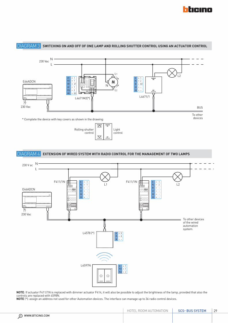
The device controls the load with the address indicated in A and PL. When a presence is detected, if the light level is lower than the set level, the device switches the allocated load, keeping it on for the time set with the configurator connected to T. The sensitivity of the PIR movement sensor is set using the configurator connected to S. For correct operation, the sensor’s lighting Set Point must be set (see procedure). When a user switches the light off manually using a control, the movement sensor is disabled, and no presence is detected for a period of time indicated by T.
DIAGRAM 2 AUTOMATIC SWITCHING ON OF THE LIGHT USING A PASSIVE INFRARED SENSOR
To other devices
To other devices
DIAGRAM 1 SWITCHING ON AND OFF OF 2 LAMPS FROM 4 LIGHT POINTS WITH GENERAL ON/OFF COMMAND
For other functions
VARIATIONS OF ROOM DIAGRAMS
Below are some typical diagrams that may be useful for the integration of the functionalities inside the room. The configuration in the examples refers to the individual diagram.
29WWW.BTICINO.COM
SCS- BUS SYSTEMHOTEL ROOM AUTOMATION
M
N
L
ON
OFF
N
L1
L2
BUS
E46ADCN
L4671M2(*) L4671/1
230 Vac
A1 = 1PL1 = 1M1 = (A2 = 1PL2 = 2M2 = O/I
A = 1PL = 2M = O/IG1 = –G2 = –
230 Vac
L2
ON
OFF
C1
1 2 3
F411/1N
C1
1 2 3
F411/1N
N
L
F411/1N
L4578 (*)
L4597N
230 Vac
F411/1N
230 V ac
L1 L2
A = 9PL = 8M = –
E46ADCN
A = 1PL = 1M = –G1 = –G2 = –G3 = –
A = 1PL = 2M = –G1 = –G2 = –G3 = –
A = 1PL1 = 1PL2 = 2
DIAGRAM 4 EXTENSION OF WIRED SYSTEM WITH RADIO CONTROL FOR THE MANAGEMENT OF TWO LAMPS
DIAGRAM 3 SWITCHING ON AND OFF OF ONE LAMP AND ROLLING SHUTTER CONTROL USING AN ACTUATOR CONTROL
* Complete the device with key covers as shown in the drawing:
Rolling shutter control
Light control
To other devices of the wired automation system
NOTE: If actuator F411/1N is replaced with dimmer actuator F414, it will also be possible to adjust the brightness of the lamp, provided that also the controls are replaced with 4598N.NOTE (*): assign an address not used for other Automation devices. The interface can manage up to 36 radio control devices.
To other devices
INSTALLATION AND CONFIGURATION
30
C1
ART. F413N
2+-
0-10V
1 NC 43
L
+
N L - +
ON
OFF
BUS
L4652/2
F413N
E46ADCN
230 Vac
230 VacN
LN
L
A PL M G
-���
T5
H 2
50
V
230V~
�������
50Hz 60 1000VA¤
N
L
ON
OFF
BUS
L4652/2
E46ADCN
230 Vac
230 Vac
A1 = 1PL1 = 2M1 = O/I
A = 1PL = 2M = –G = –
Ballast
To other devices
For other functions
To other devices
F414DIN
dimmer actuator
Filament, halogen, and ferromagnetic transformer lamps
For other functions
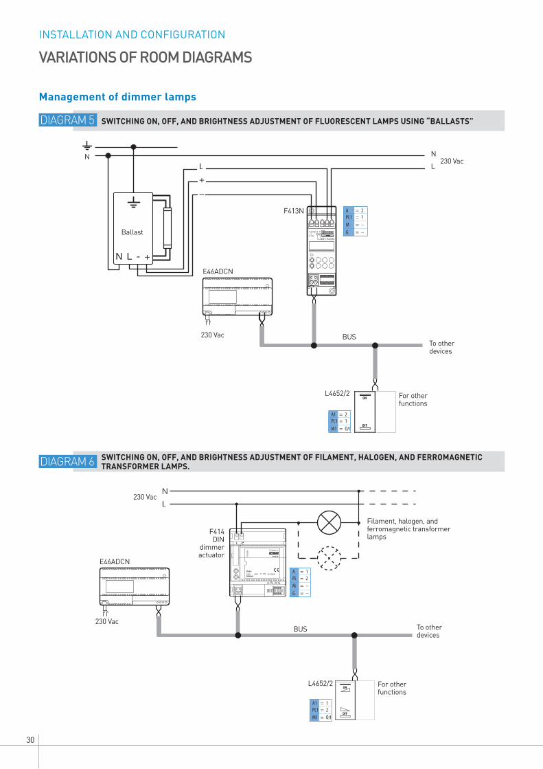
VARIATIONS OF ROOM DIAGRAMS
Management of dimmer lamps
DIAGRAM 5 SWITCHING ON, OFF, AND BRIGHTNESS ADJUSTMENT OF FLUORESCENT LAMPS USING “BALLASTS”
DIAGRAM 6 SWITCHING ON, OFF, AND BRIGHTNESS ADJUSTMENT OF FILAMENT, HALOGEN, AND FERROMAGNETIC TRANSFORMER LAMPS.
A = 2PL1 = 1M = –G = –
A1 = 2PL1 = 1M1 = O/I
31WWW.BTICINO.COM
SCS- BUS SYSTEMHOTEL ROOM AUTOMATION
C1 C2 C3 C4
ART. F411/4
1 2 4 53E46ADCN
230 Vac
L4652/2
M2˜
Ap C ChNL
Ap C Ch230 Vac
F411/4
BUS
M1˜
A = 2PL = 1M = (
A = 2PL1 = 1PL2 = 1PL3 = 1PL4 = 1M = 1
C1 C2
ART. F411/2
1 2 43
N
L
M1
N
L1 L2
C1 C2
ART. F411/2
1 2 43
M2
N
L1 L2
C1 C2
ART. F411/2
1 2 43
M3
N
L1 L2
GEN
E46ADCN
230 Vac
F411/2
L4652/2
BUS
230 Vac
A = GENPL = –M = (
A = 2PL1 = 1PL2 = 1G = –M = –
A = 2PL1 = 1A2 = 2PL2 = 2A3 = 2PL3 = 3M = (
L4652/3
F411/2 A = 2PL1 = 2PL2 = 2G = –M = –
F411/2 A = 2PL1 = 3PL2 = 3G = –M = –
To other devices
For other functions
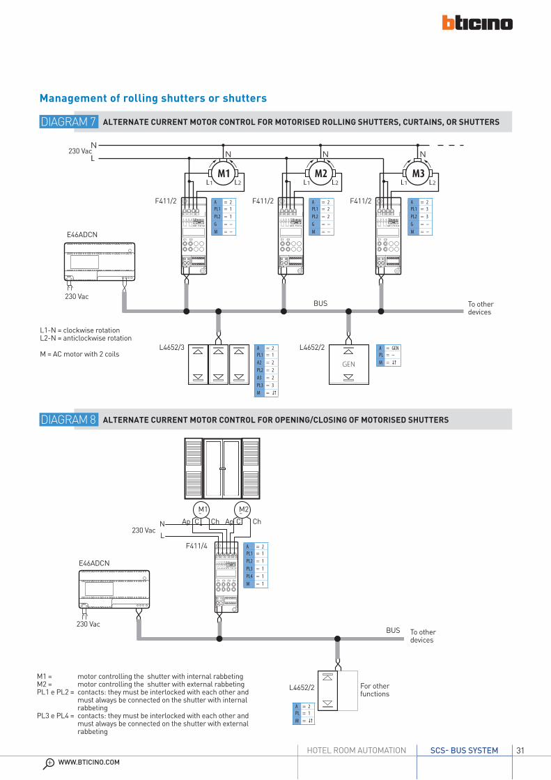
M1 = motor controlling the shutter with internal rabbetingM2 = motor controlling the shutter with external rabbetingPL1 e PL2 = contacts: they must be interlocked with each other and
must always be connected on the shutter with internal rabbeting
PL3 e PL4 = contacts: they must be interlocked with each other and must always be connected on the shutter with external rabbeting
To other devices
L1-N = clockwise rotationL2-N = anticlockwise rotation
M = AC motor with 2 coils
Management of rolling shutters or shutters
DIAGRAM 7 ALTERNATE CURRENT MOTOR CONTROL FOR MOTORISED ROLLING SHUTTERS, CURTAINS, OR SHUTTERS
DIAGRAM 8 ALTERNATE CURRENT MOTOR CONTROL FOR OPENING/CLOSING OF MOTORISED SHUTTERS

INSTALLATION AND CONFIGURATION
32
N
L
M
ON
OFF
&�
� � �
F411/1N
&�
� � �
F411/1N
E46ADCN
F411/1N F411/1N
230 Vac
230 Vac
BUS
L4652/2
A = 3PL = 1M = 2G1 = –G2 = –G3 = –
A = 3PL = 1M = SLAG1 = –G2 = –G3 = –
A = 3PL = 1M = O/I
E46ADCN
F411/2
L4652/2
230 Vac
230 Vac
BUS
C1 C2
ART. F411/2
1 2 43
C1 C2
ART. F411/2
1 2 43
24 Vdc M
++
The ON control activates the light and the extractor fan at the same time.The OFF control switches the light off, while the extractor fan goes off after 2 minutes (configurator in M=2 of the Master actuator)
To other devices
Bathroom light
Bathroom fan
Power supply B
To other devices
For other functionsIt is possible to use direct current motors with other characteristics
(12 - 24 - 48 Vdc), by replacing the power supply with one compatible with the motor features (voltage and current), and checking the absorptions of the motor against the capacity of the relays of the actuators (F411/2).
VARIATIONS OF ROOM DIAGRAMS
Management of different loads
DIAGRAM 9 BATHROOM LIGHT AND EXTRACTOR FAN ON CONTROL WITH DELAYED SWITCHING OFF
DIAGRAM 10 DIRECT CURRENT MOTOR CONTROL FOR MOTORISED CURTAINS (E.G. 24 VDC)
F411/2A = 3PL1 = 1PL2 = 1G = –M = –
A = 3PL1 = 1PL2 = 1G = –M = SLA
A = 3PL = 1M = (

33WWW.BTICINO.COM
SCS- BUS SYSTEMHOTEL ROOM AUTOMATION
34-45Catalogue
46-81Technical
sheets
Contents
AXOLUTE + Dimensional data 34LIVINGLIGHT + Dimensional data 40
Technical sheets 46

CATALOGUE
34
The BTicino offer for the rooms, and in wider terms for the whole hotel establishment, includes many more devices that are normally also used for other applications.
Request or view the Axolute catalogue
STANDARD EQUIPMENT
EQUIPMENT INCLUDING SPECIFIC PRODUCTS FOR THE SCS-BUS ROOM
A complete offer for a state of the art electric system inside the whole welcoming establishment and in particular inside the hotel room. All this to ensure that customers feel immediately at ease. The offer includes both standard traditional functions, and more advanced functions.
AXOLUTEsolutions
hotel
DESIGNED TO IMPROVE THE COMFORT OF THE CUSTOMERA solution for all kinds of hotels
CATALOGUE

35WWW.BTICINO.COM
SCS- BUS SYSTEMHOTEL ROOM AUTOMATION
AXOLUTE - CATALOGUESCS-BUS devices
H4652 H4691
H4651
F430R8 F430R3V10 F430V10 MH201
H4650
H4653
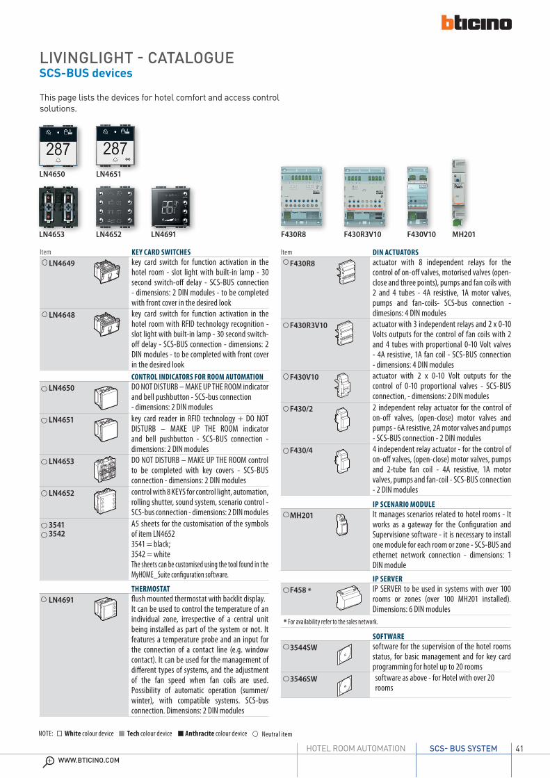
CONTROL INDICATORS FOR ROOM AUTOMATIONH4650 DO NOT DISTURB – MAKE UP THE ROOM indicator
and bell pushbutton - SCS-bus connection - dimensions: 2 DIN modules
H4651 key card reader in RFID technology + DO NOT DISTURB – MAKE UP THE ROOM indicator and bell pushbutton - SCS-BUS connection - dimensions: 2 DIN modules
H4653 DO NOT DISTURB – MAKE UP THE ROOM control to be completed with key covers - SCS-BUS connection - dimensions: 2 DIN modules
H4652 control with 8 KEYS for control light, automation, rolling shutter, sound system, scenario control - SCS-bus connection - dimensions: 2 DIN modules
35413542
A5 sheets for the customisation of the symbols of item LN46523541 = black; 3542 = whiteThe sheets can be customised using the tool found in the MyHOME_Suite configuration software.
Item KEY CARD SWITCHESH4649 key card switch for function activation in the
hotel room - slot light with built-in lamp - 30 second switch-off delay - SCS-BUS connection - dimensions: 2 DIN modules - to be completed with front cover in the desired look
H4648 key card switch for function activation in the hotel room with RFID technology recognition - slot light with built-in lamp - 30 second switch-off delay - SCS-BUS connection - dimensions: 2 DIN modules - to be completed with front cover in the desired look
IP SCENARI0 MODULEMH201 It manages scenarios related to hotel rooms - It
works as a gateway for the Configuration and Supervisione software - it is necessary to install one module for each room or zone - SCS-BUS and ethernet network connection - dimensions: 1 DIN moduleIP SERVER
F458 * IP SERVER to be used in systems with over 100 rooms or zones (over 100 MH201 installed). Dimensions: 6 DIN modules
* For availability refer to the sales network.
Item DIN ACTUATORSF430R8 actuator with 8 independent relays for the
control of on-off valves, motorised valves (open-close and three points), pumps and fan coils with 2 and 4 tubes - 4A resistive, 1A motor valves, pumps and fan-coils- SCS-bus connection - dimesions: 4 DIN modules
F430R3V10 actuator with 3 independent relays and 2 x 0-10 Volts outputs for the control of fan coils with 2 and 4 tubes with proportional 0-10 Volt valves - 4A resistive, 1A fan coil - SCS-BUS connection - dimensions: 4 DIN modules
F430V10 actuator with 2 x 0-10 Volt outputs for the control of 0-10 proportional valves - SCS-BUS connection, - dimensions: 2 DIN modules
F430/2 2 independent relay actuator for the control of on-off valves, (open-close) motor valves and pumps - 6A resistive, 2A motor valves and pumps - SCS-BUS connection - 2 DIN modules
F430/4 4 independent relay actuator - for the control of on-off valves, (open-close) motor valves, pumps and 2-tube fan coil - 4A resistive, 1A motor valves, pumps and fan-coil - SCS-BUS connection - 2 DIN modules
SOFTWARE3544SW software for the supervision of the hotel rooms
status, for basic management and for key card programming for hotel up to 20 rooms
3546SW software as above - for Hotel with over 20 rooms
THERMOSTATH4691 flush mounted thermostat with backlit display.
It can be used to control the temperature of an individual zone, irrespective of a central unit being installed as part of the system or not. It features a temperature probe and an input for the connection of a contact line (e.g. window contact). It can be used for the management of different types of systems, and the adjustment of the fan speed when fan coils are used. Possibility of automatic operation (summer/winter), with compatible systems. SCS-bus connection. Dimensions: 2 DIN modules
This page lists the devices for hotel comfort and access control solutions.
White colour deviceNOTE: Neutral itemTech colour device Anthracite colour device

CATALOGUE
36
AXOLUTE - CATALOGUEDevices and accessories for SCS-BUS
E46ADCN
POWER SUPPLIESE46ADCN power supply - input 230 Vac, output 27 Vdc SELV
– maximum consumption 450 mA – maximum output current: 1.2 A - DIN rail mounted model - space requirement 8 DIN modules – for flush mounted or wall mounted switchboards
E49 compact power supply - input 230 Vac, output 27 Vdc - maximum power delivered 600 mA - dimensions: 2 DIN modules
Item VARIOUS ACCESSORIES3515 spare plug-in clamps
Item KEY CARDS AND KEY CARD PROGRAMMER348210 Credit card keycard (ISO 50x80 mm). It uses
transponder technology with frequency: 13.56 MHz. To be used together with the keycard programmer, item code 348402. The keycard can be customised and is sold in lots of 5 pieces.
348402 Table-top key card programmer to be connected to the PC in the reception.
348402 3515
CONTACT INTERFACE3477 basic module control interface with 2
independent contacts for the control of 2 actuators for single function loads, or 1 actuator for double function loads (shutters) – the inputs accepts two traditional switches or pushbuttons with NO and NC contact, or a traditional two-way switch, or interlocked pushbuttons
F428 basic module control interface with 2 independent contacts for the control of 2 actuators for single function loads, or 1 actuator for double function loads (shutters) – the inputs accepts two traditional switches or pushbuttons with NO and NC contact, or a traditional two-way switch, or interlocked pushbuttons - 2 DIN modules
CONTACT INTERFACE WITH ACTUATOR3476 1 relay actuator - for single loads: 2 A resistive
or incandescence lamps and 2 A cosϕ 0.5 for ferromagnetic transformers – input suitable for a traditional NO contact pushbutton
MAGNETIC CONTACTS3510 NC electromagnetic contact interface detectors
and protection line - flush mounted version3510M NC electromagnetic contact interface detectors
and protection line – made of brass with high mechanical resistance, for installation in non ferromagnetic material windows and doors, or in low section doors and windows
3510PB NC electromagnetic contact interface detectors and protection line – made of brass, with high mechanical resistance for installation in all types of doors and windows and reinforced doors
3511 NC electromagnetic contact interface detectors and protection line - visible mounted version
3512 NC electromagnetic contact interface detectors and protection line – made of die cast aluminium, for installation on tilting or sliding doors. Preset for floor installation
3513 NC electromagnetic contact interface detectors and protection line - version for visible installation on metal surfaces
3480 F482 3510M 3511 3512
White colour deviceNOTE: Neutral itemTech colour device Anthracite colour device

37WWW.BTICINO.COM
SCS- BUS SYSTEMHOTEL ROOM AUTOMATION
AXOLUTE - CATALOGUEDevices and accessories for SCS-BUS
Item CONFIGURATOR KIT3501K kit of configurators from 0 to 9
3501K/1 kit of configurators AUX, GEN, GR, AMB,ON, OFF, O/I, PUL, SLA, CEN, , M
CONFIGURATORS – SINGLE-TYPE PACKAGE OF 10 PIECES
3501/PUL configurator PUL3501/SLA configurator SLA3501/CEN configurator CEN3501/T configurator3501/TM configurator M
ItemCONFIGURATORS – SINGLE-TYPE PACKAGE OF10 PIECES
3501/0 configurator 03501/1 configurator 13501/2 configurator 23501/3 configurator 33501/4 configurator 43501/5 configurator 53501/6 configurator 63501/7 configurator 73501/8 configurator 83501/9 configurator 93501/GEN configurator GEN3501/GR configurator GR3501/AMB configurator AMB3501/AUX configurator AUX3501/ON configurator ON3501/OFF configurator OFF3501/OI configurator OI
¬
¬
¬
¬
3501/1 3501/2 3501/3 3501/4
3501/GEN 3501/GR 3501/AMB 3501/AUX
3501/0
3501/PUL 3501/SLA 3501/CEN 3501/T
¬
¬
¬
¬
CONNECTION CABLESL4669 sheathed pair made up of 2 flexible wires with
unshielded plaited sheath - insulation 300/500 V - complies with standards CEI 46-5 and CEI 20-20 - coil length 100 metres
L4669/500 as above - coil length 500 metres
L4669KM1 as above - reel lenght 1000 metres
336904 specific cable with 2 twisted conductors. It can be installed in underground piping, in accordance with CEI 20-13 and CEI 20-14 standards. - coil length 200 metres
L4669HF as above - low toxicity cable without halogens - ideal for application in environments where fire hazard safety is critical - coil length 200 metres
L4669L4669/500
336904L4669HF
3501K/1
FOR MORE INFORMATION ON THE DESIGN AND INSTALLATION OF THE SCS-BUS SOLUTIONS REFER TO THE SPECIFIC MYHOME TECHNICAL GUIDE http://www.pageflip.bticino.it/myhomegb/
White colour deviceNOTE: Neutral itemTech colour device Anthracite colour device
automation
DESIGN ANDINSTALLATION
GUIDE

CATALOGUE
38
LAMPHOLDER FOR OFF-DOOR SIGNALLINGH4372V230H off-door lampholder with double optical
signalling: do not disturb and make up room – use 2 LEDs item LN4742V12T (12V)
H4549
USB CHARGERHD4285C HC4285CHS4285C
5 Vdc USB socket for charging electronic devices up to 750 mA like mobile phones, smartphones, tablets and similar – 230 Vac power supply
HD4285C2 HC4285C2HS4285C2
5 Vdc USB socket for quick charge of one single electronic device (mobile phones, smartphones, tablets or similar) up to 1.550 mA or simultaneous charging of two devices up to 750 mA – 230 Vac power supply
HC4033HD4177
H4372V230H
HD4285C2
AXOLUTE - CATALOGUETraditional devices
KEY COVERS WITH SYMBOLS FOR SCS CONTROLHD4915DDHC4915DD HS4915DD
key cover with ”do not disturb” symbol
HD4915M2DDHC4915M2DD HS4915M2DD
key cover with ”do not disturb” symbol -2 modules
HD4915MRHC4915MRHS4915MR
key cover with ”make up room” symbol
HD4915BLHC4915BL HS4915BL
key cover with ”room light” symbol
HD4915M2BLHC4915M2BL HS4915M2BL
key cover with ”room light” symbol - 2 modules
KEY COVER WITH SYMBOLS FOR AXIAL CONTROLSHD4921BLHC4921BLHS4921BL
key cover with bed light symbol
HD4921M2BLHC4921M2BLHS4921M2BL
key cover with bed light symbol - 2 modules
HD4921DDHC4921DDHS4921DD
key cover with do not disturb symbol
HD4921MRHC4921MRHS4921MR
key cover with make up room symbol
HS4547 HC4915DD HC4915MR
Finishing accessories for SCS and traditional devices
Item KEY CARD SWITCHH4549 key card switch for the power supply inside the
hotel room - slot light with built-in lamp - 30 second switch-off delay - power supply 230 Va.c. - 2 modules - to be completed with front cover in the desired look
H4548 key card switch for the power supply inside the hotel room with RFID technology recognition - slot light with built-in lamp - 30 second switch-off delay - power supply 230 Va.c. - 2 modules - to be completed with front cover in the desired look
CORD PUSHBUTTONSHD4033HC4033 HS4033
cord pushbutton 1 P NO 10 A for bathroom alarm
SHAVER SOCKETSHD4177HC4177 HS4177
shaver socket with insulation transformer - input voltage 230 Vac @ 50/60 Hz - output voltage 115/230 Vac 20 VA
Item FRONT COVERS FOR KEY CARD SWITCHESHD4547HC4547 HS4547
front cover for traditonal or SCS key card switch - 2 modules
White colour deviceNOTE: Neutral itemTech colour device Anthracite colour device

39WWW.BTICINO.COM
SCS- BUS SYSTEMHOTEL ROOM AUTOMATION
126
93
149
9393
103
RECTANGULAR COVER PLATES
ELLIPTIC COVER PLATES
HA4802...
HA4826...HA4806...
HB4806...
HB4802... HB4803... HB4804...
HB4826...
127
95
127
141,5
195
95
195
93
126
138,5
150
9595
104
MODULAR DEVICES
2 modules1 module 3 modules
22,5
45
45
45
67,5
45
HA4804...HA4803...
AXOLUTE - CATALOGUEDimensional data
DIN DEVICES
DIN DIMENSION TABLE (mm) No. of Mod. A B C1 17.5 82 662 35 82 663 52.5 82 664 70 82 665 87.5 82 666 105 82 667 122.5 82 668 140 82 669 157.5 82 6610 175 82 6612 210 82 66
A C
B
2 DIN modules
3480
BASE INTERFACE MODULE
40 18
40

CATALOGUE
40
A complete offer for a state of the art electric system inside the whole welcoming establishment and in particular inside the hotel room. All this to ensure that customers feel immediately at ease. The offer includes both standard traditional functions, and more advanced functions.
LIVINGLIGHT
DESIGNED TO IMPROVE THE COMFORT OF THE CUSTOMERA solution for all kinds of hotels
STANDARD EQUIPMENT
EQUIPMENT INCLUDING SPECIFIC PRODUCTS FOR THE SCS-BUS ROOM
solutionshotel
The BTicino offer for the rooms, and in wider terms for the whole hotel establishment, includes many more devices that are normally also used for other applications.
Request or view the Livinglight catalogue
LIVINGLIGHTONE FOR ALL,
ALL FOUR YOU
41WWW.BTICINO.COM
SCS- BUS SYSTEMHOTEL ROOM AUTOMATION
LIVINGLIGHT - CATALOGUESCS-BUS devices
CONTROL INDICATORS FOR ROOM AUTOMATIONLN4650 DO NOT DISTURB – MAKE UP THE ROOM indicator
and bell pushbutton - SCS-bus connection - dimensions: 2 DIN modules
LN4651 key card reader in RFID technology + DO NOT DISTURB – MAKE UP THE ROOM indicator and bell pushbutton - SCS-BUS connection - dimensions: 2 DIN modules
LN4653 DO NOT DISTURB – MAKE UP THE ROOM control to be completed with key covers - SCS-BUS connection - dimensions: 2 DIN modules
LN4652 control with 8 KEYS for control light, automation, rolling shutter, sound system, scenario control - SCS-bus connection - dimensions: 2 DIN modules
35413542
A5 sheets for the customisation of the symbols of item LN46523541 = black; 3542 = whiteThe sheets can be customised using the tool found in the MyHOME_Suite configuration software.
This page lists the devices for hotel comfort and access control solutions.
F430R8 F430R3V10 F430V10 MH201
LN4651LN4650
LN4652 LN4691LN4653
Item KEY CARD SWITCHESLN4649 key card switch for function activation in the
hotel room - slot light with built-in lamp - 30 second switch-off delay - SCS-BUS connection - dimensions: 2 DIN modules - to be completed with front cover in the desired look
LN4648 key card switch for function activation in the hotel room with RFID technology recognition - slot light with built-in lamp - 30 second switch-off delay - SCS-BUS connection - dimensions: 2 DIN modules - to be completed with front cover in the desired look
THERMOSTATLN4691 flush mounted thermostat with backlit display.
It can be used to control the temperature of an individual zone, irrespective of a central unit being installed as part of the system or not. It features a temperature probe and an input for the connection of a contact line (e.g. window contact). It can be used for the management of different types of systems, and the adjustment of the fan speed when fan coils are used. Possibility of automatic operation (summer/winter), with compatible systems. SCS-bus connection. Dimensions: 2 DIN modules
IP SCENARI0 MODULEMH201 It manages scenarios related to hotel rooms - It
works as a gateway for the Configuration and Supervisione software - it is necessary to install one module for each room or zone - SCS-BUS and ethernet network connection - dimensions: 1 DIN moduleIP SERVER
F458 * IP SERVER to be used in systems with over 100 rooms or zones (over 100 MH201 installed). Dimensions: 6 DIN modules
* For availability refer to the sales network.
Item DIN ACTUATORSF430R8 actuator with 8 independent relays for the
control of on-off valves, motorised valves (open-close and three points), pumps and fan coils with 2 and 4 tubes - 4A resistive, 1A motor valves, pumps and fan-coils- SCS-bus connection - dimesions: 4 DIN modules
F430R3V10 actuator with 3 independent relays and 2 x 0-10 Volts outputs for the control of fan coils with 2 and 4 tubes with proportional 0-10 Volt valves - 4A resistive, 1A fan coil - SCS-BUS connection - dimensions: 4 DIN modules
F430V10 actuator with 2 x 0-10 Volt outputs for the control of 0-10 proportional valves - SCS-BUS connection, - dimensions: 2 DIN modules
F430/2 2 independent relay actuator for the control of on-off valves, (open-close) motor valves and pumps - 6A resistive, 2A motor valves and pumps - SCS-BUS connection - 2 DIN modules
F430/4 4 independent relay actuator - for the control of on-off valves, (open-close) motor valves, pumps and 2-tube fan coil - 4A resistive, 1A motor valves, pumps and fan-coil - SCS-BUS connection - 2 DIN modules
SOFTWARE3544SW software for the supervision of the hotel rooms
status, for basic management and for key card programming for hotel up to 20 rooms
3546SW software as above - for Hotel with over 20 rooms
White colour deviceNOTE: Neutral itemTech colour device Anthracite colour device

CATALOGUE
42
E46ADCN 348402 3515
LIVINGLIGHT - CATALOGUEDevices and accessories for SCS-BUS
3480 F482 3510M 3511 3512
POWER SUPPLIESE46ADCN power supply - input 230 Vac, output 27 Vdc SELV
– maximum consumption 450 mA – maximum output current: 1.2 A - DIN rail mounted model - space requirement 8 DIN modules – for flush mounted or wall mounted switchboards
E49 compact power supply - input 230 Vac, output 27 Vdc - maximum power delivered 600 mA - dimensions: 2 DIN modules
Item VARIOUS ACCESSORIES3515 spare plug-in clamps
Item KEY CARDS AND KEY CARD PROGRAMMER348210 Credit card keycard (ISO 50x80 mm). It uses
transponder technology with frequency: 13.56 MHz. To be used together with the keycard programmer, item code 348402. The keycard can be customised and is sold in lots of 5 pieces.
348402 Table-top key card programmer to be connected to the PC in the reception.
CONTACT INTERFACE3477 basic module control interface with 2
independent contacts for the control of 2 actuators for single function loads, or 1 actuator for double function loads (shutters) – the inputs accepts two traditional switches or pushbuttons with NO and NC contact, or a traditional two-way switch, or interlocked pushbuttons
F428 basic module control interface with 2 independent contacts for the control of 2 actuators for single function loads, or 1 actuator for double function loads (shutters) – the inputs accepts two traditional switches or pushbuttons with NO and NC contact, or a traditional two-way switch, or interlocked pushbuttons - 2 DIN modules
CONTACT INTERFACE WITH ACTUATOR3476 1 relay actuator - for single loads: 2 A resistive
or incandescence lamps and 2 A cosϕ 0.5 for ferromagnetic transformers – input suitable for a traditional NO contact pushbutton
MAGNETIC CONTACTS3510 NC electromagnetic contact interface detectors
and protection line - flush mounted version3510M NC electromagnetic contact interface detectors
and protection line – made of brass with high mechanical resistance, for installation in non ferromagnetic material windows and doors, or in low section doors and windows
3510PB NC electromagnetic contact interface detectors and protection line – made of brass, with high mechanical resistance for installation in all types of doors and windows and reinforced doors
3511 NC electromagnetic contact interface detectors and protection line - visible mounted version
3512 NC electromagnetic contact interface detectors and protection line – made of die cast aluminium, for installation on tilting or sliding doors. Preset for floor installation
3513 NC electromagnetic contact interface detectors and protection line - version for visible installation on metal surfaces
White colour deviceNOTE: Neutral itemTech colour device Anthracite colour device

43WWW.BTICINO.COM
SCS- BUS SYSTEMHOTEL ROOM AUTOMATION
CONFIGURATORS – SINGLE-TYPE PACKAGE OF 10 PIECES
3501/PUL configurator PUL3501/SLA configurator SLA3501/CEN configurator CEN3501/T configurator3501/TM configurator M
ItemCONFIGURATORS – SINGLE-TYPE PACKAGE OF10 PIECES
3501/0 configurator 03501/1 configurator 13501/2 configurator 23501/3 configurator 33501/4 configurator 43501/5 configurator 53501/6 configurator 63501/7 configurator 73501/8 configurator 83501/9 configurator 93501/GEN configurator GEN3501/GR configurator GR3501/AMB configurator AMB3501/AUX configurator AUX3501/ON configurator ON3501/OFF configurator OFF3501/OI configurator OI
3501/1 3501/2 3501/3 3501/4
3501/GEN 3501/GR 3501/AMB 3501/AUX
3501/0
3501/PUL 3501/SLA 3501/CEN 3501/T
¬
¬
¬
¬
L4669L4669/500
336904L4669HF
3501K/1
LIVINGLIGHT - CATALOGUEDevices and accessories for SCS-BUS
FOR MORE INFORMATION ON THE DESIGN AND INSTALLATION OF THE SCS-BUS SOLUTIONS REFER TO THE SPECIFIC MYHOME TECHNICAL GUIDE http://www.pageflip.bticino.it/myhomegb/
White colour deviceNOTE: Neutral itemTech colour device Anthracite colour device
Item CONFIGURATOR KIT3501K kit of configurators from 0 to 9
3501K/1 kit of configurators AUX, GEN, GR, AMB,ON, OFF, O/I, PUL, SLA, CEN, , M¬
¬
¬
¬
CONNECTION CABLESL4669 sheathed pair made up of 2 flexible wires with
unshielded plaited sheath - insulation 300/500 V - complies with standards CEI 46-5 and CEI 20-20 - coil length 100 metres
L4669/500 as above - coil length 500 metres
L4669KM1 as above - reel lenght 1000 metres
336904 specific cable with 2 twisted conductors. It can be installed in underground piping, in accordance with CEI 20-13 and CEI 20-14 standards. - coil length 200 metres
L4669HF as above - low toxicity cable without halogens - ideal for application in environments where fire hazard safety is critical - coil length 200 metres
automation
DESIGN ANDINSTALLATION
GUIDE

CATALOGUE
44
LIVINGLIGHT - CATALOGUETraditional devices
Item KEY CARD SWITCHLN4549 key card switch for the power supply inside the
hotel room - slot light with built-in lamp - 30 second switch-off delay - power supply 230 Va.c. - 2 modules - to be completed with front cover in the desired look
LN4548 key card switch for the power supply inside the hotel room with RFID technology recognition - slot light with built-in lamp - 30 second switch-off delay - power supply 230 Va.c. - 2 modules - to be completed with front cover in the desired look
LAMPHOLDER FOR OFF-DOOR SIGNALLINGN4373HNT4373H L4373H
off-door lampholder with double optical signalling: do not disturb and make up room – use 2 LEDs item LN4742V12T (12V)
CORD PUSHBUTTONSN4033NT4033 L4033
cord pushbutton 1 P NO 10 A for bathroom alarm
SHAVER SOCKETSN4177*NT4177 *L4177*
shaver socket with insulation transformer - input voltage 230 Vac @ 50/60 Hz - output voltage 115/230 Vac 20 VA
* NOTE: In case of installation using AIR cover plates, the box extension must be used to make wiring easier
N4033 N4373H
LN4549 L4177
Finishing accessories for SCS and traditional devices
Item FRONT COVERS FOR KEY CARD SWITCHESN4547NT4547 L4547
front cover for traditonal or SCS key card switch - 2 modules
N4551NT4551L4551
front cover for traditonal or SCS key card switch - 3 modules
KEY COVERS WITH SYMBOLS FOR SCS CONTROLN4915DDNT4915DD L4915DD
key cover for rocker control devices with “do not disturb” symbol
N4915MRNT4915MRL4915MR
key cover for rocker control devices with “make up room” symbol
N4915M2DDNT4915M2DDL4915M2DD
“DO NOT DISTURB” key covers - 2 modules
KEY COVER THAT CAN BE CUSTOMISED AND KIT OF DIFFUSERS
N4915TNNT4915TN L4915TN
key cover for rocker control devices that can be customised with lightable diffuser
N4915SETBLNT4915SETBLL4915SETBL
kit of 50 lightable diffusers with bed light symbol
NT4547
NT4915TN
NT4915DD NT4915MR
N4915SETBL
White colour deviceNOTE: Neutral itemTech colour device Anthracite colour device

45WWW.BTICINO.COM
SCS- BUS SYSTEMHOTEL ROOM AUTOMATION
LIVINGLIGHT - CATALOGUEDimensional data
86
88 4,75
86
120 4,75 4,75
86
142
4,75
86
208
120
134
4,75
86
134
86
86
86
88 10,2 120 142
208
9,2
120 9,3
9,2
9,2
10,3 10
89 89
102,9 150
89
128 10
89
216
130
137
10
10,3
SQUARE COVER PLATES
ROUND COVER PLATES
LNA4802...LND4802KR
LNA4807...LND4807KR
LNB4802...
LNB4807... LNB4826...
LNB4803... LNB4804...
LNA4826...LND4826KR
LNA4803...LNA4819...LND4803KRLND4819KR
LNA4804...LND4804KR
LIVINGLIGHT AIR COVER PLATES
LNC4802...
LNC4807... LNC4826...3480
LNC4803... LNC4804...
LIVING INTERNATIONAL COVER PLATES
L4807.. L4826..L4804..L4803..L4802..
119
80
140
80
206
80
128
118
93
80MODULAR DEVICES
DIN DEVICES
BASE INTERFACE MODULE
2 modules1 module
3 modules
22,5
45
45
45
67,5
45
86
88 4,75
DIN DIMENSION TABLE (mm) No. of Mod. A B C1 17.5 82 662 35 82 663 52.5 82 664 70 82 665 87.5 82 666 105 82 667 122.5 82 668 140 82 669 157.5 82 6610 175 82 6612 210 82 66
A C
B
40 18
40
2 DIN modules

46
TECHNICAL SHEETS
H4650LN4650
1 2
02/10/2013MM00774-a-
34
5
6
7
0 675 90 Outside the door indicator BUS-SCS
EN
H4650LN4650
0 675 90 Outside the door indicatorBUS-SCS
Legend
1. DND indicator (red LED on = DO NOT DISTURB)2. MUR indicator (green LED on = MAKE UP ROOM)3. Call pushbutton4. Customisable and backlit area (white LED on)5. Configurator socket6. Clamps for connection to the SCS BUS7. NO contact for the activation of the bell. The contact is controlled by the front
pushbutton
Front view
Rear view
Outside the door indicator with “Do Not Disturb” or “Make Up Room” notifications; it also has a call bell pushbutton. If the DND function is active, the call pushbutton is disabled.The white backlight switch on function can be configured for operating in different modes. See the physical configuration section “L configurator”.The device can be configured in two different ways:- Physical configuration, by inserting the configurators in the appropriate housings.- Configuration using the MyHOME_Suite software, which can be downloaded from
the website www.homesystems-legrandgroup.com; this last type of configuration has the advantage of offering many more options when compared with the physical configuration.
Description
Power supply from SCS BUS: 18 – 27 VdcStand-by absorption: 10 mA 20 mA maxRelay contact (activated by the front pushbutton): 12 Vac/dc – 230 Vac 1A maxOperating temperature: 5 – 40 °C
Technical data
Size: 2 flush mounted modules
Dimensional data
Standards, Certifications, Marks
EN 60669-2-1EN 50491-5-1EN 50428
MH201
03/10/2013MM00777-a-
IP scenario moduleBUS-SCS
EN
Typical wiring diagram with max 100 rooms or common areas
2 3 4 5 61
DC - In
MH201
MODE
+
–
FAN
DND MUR
2 3 4 5 61
DC - In
MH201
MODE
+
–
FAN
DND MUR
2 3 4 5 61
DC - In
MH201
MODE
+
–
FAN
DND MUR
101
201
301SCS
E49PRI: 220 – 240 V~ 185 – 175 mA 50/60 HzSCS: 27 Vdc 600 mA
SCS
E49PRI: 220 – 240 V~ 185 – 175 mA 50/60 HzSCS: 27 Vdc 600 mA
SCS
E49PRI: 220 – 240 V~ 185 – 175 mA 50/60 HzSCS: 27 Vdc 600 mA
3482100 675 89
348402
MH201
MH201
MH201
BUS SCS
BUS SCS
BUS SCS
H4651LN46510 675 91
H4651LN46510 675 91
H4651LN46510 675 91
H4648 LN46480 675 665 727 365 722 36
H4648 LN46480 675 665 727 365 722 36
H4648 LN46480 675 665 727 365 722 36
H4653LN46530 675 93
H4653LN46530 675 93
H4653LN46530 675 93
H4652 LN46520 675 92
H4652 LN46520 675 92
H4652 LN46520 675 92
H4691LN46910 674 59
H4691LN46910 674 59
H4691LN46910 674 59
E49
E49
E49
RECEPTION
1st FLOOR
2nd FLOOR
3rd FLOOR
TO THE OTHER FLOORS
ROOM 101
ROOM 201
ROOM 301
HUB Switch
HUB Switch
HUB Switch
To the other rooms
To the other rooms
To the other rooms
PC + software for room management
USB cable
Existing hotel Ethernet network
F430R8
MM00779-a-
1
3 2
4
12/09/2013EN
F430R88 relay actuator
Legend
1. Outputs 1–8 + 2 common contacts2. Configurator socket3. BUS4. Pushbuttons
loads based on requirements.
• • up to 4 Open/Close or 3-point valves• • 1 x 2-tube fan-coil with 3-point valves (5 relays)• • 1 x 4-tube fan-coil with 2 x 3-point valves (7 relays).
Description
Power supply from SCS BUS: 18 – 27 VdcStand by absorption: 15 mA Max. absorption: 100 mA Operating temperature: (+5) – (+40) °CMaximum driven power: 4 A (resistive); 1 A (inductive)
Technical data
4 DIN modules
Dimensional data
ZA, ZB = Actuator address N = Progressive zone number LOAD = Type of load
Configuration
ZAZBN
LOADLOAD = 0
OUT1 Fan speed 1OUT2 Fan speed 2OUT3 Fan speed 3OUT4 Heating valveOUT5 Cooling valveOUT6 Not usedOUT7 Not usedOUT8 Not used
OUT1 Fan speed 1OUT2 Fan speed 2OUT3 Fan speed 3OUT4 Valve openingOUT5 Valve closureOUT6 Not usedOUT7 Not usedOUT8 Not used
LOAD = 1 Control of one 2-tube fan-coil with 3-point valves
OUT1 Fan speed 1OUT2 Fan speed 2OUT3 Fan speed 3OUT4 Heating valve openingOUT5 Heating valve closureOUT6 Cooling valve openingOUT7 Cooling valve closureOUT8 Not used
LOAD = 2 Control of one 4-tube fan-coil with 3-point valves
Note: better configuration possibilities, including the management of other types of loads, or the configuration of the free outputs, are available using MyHOME_Suite (in this case the described applications must be fully configured using a PC), starting from verion 1.3, which can be downloaded from the website www.homesystems-legrandgroup.com
47WWW.BTICINO.COM
SCS- BUS SYSTEMHOTEL ROOM AUTOMATION
Technical and dimensional data, regulations, assembly and installation 4848-83
Technical sheets
Contents
TECHNICAL SHEETS
48
E49
01/07/2013MM00260-a-
PRI
E49PRI: 220 – 240 V~
185 – 175 mA
50/60 Hz
SCS: 27 Vdc
600 mA
SCS
1
2
3
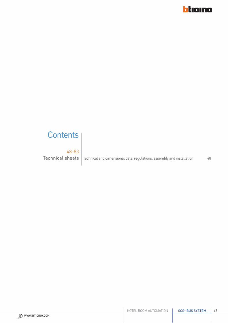
The power supply must be used to supply power to the MY HOME and Lighting Management systems. On the output, the unit supplies a 27 Vdc continuous low voltage, with a maximum current of 600 mA. It is protected by an integrated fuse (not replaceable) against short circuit and overload. It’s a double insulation safety device in accordance with CEI EN60065, and can therefore be used in conjunction with a SELV source in accordance with paragraph 11.1.2.5 of CEI 64-8-4. The power supply unit is fitted inside a 2 DIN rail module enclosure, and its installation must be in accordance with the regulations of the country of use.In general, the following requirements must be met:- The power supply must always be installed in appropriate enclosures.- The device must be kept away from water drips and sprays.- Care must be taken not to obstruct the air vents.- A two-pole circuit breaker must be installed, with contact separation of at least 3 mm
located nearby the power supply. The circuit breaker is used to disconnect the power supply from the mains, and to protect it.
The device must NOT be configured.
Description
BUS SCScompact power supply
EN
Legend
1. Clamps (PRI) for connection to the power supply voltage
2. LED: – green (power supply ON) – red (output current overload)3. Clamps (SCS) for the connection of the BUS/SCS
PRI (AC power supply input)Rated voltage: 220 – 240 VRated current: 175 – 185 mAWorking voltage range: 187 – 265 VWorking frequency range: 47 – 63 HzInput power at full load: 21.5 W maxDissipated power: 5.3 W maxPerformance at full load: 80% typ.Power in stand by: < 1 WOperating temperature: (+5) – (+40) °CIntegrated fuse (PRI side): F1 T2A 250V (CANNOT BE REPLACED)
SCSRated voltage: 27 V +/- 100 mVRated current: 0 – 0.6 ARated power: 16.2 W
Technical data
2 DIN modukes
Dimensional data

49WWW.BTICINO.COM
SCS- BUS SYSTEMHOTEL ROOM AUTOMATION
E46ADCN
01/07/2013MM00273-b-
BUS SCSpower supply
EN
Description
The power supply must be used to supply power to the MY HOME and Lighting Management systems. On the output, the unit supplies a 27 Vdc continuous low voltage, with a maximum current of 1 A. It is electronically protected (without fuses) against short circuit and overload. It’s a double insulation safety device in accordance with CEI EN60065, and can therefore be used in conjunction with a SELV source in accordance with paragraph 11.1.2.5 of CEI 64-8-4.The power supply unit is fitted inside a 8 DIN rail module enclosure, and its installation must be in accordance with the regulations of the country of use.
In general, the following requirements must be met:- The power supply must always be installed in appropriate enclosures.- The device must be kept away from water drips and sprays.- Care must be taken not to obstruct the air vents.- A two-pole circuit breaker must be installed, with contact separation of at least 3 mm
located nearby the power supply. The circuit breaker is used to disconnect the power supply from the mains, and to protect it.
Legend
1. Clamps (1-2) with 27 Vdc output voltage2. Clamps (BUS) for the connection of the BUS/SCS3. Clamps for connection to the power supply voltage
Technical data
Power supply voltage: 230 Vac ± 10% @ 50/60 HzInput MAX power consumption: 300 mAOutput voltage: 27 VdcMaximum power delivered: 1.2 AMaximum power consumption: 11 WReference standards: EN60065Protection index: IP30Operating temperature: 5 – 40 °C
Dimensional data
Size: 8 DIN modules
2
230 ±10% V 50-60Hz
I =300 mAMAX
13
TECHNICAL SHEETS
50
PR I
1 - 2
346020PRI: 220 - 240V~
175-165mA 50/60Hz
1-2: 27Vdc 600mA
1
3
2
346020
20/09/2013BT00659-b-EN
Additional power supply 230 V
Description
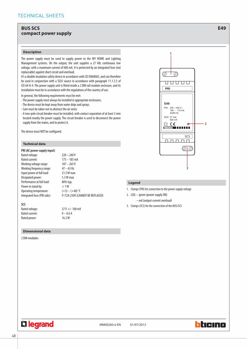
2 DIN module devices which allows to:- locally supply the single video door entry handsets and entrance panels.- supply some accessories of the Communication and MY HOME catalogues (ex: Web server, A/V server, scenario programmers, 2 WIRE/IP interface, switch 10/100, ADSL modem router, Hub-TV and SCS modulator).It is a double insulation safety device in accordance with CEI.The power supply is enclosed by a 2 DIN module plastic rail enclosure, and its installation must be in accordance with the regulations of the country of use.The device must not be configured.
Standards, Certifications, Marks
Standards: CEI EN60065
Technical data
PRI (AC power supply input)Rated voltage: 220 – 240 VacRated current: 180 – 190 mAWorking voltage range: 187 – 265 VWorking frequency range: 47 – 63 HzInput power at full load: 20 W maxDissipated power: 3.8 W (max.)Performance at full load: 80% typ.Power in stand by: < 1 WOperating temperature: 5 – 40 °CIntegrated fuse (PRI side): F1 T2A 250V (CANNOT BE REPLACED)
1 - 2 (DC output):Rated voltage: 27 V +/- 100 mVRated current: 0 – 0.6 ARated power: 16.2 W
Dimensional data
2 DIN modules
Legend
1 - 230 Vac input connection clamps2 - Operating status notification LEDs: (GREEN ON) – normal operation of the power supply (RED ON) – output current overload3 - Output 1 – 2 connection clamps
Assembly, Installation
Comply with the following installation requirements:
- The power supply must always be installed in appropriate enclosures- It must be kept away from water drips and sprays.- Do not to obstruct the air vents.- A double-pole thermal magnetic circuit breaker with contact separation of at least 3
mm must be used, positioned near the power supply. The circuit breaker is used to disconnect the power supply from the mains, and to protect it.

51WWW.BTICINO.COM
SCS- BUS SYSTEMHOTEL ROOM AUTOMATION
H4649 LN4649
1
2
3
5
4
6
0 675 65 5 727 355 722 35
02/10/2013MM00496-b-
BUS-SCS key card switches
EN
Legend
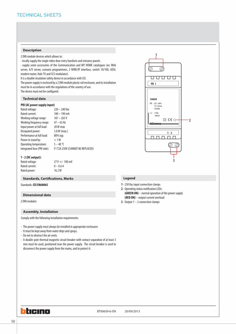
1. Programming key: Learn IN 2. Programming key: Learn OUT3. LED4. Key card detection microswitch5. Configurator socket6. SCS BUS connector
Front view
Rear view
Hotel room power supply key card switch. Thanks to the LED backlit slot, the device can be found in the dark. An automatic switch off delay can also be set. It can be used with key cards with sizes between 45 mm and 54 mm (ISO).The device can be configured in two different ways:- Physical configuration, by inserting the configurators in the appropriate housings.- Configuration using the MyHOME_Suite software, which can be downloaded from
the website www.homesystems-legrandgroup.com; this last type of configuration has the advantage of offering many more options when compared with the physical.configuration.
Description
Size: 2 flush mounted modules
Power supply from SCS BUS: 18-27 VdcMax. absorption: 6 mA Stand-by absorption: 5 mA Operating temperature: (-10) – (+45) °C
Technical data
Dimensional data
EN 60669-2-1EN 50491-5-1EN 50428
Standards, Certifications, Marks

TECHNICAL SHEETS
52
02/10/2013MM00496-b-
H4649 LN4649
0 675 65 5 727 355 722 35
1
2
4
3
EN
BUS-SCS key card switches
2 3 4 5 61
DC - In
MH201
MH201
Two modes:- CENTRALIZED (to be used with MH201), to recall scenarios managed by the scenario
programmer. When the key card is inserted and removed, the device forwards a signal to the scenario programmer, which depending on the scenarios set will activate the corresponding functions programmed.
A = 1-9 (CEN command address)PL = 1-9 (CEN command address)M1 = CENDEL1 = no configuratorM2 = no configuratorDEL2 = no configuratorNote: the insertion of the key card corresponds to “Pushbutton 1” of the control, while the removal of the key card corresponds to “Pushbutton 2” of the control - SCENARIO, where by inserting the key card a group of actuators is enabled, and an
entrance scenario is activated (through the scenario module), and by removing the key card an exit scenario is activated (through the scenario module), thanks to which all the group actuators will switch off and then disable after a set time delay.
A = 1-9 (as scenario module)PL = 1-9 (as scenario module)M1 = 1-8 (activation of the corresponding scenario: see table B)DEL1 = 0 - 9 (switching on time delay at the insertion of the key card: see table A)M2 = no configuratorDEL2 = 0 - 9 (switching off time delay after the removal of the key card: see table A)
SCENARIO mode programming:This operation is performed to create a link between the key card switch and the scenario module. The procedure is as follows:1) Power the key card switch. Check that the scenario module is in programming
mode, with the green LED on;2) Press and hold down programming key 1 (Learn IN) or 2 (Learn OUT) until the LED
starts flashing (approximately 3 seconds); 3) Create the scenario using the system controls and actuators;4) Once the scenario has been saved, briefly press programming key 1 (Learn IN) or 2
(Learn 2) to exit the programming status;5) The scenario module will also have to exit programming status (see the scenario
module technical information).Cancelling the programming in SCENARIO mode:1) Power the key card switch. Check that the scenario module is in programming
mode, with the green LED on:2) Press and hold down programming key 1 (Learn IN) or 2 (Learn 2) for 8 seconds.
after 3 seconds the LED will turn on, after a further 5 seconds it will turn off again;3) Release the key;4) The LED flashing, followed by the LED switching off, indicates that the programming
has been cancelled;5) The scenario module will also have to exit programming status (see the scenario
module technical information).
Note: Sce 1 = scenario activated on insertion Sce 2 = scenario activated on removal Gr = group of actuators
Physical configuration
SCENARIO mode programming
Table AConfigurator value Time
0 01 1 min2 2 min3 3 min4 4 min5 5 min6 10 min7 15 min8 15 sec9 30 sec
Table BConfigurator value Scenario - Group
1 Scenario-group (Sce1=1, Sce2=9, Gr=1)2 Scenario-group (Sce1=2, Sce2=10, Gr=2)3 Scenario-group (Sce1=3, Sce2=11, Gr=3)4 Scenario-group (Sce1=4, Sce2=12, Gr=4)5 Scenario-group (Sce1=5, Sce2=13, Gr=5)6 Scenario-group (Sce1=6, Sce2=14, Gr=6)7 Scenario-group (Sce1=7, Sce2=15, Gr=7)8 Scenario-group (Sce1=8, Sce2=16, Gr=8)
1. Programming key: Learn IN 2. Programming key: Learn OUT3. LED4. Key card detection microswitch
This is performed using the appropriate MyHOME_Suite application. This mode has the advantage of offering many more options when compared with the physical configuration. The software configuration requires Ethernet connection between the system and the PC, through the IP MH201 scenario module.
Configuration using the MyHOME_Suite software
Ethernet connection to the system
HUB Switch
BUS-SCS
PC for configuration
Ethernet network
Ethernet network

53WWW.BTICINO.COM
SCS- BUS SYSTEMHOTEL ROOM AUTOMATION
02/10/2013MM00496-b-
H4649 LN4649
0 675 65 5 727 355 722 35
EN
BUS-SCS key card switches
Wiring diagrams
Principle and configuration diagram for a hotel room
23
45
61
DC
- In
PRI
SCS
E49
PRI:
220 –
240 V
~
185 –
175
mA
50
/60 H
zSC
S: 2
7 Vdc
60
0 mA
MH2
01
MODE
+ – FAN
DND
MUR
R1=
2R2
=7
M=
2L
=0
A=
1PL
=1
T=
2
R1=
2R2
=7
M=
–
A=
9PL
=8
M=
CEN
LED=
–
A=
9PL
=9
M1=
CEN
DEL1
=–
M2=
–DE
L2=
–
ZA=
2ZB
=7
N=
1LO
AD=
–
ZA=
2ZB
=7
TYPE
=1
HEAT
=7
COOL
=CE
NPU
MP=
–IN
=3
MH20
1
E49
3513
230 V
50
Hz
L N
H465
0 LN
4650
0 675
90
230 V
acH4
649
LN46
49
0 675
655 7
27 35
5 722
35
H465
3LN
4653
0 675
93
H465
2 LN
4652
0 675
92
F430
R8
L N
H469
1LN
4691
0 674
59
BC
D
E
A
F
LL1
To ot
her
room
servic
es
HUB S
witch
Othe
r roo
ms
PC fo
r room
man
agem
ent
WIN
DOW
OP
EN
ON ECO
Ethe
rnet
netw
ork
Ethe
rnet
netw
ork
WIN
DOW
CL
OSED
Bell
12 Va
c/dc –
230 V
acma
x 1A
Trans
forme
r
Protec
tion
line
NC co
ntac
t
Magn
etMa
gnet
Cont
act
Cont
act
To th
e fan
-coil
or tem
perat
ure
cont
rol sy
stem
BUS S
CS To ot
her
devic
es
ATh
e gen
eral sw
itch G
S (TM
+EL)
must
be se
lected
based
on th
e abs
orptio
n of
the s
ervice
s insta
lled.
BTh
e TM
switc
h mus
t be s
electe
d bas
ed
on th
e pow
er su
pply
used
.
C
DTh
e TM
switc
h mus
t be s
electe
d bas
ed
on th
e loa
ds co
nnec
ted.
ETh
e actu
ator t
o be u
sed de
pend
s on
the t
ype o
f air c
ondit
ioning
syste
m ins
talled
.
FIf t
he cu
rrent
supp
lied b
y the
E49
is not
suffic
ient t
o pow
er th
e SCS
sys
tem, it
is po
ssible
to us
e the
E4
6ADC
N pow
er su
pply.
ITEM
DESC
RIPTIO
NE4
9Po
wer s
upply
LN46
50Ou
tside
the d
oor in
dicato
rLN
4649
Key c
ard sw
itch
LN46
53DN
D and
MUR
cont
rols
LN46
528 k
ey sc
enar
io co
ntrol
LN46
91Th
ermos
tat w
ith di
splay
MH20
1IP
scena
rio m
odule
F430
R8Air
cond
itionin
g actu
ator
Gene
ral no
te: th
e dev
ices li
sted i
n the
lege
nd ar
e for
the L
iving
Light
serie
s.
CORR
IDOR
RECE
PTIO
N
ROOM
N L V1 V2 V3 Heati
ng
Cooli
ng
TM3
TM1
TM2
GS
(TM+E
L)
TECHNICAL SHEETS
54
H4648 LN4648
1
2
3
4
5
0 675 66 5 727 365 722 36
03/10/2013MM00771-a-
BUS SCS RFID key card switches
EN
Legend
1. Programming key: Learn IN 2. Programming key: Learn OUT3. LED4. Configurator socket5. SCS BUS connector
Front view
Rear view
RFID key card switch for the connection of the power supply to the hotel room (13.56 MHz frequency key card detection). Thanks to the LED backlit slot, the device can be found in the dark. An automatic switch off delay can also be set. It can be used with key cards with sizes between 45 mm and 54 mm (ISO).The device can be configured in two different ways:- Physical configuration, by inserting the configurators in the appropriate housings.- Configuration using the MyHOME_Suite software, which can be downloaded from
the website www.homesystems-legrandgroup.com; this last type of configuration has the advantage of offering many more options when compared with the physical configuration.
Description
Power supply from SCS BUS: 18-27 VdcMax. absorption: 6 mA Stand-by absorption: 5 mA Operating temperature: 5 – 40 °CRFID key card frequency: 13.56 MHz
Technical data
Dimensional data
EN 60669-2-1EN 50491-5-1EN 50428
Standards, Certifications, Marks
Size: 2 flush mounted modules

55WWW.BTICINO.COM
SCS- BUS SYSTEMHOTEL ROOM AUTOMATION
03/10/2013MM00771-a-
H4648 LN4648
0 675 66 5 727 365 722 36
1
2
3
EN
BUS SCS RFID key card switches
2 3 4 5 61
DC - In
MH201
MH201
Two modes:- CENTRALIZED, to recall scenarios managed by the scenario programmer. When
the key card is inserted and removed, the device forwards a signal to the scenario programmer, which depending on the scenarios set will activate the corresponding functions programmed.
A = 1-9 (CEN command address)PL = 1-9 (CEN command address)M1 = CENDEL1 = no configuratorM2 = no configuratorDEL2 = no configuratorNote: the insertion of the key card corresponds to “Pushbutton 1” of the control, while the removal of the key card corresponds to “Pushbutton 2” of the control - SCENARIO, where by inserting the key card a group of actuators is enabled, and an
entrance scenario is activated (through the scenario module), and by removing the key card an exit scenario is activated (through the scenario module), thanks to which all the group actuators will switch off and then disable after a set time delay.
A = 1-9 (as scenario module)PL = 1-9 (as scenario module)M1 = 1-8 (activation of the corresponding scenario: see table B)DEL1 = 0 - 9 (switching on time delay at the insertion of the key card: see table A)M2 = no configuratorDEL2 = 0 - 9 (switching off time delay after the removal of the key card: see table A)
SCENARIO mode programmingThis operation is performed to create a link between the key card switch and the scenario module. The procedure is as follows:1) Power the key card switch. Check that the scenario module is in programming
mode, with the green LED on;2) Press and hold down programming key 1 (Learn IN) or 2 (Learn OUT) until the LED
starts flashing (approximately 3 seconds); 3) Create the scenario using the system controls and actuators;4) Once the scenario has been saved, briefly press programming key 1 (Learn IN) or 2
(Learn 2) to exit the programming status;5) The scenario module will also have to exit programming status (see the scenario
module technical information).Cancelling the programming in SCENARIO mode:1) Power the key card switch. Check that the scenario module is in programming
mode, with the green LED on:2) Press and hold down programming key 1 (Learn IN) or 2 (Learn 2) for 8 seconds.
after 3 seconds the LED will turn on, after a further 5 seconds it will turn off again;3) Release the key;4) The LED flashing, followed by the LED switching off, indicates that the programming
has been cancelled;5) The scenario module will also have to exit programming status (see the scenario
module technical information).
Note: Sce 1 = scenario activated on insertion Sce 2 = scenario activated on removal Gr = group of actuators
Physical configuration
SCENARIO mode programming
Table AConfigurator value Time
0 01 1 min2 2 min3 3 min4 4 min5 5 min6 10 min7 15 min8 15 sec9 30 sec
Table BConfigurator value Scenario - Group
1 Scenario-group (Sce1=1, Sce2=9, Gr=1)2 Scenario-group (Sce1=2, Sce2=10, Gr=2)3 Scenario-group (Sce1=3, Sce2=11, Gr=3)4 Scenario-group (Sce1=4, Sce2=12, Gr=4)5 Scenario-group (Sce1=5, Sce2=13, Gr=5)6 Scenario-group (Sce1=6, Sce2=14, Gr=6)7 Scenario-group (Sce1=7, Sce2=15, Gr=7)8 Scenario-group (Sce1=8, Sce2=16, Gr=8)
1. Programming key: Learn IN 2. Programming key: Learn OUT3. LED
Ethernet connection to the system
HUB Switch
BUS-SCS
PC for configuration
Ethernet network
Ethernet network
This is performed using the appropriate MyHOME_Suite application. This mode has the advantage of offering many more options when compared with the physical configuration. The software configuration requires Ethernet connection between the system and the PC, through the IP MH201 scenario module.
Configuration using the MyHOME_Suite software

TECHNICAL SHEETS
56
03/10/2013MM00771-a-
H4648 LN4648
0 675 66 5 727 365 722 36
EN
BUS SCS RFID key card switches
Wiring diagrams
Principle and configuration diagram for a hotel room
23
45
61
DC
- In
PRI
SCS
E49
PRI:
220 –
240 V
~
185 –
175
mA
50
/60 H
zSC
S: 2
7 Vdc
60
0 mA
MH2
01
MODE
+ – FAN
DND
MUR
R1=
2R2
=7
M=
2L
=0
A=
1PL
=1
T=
2A
=1
PL=
1M
=PU
L
R1=
2R2
=7
M=
–
A=
9PL
=8
M=
CEN
LED=
–
A=
9PL
=9
M1=
CEN
DEL1
=–
M2=
–DE
L2=
–
ZA=
2ZB
=7
N=
1LO
AD=
–
ZA=
2ZB
=7
TYPE
=1
HEAT
=7
COOL
=CE
NPU
MP=
–IN
=3
MH20
1
E49
230 V
50
Hz
L N
H465
1LN
4651
0 675
91
3482
100 6
75 89
F411
/1N
230 V
acH4
648
LN46
480 6
75 66
5 727
365 7
22 36
F430
R8
L N
BC
D
E
A
F
LL1
H469
1LN
4691
0 674
59
H465
3LN
4653
0 675
93
H465
2 LN
4652
0 675
92
3513
To ot
her
room
servic
es
HUB S
witch
Othe
r roo
ms
PC fo
r room
man
agem
ent
To th
e fan
-coil
or tem
perat
ure
cont
rol sy
stem
WIN
DOW
OP
EN
ON ECO
BUS S
CS To ot
her
devic
es
Ethern
et ne
twork
Ethern
et ne
twork
ATh
e gen
eral sw
itch G
S (TM
+EL)
must
be se
lected
based
on th
e abs
orptio
n of
the s
ervice
s insta
lled.
BTh
e TM
switc
h mus
t be s
electe
d bas
ed
on th
e pow
er su
pply
used
.
C
DTh
e TM
switc
h mus
t be s
electe
d bas
ed
on th
e loa
ds co
nnec
ted.
ETh
e actu
ator t
o be u
sed de
pend
s on
the t
ype o
f air c
ondit
ioning
syste
m ins
talled
.
FIf t
he cu
rrent
supp
lied b
y the
E49
is not
suffic
ient t
o pow
er th
e SCS
sys
tem, it
is po
ssible
to us
e the
E4
6ADC
N pow
er su
pply.
ITEM
DESC
RIPTIO
NE4
9Po
wer s
upply
LN46
51Ke
y card
read
er ou
tside
the d
oor a
nd
indica
tors
3482
10Ke
y card
LN46
48Ke
y card
switc
hLN
4653
DND a
nd M
UR co
ntrol
sLN
4652
8 key
scen
ario
cont
rolLN
4691
Therm
ostat
with
disp
layMH
201
IP sce
nario
mod
uleF4
30R8
Air co
nditio
ning a
ctuat
orF4
11/1
NDI
N mod
ule 1
relay
actu
ator
Gene
ral no
te: th
e dev
ices li
sted i
n the
lege
nd ar
e for
the L
iving
Light
serie
s.
CORR
IDOR
RECE
PTIO
N
ROOM
WIN
DOW
CL
OSED
Room
door
electr
ic loc
k
2 sec.
Bell
12 Va
c/dc –
230 V
acma
x 1A
Trans
forme
rTra
nsfor
mer
Protec
tion
line
NC co
ntac
t
Magn
etMa
gnet
Cont
act
Cont
act
N L V1 V2 V3 Heati
ng
Cooli
ng
TM3
TM1
TM2
GS (T
M+EL
)

57WWW.BTICINO.COM
SCS- BUS SYSTEMHOTEL ROOM AUTOMATION
H4653LN4653
02/10/2013MM00775-a-
2
3
1
4
0 675 93DND and MUR flush mounted controlBUS-SCS
EN
Legend
1. LED adjustment/disable pushbutton2. LED:
AXOLUTE/ARTEOR/CÉLIANE: BLUE: message not active PURPLE: message activeLIVINGLIGHT: GREEN: message not active ORANGE: message active
3. Clamps for connection to the SCS BUS 4. Configurator socket
Front view
Flush mounted control for installation inside the room, for the activation of the “Do Not Disturb” or “Make Up Room” notifications on the indicator outside the door.The device can be configured in two different ways:- Physical configuration, by inserting the configurators in the appropriate housings.- Configuration using the MyHOME_Suite software, which can be downloaded from
the website www.homesystems-legrandgroup.com; this last type of configuration has the advantage of offering many more options when compared with the physical.configuration.
Description
Power supply from SCS BUS: 18 – 27 VdcAbsorption: max. 7.5 mAOperating temperature: 5 – 40 °C
Technical data
Size: 2 flush mounted modules
Dimensional data
Rear view
EN 60669-2-1EN 50090-2-2EN 50090-2-3EN 50428
Standards, Certifications, Marks

TECHNICAL SHEETS
58
02/10/2013MM00775-a-
H4653LN4653
0 675 93
100%
0%
30%
60%
DND and MUR flush mounted controlBUS-SCS
EN
DEFAULT
PUSH t > 2 s
2 3 4 5 61
DC - In
MH201
MH201
R1
R2
M
M = 0 DND and MUR active - 2 x 1 module key covers MURDND
M = 1 DND control only - 1 double key cover DND
Physical configuration
R1, R2 = Room address (R1 identifies the tenths; R2 identifies the units)
LED brightness adjustment
This is performed using the appropriate MyHOME_Suite application. This mode has the advantage of offering many more options when compared with the physical configuration. The software configuration requires Ethernet connection between the system and the PC, through the IP MH201 scenario module.
Configuration using the MyHOME_Suite software
Ethernet connection to the system
HUB Switch
BUS-SCS
PC for configuration
Ethernet network
Ethernet network

59WWW.BTICINO.COM
SCS- BUS SYSTEMHOTEL ROOM AUTOMATION
02/10/2013MM00775-a-
H4653LN4653
0 675 93DND and MUR flush mounted controlBUS-SCS
EN
Wiring diagrams
Principle and configuration diagram for a hotel room
23
45
61
DC
- In
PRI
SCS
E49
PRI:
220 –
240 V
~
185 –
175
mA
50
/60 H
zSC
S: 2
7 Vdc
60
0 mA
MH2
01
MODE
+ – FAN
DND
MUR
R1=
2R2
=7
M=
2L
=0
A=
1PL
=1
T=
2A
=1
PL=
1M
=PU
L
R1=
2R2
=7
M=
–
A=
9PL
=8
M=
CEN
LED=
–
A=
9PL
=9
M1=
CEN
DEL1
=–
M2=
–DE
L2=
–
ZA=
2ZB
=7
N=
1LO
AD=
–
ZA=
2ZB
=7
TYPE
=1
HEAT
=7
COOL
=CE
NPU
MP=
–IN
=3
MH20
1
E49
230 V
50
Hz
L N
H465
1LN
4651
0 675
91
3482
100 6
75 89
F411
/1N
230 V
acH4
648
LN46
480 6
75 66
5 727
365 7
22 36
F430
R8
L N
BC
D
E
A
F
LL1
H469
1LN
4691
0 674
59
H465
3LN
4653
0 675
93
H465
2 LN
4652
0 675
92
3513
N L V1 V2 V3
To ot
her
room
servic
es
HUB S
witch
Othe
r roo
ms
PC fo
r room
man
agem
ent
To th
e fan
-coil
or tem
perat
ure
cont
rol sy
stem
WIN
DOW
OP
EN
ON ECO
BUS S
CS To ot
her
devic
es
Ethern
etne
twork
Ethe
rnet
netw
ork
ATh
e gen
eral sw
itch G
S (TM
+EL)
must
be se
lected
based
on th
e abs
orptio
n of
the s
ervice
s insta
lled.
BTh
e TM
switc
h mus
t be s
electe
d bas
ed
on th
e pow
er su
pply
used
.
C
DTh
e TM
switc
h mus
t be s
electe
d bas
ed
on th
e loa
ds co
nnec
ted.
ETh
e actu
ator t
o be u
sed de
pend
s on
the t
ype o
f air c
ondit
ioning
syste
m ins
talled
.
FIf t
he cu
rrent
supp
lied b
y the
E49
is not
suffic
ient t
o pow
er th
e SCS
sys
tem, it
is po
ssible
to us
e the
E4
6ADC
N pow
er su
pply.
ITEM
DESC
RIPTIO
NE4
9Po
wer s
upply
LN46
51Ke
y card
read
er ou
tside
the d
oor a
nd
indica
tors
3482
10Ke
y card
LN46
48Ke
y card
switc
hLN
4653
DND a
nd M
UR co
ntrol
sLN
4652
8 key
scen
ario
cont
rolLN
4691
Therm
ostat
with
disp
layMH
201
IP sce
nario
mod
uleF4
30R8
Air co
nditio
ning a
ctuat
orF4
11/1
NDI
N mod
ule 1
relay
actu
ator
Gene
ral no
te: th
e dev
ices li
sted i
n the
lege
nd ar
e for
the L
iving
Light
serie
s.
WIN
DOW
CL
OSED
Room
door
ele
ctric l
ock
2 sec.
Bell
12 Va
c/dc –
230 V
acma
x 1A
Trans
forme
rTra
nsfor
mer
Protec
tion
line
NC co
ntac
t
Magn
etMa
gnet
Cont
act
Cont
act
CORR
IDOR
RECE
PTIO
N
ROOM
Heati
ngCo
oling
TM3
TM1
TM2
GS
(TM+E
L)

TECHNICAL SHEETS
60
H4650LN4650
1 2
02/10/2013MM00774-a-
34
5
6
7
0 675 90 Outside the door indicator BUS-SCS
EN
Legend
1. DND indicator (red LED on = DO NOT DISTURB)2. MUR indicator (green LED on = MAKE UP ROOM)3. Call pushbutton4. Customisable and backlit area (white LED on)5. Configurator socket6. Clamps for connection to the SCS BUS7. NO contact for the activation of the bell. The contact is controlled by the front
pushbutton
Front view
Rear view
Outside the door indicator with “Do Not Disturb” or “Make Up Room” notifications; it also has a call bell pushbutton. If the DND function is active, the call pushbutton is disabled.The white backlight switch on function can be configured for operating in different modes. See the physical configuration section “L configurator”.The device can be configured in two different ways:- Physical configuration, by inserting the configurators in the appropriate housings.- Configuration using the MyHOME_Suite software, which can be downloaded from
the website www.homesystems-legrandgroup.com; this last type of configuration has the advantage of offering many more options when compared with the physical configuration.
Description
Power supply from SCS BUS: 18 – 27 VdcStand-by absorption: 10 mA 20 mA maxRelay contact (activated by the front pushbutton): 12 Vac/dc – 230 Vac 1A maxOperating temperature: 5 – 40 °C
Technical data
Size: 2 flush mounted modules
Dimensional data
Standards, Certifications, Marks
EN 60669-2-1EN 50491-5-1EN 50428

61WWW.BTICINO.COM
SCS- BUS SYSTEMHOTEL ROOM AUTOMATION
02/10/2013MM00774-a-
H4650LN4650
0 675 90
EN
Outside the door indicator BUS-SCS
R1
R2
M
L
2 3 4 5 61
DC - In
MH201
MH201
R1 = 2R2 = 7M = 2L = 0
Wiring diagrams
Room 127 bell control diagramThe bell is active while the relevant key on the device is pressed.
M = 0 for use together with F420M = 1 for use together with MH200NM = 2 for use together with MH201
L = LED functions
Physical configuration
R1, R2 = Room address (R1 identifies the tenths; R2 identifies the units)
L CONFIGURATOR WHITE BACKLIGHTING LED
RED DND LED
GREEN MUR LED
0 ON: occupied OFF: free Enabled Enabled1 ON: occupied OFF: free Enabled Disabled2 ON: free OFF: occupied Enabled Enabled3 ON: free OFF: occupied Enabled Disabled4 Always ON Enabled Enabled5 Always ON Enabled Disabled6 Always OFF Enabled Enabled 7 Always OFF Enabled Disabled
H4650LN46500 675 90
230 Vac
BUS-SCS
L2L1
Room bell 12 Vac/dc – 230 Vac
1A max
Transformer
This is performed using the appropriate MyHOME_Suite application. This mode has the advantage of offering many more options when compared with the physical configuration. The software configuration requires Ethernet connection between the system and the PC, through the IP MH201 scenario module.
Configuration using the MyHOME_Suite software
Ethernet connection to the system
HUB Switch
BUS-SCS
PC for configuration
Ethernet network
Ethernet network

TECHNICAL SHEETS
62
02/10/2013MM00774-a-
H4650LN4650
0 675 90
EN
Outside the door indicator BUS-SCS
HUB S
witch
Altre
came
re
Principle and configuration diagram for a hotel room
23
45
61
DC
- In
PRI
SCS
E49
PRI:
220 –
240 V
~
185 –
175
mA
50
/60 H
zSC
S: 2
7 Vdc
60
0 mA
MH2
01
MODE
+ – FAN
DND
MUR
R1=
2R2
=7
M=
2L
=0
A=
1PL
=1
T=
2
R1=
2R2
=7
M=
–
A=
9PL
=8
M=
CEN
LED=
–
A=
9PL
=9
M1=
CEN
DEL1
=–
M2=
–DE
L2=
–
ZA=
2ZB
=7
N=
1LO
AD=
–
ZA=
2ZB
=7
TYPE
=1
HEAT
=7
COOL
=CE
NPU
MP=
–IN
=3
MH20
1
E49
3513
230 V
50
Hz
L N
H465
0 LN
4650
0 675
90
230 V
acH4
649
LN46
49
0 675
655 7
27 35
5 722
35
H465
3LN
4653
0 675
93
H465
2 LN
4652
0 675
92
F430
R8
L N
H469
1LN
4691
0 674
59
BC
D
E
A
F
LL1
To ot
her
room
servic
es
HUB S
witch
Othe
r roo
ms
PC fo
r room
man
agem
ent
To th
e fan
-coil
or tem
perat
ure
cont
rol sy
stem
WIN
DOW
OP
EN
ON ECO
BUS S
CS To ot
her
devic
es
Ethern
etne
twork
Ethern
etne
twork
ATh
e gen
eral sw
itch G
S (TM
+EL)
must
be se
lected
based
on th
e abs
orptio
n of
the s
ervice
s insta
lled.
BTh
e TM
switc
h mus
t be s
electe
d bas
ed
on th
e pow
er su
pply
used
.
C
DTh
e TM
switc
h mus
t be s
electe
d bas
ed
on th
e loa
ds co
nnec
ted.
ETh
e actu
ator t
o be u
sed de
pend
s on
the t
ype o
f air c
ondit
ioning
syste
m ins
talled
.
FIf t
he cu
rrent
supp
lied b
y the
E49
is not
suffic
ient t
o pow
er th
e SCS
sys
tem, it
is po
ssible
to us
e the
E4
6ADC
N pow
er su
pply.
ITEM
DESC
RIPTIO
NE4
9Po
wer s
upply
LN46
50Ou
tside
the d
oor in
dicato
rLN
4649
Key c
ard sw
itch
LN46
53DN
D and
MUR
cont
rols
LN46
528 k
ey sc
enar
io co
ntrol
LN46
91Th
ermos
tat w
ith di
splay
MH20
1IP
scena
rio m
odule
F430
R8Air
cond
itionin
g actu
ator
Gene
ral no
te: th
e dev
ices li
sted i
n the
lege
nd ar
e for
the L
iving
Light
serie
s.
WIN
DOW
CL
OSED
Bell
12 Va
c/dc –
230 V
acma
x 1A
Trans
forme
r
Protec
tion
line
NC co
ntac
t
Magn
etMa
gnet
Cont
act
Cont
act
N L V1 V2 V3 Heati
ng
Cooli
ng
CORR
IDOR
RECE
PTIO
N
ROOM
TM3
TM1
TM2
GS
(TM+E
L)

63WWW.BTICINO.COM
SCS- BUS SYSTEMHOTEL ROOM AUTOMATION
H4651LN4651
02/10/2013MM00776-a-
1 2 3
46
5
7
8
0 675 91
9
RFID reader and outside the door indicatorBUS SCS
EN
Outside the door indicator with “Do Not Disturb” and “Make UP Room” notification, call bell pushbutton, RFID key card reader (13.56 MHz frequency key card detection), and room occupied notification.The white backlight switch on function can be configured for operating in different modes. See the physical configuration section “L configurator”.The device can be configured in two different ways:- Physical configuration, by inserting the configurators in the appropriate housings.- Configuration using the MyHOME_Suite software, which can be downloaded from
the website www.homesystems-legrandgroup.com; this last type of configuration has the advantage of offering many more options when compared with the physical configuration.
Description
Power supply from SCS BUS: 18 – 27 VdcAbsorption: in Stand-by 10 mA with relay active 20 mA max. with RFID 55 mARelay contact (activated by the front pushbutton): 12 Vac/dc – 230 Vac 1A maxOperating temperature: 5 – 40 °C
Technical data
Size: 2 flush mounted modules
Dimensional data
Legend
1. DND indicator (red LED on = DO NOT DISTURB)2. Green LED on = reading OK
Red LED on = reading error LED flashing = stand alone mode key card programming
3. MUR indicator (green LED on = MAKE UP ROOM)4. Call pushbutton (it activates the internal relay)5. RFID key card reader6. Customisable and backlit area (white LED on)7. Configurator socket8. Clamps for connection to the SCS BUS9. NO relay contact; the relay can be used to control:
- bell - electric door lock The relay is activated by the front pushbutton.
Front view
Rear view
EN 60669-2-1EN 50491-5-1EN 50428
Standards, Certifications, Marks
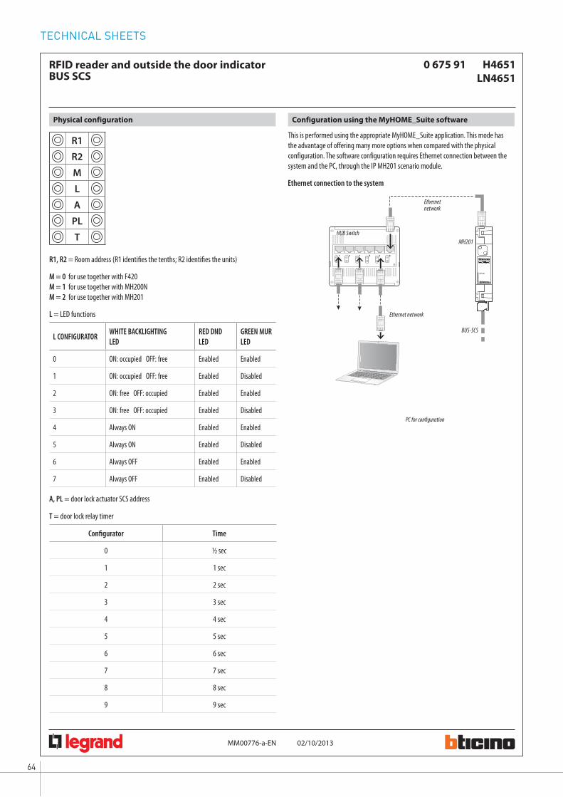
TECHNICAL SHEETS
64
H4651LN4651
02/10/2013MM00776-a-
0 675 91RFID reader and outside the door indicatorBUS SCS
EN
2 3 4 5 61
DC - In
MH201
MH201
This is performed using the appropriate MyHOME_Suite application. This mode has the advantage of offering many more options when compared with the physical configuration. The software configuration requires Ethernet connection between the system and the PC, through the IP MH201 scenario module.
Configuration using the MyHOME_Suite softwarePhysical configuration
R1
R2
M
L
A
PL
T
M = 0 for use together with F420M = 1 for use together with MH200NM = 2 for use together with MH201
L = LED functions
A, PL = door lock actuator SCS address
T = door lock relay timer
R1, R2 = Room address (R1 identifies the tenths; R2 identifies the units)
Configurator Time
0 1⁄2 sec
1 1 sec
2 2 sec
3 3 sec
4 4 sec
5 5 sec
6 6 sec
7 7 sec
8 8 sec
9 9 sec
L CONFIGURATOR WHITE BACKLIGHTING LED
RED DND LED
GREEN MUR LED
0 ON: occupied OFF: free Enabled Enabled
1 ON: occupied OFF: free Enabled Disabled
2 ON: free OFF: occupied Enabled Enabled
3 ON: free OFF: occupied Enabled Disabled
4 Always ON Enabled Enabled
5 Always ON Enabled Disabled
6 Always OFF Enabled Enabled
7 Always OFF Enabled Disabled
Ethernet connection to the system
HUB Switch
BUS-SCS
PC for configuration
Ethernet network
Ethernet network

65WWW.BTICINO.COM
SCS- BUS SYSTEMHOTEL ROOM AUTOMATION
H4651LN4651
02/10/2013MM00776-a-
0 675 91RFID reader and outside the door indicatorBUS SCS
EN
110
H4651LN4651
0 675 91
H4651LN4651
0 675 91
F411/1N
230 Vac
230 Vac
BUS-SCS
BUS-SCS
L
L
L1
L1
R1 = 1R2 = 5M = 2L = –A = –PL = –T = 3
R1 = 1R2 = 0M = 2L = –A = 1PL = 1T = 2
A = 1PL = 1M = PUL
Stand-alone mode key card programming
Programming the key card using the PC and the software
Master key card programmingIf no master key card has been programmed, at the first start up the DND & MUR indicator accepts all the key cards.To start the Master key card programming procedure press the call pushbutton for 10 seconds and then move the key card close to the reader; this key card will be saved as Master.The programming of the Master key card cannot be changed; however the device can be reset as follows:- Disconnect the power supply from the device. - Reconnect the power supply while pressing the call pushbutton for 10 seconds.NOTE: this procedure deletes all the key cards saved by the device.
Customer key card programming- Move the Master key card close to the reader; the green LED starts flashing slowly.- Move the customer key card to save close to the reader, the green LED stays on steady
for two seconds.- Press the call pushbutton to end the operation (the green LED goes off).
Deleting all the saved customer key cards- Move the Master key card close to the reader; the green LED starts flashing slowly.- Move the key card close to the reader again, the green LED starts flashing quickly.- Move the key card close to the reader a third time, the green LED comes on steady for
five seconds before switching off.
Service key card programming- Move the Master key card close to the reader; the green LED starts flashing slowly.- Press the call pushbutton; the LED starts flashing orange.- Move the service key card to save close to the reader, the orange LED stays on steady
for two seconds.- Press the call pushbutton to end the operation (the orange LED goes off).
Deleting all the service key cards- Move the Master key card close to the reader; the green LED starts flashing slowly.- Press the call pushbutton; the LED starts flashing orange.- Move the Master key card close to the reader again, the LED starts flashing quickly.- Move the key card close to the reader a third time, the orange LED comes on steady
for five seconds before switching off.
Programming key cards using the PC and the relevant software provides further functions in addition to the basic ones available in stand-alone mode programming: validity settings, guest information, scheduled accesses...This procedure is only possible using item MH201.
Wiring diagrams
The electric door lock is activated for a period of 3 seconds by the RFID reader following a positive reading of the key card. In this mode the front pushbutton is disabled.
The bell is activated by the front pushbutton of the reader and indicator outside the door.The electric door lock is activated for a period of 2 seconds by the reader and indicator outside the door following a positive reading of the key card.
Room door electric lock 12 Vac/dc – 230 Vac
1A max
Bell
12 Vac/dc – 230 Vac1A max
Transformer
Transformer
Transformer
Room door electric lock
2 sec
Room 110 bell + electric door lock control diagram
Room 115 electric door lock control diagram

TECHNICAL SHEETS
66
H4651LN4651
02/10/2013MM00776-a-
0 675 91RFID reader and outside the door indicatorBUS SCS
EN
Principle and configuration diagram for a hotel room
23
45
61
DC
- In
PRI
SCS
E49
PRI:
220 –
240 V
~
185 –
175
mA
50
/60 H
zSC
S: 2
7 Vdc
60
0 mA
MH2
01
MODE
+ – FAN
DND
MUR
R1=
2R2
=7
M=
2L
=0
A=
1PL
=1
T=
2A
=1
PL=
1M
=PU
L
R1=
2R2
=7
M=
–
A=
9PL
=8
M=
CEN
LED=
–
A=
9PL
=9
M1=
CEN
DEL1
=–
M2=
–DE
L2=
–
ZA=
2ZB
=7
N=
1LO
AD=
–
ZA=
2ZB
=7
TYPE
=1
HEAT
=7
COOL
=CE
NPU
MP=
–IN
=3
MH20
1
E49
230 V
50
Hz
L N
F411
/1N
230 V
acH4
648
LN46
480 6
75 66
5 727
365 7
22 36
F430
R8
L N
BC
D
E
A
F
LL1
H469
1LN
4691
0 674
59
H465
3LN
4653
0 675
93
H465
2 LN
4652
0 675
92
3513
H465
1LN
4651
0 675
91
3482
100 6
75 89
To ot
her
room
servic
es
HUB S
witch
Othe
r roo
ms
PC fo
r room
man
agem
ent
To th
e fan
-coil
or tem
perat
ure
cont
rol sy
stem
WIN
DOW
OP
EN
ON ECO
BUS S
CS To ot
her
devic
es
Ethern
etne
twork
Ethern
etne
twork
ATh
e gen
eral sw
itch G
S (TM
+EL)
must
be se
lected
based
on th
e abs
orptio
n of
the s
ervice
s insta
lled.
BTh
e TM
switc
h mus
t be s
electe
d bas
ed
on th
e pow
er su
pply
used
.
C
DTh
e TM
switc
h mus
t be s
electe
d bas
ed
on th
e loa
ds co
nnec
ted.
ETh
e actu
ator t
o be u
sed de
pend
s on
the t
ype o
f air c
ondit
ioning
syste
m ins
talled
.
FIf t
he cu
rrent
supp
lied b
y the
E49
is not
suffic
ient t
o pow
er th
e SCS
sys
tem, it
is po
ssible
to us
e the
E4
6ADC
N pow
er su
pply.
ITEM
DESC
RIPTIO
NE4
9Po
wer s
upply
LN46
51Ke
y card
read
er ou
tside
the d
oor
and i
ndica
tors
3482
10Ke
y card
LN46
48Ke
y card
switc
hLN
4653
DND a
nd M
UR co
ntrol
sLN
4652
8 key
scen
ario
cont
rolLN
4691
Therm
ostat
with
disp
layMH
201
IP sce
nario
mod
uleF4
30R8
Air co
nditio
ning a
ctuat
orF4
11/1
NDI
N mod
ule 1
relay
actu
ator
Gene
ral no
te: th
e dev
ices li
sted i
n the
lege
nd ar
e for
the L
iving
Light
serie
s.
CORR
IDOR
RECE
PTIO
N
ROOM
WIN
DOW
CL
OSED
Room
door
ele
ctric l
ock
2 sec.
Bell
12 Va
c/dc –
230 V
acma
x 1A
Trans
forme
rTra
nsfor
mer
Protec
tion
line
NC co
ntac
t
Magn
etMa
gnet
Cont
act
Cont
act
N L V1 V2 V3 Heati
ng
Cooli
ng
TM1
TM2
TM3
GS
(TM+E
L)

67WWW.BTICINO.COM
SCS- BUS SYSTEMHOTEL ROOM AUTOMATION
H4652LN4652
16/09/2013MM00778-a-
0 675 928 key multifunction controlBUS SCS
EN
1
2
1
35
4
Flush mounted multifunction control, with 8 backlit keys in the centre section, where the icons indicating the functions allocated to the keys can be found.The device can be configured in two different ways:- Physical configuration, by inserting the configurators in the appropriate housings.- Configuration using the MyHOME_Suite software, which can be downloaded from
the website www.homesystems-legrandgroup.com; this last type of configuration has the advantage of offering many more options when compared with the physical.configuration.
Irrespective of the mode implemented, an A/PL address must always be assigned to the control. In can be programmed in 4 operating modes:- The self-learning mode (cyclical or non cyclical) gives the possibility of associating
to each key the majority of the typical controls of the automation, sound, and video door entry (staircase lights, door lock, call to the floor, door lock and camera cycling) systems, in addition to the auxiliary controls.
- The scenario mode gives the possibility of recalling, programming and deleting 8 scenarios of a scenario module.
- The swivelling mode gives the possibility of driving 4 light points of shutters in succession (room or group).
- CEN mode gives the possibility of using the control together with scenario programmer MH200N or MH201.
Description
Legend
1. Keys2. Customisable labels3. Clamps for connection to the SCS BUS4. Configurator socket5. Programming pushbutton for self-learning and scenario modes
Front view
Rear view
Power supply from SCS BUS: 18 – 27 VdcAbsorption: with LEDs Off: 5 mA with LEDs On at 100%: 20 mAOperating temperature: 0 – 40 °C
Technical data
3541 - 0 675 95 A5 sheets with symbol customisations, BLACK3542 - 0 675 96 A5 sheets with symbol customisations, WHITEFor the customisation of the sheets, it is possible to use the tool found in the MyHOME_Suite configuration software, which can be downloaded from the websi-te www.homesystems-legrandgroup.com.
Related items
Size: 2 flush mounted modules
Dimensional data
EN 60669-2-1EN 50491-5-1EN 50428
Standards, Certifications, Marks
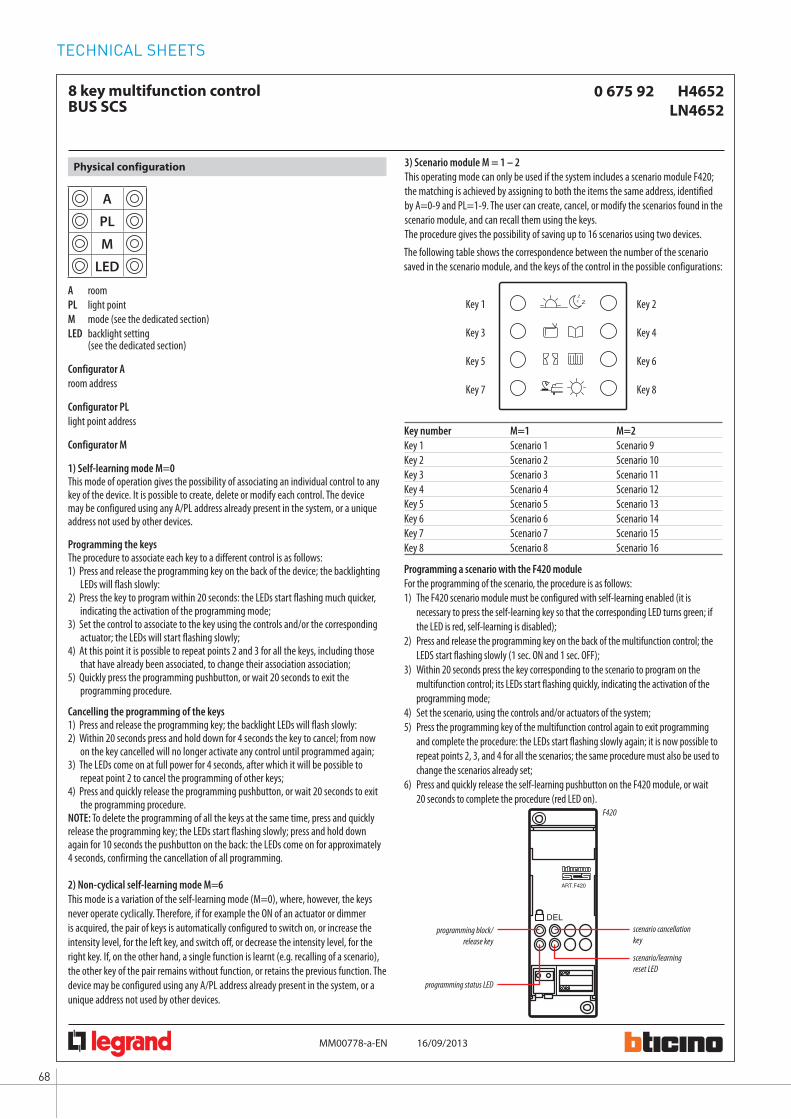
TECHNICAL SHEETS
68
16/09/2013MM00778-a-
H4652LN4652
0 675 928 key multifunction controlBUS SCS
EN
A
PL
M
LED
Physical configuration
Configurator M
Configurator Aroom address
Configurator PLlight point address
1) Self-learning mode M=0This mode of operation gives the possibility of associating an individual control to any key of the device. It is possible to create, delete or modify each control. The device may be configured using any A/PL address already present in the system, or a unique address not used by other devices.
2) Non-cyclical self-learning mode M=6This mode is a variation of the self-learning mode (M=0), where, however, the keys never operate cyclically. Therefore, if for example the ON of an actuator or dimmer is acquired, the pair of keys is automatically configured to switch on, or increase the intensity level, for the left key, and switch off, or decrease the intensity level, for the right key. If, on the other hand, a single function is learnt (e.g. recalling of a scenario), the other key of the pair remains without function, or retains the previous function. The device may be configured using any A/PL address already present in the system, or a unique address not used by other devices.
3) Scenario module M = 1 – 2This operating mode can only be used if the system includes a scenario module F420; the matching is achieved by assigning to both the items the same address, identified by A=0-9 and PL=1-9. The user can create, cancel, or modify the scenarios found in the scenario module, and can recall them using the keys.The procedure gives the possibility of saving up to 16 scenarios using two devices.
Programming the keysThe procedure to associate each key to a different control is as follows:1) Press and release the programming key on the back of the device; the backlighting
LEDs will flash slowly:2) Press the key to program within 20 seconds: the LEDs start flashing much quicker,
indicating the activation of the programming mode;3) Set the control to associate to the key using the controls and/or the corresponding
actuator; the LEDs will start flashing slowly;4) At this point it is possible to repeat points 2 and 3 for all the keys, including those
that have already been associated, to change their association association;5) Quickly press the programming pushbutton, or wait 20 seconds to exit the
programming procedure.
Cancelling the programming of the keys1) Press and release the programming key; the backlight LEDs will flash slowly:2) Within 20 seconds press and hold down for 4 seconds the key to cancel; from now
on the key cancelled will no longer activate any control until programmed again;3) The LEDs come on at full power for 4 seconds, after which it will be possible to
repeat point 2 to cancel the programming of other keys;4) Press and quickly release the programming pushbutton, or wait 20 seconds to exit
the programming procedure.NOTE: To delete the programming of all the keys at the same time, press and quickly release the programming key; the LEDs start flashing slowly; press and hold down again for 10 seconds the pushbutton on the back: the LEDs come on for approximately 4 seconds, confirming the cancellation of all programming.
A room PL light point M mode (see the dedicated section)LED backlight setting (see the dedicated section)
DEL
ART.F420
F420
Programming a scenario with the F420 moduleFor the programming of the scenario, the procedure is as follows:1) The F420 scenario module must be configured with self-learning enabled (it is
necessary to press the self-learning key so that the corresponding LED turns green; if the LED is red, self-learning is disabled);
2) Press and release the programming key on the back of the multifunction control; the LEDS start flashing slowly (1 sec. ON and 1 sec. OFF);
3) Within 20 seconds press the key corresponding to the scenario to program on the multifunction control; its LEDs start flashing quickly, indicating the activation of the programming mode;
4) Set the scenario, using the controls and/or actuators of the system;5) Press the programming key of the multifunction control again to exit programming
and complete the procedure: the LEDs start flashing slowly again; it is now possible to repeat points 2, 3, and 4 for all the scenarios; the same procedure must also be used to change the scenarios already set;
6) Press and quickly release the self-learning pushbutton on the F420 module, or wait 20 seconds to complete the procedure (red LED on).
The following table shows the correspondence between the number of the scenario saved in the scenario module, and the keys of the control in the possible configurations:
Key number M=1 M=2Key 1 Scenario 1 Scenario 9Key 2 Scenario 2 Scenario 10Key 3 Scenario 3 Scenario 11Key 4 Scenario 4 Scenario 12Key 5 Scenario 5 Scenario 13Key 6 Scenario 6 Scenario 14Key 7 Scenario 7 Scenario 15Key 8 Scenario 8 Scenario 16
Key 1 Key 2
Key 5 Key 6
Key 3 Key 4
Key 7 Key 8
scenario cancellation key
scenario/learning reset LED
programming block/release key
programming status LED

69WWW.BTICINO.COM
SCS- BUS SYSTEMHOTEL ROOM AUTOMATION
16/09/2013MM00778-a-
H4652LN4652
0 675 928 key multifunction controlBUS SCS
EN
2 3 4 5 61
DC - In
MH201
MH201
Deleting a scenarioTo delete the scenario, the procedure is as follows:1) The F420 scenario module must be in configuration mode with self-learning enabled;2) Press and release the programming key of the multifunction control; the LEDS start
flashing slowly (1 sec. ON and 1 sec. OFF);3) Within 20 seconds press and hold down for 4 seconds the key of the scenario to be
cancelled on the multifunction control;4) The LEDs flash quickly for 4 seconds, after which it will be possible to repeat point 2 to
delete the other programming.5) Press and quickly release the programming pushbutton on the back of the control, or
wait 20 seconds to exit the deleting procedure.NOTE: to reset the whole memory, it will be necessary to directly act on the scenario module: press “DEL” for ten seconds, after enabling the scenario module for programming.
4) Swivelling modes M=0/I; ↑↓; ↑↓MThese modes ensure quick installation without the need for further learning, or scenario modules, enabling the control of 4 light points or shutters with consecutive addresses. The A PL address is the light point or shutter controlled by the first pair of keys (the keys are paired horizontally), the subsequent pairs controls the subsequent light points or shutters. If the Amb or Gr configurators are connected to A, in the same way, the 4 pairs of keys control consecutive rooms or groups starting from the one indicated by the PL configurator.
5) Scenario programmer mode, M=CENThe matching between a scenario configured in the scenario programmer MH200N or MH201, and the corresponding controls keys of the multifunction control, is completed during the programming of the scenario itself using the dedicated software.Always assign to the control a unique A/PL address on the system (it must not be used by any other device installed on the BUS); the A=0, PL=0 configuration is not acceptable. This operating mode can only be used if the system includes a scenario programmer (MH200 or MH201).
Possible function Value of M configurator
ON/OFF control: On control with the left key, Off control with the right key. For point-to-point controls the key perform the On/Off function with a short pressure andthe adjustment with an extended pressure: for the other controls, only On/Off are performed
0/I
Control (UP/DOWN for shutters): up and down control, until fully open or closed
↑↓
Monostable control (UP/DOWN for shutters): up and down control, for the time the key is pressed
↑↓M
LED configuratorSetting the backlight intensityThe configurator in the LED housing gives the possibility of setting the backlight at the desired level; see table:
LED configurator Brightness level
0 default setting = 30%
1 level 10 %
2 level 15 %
3 level 20 %
4 level 25 %
5 level 30 %
6 level 40 %
7 level 50 %
8 level 60 %
9 level 80 %
OFF level OFF
ON level 100 %
This is performed using the appropriate MyHOME_Suite application. This mode has the advantage of offering many more options when compared with the physical configuration. The software configuration requires Ethernet connection between the system and the PC, through the IP MH201 scenario module.
Configuration using the software in a typical hotel system
Ethernet connection to the system
HUB Switch
BUS-SCS
PC for room management
Ethernet network
Ethernet network
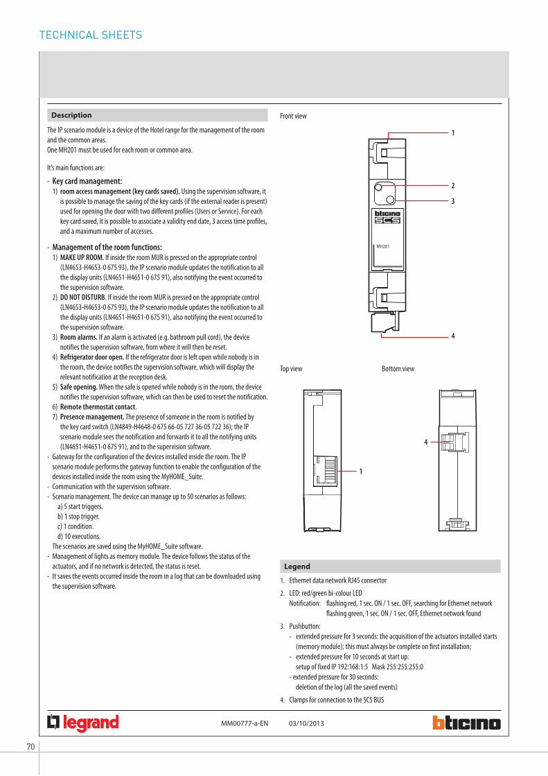
TECHNICAL SHEETS
70
MH201
03/10/2013MM00777-a-
IP scenario moduleBUS-SCS
EN
1
4
MH201
2
3
1
4
The IP scenario module is a device of the Hotel range for the management of the room and the common areas.One MH201 must be used for each room or common area.
It’s main functions are:
- Key card management: 1) room access management (key cards saved). Using the supervision software, it
is possible to manage the saving of the key cards (if the external reader is present) used for opening the door with two different profiles (Users or Service). For each key card saved, it is possible to associate a validity end date, 3 access time profiles, and a maximum number of accesses.
- Management of the room functions: 1) MAKE UP ROOM. If inside the room MUR is pressed on the appropriate control
(LN4653-H4653-0 675 93), the IP scenario module updates the notification to all the display units (LN4651-H4651-0 675 91), also notifying the event occurred to the supervision software.
2) DO NOT DISTURB. If inside the room MUR is pressed on the appropriate control (LN4653-H4653-0 675 93), the IP scenario module updates the notification to all the display units (LN4651-H4651-0 675 91), also notifying the event occurred to the supervision software.
3) Room alarms. If an alarm is activated (e.g. bathroom pull cord), the device notifies the supervision software, from where it will then be reset.
4) Refrigerator door open. If the refrigerator door is left open while nobody is in the room, the device notifies the supervision software, which will display the relevant notification at the reception desk.
5) Safe opening. When the safe is opened while nobody is in the room, the device notifies the supervision software, which can then be used to reset the notification.
6) Remote thermostat contact. 7) Presence management. The presence of someone in the room is notified by
the key card switch (LN4849-H4648-0 675 66-05 727 36-05 722 36); the IP scenario module sees the notification and forwards it to all the notifying units (LN4651-H4651-0 675 91), and to the supervision software.
- Gateway for the configuration of the devices installed inside the room. The IP scenario module performs the gateway function to enable the configuration of the devices installed inside the room using the MyHOME_Suite.
- Communication with the supervision software.- Scenario management. The device can manage up to 50 scenarios as follows:
a) 5 start triggers.b) 1 stop trigger.c) 1 condition.d) 10 executions.
The scenarios are saved using the MyHOME_Suite software.- Management of lights as memory module. The device follows the status of the
actuators, and if no network is detected, the status is reset.- It saves the events occurred inside the room in a log that can be downloaded using
the supervision software.
Description
Legend
1. Ethernet data network RJ45 connector2. LED: red/green bi-colour LED
Notification: flashing red, 1 sec. ON / 1 sec. OFF, searching for Ethernet network flashing green, 1 sec. ON / 1 sec. OFF, Ethernet network found
3. Pushbutton: - extended pressure for 3 seconds: the acquisition of the actuators installed starts (memory module); this must always be complete on first installation; - extended pressure for 10 seconds at start up: setup of fixed IP 192:168:1:5 Mask 255:255:255:0 - extended pressure for 30 seconds: deletion of the log (all the saved events)
4. Clamps for connection to the SCS BUS
Front view
Top view Bottom view

71WWW.BTICINO.COM
SCS- BUS SYSTEMHOTEL ROOM AUTOMATION
MH201
03/10/2013MM00777-a-
IP scenario moduleBUS-SCS
EN
Putting into operation
- The first time it is switched on, press the pushbutton to start the acquisition by the module of the devices installed in the room.
- The extended pressure (over 10 seconds) of the pushbutton is used to configure the fixed IP address: IP 192.168.1.5 Subnet Mask: 255.255.255.0
Power supply: 18 – 27 VdcAbsorption: 30 mAOperating temperature: 5 – 40 °C
Technical data
Size: 1 DIN module
Dimensional data
Configuration
The configuration of the scenarios can be completed using the “MyHOME_Suite” software. It is possible to save up to 50 scenarios.Always using the software, it is possible to change the basic settings of the device:- Name: max. 16 characters- Open Password: default 12345 (max 9 characters)
EN 60669-2-1EN 50491-5-1EN 50428
Standards, Certifications, Marks

TECHNICAL SHEETS
72
MH201
03/10/2013MM00777-a-
IP scenario moduleBUS-SCS
EN
Typical wiring diagram with max 100 rooms or common areas
2 3 4 5 61
DC - In
MH201
MODE
+
–
FAN
DND MUR
2 3 4 5 61
DC - In
MH201
MODE
+
–
FAN
DND MUR
2 3 4 5 61
DC - In
MH201
MODE
+
–
FAN
DND MUR
101
201
301SCS
E49PRI: 220 – 240 V~ 185 – 175 mA 50/60 HzSCS: 27 Vdc 600 mA
SCS
E49PRI: 220 – 240 V~ 185 – 175 mA 50/60 HzSCS: 27 Vdc 600 mA
SCS
E49PRI: 220 – 240 V~ 185 – 175 mA 50/60 HzSCS: 27 Vdc 600 mA
3482100 675 89
348402
MH201
MH201
MH201
BUS SCS
BUS SCS
BUS SCS
H4651LN46510 675 91
H4651LN46510 675 91
H4651LN46510 675 91
H4648 LN46480 675 665 727 365 722 36
H4648 LN46480 675 665 727 365 722 36
H4648 LN46480 675 665 727 365 722 36
H4653LN46530 675 93
H4653LN46530 675 93
H4653LN46530 675 93
H4652 LN46520 675 92
H4652 LN46520 675 92
H4652 LN46520 675 92
H4691LN46910 674 59
H4691LN46910 674 59
H4691LN46910 674 59
E49
E49
E49
RECEPTION
1st FLOOR
2nd FLOOR
3rd FLOOR
TO THE OTHER FLOORS
ROOM 101
ROOM 201
ROOM 301
HUB Switch
HUB Switch
HUB Switch
To the other rooms
To the other rooms
To the other rooms
PC + software for room management
USB cable
Existing hotel Ethernet network

73WWW.BTICINO.COM
SCS- BUS SYSTEMHOTEL ROOM AUTOMATION
MH201
03/10/2013MM00777-a-
IP scenario moduleBUS-SCS
EN
Wiring diagrams
Principle and configuration diagram for a hotel room
23
45
61
DC
- In
PRI
SCS
E49
PRI:
220 –
240 V
~
185 –
175
mA
50
/60 H
zSC
S: 2
7 Vdc
60
0 mA
MH2
01
MODE
+ – FAN
DND
MUR
R1=
2R2
=7
M=
2L
=0
A=
1PL
=1
T=
2
R1=
2R2
=7
M=
–
A=
9PL
=8
M=
CEN
LED=
–
A=
9PL
=9
M1=
CEN
DEL1
=–
M2=
–DE
L2=
–
ZA=
2ZB
=7
N=
1LO
AD=
–
ZA=
2ZB
=7
TYPE
=1
HEAT
=7
COOL
=CE
NPU
MP=
–IN
=3
MH20
1
E49
230 V
50
Hz
L N
F411
/1N
230 V
acH4
648
LN46
480 6
75 66
5 727
365 7
22 36
F430
R8
L N
BC
D
E
A
F
LL1
H469
1LN
4691
0 674
59
H465
3LN
4653
0 675
93
H465
2 LN
4652
0 675
92
3513
H465
1LN
4651
0 675
91
3482
100 6
75 89
N L V1 V2 V3
A=
1PL
=1
M=
PUL
To ot
her
room
servic
es
HUB S
witch
Othe
r roo
ms
PC fo
r room
man
agem
ent
To th
e fan
-coil
or tem
perat
ure
cont
rol sy
stem
WIN
DOW
OP
EN
ON
BUS S
CS To ot
her
devic
es
Ethern
et ne
twork
Ethern
et ne
twork
ATh
e gen
eral sw
itch G
S (TM
+EL)
must
be se
lected
based
on th
e abs
orptio
n of
the s
ervice
s insta
lled.
BTh
e TM
switc
h mus
t be s
electe
d bas
ed
on th
e pow
er su
pply
used
.
C
DTh
e TM
switc
h mus
t be s
electe
d bas
ed
on th
e loa
ds co
nnec
ted.
ETh
e actu
ator t
o be u
sed de
pend
s on
the t
ype o
f air c
ondit
ioning
syste
m ins
talled
.
FIf t
he cu
rrent
supp
lied b
y the
E49
is not
suffic
ient t
o pow
er th
e SCS
sys
tem, it
is po
ssible
to us
e the
E4
6ADC
N pow
er su
pply.
ITEM
DESC
RIPTIO
NE4
9Po
wer s
upply
LN46
51Ke
y card
read
er ou
tside
the d
oor a
nd
indica
tors
3482
10Ke
y card
LN46
48Ke
y card
switc
hLN
4653
DND a
nd M
UR co
ntrol
sLN
4652
8 key
scen
ario
cont
rolLN
4691
Therm
ostat
with
disp
layMH
201
IP sce
nario
mod
uleF4
30R8
Air co
nditio
ning a
ctuat
orF4
11/1
NDI
N mod
ule 1
relay
actu
ator
Gene
ral no
te: th
e dev
ices li
sted i
n the
lege
nd ar
e for
the L
iving
Light
serie
s.
CORR
IDOR
RECE
PTIO
N
ROOM
WIN
DOW
CL
OSED
Room
door
ele
ctric l
ock
2 sec.
Bell
12 Va
c/dc –
230 V
acma
x 1A
Trans
forme
rTra
nsfor
mer
Protec
tion
line
NC co
ntac
t
Magn
etMa
gnet
Cont
act
Cont
act
ECO
Heati
ng
Cooli
ng
GS
(TM+E
L)
TM3
TM1
TM2
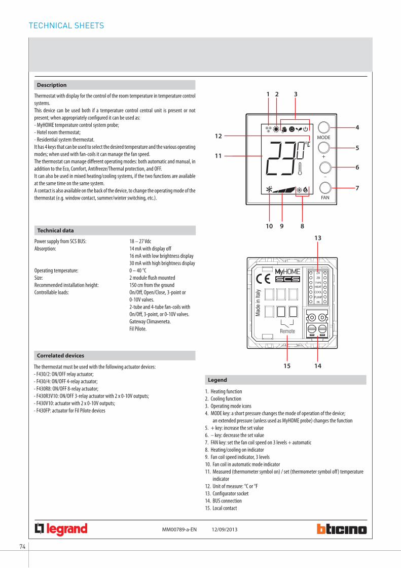
TECHNICAL SHEETS
74
MM00789-a-
H4691 LN4691
06745964170
EN
Thermostat with display
12/09/2013
13
1415
7
4
5
6
3
10
11
12
9
1 2
8
MODE
+
–
FAN
Thermostat with display for the control of the room temperature in temperature control systems.This device can be used both if a temperature control central unit is present or not present; when appropriately configured it can be used as:- MyHOME temperature control system probe;- Hotel room thermostat;- Residential system thermostat.It has 4 keys that can be used to select the desired temperature and the various operating modes; when used with fan-coils it can manage the fan speed.The thermostat can manage different operating modes: both automatic and manual, in addition to the Eco, Comfort, Antifreeze/Thermal protection, and OFF.It can also be used in mixed heating/cooling systems, if the two functions are available at the same time on the same system.A contact is also available on the back of the device, to change the operating mode of the thermostat (e.g. window contact, summer/winter switching, etc.).
Description
Power supply from SCS BUS: 18 – 27 VdcAbsorption: 14 mA with display off 16 mA with low brightness display 30 mA with high brightness displayOperating temperature: 0 – 40 °CSize: 2 module flush mountedRecommended installation height: 150 cm from the groundControllable loads: On/Off, Open/Close, 3-point or
0-10V valves. 2-tube and 4-tube fan-coils with
On/Off, 3-point, or 0-10V valves. Gateway Climaveneta. Fil Pilote.
Technical data
Correlated devices
The thermostat must be used with the following actuator devices:- F430/2: ON/OFF relay actuator;- F430/4: ON/OFF 4-relay actuator;- F430R8: ON/OFF 8-relay actuator;- F430R3V10: ON/OFF 3-relay actuator with 2 x 0-10V outputs;- F430V10: actuator with 2 x 0-10V outputs;- F430FP: actuator for Fil Pilote devices
Legend
1. Heating function 2. Cooling function3. Operating mode icons 4. MODE key: a short pressure changes the mode of operation of the device;
an extended pressure (unless used as MyHOME probe) changes the function5. + key: increase the set value6. – key: decrease the set value7. FAN key: set the fan coil speed on 3 levels + automatic8. Heating/cooling on indicator 9. Fan coil speed indicator, 3 levels10. Fan coil in automatic mode indicator11. Measured (thermometer symbol on) / set (thermometer symbol off) temperature
indicator12. Unit of measure: °C or °F13. Configurator socket14. BUS connection15. Local contact

75WWW.BTICINO.COM
SCS- BUS SYSTEMHOTEL ROOM AUTOMATION
H4691 LN4691
06745964170
MM00789-a-
Thermostat with display
EN 12/09/2013
Configuration
The thermostat can be configured:- Through physical configuration, by connecting the configurators to the appropriate
housings on the back of the device. This quick mode is ideal for basic functions, and gives the possibility of setting, in addition to the zone address, also a heating load, a cooling load, up to 2 system pumps, and a quick function for the remote contact.
- Using MyHOME_Suite (*), where a dedicated wizard will guide the user through the procedure for correctly configuring the device. The MyHOME_Suite software gives the possibility of customising the device and provides a higher degree of functionality, such as:
- The possibility of changing some default parameters (select the unit of measure for the temperature, change the permitted operating temperature, manage the backlighting level, disable some device pushbuttons, etc.).
- Configure a higher number of loads (up to 9 heating and/or cooling actuators and 9 pumps), and assign slave probes (max. 9).
- Enable advanced functions, like automatic switching between heating and cooling.- Manage dedicated fan-coil settings (e.g. fan speed change threshold settings, or fan
activation delay, etc.).- Set a delay or a timeout for the actions generated by the status change of the remote
contact (in addition to allowing a higher number of combinations than through the physical configuration).
1.1 ADDRESSING
By connecting two configurators with value 0-9 in the ZA and ZB sockets, it is possible to set the device address. The controlled actuators will have to be configured with the same address.
Socket Function Physical configuration
ZA/ZB Zone address from 01 to 99
Parameter/setting Physical configuration
No device 0
ON/OFF valve 1
Open/Close valve 2
2-tube fan-coil with ON/OFF valve 3
Gateway 4
Fil Pilote 5
2-tube fan-coil with 3-point or 0-10V valve 6
4-tube fan-coil with ON/OFF valves 7
4-tube fan-coil with 3-point or 0-10V valves 8
3-point or 0-10V valve 9
1.2 OPERATING MODE
By configuring the positions TYPE, HEAT, COOL, PUMP and IN, it is possible to set the desired operating modes and the types of loads to manage.
Parameter/setting Physical configuration
MyHOME temperature control system probe (1)
0
Hotel room thermostat 1
Residential system thermostat 2
(1) If the device is used as a MyHOME system probe with temperature control central unit, the subsequent positions HEAT, COOL, and PUMP must not be configured. The settings for actuators and pumps will be defined directly from the central unit menu.
HEAT= Heating load. Configure the corresponding actuator with N=1.
COOL= Cooling load. For the configurations from 1 to 9 configure the corresponding actuator with N=2. In case of CEN configurator the actuator will be N=1.
Parameter/setting Physical configuration
No device 0
ON/OFF valve 1
Open/Close valve 2
2-tube fan-coil with ON/OFF valve 3
Gateway 4
2-tube fan-coil with 3-point or 0-10V valve 6
4-tube fan-coil with ON/OFF valves 7
4-tube fan-coil with 3-point or 0-10V valves 8
3-point or 0-10V valve 9
Same load managed for heating and cooling (2) CEN
(2) in case of common heating/cooling load, the configurator set in the HEAT position will have to be different from 0 (no device) or 5 (Fil Pilote).
Parameter/setting Physical configuration
No device 0
Pump with N= 1 For heating (3) 1
Pump with N= 2 For cooling 2
Pump with N= 1 For heating +pump with N= 2 For cooling (3)
3
Pump with N= 1 For both heating and cooling (3) 4
PUMP= Number and types of pumps to control
(3) With this mode it is not possible to define the Fil Pilote device in the HEAT position (configurator 5)
Contact status/function Physical configuration
OPEN CLOSED
Contact disabled Contact disabled 0
Thermal protection Return to the previous status 1
OFF Return to the previous status 2
ECO Return to the previous status 3
COMFORT Return to the previous status 4
Switch to heating (4) Switch to cooling 5
IN= Function activated by the change of status of the contact on the back of the device
(4) This function cannot be selected when the device is used as probe in MyHOME systems with temperature control central unit.
TYPE=Type of operation
Note (*): - software downloadable from the website www.homesystems-legrandgroup.com; - the functions are available from version 1.3.

TECHNICAL SHEETS
76
F430V10
MM00780-a-
2 1
4
3
5 6
EN 12/09/2013
Actuator for 0-10 V valves
Legend
1. Configurator socket2. BUS3. LED4. Pushbuttons5. Valve 1 output6. Valve 2 output
DIN module actuator for the control of 0-10 V valves in temperature control systemsIt has two 0-10 V outputs, two control pushbuttons for manual opening/closing of each valve and the corresponding status LEDs.
Description
Power supply from SCS BUS: 18 – 27 VdcStand by absorption: 19 mA Max. absorption: 25 mA Operating temperature: (+5) – (+40) °COutputs: 2 x 0 – 10 VMaximum current on each output: 1 mA
Technical data
Configuration
ZA1
ZB1
N1
ZA2
ZB2
N2
Physical configuration.
Virtual configuration using the MyHOME_Suite software:
The device can be configured remotely only if not already physically configured. The configuration is completed using version 1.3 or higher of the MyHOME_Suite software, which can be downloaded from the website www.homesystems-legrandgroup.com.
ZA1, ZB1 = Zone address 1N1 = Progressive zone number for output 1ZA2, ZB2 = Zone address 2N2 = Progressive zone number for output 2
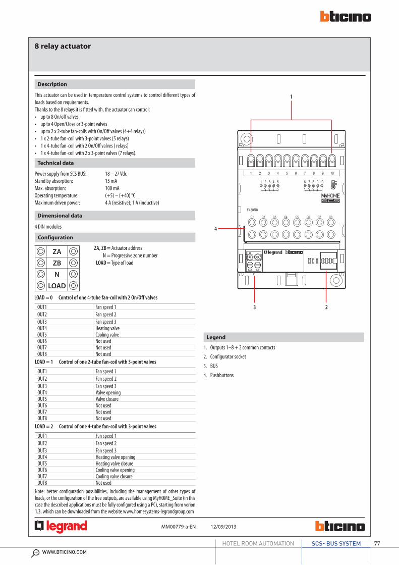
77WWW.BTICINO.COM
SCS- BUS SYSTEMHOTEL ROOM AUTOMATION
F430R8
MM00779-a-
1
3 2
4
12/09/2013EN
8 relay actuator
Legend
1. Outputs 1–8 + 2 common contacts2. Configurator socket3. BUS4. Pushbuttons
This actuator can be used in temperature control systems to control different types of loads based on requirements.Thanks to the 8 relays it is fitted with, the actuator can control:
up to 8 On/off valvesup to 4 Open/Close or 3-point valvesup to 2 x 2-tube fan-coils with On/Off valves (4+4 relays)1 x 2-tube fan-coil with 3-point valves (5 relays)1 x 4-tube fan-coil with 2 On/Off valves ( relays)1 x 4-tube fan-coil with 2 x 3-point valves (7 relays).
Description
Power supply from SCS BUS: 18 – 27 VdcStand by absorption: 15 mA Max. absorption: 100 mA Operating temperature: (+5) – (+40) °CMaximum driven power: 4 A (resistive); 1 A (inductive)
Technical data
4 DIN modules
Dimensional data
ZA, ZB = Actuator address N = Progressive zone number LOAD = Type of load
Configuration
ZA
ZB
N
LOAD
LOAD = 0 Control of one 4-tube fan-coil with 2 On/Off valvesOUT1 Fan speed 1OUT2 Fan speed 2OUT3 Fan speed 3OUT4 Heating valveOUT5 Cooling valveOUT6 Not usedOUT7 Not usedOUT8 Not used
OUT1 Fan speed 1OUT2 Fan speed 2OUT3 Fan speed 3OUT4 Valve openingOUT5 Valve closureOUT6 Not usedOUT7 Not usedOUT8 Not used
LOAD = 1 Control of one 2-tube fan-coil with 3-point valves
OUT1 Fan speed 1OUT2 Fan speed 2OUT3 Fan speed 3OUT4 Heating valve openingOUT5 Heating valve closureOUT6 Cooling valve openingOUT7 Cooling valve closureOUT8 Not used
LOAD = 2 Control of one 4-tube fan-coil with 3-point valves
Note: better configuration possibilities, including the management of other types of loads, or the configuration of the free outputs, are available using MyHOME_Suite (in this case the described applications must be fully configured using a PC), starting from verion 1.3, which can be downloaded from the website www.homesystems-legrandgroup.com

TECHNICAL SHEETS
78
MM00779-a-
M
OUT 3
OUT 2
OUT 1
N
L1 L2
F430R8
OUT 5
OUT 4
OUT 3OUT 2OUT 1
OUT 5OUT 4
L
N
230 Vac
F430R88 relay actuator
Wiring diagrams
Example of connection of a 4-tube fan-coil with On/Off valves.
F430R8
EN 30/09/2013

79WWW.BTICINO.COM
SCS- BUS SYSTEMHOTEL ROOM AUTOMATION
F430R3V10
12/09/2013MM00781-a-
2
8 7
5 5
6 6
3 41
Fan-coil actuator with 0-10 V valves
EN
Legend
1. Common contact2. Fan-coil fan speed3. Output H 0-10 V heating4. Output C 0-10 V cooling5. Pushbuttons for the complete opening/closure of the valves, and for changing the
fan speed6. LED7. Configurator socket8. BUS
DIN modularity actuator to be used in temperature control systems for the control of 2-tube or 4-tube fan coils with 0-10 V valvesIt has with 3 relays for the managementof the fan-coil fan, and 2 x 0-10 V outputs for the control of the valves.In systems with 2-tube fan-coils the H output is used both for heating and cooling.In systems with 4-tube fan-coils the H output must be used to control the heating valve, while the C output for the cooling valve.The LEDs indicate respectively the status of the valves and the active speed of the fan-coil fan.
Description
Power supply from SCS BUS: 18 – 27 VdcStand by absorption: 20 mAMax. absorption: 60 mAOperating temperature: (+5) – (+40) °CMaximum current supplied by each 0-10 V output: 1 mAMaximum driven power for the relays: 4A (resistive); 1A (inductive)
Technical data
4 DIN modules
Dimensional data
ZA, ZB = Actuator address N = Progressive zone number LOAD = Type of load
LOAD = 0; control of one 4-tube fan-coil with 0-10 V valves LOAD = 1; Control of one 2-tube fan-coil with 0-10 V valves
Configuration
ZA
ZB
N
LOAD
Virtual configuration using the MyHOME_Suite software:
The device can be configured remotely only if not already physically configured. The configuration is completed using version 1.3 or higher of the MyHOME_Suite software, which can be downloaded from the website www.homesystems-legrandgroup.com.

TECHNICAL SHEETS
80
12/09/2013MM00781-a-EN
F430R3V10Fan-coil actuator with 0-10 V valves
M
OUT 3
OUT 2
OUT 1
N
L1
OUT 3OUT 2OUT 1
L
N
230 Vac
F430R3V10+–
+–
78
56
M
M
0 – 10 V
0 – 10 V
Wiring diagrams
Example of connection of a 4-tube fan-coil with 0-10 V valves.
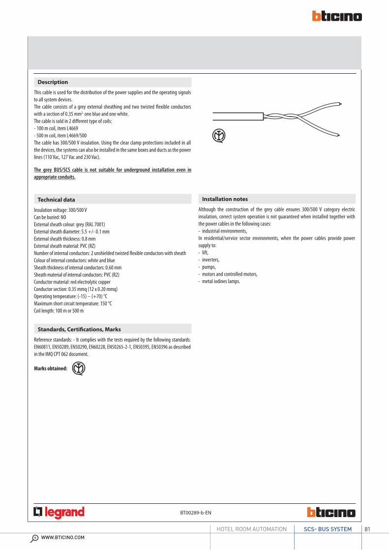
81WWW.BTICINO.COM
SCS- BUS SYSTEMHOTEL ROOM AUTOMATION
Description
This cable is used for the distribution of the power supplies and the operating signals to all system devices.The cable consists of a grey external sheathing and two twisted flexible conductors with a section of 0.35 mm2, one blue and one white. The cable is sold in 2 different type of coils:- 100 m coil, item L4669- 500 m coil, item L4669/500The cable has 300/500 V insulation. Using the clear clamp protections included in all the devices, the systems can also be installed in the same boxes and ducts as the power lines (110 Vac, 127 Vac and 230 Vac).
Installation notes
Although the construction of the grey cable ensures 300/500 V category electric insulation, correct system operation is not guaranteed when installed together with the power cables in the following cases:- industrial environments,In residential/service sector environments, when the power cables provide power supply to:- lift,- inverters,- pumps,- motors and controlled motors,- metal iodines lamps.
Technical data
Insulation voltage: 300/500 VCan be buried: NOExternal sheath colour: grey (RAL 7001)External sheath diameter: 5.5 +/- 0.1 mmExternal sheath thickness: 0.8 mmExternal sheath material: PVC (RZ)Number of internal conductors: 2 unshielded twisted flexible conductors with sheathColour of internal conductors: white and blueSheath thickness of internal conductors: 0.60 mmSheath material of internal conductors: PVC (R2)Conductor material: red electrolytic copperConductor section: 0.35 mmq (12 x 0.20 mmq)Operating temperature: (-15) – (+70) °CMaximum short circuit temperature: 150 °CCoil length: 100 m or 500 m
The grey BUS/SCS cable is not suitable for underground installation even in appropriate conduits.
BT00289-b-EN
L4669 - L4669/500BUS/SCS cable (grey)
Standards, Certifications, Marks
Reference standards: - It complies with the tests required by the following standards: EN60811, EN50289, EN50290, EN60228, EN50265-2-1, EN50395, EN50396 as described in the IMQ CPT 062 document.
Marks obtained:
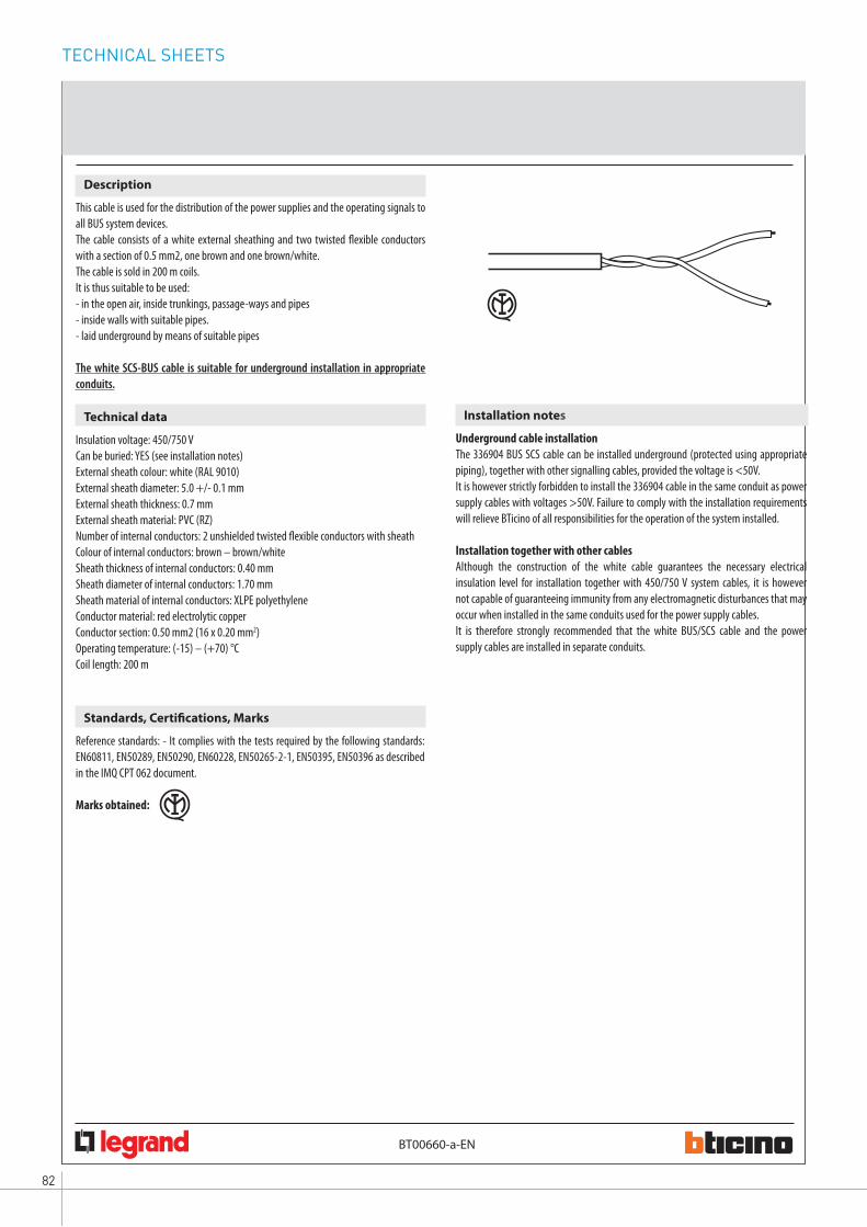
TECHNICAL SHEETS
82
BT00660-a-EN
336904A/V SCS/BUS cable (white)
Description
This cable is used for the distribution of the power supplies and the operating signals to all BUS system devices.The cable consists of a white external sheathing and two twisted flexible conductors with a section of 0.5 mm2, one brown and one brown/white. The cable is sold in 200 m coils.It is thus suitable to be used:- in the open air, inside trunkings, passage-ways and pipes- inside walls with suitable pipes.- laid underground by means of suitable pipes
The white SCS-BUS cable is suitable for underground installation in appropriate conduits.
Standards, Certifications, Marks
Reference standards: - It complies with the tests required by the following standards: EN60811, EN50289, EN50290, EN60228, EN50265-2-1, EN50395, EN50396 as described in the IMQ CPT 062 document.
Marks obtained:
Technical data
Insulation voltage: 450/750 VCan be buried: YES (see installation notes)External sheath colour: white (RAL 9010)External sheath diameter: 5.0 +/- 0.1 mmExternal sheath thickness: 0.7 mmExternal sheath material: PVC (RZ)Number of internal conductors: 2 unshielded twisted flexible conductors with sheathColour of internal conductors: brown – brown/whiteSheath thickness of internal conductors: 0.40 mmSheath diameter of internal conductors: 1.70 mmSheath material of internal conductors: XLPE polyethyleneConductor material: red electrolytic copperConductor section: 0.50 mm2 (16 x 0.20 mm2)Operating temperature: (-15) – (+70) °CCoil length: 200 m
Installation notes
Underground cable installationThe 336904 BUS SCS cable can be installed underground (protected using appropriate piping), together with other signalling cables, provided the voltage is <50V.It is however strictly forbidden to install the 336904 cable in the same conduit as power supply cables with voltages >50V. Failure to comply with the installation requirements will relieve BTicino of all responsibilities for the operation of the system installed.
Installation together with other cablesAlthough the construction of the white cable guarantees the necessary electrical insulation level for installation together with 450/750 V system cables, it is however not capable of guaranteeing immunity from any electromagnetic disturbances that may occur when installed in the same conduits used for the power supply cables. It is therefore strongly recommended that the white BUS/SCS cable and the power supply cables are installed in separate conduits.
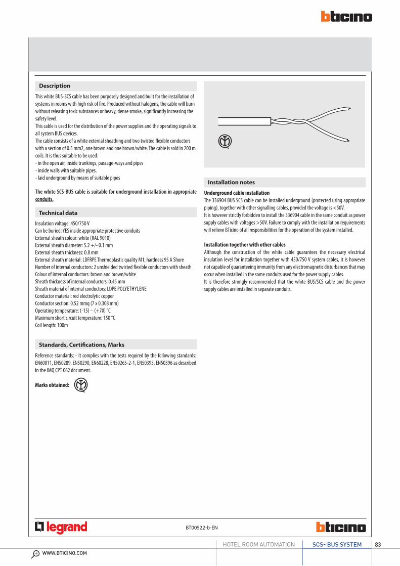
83WWW.BTICINO.COM
SCS- BUS SYSTEMHOTEL ROOM AUTOMATION
BT00522-b-EN
L4669HFHalogen free A/V SCS/BUS cable (white)
Description
This white BUS-SCS cable has been purposely designed and built for the installation of systems in rooms with high risk of fire. Produced without halogens, the cable will burn without releasing toxic substances or heavy, dense smoke, significantly increasing the safety level.This cable is used for the distribution of the power supplies and the operating signals to all system BUS devices. The cable consists of a white external sheathing and two twisted flexible conductors with a section of 0.5 mm2, one brown and one brown/white. The cable is sold in 200 m coils. It is thus suitable to be used:- in the open air, inside trunkings, passage-ways and pipes- inside walls with suitable pipes.- laid underground by means of suitable pipes
The white SCS-BUS cable is suitable for underground installation in appropriate conduits.
Standards, Certifications, Marks
Reference standards: - It complies with the tests required by the following standards: EN60811, EN50289, EN50290, EN60228, EN50265-2-1, EN50395, EN50396 as described in the IMQ CPT 062 document.
Marks obtained:
Technical data
Insulation voltage: 450/750 VCan be buried: YES inside appropriate protective conduitsExternal sheath colour: white (RAL 9010)External sheath diameter: 5.2 +/- 0.1 mmExternal sheath thickness: 0.8 mmExternal sheath material: LDFRPE Thermoplastic quality M1, hardness 95 A ShoreNumber of internal conductors: 2 unshielded twisted flexible conductors with sheathColour of internal conductors: brown and brown/whiteSheath thickness of internal conductors: 0.45 mmSheath material of internal conductors: LDPE POLYETHYLENE Conductor material: red electrolytic copperConductor section: 0.52 mmq (7 x 0.308 mm)Operating temperature: (-15) – (+70) °CMaximum short circuit temperature: 150 °CCoil length: 100m
Installation notes
Underground cable installationThe 336904 BUS SCS cable can be installed underground (protected using appropriate piping), together with other signalling cables, provided the voltage is <50V.It is however strictly forbidden to install the 336904 cable in the same conduit as power supply cables with voltages >50V. Failure to comply with the installation requirements will relieve BTicino of all responsibilities for the operation of the system installed.
Installation together with other cablesAlthough the construction of the white cable guarantees the necessary electrical insulation level for installation together with 450/750 V system cables, it is however not capable of guaranteeing immunity from any electromagnetic disturbances that may occur when installed in the same conduits used for the power supply cables. It is therefore strongly recommended that the white BUS/SCS cable and the power supply cables are installed in separate conduits.

84
NOTE
85WWW.BTICINO.COM
SCS- BUS SYSTEMHOTEL ROOM AUTOMATION
NOTE

86
NOTE


AD-E
XOD
14SA
G/G
B -
Ver
sion
02/
2014
BTi
cino
SpA
rese
rves
at a
ny ti
me
the
right
to m
odify
the
cont
ents
of t
his
book
let a
nd to
com
mun
icat
e,
in a
ny fo
rm a
nd m
odal
ity, t
he c
hang
es b
roug
ht to
the
sam
e.
BTicino SpAViale Borri, 23121100 Varese - Italywww.bticino.com