Embed Size (px)
Citation preview
FRIMEDA TPA INST_TPA 11/13
Assembly Instructions • Montageanleitung • Notice d‘utilisation
FRIMEDA TPA Lifting anchorFRIMEDA TPA TransportankerAncres de levage FRIMEDA TPA
Anchor load class
Load group of recess former
and ring clutchLoad group colour
0.7
1.4
2.0
2.5
2.5 orange
3.0
4.0
5.0
5.0 black
7.5
10.010.0 green
12.5
14.0
17.0
22.0
26.0
26.0 blue
2 © 2014 HALFEN · INST_TPA 11/13 · www.halfen.com
FRIMEDA TPA Assembly InstructionsD
euts
chEn
glis
hFr
ança
is
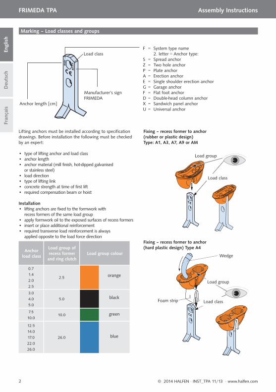
Marking – Load classes and groups
Manufacturer‘s signFRIMEDA
Anchor length [cm]
Load classF = System type name 2. letter = Anchor type:S = Spread anchorZ = Two hole anchorP = Plate anchorA = Erection anchorE = Single shoulder erection anchorG = Garage anchorF = Flat foot anchorD = Double-head column anchorX = Sandwich panel anchorU = Universal anchor
Lifting anchors must be installed according to specifi cation drawings. Before installation the following must be checked by an expert:
• type of lifting anchor and load class• anchor length• anchor material (mill finish, hot-dipped galvanised
or stainless steel)• load direction• type of lifting link• concrete strength at time of first lift• required compensation beam or hoist
Installation • lifting anchors are fixed to the formwork with
recess formers of the same load group• apply formwork oil to the exposed surfaces of recess formers • insert or place additional reinforcement • required transverse load reinforcement is always
applied opposite to the load force direction
Load group
Load class
Load group
Wedge
Foam strip Load class
Fixing – recess former to anchor(rubber or plastic design)Type: A1, A3, A7, A9 or AM
Fixing – recess former to anchor (hard plastic design) Type A4
90°
3© 2014 HALFEN · INST_TPA 11/13 · www.halfen.com
FRIMEDA TPA Assembly Instructions
Deu
tsch
Engl
ish
Fran
çais
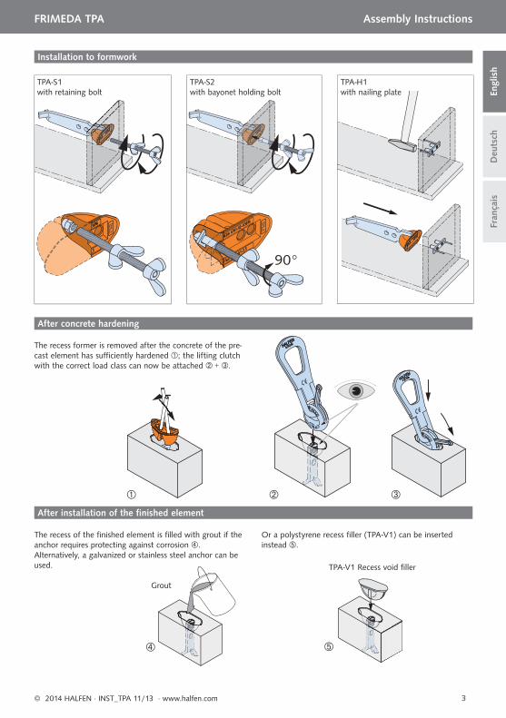
Installation to formwork
TPA-S1with retaining bolt
TPA-S2with bayonet holding bolt
TPA-H1with nailing plate
The recess former is removed after the concrete of the pre-cast element has suffi ciently hardened ; the lifting clutch with the correct load class can now be attached + .
The recess of the fi nished element is fi lled with grout if the anchor requires protecting against corrosion . Alternatively, a galvanized or stainless steel anchor can be used. TPA-V1 Recess void fi ller
Grout
After concrete hardening
After installation of the fi nished element
Or a polystyrene recess fi ller (TPA-V1) can be inserted instead .
α
30°- 60°
60°
4 © 2014 HALFEN · INST_TPA 11/13 · www.halfen.com
FRIMEDA TPA Assembly InstructionsD
euts
chEn
glis
hFr
ança
is
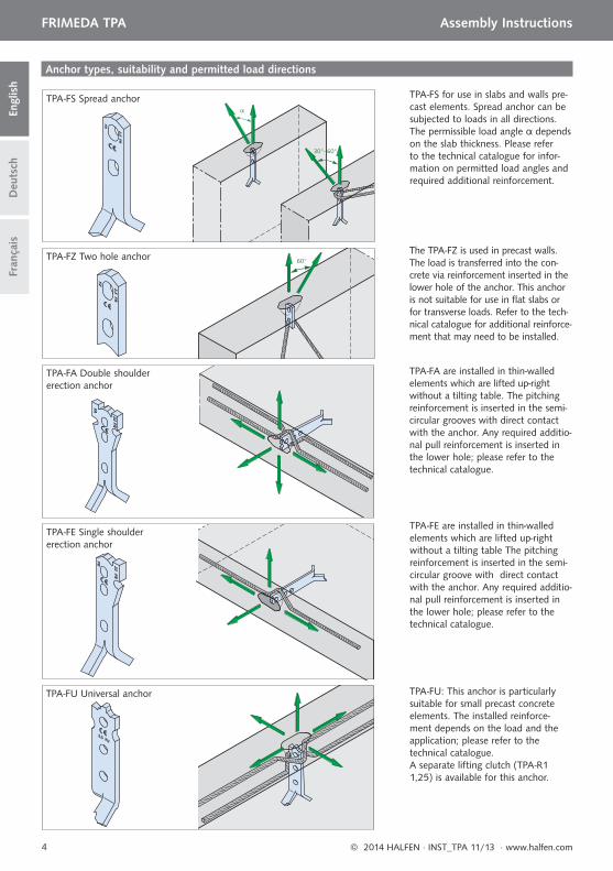
TPA-FS for use in slabs and walls pre-cast elements. Spread anchor can be subjected to loads in all directions. The permissible load angle α depends on the slab thickness. Please refer to the technical catalogue for infor-mation on permitted load angles and required additional reinforcement.
The TPA-FZ is used in precast walls. The load is transferred into the con-crete via reinforcement inserted in the lower hole of the anchor. This anchor is not suitable for use in fl at slabs or for transverse loads. Refer to the tech-nical catalogue for additional reinforce-ment that may need to be installed.
TPA-FA are installed in thin-walled elements which are lifted up-right without a tilting table. The pitching reinforcement is inserted in the semi-circular grooves with direct contact with the anchor. Any required additio-nal pull reinforcement is inserted in the lower hole; please refer to the technical catalogue.
TPA-FE are installed in thin-walled elements which are lifted up-right without a tilting table The pitching reinforcement is inserted in the semi-circular groove with direct contact with the anchor. Any required additio-nal pull reinforcement is inserted in the lower hole; please refer to the technical catalogue.
TPA-FS Spread anchor
TPA-FU: This anchor is particularly suitable for small precast concrete elements. The installed reinforce-ment depends on the load and the application; please refer to the technical catalogue.A separate lifting clutch (TPA-R1 1,25) is available for this anchor.
TPA-FZ Two hole anchor
TPA-FA Double shoulder erection anchor
TPA-FE Single shoulder erection anchor
TPA-FU Universal anchor
Anchor types, suitability and permitted load directions
30°
30°
60°
60°
5© 2014 HALFEN · INST_TPA 11/13 · www.halfen.com
FRIMEDA TPA Assembly Instructions
Deu
tsch
Engl
ish
Fran
çais
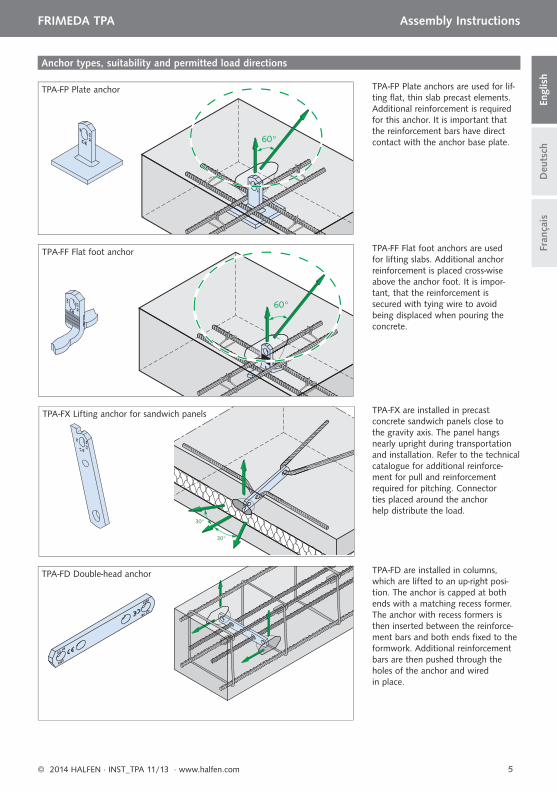
Anchor types, suitability and permitted load directions
TPA-FF Flat foot anchors are used for lifting slabs. Additional anchor reinforcement is placed cross-wise above the anchor foot. It is impor-tant, that the reinforcement is secured with tying wire to avoidbeing displaced when pouring the concrete.
TPA-FP Plate anchors are used for lif-ting fl at, thin slab precast elements. Additional reinforcement is required for this anchor. It is important that the reinforcement bars have direct contact with the anchor base plate.
TPA-FX are installed in precast concrete sandwich panels close to the gravity axis. The panel hangs nearly upright during transportation and installation. Refer to the technical catalogue for additional reinforce-ment for pull and reinforcement required for pitching. Connector ties placed around the anchor help distribute the load.
TPA-FX Lifting anchor for sandwich panels
TPA-FD are installed in columns, which are lifted to an up-right posi-tion. The anchor is capped at both ends with a matching recess former. The anchor with recess formers is then inserted between the reinforce-ment bars and both ends fi xed to the formwork. Additional reinforcement bars are then pushed through the holes of the anchor and wired in place.
TPA-FD Double-head anchor
TPA-FF Flat foot anchor
TPA-FP Plate anchor
Lastklasse der Anker
Lastgruppe der Aussparungs-körper und
Ringkupplung
Farbe der Lastgruppe
0,7
1,4
2,0
2,5
2,5 orange
3,0
4,0
5,0
5,0 schwarz
7,5
10,010,0
grün
12.5
14.0
17.0
22.0
26.0
26.0 blau
6 © 2014 HALFEN · INST_TPA 11/13 · www.halfen.com
Deu
tsch
Engl
ish
Fran
çais
FRIMEDA TPA Montageanleitung
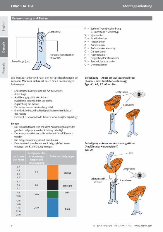
Kennzeichnung und Einbau
HerstellerkennzeichenFRIMEDA
Ankerlänge [cm]
LastklasseF = System-Typenbeschreibung 2. Buchstabe = Ankertyp:S = SpreizankerZ = ZweilochankerP = PlattenankerA = AufstellankerE = Aufstellanker einseitigG = GaragenankerF = FlachfußankerD = Doppelkopf-StützenankerX = SandwichplattenankerU = Universalanker
Die Transportanker sind nach den Fertigteilzeichnungen ein-zubauen. Vor dem Einbau ist durch einen Sachkundigen festzulegen:
• Erforderliche Laststufe und die Art des Ankers• Ankerlänge• Ausführungsqualität des Ankers (walzblank, verzinkt oder Edelstahl)• Zugrichtung des Ankers• Das zu verwendende Anschlagmittel• Erforderliche Betondruckfestigkeit beim ersten Belasten des Ankers• Eventuell zu verwendende Traverse oder Ausgleichsgehänge
Einbau • Der Transportanker wird mit dem Aussparungskörper der gleichen Lastgruppe an der Schalung befestigt• Der Aussparungskörper sollte außen mit Schalöl benetzt werden• Die Zulagebewehrung ist mit einzubauen• Den eventuell einzubauenden Schrägzugbügel immer entgegen der Kraftrichtung einlegen
Lastgruppe
Lastklasse
Lastgruppe
Keil
Schaumstoff -streifen
Lastklasse
Befestigung – Anker am Aussparungskörper(Gummi- oder Kunststoff ausführung)Typ: A1, A3, A7, A9 or AM
Befestigung – Anker am Aussparungskörper (Ausführung: Hartkunststoff )Typ: A4
90°
7© 2014 HALFEN · INST_TPA 11/13 · www.halfen.com
Deu
tsch
Engl
ish
Fran
çais
FRIMEDA TPA Montageanleitung
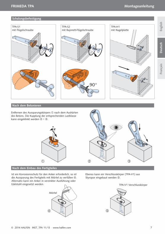
Schalungsbefestigung
TPA-S1mit Flügelschraube
TPA-S2mit Bajonett-Flügelschraube
TPA-H1mit Nagelplatte
Entfernen des Aussparungskörpers nach dem Aushärten des Betons. Die Kupplung der entsprechenden Lastklasse kann eingeklinkt werden + .
Ist ein Korrosionsschutz für den Anker erforderlich, so ist die Aussparung des Fertigteils mit Mörtel zu verfüllen . Alternativ kann ein Anker in verzinkter Ausführung oder Edelstahl eingesetzt werden. TPA-V1 Verschlusskörper
Mörtel
Nach dem Betonieren
Nach dem Einbau des Fertigteiles
Ebenso kann ein Verschlusskörper (TPA-V1) aus Styropor eingebaut werden .
α
30°- 60°
60°
8 © 2014 HALFEN · INST_TPA 11/13 · www.halfen.com
Deu
tsch
Engl
ish
Fran
çais
FRIMEDA TPA Montageanleitung
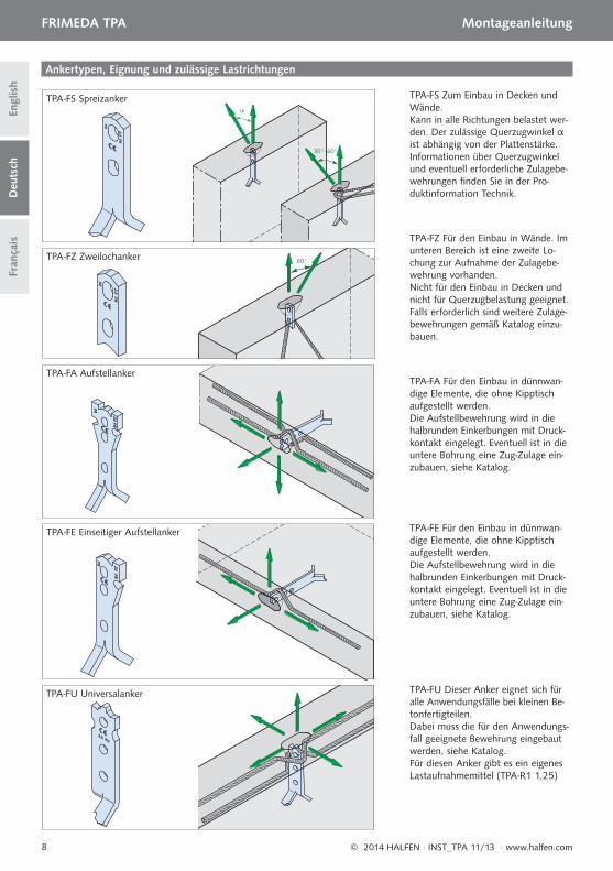
TPA-FS Zum Einbau in Decken und Wände.Kann in alle Richtungen belastet wer-den. Der zulässige Querzugwinkel α ist abhängig von der Plattenstärke. Informationen über Querzugwinkel und eventuell erforderliche Zulagebe-wehrungen fi nden Sie in der Pro-duktinformation Technik.
TPA-FZ Für den Einbau in Wände. Im unteren Bereich ist eine zweite Lo-chung zur Aufnahme der Zulagebe-wehrung vorhanden. Nicht für den Einbau in Decken und nicht für Querzugbelastung geeignet.Falls erforderlich sind weitere Zulage-bewehrungen gemäß Katalog einzu-bauen.
TPA-FA Für den Einbau in dünnwan-dige Elemente, die ohne Kipptisch aufgestellt werden.Die Aufstellbewehrung wird in die halbrunden Einkerbungen mit Druck-kontakt eingelegt. Eventuell ist in die untere Bohrung eine Zug-Zulage ein-zubauen, siehe Katalog.
TPA-FE Für den Einbau in dünnwan-dige Elemente, die ohne Kipptisch aufgestellt werden. Die Aufstellbewehrung wird in die halbrunden Einkerbungen mit Druck-kontakt eingelegt. Eventuell ist in die untere Bohrung eine Zug-Zulage ein-zubauen, siehe Katalog.
TPA-FS Spreizanker
TPA-FU Dieser Anker eignet sich für alle Anwendungsfälle bei kleinen Be-tonfertigteilen. Dabei muss die für den Anwendungs-fall geeignete Bewehrung eingebaut werden, siehe Katalog. Für diesen Anker gibt es ein eigenes Lastaufnahmemittel (TPA-R1 1,25)
TPA-FZ Zweilochanker
TPA-FE Einseitiger Aufstellanker
TPA-FA Aufstellanker
TPA-FU Universalanker
Ankertypen, Eignung und zulässige Lastrichtungen
30°
30°
60°
60°
9© 2014 HALFEN · INST_TPA 11/13 · www.halfen.com
Deu
tsch
Engl
ish
Fran
çais
FRIMEDA TPA Montageanleitung
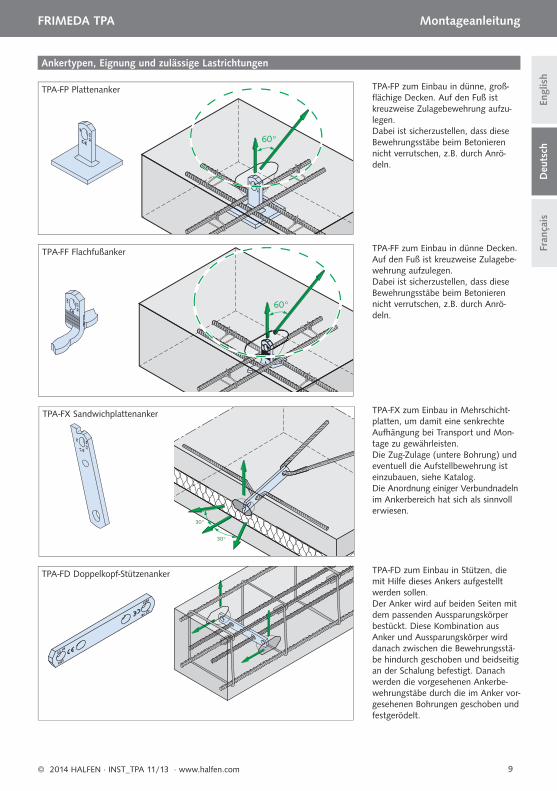
Ankertypen, Eignung und zulässige Lastrichtungen
TPA-FF zum Einbau in dünne Decken. Auf den Fuß ist kreuzweise Zulagebe-wehrung aufzulegen. Dabei ist sicherzustellen, dass diese Bewehrungsstäbe beim Betonieren nicht verrutschen, z.B. durch Anrö-deln.
TPA-FP zum Einbau in dünne, groß-fl ächige Decken. Auf den Fuß ist kreuzweise Zulagebewehrung aufzu-legen. Dabei ist sicherzustellen, dass diese Bewehrungsstäbe beim Betonieren nicht verrutschen, z.B. durch Anrö-deln.
TPA-FX zum Einbau in Mehrschicht-platten, um damit eine senkrechte Aufhängung bei Transport und Mon-tage zu gewährleisten. Die Zug-Zulage (untere Bohrung) und eventuell die Aufstellbewehrung ist einzubauen, siehe Katalog. Die Anordnung einiger Verbundnadeln im Ankerbereich hat sich als sinnvoll erwiesen.
TPA-FX Sandwichplattenanker
TPA-FD zum Einbau in Stützen, die mit Hilfe dieses Ankers aufgestellt werden sollen. Der Anker wird auf beiden Seiten mit dem passenden Aussparungskörper bestückt. Diese Kombination aus Anker und Aussparungskörper wird danach zwischen die Bewehrungsstä-be hindurch geschoben und beidseitig an der Schalung befestigt. Danach werden die vorgesehenen Ankerbe-wehrungstäbe durch die im Anker vor-gesehenen Bohrungen geschoben und festgerödelt.
TPA-FD Doppelkopf-Stützenanker
TPA-FF Flachfußanker
TPA-FP Plattenanker
Forces portante de l’ancre
Catégories de la réservation et an-neau de levage
couleur
0.7
1.4
2.0
2.5
2.5 orange
3.0
4.0
5.0
5.0noir
7.5
10.010.0 vert
12.5
14.0
17.0
22.0
26.0
26.0 bleu
10 © 2014 HALFEN · INST_TPA 11/13 · www.halfen.com
Deu
tsch
Engl
ish
Fran
çais
FRIMEDA TPA Notice d‘utilisation
Marquage et mise en place
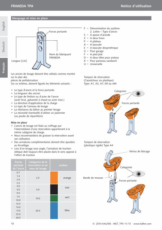
Nom du fabriquantFRIMEDA
Longeur [cm]
Forces portante F = Dénomination du système 2. Lettre = Type d‘ancre:S = A queue d‘arondeZ = A deux trousP = A plateauA = A basculerE = A basculer dissymétriqueG = Pour garageF = A pied platD = A deux têtes pour poteauX = Pour panneau sandwichU = Universelle
Les ancres de levage doivent être utilisée comme montré sur le plan des pièces de préfabrication.Sur ce schéma, doivent fi gurés les éléments suivants :
• Le type d’ancre et la force portante• La longueur des ancres• Le type de fi nition ou d’acier de l’ancre (acier brut, galvanisé à chaud ou acier inox.)• La direction d’application de la charge• Le type de l’anneau de levage• La résistance du béton au premier levage• La nécessité éventuelle d’utiliser un palonnier (ou poulie de répartition)
Mise en place • L’ancre de levage est fi xée au coff rage par l’intermédiaire d’une réservation appartenant à la même catégorie de charge.• Nous recommandons de graisser la réservation avant son utilisation.• Des armatures complémentaires doivent être ajoutées au ferraillage.• Lors d’un levage sous angle, l’armature de traction oblique doit toujours être placée dans le sens opposé à l’eff ort de traction
Categories
Forces portante
Forces portante
Categories
Vérrou de blocage
Bande de mousse
Tampon de réservation(Caoutchouc ou plastique)Type: A1, A3, A7, A9 ou AM
Tampon de réservation(plastique rigide) Type A4
90°
11© 2014 HALFEN · INST_TPA 11/13 · www.halfen.com
Deu
tsch
Engl
ish
Fran
çais
FRIMEDA TPA Notice d‘utilisation
Fixation du tampon de réservation
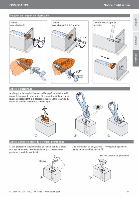
TPA-S1avec vis d’arrêt
TPA-S2avec vis d’arrêt à baïonnette
TPA-H1 avec plaque de maintien
Si une protection supplémentaire de l’ancre contre la corro-sion est nécessaire, l‘évidement laissé par la réservation peut être rempli de mortier.
TPA-V1 tampon de protection
Mortier
Après le bétonnage
Après la mise en place de l‘élément préfabriqué
Une réservation en polystyrène (TPAV1) peut également permettre de combler ce vide.
Après que le béton de l‘élément préfabriqué est durci, on dé-moule le tampon de réservation et on introduit l’anneau de levage correspondant à la catégorie d’ancre ,dans la cavité du béton en fermant le verrou à la main +
α
30°- 60°
60°
12 © 2014 HALFEN · INST_TPA 11/13 · www.halfen.com
Deu
tsch
Engl
ish
Fran
çais
FRIMEDA TPA Notice d‘utilisation
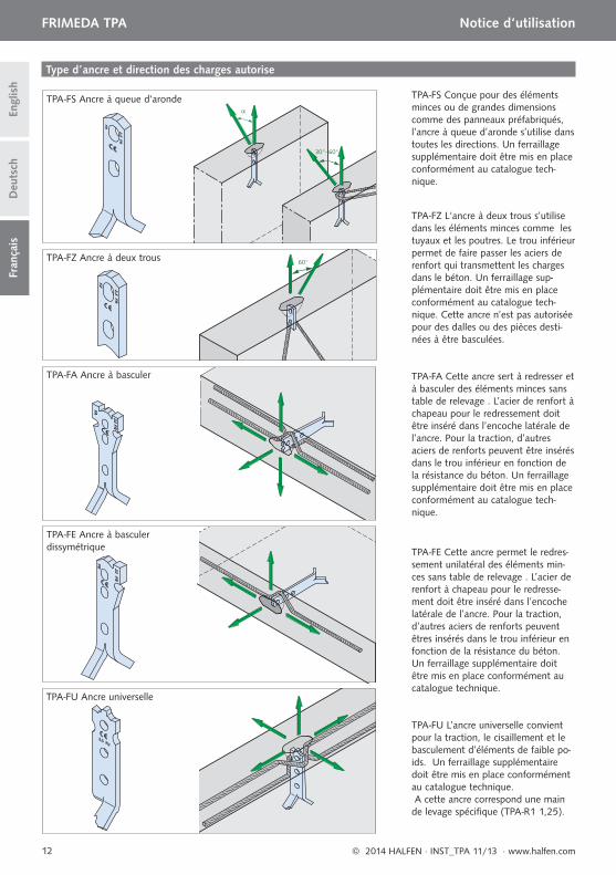
TPA-FZ L‘ancre à deux trous s’utilise dans les éléments minces comme les tuyaux et les poutres. Le trou inférieur permet de faire passer les aciers de renfort qui transmettent les charges dans le béton. Un ferraillage sup-plémentaire doit être mis en place conformément au catalogue tech-nique. Cette ancre n’est pas autorisée pour des dalles ou des pièces desti-nées à être basculées.
TPA-FA Cette ancre sert à redresser et à basculer des éléments minces sans table de relevage . L’acier de renfort à chapeau pour le redressement doit être inséré dans l’encoche latérale de l’ancre. Pour la traction, d’autres aciers de renforts peuvent être insérés dans le trou inférieur en fonction de la résistance du béton. Un ferraillage supplémentaire doit être mis en place conformément au catalogue tech-nique.
TPA-FE Cette ancre permet le redres-sement unilatéral des éléments min-ces sans table de relevage . L’acier de renfort à chapeau pour le redresse-ment doit être inséré dans l’encoche latérale de l’ancre. Pour la traction, d’autres aciers de renforts peuvent êtres insérés dans le trou inférieur en fonction de la résistance du béton. Un ferraillage supplémentaire doit être mis en place conformément au catalogue technique.
TPA-FU L’ancre universelle convient pour la traction, le cisaillement et le basculement d’éléments de faible po-ids. Un ferraillage supplémentaire doit être mis en place conformément au catalogue technique. A cette ancre correspond une main de levage spécifi que (TPA-R1 1,25).
TPA-FS Ancre à queue d‘aronde
TPA-FZ Ancre à deux trous
TPA-FA Ancre à basculer
TPA-FE Ancre à basculer dissymétrique
TPA-FU Ancre universelle
Type d’ancre et direction des charges autorise
TPA-FS Conçue pour des éléments minces ou de grandes dimensions comme des panneaux préfabriqués, l’ancre à queue d’aronde s’utilise dans toutes les directions. Un ferraillage supplémentaire doit être mis en place conformément au catalogue tech-nique.
30°
30°
45°
45°
13© 2014 HALFEN · INST_TPA 11/13 · www.halfen.com
Deu
tsch
Engl
ish
Fran
çais
FRIMEDA TPA Notice d‘utilisation
Type d’ancre et direction des charges autorise
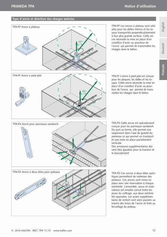
TPA-FF L’ancre à pied plat est conçue pour les plaques, les dalles et les tu-yaux. Cette ancre nécessite la mise en place d’un croisillon d’acier au pour-tour de l’ancre qui permet de trans-mettre les charges dans le béton.
TPA-FP Les ancres à plateau sont utili-sées pour les dalles minces et les tu-yaux transportés perpendiculairement à leur plus grande surface. Cette an-cre nécessite la mise en place d’un croisillon d’acier au pourtour de l’ancre qui permet de transmettre les charges dans le béton.
TPA-FX Cette ancre est spécialement conçue pour les panneaux sandwich. De part sa forme, elle permet une suspension dans l’axe de gravité du panneau ce qui permet un transport et une mise en place parfaitement verticale.Des armatures supplémentaires doi-vent être ajoutées pour la traction et le basculement
TPA-FX Ancre pour panneaux sandwich
TPA-FD Ces ancres à deux têtes spéci-fi ques permettent de redresser des poteaux. Ces ancres sont mises en place avec une réservation à chaque extrémité. L’ensemble, ancre et réser-vations est ensuite coincé entre les joues du coff rage, aux deux extrémi-tés opposées. Les aciers supplémen-taires de renfort sont alors passées au travers des trous de l’ancre et fi xés au ferraillage du poteau.
TPA-FD Ancre à deux têtes pour poteaux
TPA-FF Ancre à pied plat
TPA-FP Ancre à plateau

14 © 2014 HALFEN · INST_TPA 11/13 · www.halfen.com
NOTES REGARDING THIS DOCUMENTTechnical and design changes reserved. The information in this publication is based on state-of-the-art technology at the time of publication. We reserve the right to make technical and design changes at any time. Halfen GmbH shall not accept liability for the accuracy of the information in this publication or for any printing errors.
The Quality Management System of Halfen GmbH is certifi ed for the locations in Germany, France, the Netherlands, Austria, Poland, Switzerland and the Czech Republic acc. to DIN EN ISO 9001:2008, Certifi cate No. QS-281 HH.
Furthermore HALFEN is represented with sales offi ces and distributors worldwide. Please contact us: www.halfen.com
Austria HALFEN Gesellschaft m.b.H.Leonard-Bernstein-Str. 101220 Wien
Phone: +43 - 1 - 259 6770 E-Mail: offi [email protected]: www.halfen.at
Fax: +43 - 1 - 259 - 6770 99
Belgium /Luxembourg
HALFEN N.V.Borkelstraat 1312900 Schoten
Phone: +32 - 3 - 658 07 20E-Mail: [email protected]: www.halfen.be
Fax: +32 - 3 - 658 15 33
China HALFEN Construction Accessories Distribution Co.Ltd.Room 601 Tower D, Vantone CentreNo.A6 Chao Yang Men Wai StreetChaoyang District Beijing · P.R. China 100020
Phone: +86 - 10 5907 3200E-Mail: [email protected]: www.halfen.cn
Fax: +86 - 10 5907 3218
Czech Republic HALFEN-DEHA s.r.o.Business Center ŠafránkovaŠafránkova 1238/1155 00 Praha 5
Phone: +420 - 311 - 690 060E-Mail: [email protected]: www.halfen-deha.cz
Fax: +420 - 235 - 314308
France HALFEN S.A.S.18, rue Goubet75019 Paris
Phone: +33 - 1 - 445231 00E-Mail: [email protected]: www.halfen.fr
Fax: +33 - 1 - 445231 52
Germany HALFEN Vertriebsgesellschaft mbHKatzbergstrasse 3 40764 Langenfeld
Phone: +49 - 2173 - 970 0E-Mail: [email protected]: www.halfen.de
Fax: +49 - 2173 - 970 225
Italy HALFEN S.r.l. Soc. UnipersonaleVia F.lli Bronzetti N° 2824124 Bergamo
Phone: +39 - 035 - 0760711E-Mail: [email protected]: www.halfen.it
Fax: +39 - 035 - 0760799
Netherlands HALFEN b.v.Oostermaat 37623 CS Borne
Phone: +31 - 74-267 14 49E-Mail: [email protected]: www.halfen.nl
Fax: +31 - 74-2 67 26 59
Norway HALFEN ASPostboks 20804095 Stavanger
Phone: +47 - 51 82 34 00E-Mail: [email protected]: www.halfen.no
Fax: +47 - 51 82 34 01
Poland HALFEN Sp. z o.o.Ul. Obornicka 28760-691 Poznan
Phone: +48 - 61 - 622 14 14E-Mail: [email protected]: www.halfen.pl
Fax: +48 - 61 - 622 14 15
Sweden Halfen ABBox 150435 23 Mölnlycke
Phone: +46 - 31 - 98 58 00E-Mail: [email protected]: www.halfen.se
Fax: +46 - 31 - 98 58 01
Switzerland HALFEN Swiss AGHertistrasse 25 8304 Wallisellen
Phone: +41 - 44 - 849 78 78E-Mail: [email protected]: www.halfen.ch
Fax: +41 - 44 - 849 78 79
United Kingdom /Ireland
HALFEN Ltd.A1/A2 Portland CloseHoughton Regis LU5 5AW
Phone: +44 - 1582 - 47 03 00E-Mail: [email protected]: www.halfen.co.uk
Fax: +44 - 1582 - 47 03 04
United States of America
HALFEN USA Inc.8521 FM 1976P.O. Box 547Converse, TX 78109
Phone: +1 800.423.91 40E-Mail: [email protected]: www.halfenusa.com
Fax: +1 877 . 683.4910
For countries not listed HALFEN International
HALFEN International GmbHLiebigstr. 14 40764 Langenfeld / Germany
Phone: +49 - 2173 - 970 - 0 E-Mail: [email protected]: www.halfen.com
Fax: +49 - 2173 - 970 - 849
CONTACT HALFEN WORLDWIDE
HALFEN is represented by subsidiar ies in the fol lowing 14 countr ies, please contact us:

© 2
014
HA
LFEN
Gm
bH, G
erm
any
appl
ies
also
to
copy
ing
in e
xtra
cts.
252
U -
402
- 11/
13 P
DF-
4C
01/1
4


![SISTEMA DE ANCLAJES DE TRANSPORTE FRIMEDA de... · Grupo de carga embrague [t] Grupo de carga anclaje [t] Descripción del sistema El sistema de anclajes de transporte FRIMEDA consiste](https://img.dokumen.tips/doc/110x75/5babc2df09d3f2e74b8cbd18/sistema-de-anclajes-de-transporte-frimeda-de-grupo-de-carga-embrague-t.jpg)