Embed Size (px)
Citation preview
Frequency Agile Ferroelectric Filters,
Power Dividers, and Couplers
International Microwave Symposium 2009
R. Weigel and E. Lourandakis
Workshop
WMA
Outline
• Motivation
• Tunable Passive Components
– Ferroelectric Varactors
• Frequency Agile Filters
• Frequency Agile Power Dividers & Couplers
• Prototype Implementation & Results
• Reconfigurable Amplifier Concept
• Conclusion & Outlook
2
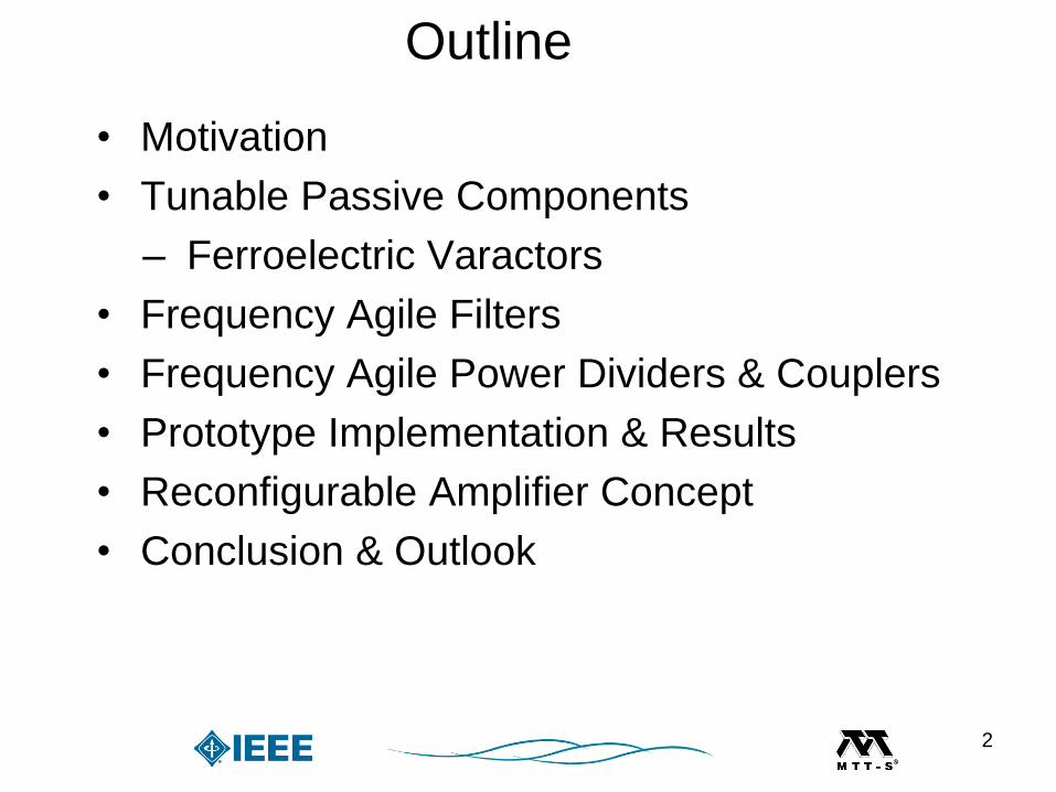
Motivation
• Increasing number of communication bands
• Additional wireless services, e.g. GPS, WiMAX
• Demand for reconfigurable front-end solutions
Motivation
3
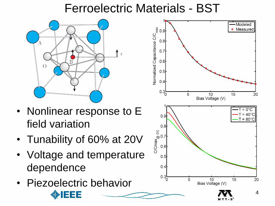
Ferroelectric Materials - BST
• Nonlinear response to E
field variation
• Tunability of 60% at 20V
• Voltage and temperature
dependence
• Piezoelectric behavior4
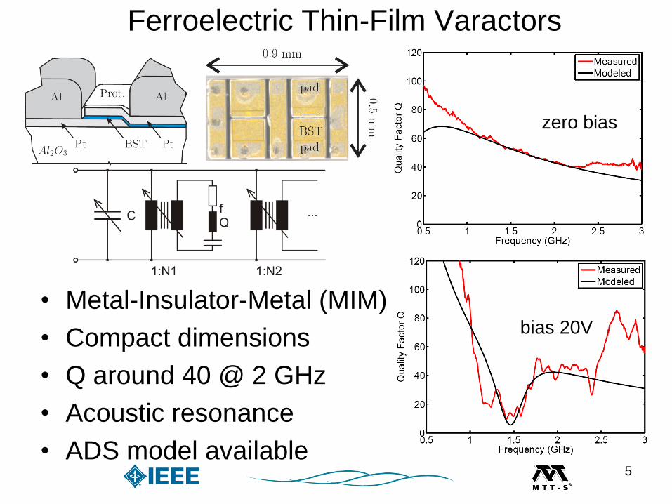
Ferroelectric Thin-Film Varactors
• Metal-Insulator-Metal (MIM)
• Compact dimensions
• Q around 40 @ 2 GHz
• Acoustic resonance
• ADS model available
zero bias
bias 20V
5
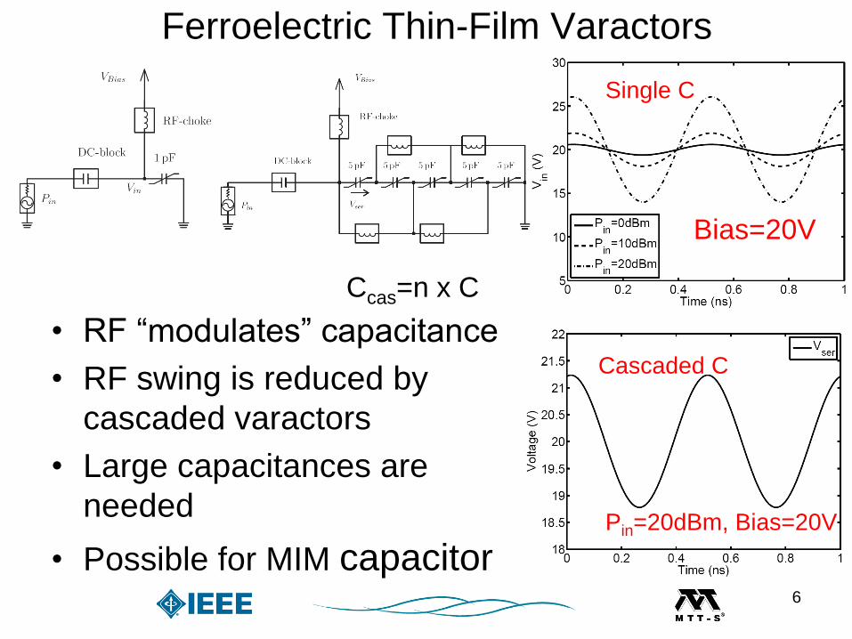
• RF “modulates” capacitance
• RF swing is reduced by
cascaded varactors
• Large capacitances are
needed
• Possible for MIM capacitor
Ccas=n x C
Single C
Cascaded C
Pin=20dBm, Bias=20V
Bias=20V
Ferroelectric Thin-Film Varactors
6

Analytical Filter Design – Lowpass
• Chebyshev lowpass filter
• Analytical formulas for
zero locations
7

Frequency Agile Lowpass
• Assumed tunability of 60% for BST varactors
• Multiband tuning from 1.5 – 2.3 GHz
• Changing C results in shifted zero locations
8
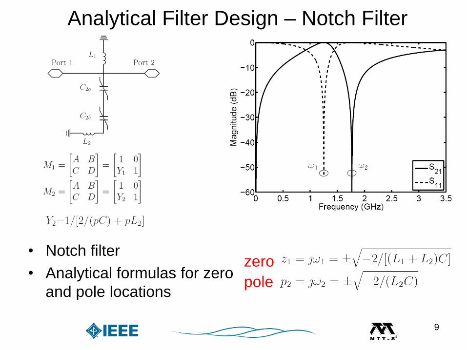
Analytical Filter Design – Notch Filter
zero
pole
• Notch filter
• Analytical formulas for zero
and pole locations
9

Frequency Agile Notch Filter
• Assumed tunability of 60% for BST varactors
• Multiband tuning from 1.7 – 2.7 GHz
• Changing C results in shifted zeros and poles
10
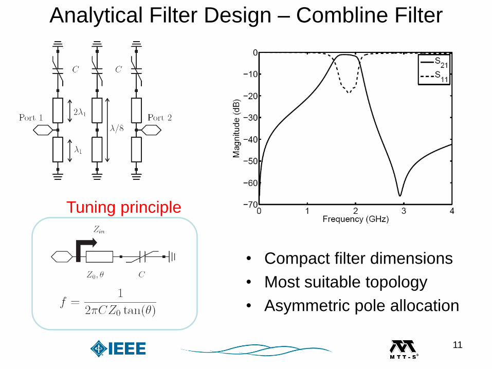
Analytical Filter Design – Combline Filter
• Compact filter dimensions
• Most suitable topology
• Asymmetric pole allocation
Tuning principle
11

Modified Combline Filter
• Second attenuation pole
is shifted from DC to
lower stopband
• Symmetric pass- to
stopband transition
OriginalModified
12
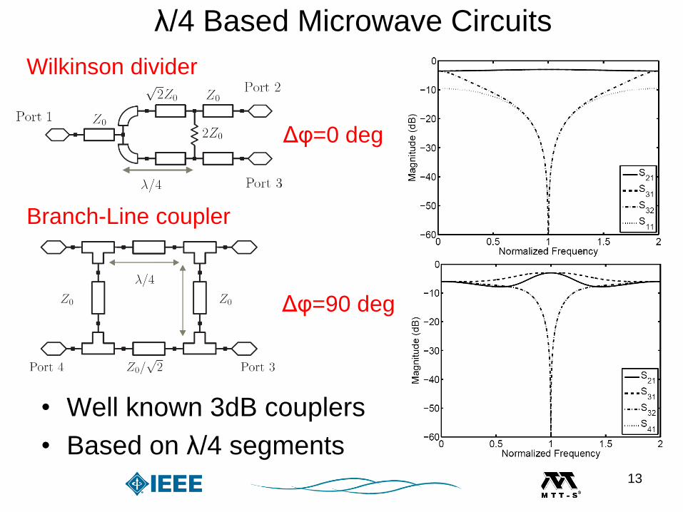
λ/4 Based Microwave Circuits
• Well known 3dB couplers
• Based on λ/4 segments
Δφ=0 deg
Δφ=90 deg
Wilkinson divider
Branch-Line coupler
13
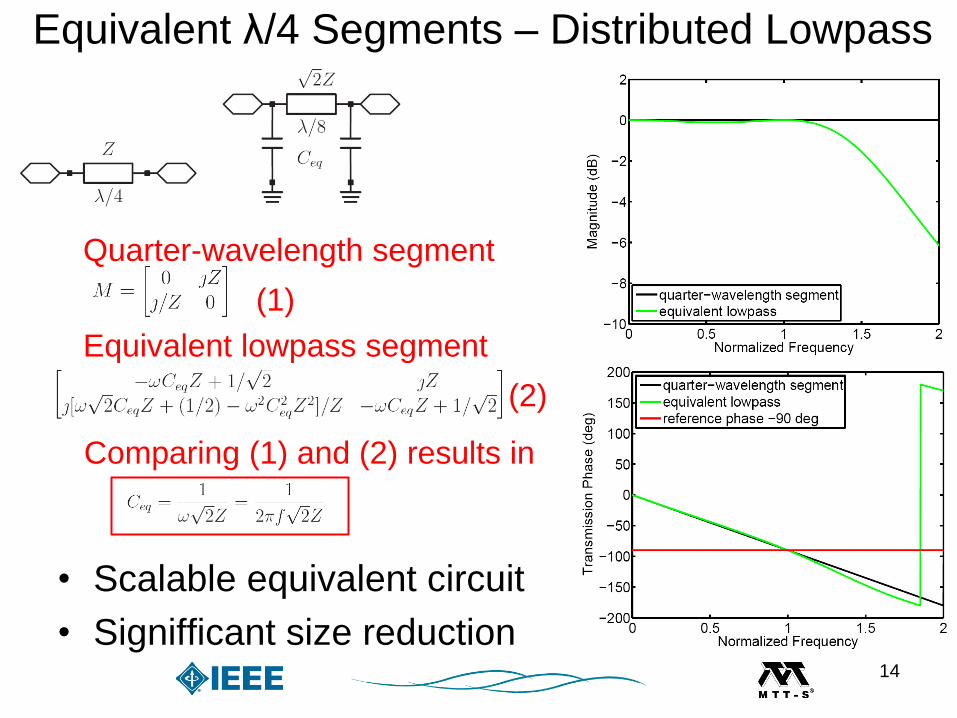
Equivalent λ/4 Segments – Distributed Lowpass
• Scalable equivalent circuit
• Signifficant size reduction
Quarter-wavelength segment
Equivalent lowpass segment
(1)
(2)
Comparing (1) and (2) results in
14
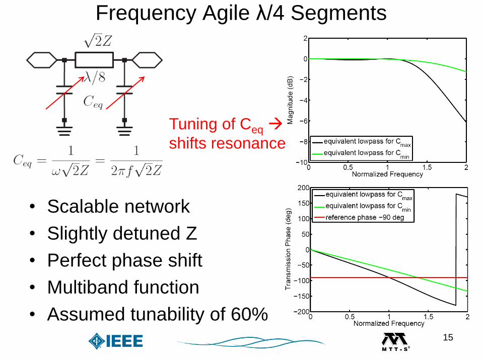
Frequency Agile λ/4 Segments
• Scalable network
• Slightly detuned Z
• Perfect phase shift
• Multiband function
• Assumed tunability of 60%
Tuning of Ceq
shifts resonance
15
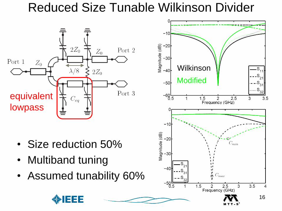
Reduced Size Tunable Wilkinson Divider
• Size reduction 50%
• Multiband tuning
• Assumed tunability 60%
equivalent
lowpass
Wilkinson
Modified
16
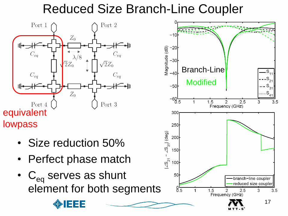
Reduced Size Branch-Line Coupler
• Size reduction 50%
• Perfect phase match
• Ceq serves as shunt
element for both segments
Branch-Line
Modified
equivalent
lowpass
17
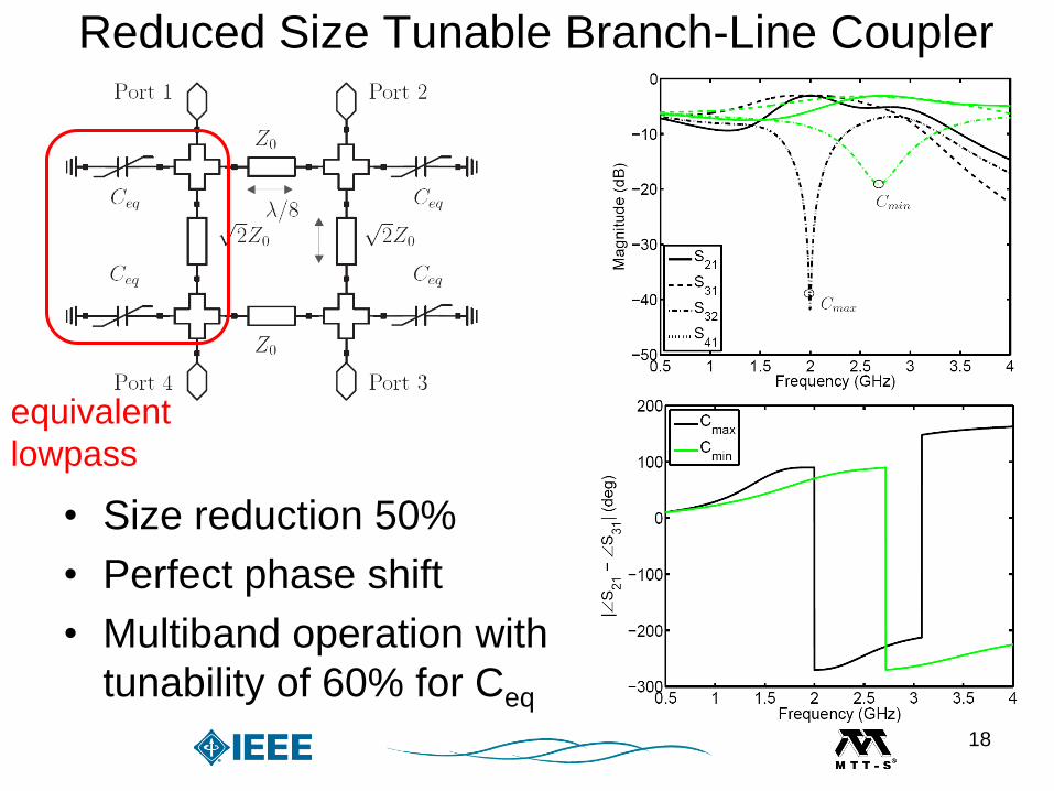
Reduced Size Tunable Branch-Line Coupler
• Size reduction 50%
• Perfect phase shift
• Multiband operation with
tunability of 60% for Ceq
equivalent
lowpass
18
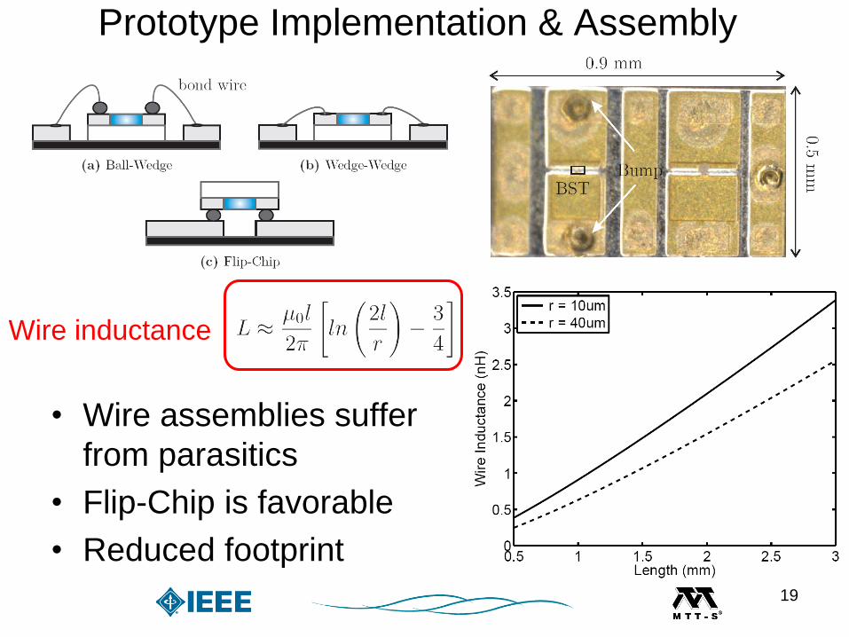
Prototype Implementation & Assembly
• Wire assemblies suffer
from parasitics
• Flip-Chip is favorable
• Reduced footprint
Wire inductance
19
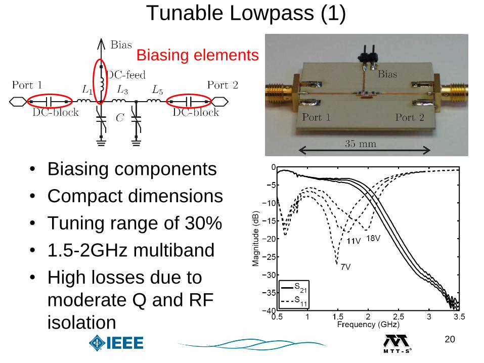
Tunable Lowpass (1)
• Biasing components
• Compact dimensions
• Tuning range of 30%
• 1.5-2GHz multiband
• High losses due to
moderate Q and RF
isolation
Biasing elements
20
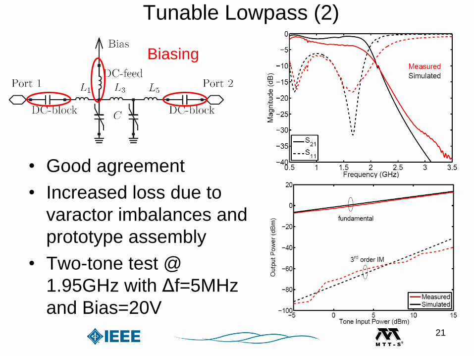
• Good agreement
• Increased loss due to
varactor imbalances and
prototype assembly
• Two-tone test @
1.95GHz with Δf=5MHz
and Bias=20V
Biasing
Tunable Lowpass (2)
21
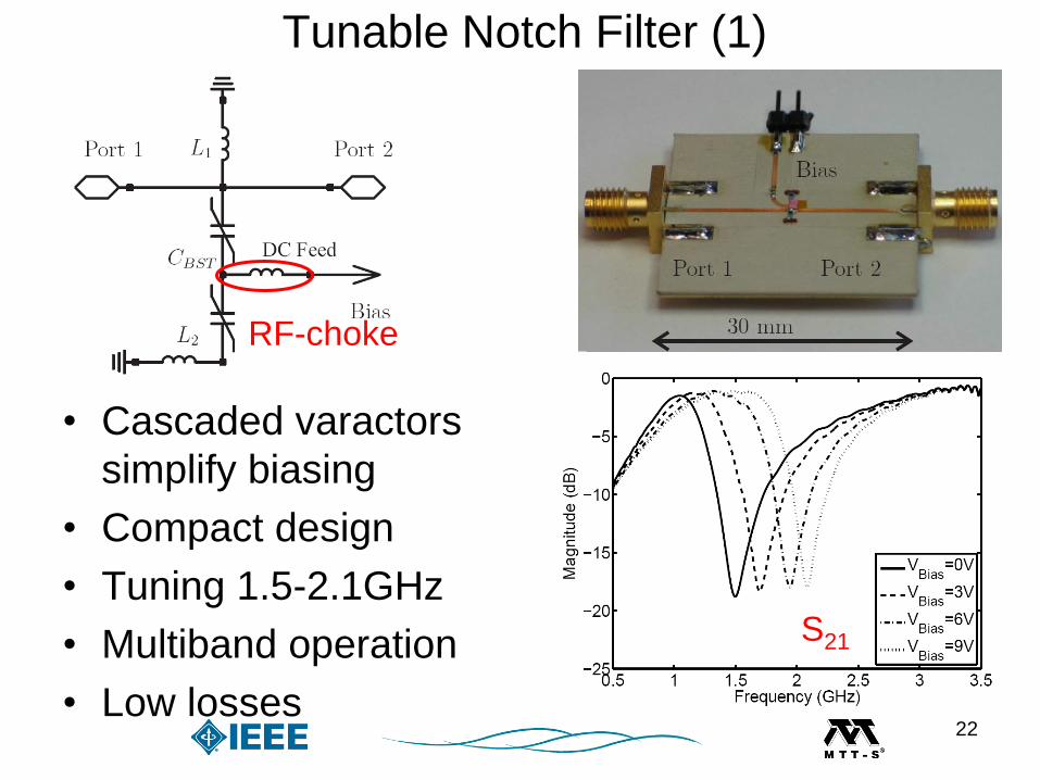
Tunable Notch Filter (1)
• Cascaded varactors
simplify biasing
• Compact design
• Tuning 1.5-2.1GHz
• Multiband operation
• Low losses
RF-choke
S21
22
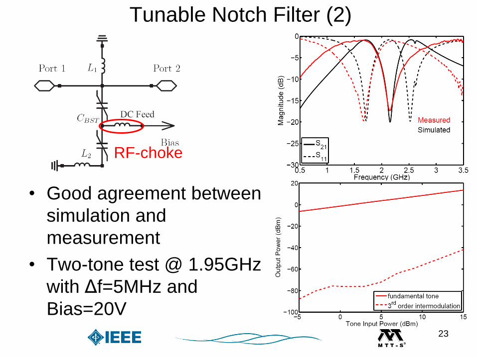
RF-choke
• Good agreement between
simulation and
measurement
• Two-tone test @ 1.95GHz
with Δf=5MHz and
Bias=20V
Tunable Notch Filter (2)
23
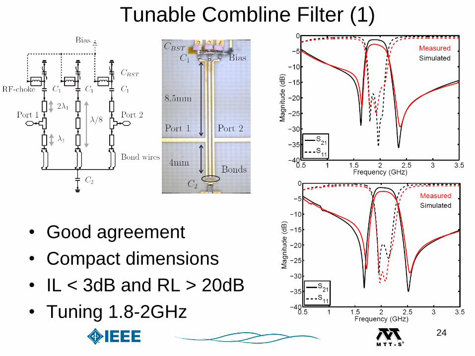
Tunable Combline Filter (1)
• Good agreement
• Compact dimensions
• IL < 3dB and RL > 20dB
• Tuning 1.8-2GHz24

• Two-tone test @1.95GHz
with Δf=5MHz and
Bias=5V
• Output 3rd order intercept
point OIP3=36.5dBm
Tunable Combline Filter (2)
25

Tunable Wilkinson Divider (1)
26

• IL < 1.2dB, Isolation > 25dB
• Size reduction 50%
• Lowpass filtering S21,S31
• Attenuation > 20dB at 2f0
• Tuning range 1.7-2.1GHz
Tunable Wilkinson Divider (2)
27
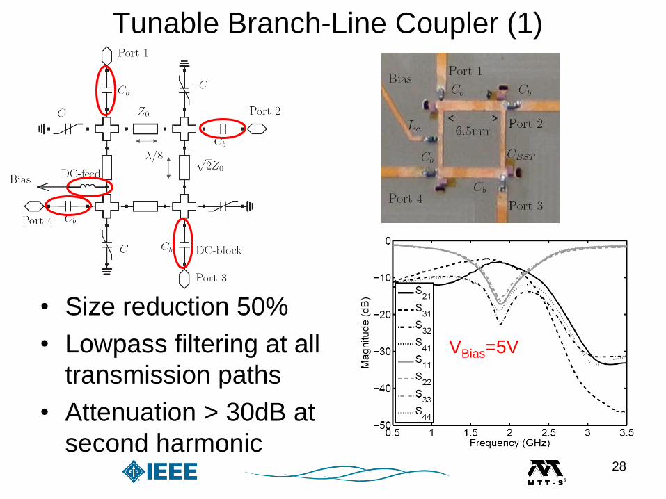
Tunable Branch-Line Coupler (1)
• Size reduction 50%
• Lowpass filtering at all
transmission paths
• Attenuation > 30dB at
second harmonic
VBias=5V
28
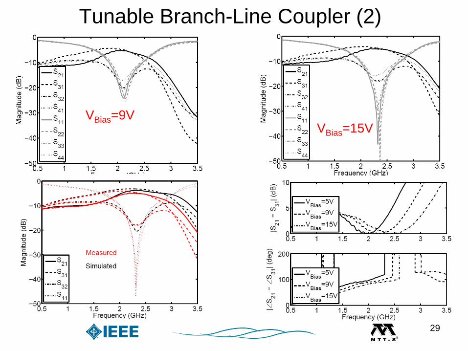
VBias=9VVBias=15V
Tunable Branch-Line Coupler (2)
29
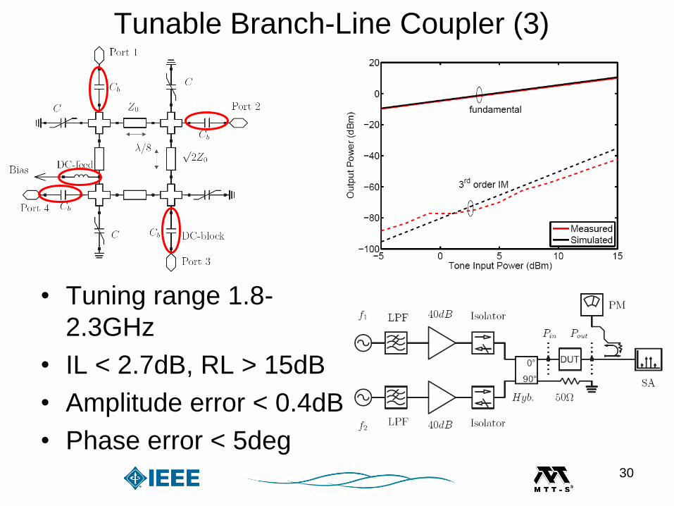
• Tuning range 1.8-
2.3GHz
• IL < 2.7dB, RL > 15dB
• Amplitude error < 0.4dB
• Phase error < 5deg
Tunable Branch-Line Coupler (3)
30
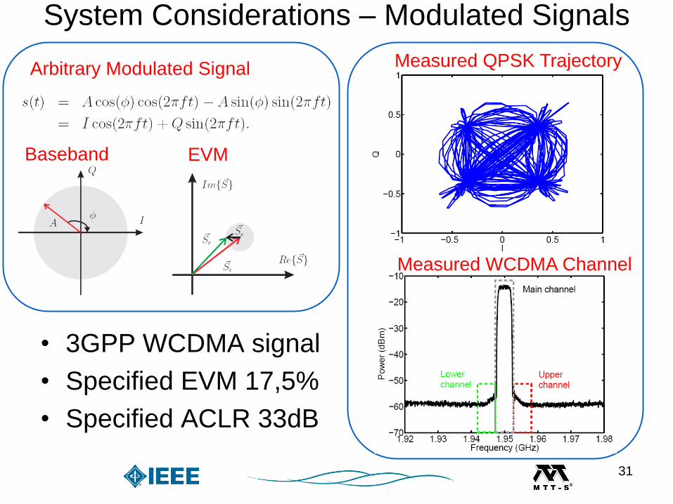
System Considerations – Modulated Signals
• 3GPP WCDMA signal
• Specified EVM 17,5%
• Specified ACLR 33dB
Arbitrary Modulated Signal
Baseband EVM
Measured QPSK Trajectory
Measured WCDMA Channel
31
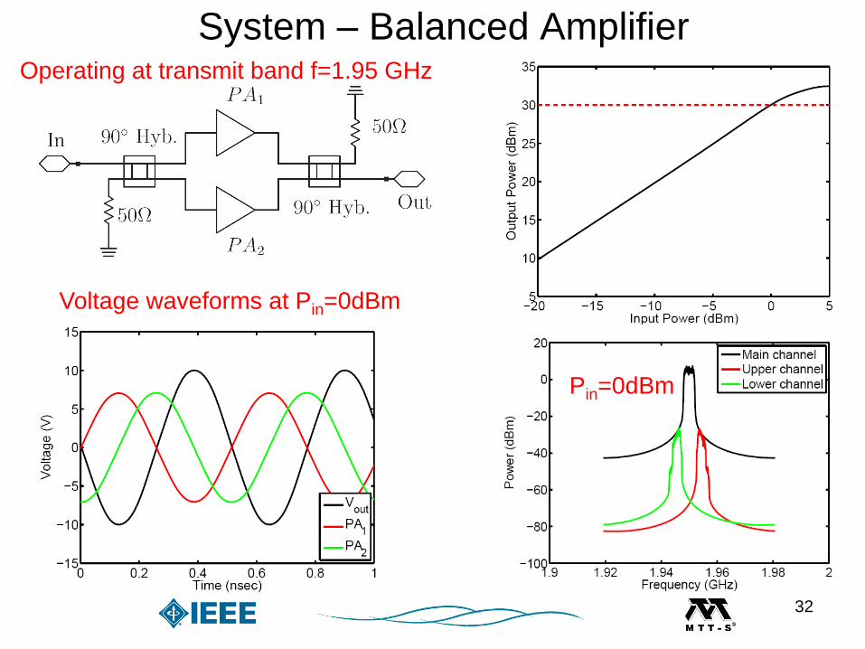
System – Balanced Amplifier
Voltage waveforms at Pin=0dBm
Pin=0dBm
Operating at transmit band f=1.95 GHz
32
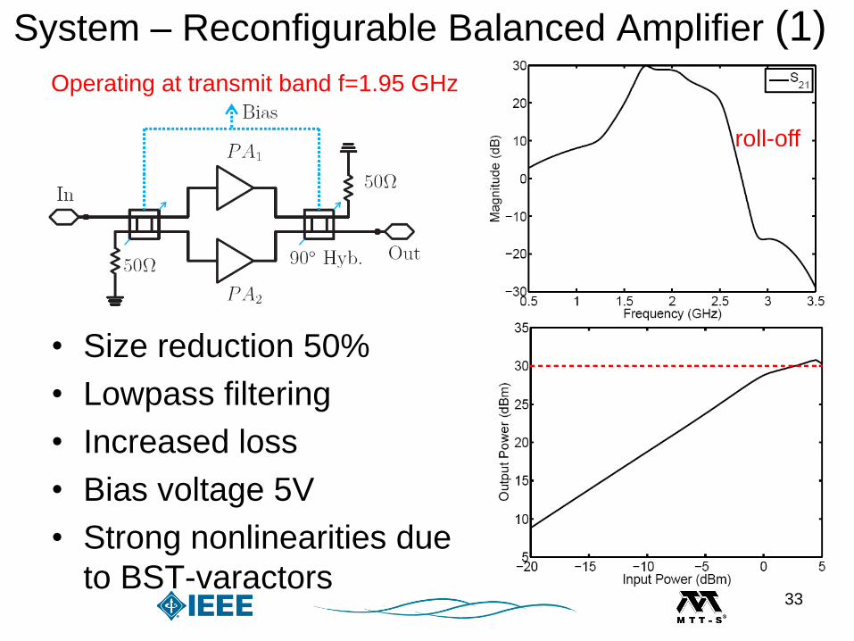
System – Reconfigurable Balanced Amplifier (1)
• Size reduction 50%
• Lowpass filtering
• Increased loss
• Bias voltage 5V
• Strong nonlinearities due
to BST-varactors
roll-off
Operating at transmit band f=1.95 GHz
33
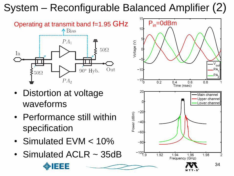
• Distortion at voltage
waveforms
• Performance still within
specification
• Simulated EVM < 10%
• Simulated ACLR ~ 35dB
Operating at transmit band f=1.95 GHz Pin=0dBm
System – Reconfigurable Balanced Amplifier (2)
34
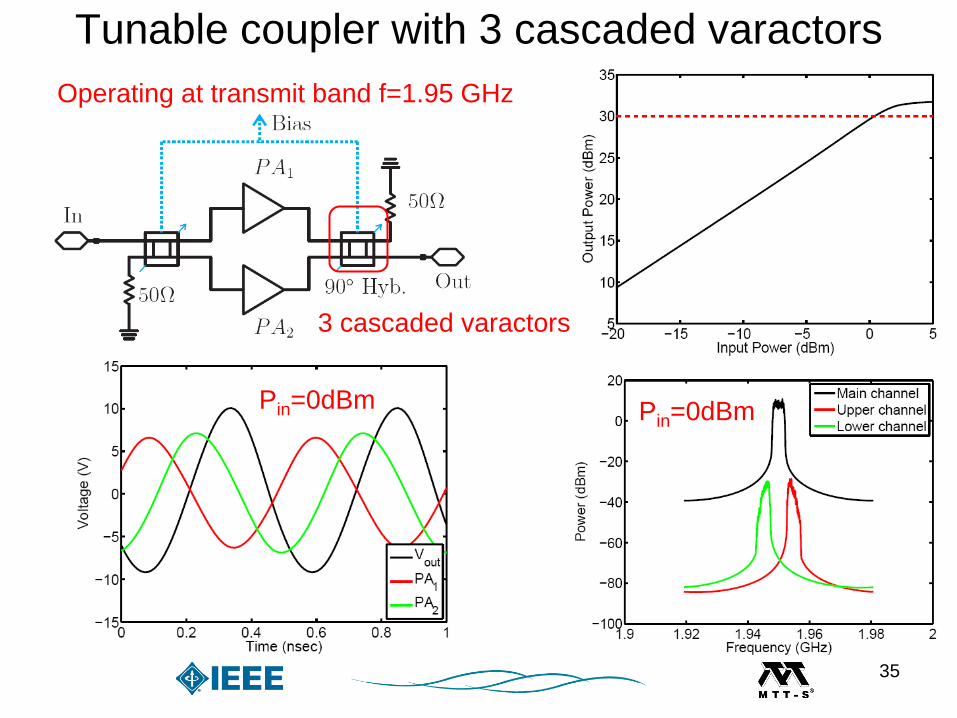
Tunable coupler with 3 cascaded varactors
Operating at transmit band f=1.95 GHz
Pin=0dBm Pin=0dBm
3 cascaded varactors
35
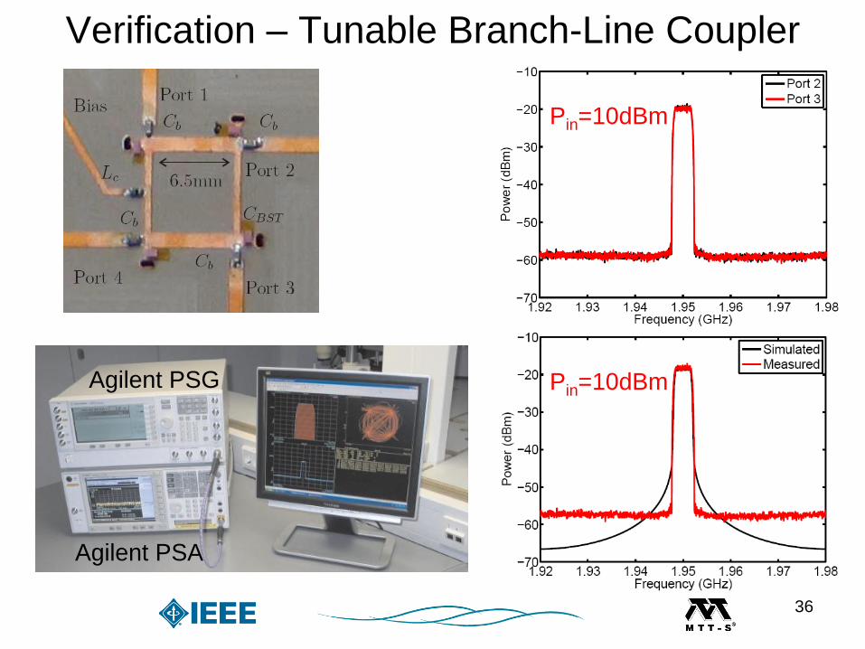
Verification – Tunable Branch-Line Coupler
Pin=10dBm
Agilent PSG
Agilent PSA
Pin=10dBm
36
Conclusion & OutlookConclusion
• Potential of ferroelectrics in tunable front-end
• Reliable modeling and characterization
• Candidates for tunable microwave circuits
– Frequency agile filters
– Reduced size tunable dividers and couplers
• Prototype implementation & results
• Overall good agreement to simulation
Outlook
• Integration of tunable subsystems into front-end
37