Embed Size (px)
Citation preview
ORIGINAL ARTICLE
Received August 18, 2018. In revised form December 08, 2018. Accepted December 08, 2018. Available online December 10, 2018. http://dx.doi.org/10.1590/1679-78255242
Latin American Journal of Solids and Structures, 2019, 16(2), e157 1/26
Free and forced vibration analysis of multiple cracked FGM multi span continuous beams using dynamic stiffness method
Tran Van Liena*
Ngo Trong Đucb
Nguyen Tien Khiemc
a National University of Civil Engineering - NUCE, Hanoi, Hanoi, Vietnam. E-mail: [email protected] b Design Consultant and Investment of Construction – DCIC, Hanoi, Hanoi, Vietnam. E-mail: [email protected]. c Institute of Mechanics, Vietnam Academy of Science and Technology - IMech, Hanoi, Hanoi, Vietnam. E-mail: [email protected].
*Corresponding author
http://dx.doi.org/10.1590/1679-78255242
Abstract In the present paper, the free and forced vibration of multiple cracked multi span continuous beams made of functionally graded material (FGM) is investigated by the dynamic stiffness method. First, there are constructed dynamic stiffness matrix and nodal load vector of multiple cracked FGM beam element using Timoshenko beam theory and massless double spring model of crack. Then, effect of cracks parameters on free and forced vibration of the FGM continuous beams is examined. The theoretical developments are validated by numerical examples. The obtained results provide an efficient method to analyze free and forced vibration of multiple cracked FGM framed structures and assessment of the behavior of damaged structures.
Keywords FGM; Multiple cracks; Timoshenko beam; Dynamic stiffness method; Vibration analysis..
1. Introduction
Functionally graded materials (FGMs) have proved to be more benefit in comparison with the laminate composites and found widespread application in the high-tech industries such as aerospace, automobile, electronics, optics, chemistry, biomedical engineering etc,... For vibration analysis of FGM structures, a number of methods have been proposed such as analytical (Nguyen, Vo, Nguyen, & Lee, 2016; Sina, Navazi, & Haddadpour, 2009), Rayleigh-Ritz method (Pradhan & Chakraverty, 2013), Galerkin (Sheng & Wang, 2018), combined Fourier series – Galerkin method (Zhu & Sankar, 2004), differential quadrature method (DQM) (Sundaramoorthy Rajasekaran, 2013a; Sınır, Çevik, & Sınır, 2018; Tang, Lv, & Yang, 2019), perturbation method (Sınır et al., 2018), asymptotic development method (Cao, Gao, Yao, & Zhang, 2018), discrete singular convolution and Taylor series expansion method (Wang & Yuan, 2017). While the aforementioned methods are limited to apply for analysis of simple FGM beam structures, the Finite Element Method (FEM) developed in (Alshorbagy, Eltaher, & Mahmoud, 2011; Eltaher, Abdelrahman, Al-Nabawy, Khater, & Mansour, 2014; Mashat, Carrera, Zenkour, Al Khateeb, & Filippi, 2014; Naccache & El Fatmi, 2018) could be used for more complex structures such as that are composed from different beam elements. However, because the FEM is developed on the base of the static shape functions, it requires a large amount of elements to study the high frequency components of vibration. This limitation of FEM could be overcome by using the Dynamic Stiffness Method (DSM) that was developed in (J. Banerjee, 2003; Deng & Cheng, 2016; S Rajasekaran, 2013b; Su & Banerjee, 2015; Su, Banerjee, & Cheung, 2013; Van Lien, Khiem, & Duc, 2016) with the frequency-dependent shape functions. The most important
Free and forced vibration analysis of multiple cracked FGM multi span continuous beams using dynamic stiffness method
Tran Van Lien et al.
Latin American Journal of Solids and Structures, 2019, 16(2), e157 2/26
advantage of the DSM is that allows investigating vibration of arbitrary high frequency with the minimum amount of elements.
Recently, vibrations of FGM beams with cracks have attracted attention of researchers because of the serious hazard that could be induced by the crack presence. The basic concepts of fracture mechanics for FGM structures have been given in (Erdogan & Wu, 1997; Jin & Batra, 1996) that are essentials to develop the models of crack in FGM structures. Namely, the continuous stiffness model (Christides & Barr, 1984; E. C. Yang, Zhao, & Li, 2015) proposes to treat a cracked FGM beam as the beam with continuously varying bending stiffness along its span. Therefore, the governing equation of vibration of the cracked FGM beam are similar to those of nonuniform beam that increases the difficulty to study beams made of FGM. An alternative model of crack that shows to be more appropriate for vibration analysis of cracked FGM beams was proposed by the use of rotational spring of stifness calculated in accordance with the concepts of fracture mechanics of FGM. Usefulness of the spring model of crack was validated in (A. Banerjee, Panigrahi, & Pohit, 2016) by using the 3D finite element formulation for an FGM beam with a crack. Using this model Yang et al. (J. Yang & Chen, 2008; J. Yang, Chen, Xiang, & Jia, 2008) have calculated natural frequencies, mode shapes and also response of cracked FGM Euler-Bernoulli beams to axial and moving loads. The influence of open edge cracks, material properties, beam slenderness ratio and end supports on free vibration of FGM Timoshenko beam was studied by Ke et al. (Ke, Yang, Kitipornchai, & Xiang, 2009). The dynamic deflections of cracked FGM beam on an elastic foundation under a transverse moving load were studied by Yan et al. (Yan, Kitipornchai, Yang, & He, 2011). The authors showed that the elastic foundation makes dynamic deflections of FGM beam more sensitive to cracks. The effects of the geometric and elastic characteristics on the natural frequencies and mode shapes of a cracked FGM beam rested on Winkler-Pasternak foundation were investigated by Matbuly et al. (Matbuly, Ragb, & Nassar, 2009) using differential quadrature method. The wave propagation in a cracked FGM cantilever beam under an impact force was considered by Akbas (Akbaş, 2016). The frequency equation in the form of third-order determinant that significantly simplifies calculating natural frequencies for FGM Euler-Bernoulli beam containing an arbitrary number of open edge cracks was established by Aydin (Aydin, 2013). The natural frequencies and mode shapes of multiple cracked FGM Timoshenko beam were investigated in (Lien, Duc, & Khiem, 2017a), (Lien, Đuc, & Khiem, 2017b) using the rotational spring model of cracks and actual position of neutral plane (Eltaher, Alshorbagy, & Mahmoud, 2013). The obtained results show that, natural frequencies calculated with respect to neutral axis are over estimated than those calculated at the centroidal axis. Wei et al (Wei, Liu, & Xiang, 2012) used spring model of crack to establish equations of motion of cracked FGM beam with rotary inertia and shear deformation included. Because of ignoring axial inertia, the bending vibration is uncoupled with axial one, so the model of cracks based only on rotational spring is inadequate for study of vibration in FGM beam where bending and longitudinal vibrations are usually coupled. To solve this problem, the two springs model of cracks were first instroduced by Sherafatnia et al. (Sherafatnia, Farrahi, & Faghidian, 2013), the cracks were modelled by two equivalent springs, one translational spring and one rotational spring with different stiffnesses evaluated based on the relations of the fracture mechanics. Using this model of cracks, the authors analyzed the natural frequencies and mode shapes of cracked FGM beam by different beam theories. Furthermore, Khiem et al. (N. Khiem & Huyen, 2017; N. T. Khiem, Huyen, & Long, 2017) also proposed two springs model of cracks which its stiffness calculated from crack depth. Unlikely to the previous studies, new formulas for determining crack magnitude of both the translational and rotational springs are proposed for arbitrary composition of FGM. These formulas allow one to use those developed in (Chondros, Dimarogonas, & Yao, 1998a, 1998b) for cracked homogeneous beam. Using that crack model, the authors investigated the sensitivity of natural frequencies to crack of the Timoshenko FGM beam and proposed an exact procedure for identifying location and depth of single crack from given natural frequencies. The FEM has been also developed for modal analysis and identification of FGM Euler-Bernoulli beam with an open crack (Akbaş, 2013). The p-version FEM model was engaged by Yu and Chu (Yu & Chu, 2009) to study change in frequencies and mode shapes of FGM beams due to crack location and size.
Although there is a widespread literature devoted to study vibration of FGM intact and cracked beam, most of them investigated simple beams except the Ref. (N. Khiem, Lien, & Ninh, 2018) where multistep FGM beam with cracks was studied by the transfer matrix method. In this paper, the DSM is developed to study continuous FGM beam with arbitrary number of cracks based on the Timoshenko beam theory; spring model of cracks and power law distribution of FGM. The most important novelty of the present study is to use general solution for vibration shape of an FGM beam element with arbitrary number of cracks for constructing the dynamic stiffness matrix and load vector. This allows one to investigate crack continuous FGM beam with minimal number of elements equal to the number of spans in the beam. Moreover, the formulas proposed by Khiem et al. (N. Khiem & Huyen, 2017; N. T. Khiem et al., 2017) for calculating stiffness of springs representing cracks in dependence of varying material properties have been used with taking into account the actual position of neutral plane of FGM Timoshenko beam. The obtained results provide an
Free and forced vibration analysis of multiple cracked FGM multi span continuous beams using dynamic stiffness method
Tran Van Lien et al.
Latin American Journal of Solids and Structures, 2019, 16(2), e157 3/26
efficient method for free and forced vibration analysis, as well as health monitoring of framed FGM structures with cracks.
2. Dynamic stiffness matrix and the nodal load vector of a multiple cracked FGM Timoshenko beam element
2.1. Governing equations
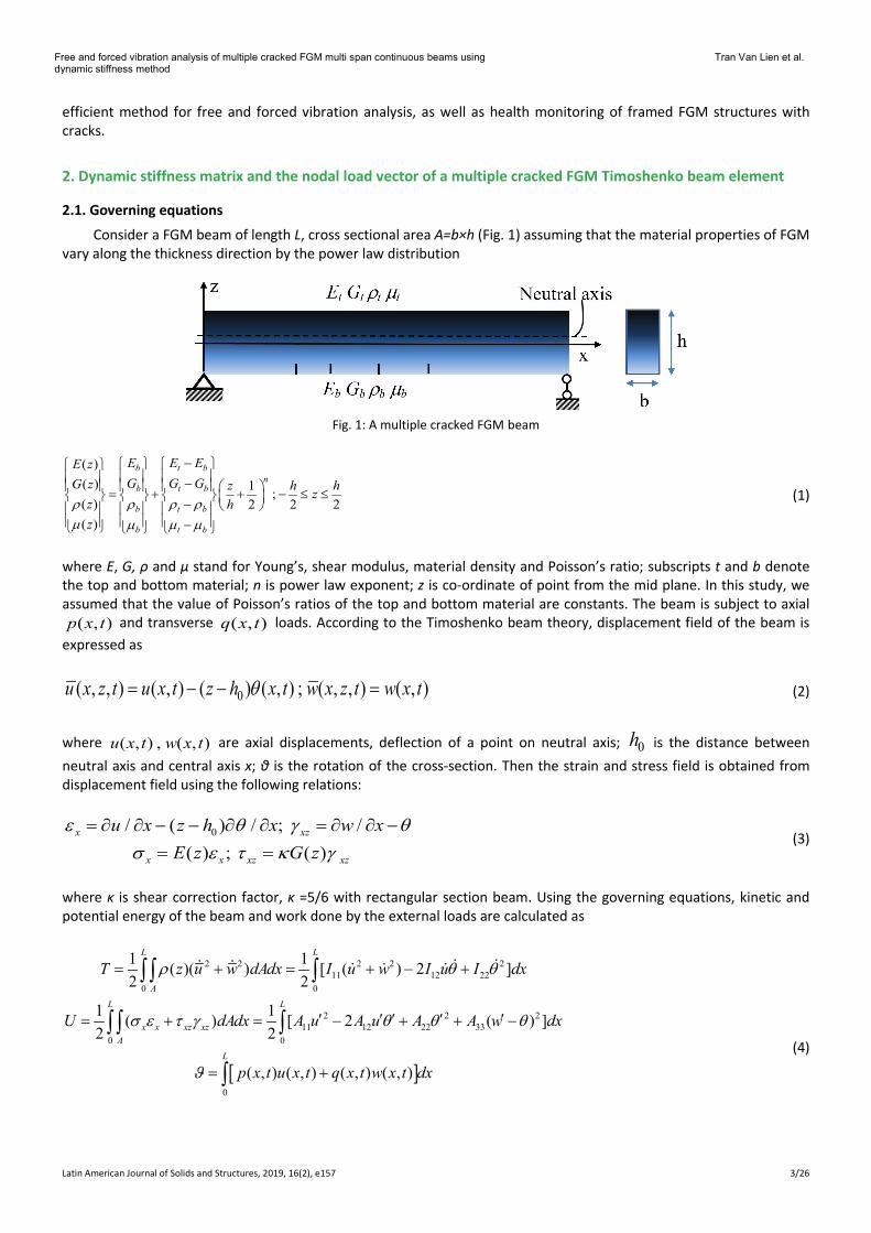
Consider a FGM beam of length L, cross sectional area A=b×h (Fig. 1) assuming that the material properties of FGM vary along the thickness direction by the power law distribution
Fig. 1: A multiple cracked FGM beam
( )( ) 1 ;( ) 2 2 2( )
b t bn
b t b
b t b
b t b
E E EE zG G GG z z h hz
z hz
ρ ρ ρ ρµ µ µ µ
− − = + + − ≤ ≤ −
−
(1)
where E, G, ρ and μ stand for Young’s, shear modulus, material density and Poisson’s ratio; subscripts t and b denote the top and bottom material; n is power law exponent; z is co-ordinate of point from the mid plane. In this study, we assumed that the value of Poisson’s ratios of the top and bottom material are constants. The beam is subject to axial
( , )p x t and transverse ( , )q x t loads. According to the Timoshenko beam theory, displacement field of the beam is expressed as
0( , , ) ( , ) ( ) ( , ) ; ( , , ) ( , )u x z t u x t z h x t w x z t w x tθ= − − = (2)
where ( , ) , ( , )u x t w x t are axial displacements, deflection of a point on neutral axis; 0h is the distance between neutral axis and central axis x; θ is the rotation of the cross-section. Then the strain and stress field is obtained from displacement field using the following relations:
0/ ( ) / ; /( ) ; ( )
x xz
x x xz xz
u x z h x w xE z G z
ε θ γ θσ ε τ κ γ
= ∂ ∂ − − ∂ ∂ = ∂ ∂ −
= = (3)
where κ is shear correction factor, κ =5/6 with rectangular section beam. Using the governing equations, kinetic and potential energy of the beam and work done by the external loads are calculated as
[ ]
2 2 2 2 211 12 22
0 0
2 2 211 12 22 33
0 0
0
1 1( )( ) [ ( ) 2 ]2 2
1 1( ) [ 2 ( ) ]2 2
( , ) ( , ) ( , ) ( , )
L L
AL L
x x xz xzA
L
T z u w dAdx I u w I u I dx
U dAdx A u A u A A w dx
p x t u x t q x t w x t dx
ρ θ θ
σ ε τ γ θ θ θ
ϑ
= + = + − +
′ ′ ′ ′ ′= + = − + + −
= +
∫ ∫ ∫
∫ ∫ ∫
∫
(4)
Free and forced vibration analysis of multiple cracked FGM multi span continuous beams using dynamic stiffness method
Tran Van Lien et al.
Latin American Journal of Solids and Structures, 2019, 16(2), e157 4/26
with the coefficients
( ) ( )( )( ) ( )( )
211 12 22 0 0 33
211 12 22 0 0
, , ( ) 1, , ; ( )
, , ( ) 1, ,
A A
A
A A A E z z h z h dA A G z dA
I I I z z h z h dA
κ
ρ
= − − =
= − −
∫ ∫
∫ (5)
Hence, using the Hamilton’s principle equations of motion in time domain are established as
11 11 12 12
12 12 22 22 33
11 33
( ) ( ) ( , )
( ) ( ) ( ) 0( ) ( , )
I u A u I A p x t
I u A u I A A wI w A w q x t
θ θ
θ θ θθ
′′ ′′− − − =
′′ ′′ ′− − − + − =′′ ′− − =
(6a)
with the physical boundary conditions
11 12 22 12 33; ; ( )x x x x xN A u A M A A u Q A wθ θ θ′ ′ ′ ′ ′= − = − = − (6b)
Using the Fourier transformation
{ } { } { } { }, , ( , ), ( , ), ( , ) ; ( , ), ( , ) ( , ), ( , )i t i tU W u x t x t w x t e dt P x Q x p x t q x t e dtω ωθ ω ω∞ ∞
− −
−∞ −∞
Θ = =∫ ∫ (7)
the equations of motion in the frequency domain can be obtained in the form
[ ]{ } [ ]{ } [ ]{ } { }′′ ′+ + = −A z Π z C z q (8a)
where the following notations for matrices, vectors have been introduced
2 211 1211 12
2 212 22 33 12 22 33
233 33 11
00 0 0 00 ; 0 0 ; 0 ;
0 0 0 0 0 0
I IA AA A A I I A
A A I
ω ω
ω ω
ω
−− = − = = − − −
A Π C (8b)
{ } { }{ , , } ; { ,0, }T TU W P Q= Θ =z q
In case of free vibration equation (8) is reduced to
[ ]{ } [ ]{ } [ ]{ } { }0′′ ′+ + =A z Π z C z (9)
2.2. General solution of cracked FGM beam element
Seeking solutions of equation (9) in the form xeλdz =0 , one obtains characteristic equation
2det[ ] 0.λ λ+ + =A Π C
Free and forced vibration analysis of multiple cracked FGM multi span continuous beams using dynamic stiffness method
Tran Van Lien et al.
Latin American Journal of Solids and Structures, 2019, 16(2), e157 5/26
This is in fact a cubic algebraic equation with respect to 2λη = with three roots η1,η2,η3 that allow for expressing solutions of above equation as (see Appendix 1)
1,4 1 2,5 2 3,6 3; ; ; , 1, 2,3.j jk k k k jλ λ λ η= ± = ± = ± = = (10)
Hence, general solution of the homogeneous equation (9) can be represented as
{ }1 1
6 6
11 12 16 1 1 2 2 6 6
0 21 22 26 1 2 6
31 32 36 1 1 2 2 6 6
... ...
... ... .
... ...z
x x
x x
d d d e C C C ed d d C C Cd d d e C C C e
λ λ
λ λ
α α α
β β β
= ⋅ =
(11)
with 1 6,...,C C being constants and
23312
2 2 2 211 11 11 33
; ; 1, 2,...,6.( )
jj j
j j
AI jI A I A
λωα βω λ ω λ
= = =+ +
(12)
Based on (10) and (12) it is easy to verify that:
362514362514 ;;;;; ββββββαααααα −=−=−====
therefore, solution (11) can be rewritten in the form
{ } [ ]{ }0 ( , ) ( , ) ,x xω ω=z G C (13)
where vector { } TCC ),...,( 61=C and matrix [ ]( , )x ωG is
[ ]
3 31 2 1 2
3 31 2 1 2
3 31 2 1 2
1 2 3 1 2 3
1 2 3 1 2 3
G , ) .
k x k xk x k x k x k x
k x k xk x k x k x k x
k x k xk x k x k x k x
e e e e e e
(x e e e e e e
e e e e e e
α α α α α α
ω
β β β β β β
−− −
−− −
−− −
=
− − −
(14)
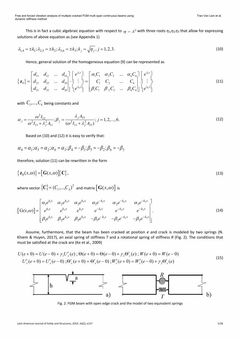
Assume, furthermore, that the beam has been cracked at position e and crack is modeled by two springs (N. Khiem & Huyen, 2017), an axial spring of stiffness T and a rotational spring of stiffness R (Fig. 2). The conditions that must be satisfied at the crack are (Ke et al., 2009)
)()0()0(;)0()0(;)0()0()0()0(;)()0()0(;)()0()0(
2
21
eeWeWeeeUeUeWeWeeeeUeUeU
xxxxxxx
xx
Θ′+−′=+′−Θ′=+Θ′−′=+′−=+Θ′+−Θ=+Θ′+−=+
γγγ
(15)
Fig. 2: FGM beam with open edge crack and the model of two equivalent springs
Free and forced vibration analysis of multiple cracked FGM multi span continuous beams using dynamic stiffness method
Tran Van Lien et al.
Latin American Journal of Solids and Structures, 2019, 16(2), e157 6/26
So called crack magnitudes 1 2,γ γ introduced in (15) can be calculated as functions of material parameters such as Young’s modulus, power exponent as
2 21 11 1 1 2 22 2 2/ 2 (1 ) ( ) ; / 6 (1 ) ( ) ; sA T h f s A R h f s a hγ π ν σ γ π ν σ= = − = = − = (16)
where (N. Khiem & Huyen, 2017)
( )( )( )
21 2
2 2 3 4 51
6 7 8
22
2 3 224( , ) ; ( , ) ; ;1 1 1 3(3 ) 2 1
( ) (0.6272 0.17248 5.92134 10.7054 31.5685 67.47
139.123 146.682 92.3552 );
( ) (0.6272 1.0453
E tE E EE E E
E E b
R n ER n R n R nR n R n RR n R n n n E
f s s s s s s s
s s s
f s s
σ σ α α+ + + +
= = − + = + + + + + +
= − + − + − +
+ − +
= − 2 3 4 5
6 7 8
3 4.5948 9.9736 20.2948 33.0351
47.1063 40.7556 19.6 ).
s s s s s
s s s
+ − + − +
+ − +
(17)
It is obviously that the crack magnitudes (16) include the case of homogeneous beam where
0t bE E E= = or / 1E t bR E E= =
Now, seeking a particular solution of equation (9) that satisfied conditions
{ } ( ) { } ( )1 1 2 1 2(0) ( ), ( ),0 ; (0) 0,0, ( )T Tx x xU e e eγ γ γ′ ′ ′ ′= Θ = Θz z
we obtain
{ }1 0 0( ) [ ( )][ ]{ ( )} [ ( )]{ ( )}cx x e x e′ ′= =z Φ Σ z G z (18)
where ( )TeWeeUe )()()()}({ 0000 ′Θ′′=′z and [Gc(x)] is 3×3- matrix
])][([)]([ ΣΦG xxc = (19)
with
[ ]1 1 2 2 3 3 11 12 13 1
1 2 3 21 22 23 2
1 1 2 2 3 3 31 32 33 2
cosh cosh cosh 0 0[ ( )] cosh cosh cosh ; 0 0
sinh sinh sinh 0 0
k x k x k xx k x k x k x
k x k x k x
α α α δ δ δ γδ δ δ γ
β β β δ δ δ γ
= ⋅ =
Φ Σ
and
( ) ( ) ( )( ) ( ) ( )( ) ( ) ( )
11 3 3 2 2 12 3 2 2 2 3 3 13 2 3
21 1 1 3 3 22 1 3 3 3 1 1 23 3 1
31 2 2 1 1 32 2 1 1 1 2 2 33 1 2
1 1 2 3 2 2 3 1 3 3 1 2
; ; ;
;
; ; ;( ) ( ) ( ).
k k k k
k k k k
k k k kk k k
δ β β δ α β α β δ α α
δ β β δ α β α β δ α α
δ β β δ α β α β δ α αβ α α β α α β α α
= − ∆ = − ∆ = − ∆
= − ∆; = − ∆; = − ∆
= − ∆ = − ∆ = − ∆
∆ = − + − + −
Free and forced vibration analysis of multiple cracked FGM multi span continuous beams using dynamic stiffness method
Tran Van Lien et al.
Latin American Journal of Solids and Structures, 2019, 16(2), e157 7/26
Introducing the matrices
[ ] [ ][ ] [ ] [ ]
[ ]
≤>′
=′
≤>
=0:0:)(
)(;0:0:)(
)(xxx
xxxx
x cc
0G
G0
GG (20)
General solution of equation (9) satisfying conditions (15) at crack position can be rewritten as
{ } { } { }1 0 0( ) ( ) G( ) . ( )x x x e e′ = + − z z z (21)
By the manner that is employed to obtain solution (21) one is able to conduct solution of equation (9) for beam
with single { }1( )xz and double { }2 ( )xz cracks as
{ } { } { } { } { } { } { }{ } { } { } { } { } { } { }( )
{ } { } { } { } { }
1 0 1 0 1 0 1 1 1 0 1
2 1 2 1 2 0 1 1 2 0 2 2 1 1
0 1 1 2 2 2 0 2
( ) ( ) ( ) . ( ) ( ) ( ) . ; ( )
( ) ( ) ( ) . ( ) ( ) ( ) . ( ) . ( ) ( ) .
( ) ( ) . ( ) . ; ( )
x x x e e x x e e
x x x e e x x e x e e e e
x x e x e e
′ ′ = + − = + − =
′ ′ ′ = + − = + − + − + −
′ = + − + − = +
z z G z z G μ μ z
z z G z z G μ G z G μ
z G μ G μ μ z { }2 1 1( ) .e e′ − G μ
So that solution of equation (9) for beam with n cracks can be expressed in the form
{ } { } { }01
( ) ( ) ( ) .n
c jj
x x x e=
= + − ∑ jz z G μ (22)
where so-called crack index vectors jμ are calculated by the recurrent formulas
{ } { } { }1
01
( ) ( ) . ; 1, 2,3,...,j
j j kk
e e e j n−
=
′ ′= + − = ∑j kμ z G μ (23)
Substituting governing solution expression (13) into (22) – (23), we obtain
{ } [ ] [ ][ ] { } ( )[ ]{ }CΨCχGGz j ωω ,~.)(),()(1
xexxxn
jjc =
−+= ∑
=
(24)
where
( )[ ] [ ] [ ][ ]jχGGΨ ~.)(),(,1∑=
−+=n
jjexxx ωω (25)
and
[ ] [ ] [ ][ ] njeeej
kkjj ,...,3,2,1;~.)()(~ 1
1=−′+′= ∑
−
=kj χGGχ (26)
On the other hand, a particular solution of equation (8) can be found in the form
{ } [ ]{ }0
( , ) ( , ) ( , )x
q x x dω τ ω τ ω τ= −∫z H q (27)
Free and forced vibration analysis of multiple cracked FGM multi span continuous beams using dynamic stiffness method
Tran Van Lien et al.
Latin American Journal of Solids and Structures, 2019, 16(2), e157 8/26
where [H(x,ω)] is matrix of transfer functions that satisfied equations
[ ][ ] [ ][ ] [ ][ ] [ ]0HCHΠHA =+′+′′ ... (28)
with boundary conditions
[ ] [ ] [ ] 1)0(;][)0( −=′= AH0H (29)
Hence, general solution of inhomogeneous equation (8) is composed of the general solution (24) and a particular solution (27)
{ } { } { } ( ) { } { }( , ) ( , ) ( , ) , ( , )c c q qx x x x xω ω ω ω ω= − = − z z z Ψ C z (30)
2.3. Dynamic stiffness matrix and nodal load vector
Let’s consider an 2D-dimensional FGM beam element as shown in Fig. 3. Nodal displacements and forces of the element are introduced as
{ } { } Te
Te QMNQMNWUWU },,,,,{;},,,,,{ˆ
222111222111 =ΘΘ= PU (31)
where
( ) ( ) ( )( ) ( ) ( )
1 1 1 2 1 3
2 1 2 2 2 3
1 11 1 12 2 1 22 2 12 1 1 33 3 20 0 0
2 11 1 12 2 2 22 2 12 1 2 33 3 2
(0, ) ; (0, ) ; (0, )( , ) ; ( , ) ; ( , )
; ;
; ;x x x x xx x x
x x x x xx L x L x L
U z z W zU z L z L W z L
N A z A z M A z A z Q A z z
N A z A z M A z A z Q A z z
ω ω ωω ω ω
= = =
= = =
= Θ = == Θ = =
= − ∂ − ∂ = − ∂ − ∂ = − ∂ −
= ∂ − ∂ = ∂ − ∂ = ∂ −
(32)
Fig. 3: Node co-ordinates, nodal loads of a beam element
Free and forced vibration analysis of multiple cracked FGM multi span continuous beams using dynamic stiffness method
Tran Van Lien et al.
Latin American Journal of Solids and Structures, 2019, 16(2), e157 9/26
Substituting expression (30) into (32), we get
{ } [ ][ ] { }
{ }{ } { }
( )( )
{ }( ){ }( ){ }
00(0, )ˆ ;( , ) ( )
F qF xxe e
q F x L F q x LL Lωω
==
= =
− − = − = ⋅ −
B zB Ψ0ΨU . C P C
Ψ z B Ψ B z (33)
with [BF] is the matrix operator
[ ]11 12
12 22
33 33
00
0B
x x
F x x
x
A AA A
A A
∂ − ∂ = − ∂ ∂ − ∂
(34)
Eliminating constant vector { }C in equation (33) leads to
{ } { } { }ˆ ˆ ˆ( ) ( ) .e e e eω ω = + P K U F (35)
where [ ]eK and { }eF are respectively dynamic stiffness matrix and nodal load vector of the multiple cracked FGM beam element
( )( )
[ ][ ]
10 (0, )ˆ[ ]
( , )F x
eF x L
Lωω
−=
=
− = ⋅
B Ψ ΨK
ΨB Ψ (36)
( )( )
[ ][ ]
{ }{ }
( ){ }( ){ }
100 (0, )ˆ{ } .
( , ) ( )
F qF xxe
qF x L F q x LL Lωω
−==
= =
− − = ⋅ −
B zB Ψ 0ΨF
Ψ zB Ψ B z (37)
For a given structure that consists of a number of FGM beam elements like above, by means of balancing all the
internal forces at every nodes of the structure, there will be obtained total dynamic stiffness matrix ˆ ( )ωK and nodal
load vector P . Letting U be the total DOF vector of the structure, equation of motion of which conducted by the dynamic stiffness method is
{ } { }ˆ ˆ ˆ( ) .ω = K U P (38)
Therefore, natural frequencies { } { }nωωωω ...21= can be found from of the equation
0)](ˆdet[ =ωK (39)
and mode shape related to the natural frequency ωj is
{ } ( ) { }0 ˆ ˆ( ) , jΨ Uj j jx C xϕ ω = (40)
Free and forced vibration analysis of multiple cracked FGM multi span continuous beams using dynamic stiffness method
Tran Van Lien et al.
Latin American Journal of Solids and Structures, 2019, 16(2), e157 10/26
where
[ ] [ ][ ]
1(0, )ˆ[ ( , )] ( , )( , )
ΨΨ Ψ
Ψx x
Lω
ω ωω
−
= ⋅
(41)
0jC is an arbitrary constant and { }jU is the normalized solution of (38) corresponding to ωj.
In case of forced vibration, so-called frequency response in an element, say e-th, of the structure would be calculated by
{ } { } { }{ } { }
0ˆ ˆˆˆ ( , ) ( , ) ( , ) ( , )( )
z Ψ U Ψ zze e q
qx x x x
Lω ω ω ω
= ⋅ + ⋅ −
(42)
3. Numerical results
3.1. Validation of the theoretical development
For validation of the proposed above theoretical development in this subsection, natural frequency ratios (cracked to intact), mode shapes of one-span FGM beam with different boundary conditions are computed and compared to those obtained in published studies.
Free and forced vibration analysis of multiple cracked FGM multi span continuous beams using dynamic stiffness method
Tran Van Lien et al.
Latin American Journal of Solids and Structures, 2019, 16(2), e157 11/26
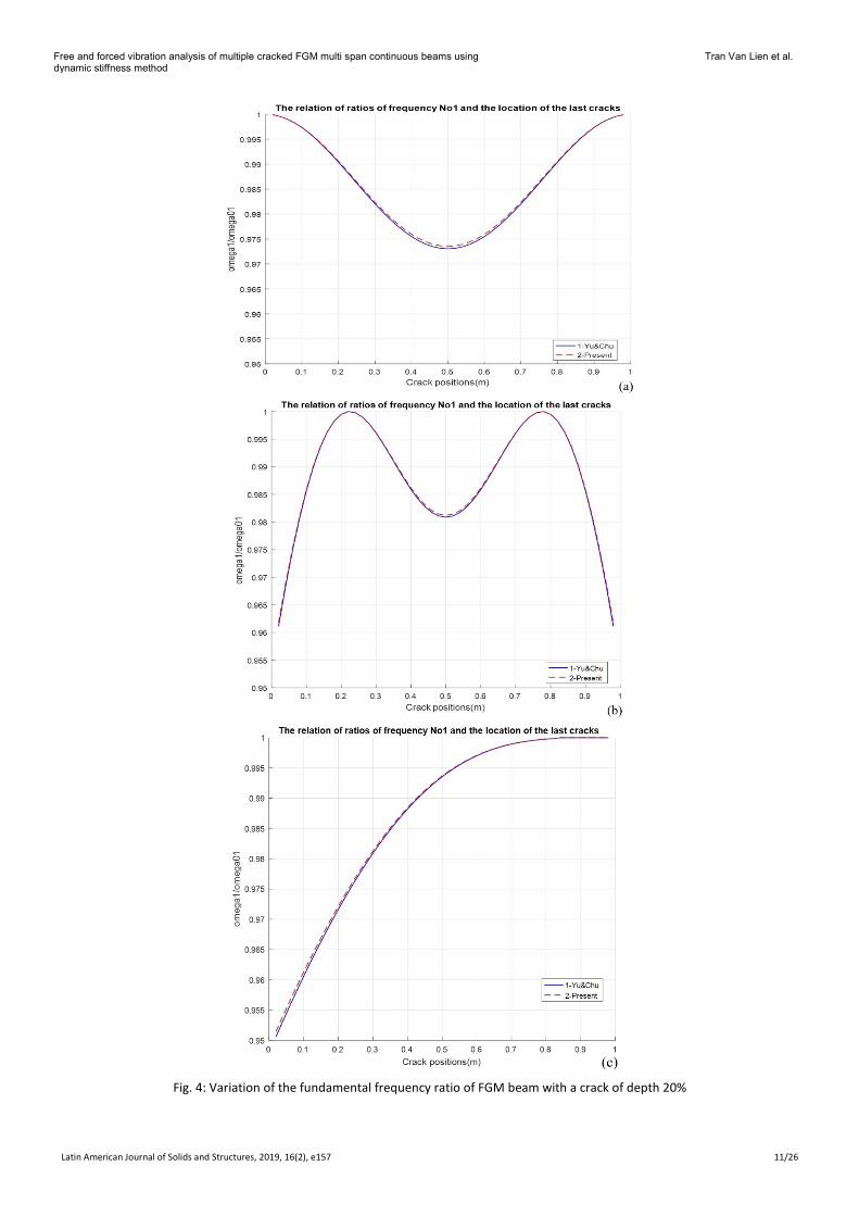
Fig. 4: Variation of the fundamental frequency ratio of FGM beam with a crack of depth 20%
Free and forced vibration analysis of multiple cracked FGM multi span continuous beams using dynamic stiffness method
Tran Van Lien et al.
Latin American Journal of Solids and Structures, 2019, 16(2), e157 12/26
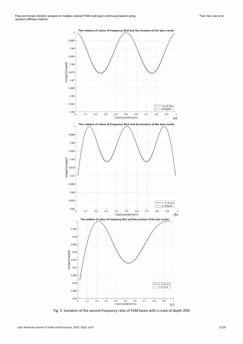
Fig. 5: Variation of the second frequency ratio of FGM beam with a crack of depth 20%
Free and forced vibration analysis of multiple cracked FGM multi span continuous beams using dynamic stiffness method
Tran Van Lien et al.
Latin American Journal of Solids and Structures, 2019, 16(2), e157 13/26
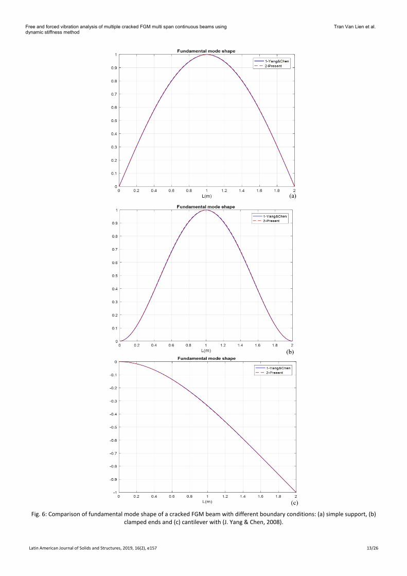
Fig. 6: Comparison of fundamental mode shape of a cracked FGM beam with different boundary conditions: (a) simple support, (b)
clamped ends and (c) cantilever with (J. Yang & Chen, 2008).
Free and forced vibration analysis of multiple cracked FGM multi span continuous beams using dynamic stiffness method
Tran Van Lien et al.
Latin American Journal of Solids and Structures, 2019, 16(2), e157 14/26
Figs. 4-5 show the variation of the first two frequency ratios (cracked/intact) of the FGM beam with an open edge crack of depth 20% along the crack position running from the left end to the right end of the beam. The results obtained in the present study are compared to those given by Yu & Chu (Yu & Chu, 2009) (continuous lines) using p-version of the FEM with different boundary conditions as: a) Simple support, b) Clamped ends and c) Cantilever. Graphs given in the Figures demonstrate good agreement of developed above DSM with the improved FEM. The fundamental mode shape of cracked FGM beam given in Fig. 6 in comparison with that obtained by Yang & Chen in (J. Yang & Chen, 2008) in different boundary conditions shows also excellent agreement of the DSM with the analytical method. This is a validation of not only the theory proposed above but also an advantage of the DSM developed for cracked FGM beam.
3.2. Free vibration of a multiple cracked FGM continuous beam
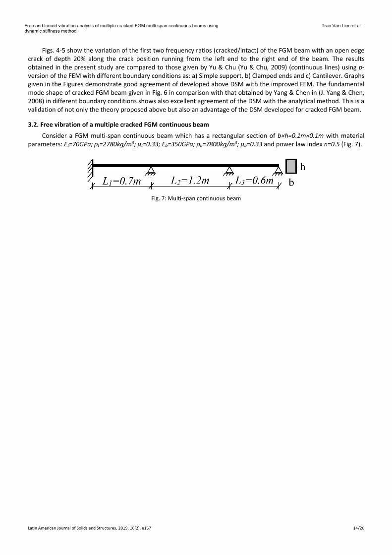
Consider a FGM multi-span continuous beam which has a rectangular section of b×h=0.1m×0.1m with material parameters: Et=70GPa; ρt=2780kg/m3; μt=0.33; Eb=350GPa; ρb=7800kg/m3; μb=0.33 and power law index n=0.5 (Fig. 7).
Fig. 7: Multi-span continuous beam
Free and forced vibration analysis of multiple cracked FGM multi span continuous beams using dynamic stiffness method
Tran Van Lien et al.
Latin American Journal of Solids and Structures, 2019, 16(2), e157 15/26
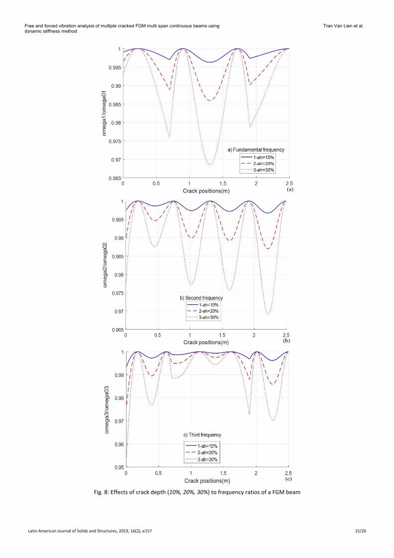
Fig. 8: Effects of crack depth (10%, 20%, 30%) to frequency ratios of a FGM beam
Free and forced vibration analysis of multiple cracked FGM multi span continuous beams using dynamic stiffness method
Tran Van Lien et al.
Latin American Journal of Solids and Structures, 2019, 16(2), e157 16/26
Fig. 8 shows the variation of the first three frequency ratios (cracked to intact) of three-span FGM beam with a crack of depth 10%, 20%, 30%. Observing graphs given in the Figures allows one to make the following remarks:
a) Crack on different beam spans effects differently on natural frequencies: The first frequency is most sensitive to the crack appeared at the second (middle) span, while the second frequency is most sensitive to crack at the right span (near pinned end). The third frequency gets largest change for crack located near both the clamped and pinned ends of the beam.
b) There exist positions on continuous FGM beam, crack appeared at which makes no effect on certain natural frequency. Such positions are called here critical points for a given frequency. The critical point positions from the left end of the beam are 0.22m, 0.895m, 1.72m for the first frequency; 0.185m, 0.74m, 1.31m, 1.915m for the second frequency and 0.17m, 0.62m, 1.134m, 1.61m, 2.011m for the third one. The critical points do not depend upon the number of cracks that occurred in the beam and thay are a useful indication for localizing cracks if unchange of a certain frequency is recognized.
Free and forced vibration analysis of multiple cracked FGM multi span continuous beams using dynamic stiffness method
Tran Van Lien et al.
Latin American Journal of Solids and Structures, 2019, 16(2), e157 17/26
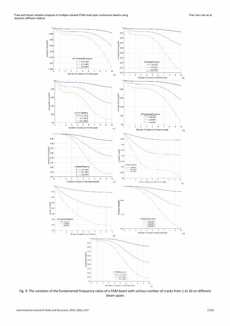
Fig. 9: The variation of the fundamental frequency ratios of a FGM beam with various number of cracks from 1 to 10 on different
beam spans
Free and forced vibration analysis of multiple cracked FGM multi span continuous beams using dynamic stiffness method
Tran Van Lien et al.
Latin American Journal of Solids and Structures, 2019, 16(2), e157 18/26
Fig. 9 shows the fundamental frequency ratios of a FGM beam varying with number of equidistant cracks from 1 to 10 in different cases of crack depths (10%, 20%, 30%). The graphs given in Figs. 9a-c show the frequency ratios for cracks on the first span, Figs. 9d-f and Figs. 9g-i for cracks on the second and third spans respectively. It is clear that increase of the number of cracks leads to more reduction of all the frequencies. It can be observed that variation of the frequencies is strongly dependent on which span the cracks are located.
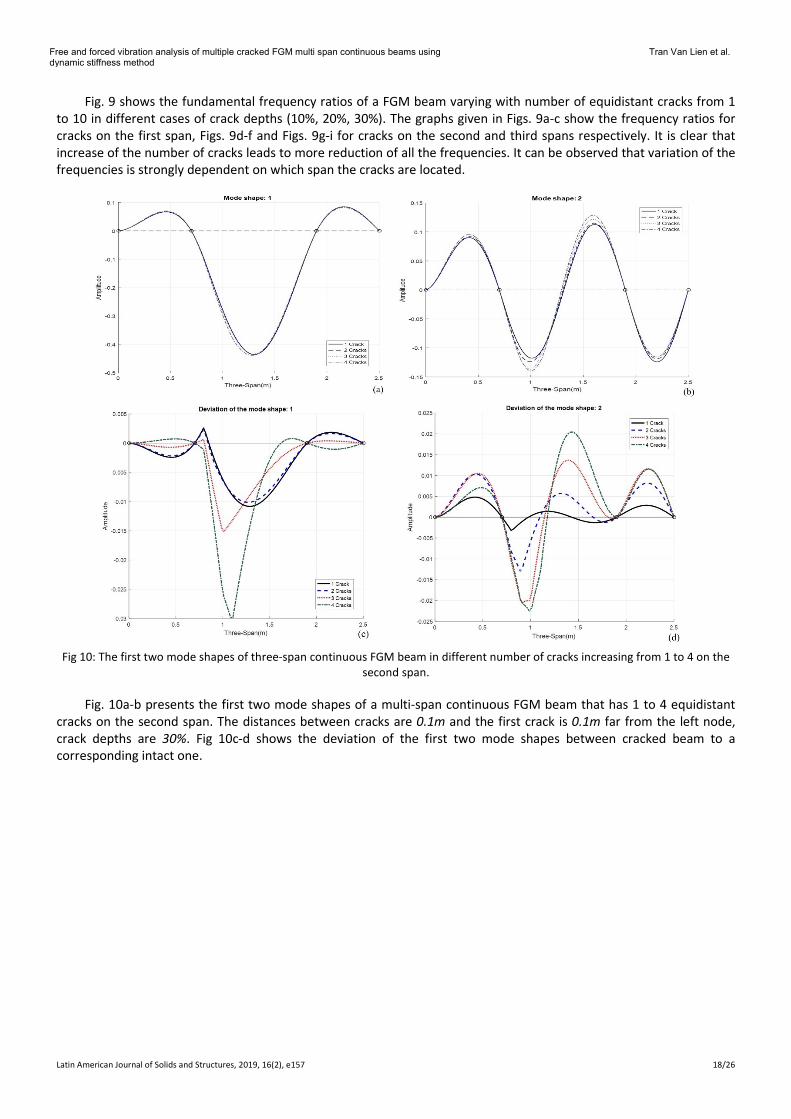
Fig 10: The first two mode shapes of three-span continuous FGM beam in different number of cracks increasing from 1 to 4 on the
second span.
Fig. 10a-b presents the first two mode shapes of a multi-span continuous FGM beam that has 1 to 4 equidistant cracks on the second span. The distances between cracks are 0.1m and the first crack is 0.1m far from the left node, crack depths are 30%. Fig 10c-d shows the deviation of the first two mode shapes between cracked beam to a corresponding intact one.
Free and forced vibration analysis of multiple cracked FGM multi span continuous beams using dynamic stiffness method
Tran Van Lien et al.
Latin American Journal of Solids and Structures, 2019, 16(2), e157 19/26
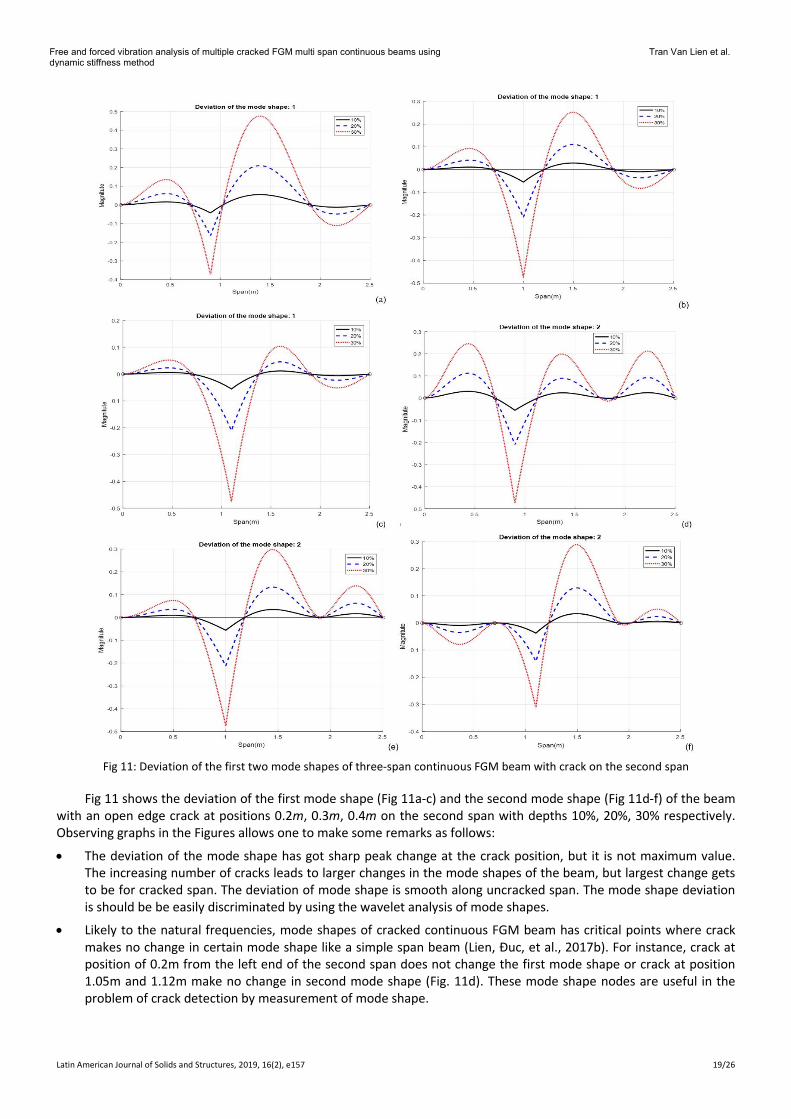
Fig 11: Deviation of the first two mode shapes of three-span continuous FGM beam with crack on the second span
Fig 11 shows the deviation of the first mode shape (Fig 11a-c) and the second mode shape (Fig 11d-f) of the beam with an open edge crack at positions 0.2m, 0.3m, 0.4m on the second span with depths 10%, 20%, 30% respectively. Observing graphs in the Figures allows one to make some remarks as follows:
• The deviation of the mode shape has got sharp peak change at the crack position, but it is not maximum value. The increasing number of cracks leads to larger changes in the mode shapes of the beam, but largest change gets to be for cracked span. The deviation of mode shape is smooth along uncracked span. The mode shape deviation is should be be easily discriminated by using the wavelet analysis of mode shapes.
• Likely to the natural frequencies, mode shapes of cracked continuous FGM beam has critical points where crack makes no change in certain mode shape like a simple span beam (Lien, Đuc, et al., 2017b). For instance, crack at position of 0.2m from the left end of the second span does not change the first mode shape or crack at position 1.05m and 1.12m make no change in second mode shape (Fig. 11d). These mode shape nodes are useful in the problem of crack detection by measurement of mode shape.
Free and forced vibration analysis of multiple cracked FGM multi span continuous beams using dynamic stiffness method
Tran Van Lien et al.
Latin American Journal of Solids and Structures, 2019, 16(2), e157 20/26
3.3. Forced vibration of a multiple cracked FGM continuous beam
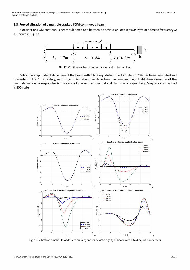
Consider an FGM continuous beam subjected to a harmonic distribution load q0=1000N/m and forced frequency ω as shown in Fig. 12.
Fig. 12: Continuous beam under harmonic distribution load
Vibration amplitude of deflection of the beam with 1 to 4 equidistant cracks of depth 20% has been computed and presented in Fig. 13. Graphs given in Figs. 13a-c show the deflection diagrams and Figs. 13d-f show deviation of the beam deflection corresponding to the cases of cracked first, second and third spans respectively. Frequency of the load is 100 rad/s.
Fig. 13: Vibration amplitude of deflection (a-c) and its deviation (d-f) of beam with 1 to 4 equidistant cracks
Free and forced vibration analysis of multiple cracked FGM multi span continuous beams using dynamic stiffness method
Tran Van Lien et al.
Latin American Journal of Solids and Structures, 2019, 16(2), e157 21/26
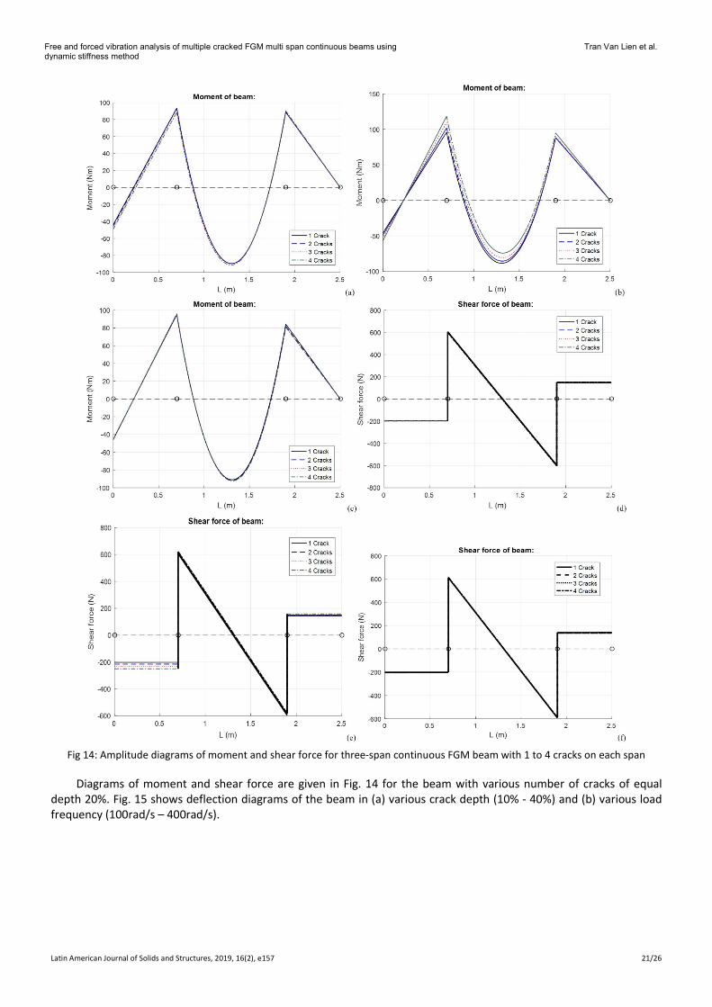
Fig 14: Amplitude diagrams of moment and shear force for three-span continuous FGM beam with 1 to 4 cracks on each span
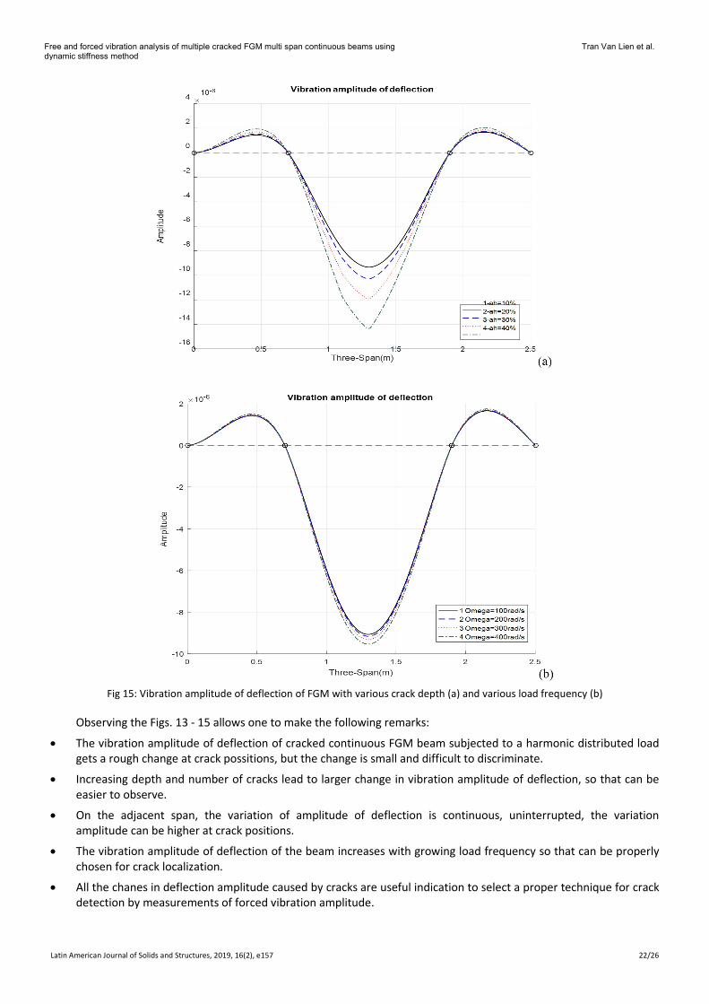
Diagrams of moment and shear force are given in Fig. 14 for the beam with various number of cracks of equal depth 20%. Fig. 15 shows deflection diagrams of the beam in (a) various crack depth (10% - 40%) and (b) various load frequency (100rad/s – 400rad/s).
Free and forced vibration analysis of multiple cracked FGM multi span continuous beams using dynamic stiffness method
Tran Van Lien et al.
Latin American Journal of Solids and Structures, 2019, 16(2), e157 22/26
Fig 15: Vibration amplitude of deflection of FGM with various crack depth (a) and various load frequency (b)
Observing the Figs. 13 - 15 allows one to make the following remarks:
• The vibration amplitude of deflection of cracked continuous FGM beam subjected to a harmonic distributed load gets a rough change at crack possitions, but the change is small and difficult to discriminate.
• Increasing depth and number of cracks lead to larger change in vibration amplitude of deflection, so that can be easier to observe.
• On the adjacent span, the variation of amplitude of deflection is continuous, uninterrupted, the variation amplitude can be higher at crack positions.
• The vibration amplitude of deflection of the beam increases with growing load frequency so that can be properly chosen for crack localization.
• All the chanes in deflection amplitude caused by cracks are useful indication to select a proper technique for crack detection by measurements of forced vibration amplitude.
Free and forced vibration analysis of multiple cracked FGM multi span continuous beams using dynamic stiffness method
Tran Van Lien et al.
Latin American Journal of Solids and Structures, 2019, 16(2), e157 23/26
4. Conclusions
In this paper, the dynamic stiffness method has been developed for vibration analysis of multiple cracked FGM continuous Timoshenko beams. Free and forced vibration of a three-span FGM continuous beam with multiple cracks have been examined to study effect of cracks and load on the beam natural frequencies, mode shapes and vibration amplitude. There are observed critical points for natural frequencies and mode shapes that are useful indicators in crack localization by measurements of the modal parameters. The crack-induced change in mode shapes and vibration amplitude of deflection demonstrates a possibility to propose an efficient procedure for crack detection by using wavelet analysis of the spatial vibration characteristics.
Acknowledgement
This research is funded by Vietnam National Foundation for Science and Technology Development (NAFOSTED) under grant number 107.02-2017.301.
References
Akbaş, Ş. D. (2013). Free vibration characteristics of edge cracked functionally graded beams by using finite element method. International Journal of Engineering Trends and Technology, 4(10), 4590-4597.
Akbaş, Ş. D. (2016). Wave propagation in edge cracked functionally graded beams under impact force. Journal of Vibration and Control, 22(10), 2443-2457.
Alshorbagy, A. E., Eltaher, M., & Mahmoud, F. (2011). Free vibration characteristics of a functionally graded beam by finite element method. Applied Mathematical Modelling, 35(1), 412-425.
Aydin, K. (2013). Free vibration of functionally graded beams with arbitrary number of surface cracks. European Journal of Mechanics-A/Solids, 42, 112-124.
Banerjee, A., Panigrahi, B., & Pohit, G. (2016). Crack modelling and detection in Timoshenko FGM beam under transverse vibration using frequency contour and response surface model with GA. Nondestructive Testing and Evaluation, 31(2), 142-164.
Banerjee, J. (2003). Free vibration of sandwich beams using the dynamic stiffness method. Computers & Structures, 81(18-19), 1915-1922.
Cao, D., Gao, Y., Yao, M., & Zhang, W. (2018). Free vibration of axially functionally graded beams using the asymptotic development method. Engineering Structures, 173, 442-448.
Chondros, T., Dimarogonas, A., & Yao, J. (1998a). A continuous cracked beam vibration theory. Journal of Sound and Vibration, 215(1), 17-34.
Chondros, T., Dimarogonas, A., & Yao, J. (1998b). Longitudinal vibration of a continuous cracked bar. Engineering fracture mechanics, 61(5-6), 593-606.
Christides, S., & Barr, A. (1984). One-dimensional theory of cracked Bernoulli-Euler beams. International Journal of Mechanical Sciences, 26(11-12), 639-648.
Deng, H., & Cheng, W. (2016). Dynamic characteristics analysis of bi-directional functionally graded Timoshenko beams. Composite Structures, 141, 253-263.
Eltaher, M., Abdelrahman, A., Al-Nabawy, A., Khater, M., & Mansour, A. (2014). Vibration of nonlinear graduation of nano-Timoshenko beam considering the neutral axis position. Applied mathematics and computation, 235, 512-529.
Eltaher, M., Alshorbagy, A., & Mahmoud, F. (2013). Determination of neutral axis position and its effect on natural frequencies of functionally graded macro/nanobeams. Composite Structures, 99, 193-201.
Erdogan, F., & Wu, B. (1997). The surface crack problem for a plate with functionally graded properties. Journal of applied Mechanics, 64(3), 449-456.
Jin, Z.-H., & Batra, R. (1996). Some basic fracture mechanics concepts in functionally graded materials. Journal of the Mechanics and Physics of Solids, 44(8), 1221-1235.
Free and forced vibration analysis of multiple cracked FGM multi span continuous beams using dynamic stiffness method
Tran Van Lien et al.
Latin American Journal of Solids and Structures, 2019, 16(2), e157 24/26
Ke, L.-L., Yang, J., Kitipornchai, S., & Xiang, Y. (2009). Flexural vibration and elastic buckling of a cracked Timoshenko beam made of functionally graded materials. Mechanics of Advanced Materials and Structures, 16(6), 488-502.
Khiem, N., & Huyen, N. (2017). A method for crack identification in functionally graded Timoshenko beam. Nondestructive Testing and Evaluation, 32(3), 319-341.
Khiem, N., Lien, T., & Ninh, V. (2018). Natural Frequencies of Multistep Functionally Graded Beam with Cracks. Iranian Journal of Science and Technology, Transactions of Mechanical Engineering, 1-36.
Khiem, N. T., Huyen, N. N., & Long, N. T. (2017). Vibration of cracked Timoshenko beam made of functionally graded material. In Shock & Vibration, Aircraft/Aerospace, Energy Harvesting, Acoustics & Optics, Volume 9 (pp. 133-143): Springer.
Lien, T. V., Duc, N. T., & Khiem, N. T. (2017a). Free Vibration Analysis of Multiple Cracked Functionally Graded Timoshenko Beams. Latin American Journal of Solids and Structures, 14(9), 1752-1766.
Lien, T. V., Đuc, N. T., & Khiem, N. T. (2017b). Mode Shape Analysis of Multiple Cracked Functionally Graded Timoshenko Beams. Latin American Journal of Solids and Structures, 14(7), 1327-1344.
Mashat, D. S., Carrera, E., Zenkour, A. M., Al Khateeb, S. A., & Filippi, M. (2014). Free vibration of FGM layered beams by various theories and finite elements. Composites Part B: Engineering, 59, 269-278.
Matbuly, M., Ragb, O., & Nassar, M. (2009). Natural frequencies of a functionally graded cracked beam using the differential quadrature method. Applied mathematics and computation, 215(6), 2307-2316.
Naccache, F., & El Fatmi, R. (2018). Numerical free vibration analysis of homogeneous or composite beam using a refined beam theory built on Saint Venant’s solution. Computers & Structures, 210, 102-121.
Nguyen, T.-K., Vo, T. P., Nguyen, B.-D., & Lee, J. (2016). An analytical solution for buckling and vibration analysis of functionally graded sandwich beams using a quasi-3D shear deformation theory. Composite Structures, 156, 238-252.
Pradhan, K., & Chakraverty, S. (2013). Free vibration of Euler and Timoshenko functionally graded beams by Rayleigh–Ritz method. Composites Part B: Engineering, 51, 175-184.
Rajasekaran, S. (2013a). Free vibration of centrifugally stiffened axially functionally graded tapered Timoshenko beams using differential transformation and quadrature methods. Applied Mathematical Modelling, 37(6), 4440-4463.
Rajasekaran, S. (2013b). Buckling and vibration of axially functionally graded nonuniform beams using differential transformation based dynamic stiffness approach. Meccanica, 48(5), 1053-1070.
Sheng, G., & Wang, X. (2018). Nonlinear vibration of FG beams subjected to parametric and external excitations. European Journal of Mechanics-A/Solids, 71, 224-234.
Sherafatnia, K., Farrahi, G., & Faghidian, S. A. (2013). Analytic approach to free vibration and buckling analysis of functionally graded beams with edge cracks using four engineering beam theories. International Journal of Engineering-Transactions C: Aspects, 27(6), 979-990.
Sina, S., Navazi, H., & Haddadpour, H. (2009). An analytical method for free vibration analysis of functionally graded beams. Materials & Design, 30(3), 741-747.
Sınır, S., Çevik, M., & Sınır, B. G. (2018). Nonlinear free and forced vibration analyses of axially functionally graded Euler-Bernoulli beams with non-uniform cross-section. Composites Part B: Engineering, 148, 123-131.
Su, H., & Banerjee, J. (2015). Development of dynamic stiffness method for free vibration of functionally graded Timoshenko beams. Computers & Structures, 147, 107-116.
Su, H., Banerjee, J., & Cheung, C. (2013). Dynamic stiffness formulation and free vibration analysis of functionally graded beams. Composite Structures, 106, 854-862.
Tang, Y., Lv, X., & Yang, T. (2019). Bi-directional functionally graded beams: asymmetric modes and nonlinear free vibration. Composites Part B: Engineering, 156, 319-331.
Van Lien, T., Khiem, N. T., & Duc, N. T. (2016). Free vibration analysis of functionally graded Timoshenko beam using dynamic stiffness method. Journal of Science and Technology in Civil Engineering (STCE)-NUCE, 10(5), 19-28.
Wang, X., & Yuan, Z. (2017). Discrete singular convolution and Taylor series expansion method for free vibration analysis of beams and rectangular plates with free boundaries. International Journal of Mechanical Sciences, 122, 184-191.
Free and forced vibration analysis of multiple cracked FGM multi span continuous beams using dynamic stiffness method
Tran Van Lien et al.
Latin American Journal of Solids and Structures, 2019, 16(2), e157 25/26
Wei, D., Liu, Y., & Xiang, Z. (2012). An analytical method for free vibration analysis of functionally graded beams with edge cracks. Journal of Sound and Vibration, 331(7), 1686-1700.
Yan, T., Kitipornchai, S., Yang, J., & He, X. Q. (2011). Dynamic behaviour of edge-cracked shear deformable functionally graded beams on an elastic foundation under a moving load. Composite Structures, 93(11), 2992-3001.
Yang, E. C., Zhao, X., & Li, Y. H. (2015). Free vibration analysis for cracked FGM beams by means of a continuous beam model. Shock and Vibration, 2015.
Yang, J., & Chen, Y. (2008). Free vibration and buckling analyses of functionally graded beams with edge cracks. Composite Structures, 83(1), 48-60.
Yang, J., Chen, Y., Xiang, Y., & Jia, X. (2008). Free and forced vibration of cracked inhomogeneous beams under an axial force and a moving load. Journal of Sound and Vibration, 312(1-2), 166-181.
Yu, Z., & Chu, F. (2009). Identification of crack in functionally graded material beams using the p-version of finite element method. Journal of Sound and Vibration, 325(1-2), 69-84.
Zhu, H., & Sankar, B. (2004). A combined Fourier series–Galerkin method for the analysis of functionally graded beams. Journal of applied Mechanics, 71(3), 421-424.
Free and forced vibration analysis of multiple cracked FGM multi span continuous beams using dynamic stiffness method
Tran Van Lien et al.
Latin American Journal of Solids and Structures, 2019, 16(2), e157 26/26
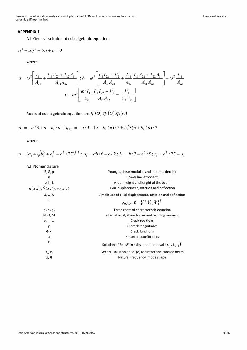
APPENDIX 1
A1. General solution of cub algebraic equation
023 =+++ cba ηηη
where
−
−=
−
++
−=
++=
2211
211
2211
2122211
33
112
4
22
112
2211
11222211
33
11
2211
21222114
2211
11222211
33
112 ;
AAI
AAIII
AIc
AI
AAAIAI
AI
AAIIIb
AAAIAI
AIa
ωω
ωωω
Roots of cub algebraic equation are )(),(),( 321 ωηωηωη
2/)/(32/)/(3/;/3/ 113,211 ubuiubuaubua +±−−−=−+−= ηη
where
13
12
113/132
1311 27/;9/3/;2/6/;)27/( aacabbcabaacbau −=−=−=−++=
A2. Nomenclature E, G, ρ Young’s, shear modulus and materila density
n Power law exponent b, h, L width, height and lenght of the beam
( , ) , ( , ) , ( , )u x t x t w x tθ Axial displacement, rotation and deflection
U, Θ,W Amplitude of axial displacement, rotation and deflection z
Vector TWU },,{ Θ=z
η1,η2,η3 Three roots of characteristic equation N, Q, M Internal axial, shear forces and bending moment e1,...,en Crack positions
γj jth crack magnitudes G(x) Crack functions
μj Recurrent coefficients zj Solution of Eq. (8) in subsequent interval ),( 1+jj ee
z0, zc General solution of Eq. (8) for intact and cracked beam ω, Ψ Natural frequency, mode shape