Embed Size (px)
Citation preview

FRAMLAST 2013-10-31
P. Andersson P. Hugoson S. Sökjer-Petersen
University of Žilina J. Jagelčák J. Ferleťák J. Vrábel Ľ. Rovňaník T. Skrúcaný 2013-10-31
Tel. +46 (0)42 33 31 00 Fax. +46 (0)42 33 31 02
P.O. Box 74 SE-263 21 Höganäs, SWEDEN
www.mariterm.se [email protected]
FRAMLAST
Development of intermodal cargo transport units
FRAMLAST 2013-10-31
ii
PREFACE The FRAMLAST project has been carried out within the virtual research and demonstration center – “Swedish Intermodal Research Centre” – Sir-C, as one of the final projects within this consortium. The project has been financed by the National Swedish Rail Administration and the Swedish Road Administration, present the Swedish Transport Administration. The project has been carried out in close co-operation with the Department of Road and Urban Transport of the University of Zilina. Comments and observations on the cargo transport units, CTUs, from other already completed projects within Sir-C have been considered and the project idea FRAMLAST emerged from these observations. The industry is also wondering about the future generally available CTU in the medium term (about 20 years); What is the performance of future CTU for combined transport? Will there be other types of units than today? What capacity, volume and dimensions will they have and which possibilities are there? According to agreement some time of the project has been devoted to the completed project CombiSec – “Proposal of unified cargo securing principles for road and combined transport trains”. This project identified cargo securing methods that are in accordance with valid road regulations and that could provide a sufficient and acceptable level of cargo securing during combined transports by rail. Tests, documentation and all the preparatory work to prove that cargo securing regulations for road transport also applies for combined transport by rail is already done in the CombiSec project. In the FRAMLAST project efforts are made to try to convince the International Union of Railways, UIC, to update the UIC Loading Guidelines and implement the conclusions of the CombiSec project. The work within FRAMLAST was divided into three parts; a continuation of the CombiSec project and trying to convince UIC to revise the rules for securing loads in combined units during transport by rail to be in accordance with the rules for road transport, a global part where the design of future CTUs for European transports in the coming 20 years are studied and a third part regarding details on CTUs to improve cargo securing and cargo care. A large number of Swedish companies and organizations have participated in the project work, see list of participating companies in section 1.4 below. All participants have been invited to the project meetings that have been held during the project period, and the attendance in the meetings has been large or even very large. Erik Andersson from IKEA and Mats Willén from the Swedish Transport Agency have alternated as chairman during the project meetings. All participants have been very active in the project work and eager to see a result of the work. We wish to thank all involved for valuable contribution and help during the project period. Höganäs, 2013-10-31
Project Team: MariTerm AB University of Zilina Peter Andersson Juraj Jagelčák Jozef Ferleťák Petra Hugoson Ján Vrábel Ľubor Rovňaník Sven Sökjer-Petersen Tomáš Skrúcaný
FRAMLAST 2013-10-31
iii
SUMMARY The FRAMLAST project has been carried out within the virtual research and demonstration center – “Swedish Intermodal Research Centre” – Sir-C. Comments and observations from other projects within this center on existing Cargo Transport Units, CTUs, and questions about the future CTU in the medium term (about 20 years) emerged the FRAMLAST project idea. The industry is also wondering about the future generally available CTU; What is the performance of the future cargo transport unit for combined transport? Will there be other types of units than today? What capacity, volume and dimensions will it have and which possibilities are there? FRAMLAST is a study of performance of future CTUs to be used in intermodal transports within Europe, focusing on the cargo and the cargo care; both overall and in part on the level of details, taking into account different types of cargo, transport modes, ways of handling and administration etc. Also requirements from sea transport are included. Furthermore, actual CTUs as semi-trailers, swap bodies and freight containers is investigated to get their strong and weak points and if some changes in the design are required to be developed to facilitate intermodal transports. The work within FRAMLAST was divided into three parts; a continuation of the CombiSec project and trying to convince UIC to revise the rules for securing loads in combined units during transport by rail to be in accordance with the rules for road transport; a global part where the design of future CTUs for European transports are studied and the third part was a study of details on CTUs to improve cargo securing and cargo care. There is no European directive or regulation on required cargo securing equipment on European vehicles. However, there are a number of non-mandatory standards available within Europe. The expected result of the project is a proposal of changes of these standards on actual CTUs which better fulfil requirements from different kind of cargo and modes of transport in an intermodal transport chain, especially concerning transport quality and handling of CTUs between different modes of transport. This can make it easier for the cargo owners to choose intermodal transport solutions instead of pure road transports. The public interest is to decrease the pure road transports and instead increase combinations of road, rail and sea transports. A compilation of existing knowledge and experiences regarding intermodal CTUs from earlier research projects is made within the project. The PROTECTED and INTERSYS projects was dealing with security of CTUs. Demands of possibilities of protection against smuggling, theft and sabotage are steadily increasing and in the future there might be requests of identification tools and technologies for implementation in intermodal freight transport systems. The project RASLA focused on the problems to secure cargo in a rational way with existing equipment and showed examples of equipment giving lorry drivers and other personnel involved possibility to make the work with the cargo securing more rational. For example the lashing bar, in the project named side beam for optional fastening of lashings inside as well as outside the sideboards, was introduced in this project and a prototype was produced and installed on the cargo securing vehicle, owned by TYA (Transportfackens Yrkes- och Arbetsmiljönämnd). In the EU-funded project TELLIBOX a couple of MegaSwapBoxes, Tellibox, was produced and tested on a limited market. The Tellibox can
FRAMLAST 2013-10-31
iv
be used for road, rail and sea transport and have advantages as stackability, inside height of 3 m, 45’ length, three openable sides and is pilfer and theft-proof. The disadvantage is that the Tellibox is suitable on adapted chassis during road transport and for use on low-loader railway wagons only. No commercial production of the unit has taken place. During the project study visits at the Port of Åhus, Port of Gothenburg, Cronos Containers, Schmitz Cargobull, GDL, Börje Jönsson Åkeri and Ability Landin AB with Transatlantic connected by phone, have been carried out. A meeting has been arranged in Helsingborg with representatives from Krone and some important information was found out during a cargo securing training focusing on vehicle superstructures. Visits at fair trades in Munich and Hannover and at a seminar “High Capacity Transport, infrastructure and road safety” have also been performed. Based on these study visits and meetings mapping of the current performance and typical parameters for trailers, swap bodies, containers and flat racks of today was carried out. Also high capacity transports (HCT) is discussed in the project. A number of field studies and tests have been carried out within the project. A field study of containers was carried out in different container terminals in Slovakia, Czech Republic and Sweden. A pre-study of testing the strength in the corrugation and in the lashing points in ISO containers was carried out in Gothenburg with a container from Cronos. Additional tests were performed within the research activities of the Department of Road and Urban Transport, University of Zilina, Slovakia, with containers from Hapag-Lloyd. General purpose maritime containers present the majority of containers used for international sea transports. Several terminal operators have made it possible to make a field study of 20’ and 40’ general purpose containers by allowing inspections of empty containers in their empty storage yards. From the point of cargo securing maritime container is a structure with strong walls and other cargo securing systems, mainly lashing rings and lashing bars. The field study contains an inspection of almost 400 containers and an analysis of the size and type of container, the strength, number, type and position of securing points and the strength of the side and end walls of the containers. In the container tests the strength of securing points and in the corrugation was performed. The results of the tests of the strength of the securing points show that the quality of the welding strongly influences the strength of the lashing points and lashing bars. The lashing rings at the floor level in the tested containers broke in some of the tests, but the lashing rings at the roof level was deformed only once when the vertical lashing angle was zero. No welding broke at the roof level. All lashing points and lashing bars were capable of withstanding at least 1000 daN in the tested directions. The largest strength of lashing rings and bars is when the lashing leads close to the container walls. It can be concluded from the tests that a MSL of 2000 daN for lashing rings (Ø12) is reasonable for vertical lashing angles α from 30° to 90° in both floor and roof mounted rings. However, for low vertical lashing angles α from 0° to 30° 1000 daN lashing capacity is reasonable only. For lashing bars (Ø12) in corner posts a MSL 1500 daN is reasonable. These values are proposed to be included in an updated version of the container standard. In the tests of the force for timber blocking in container side wall corrugations the tests at the floor level showed that the strength of the blocking arrangement is more a question of the strength of the timber than of the blocking capacity of the corrugations. When the blocking is higher up the blocking capacity of the blocking device is mainly influenced by the friction in the contact area between the blocking device and the container wall. In some cases a second
FRAMLAST 2013-10-31
v
pull with the same arrangement at the same locations could take up less force. This is probably as the friction in the contact area has decreased slightly after the first pull. Calculations have been made of the cargo weight to be blocked by timber in the corrugation which is presented in a table for different friction and heights from the floor and upwards. A great number of companies within the transport industry were contacted to fill in a list of requirements, needs and wishes of future cargo transport units for its specific cargo and its prerequisites. About 90 companies received the questionnaire and over 60 answers were obtained. Many of the companies were also interviewed over the phone. The questionnaire was divided into the following headings: dimensions, transportability, cargo handling, cargo securing, cargo care and marking and documentation. Each category under each heading was judged as an absolute requirement, a strong desire, a wish, or if it is irrelevant to their cargo during transport within Europe. The companies were also asked to specify their requirements or preferences with any quantitative information and other comments, if any, and to fill in the quantity of cargo in ton transported per year. The results of the examination and the completed questionnaires are summarized in pie charts for dimensions and the other categories in bar graphs. The summarizing is weighted in relation to the number of ton cargo transported for each company. The conclusion of the field studies, meetings and questionnaires within this project is that the “standard” trailer in medium term, within the next 20 years, will be of inside length, width and height of about 13.6 m, 2.48 m and 2.70 m respectively. Some changes may be made of the height but the maximum permissible vehicle height in many European countries of 4 m is limiting the development of higher units. The trailers will be of curtainsider type and will be built according the standard EN 12642 XL with strong headboard, sides and rear wall. According to the major trailer manufacturers in Europe 99 % of all new curtainsiders and box trailers are of XL type since around 2009. The average lifetime of a trailer is 12 years and it is estimated that the majority of all trailers on the North West European market before 2020 is trailers of XL type. Regarding containers used in the European traffic, the development is moving towards pallet wide continental containers, or rather 45’ PWHC - pallet wide high cube containers, which is driven forward by the shipping lines with container feeder ships. These pallet wide containers are adequate for shipping euro-pallets and can be handled, stacked and in general shipped more easily than semi-trailers. What speaks against 45 'PWHC containers is that the payload is less in a container in comparison with in a trailer, that loading is not possible from the side as well as the tough competition for the container traffic against the cheap trailer transports. The prospects for container traffic would be improved by a change in the regulatory environment for higher gross weight of the transport of 45’ containers, and not 40’ containers only. The inside height of a high cube container is about 2695 mm instead of 2385 mm as in a standard container. For information it should be mentioned that all new standard 40’ maritime containers are high cube containers. The summary of the results within the FRAMLAST project regarding the global design of CTUs is that the XL-classed 13.6 m curtain sided trailer and the 45’ pallet wide high cube (PWHC) container probably will dominate the European market within the 20 coming years. The internal height of the units will be about 2.70 m. The market for hybrid units like the TELLIBOX and the CUSI – a curtain sided container – is supposed to be limited. It is a great wish that new allowed combinations are built up around existing standard modules not to

FRAMLAST 2013-10-31
vi
jeopardize the development of intermodal traffic. For specific flows however other vehicle length, width and height may be considered. Based on tests and studies within the project as well as experiences from other research projects carried out within the Sir-C consortium proposals are given for improvements of different CEN and ISO standards. The proposals should be used as input when the respective standard is being updated the next time. Proposal of major changes are in particular formulated for the EN standards EN 12640 and EN 12642 and the ISO standards ISO 1496-1 for containers and ISO 1496-5 for flat racks. Other minor changes are proposed in EN 283 for swap bodies. A working group within Germany has since late 2011 been working on a proposal for a revision of EN 12642. It has not been stated when this proposal will be sent to CEN to get an international working group established. A request to participate in the revision work will in Sweden be sent to SIS. In the CombiSec project it was stated that the principles for cargo securing in CTUs differs completely between the current rules and regulations for road and sea transports on one hand and rail transports on the other. This is not a favourable circumstance for combined transports. The problem with completely different rules for transport by road and rail brings matter to a head when it comes to curtainsiders, especially as the number of curtainsiders (trailers and swap bodies) is steadily increasing. The non XL-classed curtain side is according to the European standard EN 12642 regarded as a weather protection only and is not deemed to be used for cargo securing. Even if the control of observing the international cargo securing regulations during combined rail transports is not troublesome at present, it is unsatisfactory that regulations and normal practice differs radically from each other. If an incident or accident would happen in a combined transport train there is an obvious risk that the authorities with immediate effect decide to apply current regulations. In CombiSec tests have been carried out and basic facts have been developed and work to try to get a change of the UIC Loading Guidelines has been going forward in the FRAMLAST project. The CombiSec project resulted in a proposal of changing the design acceleration from 1.0 g to 0.5g in longitudinal direction. This acceleration is set in the draft version of the global CTU Code (the revised IMO/ILO/UNECE Guidelines for Packing of Cargo Transport Units (CTUs)). The draft CTU Code was discussed at meetings in IMO’s subcommittee DSC 18 in London in September 2013 and in UNECE’s working group WP24 in October and further work took place in the UNECE’s expert Group in Geneva in November. No objections to the reduced acceleration value arose from these meetings. Although the work of the expert group is now completed, the code is still not finalized. When all changes in the draft have been inserted, it shall be translated into French and Spanish and sent to the three main agencies IMO, ILO and UNECE for final approval. This will be done in the spring 2014. However, it is very unlikely that there will be changes to the content during this process. This means that we should be able to look forward to a new Code of Practice for cargo securing in CTUs by mid next year. Progress is also being made in the UIC cargo securing committee that has accepted the 0.5 g acceleration value in the CTU Code. An imposition of equivalent requirements in the UIC Loading Guidelines is possible in the future but this only after implementation of further tests and measurements. If the proposal on design accelerations of 0.5 g in transverse as well as in longitudinal direction for combined transports will be established it would be a favorable situation for intermodal transports.

FRAMLAST 2013-10-31
vii
SAMMANFATTNING Projektet FRAMLAST har genomförts inom ramen för det virtuella forskningscentret SiR-C - “Swedish Intermodal Research Centre”. Synpunkter och kommentarer på dagens lastbärare från andra redan avslutade projekt inom detta centra samt frågor om framtidens lastbärare på medellång sikt (ca 20 år) födde projektidén FRAMLAST. Branschen har också funderingar om framtidens allmänt tillgängliga lastbärare; Hur kommer framtida lastbärare för kombinerade transporter att se ut? Kommer det att finnas andra lastbärartyper än idag? Vilken kapacitet, volym och dimensioner kommer de att ha och vilka möjligheter finns? FRAMLAST är en studie av utformandet av framtida lastbärare som ska gå i intermodal transport i Europa, med fokus på godset och dess hantering; både i dess helhet och på detaljnivå, med hänsyn tagen till olika typer av last, transportsätt, hanteringssätt, administration etc. Studien inkluderar även krav vid sjötransport. Vidare har de olika lastbärartyperna; semitrailers, växelflak, containers och flak, undersökts för att få fram respektive lastbärares starka och svaga egenskaper och om huruvida vissa förändringar i konstruktionen måste utvecklas för att underlätta för intermodal transport. Arbetet inom FRAMLAST är indelat i tre delar där del ett är en fortsättning på CombiSec-projektet för att försöka övertyga UIC (den internationella järnvägsunionen) att se över reglerna för att säkra last i kombienheter vid transport på järnväg så att de är i enlighet med reglerna för vägtransporter, del två är en global del där utformningen av framtida lastbärare för europeiska transporter studeras och den tredje delen är en studie av detaljer på lastbärare för att förbättra lastsäkring och godshantering. Det finns varken något EU-direktiv eller någon förordning om erforderlig lastsäkrings-utrustning på europeiska fordon. Dock finns det ett antal ej obligatoriska europeiska standarder. Det förväntade resultatet av projektet är att ta fram ett förslag om ändringar av dessa standarder för att få fram lastbärare som bättre uppfyller kraven från olika godstyper och transportslag i en intermodal transportkedja, särskilt vad gäller transportkvalitet och hantering av lastbärare mellan olika trafikslag. Detta kan göra det lättare för lastägare att välja intermodala transportlösningar i stället för rena vägtransporter. Allmänhetens intresse är att minska rena vägtransporter och i stället öka kombitransporter på väg, järnväg och till sjöss. En sammanställning av befintlig kunskap och erfarenhet om intermodala lastbärare från tidigare forskningsprojekt är genomförd i projektet. Projekten PROTECTED och INTERSYS behandlar säkerheten, security, i lastbärare. Krav på möjligheter att skydda sig mot smuggling, stöld och sabotage ökar stadigt och i framtiden kan det tänkas finnas önskemål om identifieringsverktyg och teknik för implementering i intermodala godstransportsystem. Projektet RASLA fokuserar på problemen att säkra lasten på ett rationellt sätt med befintlig utrustning och visar exempel på utrustning som ger lastbilschaufförer och annan personal i transportkedjan möjlighet att göra arbetet med lastsäkring mer rationell. Exempelvis introducerades den kontinuerliga surrningslisten, i projektet benämnd sidobalk för valfri infästning av surrningar såväl inom som utanför sidolämmen, i detta projekt och en prototyp tillverkades och installerades på lastsäkringsbilen, som ägs av TYA (Transportfackens Yrkes- och Arbetsmiljönämnd). I det EU-finansierade projektet TELLIBOX producerades ett par MegaSwapBoxes, Tellibox, som testades på en begränsad marknad. Telliboxen kan användas för väg-, järnvägs-och sjötransport med fördelar som stapelbarhet, innerhöjd på 3 m, 45'
FRAMLAST 2013-10-31
viii
längd, tre öppningsbara sidor och att de är stöldsäkra. Nackdelen är att Tellibox endast passar på speciella chassin för vägtransport och på låglastvagnar på järnvägen. Ingen kommersiell produktion av enheten har ägt rum. Under projekttiden har studiebesök gjorts i Åhus hamn, Göteborgs Hamn, på Cronos Containers, hos Schmitz Cargobull, GDL, Börje Jönsson Åkeri och Ability Landin AB med Transatlantic ansluten via telefon. Vidare har möten arrangerats i Helsingborg med representanter från Krone och en del viktig information snappades upp under en lastsäkrings-utbildning med fokus på fordonspåbyggnader. Besök har gjorts på mässor i München och Hannover och deltagande på ett seminarium "High Capacity Transport, infrastruktur och trafiksäkerhet" har också ägt rum. Utifrån dessa studiebesök och möten har kartläggning av nuvarande prestanda och typiska parametrar för trailers, växelflak, containers och flak genomförts. Även högkapacitetstransporter (HCT) diskuteras i projektet. Ett antal fältstudier och tester har genomförts inom projektet. En fältstudie av containers genomfördes i olika containerterminaler i Slovakien, Tjeckien och Sverige. En förstudie av prov av styrkan i korrugeringen och i surrningspunkter i ISO-containers genomfördes i Göteborg med en container från Cronos. Ytterligare prov utfördes inom forskningsverksam-heten vid Institutionen för väg- och stadstrafik på Universitetet i Zilina, Slovakien, med containers från Hapag-Lloyd. Standardcontainern utgör majoriteten av de containers som idag används för internationella sjötransporter. Terminaloperatörerna gjorde det möjligt att göra fältstudien av 20' och 40' containers genom att tillåta inspektioner i uppställda tomcontainers. Ur lastsäkringssynpunkt är en container en enhet med starka väggar och andra lastsäkringssystem, så som surrnings-öglor och övriga surrningspunkter. Fältstudien innehåller en inspektion av nästan 400 containers och en analys av storlek och typ av container, styrka, antal, typ och placering av surrningspunkter samt styrkan hos sidoväggar och gavlar i containers. I containertesterna utfördes prov på styrkan i surrningspunkter och i korrugeringen. Resultaten av proven av styrkan i surrningspunkter visar att kvaliteten på svetsningen starkt påverkar styrkan i surrningspunkterna. Surrningsöglorna i golvet i de testade containrarna gick sönder i några av proven, medan de i taket deformerades vid endast ett prov då den vertikala surrningsvinkeln var noll. Ingen svetsning gick sönder i taket. Alla surrningspunkter klarade att stå emot minst 1000 daN i de testade riktningarna. Högst styrka i surrningspunkterna är när surrningen går längs med containerväggen. Slutsatsen från testerna är att MSL 2000 daN är rimligt i både golv- och takmonterade surrningsöglor (Ø12) för vertikala surrningar i vinkeln α från 30° till 90°. För låg vertikal surrningsvinkel α från 0° till 30° är 1000 daN ett rimligt belastningskrav i öglorna. För surrningspunkter (Ø12) i hörnstolpar är MSL 1500 daN rimligt. Dessa värden föreslås ingå i en uppdaterad version av containerstandarden. I testerna av styrkan av förstängning med virke i containerväggarnas korrugering visar proven vid golvnivån att styrkan i förstängningsarrangemanget mer är en fråga om styrkan i virket än i själva korrugeringen. När förstängningen är högre upp påverkas kapaciteten hos förstäng-ningsanordningen främst av friktionen i kontaktytan mellan förstängningsanordningen och containerväggen. I vissa fall kan ett andra test med exakt samma arrangemang på samma plats ta upp mindre kraft. Detta förmodligen eftersom friktionen i kontaktområdet har minskat något efter det första provet. Beräkningar har gjorts av den godsvikt som kan förstängas med
FRAMLAST 2013-10-31
ix
virke i korrugeringen vid olika friktion och olika höjder från golvet och presenteras i en tabell. Ett stort antal företag inom transportbranschen kontaktades för att fylla i en lista med krav, behov och önskemål om framtida lastbärare just för sitt specifika gods och dess förutsätt-ningar. Cirka 90 företag fick enkäten och över 60 svar erhölls. Många av företagen interv-juades per telefon. Enkäten var uppdelad i följande rubriker: dimensioner, transportbarhet, lasthantering, lastsäkring, godsskydd samt märkning och dokumentation. Varje kategori under varje rubrik bedömdes som ett absolut krav, ett starkt önskemål, ett önskemål eller om det är irrelevant för deras gods vid transport inom Europa. Företagen ombads också att ange sina krav eller önskemål med kvantitativ information, eventuella övriga kommentarer samt att fylla i mängden transporterat gods i ton per år. Resultatet av undersökningen och de ifyllda enkäterna sammanfattas i cirkeldiagram för dimensionerna och i stapeldiagram för övriga kategorier. Sammanställningen är viktad i förhållande till det antal ton gods som transporteras för varje företag. Slutsatsen av utförda fältstudier, möten och enkäter i projektet är att ”standard”-trailern på medellång sikt, inom de närmaste 20 åren, kommer att ha en invändig längd, bredd och höjd på ca 13,6 meter, 2,48 m respektive 2,70 m. Vissa förändringar kan ske av höjden men den maximalt tillåtna fordonshöjden på 4 m i många europeiska länder begränsar utvecklingen av högre enheter. Fordonen kommer att vara av gardintyp och kommer att vara konstruerade i enlighet med standarden EN 12642 XL med stark framstam och bakläm samt starka sidor. Enligt de stora trailertillverkarna i Europa är sedan 2009 99 % av alla tillverkade trailers, såväl gardin- som skåptrailers, av XL-typ. Då den genomsnittliga livslängden för en trailer är 12 år uppskattas det att majoriteten av alla trailers på den nordvästra europeiska marknaden före 2020 är trailers av XL-typ. Vad gäller containers som används i den europeiska trafiken, går utvecklingen mot pallbreda containers, eller snarare 45' PWHC – pallet wide high cube (pallbreda höga) containers, som drivs framåt av rederier med containerfeeder-fartyg. Fördelen med dessa pallbreda containers är att EU-pallar kan stuvas i dem på ett effektivt sätt samt att de är enklare att hantera, stapla och skeppa än trailers. Det som talar emot 45’ PWHC containers är att payloaden är mindre i en container i jämförelse med i en trailer, att lastningen ej är möjlig från sidan samt att containertrafiken har svårt att konkurrera med den billiga trailertransporten. Förutsättningarna för containertrafiken skulle förbättras vid en ändring i regelverken till högre bruttovikt för ekipage som transporterar 45’ containers, och inte bara 40’ containers som det är nu. Den invändiga höjden i en high cube container är ca 2695 mm, i jämförelse med 2385 mm i en vanlig sjöcontainer. För information kan nämnas att alla nya standard 40’ containers för sjötransport är high cube containers. Sammanfattningen av resultaten i FRAMLAST-projektet gällande den globala designen av lastbärare är att XL-klassade 13,6 m gardintrailers och 45' pallbreda höga (PWHC) containers förmodligen kommer att dominera marknaden de 20 närmaste åren. Den invändiga höjden kommer att vara ca 2,70 m. Marknaden för hybridenheter såsom TELLIBOX och CUSI - en container med gardinsidor - tros vara begränsad. Ett önskemål från branschen är att nya tillåtna fordonskombinationer byggs upp kring befintliga standardmoduler för att inte äventyra utvecklingen av intermodal trafik. För specifika flöden kan dock annan fordonslängd, -bredd och -höjd övervägas.
FRAMLAST 2013-10-31
x
Baserat på tester och undersökningar inom projektet samt erfarenheter från andra forsknings-projekt som genomförts inom SiR-C centret ges förslag till förbättringar av olika CEN- och ISO-standarder. Förslagen kan användas som input när respektive standard ska revideras. Förslag om större förändringar är framförallt formulerade i EN-standarderna EN 12640 och EN 12642 samt ISO-standarderna ISO 1496-1 för containers och ISO 1496-5 för flak. Andra mindre ändringar föreslås i EN 283 för växelflak. En arbetsgrupp inom Tyskland har sedan slutet av 2011 arbetat med ett förslag till revidering av EN 12642. Det har inte sagts när detta förslag kommer att skickas till CEN för att arbetas vidare med i en internationell arbetsgrupp. En begäran om att delta i översynen av detta arbete i Sverige kommer att skickas till SIS. I CombiSec-projektet konstaterades att principerna för lastsäkring i lastbärare skiljer sig helt åt mellan gällande regelverk för väg- och sjötransporter å ena sidan och transporter järnväg å andra sidan. Detta är inte en gynnsam omständighet för kombinerade transporter. Problemet med helt olika regler för transporter på väg och järnväg tar saken till sin spets när det gäller gardintrailers, särskilt som antalet gardinenheter (trailers och växelflak) stadigt ökar. En ej XL-klassad gardinsida anses enligt den europeiska standarden EN 12642 endast som ett väderskydd och är inte avsedd att användas för lastsäkring. Även om kontrollen av efterlevnaden av de internationella lastsäkringsreglerna vid kombitrafik på järnväg inte är besvärande i nuläget, är det otillfredsställande att regler och praxis skiljer sig radikalt från varandra. Om en incident eller olycka skulle inträffa i en kombinerad transport på järnväg finns det en uppenbar risk att myndigheterna med omedelbar verkan beslutar att tillämpa gällande bestämmelser. Tester har utförts och grundläggande fakta har tagits fram i CombiSec-projektet och arbete med att försöka få till en förändring i UIC Loading Guidelines har gjorts i FRAMLAST. CombiSec-projektet resulterade i ett förslag att ändra den dimensionerande accelerationen från 1,0 g till 0,5 g i längdriktningen. Denna acceleration finns med i utkastet till den globala CTU-koden (den reviderade IMO/ILO/UNECE Guidelines for Packing of Cargo Transport Units (CTUs)). Utkastet till den nya CTU-koden diskuterades vid möten i IMO’s underkommitté DSC 18 i London i september 2013 och i UNECE’s arbetsgrupp WP24 i oktober och ytterligare arbete ägde rum i UNECE’s expertgrupp i Genève i november. Inga invändningar mot det lägre accelerationsvärdet uppkom från dessa möten. Även om arbetet i expertgruppen nu är avslutat, är den slutgiltiga koden ännu inte fastställd. När alla förändringar i förslaget har införts, skall den översättas till franska och spanska och skickas till de tre huvudorganen IMO, ILO och UNECE för slutgiltigt godkännande, vilket kommer att ske under våren 2014. Det är dock mycket osannolikt att det kommer att ske några förändringar av innehållet i koden under denna process. Detta innebär att det borde finnas en ny Code of Practice för lastsäkring i lastbärare vid halvårsskiftet 2014. Framsteg har också gjorts i UIC’s lastsäkringskommitté som har accepterat formuleringen av accelerationen 0,5 g i längdled i CTU -koden. Ett införande av motsvarande krav i UIC Loading Guidelines är möjlig i framtiden, men detta först efter genomförande av ytterligare tester och mätningar. Om förslaget på dimensionerande acceleration 0,5 g i längdriktningen för kombinerade transporter kommer att fastställas skulle det vara en gynnsam situation för intermodala transporter.
FRAMLAST 2013-10-31
11
CONTENTS Page
1. INTRODUCTION .................................................................................................................................... 14
1.1 Background ...................................................................................................................................... 14
1.2 Purpose and scope of the work ....................................................................................................... 15
1.3 Expected result ................................................................................................................................. 15
1.4 Participating companies .................................................................................................................. 15
2. REGULATIONS AND STANDARDS FOR CARGO SECURING EQUIPMENT ........................... 18
2.1 Sweden .............................................................................................................................................. 18
2.2 Europe ............................................................................................................................................... 18 2.2.1 EN 12195-2 -- 4 ............................................................................................................................ 19 2.2.2 EN 12640:2000 ............................................................................................................................ 21 2.2.3 EN 12642:2006 ............................................................................................................................ 22 2.2.4 EN 283 .......................................................................................................................................... 24 2.2.5 EN 284 .......................................................................................................................................... 24
2.3 International ..................................................................................................................................... 25 2.3.1 ISO 1496-1 ................................................................................................................................... 25 2.3.2 ISO 1496-5 ................................................................................................................................... 26 2.3.3 SS-ISO 9367-1 .............................................................................................................................. 26 2.3.4 SS-ISO 9367-2 .............................................................................................................................. 27
3. COMPILATION OF EXPERIENCES FROM EARLIER PROJECTS ............................................. 30
3.1 DAGTRANS ..................................................................................................................................... 30
3.2 HIMDAG .......................................................................................................................................... 31
3.3 TESS .................................................................................................................................................. 31
3.4 PROTECTED ................................................................................................................................... 31 3.4.1 Knowledge achieved by the project .............................................................................................. 32 3.4.2 Security requirements stated by the TAPA-initiative .................................................................... 32
3.5 INTERSYS ........................................................................................................................................ 34
3.6 KTH - Evaluation of weak links in intermodal transport chains ................................................ 36
3.7 RASLA .............................................................................................................................................. 36
3.8 COMBISEC ...................................................................................................................................... 38
3.9 TELLIBOX ....................................................................................................................................... 40
4. MAPPING OF CURRENT PARAMETERS FOR TRAILERS .......................................................... 44
4.1 Visits .................................................................................................................................................. 44
4.2 Information and data collected from visits .................................................................................... 44 4.2.1 Length ........................................................................................................................................... 44 4.2.2 Width ............................................................................................................................................ 45 4.2.3 Height ........................................................................................................................................... 45 4.2.4 Weight ........................................................................................................................................... 45 4.2.5 Tire dimensions and coupling heights .......................................................................................... 47 4.2.6 Transportability ............................................................................................................................ 50 4.2.7 Cargo handling ............................................................................................................................ 51 4.2.8 Cargo securing ............................................................................................................................. 52 4.2.9 Cargo care .................................................................................................................................... 53 4.2.10 Marking and documentation ........................................................................................................ 54
4.3 High capacity transports ................................................................................................................. 54
5. MAPPING OF CURRENT PARAMETERS FOR CONTAINERS AND FLAT RACKS ................ 58
5.1 Information and data collected from visits .................................................................................... 58 5.1.1 Containers .................................................................................................................................... 58 5.1.2 Container chassis ......................................................................................................................... 60 5.1.3 Flat racks ...................................................................................................................................... 60 5.1.4 Swap bodies .................................................................................................................................. 61
FRAMLAST 2013-10-31
12
5.1.5 Curtain side containers ................................................................................................................ 61
5.2 Information and results from the field studies and tests .............................................................. 64 5.2.1 Field study of 20’ and 40’ general purpose containers ............................................................... 64 5.2.2 Practical tests of strength of securing points in general purpose container ................................ 75 5.2.3 Practical tests of strength of timber blocking in container side wall corrugations ..................... 86 5.2.4 Study of flat racks ....................................................................................................................... 105
6. EXAMINATION OF FUTURE CTUS ................................................................................................. 106
6.1 Method and implementation ......................................................................................................... 106
6.2 Summary ......................................................................................................................................... 107 6.2.1 Loading volume .......................................................................................................................... 108 6.2.2 Weight capacity .......................................................................................................................... 109 6.2.3 Loading height ............................................................................................................................ 110 6.2.4 Free height at loading ................................................................................................................ 111 6.2.5 Loading length ............................................................................................................................ 112 6.2.6 Loading width ............................................................................................................................. 113 6.2.7 Transportability .......................................................................................................................... 114 6.2.8 Cargo handling .......................................................................................................................... 115 6.2.9 Cargo securing ........................................................................................................................... 116 6.2.10 Cargo care .................................................................................................................................. 118 6.2.11 Marking and documentation ...................................................................................................... 119
7. EXPECTED DEVELOPMENT IN THE MEDIUM TERM .............................................................. 120
7.1 Analysis of the examination .......................................................................................................... 120
7.2 Practical circumstances ................................................................................................................. 121
7.3 Future cargo transport unit .......................................................................................................... 122
8. PROPOSAL FOR REVISION OF STANDARDS .............................................................................. 124
8.1 EN 12642 ......................................................................................................................................... 124 8.1.1 General structure of the standard .............................................................................................. 124 8.1.2 Strength of front wall at different heights ................................................................................... 124 8.1.3 Strength of sides at different heights .......................................................................................... 124 8.1.4 Requirements on curtain sides to fulfil railway requirements .................................................... 125 8.1.5 Floor strength ............................................................................................................................. 125 8.1.6 Dynamic driving tests ................................................................................................................. 125 8.1.7 Concentrated load / load distribution ........................................................................................ 125 8.1.8 Test of stanchions ....................................................................................................................... 125 8.1.9 Marking signs ............................................................................................................................. 125
8.2 EN 12640 ......................................................................................................................................... 126 8.2.1 Scope .......................................................................................................................................... 126 8.2.2 Identification .............................................................................................................................. 126 8.2.3 Design requirements ................................................................................................................... 126 8.2.4 Number of lashing points ........................................................................................................... 126 8.2.5 Lashing bars ............................................................................................................................... 127 8.2.6 Testing directions ....................................................................................................................... 127 8.2.7 Test frame ................................................................................................................................... 129 8.2.8 Marking ...................................................................................................................................... 129
8.3 EN 283 ............................................................................................................................................. 129
8.4 ISO 1496-1 Dry container ............................................................................................................. 129 8.4.1 Minimum number of anchoring and lashing points and location of anchoring points .............. 129 8.4.2 Minimum rated load of anchoring and lashing points ............................................................... 130 8.4.3 Design requirements ................................................................................................................... 130 8.4.4 Testing of anchoring and lashing points .................................................................................... 130 8.4.5 Marking of strength of anchoring and lashing points ................................................................ 132 8.4.6 Test of global strength for concentrated cargoes ....................................................................... 133 8.4.7 End wall strength 60% ............................................................................................................... 133 8.4.8 Wall strength 80% in 100 mm height ......................................................................................... 134 8.4.9 Floor strength ............................................................................................................................. 134 8.4.10 U-profile ..................................................................................................................................... 134
FRAMLAST 2013-10-31
13
8.5 ISO 1496-5 Flat rack ...................................................................................................................... 135 8.5.1 Marking of load by a diagram or table ...................................................................................... 135 8.5.2 Forklift test like 1496-1 .............................................................................................................. 135 8.5.3 Proposed requirements on lashing points on flat racks ............................................................. 135
9. FUTURE REQUIREMENTS FOR CARGO SECURING IN INTERMODAL TRANSPORT ..... 140
9.1 Background .................................................................................................................................... 142 9.1.1 Recommendations of the CombiSec project ............................................................................... 143 9.1.2 Result of the CombiSec project ................................................................................................... 144 9.1.3 Destiny project ........................................................................................................................... 144
9.2 Current existing guidelines and standards .................................................................................. 145
9.3 Effect of the different guidelines and standards .......................................................................... 146
9.4 Current proposals on international rules and regulations ......................................................... 149 9.4.1 Combined Transport: UIC Loading Guidelines ......................................................................... 149 9.4.2 Dangerous goods on road: EN-12195-1:2010 ........................................................................... 151 9.4.3 Road: European Best Practice Guidelines ................................................................................. 151 9.4.4 Sea: IMO/ILO/UNECE Guidelines for packing of CTUs ........................................................... 151
10. CONCLUSIONS AND RECOMMENDATIONS ................................................................................ 152
10.1 Expected future CTU ..................................................................................................................... 152
10.2 Change of standards ...................................................................................................................... 154
10.3 Harmonization of requirements for cargo securing on road / rail /sea ..................................... 154
APPENDIX - REPORTS FROM TESTS, VISITS AND MEETINGS WITHIN THE PROJECT ........... 156

FRAMLAST 2013-10-31
14
1. INTRODUCTION The project is a study of the performance of typical future Cargo Transport Units (CTUs) to be used in intermodal European transports, focusing on the cargo and the cargo care; both overall and in part on the level of details, taking into account different types of cargo, transport modes, ways of handling and administration etc. Also requirements from sea transport will be included. Furthermore, actual CTUs as semi-trailers, swap bodies and freight containers will be investigated to get their strong and weak points and if some changes in the design are required to be developed to make the intermodal transport further more easily. The different proposals of changes of actual CTUs could be used as an input for next revisions of the European and international standards, EN and ISO standards. An additional purpose is to compile a list of demands and requirements on CTUs in intermodal transport chains to see how well current CTUs comply with these. The project is divided into three parts: Part 1: A continuation of the CombiSec project - trying to convince the UIC International Union of Railways, to revise the rules for securing loads in combined units during transport by rail to be in accordance with the rules for road transport Part 2: Global part where the design of future CTUs for European transports is studied Part 3: Study of details on CTUs to increase the cargo securing and cargo care The expected results of the project are proposals of changes of European and international standards on actual CTUs which better fulfil requirements from different kind of cargo and modes of transport in an intermodal transport chain, especially concerning transport quality and handling of CTUs between different modes of transport. This can make it easier for the cargo owners to choose intermodal transport solutions instead of pure road transports. The public interest is to decrease the pure road transports and instead increase combinations of road, rail and sea transports.
1.1 Background
In several V-FUD Sir-C projects the purpose has been to develop measures for facilitating cargo transports in the intermodal transport chains. In some of these projects it has been concluded that the transport unit, in some cases, complicates the efficient cargo flow within the intermodal transport. In the HIMDAG and DAGTRANS project for example, it was stated that transports of groceries and other high valued goods are difficult to handle rationally, when common transport units are to be used. One way of increasing the use of intermodal transports for high valued goods is to develop a transport unit concept customized for the requirements on comfort, cargo safety, inner climate and manageability, declared by the cargo owner. In the TESS project, which focuses on temperature-sensitive cargo, it is concluded
FRAMLAST 2013-10-31
15
that the availability of electricity for chillers is one of the biggest problems with such transports, performed in combined transport modes on railway. In the KTH project “Utvärdering av intermodala transportkedjors svaga länkar” (Evaluation of weak links in intermodal transport chains) it is concluded that cargo may be damaged during terminal handling or when moisture sensitive goods are transported in combined transport modes on railway. One reason for cargo damage caused by moisture during railway transports seems to be that commonly used CTUs are not suitable for high speeds and certainly not when the units are transported with the rear end in the forward direction. This issue will be highlighted even more if the allowed railway speed will increase in the future. In addition to these studies there are several other projects dealing with the need of revisions for CTU’s which are to be used in intermodal transports. In the PROTECTED and INTERSYS projects, requirements for increased security against intrusion and theft of goods as well as strengthened requirements on information systems for tracking during transport, have been identified. Another study within V-FUD Sir-C, BREKAGE, has described the deficiencies in CTUs which can cause damage to goods or the unit itself. In the RASLA project (MariTerm 2001) as well as in the JVG-RASLA (MariTerm 2004) there are a number of proposals suggesting changes of common CTU’s, with the purpose of obtaining more rational cargo securing during transportation.
1.2 Purpose and scope of the work
The purpose of this project is to investigate new and/or existing CTUs for better compliance with the requirements that different cargo, transport modes, authorities, cargo owners and organizations have on the intermodal transport chain, which includes a combination of road, railway and sea transports. Through these developments intermodal transports should be more attractive than they are today, compared to the pure road transports’ dominant market share.
1.3 Expected result
Industrial companies both in Sweden and in the rest of Europe should in an economic as well as environmental and temporal perspective, gain from transports being performed by combined transport modes. Transport units fulfilling more requirements than existing units would facilitate the use of combined transports when different types of transport solutions are considered. Several stakeholders should have interest in a CTU that can fulfil the requirements of different transport modes and different types of goods, which thereby would facilitate the transition to intermodal transports. Threats against the environment and for high fuel costs make it attractive, in a general view, for transports being performed on land to be transferred to combined transport modes, containing road, railway and sea transports.
1.4 Participating companies
FRAMLAST 2013-10-31
16
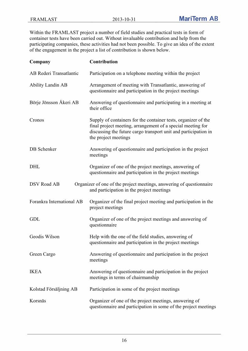
Within the FRAMLAST project a number of field studies and practical tests in form of container tests have been carried out. Without invaluable contribution and help from the participating companies, these activities had not been possible. To give an idea of the extent of the engagement in the project a list of contribution is shown below. Company Contribution AB Rederi Transatlantic Participation on a telephone meeting within the project Ability Landin AB Arrangement of meeting with Transatlantic, answering of
questionnaire and participation in the project meetings Börje Jönsson Åkeri AB Answering of questionnaire and participating in a meeting at
their office Cronos Supply of containers for the container tests, organizer of the
final project meeting, arrangement of a special meeting for discussing the future cargo transport unit and participation in the project meetings
DB Schenker Answering of questionnaire and participation in the project
meetings DHL Organizer of one of the project meetings, answering of
questionnaire and participation in the project meetings DSV Road AB Organizer of one of the project meetings, answering of questionnaire
and participation in the project meetings Forankra International AB Organizer of the final project meeting and participation in the
project meetings GDL Organizer of one of the project meetings and answering of
questionnaire Geodis Wilson Help with the one of the field studies, answering of
questionnaire and participation in the project meetings Green Cargo Answering of questionnaire and participation in the project
meetings IKEA Answering of questionnaire and participation in the project
meetings in terms of chairmanship Kolstad Försäljning AB Participation in some of the project meetings Korsnäs Organizer of one of the project meetings, answering of
questionnaire and participation in some of the project meetings

FRAMLAST 2013-10-31
17
Outokumpu Stainless AB Answering of questionnaire and participation in the project meetings
Sandvik AB Organizer of one of the project meetings, answering of
questionnaire and participation in the project meetings Sandvik SRP AB Help with one of the field studies and answering of
questionnaire Stora Enso Nymölla Answering of questionnaire and participation in some of the
project meetings Swedish Transport Agency Available for advice and participation in the project meetings,
in one of them as chairmanship Swedish Transport Financier of the project, available for advice and participation
in Administration some of the project meetings Södra Cell Answering of questionnaire and participation in some of the
project meetings University of Zilina Cooperation partner in the project, implementation of some of
the field studies and practical container tests Volvo Trucks Participation in some of the project meetings Volvo Logistics Answering of questionnaire and participation in the project
meetings Also thank you to all companies which answered to our questionnaire about demands and requirements of the future cargo transport unit: AB Elektrokoppar Akzo Nobel Arctic Paper Arizona Chemicals Billerud Bolon Mattan Borealis AB Cardo Door Carlfors Bruk DFDS Dynapac Ecophon Eka Chemical
Ericsson Ewals Cargo Expancel (Akzo Nobel) FerruForm Grycksbo Paper Holmen Paper Höganäs AB ICA Ifö Kemira Lantmännen Lantmännen Aspen McNeil
Nexans Nordanå Transport Perstorp AB Pilkington SAPA SCA SCA/Lilla Edet Scania Siemens Skanska SKF Smurfit Kappa SSAB
Stora Enso Fors Tarkett Tetra Pak Toyota Trucks (BT) Trioplast Van Dieren Vin & Sprit Volvo CE Wayne Dresser Xylem (ITT Flygt)
FRAMLAST 2013-10-31
18
2. REGULATIONS AND STANDARDS FOR CARGO SECURING EQUIPMENT This chapter contains summary information about the regulations and standards for cargo securing equipment within Europe and the international ISO standards for containers.
2.1 Sweden
Sweden had a regulation regarding equipment for cargo securing, TSVFS 1978:9, which had do be withdrawn 29th of April 2009 due to the adaptation of the European Vehicle Directive. The Swedish regulation contained among others the following requirements: - A truck as well as a trailer shall have a headboard - On vehicles with a total weight more than 7 tons there shall be lashing points resisting a force F = Qm / n, where Qm is the weight of the load and n the prescribed number of lashing points. The force is to be at least 2 tons. The interval between the lashing points is maximum 1.2 m.
2.2 Europe
There is no European directive or European regulation on required cargo securing equipment on European vehicles. However, the following non-mandatory standards are available within Europe: EN 12195-2 Load restraint assemblies on road vehicles – Safety – Part 2: Web lashing
equipment made from man-made fibres EN 12195-3 Load restraint assemblies on road vehicles – Safety – Part 3: Lashing
chains EN 12195-4 Load restraint assemblies on road vehicles – Safety – Part 4: Lashing steel
wire ropes EN 12640 Securing of cargo on road vehicles – Lashing points on commercial
vehicles for goods transportation – Minimum requirements and testing EN 12641-1 Swap bodies – Tarpaulins – Part 1: Minimum requirements EN 12641-2 Swap bodies – Tarpaulins – Part 2: Minimum requirements for
curtainsiders EN 12642:2006 Securing of cargo on road vehicles – Minimum requirements EN 283 Swap bodies – Testing EN 284 Swap bodies – Non-stackable swap bodies of class C – Dimensions and

FRAMLAST 2013-10-31
19
general requirements ISO 1496-1 Series 1 freight containers – Specification and testing – Part 1: General
cargo containers for general purposes ISO 9367-1 Lashing and securing arrangements on road vehicles for sea transportation
on Ro/Ro ships – General requirements – Part 1: Commercial vehicles and combinations of vehicles, semi-trailers excluded
ISO 9367-2 Lashing and securing arrangements on road vehicles for sea transportation
on Ro/Ro ships – General requirements – Part 2: Semi-trailers The most interesting parts from each standard are presented below. All standards are published by the national standardisation organisations in the CEN and ISO countries respectively. In Sweden the standards are available via SIS - Swedish Standards Institute.
2.2.1 EN 12195-2 -- 4
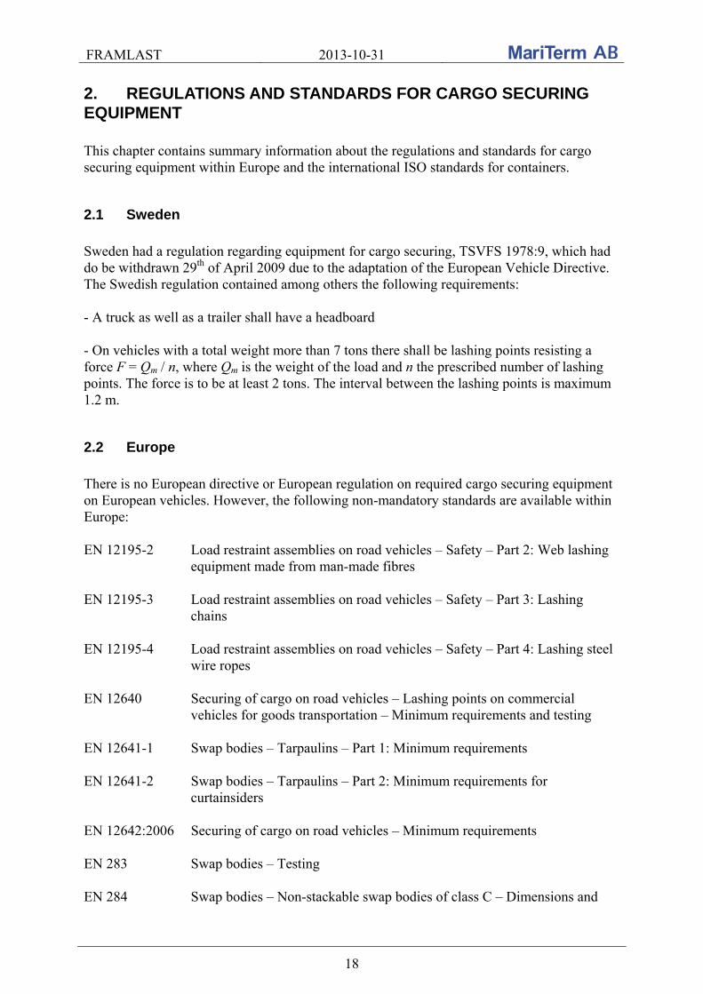
These standards for cargo securing equipment contain load restraint assemblies on road vehicles: web lashing EN 12195-2, chain lashing EN 12195-3 and wire lashing EN 12195-4. The standards contain hazards, safety requirements, testing and marking of the lashing equipment. According to EN 12195-2 “each complete web lashing, if it is intended that parts be separable, shall be marked with the following information if applicable on a label”:
lashing capacity, LC; lengths LG, LGF and LGL, in metre; standard hand force SHF standard tension force STF (daN) or winch force, based on the level for which the
tensioning device has been type tested, when designed for frictional lashing; warning: “Not for lifting!”; material of the textile webbing; manufacturer’s or supplier’s name or symbol; manufacturer’s traceability code; number and part of this European Standard, i.e. EN 12195-2; year of manufacture; elongation of textile webbing in % at LC.
End fittings, tensioning devices, tension retaining devices and tension indicators of LC ≥ 5 kN shall be marked with the manufacturer’s or supplier’s name or symbol. The value of LC shall be marked on parts with LC ≥ 5 kN in kN, on parts with LC < 5 kN in daN.
FRAMLAST 2013-10-31
20
Typical label format for web lashings Each complete lashings chain shall be marked on a metal tag with the following information:
lashing capacity, LC, in kN; standard tension force STF (daN) in daN for which the equipment is designed; for multipurpose lever blocks: designation of the maximum hand-operating force to
reach WLL; type of lashing; warning: “Not for lifting”; excluded multi-purpose lever blocks; manufacturer’s or supplier’s name or symbol; manufacturer’s traceability code; number and part of this European Standard, i.e. EN 12195-3.
Tensioning devices shall be marked at least with the manufacturer’s or supplier’s name or symbol. Each complete lashing chain or set of lashing chains shall be provided with a dated certificate stating conformity with this part of EN 12195 and giving at least the following information:
the name of the lashing chain manufacturer or supplier including date of issue of the certificate and signature;
number and part of this European Standard: EN 12195-3; identification number or symbol of the lashing chain; a description of the lashing chain, including a list of all component parts; the nominal size of chain and grade mark “8”; the nominal size (Code No) of components and grade mark “8” for types C1, C2, C3,
D1, D2, D4, D5 and D7; nominal length; lashing capacity (LC).
FRAMLAST 2013-10-31
21
Corresponding information for wire lashings is found in EN 12195-4. Wire is not further dealt with in this report.
2.2.2 EN 12640:2000
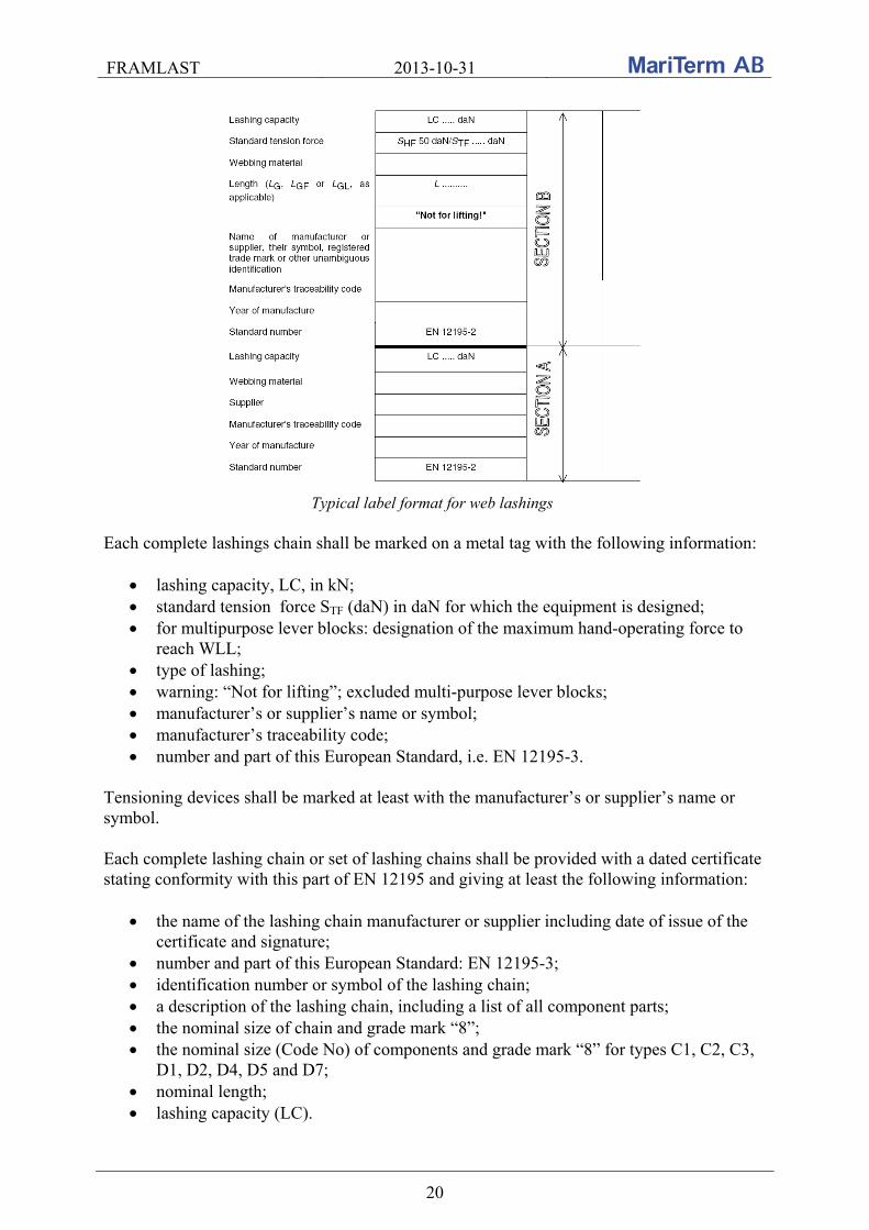
This standard, EN 12640:2000 – Securing of cargo on road vehicles – Lashing points on road commercial vehicles for goods transportation – Minimum requirements and testing – stipulates the following regarding identification:
The number of lashing points shall be determined by the highest result of the following:
length of the loading platform maximum distance between lashing points permissible tensile load
Each lashing point on the loading platform shall be designed for a permissible tensile load as specified in the table below.
Vehicles with lashing points in compliance with this standard shall be fitted with a marking plate in accordance with the figure below in a clearly visible place. The plate shall have a blue background, with white lettering and white border. The tensile load should be indicated in daN.
FRAMLAST 2013-10-31
22
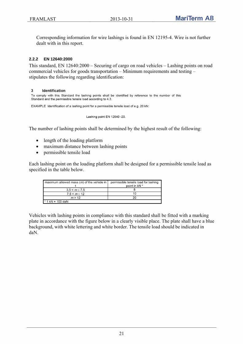
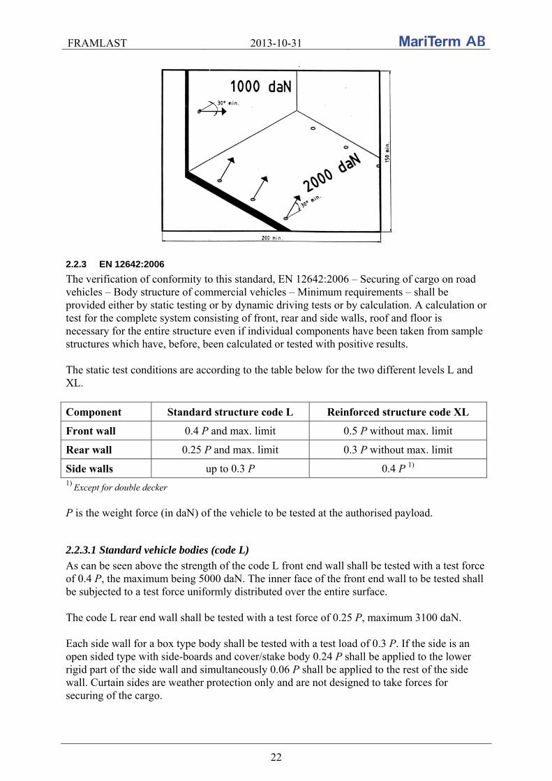
2.2.3 EN 12642:2006
The verification of conformity to this standard, EN 12642:2006 – Securing of cargo on road vehicles – Body structure of commercial vehicles – Minimum requirements – shall be provided either by static testing or by dynamic driving tests or by calculation. A calculation or test for the complete system consisting of front, rear and side walls, roof and floor is necessary for the entire structure even if individual components have been taken from sample structures which have, before, been calculated or tested with positive results. The static test conditions are according to the table below for the two different levels L and XL.
Component Standard structure code L Reinforced structure code XL
Front wall 0.4 P and max. limit 0.5 P without max. limit
Rear wall 0.25 P and max. limit 0.3 P without max. limit
Side walls up to 0.3 P 0.4 P 1)
1) Except for double decker P is the weight force (in daN) of the vehicle to be tested at the authorised payload.
2.2.3.1 Standard vehicle bodies (code L)
As can be seen above the strength of the code L front end wall shall be tested with a test force of 0.4 P, the maximum being 5000 daN. The inner face of the front end wall to be tested shall be subjected to a test force uniformly distributed over the entire surface. The code L rear end wall shall be tested with a test force of 0.25 P, maximum 3100 daN. Each side wall for a box type body shall be tested with a test load of 0.3 P. If the side is an open sided type with side-boards and cover/stake body 0.24 P shall be applied to the lower rigid part of the side wall and simultaneously 0.06 P shall be applied to the rest of the side wall. Curtain sides are weather protection only and are not designed to take forces for securing of the cargo.

FRAMLAST 2013-10-31
23
Lashing points for securing of cargo are mandatory for vehicles with curtain sides. Such fittings shall fulfil the requirements of EN 12640. After finishing the tests the body structure shall show neither permanent deformation nor other changes which would impair its intended use.
2.2.3.2 Reinforced vehicle bodies (code XL)
The strength of the front, rear and side walls of a code XL unit shall be tested with a test force of 0.5 P, 0.3 P and 0.4 P. The force shall be applied uniformly up to ¾ of the surface according to the figures below.
The test conditions of the strength in the front, rear and side walls of the code XL units Vehicle body structures fulfilling the requirements of this standard shall be marked by means of an independent sign, containing
a) conformation that the vehicle body structure complies with this standard, b) reference to this European Standard, EN 12642, c) indication of the pertinent requirement profile-Codes, L och XL, d) name of manufacturer and e) year of production.
The information shall also be integrated into the vehicle identification plate where d) and e) do not need to be repeated.
Example of marking a vehicle body in compliance with the European Standard EN 12642
FRAMLAST 2013-10-31
24
2.2.4 EN 283
According to EN 283 – Swap bodies – Testing - the testing of the strength in end walls of a swap body shall be done by static or dynamic tests to prove the ability of a swap body to withstand forces under the dynamic conditions which imply accelerations or decelerations of 2 g. In the static test each end wall shall be subjected to an internal loading of 0.4 P. The internal loading shall be uniformly distributed over the end wall under test. The test load shall be applied for 5 minutes. In the dynamic test the swap body is uniformly loaded to 1 R all over the entire floor. The wagon is then accelerated so that at the moment of impact against a stationary wagon of 80 ton a deceleration of 2 g is measured on the bottom fitting of the swap body. This impact procedure shall be carried out twice in both directions. The test of the strength of the side walls shall be carried out to prove the ability of a swap body to withstand the forces resulting from transverse accelerations during transportation. The box type swap bodies shall be subjected to an internal loading of 0.3 P. The load shall be uniformly distributed over the side wall under the test. The test load shall be applied for 5 minutes. The total loading applied to each side wall of an open sided type shall be 0.3 P applied for 5 minutes. Testing with a test rig shall be so arranged that 0.24 P is applied to the lower rigid part of the side wall and simultaneously 0.06 P is applied to the rest of the side wall. In a lateral side-up test the swap body shall be turned to rest on one longitudinal side wall so that it is supported at the bottom side rail and the corner posts and all other parts are free to deflect. The lath works shall be covered by 5 mm of plywood or equivalent to improve load distribution. The side wall shall have a load uniformly distributed by a set of weights in such a way that 0.24 P is applied to the rigid part and 0.06 P is applied to the lath works. The test for the side walls in curtainsiders shall be conducted with the swap body in the same position as mentioned above for the lateral side-up test. The entire area of the side wall shall be covered by 5 mm of plywood or elastic plates. The side wall shall have a load uniformly distributed by a set of weights in such a way that 0.24 P is applied to the full internal length by a height of 800 mm from the base and 0.06 P is applied to the remaining upper surface. No part of the flexible side wall shall deflect more than 300 mm. The following note is included in the standard regarding curtain sides: “Attention of designers is drawn to the mandatory use of cargo securing devices. The above limited deflection of 300 mm is an arbitrary test requirement only and in no way represents an acceptable degree of curtain distortion due to movement of the load. The requirements of specific authorities (e.g. for railway loading gauges) will provide the limiting deflection in service.”
2.2.5 EN 284
This standard EN 284 – Swap bodies – Non-stackable swap bodies of class C – Dimensions and general requirements – includes among others strength and design requirements for grappler arm lifting areas, steering tunnel, supporting legs etc.

FRAMLAST 2013-10-31
25
Tarpaulins and their fitting devices used for open sided swap bodies in drop sided swap bodies shall be in accordance with EN 12641-1. Tarpaulins used for curtainsider swap bodies shall be in compliance with EN 12641-2. Cargo securing devices may be provided in swap bodies as optional features, subject to agreement between manufacturer and client. However, for curtainsider swap bodies, cargo securing devices are mandatory. Where fitted, cargo securing devices shall meet the requirements of EN 12640 and EN 12642.
2.3 International
International globally valid standards are developed by ISO and when it comes to cargo securing equipment there are standards for the strength and outfitting of containers and container flat racks. There are also a standard for ferry eyes on vehicles.
2.3.1 ISO 1496-1
The tests of the strength in end walls shall according to ISO 1496-1 – Series 1 freight containers – Specification and testing – Part 1: General cargo containers for general purpose – be carried out to prove the ability of a container to withstand longitudinal external restraint under dynamic conditions of railway operations, which implies accelerations of 2 g. The container shall be subjected to an internal loading of 0.4 Pg. The tests of the strength in the side walls shall be carried out to prove the ability of a container to withstand the forces resulting from ship movement. Each side wall shall be subjected to an internal loading of 0.6 Pg. The loading in the tests above shall be uniformly distributed over each wall and the container shall show neither permanent deformation nor abnormality which will render it unsuitable for use. The strength in the container floor should be verified by maneuvering a fork lift with a minimum axle load of 2 3 630 = 7 260 kg. Each of the two wheels shall have a wheel print area of maximum 142 cm2. The wheel width shall be nominally 760 mm. The test vehicle shall be maneuvered over the entire floor area of the container. The test shall be made with the container resting on four level supports under its four bottom corner fittings, with its base structure free to deflect. Anchor points are securing devices located in the base structure of the container and the lashing points in any part of the container other than their base structure. The typical number of cargo securing devices is 16 and 12 anchor points for 40’ and 20’ containers. The typical number of lashing points is unspecified. Securing and anchor points are, however, not mandatory according to the standard. Each anchor point shall, if fitted, be designed and installed to provide a minimum rated load of 1000 kg applied in any direction. Corresponding strength in the lashing points is 500 kg.
FRAMLAST 2013-10-31
26
2.3.2 ISO 1496-5
The tests of the strength in end walls shall according to 1496-5 – Series 1 freight containers – Specification and testing – Part 5: Platform and platform-based containers – be carried out to prove the ability of a container to withstand longitudinal external restraint under dynamic conditions of railway operations, which implies accelerations of 2 g. The container shall be subjected to an internal loading of 0.4 Pg. The loading shall be uniformly distributed over the wall under test and arranged to allow free deformation of the wall. The container shall show neither permanent deformation nor abnormality which will render it unsuitable for use. Anchor points are securing devices located in the base structure of the container and the lashing points in any part of the container other than their base structure. The anchor points shall be designed and installed in such a way as to provide a total minimum securing capability at least equivalent to
0.6 P transversally 0.4 P longitudinally (for those containers having no end walls or end walls not capable
of withstanding the test described above). The typical number of cargo securing devices is 16 and 12 anchor points for 40’ and 20’ containers. The typical number of lashing points is unspecified. Each anchor point shall be designed and installed to provide a minimum rated load of 3000 kg applied in any direction. Corresponding strength in the lashing points is 1000 kg.
2.3.3 SS-ISO 9367-1
The definition of a securing point according to SS-ISO 9367-1 – Lashing and securing arrangements on road vehicles for sea transportation on Ro/Ro ships – General requirements – Part 1: Commercial vehicles and combinations of vehicles, semi-trailers excluded – is: location of a lashing point on the vehicle, suitably reinforced to withstand lashing forces. A lashing point is that part within a securing point to which a lashing may be directly attached. Securing points shall be designed to enable the road vehicle to be secured to the ship and be capable of transferring the forces from the lashings to the chassis of the road vehicle. The securing point and lashing point shall allow different angles of lashing to the ship’s deck. It is permissible to have more than one lashing point at a securing point but each lashing point shall have the strength required for a single securing point as given in the table below.
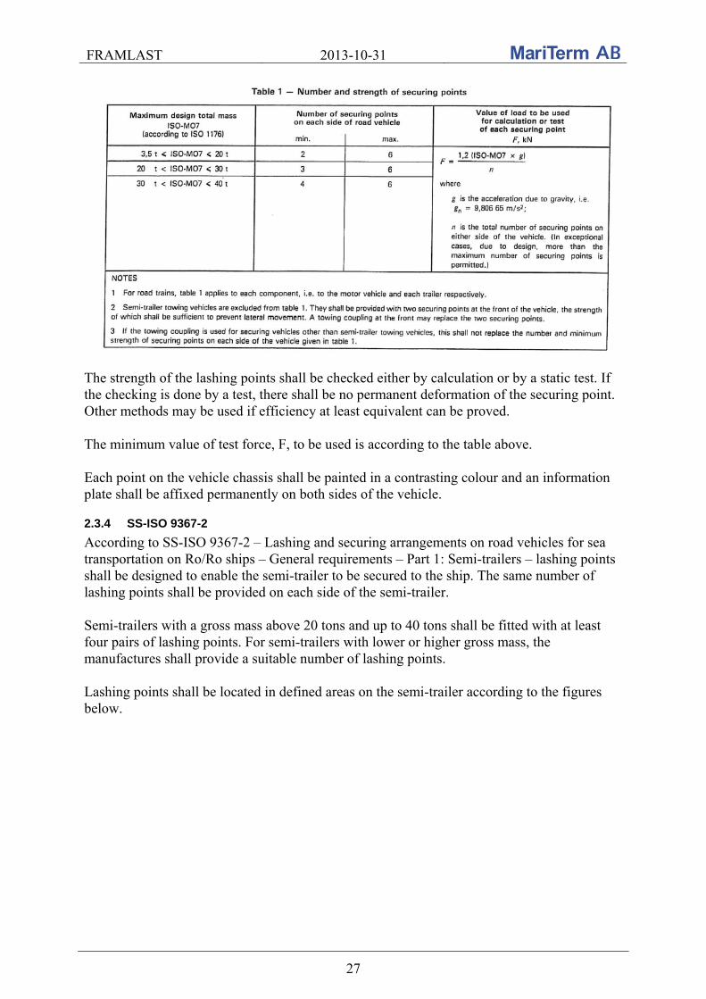
FRAMLAST 2013-10-31
27
The strength of the lashing points shall be checked either by calculation or by a static test. If the checking is done by a test, there shall be no permanent deformation of the securing point. Other methods may be used if efficiency at least equivalent can be proved. The minimum value of test force, F, to be used is according to the table above. Each point on the vehicle chassis shall be painted in a contrasting colour and an information plate shall be affixed permanently on both sides of the vehicle.
2.3.4 SS-ISO 9367-2
According to SS-ISO 9367-2 – Lashing and securing arrangements on road vehicles for sea transportation on Ro/Ro ships – General requirements – Part 1: Semi-trailers – lashing points shall be designed to enable the semi-trailer to be secured to the ship. The same number of lashing points shall be provided on each side of the semi-trailer. Semi-trailers with a gross mass above 20 tons and up to 40 tons shall be fitted with at least four pairs of lashing points. For semi-trailers with lower or higher gross mass, the manufactures shall provide a suitable number of lashing points. Lashing points shall be located in defined areas on the semi-trailer according to the figures below.

FRAMLAST 2013-10-31
28
Longitudinal positions of lashing points, dimensions in mm
Allowable vertical and transverse lashing point areas on laden semi-trailers, dimensions in mm The relation between the length l of the semi-trailer and n number of intervals for the lashing points is given by
l = 625 + (n ·1250) mm.
FRAMLAST 2013-10-31
29
The strength of the lashing points shall be checked either by calculation or by a static test. There shall be no deformation, breaks or cracks that could affect the function of the lashing points after testing to 120 kN. The value of test force, F, to be used in the static test is 120 kN. The lashing ring shall be painted in a bright color, strictly different from the background color and a marking plate shall be affixed permanently on both sides of the vehicle.

FRAMLAST 2013-10-31
30
3. COMPILATION OF EXPERIENCES FROM EARLIER PROJECTS This section contains information about existing knowledge and experiences regarding intermodal transport units from earlier research projects. Some of the projects mentioned below are DAGTRANS, HIMDAG, PROTECTED, INTERSYS, TESS, KTH, RASLA, COMBISEC and TELLIBOX. Some of the projects are carried out within SiR-C (Swedish Intermodal Transport Research Centre) which is a virtual research center initiated by the Swedish Rail Administration and the Swedish Road Administration (which now is thhe Swedish Transport Administration). The network conducts research, development and demonstration activities in intermodal transport.
3.1 DAGTRANS DAGTRANS was a project within the SiR-C consortium carried out by TFK –
TransportForsK, Chalmers University of Technology, KTH Royal Institute of Technology and TFK – Transport Research Group in Borlänge. The project was finalized in 2008. The project states that lack of a standard for advanced information systems is a barrier for establishing sustainable intermodal systems for temperature and quality-sensitive shipments. With today's cargo transport units, it is often difficult to make rational handling and transport of groceries and highly processed goods. Furthermore half the amount of groceries presents temperature-sensitive goods (cooling and freezing) for which special rules apply for shipments. Another problem, environment-related, is that the cooling units often are diesel powered. Therefore there is a need to develop new cargo transport units and systems that meet the demands of supermarkets and shippers of highly processed goods. The producers are reluctant to transport the frozen (and cooled) goods in wagon-loads, since there are neither wagons nor cargo transport units capable of handling the specific requirements for this type of goods. Further it is stated that the supply of cargo transport units for both rear and side loading, which works for both loading at industrial sidings and in terminals, is a limiting factor for intermodal transport development. The length of cargo transport units corresponding to a semi-trailer, with a length of 13.6 m, is a standard module that is expected to be dominant for the foreseeable future. Current intermodal transport is locked to the terminals. Interference or lack of capacity at one terminal can’t easily manage to be moved to an alternate location to enable the goods arriving on time. Flexibility for large and small volumes and reloading of cargo transport units with temperature-sensitive goods must be possible. The intermodal transport is in planning terms favored by customized and advanced IT support. Forwarders and haulers require traceability of consignments and cargo transport units that in turn manage and optimize their flows and resources. To get a cost effective way to coordinate the flow and offer conveyors high resource utilization, standardized intermodal IT support for the identification, traceability and control of time and / or temperature-sensitive shipments and cargo transport units are required in intermodal transport systems. More

FRAMLAST 2013-10-31
31
complex transport systems require an increased focus on utilization of wagons, cargo transport units and terminals over time. A continuation study is expected to show how intermodal transport can be made more attractive and offer new logistical opportunities through new and further development of cargo transport units such as allowing easier / faster loading and unloading.
3.2 HIMDAG The HIMDAG project was performed within the SiR-C consortium and the final report was published in 2011. The HIMDAG project considered the semi-trailer as the most common CTU of cross-border intermodal transport for tempered cargo, and also the most interesting CTU for intermodal transport of groceries from the range of existing CTUs that is available on the market. This was, incidentally, the same assessment as Coop made in conjunction with the Coop-train. The project stated that transports of groceries and other high valued goods are difficult to handle rationally, when common transport units are to be used. One way of increasing the use of intermodal transports for high valued goods is to develop a transport unit concept customized for the requirements on comfort, cargo safety, inner climate and manageability, declared by the cargo owner.
3.3 TESS
In the TESS project, which focuses on temperature-sensitive cargo, it is concluded that the availability of electricity for chillers is one of the biggest problems with such transports, performed in combined transport modes on railway.
3.4 PROTECTED MariTerm AB has studied the security initiatives developed for the prevention of crimes exposed to the transport sector. This study was performed as a research project initiated by MariTerm within the SiR-C consortium. The final report was published in 2011 by the title “PROTECTED – Security inom Kombitransporter” (Security within Intermodal Transports). The knowledge obtained through this project has been valuable for determining the requirements linked to the cargo transport unit in regard to the fulfillment of available security initiatives. This experience has been usable through the work with the FRAMLAST project. Since the 11th of September 2001 the world has become deeply affected by the consequences associated with the terrorist attacks to the World Trade Center in New York and the United States of America. Before this event, the security measures taken against unauthorized access to ships, airplanes and other vehicles operating within the transport sector were not dimensioned for hindering sophisticated take-overs from being realized. However, terrorism has been present for a long period of time but the attacks occurred in 2001 have given us a new dimension of what can happen if sufficient actions aren’t established. The transport sector is simultaneously

FRAMLAST 2013-10-31
32
highly exposed to terrorism since transportation in most cases is a necessary part of the intended action. With this in mind, international organizations as well as national governments have introduced strengthened regulations regarding the security within the transport sector. In addition to terrorism, the transport sector is facing other kinds of threats such as smuggling, theft and sabotage, by which the frequency seems to increase for each year. Crimes like these are costly to prevent but since the statistics is indicating that the economic losses for passivity may be far higher in an overall perspective, prevention must be enforced.
3.4.1 Knowledge achieved by the project
For the determination of which requirements the individual cargo transport unit must comply for the fulfillment of regulations stated in various security initiatives, one must be aware of the divergent interest that constitutes and form these standards. For example, security initiatives provided by a governmental authority may prioritize actions that reduce crimes against the society, like terrorism and smuggling, while security initiatives initiated by transport and cargo owners may prioritize actions taken against theft and sabotage. Differences in the underlying aim of various initiatives create difficulties for the proper application of a universal security level within the transport sector. At the same time, some initiatives are mandatory while others are optional. This may lead to the situation where transport and cargo owners may need to certify their activities in several steps and by different standards, for achieving the level of security requested within their field. For global transports the security initiatives studied within the PROTECTED project are mainly focused on container units, which is natural since most of these transports are performed by containers. For other kinds of cargo transport units, regulations regarding security requirements are provided in a much smaller scale. It is also obvious that few security initiatives are focusing on the prevention of intrusion followed by a crime intended for stealing. Since these crimes are thoroughly associa-ted to the construction of the cargo transport unit, security initiatives determining requirements for the prevention of these crimes may therefore be interesting input to the FRAMLAST project. From this point of view a security initiative called TAPA, Transported Asset Protection Association, will be further described below.
3.4.2 Security requirements stated by the TAPA-initiative
TAPA is an association of security professionals and related business partners from various manufacturers and transportation companies who cooperate for the purpose of addressing the emerging security threats that are common to the relevant industries. The aim of the Association is to provide a forum for responsible managers to share professional information and receive benefits in return. The association was founded by a group of manufacturers transporting high valued cargo, such as Intel, Compaq and SUN, but as when the technology market grew more industries became members. Today TAPA has developed security initiatives aimed for the prevention of theft against the transport sector, continuously working for their vision of receiving global attention and thereto set a global security level for certain types of transports.
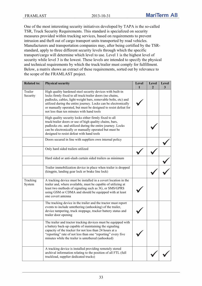
FRAMLAST 2013-10-31
33
One of the most interesting security initiatives developed by TAPA is the so-called TSR, Truck Security Requirements. This standard is specialized on security measures provided within trucking services, based on requirements to prevent intrusion and theft out of cargo transport units transported by road vehicles. Manufacturers and transportation companies may, after being certified by the TSR-standard, apply to three different security levels through which the specific transport/cargo will determine which level to use. Level 1 is the highest level of security while level 3 is the lowest. These levels are intended to specify the physical and technical requirements by which the truck/trailer must comply for fulfillment. Below, a matrix shows an extract of these requirements, sorted out by relevance to the scope of the FRAMLAST project. Related to: Physical security Level
1 Level
2 Level
3 Trailer Security
High quality hardened steel security devices with built-in locks firmly fixed to all truck/trailer doors (no chains, padlocks, cables, light-weight bars, removable bolts, etc) and utilized during the entire journey. Locks can be electronically or manually operated, but must be designed to resist defeat for not less than ten minutes with hand tools
High quality security locks either firmly fixed to all truck/trailer doors or use of high quality chains, bars, padlocks etc. and utilized during the entire journey. Locks can be electronically or manually operated but must be designed to resist defeat with hand tools
Doors secured in line with suppliers own internal policy
Only hard sided trailers utilized
Hard sided or anti-slash curtain sided trailers as minimum
Trailer immobilization device in place when trailer is dropped (kingpin, landing gear lock or brake line lock)
Tracking System
A tracking device must be installed in a covert location in the trailer and, where available, must be capable of utilizing at least two methods of signaling such as 3G, or SMS/GPRS using GSM or CDMA and should be equipped with at least one covert antenna
The tracking device in the trailer and the tractor must report events to include untethering (unhooking) of the trailer, device tampering, truck stoppage, tracker battery status and trailer door opening
The trailer and tractor tracking devices must be equipped with a battery back-up capable of maintaining the signaling capacity of the tracker for not less than 24 hours at a “reporting” rate of not less than one “reporting” every five minutes while the trailer is untethered (unhooked)
A tracking device is installed providing remotely stored archival information relating to the position of all FTL (full truckload, supplier dedicated trucks)
FRAMLAST 2013-10-31
34
As can be concluded through the requirements stated in the TSR-initiative by TAPA, special attention should be carried out regarding the construction of the truck and trailer when transports are performed at level 1 and 2. Such constructional requests are affecting the development of future cargo transport units since these aspects must be incorporated early in the manufacturing chain, customizing the products according to what the market is demanding. Generally, common cargo transport units intended for utilization in transports performed at level 3 may quite easily be modified for compliance with the TAPA TSR regulations while modifications for common cargo transport units intended for use at level 1 and 2 would require a lot more efforts. Such modifications would surely also become costly, followed by the expenses associated to modifications of this scale. Followed by the requirements in the TSR-initiative one can determine that accurate doors and locks are important parts for the security measures regarded to the constructional requests on the cargo transport unit. At the same time it seems to be natural requiring that transports performed at level 1 and 2 are done by the use of hard sided trailers, but simultaneously no guidelines are given regarding the construction of the superstructure. Digging into the TSR-initiative, hard sided trailers are defined as “trailers whose sides, floor and top are constructed of metal or other solid material”. As no other definition is given it should be presumed that, based on the focus laid on the door and lock arrangements, the solid superstructure should be considered not to be the weakest part of the overall structure, thereby not necessary for further specification. Besides the superstructure considerations, monitoring devices such as positioning and report systems seem to be important parts as complement to the physical shelter against crimes. Through this, the cargo transport unit must be designed for the ability to house such equipment. Even though the TAPA TSR-initiative is developed for the prevention of theft and intrusion threats against trailers, the requirements may also have effects on other kinds of crimes such as terrorism and smuggling. Locking unauthorized persons out from access to a cargo transport unit is essential for the prevention of these crimes and TAPA would therefore be a good base for future transformation into a universal security standard, followed by necessary extension and improvements. With this in mind the requirements stated by TAPA are probably hinting the future direction of developments and requests on forthcoming cargo transport units, strongly supported by both cargo and transport owners.
3.5 INTERSYS
The INTERSYS project was started in 2008 and was performed as a research project within the SiR-C consortium. The purpose of the INTERSYS project was to map the RFID (radio-frequency identification) tools and technologies available for implementation in intermodal freight transport systems. Security and increased demands for secure transport systems has been mentioned as one of the key reasons for implementing RFID and security will continue to be a central aspect of international transport. There is no doubt that RFID has some positive effects on intermodal freight transport. Identification of goods and physical resources can be made efficient using Auto-ID and RFID. The value added by using the technology can be found in both the physical processes

FRAMLAST 2013-10-31
35
and the administrative routines in intermodal freight transport. The benefits will not solely be the result of RFID:
Increased possibilities for track and trace in intermodal transport chains Correct charging for the use of common resources Proactive maintenance of mobile resources (wagons, vehicles and vessels) based on
input from trackside readers and detectors More efficient physical handling of load units, and goods handling equipment Verification of the position and handling of transport units in terminals and shunting operations.
A large part of the problems associated with intermodal freight transport are related to uncertainty and the risks that the goods will not be delivered on-time. These problems are often a consequence from the lack of information support, both from a planning and a communication perspective. The complexity of the intermodal freight transport system depends on the many physical constraints to be found in the intermodal freight transport system. These constraints include the interfaces between the different intermodal operators, the customer and the forwarder. It also means that there are information interfaces that have to be over-bridged within planning and execution but also in reporting the different stages in the transport process. To handle the complexity of the transport system, RFID will contribute to a solution where the goods can be identified, thus providing additional information on the transportation process. RFID will also decrease some of the uncertainty found in the physical flow of goods and load units in intermodal freight transport. RFID single-handedly will however not provide the solution to intermodal freight transport. Therefore, RFID should be regarded as an enabler for services and information solutions that may add value to both operators and transport users. RFID may also provide a solution to the lack of flexibility that can be found in many intermodal transport operations. Lacking flexibility in the intermodal transport system makes small scale solutions within intermodal transport unprofitable. This means that in areas where the quantities of goods are small, customers will have fewer opportunities to use intermodal freight transport. To increase the flexibility in intermodal transport, several measures have to be taken, not only within information handling but also developing technologies for handling physical equipment. For operational problems, if successful, RFID will provide:
Efficient identification of load units (reading and storage) to avoid erroneous handling of items, increased productivity and security
Access to detailed information on the goods handling process and during transport (potential damage and accidents during handling)
Efficient loading and unloading (vessels and load units) Efficient coordination or fixed and mobile resources – internal planning and
forecasting
FRAMLAST 2013-10-31
36
Still, there are no clear answers. However, the problems and challenges within intermodal freight transport do correspond to the expected benefits of RFID. Whether RFID or other technologies will be the answer to these problems will be analysed in the further studies of the INTERSYS project. No further information is found about the INTERSYS project.
3.6 KTH - Evaluation of weak links in intermodal transport chains
In the KTH project “Evaluation of weak links in intermodal transport chains” it is concluded that cargo may be damaged during terminal handling or when moisture sensitive goods are transported in combined transport modes on railway. The reason for cargo damage caused by moisture during railway transports seems to be that commonly used transport units are not suitable for high speeds and certainly not when the units are transported with the rear end in the forward direction. This issue will be highlighted even more if the allowed railway speed will increase in the future. Some relevant companies and participants within this project were asked about experiences of problems with moisture entering trailers during intermodal transport by rail but nobody have heard of this problem.
3.7 RASLA
The project was ended in 2001 and was initiated by the Transport Industry Association and was directed and carried out by MariTerm-TISAB. The project states that insufficient securing of cargo during transports gives a risk for damages to both cargo and vehicles as well as persons, working in the chain of transports or is involved in another way, such as being a road user. At inspections of road vehicles carried out by police and coastguard there are often many vehicles with insufficient secured cargo. At discussions with personnel involved in loading and securing of cargo the defectiveness is often explained by that it is difficult and costly to secure with the equipment present on the vehicles today. Even if the regulations are rather clear, the practical conditions to do a proper work are missing. This is a problem noted among others by representatives for the industry and transport sector. The Federation of Swedish Industries took the initiative to a project with aim to show examples of equipment giving lorry drivers and other personnel involved possibility to make the work with the cargo securing easier and quicker. The project has been called “Equipment for rational securing of cargo on vehicles – RASLA”. To focus on the problems to secure cargo in a rational way with existing equipment, a number of different types of cargo loaded on cargo transport units have been described. The following securing functions have been identified and are desired from a rationalising point of view.
Flexible, strong blocking device forward at an optional place in the fore part of the vehicle

FRAMLAST 2013-10-31
37
Blocking sideways at an optional place on platforms of aluminium or steel sheet Possibility to block garbage containers forward and sideways Possibility to block cargo sideways against vehicles’ sides having a defined strength Marking on the vehicle of the strength of the vehicle’s sides Flexible placement of the lashings lengthways Larger amount of lashing points inside and outside the sideboards. Stronger lashing points making it possible to utilise the full strength also of chain
lashings Clear marking of the strength of the lashing points Be able to secure palletised cargo in a box type vehicle without lashing points on the
platform Securing keeping soft and vibrating cargo in place Automatic securing of timber, eliminating the need of throwing the chain lashings
over the cargo Automatic securing of general cargo
Existing equipment for cargo securing have been surveyed by contacting suppliers of vehicles, cargo transport units and cargo securing equipment, visiting fairs and by searching on the Internet. When equipment for the identified securing functions for cargo securing have been missing or found insufficient, proposals of equipment with the required functions have been worked out within the project. Examples of such equipment are:
A side beam for flexible cargo securing with possibility to place lashing equipped with standard hooks anywhere along the platform, inside as well as outside the sideboards
Arrangements for strong, flexible blocking lengthways Curtain sided vehicle combined with sideboards giving less deflection of the sides
compared to a conventional cover/stake superstructure Automatic cargo securing hood for distribution vehicles Possibility to tighten conventional web lashing tensioners by machinery equipment
Some of the explored equipment has been built into a demonstration and cargo securing vehicle. This vehicle will be used at exhibitions and for cargo securing training. Lack of time and/or suitable cargo securing equipment lead to insufficient secured cargo in many vehicles. This in turn leads to stress symptoms by many lorry drivers, who are aware of the defects and who are worried about what may happen. To get an improved cargo securing the following cargo securing improving actions are proposed:
1. Establishment of rules and regulations stating that the sides of vehicles shall be built with strength according to the standards SS-EN 283 and prEN 12642.
2. Establishment of rules and regulations stating that vehicles shall be equipped with a
side beam for optional fastening of lashings along the platform. For vehicles with sideboards there shall be a possibility for optional fastening of lashings inside as well as outside the sideboards.
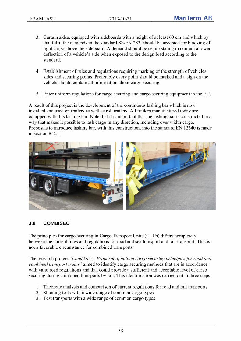
FRAMLAST 2013-10-31
38
3. Curtain sides, equipped with sideboards with a height of at least 60 cm and which by
that fulfil the demands in the standard SS-EN 283, should be accepted for blocking of light cargo above the sideboard. A demand should be set up stating maximum allowed deflection of a vehicle’s side when exposed to the design load according to the standard.
4. Establishment of rules and regulations requiring marking of the strength of vehicles’
sides and securing points. Preferably every point should be marked and a sign on the vehicle should contain all information about cargo securing.
5. Enter uniform regulations for cargo securing and cargo securing equipment in the EU.
A result of this project is the development of the continuous lashing bar which is now installed and used on trailers as well as roll trailers. All trailers manufactured today are equipped with this lashing bar. Note that it is important that the lashing bar is constructed in a way that makes it possible to lash cargo in any direction, including over width cargo. Proposals to introduce lashing bar, with this construction, into the standard EN 12640 is made in section 8.2.5.
3.8 COMBISEC
The principles for cargo securing in Cargo Transport Units (CTUs) differs completely between the current rules and regulations for road and sea transport and rail transport. This is not a favorable circumstance for combined transports. The research project “CombiSec – Proposal of unified cargo securing principles for road and combined transport trains” aimed to identify cargo securing methods that are in accordance with valid road regulations and that could provide a sufficient and acceptable level of cargo securing during combined transports by rail. This identification was carried out in three steps:
1. Theoretic analysis and comparison of current regulations for road and rail transports 2. Shunting tests with a wide range of common cargo types 3. Test transports with a wide range of common cargo types
FRAMLAST 2013-10-31
39
The CombiSec project was carried out within the SiR-C consortium. The project was possible to be carried out thanks to the work of a very large number of industry partners which has participated in the project. In practice, the securing of the goods in CTUs is normally done according to the principles used for road transport. If blocking is not possible, which is the case in most curtainsiders and open flatbed trailers, top-over lashings are by far the most commonly used method for cargo securing. However, generally the UIC (International Union of Railways) Loading Guidelines disqualifies indirect fastenings (top-over lashings) from being used to prevent sideways sliding. Within the project, shunting tests were performed in accordance with UIC Loading Guidelines with 19 cargo transport units supplied by the projects industry representatives. The cargo securing fulfilled the road regulations in 13 of the 19 units only. None of the units were in compliance with the instructions in the UIC Loading Guidelines. Despite this, cargo movements in the longitudinal direction were very limited, and it could be concluded that it is sufficient to secure cargo in cargo transport units for combined road/rail transports according to the road regulations as long as shunting is carried out at the prescribed maximum speed of 4 km/h. During the project, the securing of a wide range of cargoes was documented during test transports of more than 100 units. The selection of units was carried out by two different principles:
1. Multiple units with identical cargo units were documented by industry representatives in the project, throughout the whole transport chain on selected relations.
2. Random units where selected at rail terminals and documented prior to and after the
rail haulage. For each unit the cargo type and properties, type and classification of the cargo transport unit as well as the means of cargo securing were recorded. The original position of the cargo was marked on the platform floor and any movement was noted upon arrival at the destination. The following main conclusions have been reached based on the results of the test transports:
In most inspected units, no signs of significant accelerations in any direction could be detected except in some units in one and the same train, which probably was exposed to large shunting speeds.
There were no indications of significant accelerations in the transverse direction in any of the inspected units.
There is a significant wandering effect for unlashed cargo during intermodal transports by rail due to vibrations. The movement of the cargo occurred randomly.
The curtain sides of XL trailers have in these test transports proved to be able to safely
contain the cargo within the unit without showing any noticeable deflection, even when the cargo was unlashed.
FRAMLAST 2013-10-31
40
Indirect lashings (top-over lashings) may be used to safely secure cargo during rail transports.
In all cases, when properly applied, the securing principles for cargo securing during
road transports may serve as safe guidelines also for combined transports by rail. Based on the findings in the CombiSec project and the conclusions above the principles set out in the “European Best Practice Guidelines on Cargo Securing for Road Transport” is sufficient also for combined rail transports. It is thus recommended that the UIC Loading Guidelines are complemented with the inclusion of these principles. It is, however, important to bear in mind that a design acceleration in longitudinal direction of 0.5 g (about 5 m/s2) is based on shunting speeds of maximum 4 km/h. To avoid that cargo moves uncontrolled due to vibrations during the rail part of the transports it is recommended that special requirements are provided for cargo securing arrangements to avoid such movements. If the UIC Loading Guidelines are complemented according to these recommendations it is also recommended to approach CEN/TC 168 to get the basic design accelerations for combined rail transports altered to be in line with the accelerations for road transports. This is important not to jeopardize the future increase of combined rail transports as the cargo securing standard EN 12195-1 (2010) might be used to form the bases for a future cargo securing directive within the European Community. Read about the continuation of the CombiSec project in chapter 9.
3.9 TELLIBOX
The TelliBox project - InTELLIgent megaswapBOX for advanced intermodal freight transport - was an EU-funded project running from 2008-2011. The purpose of the project was to launch an all-purpose loading unit on the intermodal market. The scientific aim was to develop a MegaSwapBox that can be used for road, rail and sea transport with the following main advantages:
Trimodal (for road, rail and sea transport) Stackability Top-handable Inside height of 3 m Loading capacity of 100 m³ Length of 45’ Openable 3 sides Pilfer and theft-proof Suitable for use on existing low-loader railway wagons Usable in road transport thanks to a suitably adapted chassis

FRAMLAST 2013-10-31
41
The TelliBox consortium consisted of: RWTH Aachen University (Germany), Ewals Cargo Care B.V. (The Netherlands), CTL Logistics S.A. (Poland), Wecon GmbH (Germany), Wesob Sp. z.o.o. (Poland), HRD Trailer-Engineering GmbH (Germany), University of Zilina (Slovakia), Wincanton GmbH (Germany), ICM Intermodal Concepts & Management AG (Switzerland) and the European Intermodal Association (Belgium). A questionnaire was distributed to almost 60 companies and 32 answers (19 from Germany, 7 from Slovakia, 2 from Czech Republic and one from each of France, Hungary, Slovenia and United Kingdom) to analyse were received. The majority of the companies were manufac-turers. 42 % of the respondents were not satisfied with the cargo transport units used today. Among the main disadvantages was:
Difficult handling operation Impossible stackability The universality and limited size High purchase price
The most important part of the questionnaire was a question which the respondents could express their opinion on importance of cargo transport unit characteristics from 0 to 10. The average values of MegaSwapBox characteristics are given below:

FRAMLAST 2013-10-31
42
Charateristics Parameters Average Dispersion
Internal height 3 m 8.78 1.68 Internal width 2.48 m 8.53 1.74 Length 13.65 m 8.94 1.40 Payload 24 – 25 ton 7.69 1.89 Cargo capacity 100 m3 8.63 1.62 Stackability 1 + 4 stacks 5.13 2.30 Required speed on railway 140 km/h 5.74 2.67 1 openable side door (left side) - 5.07 2.87 2 openable side doors - 5.83 3.12 Liftable top - 5.48 3.08 Bimodality – road/railway - 8.32 1.49 Trimodality – road/railway/water - 6.54 2.64 Safety – lockable door - 8.38 1.72 In below table a comparison of technical and technological parameters of UTIs is made. “+” means standard, “0” purpose-built and “-“ none.
Container
ISO 1A Container
HC 45’ Swap body (series A)
Semi-trailer (Jumbo)
MegaSwapBox (assumed)
Trimodal + + - - +
Stackable + + 0 - +
Handling from top (corner fittings)
+ + - - +
Cargo volume 100 m3 - - + + +
3 m internal height - - + + +
Loading facilities from three sides
0 0 0 + +
Safety of cargo (pilferage/theft)
+ + 0 0 +
Liftable top 0 0 0 + +
A comparison between different CTUs is made below.
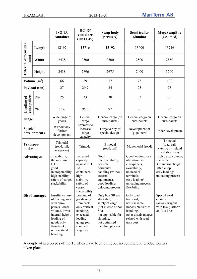
FRAMLAST 2013-10-31
43
ISO 1A
container
HC 45’ container (UNIT 45)
Swap body (series A)
Semi-trailer (Jumbo)
MegaSwapBox (assumed)
Ext
ern
al d
imen
sion
s (m
m)
Length 12192 13716 13192 13600 13716
Width 2438 2500 2500 2500 2550
Height 2438 2896 2675 2400 3200
Volume (m3) 66 89 77 75 100
Payload (ton) 27 29.7 34 25 25
Loa
din
g of
eu
ro-p
alle
ts
No 25 33 30 33 33
% 85.6 95.6 97 96 95
Usage Wide range of
goods General cargo
General cargo (on euro-pallets)
General cargo on euro-pallets
General cargo on euro-pallets
Special developments
Without any further
development
Attempts to increase
cargo capacity
Large variey of special designs
Development of “gigaliners”
Under development
Transport modes
Trimodal (road, rail, waterway)
Trimodal Bimodal
(road, rail) Monomodal (road)
Trimodal (road, rail,
waterway – inland and short sea)
Advantages availability, the most used UTI, good interoperability, high stability, safety of cargo, stackability
Increased capacity against ISO 1A containers, high stability, safety of cargo, stackabillity
Good interoperability, possible horizontal handling (without external equipment), good loading/ unloding process
Good loading area utilisation with euro-pallets, availability, no need of terminals, easy loading/ unloading process, flexibility
High cargo volume, stackable, 3 m internal height, liftable top, easy loading/ unloading process
Disadvantages Insufficient use of loading area with euro-pallets, lower volume, lower internal height, loading of goods only from back, only vertical handling
Loading of goods only from back, only vertical handling, exceeded loading gauge (on standard wagons)
Only box SB are stackable, safety of cargo (not in case of box SB), not applicable for shipping, not optimised handling process
Only road transport, not stackable, impossible vertical handling, other disadvantages related with road transport
Special road chassis, railway wagons with low platform on C45 lines
A couple of prototypes of the TelliBox have been built, but no commercial production has taken place.
FRAMLAST 2013-10-31
44
4. MAPPING OF CURRENT PARAMETERS FOR TRAILERS The mapping carried out within the FRAMLAST project of current parameters for trailers is presented in this chapter.
4.1 Visits
During the project study visits at the Port of Åhus, Port of Gothenburg, Cronos Containers, Schmitz Cargobull, Börje Jönsson Åkeri and Ability Landin AB with Transatlantic connected by phone, has been carried out. A meeting has been arranged in Helsingborg with representatives from Krone and some important information was found out during a cargo securing training focusing on vehicle superstructures. Visits at the fair trades in Munich and Hannover and at a seminar “High Capacity Transport, infrastructure and road safety” have also been performed. Reports from the visits are found in Appendixes to this report.
4.2 Information and data collected from visits
The collected information and data pertaining trailers from the visits at Schmitz Cargobull and Börje Jönsson Åkeri and the meeting with Krone is summarized in the different dimension categories according to below.
4.2.1 Length
The current standard inner length for trailers is 13.6 m. The trailer manufacturers believe that this length is here to stay in short and medium term. Trials are carried out in Germany with 14.9 m long trailers that fulfills the requirement of the total length of 18.75 m for truck plus trailer. It also fulfills the requirements for turning radius. A trailer length of 14.9 m does, however, not fit into existing railway wagons for combined transport trains and this is unfortunate. The modular system of length 25.25 is approved in Sweden, Finland, the Netherlands, Norway and Denmark and is based on combining the loading lengths of 7.82 m and 13.6 m in a road train. Börje Jönsson Åkeri has been one of the driving forces behind the appearance of the 25.25 m modular system. The system has its origin in combining the max allowed European vehicle length of a road train of 18.75 m and the maximum allowed Swedish vehicle length of 24 m. As a compromise it was agreed that it should be allowed to have road train length of 25.25 m if the vehicles consist of two units with the length corresponding to one swap body (7.82 m) and one trailer (13.6 m). In the figure below different vehicle combinations are shown.
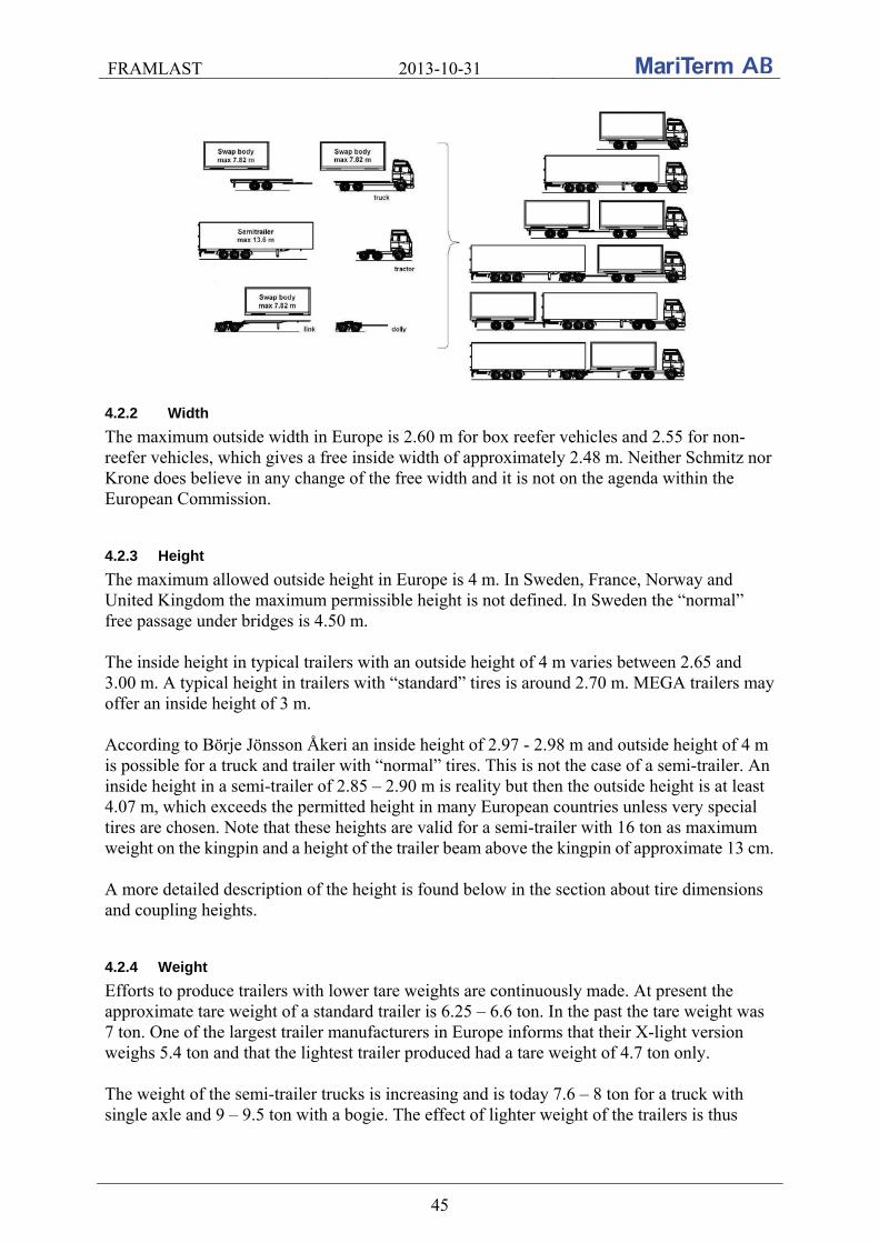
FRAMLAST 2013-10-31
45
4.2.2 Width
The maximum outside width in Europe is 2.60 m for box reefer vehicles and 2.55 for non-reefer vehicles, which gives a free inside width of approximately 2.48 m. Neither Schmitz nor Krone does believe in any change of the free width and it is not on the agenda within the European Commission.
4.2.3 Height
The maximum allowed outside height in Europe is 4 m. In Sweden, France, Norway and United Kingdom the maximum permissible height is not defined. In Sweden the “normal” free passage under bridges is 4.50 m. The inside height in typical trailers with an outside height of 4 m varies between 2.65 and 3.00 m. A typical height in trailers with “standard” tires is around 2.70 m. MEGA trailers may offer an inside height of 3 m. According to Börje Jönsson Åkeri an inside height of 2.97 - 2.98 m and outside height of 4 m is possible for a truck and trailer with “normal” tires. This is not the case of a semi-trailer. An inside height in a semi-trailer of 2.85 – 2.90 m is reality but then the outside height is at least 4.07 m, which exceeds the permitted height in many European countries unless very special tires are chosen. Note that these heights are valid for a semi-trailer with 16 ton as maximum weight on the kingpin and a height of the trailer beam above the kingpin of approximate 13 cm. A more detailed description of the height is found below in the section about tire dimensions and coupling heights.
4.2.4 Weight
Efforts to produce trailers with lower tare weights are continuously made. At present the approximate tare weight of a standard trailer is 6.25 – 6.6 ton. In the past the tare weight was 7 ton. One of the largest trailer manufacturers in Europe informs that their X-light version weighs 5.4 ton and that the lightest trailer produced had a tare weight of 4.7 ton only. The weight of the semi-trailer trucks is increasing and is today 7.6 – 8 ton for a truck with single axle and 9 – 9.5 ton with a bogie. The effect of lighter weight of the trailers is thus
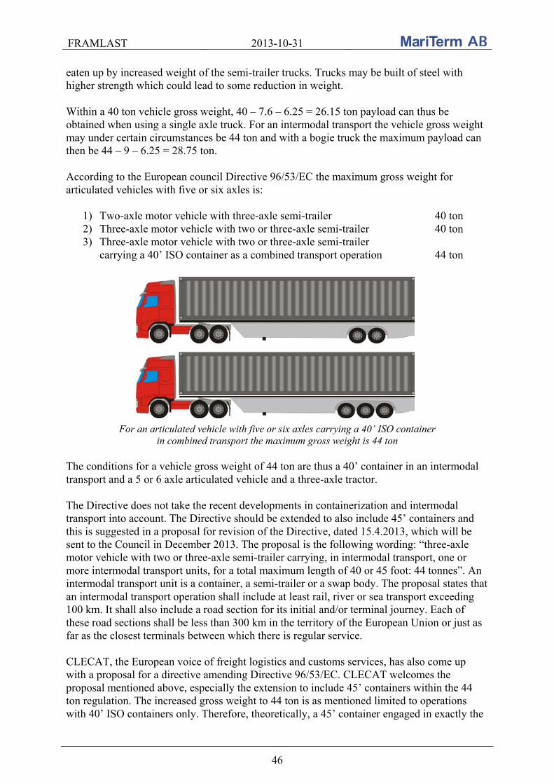
FRAMLAST 2013-10-31
46
eaten up by increased weight of the semi-trailer trucks. Trucks may be built of steel with higher strength which could lead to some reduction in weight. Within a 40 ton vehicle gross weight, 40 – 7.6 – 6.25 = 26.15 ton payload can thus be obtained when using a single axle truck. For an intermodal transport the vehicle gross weight may under certain circumstances be 44 ton and with a bogie truck the maximum payload can then be 44 – 9 – 6.25 = 28.75 ton. According to the European council Directive 96/53/EC the maximum gross weight for articulated vehicles with five or six axles is:
1) Two-axle motor vehicle with three-axle semi-trailer 40 ton 2) Three-axle motor vehicle with two or three-axle semi-trailer 40 ton 3) Three-axle motor vehicle with two or three-axle semi-trailer
carrying a 40’ ISO container as a combined transport operation 44 ton
For an articulated vehicle with five or six axles carrying a 40’ ISO container in combined transport the maximum gross weight is 44 ton
The conditions for a vehicle gross weight of 44 ton are thus a 40’ container in an intermodal transport and a 5 or 6 axle articulated vehicle and a three-axle tractor. The Directive does not take the recent developments in containerization and intermodal transport into account. The Directive should be extended to also include 45’ containers and this is suggested in a proposal for revision of the Directive, dated 15.4.2013, which will be sent to the Council in December 2013. The proposal is the following wording: “three-axle motor vehicle with two or three-axle semi-trailer carrying, in intermodal transport, one or more intermodal transport units, for a total maximum length of 40 or 45 foot: 44 tonnes”. An intermodal transport unit is a container, a semi-trailer or a swap body. The proposal states that an intermodal transport operation shall include at least rail, river or sea transport exceeding 100 km. It shall also include a road section for its initial and/or terminal journey. Each of these road sections shall be less than 300 km in the territory of the European Union or just as far as the closest terminals between which there is regular service. CLECAT, the European voice of freight logistics and customs services, has also come up with a proposal for a directive amending Directive 96/53/EC. CLECAT welcomes the proposal mentioned above, especially the extension to include 45’ containers within the 44 ton regulation. The increased gross weight to 44 ton is as mentioned limited to operations with 40’ ISO containers only. Therefore, theoretically, a 45’ container engaged in exactly the
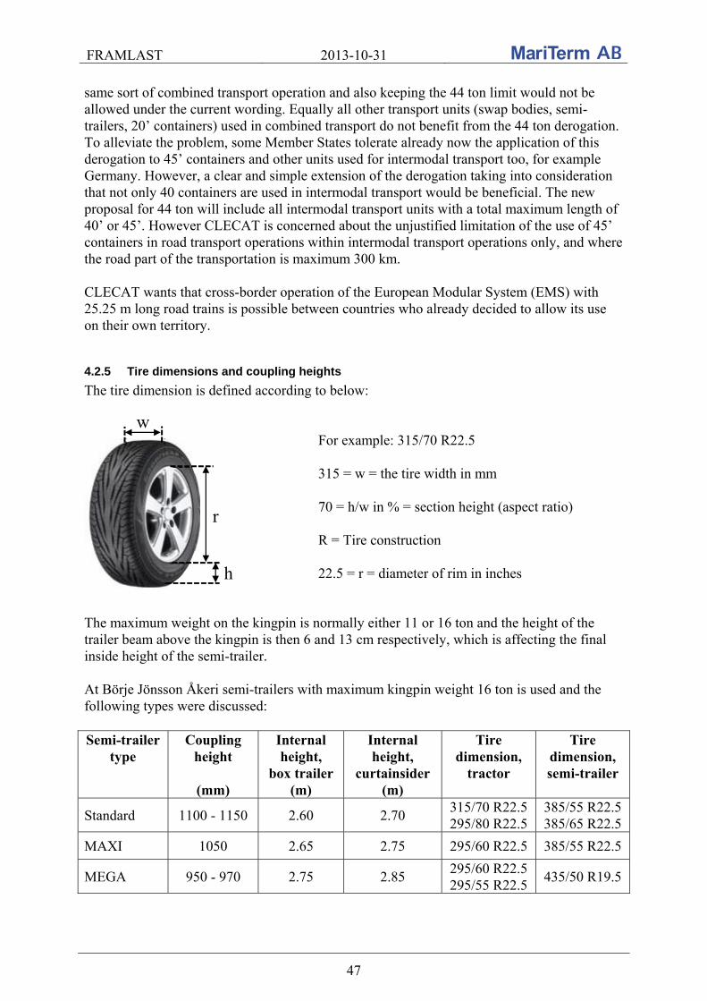
FRAMLAST 2013-10-31
47
same sort of combined transport operation and also keeping the 44 ton limit would not be allowed under the current wording. Equally all other transport units (swap bodies, semi-trailers, 20’ containers) used in combined transport do not benefit from the 44 ton derogation. To alleviate the problem, some Member States tolerate already now the application of this derogation to 45’ containers and other units used for intermodal transport too, for example Germany. However, a clear and simple extension of the derogation taking into consideration that not only 40 containers are used in intermodal transport would be beneficial. The new proposal for 44 ton will include all intermodal transport units with a total maximum length of 40’ or 45’. However CLECAT is concerned about the unjustified limitation of the use of 45’ containers in road transport operations within intermodal transport operations only, and where the road part of the transportation is maximum 300 km. CLECAT wants that cross-border operation of the European Modular System (EMS) with 25.25 m long road trains is possible between countries who already decided to allow its use on their own territory.
4.2.5 Tire dimensions and coupling heights
The tire dimension is defined according to below:
w
h
r
For example: 315/70 R22.5 315 = w = the tire width in mm 70 = h/w in % = section height (aspect ratio) R = Tire construction 22.5 = r = diameter of rim in inches
The maximum weight on the kingpin is normally either 11 or 16 ton and the height of the trailer beam above the kingpin is then 6 and 13 cm respectively, which is affecting the final inside height of the semi-trailer. At Börje Jönsson Åkeri semi-trailers with maximum kingpin weight 16 ton is used and the following types were discussed: Semi-trailer
type Coupling
height
(mm)
Internal height,
box trailer (m)
Internal height,
curtainsider (m)
Tire dimension,
tractor
Tire dimension, semi-trailer
Standard 1100 - 1150 2.60 2.70 315/70 R22.5 295/80 R22.5
385/55 R22.5 385/65 R22.5
MAXI 1050 2.65 2.75 295/60 R22.5 385/55 R22.5
MEGA 950 - 970 2.75 2.85 295/60 R22.5 295/55 R22.5
435/50 R19.5
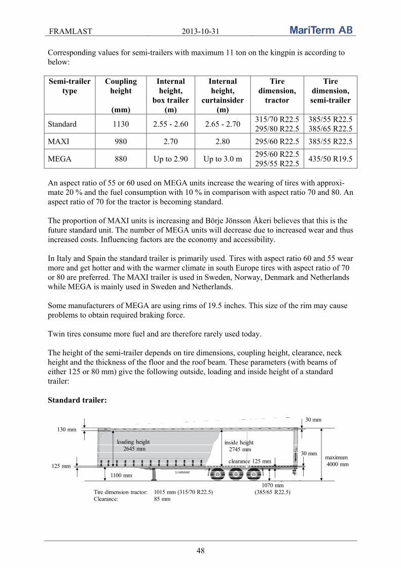
FRAMLAST 2013-10-31
48
Corresponding values for semi-trailers with maximum 11 ton on the kingpin is according to below: Semi-trailer
type Coupling
height
(mm)
Internal height,
box trailer (m)
Internal height,
curtainsider (m)
Tire dimension,
tractor
Tire dimension, semi-trailer
Standard 1130 2.55 - 2.60 2.65 - 2.70 315/70 R22.5 295/80 R22.5
385/55 R22.5 385/65 R22.5
MAXI 980 2.70 2.80 295/60 R22.5 385/55 R22.5
MEGA 880 Up to 2.90 Up to 3.0 m 295/60 R22.5 295/55 R22.5
435/50 R19.5
An aspect ratio of 55 or 60 used on MEGA units increase the wearing of tires with approxi-mate 20 % and the fuel consumption with 10 % in comparison with aspect ratio 70 and 80. An aspect ratio of 70 for the tractor is becoming standard. The proportion of MAXI units is increasing and Börje Jönsson Åkeri believes that this is the future standard unit. The number of MEGA units will decrease due to increased wear and thus increased costs. Influencing factors are the economy and accessibility. In Italy and Spain the standard trailer is primarily used. Tires with aspect ratio 60 and 55 wear more and get hotter and with the warmer climate in south Europe tires with aspect ratio of 70 or 80 are preferred. The MAXI trailer is used in Sweden, Norway, Denmark and Netherlands while MEGA is mainly used in Sweden and Netherlands. Some manufacturers of MEGA are using rims of 19.5 inches. This size of the rim may cause problems to obtain required braking force. Twin tires consume more fuel and are therefore rarely used today. The height of the semi-trailer depends on tire dimensions, coupling height, clearance, neck height and the thickness of the floor and the roof beam. These parameters (with beams of either 125 or 80 mm) give the following outside, loading and inside height of a standard trailer: Standard trailer:
maximum 4000 mm
130 mm
30 mm
125 mm
1100 mm
Tire dimension tractor: 1015 mm (315/70 R22.5)Clearance: 85 mm
loading height2645 mm
inside height2745 mm
1070 mm(385/65 R22.5)
clearance 125 mm30 mm
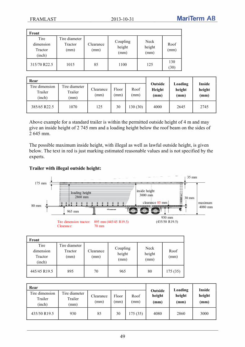
FRAMLAST 2013-10-31
49
Front Tire
dimension Tractor (inch)
Tire diameter Tractor (mm)
Clearance (mm)
Coupling height (mm)
Neck height (mm)
Roof (mm)
315/70 R22.5 1015 85 1100 125 130 (30)
Rear
Outside Height (mm)
Loading height (mm)
Inside height (mm)
Tire dimension Trailer (inch)
Tire diameter Trailer (mm)
Clearance (mm)
Floor (mm)
Roof (mm)
385/65 R22.5 1070 125 30 130 (30) 4000 2645 2745 Above example for a standard trailer is within the permitted outside height of 4 m and may give an inside height of 2 745 mm and a loading height below the roof beam on the sides of 2 645 mm. The possible maximum inside height, with illegal as well as lawful outside height, is given below. The text in red is just marking estimated reasonable values and is not specified by the experts. Trailer with illegal outside height:
175 mm
35 mm
80 mm
965 mm
930 mm(435/50 R19.5)
30 mm
Tire dimension tractor: 895 mm (445/45 R19.5)Clearance: 70 mm
maximum 4080 mm
loading height2860 mm
inside height3000 mm
clearance 85 mm
Front
Tire dimension
Tractor (inch)
Tire diameter Tractor (mm)
Clearance (mm)
Coupling height (mm)
Neck height (mm)
Roof (mm)
445/45 R19.5 895 70 965 80 175 (35) Rear
Outside height
(mm)
Loading height
(mm)
Inside height
(mm) Tire dimension
Trailer (inch)
Tire diameter Trailer (mm)
Clearance (mm)
Floor (mm)
Roof (mm)
435/50 R19.5 930 85 30 175 (35) 4080 2860 3000
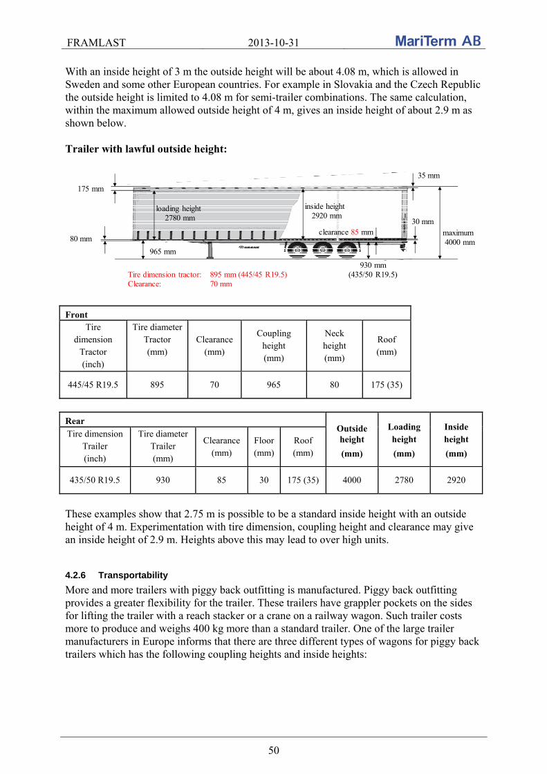
FRAMLAST 2013-10-31
50
With an inside height of 3 m the outside height will be about 4.08 m, which is allowed in Sweden and some other European countries. For example in Slovakia and the Czech Republic the outside height is limited to 4.08 m for semi-trailer combinations. The same calculation, within the maximum allowed outside height of 4 m, gives an inside height of about 2.9 m as shown below. Trailer with lawful outside height:
175 mm
35 mm
80 mm
965 mm
Tire dimension tractor: 895 mm (445/45 R19.5)Clearance: 70 mm
930 mm(435/50 R19.5)
30 mmmaximum 4000 mm
loading height2780 mm
inside height2920 mm
clearance 85 mm
Front
Tire dimension
Tractor (inch)
Tire diameter Tractor (mm)
Clearance (mm)
Coupling height (mm)
Neck height (mm)
Roof (mm)
445/45 R19.5 895 70 965 80 175 (35) Rear
Outside height
(mm)
Loading height
(mm)
Inside height
(mm) Tire dimension
Trailer (inch)
Tire diameter Trailer (mm)
Clearance (mm)
Floor (mm)
Roof (mm)
435/50 R19.5 930 85 30 175 (35) 4000 2780 2920 These examples show that 2.75 m is possible to be a standard inside height with an outside height of 4 m. Experimentation with tire dimension, coupling height and clearance may give an inside height of 2.9 m. Heights above this may lead to over high units.
4.2.6 Transportability
More and more trailers with piggy back outfitting is manufactured. Piggy back outfitting provides a greater flexibility for the trailer. These trailers have grappler pockets on the sides for lifting the trailer with a reach stacker or a crane on a railway wagon. Such trailer costs more to produce and weighs 400 kg more than a standard trailer. One of the large trailer manufacturers in Europe informs that there are three different types of wagons for piggy back trailers which has the following coupling heights and inside heights:

FRAMLAST 2013-10-31
51
Wagon type Coupling height
(mm) Internal height, curtainsider
(m)
Previous standard 1130 2.65 - 2.70
New standard 980 Up to 2.80
MEGA 880 Up to 3.0 m
The number of previous wagons is just a few. The new standard wagon is the most common used wagon.
Trailer with inside height up to 2.80 m loaded in a standard wagon
MEGA trailer loaded in a wagon
The inside height depends on the coupling height and the outside height on the codification profile on the railway track. In the north of Europe it is normally 4000 mm (P400) but in the south, especially through the Alps, it is 3850 mm (P385). The extra cost for trailers equipped with ferry outfitting is very small and provides a greater flexibility for the trailer. All trailers ordered to Scandinavia are provided with ferry outfitting. In terms of load distribution in a typical trailer design it is allowed to stow two ton per meter. There are no rules for maximum allowed deflection of a vehicle platform.
4.2.7 Cargo handling
In trailers the maximum free side opening is about 12 000 mm in box trailers and 13 000 mm in curtainsiders.

FRAMLAST 2013-10-31
52
Free side opening of a box trailer Free side opening of a curtainsider
Sliding roof is standard and 99 % of new trailers have sliding roof. The last percent is trailers for the UK and trailers with hamburger roof. Even if the roof never will be opened customers want the trailers to be flexible. The roof of XL-trailers has an optional diagonal spanning. The roof is possible to open approximate 11.3 m.
Sliding roof is needed for a second life Optional diagonal spanning for code XL
The distribution of produced trailers in Europe is approximate 90 % curtainsiders and 10 % box trailers. For swap bodies 10 % is curtainsiders and 90 % with box sides. Most of the box trailers are delivered to Scandinavia and in the US there are box trailers only. Box trailers are much more expensive to produce than curtainsiders. Side doors are no longer requested, except for some single customers. The number of box trailers, without side doors, is increasing and this because of the increasing risk of theft.
4.2.8 Cargo securing
Lashing bars are standard on new trailers. Normally the strength in each lashing hole is two ton and three holes per meter can simultaneously be used for 2 ton. A problem is to use horizontal lashings in the continuous lashing bars. Often the lashing bar is complemented with ordinary lashing points that can be used for loop lashings where one hook has to lay flat on the floor. A small percentage, approximate 10 %, of the trailer orders in Europe are equipped with fixed lashings and is often ordered in trailers for rent. The LC in fixed lashings is 2.5 tons.

FRAMLAST 2013-10-31
53
Stanchions are not standard but can be ordered as special equipment. The stanchions are normally 2 m long with dimension 70×70×4 or 80×80×4 and each stanchion weighs 8.5 - 12 kg. Approximate 10 % of the orders of trailers in Europe are equipped with stanchions. Each stanchion manages to withstand 400 kg on the top of the stanchion. During tests it is shown that the weak part is the base structure in the floor and not the stanchion.
4.2.9 Cargo care
The trend regarding anti-theft outfitting is getting more and more important. Krone informed that door locks are covered, the hinged safety lock under the rear door has padlock, electronic lock system via 2-way communication may be used etc.
Padlocks on the hinged safety lock under the rear doors.
Covered door locks
Electronic lock system via 2-way communication. According to Schmitz Cargobull the insurance companies in France require that curtainsiders are made with steel reinforcement not possible to cut up. Approximate 20 % of the total volume of curtainsiders from Schmitz has the antitheft outfitting.
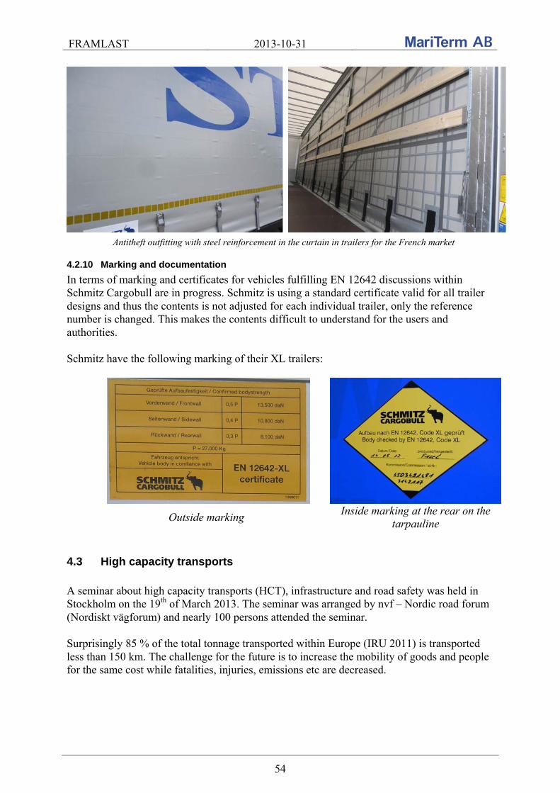
FRAMLAST 2013-10-31
54
Antitheft outfitting with steel reinforcement in the curtain in trailers for the French market
4.2.10 Marking and documentation
In terms of marking and certificates for vehicles fulfilling EN 12642 discussions within Schmitz Cargobull are in progress. Schmitz is using a standard certificate valid for all trailer designs and thus the contents is not adjusted for each individual trailer, only the reference number is changed. This makes the contents difficult to understand for the users and authorities.
Schmitz have the following marking of their XL trailers:
Outside marking Inside marking at the rear on the
tarpauline
4.3 High capacity transports
A seminar about high capacity transports (HCT), infrastructure and road safety was held in Stockholm on the 19th of March 2013. The seminar was arranged by nvf – Nordic road forum (Nordiskt vägforum) and nearly 100 persons attended the seminar. Surprisingly 85 % of the total tonnage transported within Europe (IRU 2011) is transported less than 150 km. The challenge for the future is to increase the mobility of goods and people for the same cost while fatalities, injuries, emissions etc are decreased.

FRAMLAST 2013-10-31
55
Road transport tonnage distances in modern economics
The reduced wear of the road per ton of goods transported in the modular system of length
25.25 is estimated to 30 % by using two modular trucks instead of three trucks, see sketches below.
Reduced wear of road of the three upper trucks approved in EU and the two modular vehicles approved in Sweden, Finland, the Netherlands,
Norway and Denmark
Comparison between 25.25 m vehicles and 18.75 / 16.5 m vehicles
The European directive 96/53/EG, article 4, paragraph 4 and 5, is regulating the length, width, height and weight of the vehicles within EU but each country may permit national transports
that are longer, higher, wider and heavier that do not significantly affect international competition. In Sweden heavy transports may be approved by exemption from the Swedish Transport Administration (Trafikverket) or by a regulation by the Swedish Transport Agency (Transportstyrelsen). Long or long and heavy transports may only be approved by a regulation by the Swedish Transport Agency. Exemption for “dividable loads” may be given at major transportation needs where other solutions are missing (rail) and where from an economic perspective it is currently not reasonable for a "normal transport", taking into account the amount of transport needed. Ongoing projects with long and/or heavy transports in Sweden are among others:
Timber between Överkalix and Piteå, 90 ton, 30 m, 11 axles, 4 piles (ETT) Two semi-trailers between Malmö and Gothenburg, 80 ton, 32.5 m, 11 axles (DUO2)
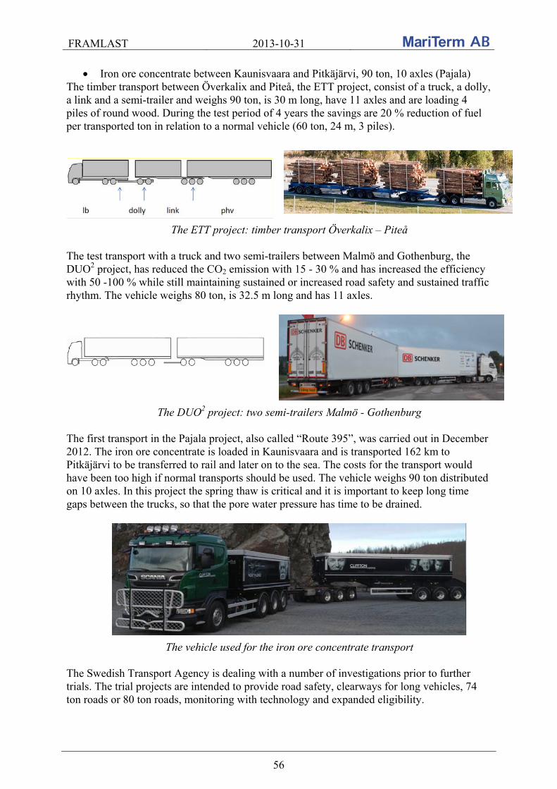
FRAMLAST 2013-10-31
56
Iron ore concentrate between Kaunisvaara and Pitkäjärvi, 90 ton, 10 axles (Pajala) The timber transport between Överkalix and Piteå, the ETT project, consist of a truck, a dolly, a link and a semi-trailer and weighs 90 ton, is 30 m long, have 11 axles and are loading 4 piles of round wood. During the test period of 4 years the savings are 20 % reduction of fuel per transported ton in relation to a normal vehicle (60 ton, 24 m, 3 piles).
The ETT project: timber transport Överkalix – Piteå The test transport with a truck and two semi-trailers between Malmö and Gothenburg, the DUO2 project, has reduced the CO2 emission with 15 - 30 % and has increased the efficiency with 50 -100 % while still maintaining sustained or increased road safety and sustained traffic rhythm. The vehicle weighs 80 ton, is 32.5 m long and has 11 axles.
The DUO2 project: two semi-trailers Malmö - Gothenburg The first transport in the Pajala project, also called “Route 395”, was carried out in December 2012. The iron ore concentrate is loaded in Kaunisvaara and is transported 162 km to Pitkäjärvi to be transferred to rail and later on to the sea. The costs for the transport would have been too high if normal transports should be used. The vehicle weighs 90 ton distributed on 10 axles. In this project the spring thaw is critical and it is important to keep long time gaps between the trucks, so that the pore water pressure has time to be drained.
The vehicle used for the iron ore concentrate transport The Swedish Transport Agency is dealing with a number of investigations prior to further trials. The trial projects are intended to provide road safety, clearways for long vehicles, 74 ton roads or 80 ton roads, monitoring with technology and expanded eligibility.
FRAMLAST 2013-10-31
57
It was concluded that the high capacity transports have ability to contribute to the climate targets. The opportunities for high capacity transports are:
A great part of the road network can be utilized more More efficient use of the road network Reduced need for new investments in roads and bridges
The constraints for high capacity transports are:
Regulations do not allow this type of vehicle The acceptance of this type of transport among policy makers and the public The relation to other modes of transport Development and production of vehicles Accessibility on the road network (bridges, geometry, buoyancy, sustainability, road
design, various road maintenance etc) Other infrastructure Diversion road network
Kari Saari from Ministry of Transport and Communications in Finland informed about the Finnish proposal to permanent increase masses according to below:
Truck with 4 axles from 32 ton to 35 ton Truck with 5 axles from 38 ton to 42 ton Truck and trailer combination with 8 axles from 60 ton to 64*) Truck and trailer combination with 9 axles from 60 ton to 69 ton**) Truck’s bogie with 3 axles from 24 ton to 27 ton***)
*) If 65 % of total mass of the trailer(s) is directed to axles fitted with twin tires to 68 ton **) If 65 % of total mass of the trailer(s) is directed to axles fitted with twin tires to 76 ton ***) On the condition that minimum 2 axles are fitted with twin tires
and to temporary, for a five year period, increase:
Truck with 2 axles from 18 ton to 20 ton Truck with 3 axles from 26 ton to 28 ton Truck and trailer combination with 7 axles from 60 ton to 64 ton
The allowed vehicle height is proposed to be increased from 4.2 m to 4.4 m. See the result of the Finnish proposals in section 7.2.
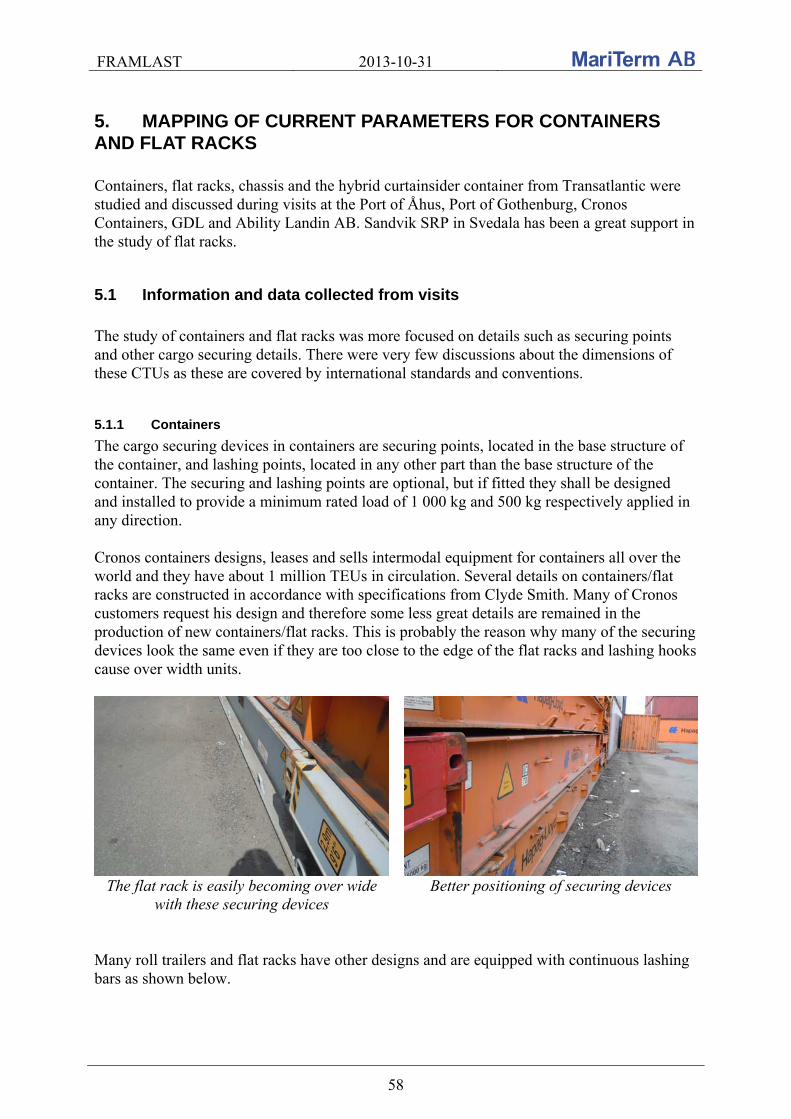
FRAMLAST 2013-10-31
58
5. MAPPING OF CURRENT PARAMETERS FOR CONTAINERS AND FLAT RACKS Containers, flat racks, chassis and the hybrid curtainsider container from Transatlantic were studied and discussed during visits at the Port of Åhus, Port of Gothenburg, Cronos Containers, GDL and Ability Landin AB. Sandvik SRP in Svedala has been a great support in the study of flat racks.
5.1 Information and data collected from visits
The study of containers and flat racks was more focused on details such as securing points and other cargo securing details. There were very few discussions about the dimensions of these CTUs as these are covered by international standards and conventions.
5.1.1 Containers
The cargo securing devices in containers are securing points, located in the base structure of the container, and lashing points, located in any other part than the base structure of the container. The securing and lashing points are optional, but if fitted they shall be designed and installed to provide a minimum rated load of 1 000 kg and 500 kg respectively applied in any direction. Cronos containers designs, leases and sells intermodal equipment for containers all over the world and they have about 1 million TEUs in circulation. Several details on containers/flat racks are constructed in accordance with specifications from Clyde Smith. Many of Cronos customers request his design and therefore some less great details are remained in the production of new containers/flat racks. This is probably the reason why many of the securing devices look the same even if they are too close to the edge of the flat racks and lashing hooks cause over width units.
The flat rack is easily becoming over wide with these securing devices
Better positioning of securing devices
Many roll trailers and flat racks have other designs and are equipped with continuous lashing bars as shown below.

FRAMLAST 2013-10-31
59
Continuous lashing bar on a roll trailer 45’ high cube pallet wide container In addition to the large fleet of standard 20’ and 40’ containers for over-sea transport, with inside width 2.33 m, the 45’ pallet wide containers, with inside width 2.44 m, is becoming more common on the European market. The 45’ PWHC containers can be handled, stacked and in general shipped more easily than semi-trailers. These pallet wide containers are adequate for shipping Euro-pallets and for example it is possible to ship 33 Euro-pallets in a 45’ pallet wide container in comparison to 25 and 27 in a 40’ respectively 45’ standard container. A semi-trailer has theoretically space for 34 Euro-pallets. Also the fleet of high cube containers (9’ 6”) is increasing. The inside height in these is 2695 mm instead of 2385 mm in a standard container. All new standard 40’ maritime containers are high cube containers. Typical dimensions of a high cube pallet wide 45’ container (PWHC) are according to below. PWHC:
External:
Internal:
Door:
Length: Width: Height:
Length: Width: Height: Volume:
Width: Height:
Payload: Tare:
13 715 mm 2 500 mm 2 896 mm
13 550 mm 2 430 mm 2 690 mm 89,1 m3
2 350 mm 2 580 mm
29 550 kg 4 450 kg
For information the Swedish regulation regarding containers, Containerlagen (1980:152), applies to containers used in international traffic only. International traffic refers to, unless otherwise specified in the law, transport operations to and from Sweden, or in transit through Sweden. There is no regulation for domestic container transport, which is a safety issue because the old equipment that does not meet the international requirements is used in the national market.
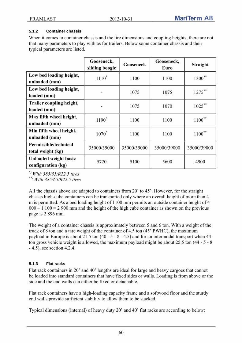
FRAMLAST 2013-10-31
60
5.1.2 Container chassis
When it comes to container chassis and the tire dimensions and coupling heights, there are not that many parameters to play with as for trailers. Below some container chassis and their typical parameters are listed.
Gooseneck, sliding boogie
Gooseneck Gooseneck,
Euro Straight
Low bed loading height, unloaded (mm)
1110* 1100 1100 1300**
Low bed loading height, loaded (mm)
- 1075 1075 1275**
Trailer coupling height, loaded (mm)
- 1075 1070 1025**
Max fifth wheel height, unloaded (mm)
1190* 1100 1100 1100**
Min fifth wheel height, unloaded (mm)
1070* 1100 1100 1100**
Permissible/technical total weight (kg)
35000/39000 35000/39000 35000/39000 35000/39000
Unloaded weight basic configuration (kg)
5720 5100 5600 4900
*) With 385/55/R22.5 tires **) With 385/65/R22.5 tires All the chassis above are adapted to containers from 20’ to 45’. However, for the straight chassis high-cube containers can be transported only where an overall height of more than 4 m is permitted. As a bed loading height of 1100 mm permits an outside container height of 4 000 – 1 100 = 2 900 mm and the height of the high cube container as shown on the previous page is 2 896 mm. The weight of a container chassis is approximately between 5 and 6 ton. With a weight of the truck of 8 ton and a tare weight of the container of 4.5 ton (45’ PWHC), the maximum payload in Europe is about 21.5 ton (40 - 5 - 8 - 4.5) and for an intermodal transport when 44 ton gross vehicle weight is allowed, the maximum payload might be about 25.5 ton (44 - 5 - 8 - 4.5), see section 4.2.4.
5.1.3 Flat racks
Flat rack containers in 20’ and 40’ lengths are ideal for large and heavy cargoes that cannot be loaded into standard containers that have fixed sides or walls. Loading is from above or the side and the end walls can either be fixed or detachable. Flat rack containers have a high-loading capacity frame and a softwood floor and the sturdy end walls provide sufficient stability to allow them to be stacked. Typical dimensions (internal) of heavy duty 20’ and 40’ flat racks are according to below:

FRAMLAST 2013-10-31
61
Length
(m) Width
(m) Height
(m) Tare weight
(kg) Payload
(kg)
20’ 5.96 2.40 2.29 3 000 Up to 37 000
40’ 11.65 2.37 1.96 5 250 Up to 44 650
Special focus has been given the lashing points on flat racks. The dimension, number, strength and location vary between the different manufacturers and one flat rack is not the other like. According to the ISO standard for flat racks, ISO 1496-5, the cargo securing devices on platforms and platform-based containers are securing points, located in the base structure of the container, and lashing points, located in any other part of the container other than the base structure. The securing and lashing points shall be designed and installed to provide a minimum rated load of 3 000 kg and 1000 kg respectively applied in any direction.
5.1.4 Swap bodies
At the fair trade Transport Logistic in Munich in June 2013 DB Schenker and Krone showed a 45’ swap-body with almost 3 m inside height within the 4 m total height. The loading volume is approximately 100 m3, the free inside height 2 980 mm, the payload 24.5 ton and the tare weight 6.5 ton.
Free inside height 2980 mm, required coupling height 830 mm, outside height 4000 mm, payload 24.5 ton and tare weight 6.5 ton.
5.1.5 Curtain side containers
The Port of Åhus was visited and together with Ability Landin AB and TransAtlantic the CUSI unit – curtain side container – was inspected and discussed.

FRAMLAST 2013-10-31
62
Ability Landin is a consultancy within the transport and logistics sector. The company provides transportation solutions primarily between Sweden and the British Isles. Among others they offer container-based shipping line served by container ships in cooperation with TransAtlantic. The TransAtlantic curtain side container was first used in the summer of 2006 and 100 units were in operation. Today there are just 80 units left and cruising in Europe only. The units have two opening curtain sides and doors on one end. The dimensions are according to below: CUSI:
External: Internal:
Length: Width: Height: Length: Width: Height: Height, sideloading: Volume: Payload: Tare:
13 600 mm 2 500 mm 2 900 mm 13 450 mm 2 430/2 470 mm 2 580 mm 2 520 mm 85 m3
29 030 kg 4 970 kg
Many of the customers of Ability Landin and TransAtlantic are asking for 45’ stackable container units (≈ 13.6 m). The CUSI is limiting the cargo height with the internal height 2 580 mm. The floor height of the curtain side containers is about 275 mm compared with 170 mm in a standard container. Since they have the same external dimensions about 100 mm is lost in height. This can cause problems for certain types of goods. The CUSI unit has a free inner width of 2 430 mm to be compared with the trailer width of approximate 2480 mm. This difference is very important and 5 cm more in the CUSI’s would give better flexibility for different types of goods. There may be problems in the CUSI with two pallets of for example cartons or shrink filmed cargo in width. The CUSI weighs approximately 700 kg more than the PWHC container shown above. Both sides on the CUSI unit are possible to open. The repair cost and the torsional stiffness would of course be lower respective better with one fixed side. One fixed side on new units would decrease the repair cost and increase the torsional stiffness. It has been discussed whether two fixed ends would be an alternative to doors in one end, but no; a fixed end does not weigh less or be more torsional stiff than an end with two doors. Further, it is much more work to open the sides than the rear end.
FRAMLAST 2013-10-31
63
The roof of the CUSI unit is of thin glass fiber to keep the tare weight down. The unit would have had sliding roof if it had been possible. The sides in the CUSI unit are of curtainsider type to keep the weight down. The CUSI units are not stable enough to lift with a fork lift. The handling of the units is done by top lifting. The CUSI units are not equipped with pockets for grappler arms. The loaded CUSI units may be stacked two high only. The CUSI units are equipped with corner fittings for locking of units to the ship’s deck or to other units. No external lashing points are thus needed. The sides in the CUSI unit are not used for cargo securing. The cargo inside the units is lashed. To summarize the experiences of practical use of the CUSI units the advantages and disadvantages are compiled below: Advantages with the CUSI unit:
The flexibility with loading also from the side copared to a container The units are circulating in normal container traffic Stackable Increase the market for Transatlantic and their container traffic to UK
Disadvantages with the CUSI unit:
High repair cost due to damages to the sides during loading and unloading on board the ships
Poor torsional stiffness Lower loading height than for trailers and normal high cube containers Less loading length than for trailers Less payload than for other units The loading width between the stanchions is limited to 2430 mm Difficulty of closing the unit Fixed web lashings
The CUSI are units are more expensive, they will break more easily and they have less second hand market than a container.
FRAMLAST 2013-10-31
64
5.2 Information and results from the field studies and tests
A number of field studies and tests have been carried out within the project. A field study of containers was carried out in different container terminals in Slovakia, Czech Republic and Sweden. A pre-study of testing the strength in the corrugation and in the lashing points in containers was carried out in Gothenburg with a container from Cronos. Additional tests were performed within the research activities of the Department of Road and Urban Transport, University of Zilina, Slovakia. The tests in Slovakia were carried out in a 40’ general purpose maritime container from Hapag-Lloyd.
5.2.1 Field study of 20’ and 40’ general purpose containers
Several terminal operators have made it possible to make a field study of 20’ and 40’ general purpose containers by allowing inspections of empty containers in their empty storage yards.
5.2.1.1 Introduction
General purpose maritime containers present the majority of maritime containers used in the world. This section presents the results of field-study analysis performed in different container terminals in Slovakia, Czech Republic and Sweden. Several terminal operators have made it possible to make such analysis by allowing inspections of empty containers in their empty storage yards. From the point of load securing maritime container is a structure with strong walls and other cargo securing systems, mainly lashing rings and lashing bars. The requirements for cargo securing systems (where provided) are specified in Annex F to the standard ISO 1496-1. In line with F.1.2 these systems consist of:
- shoring, or - cargo securing devices, or - combination of both.
The Annex F describes cargo securing devices only. “They are permanent fixtures to which lashings (such as ropes, straps, chains, cables, etc.) may be attached.” These cargo securing devices are optional for freight containers. If they are fitted then Annex F of the standard must be followed. However, the section F.2.2 defines “the typical number” but it is not defined that containers shall have a minimum number of anchoring and lashing points. According to section F.1.3.1 of the standard: “Anchoring points are securing devices located in the base structure of the container” and “Lashing points are securing devices located in any part of the container other than their base structure.” The difference between lashing points and anchoring points is not only in fitting place but also in required minimum strength of 1000 daN for anchoring points and 500 daN for lashing points - applied in any direction. This statement is not in line with the testing requirement F.3.1 where such points are tested: “in a plane perpendicular to the axis of the container structural member to which it is attached and at an angle of 45° to the horizontal plane.“ Annex F2.2 of the standard defines typical number of anchoring and lashing points as follows:
- anchoring points for 40’ containers 1AAA, 1AA, 1A, 1AX – total 16 anchoring points for 20’containers 1CC, 1C, 1CX – total 10 anchoring points
- lashing points – the number is not specified
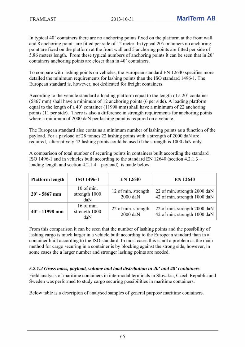
FRAMLAST 2013-10-31
65
In typical 40’ containers there are no anchoring points fixed on the platform at the front wall and 8 anchoring points are fitted per side of 12 meter. In typical 20’containers no anchoring point are fixed on the platform at the front wall and 5 anchoring points are fitted per side of 5.86 meters length. From these typical numbers of anchoring points it can be seen that in 20’ containers anchoring points are closer than in 40’ containers. To compare with lashing points on vehicles, the European standard EN 12640 specifies more detailed the minimum requirements for lashing points than the ISO standard 1496-1. The European standard is, however, not dedicated for freight containers. According to the vehicle standard a loading platform equal to the length of a 20’ container (5867 mm) shall have a minimum of 12 anchoring points (6 per side). A loading platform equal to the length of a 40’ container (11998 mm) shall have a minimum of 22 anchoring points (11 per side). There is also a difference in strength requirements for anchoring points where a minimum of 2000 daN per lashing point is required on a vehicle. The European standard also contains a minimum number of lashing points as a function of the payload. For a payload of 28 tonnes 22 lashing points with a strength of 2000 daN are required, alternatively 42 lashing points could be used if the strength is 1000 daN only.
A comparison of total number of securing points in containers built according the standard ISO 1496-1 and in vehicles built according to the standard EN 12640 (section 4.2.1.3 – loading length and section 4.2.1.4 – payload) is made below.
Platform length ISO 1496-1 EN 12640 EN 12640
20’ - 5867 mm 10 of min.
strength 1000 daN
12 of min. strength 2000 daN
22 of min. strength 2000 daN 42 of min. strength 1000 daN
40’ - 11998 mm 16 of min.
strength 1000 daN
22 of min. strength 2000 daN
22 of min. strength 2000 daN 42 of min. strength 1000 daN
From this comparison it can be seen that the number of lashing points and the possibility of lashing cargo is much larger in a vehicle built according to the European standard than in a container built according to the ISO standard. In most cases this is not a problem as the main method for cargo securing in a container is by blocking against the strong side, however, in some cases the a larger number and stronger lashing points are needed.
5.2.1.2 Gross mass, payload, volume and load distribution in 20’ and 40’ containers
Field analysis of maritime containers in intermodal terminals in Slovakia, Czech Republic and Sweden was performed to study cargo securing possibilities in maritime containers. Below table is a descripion of analysed samples of general purpose maritime containers.

FRAMLAST 2013-10-31
66
20‘ 40‘
Total ISO 1 code 1CC 1CCC 1AA 1AAA
Container size and type
code1) 22G0 22G1 25G1 42G0 42G1 45G0 45G1
No. of containers
2 154 1 1 102 1 125 386
1)G0 - no vents, G1 – passive vents in upper part of cargo space The samples that were analysed consist of 157 different models of 20’ containers (22G0, 22G1, 25G1), 103 different models of 40’ containers (42G0, 42G1) and 126 different models of 40’ high-cube containers (45G0, 45G1). According to the ISO standard 668 the gross mass (GM) of 20’ containers is 30 480 kg as well as for 40’ containers. The GM 32 500 kg, which is outside the standard, is nowadays frequently used for 40’ containers and in some cases also for 20’ containers. The table below describes analysed samples of general purpose containers in terms of GM.
20‘ general purpose
containers 40‘ general purpose
containers
Total ISO 1 code 1CC 1CCC 1AA 1AAA
Container size and type
code1) 22G0 22G1 25G1 42G0 42G1 45G0 45G1
Gro
ss
mas
s
24000 15 15 27000 1 1 30480 2 135 1 1 63 1 75 278 32500 3 39 50 92
Total 2 154 1 1 102 1 125 386
1) G0 - no vents, G1 – passive vents in upper part of cargo space In the diagram below the number of 20’ containers of type 22G1, 22G0 and 25G1 with different GM is plotted as function of the tare.
GM 24000 kg
GM 27000 kg
GM 30480 kg
GM 32500 kg
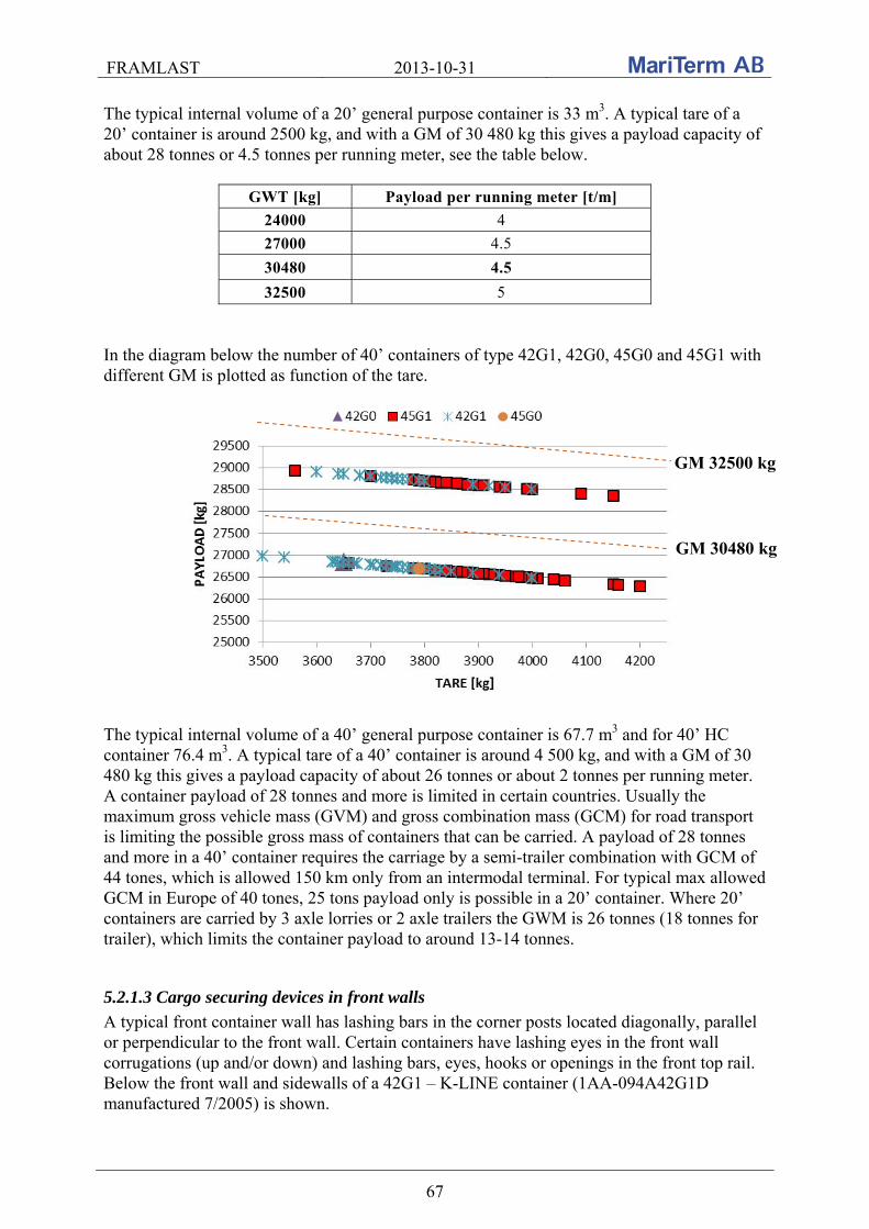
FRAMLAST 2013-10-31
67
The typical internal volume of a 20’ general purpose container is 33 m3. A typical tare of a 20’ container is around 2500 kg, and with a GM of 30 480 kg this gives a payload capacity of about 28 tonnes or 4.5 tonnes per running meter, see the table below.
GWT [kg] Payload per running meter [t/m]
24000 4
27000 4.5
30480 4.5
32500 5
In the diagram below the number of 40’ containers of type 42G1, 42G0, 45G0 and 45G1 with different GM is plotted as function of the tare.
The typical internal volume of a 40’ general purpose container is 67.7 m3 and for 40’ HC container 76.4 m3. A typical tare of a 40’ container is around 4 500 kg, and with a GM of 30 480 kg this gives a payload capacity of about 26 tonnes or about 2 tonnes per running meter. A container payload of 28 tonnes and more is limited in certain countries. Usually the maximum gross vehicle mass (GVM) and gross combination mass (GCM) for road transport is limiting the possible gross mass of containers that can be carried. A payload of 28 tonnes and more in a 40’ container requires the carriage by a semi-trailer combination with GCM of 44 tones, which is allowed 150 km only from an intermodal terminal. For typical max allowed GCM in Europe of 40 tones, 25 tons payload only is possible in a 20’ container. Where 20’ containers are carried by 3 axle lorries or 2 axle trailers the GWM is 26 tonnes (18 tonnes for trailer), which limits the container payload to around 13-14 tonnes.
5.2.1.3 Cargo securing devices in front walls
A typical front container wall has lashing bars in the corner posts located diagonally, parallel or perpendicular to the front wall. Certain containers have lashing eyes in the front wall corrugations (up and/or down) and lashing bars, eyes, hooks or openings in the front top rail. Below the front wall and sidewalls of a 42G1 – K-LINE container (1AA-094A42G1D manufactured 7/2005) is shown.
GM 30480 kg
GM 32500 kg

FRAMLAST 2013-10-31
68
Key: R-right, L-left, U-up, D-down
A typical container has 6 lashing bars in the front corner posts. Majority of analysed samples (63.7%) has 6 lashing bars in the front corner posts (3 pairs). 98.9% of analysed containers have at least 4 lashing bars. Below the number of securing points in the front wall of the analysed 20’ and 40’ containers is shown. From the first line in the table it can be seen that in the majority of the containers; 167 of the 386 analysed containers there were 6 diagonal lashing bars in the front wall. Of the 167 containers, 57 were of type 22G1, 1 of type 25G1, 48 of type 42G1 and 61 of type 45G1.
20‘ general purpose containers
40‘ general purpose containers
ISO 1 code
1CC 1CCC 1AA 1AAA
Cor
ner
pos
ts
fron
t to
p r
ail
corn
er
cast
ings
fron
t to
p r
ail
fron
t w
all
corr
uga
tion
s
22G
0
22G
1
25G
1
42G
0
42G
1
45G
0
45G
1
Tot
al
6/ - - - 57 1 48 61 1674/ - - - 25 12 13 506/ - 3/ - 10 8 8 268/ - - - 6 5 5 1610/ - - - 1 3 9 134/ 2/ - - 6 1 4 1110/ 2/ - 2U 3 4 2 94/ - 3E - 1 4 1 2 86- - - 4U4D 4 2 1 76I - - - 4 1 2 76/ 2/ 3/ 2U2D 4 2 66/ 2E - - 5 54- 2/ - - 1 1 2 46/ - - 3U 3 1 44/ - - 4U4D 1 1 1 3
Front top rail corner castings
Front top rail
Lashing eyes in side wall
corrugations 13UL+13UR+13D
L+13DR = 52
Lashing eyes in front wall corrugations
4U+4D
Lashing bars in corner posts located parallel to the front wall
3L+3R

FRAMLAST 2013-10-31
69
20‘ general purpose containers
40‘ general purpose containers
ISO 1 code
1CC 1CCC 1AA 1AAA
Cor
ner
pos
ts
fron
t to
p r
ail
corn
er
cast
ings
fron
t to
p r
ail
fron
t w
all
corr
uga
tion
s
22G
0
22G
1
25G
1
42G
0
42G
1
45G
0
45G
1
Tot
al
10/2E - - - 3 36/ 2E 1E - 2 1 36/ 2/ 3E 2U2D 3 36/ - 3/ 2 1 3-- - - - 1 1 26/ 2/ 1/ - 2 22/ - 3H - 1 1 26- - - - 1 1 2-- - - 2U2D 2 24- 2E 1E - 1 1 28/ - - 3U3D 1 1 26- 2E 1E - 1 1 24/ - - 3U3D 1 1 26I 2/ - - 1 18- - - - 1 16/ - - 3U3D 1 16/ - 4O - 1 18/ - - 4U 1 18/ - 3E 3D 1 16/ 2/ - - 1 16/ - - 2U2D 1 1
10I - 3/ - 1 14/ - 2E - 1 14/ 2E 1E - 1 18/ 2/ - - 1 14- - - 4U4D 1 14/ 2E - - 1 18/ 2/ - 2U 1 16/ 2E 3/ - 1 16- 2/ - - 1 16/ - 1/ - 1 110/ 2/ 2E - 1 16/ - - 2U 1 1
Total no. of containers 2 154 1 1 102 1 125 386
Key:
/...lashing bar diagonal to the corner of corner post, front top rail casting or front top rail -...lashing bar in corner post parallel to the front wall I...lashing bar in corner post perpendicular to the front wall H...hook
E...lashing eye U...lashing eye in front wall corrugation UP D... lashing eye in front wall corrugation DOWN O…hole
5.2.1.4 Cargo securing devices in side wall corrugations
According to section F.2.1 of the ISO standard 1496-1 “securing devices shall not infringe on the prescribed minimum internal dimensions”. Therefore the securing points are located inside side wall corrugations at the floor and roof level. Very rare securing points are located in between the corrugations. Below the number of anchoring points at the floor level at the side wall of the analysed 20’ and 40’ containers is shown.

FRAMLAST 2013-10-31
70
No. of
anchoring points
20‘ containers 40‘ containers
22G0 22G1 25G1 42G0 42G1 45G0 45G1 Total 20 51 1 73 12510 1 106 1 10816 5 17 19 4124 19 21 4012 22 228 17 1728 3 5 818 5 2 726 1 4 1 622 2 4 614 1 4 50 1 1
Total 2 154 1 1 102 1 125 386
From the table it can thus be seen that in typical 40’ container 20 anchoring points are fitted while in typical 20’ containers 10 anchoring points only are fitted.
The location of securing points depends on how many corrugations the container has. There are typical 20 corrugations in total in 20’ containers and 42 corrugations in 40’ containers. Below the total number of corrugations on both sides in the analysed 20’ and 40’ containers is shown.
Total number of internal
corrugations
20‘ containers 40‘ containers
22G0 22G1 25G1 42G0 42G1 45G0 45G1 Total
42 1 96 1 121 219 20 2 149 1 152 46 3 4 7
2FL35FL2 2 2 22 1 1
2FL21FL2 1 1 29 1 1
2FLXXFL2 1 1 61 1 1
2FL14FL2 1 1 Total 2 154 1 1 102 1 125 386
Certain 40’ containers of HANJIN have 46 corrugations and 20’ containers have 22 corrugations. Certain containers of OJSC TransContainer has 61 corrugations and some old containers has 2 flat surfaces (FL) at the front part and rear part of container side wall between corrugations (e.g. 2 corrugations, flat surface, 35 corrugations, flat surface, 2 corrugations). The typical location of securing points is in corrugation 1st, 5th, 9th, 14th, 19th, 24th, 29th, 34th, 38th and 42nd for 40’ containers and 1st, 5th, 10th, 15th, 20th for 20’ containers.
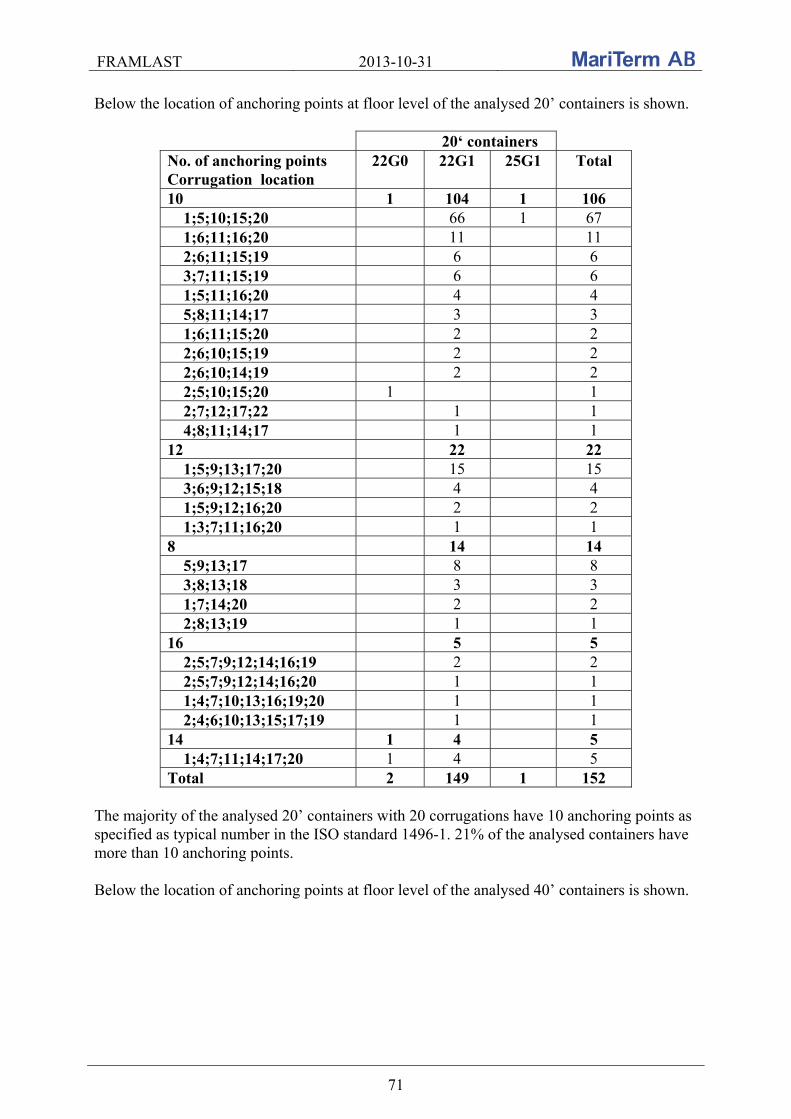
FRAMLAST 2013-10-31
71
Below the location of anchoring points at floor level of the analysed 20’ containers is shown.
20‘ containers No. of anchoring points Corrugation location
22G0 22G1 25G1 Total
10 1 104 1 106 1;5;10;15;20 66 1 67 1;6;11;16;20 11 11 2;6;11;15;19 6 6 3;7;11;15;19 6 6 1;5;11;16;20 4 4 5;8;11;14;17 3 3 1;6;11;15;20 2 2 2;6;10;15;19 2 2 2;6;10;14;19 2 2 2;5;10;15;20 1 1 2;7;12;17;22 1 1 4;8;11;14;17 1 1
12 22 22 1;5;9;13;17;20 15 15 3;6;9;12;15;18 4 4 1;5;9;12;16;20 2 2 1;3;7;11;16;20 1 1
8 14 14 5;9;13;17 8 8 3;8;13;18 3 3 1;7;14;20 2 2 2;8;13;19 1 1
16 5 5 2;5;7;9;12;14;16;19 2 2 2;5;7;9;12;14;16;20 1 1 1;4;7;10;13;16;19;20 1 1 2;4;6;10;13;15;17;19 1 1
14 1 4 5 1;4;7;11;14;17;20 1 4 5
Total 2 149 1 152
The majority of the analysed 20’ containers with 20 corrugations have 10 anchoring points as specified as typical number in the ISO standard 1496-1. 21% of the analysed containers have more than 10 anchoring points. Below the location of anchoring points at floor level of the analysed 40’ containers is shown.
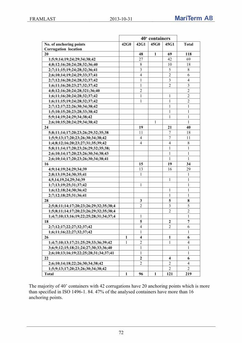
FRAMLAST 2013-10-31
72
40‘ containers
No. of anchoring points Corrugation location
42G0 42G1 45G0 45G1 Total
20 48 1 69 118 1;5;9;14;19;24;29;34;38;42 27 42 69 4;8;12;16;20;24;28;32;36;40 8 10 18 2;7;11;15;19;24;28;32;36;41 3 5 8 2;6;10;14;19;24;29;33;37;41 4 2 6 2;7;12;16;20;24;28;32;37;42 1 3 4 1;6;11;16;20;23;27;32;37;42 1 2 3 4;8;12;16;20;24;28;321;36;40 2 2 1;6;11;16;20;24;28;32;37;42 1 1 2 1;6;11;15;19;24;28;32;37;42 1 1 2 2;7;12;17;22;26;30;34;38;42 1 1 1;5;10;15;20;23;28;33;38;42 1 1 5;9;14;19;24;29;34;38;42 1 1 2;6;10;15;20;24;29;34;38;42 1 1
24 19 21 40 5;8;11;14;17;20;23;26;29;32;35;38 11 7 18 1;5;9;13;17;20;23;26;30;34;38;42 4 7 11 1;4;8;12;16;20;23;27;31;35;39;42 4 4 8 5;8;11;14;17;20;23;26;29;32;35;38; 1 1 2;6;10;14;17;20;23;26;30;34;38;43 1 1 2;6;10;14;17;20;23;26;30;34;38;41 1 1
16 15 19 34 4;9;14;19;24;29;34;39 13 16 29 2;8;13;19;24;30;35;41 1 1 4,9,14,19,24,29;34;39 1 1 1;7;13;19;25;31;37;42 1 1 1;6;12;18;24;30;36;42 1 1 2;7;12;18;25;31;36;41 1 1
28 3 5 8 2;5;8;11;14;17;20;23;26;29;32;35;38;4 2 3 5 1;5;8;11;14;17;20;23;26;29;32;35;38;4 2 2 1;4;7;10;13;16;19;22;25;28;31;34;37;4 1 1
18 5 2 7 2;7;12;17;22;27;32;37;42 4 2 6 1;6;11;16;22;27;32;37;42 1 1
26 1 4 1 6 1;4;7;10;13;17;21;25;29;33;36;39;42 1 2 1 4 3;6;9;12;15;18;21;24;27;30;33;36;40 1 1 2;6;10;13;16;19;22;25;28;31;34;37;41 1 1
22 2 4 6 2;6;10;14;18;22;26;30;34;38;42 2 2 4 1;5;9;13;17;20;23;26;30;34;38;42 2 2
Total 1 96 1 121 219
The majority of 40’ containers with 42 corrugations have 20 anchoring points which is more than specified in ISO 1496-1. 84. 47% of the analysed containers have more than 16 anchoring points.

FRAMLAST 2013-10-31
73
5.2.1.5 Cargo securing devices in the door end
The area at the doors usually consists of U-profiles with lashing bars at the sides, door rail and door rail castings on top where securing points can be located. According to section F.2.3 of the ISO standard 1496-1 “they shall not obstruct the door opening dimensions”. Below the number of securing points in the door end of the analysed 20’ and 40’ containers is shown.
No. of securing points
20‘ containers 40‘ containers
22G0 22G1 25G1 42G0 42G1 45G0 45G1 Total 6 84 1 56 69 210 4 2 36 1 17 1 21 78 8 29 26 19 74 10 2 2 16 20
No U- profile at doors
3
1
4
Total 2 154 1 1 102 1 125 386 The door U-profiles typically have 6 lashing bars at the front corner posts but also 4, 8 and 10 lashing bars occur frequently. 98.9% of the analysed containers have at least 4 lashing bars. The majority of the analysed containers (72%) have no lashing points on the door rail or door rail castings. Certain containers have lashing eyes or lashing bars on the door rail castings and lashing eyes, bars, holes or hooks on the door rail. Below the rear wall and side walls of a 22G1 – MAERSK container (MDDS-20SS-021B manufactured 3/2007) is shown.
The table below show the number of securing points on the door rail and the door rail castings in the analysed 20’ and 40’ containers.
Door rail – 3 lashing bars
U-profile 2x4 lashing bars
Lashing eyes in side wall corrugations 24 lashing eyes 1;5;9;13;17;20
Door rail corner castings – 2 lashing eyes
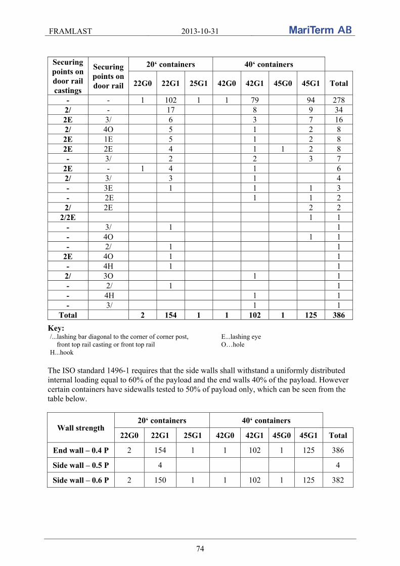
FRAMLAST 2013-10-31
74
Securing points on door rail castings
Securing points on door rail
20‘ containers 40‘ containers
22G0 22G1 25G1 42G0 42G1 45G0 45G1 Total
- - 1 102 1 1 79 94 278 2/ - 17 8 9 34 2E 3/ 6 3 7 16 2/ 4O 5 1 2 8 2E 1E 5 1 2 8 2E 2E 4 1 1 2 8 - 3/ 2 2 3 7
2E - 1 4 1 6 2/ 3/ 3 1 4 - 3E 1 1 1 3 - 2E 1 1 2 2/ 2E 2 2
2/2E 1 1 - 3/ 1 1 - 4O 1 1 - 2/ 1 1
2E 4O 1 1 - 4H 1 1 2/ 3O 1 1 - 2/ 1 1 - 4H 1 1 - 3/ 1 1
Total 2 154 1 1 102 1 125 386
Key: /...lashing bar diagonal to the corner of corner post, front top rail casting or front top rail H...hook
E...lashing eye O…hole
The ISO standard 1496-1 requires that the side walls shall withstand a uniformly distributed internal loading equal to 60% of the payload and the end walls 40% of the payload. However certain containers have sidewalls tested to 50% of payload only, which can be seen from the table below.
Wall strength 20‘ containers 40‘ containers
22G0 22G1 25G1 42G0 42G1 45G0 45G1 Total
End wall – 0.4 P 2 154 1 1 102 1 125 386
Side wall – 0.5 P 4 4
Side wall – 0.6 P 2 150 1 1 102 1 125 382

FRAMLAST 2013-10-31
75
5.2.2 Practical tests of strength of securing points in general purpose container
Tests of the strength of securing points in general purpose containers have been carried out in Gothenburg, Sweden as well as in Zilina, Slovakia.
5.2.2.1 Introduction
A prestudy of testing the strength of securing points in a general purpose container was carried out in Gothenburg on the 23rd of March 2012. The tests were carried out in a container from Cronos and the report from these tests is found in the Annex to this report. More detailed measurements of strength of container securing points were performed within the research activities of the Department of Road and Urban Transport, University of Zilina, Slovakia. The tests were carried out in a 40’ general purpose maritime container from Hapag-Lloyd (type 42G1). The test series was performed from 7th to 8th of November 2012. Weather during the tests was sunny or partly cloudy and the temperature was about 12°C. General purpose containers present the majority of maritime containers used globally. This section presents the results of measurements of carried out at the METRANS terminal in Dunajská Streda in Slovakia. From the point of load securing a maritime container is a structure with strong walls and other cargo securing systems, mainly lashing rings and lashing bars. The requirements for cargo securing systems (where provided) are specified in Annex F of the ISO standard 1496-1 and previously described in the section above. Annex F of the standard requires a minimum strength of 1000 daN for anchoring points and 500 daN for lashing points, with the force applied in any direction. This is in contradiction with the testing requirement in section F.3.1 according to which such points are tested - “in a plane perpendicular to the axis of the container structural member to which it is attached and at an angle of 45° to the horizontal plane“. The European standard EN 12640 for vehicles specifies more in detail that lashing points shall be tested in the most unfavourable directions; vertical lashing angle α = 30° to 90°, horizontal lashing angle longitudinal βx = 0° to 90°. Securing points in containers were tested in vertical lashing angles α = 0° to 90° and horizontal lashing angles longitudinal β = 0° to 90° in the tests carried out within the project.
5.2.2.2 Description of the containers and equipment used for the tests
Anchoring and lashing points were tested of a general purpose 40’ container from Hapag-Lloyd with the following parameters:
Serial number HLXU 4006136 Owner Hapag-Lloyd Manufactured type GH - 49413 Size and type code 42G1 Year of manufacture 1994 Internal length 12029 mm Internal width 2350 mm Internal height 2392 mm Maximum gross mass 30480 kg Tare 3780 kg

FRAMLAST 2013-10-31
76
Maximum payload 26700 kg Internal volume 67,7 m3 Lashing bars in front corner posts 2 x 3 (12mm / (20mm- right corner post repaired)) Lashing bars at doors 2 x 3 (12mm) Number of inner corrugations in sidewall 42 Lashing rings in sidewalls corrugations at floor level (total and positions in corrugations)
18 (12mm) 2;7;12;17;22;27;32;37;42
Lashing rings in sidewalls corrugations at roof level (total and positions in corrugations)
42 (12mm) 2;4;6;8;10;12;14;16;18;20;22; 24;26;28;30;32;34;36;38;40;42
A hydraulic piston with a hydraulic aggregate was used to create the force in the lashings. A load cell with a capacity up to 3200 daN and computer evaluation of the force was also used as well as lashing chains ( 8 mm) of LC 4000 daN, shackles and lashing hooks with webbing. The container and the test equipment are shown in the pictures below.

FRAMLAST 2013-10-31
77
The used lashing rings in each side wall corrugation was identified whether it is at floor level (D - down) or at roof level (U - up) as well as right side (R) and left side (L) of the container. Lashing bars in the front corner posts were identified numerically from the floor level and up as; 1RF (right front corner post), 2RF, 3RF, 1LF, 2LF and 3LF. Lashing bars at the doors were also defined numerically from the floor level and up as; 1RR (right door corner), 2RR, 3RR, 1LR, 2LR and3LR. 16 tests were carried out and the result is presented below.
5.2.2.3 TEST 1 – 22LU – 22RD lashing rings (12)
The first test was carried out between two securing points in the 22nd corrugation (at the centre of the container) from the container headboard identified as 22RD (right side down) and 22LU (left side up) which simulates the testing angle specified in the ISO standard 1496-1.
Test no.1 ( = 44°, x = 90°)
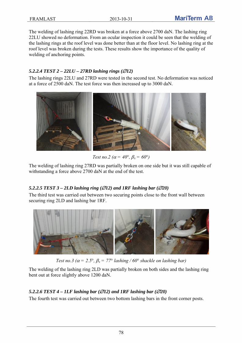
FRAMLAST 2013-10-31
78
The welding of lashing ring 22RD was broken at a force above 2700 daN. The lashing ring 22LU showed no deformation. From an ocular inspection it could be seen that the welding of the lashing rings at the roof level was done better than at the floor level. No lashing ring at the roof level was broken during the tests. These results show the importance of the quality of welding of anchoring points.
5.2.2.4 TEST 2 – 22LU – 27RD lashing rings (12)
The lashing rings 22LU and 27RD were tested in the second test. No deformation was noticed at a force of 2500 daN. The test force was then increased up to 3000 daN.
Test no.2 ( = 40°, x = 60°)
The welding of lashing ring 27RD was partially broken on one side but it was still capable of withstanding a force above 2700 daN at the end of the test.
5.2.2.5 TEST 3 – 2LD lashing ring (12) and 1RF lashing bar (20)
The third test was carried out between two securing points close to the front wall between securing ring 2LD and lashing bar 1RF.
Test no.3 ( = 2.5°, x = 77° lashing / 60° shackle on lashing bar)
The welding of the lashing ring 2LD was partially broken on both sides and the lashing ring bent out at force slightly above 1200 daN.
5.2.2.6 TEST 4 – 1LF lashing bar (12) and 1RF lashing bar (20)
The fourth test was carried out between two bottom lashing bars in the front corner posts.

FRAMLAST 2013-10-31
79
Test no.4 ( = 0°, x = 90° lashing / 60° shackle on lashing bar / 66° hook on lashing bar)
The test force was increased slightly above 3100 daN peak force without any permanent deformation of the lashing bars.
5.2.2.7 TEST 5 – 1LF lashing bar (12) and two lashing rings 7RD + 12RD (12)
The fifth test was carried out between the lashing bar 1LF and two lashing rings 7RD and 12 RD at the floor level. Because of previous experiences with poor welding of bottom lashing rings the lashing force was distributed to two lashing rings.
Test no.5 ( = 0°, x = 43° lashing)
The lashing bar was capable of taking up a force of 2200 daN without any permanent deformation. Then the force was increased and the lashing bar bent out and the welding partially broke at a force slightly above 2900 daN. The lashing rings 7RD and 12LD did not show any permanent deformation.
5.2.2.8 TEST 6 – 1RF lashing bar (20) and lashing ring 14RU (12)
The sixth test was carried out between the bottom lashing bar in the right front corner post 1RF and the lashing ring 14RU.

FRAMLAST 2013-10-31
80
Test no.6 ( = 30°, x = 0° lashing)
The lashing ring and the bar were capable of taking up a force slightly above 3000 daN without any permanent deformation. It must, however, be noted that part of the force is transferred to the side wall because of the contact of the lashing with the container side wall as can be seen on the right photo above. The result also shows that such type of lashing is very efficient and the lashing rings are capable of withstanding higher force than 1000 daN, which is the requirement according to the standard even at the roof level where 500 daN is required.
5.2.2.9 TEST 7 – 1RF lashing bar (20) and lashing ring 6RU (12)
The seventh test was carried out between the bottom lashing bar in the right front corner post 1RF and the lashing ring 6RU.
Test no.7 ( = 53°, x = 0° lashing) The lashing ring and the bar were capable of taking up a force slightly above 3000 daN without permanent deformation.
5.2.2.10 TEST 8 – 1RF lashing bar (20) and lashing ring 2LU (12)
Test eight was carried out between the bottom lashing bar in the right front corner post 1RF and the lashing ring in the left side wall corrugation at the roof level 2LU.

FRAMLAST 2013-10-31
81
Test no.8 ( = 43°, x = 75° lashing) The lashing ring 2LU was capable of taking up a force of 3000 daN without permanent deformation.
5.2.2.11 TEST 9 – 1RF lashing bar (20) and lashing ring 6LU (12)
The ninth test was carried out between the bottom lashing bar in the right front corner post 1RF and the lashing ring in the left side wall corrugation at the roof level 6LU.
Test no. 9 ( = 38°, x = 54° lashing) The lashing ring 6LU was capable of taking up a force of 3000 daN without permanent deformation.
5.2.2.12 TEST 10 – 1RF lashing bar (20) and lashing ring 12LU (12)
Test ten was carried out between the bottom lashing bar in the right front corner post 1RF and the lashing ring in the left side wall corrugation at the roof level 12LU.
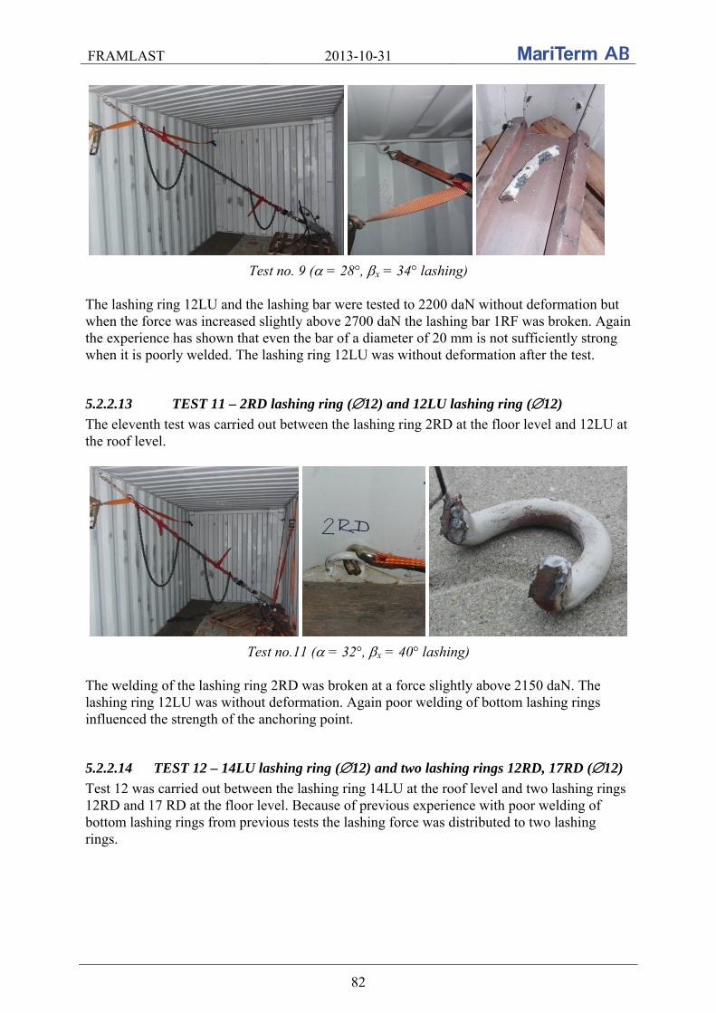
FRAMLAST 2013-10-31
82
Test no. 9 ( = 28°, x = 34° lashing) The lashing ring 12LU and the lashing bar were tested to 2200 daN without deformation but when the force was increased slightly above 2700 daN the lashing bar 1RF was broken. Again the experience has shown that even the bar of a diameter of 20 mm is not sufficiently strong when it is poorly welded. The lashing ring 12LU was without deformation after the test.
5.2.2.13 TEST 11 – 2RD lashing ring (12) and 12LU lashing ring (12)
The eleventh test was carried out between the lashing ring 2RD at the floor level and 12LU at the roof level.
Test no.11 ( = 32°, x = 40° lashing) The welding of the lashing ring 2RD was broken at a force slightly above 2150 daN. The lashing ring 12LU was without deformation. Again poor welding of bottom lashing rings influenced the strength of the anchoring point.
5.2.2.14 TEST 12 – 14LU lashing ring (12) and two lashing rings 12RD, 17RD (12)
Test 12 was carried out between the lashing ring 14LU at the roof level and two lashing rings 12RD and 17 RD at the floor level. Because of previous experience with poor welding of bottom lashing rings from previous tests the lashing force was distributed to two lashing rings.

FRAMLAST 2013-10-31
83
Test no.12 ( = 44°, x = 90° lashing) The lashing ring 14LU was capable of taking up a force of 3000 daN for 5 minutes without permanent deformation.
5.2.2.15 TEST 13 – 14RU lashing ring (12) and 14LU lashing ring (12)
The 13th test was carried out between the lashing ring 14RU and 14 LU at the roof level.
Test no.13 ( = 0°, x = 90° lashing) Both lashing rings bent out at a force of about 1300 daN, the maximum tension force was 2000 daN and stable force at the end of the test slightly above 1800 daN. Both the lashing rings were deformed but not broken. This test shows that such lashing angle is not suitable for such lashing rings when the force is higher than 1000 daN.
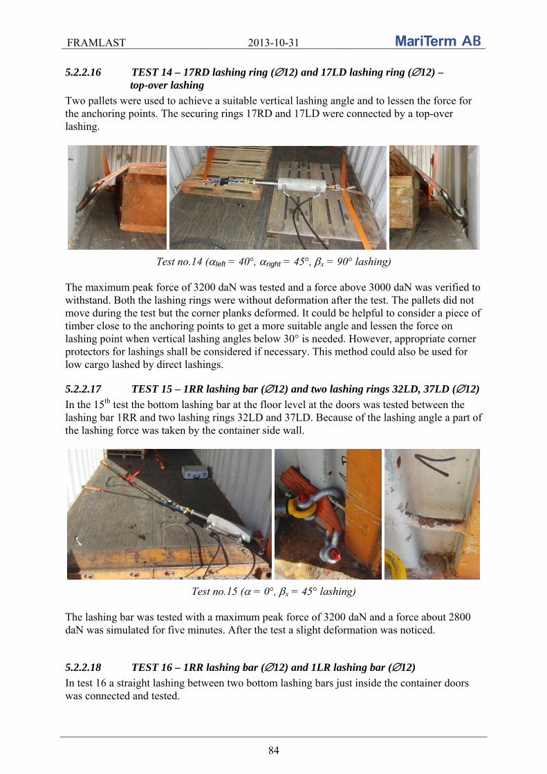
FRAMLAST 2013-10-31
84
5.2.2.16 TEST 14 – 17RD lashing ring (12) and 17LD lashing ring (12) – top-over lashing
Two pallets were used to achieve a suitable vertical lashing angle and to lessen the force for the anchoring points. The securing rings 17RD and 17LD were connected by a top-over lashing.
Test no.14 (left = 40°, right = 45°, x = 90° lashing) The maximum peak force of 3200 daN was tested and a force above 3000 daN was verified to withstand. Both the lashing rings were without deformation after the test. The pallets did not move during the test but the corner planks deformed. It could be helpful to consider a piece of timber close to the anchoring points to get a more suitable angle and lessen the force on lashing point when vertical lashing angles below 30° is needed. However, appropriate corner protectors for lashings shall be considered if necessary. This method could also be used for low cargo lashed by direct lashings.
5.2.2.17 TEST 15 – 1RR lashing bar (12) and two lashing rings 32LD, 37LD (12)
In the 15th test the bottom lashing bar at the floor level at the doors was tested between the lashing bar 1RR and two lashing rings 32LD and 37LD. Because of the lashing angle a part of the lashing force was taken by the container side wall.
Test no.15 ( = 0°, x = 45° lashing) The lashing bar was tested with a maximum peak force of 3200 daN and a force about 2800 daN was simulated for five minutes. After the test a slight deformation was noticed.
5.2.2.18 TEST 16 – 1RR lashing bar (12) and 1LR lashing bar (12)
In test 16 a straight lashing between two bottom lashing bars just inside the container doors was connected and tested.

FRAMLAST 2013-10-31
85
Test no.16 ( = 0°, x = 90° lashing) The lashing bars first withstood a maximum peak force of 2150 daN but when the tension force was increased again the lashing bar 1RR broke at the force slightly above 1800 daN. No deformation of the lashing bar 1LR was noticed. Again it can be concluded that the welding is different in different fittings and the welding quality should be improved in container manufacturing.
5.2.2.19 Summary
The results of the tests have shown that the quality of the welding strongly influence the strength of the lashing points and lashing bars. In the table below the result of the tests are collected.
Test no.
Las
hin
g ri
ng/
bar
- p
osit
ion
-
dia
met
er
Las
hin
g ri
ng/
bar
- p
osit
ion
-
dia
met
er
Ver
tica
l las
hin
g an
gle
- a
[°]
Hor
izon
tal l
ash
ing
angl
e to
lo
ngi
tud
inal
axi
s -
bx
[°]
Max
imu
m p
eak
for
ce [
daN
]
Max
imu
m f
orce
wh
en
def
orm
ed o
r d
etac
hed
[d
aN]
Max
imu
m r
ecom
men
ded
la
shin
g ca
pac
ity
[daN
]
Remarks
1 LR - 22LU -
Ø12 LR - 22RD -
Ø12 44 90 2708 2708 2150 22RD detached
2 LR - 22LU -
Ø12 LR - 27RD -
Ø12 40 60 3032 3013 2400
27RD welding partially broken
3 LR - 2LD -
Ø12 LB - 01RF -
Ø20 2,5 77 1265 1239 1000
2LD welding partially broken
4 LB - 1LF -
Ø12 LB - 1RF - Ø20 0 90 3188 - 2550 no deformation
5 LB - 1LF -
Ø12
LR - 7RD/12RD -
Ø12 0 43 2927 2927 2300 1LF deformed
6 LR - 14RU -
Ø12 LB - 1RF - Ø20 30 0 3180 - 2500 no deformation
7 LR - 6RU -
Ø12 LB - 1RF - Ø20 53 0 3230 - 2550 no deformation
8 LR - 2LU -
Ø12 LB - 1RF - Ø20 43 75 3172 - 2500 no deformation
9 LR - 6LU -
Ø12 LB - 1RF - Ø20 38 54 3204 - 2550 no deformation
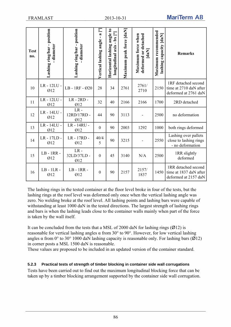
FRAMLAST 2013-10-31
86
Test no.
Las
hin
g ri
ng/
bar
- p
osit
ion
-
dia
met
er
Las
hin
g ri
ng/
bar
- p
osit
ion
-
dia
met
er
Ver
tica
l las
hin
g an
gle
- a
[°]
Hor
izon
tal l
ash
ing
angl
e to
lo
ngi
tud
inal
axi
s -
bx
[°]
Max
imu
m p
eak
for
ce [
daN
]
Max
imu
m f
orce
wh
en
def
orm
ed o
r d
etac
hed
[d
aN]
Max
imu
m r
ecom
men
ded
la
shin
g ca
pac
ity
[daN
]
Remarks
10 LR - 12LU -
Ø12 LB - 1RF - Ø20 28 34 2761
2761/ 2710
2150 1RF detached second time at 2710 daN after deformed at 2761 daN
11 LR - 12LU -
Ø12 LR - 2RD -
Ø12 32 40 2166 2166 1700 2RD detached
12 LR - 14LU -
Ø12
LR - 12RD/17RD -
Ø12 44 90 3113 - 2500 no deformation
13 LR - 14LU -
Ø12 LR - 14RU -
Ø12 0 90 2003 1292 1000 both rings deformed
14 LR - 17LD -
Ø12 LR - 17RD -
Ø12 40/4
5 90 3215 - 2550
Lashing over pallets close to lashing rings
- no deformation
15 LB - 1RR -
Ø12
LR - 32LD/37LD -
Ø12 0 45 3140 N/A 2500
1RR slightly deformed
16 LB - 1LR -
Ø12 LB - 1RR -
Ø12 0 90 2157
2157/ 1837
1450 1RR detached second time at 1837 daN after deformed at 2157 daN
The lashing rings in the tested container at the floor level broke in four of the tests, but the lashing rings at the roof level was deformed only once when the vertical lashing angle was zero. No welding broke at the roof level. All lashing points and lashing bars were capable of withstanding at least 1000 daN in the tested directions. The largest strength of lashing rings and bars is when the lashing leads close to the container walls mainly when part of the force is taken by the wall itself. It can be concluded from the tests that a MSL of 2000 daN for lashing rings (Ø12) is reasonable for vertical lashing angles α from 30° to 90°. However, for low vertical lashing angles α from 0° to 30° 1000 daN lashing capacity is reasonable only. For lashing bars (Ø12) in corner posts a MSL 1500 daN is reasonable. These values are proposed to be included in an updated version of the container standard.
5.2.3 Practical tests of strength of timber blocking in container side wall corrugations
Tests have been carried out to find out the maximum longitudinal blocking force that can be taken up by a timber blocking arrangement supported by the container side wall corrugation.

FRAMLAST 2013-10-31
87
5.2.3.1 Introduction
A prestudy of the strength in the container side wall corrugation was carried out in Gothenburg on the 23rd of March 2012. The report from this test is included in the Annex to this report. Measurements of strength of timber blocking in side wall corrugations of container were also performed within the research activities of the Department of Road and Urban Transport, University of Zilina, Slovakia. The tests were carried out in a 40’ general purpose maritime container from Hapag-Lloyd (type 42G1). The test series were carried out the 9th of November 2012. The weather during the tests was sunny and the temperature was about 22°C. In this section the results are presented of the measurements of the strength of the timber blocking in the side wall corrugations. The tests were carried out at the METRANS terminal in Dunajská Streda in Slovakia.
5.2.3.2 Description of the container and the equipment used for the tests
The timber blocking was tested in a 40’ container from Hapag-Lloyd. The container had side walls of a typical design with 42 inner corrugations inside the container. The parameters of the container used in tests are described in the section above for the tests of securing points and the dimensions of the corrugation is shown in the sketch below.
Dimensions of typical corrugation designs of 20’ and 40’ containers
A hydraulic piston with a hydraulic aggregate was used to create the testing force. A load cell with a capacity of up to 5000 daN and computer evaluation of the force was also used as well as lashing chains ( 8 mm) of MSL 4000 daN, square timber 100 100 mm (soft wood - spruce) and three types of blocking devices connected to the timber batten made of hardwood - hornbeam and polyamide (PA) Etralon 6 SA.
The container and equipment used in the tests are shown in the pictures below.
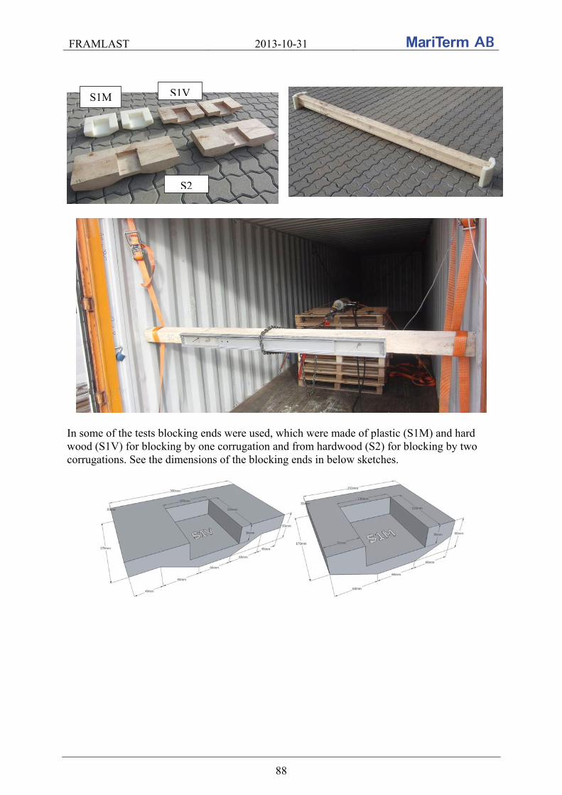
FRAMLAST 2013-10-31
88
In some of the tests blocking ends were used, which were made of plastic (S1M) and hard wood (S1V) for blocking by one corrugation and from hardwood (S2) for blocking by two corrugations. See the dimensions of the blocking ends in below sketches.
S1M S1V
S2
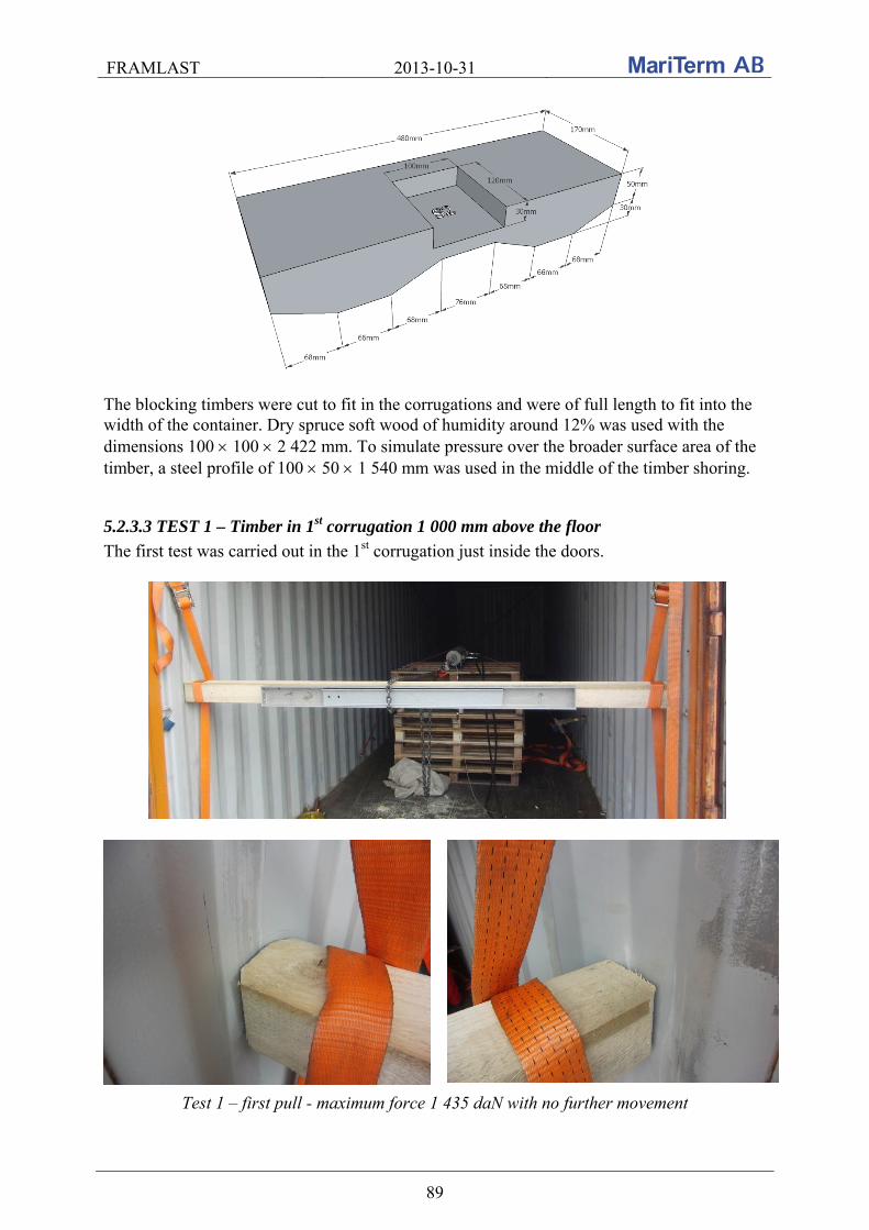
FRAMLAST 2013-10-31
89
The blocking timbers were cut to fit in the corrugations and were of full length to fit into the width of the container. Dry spruce soft wood of humidity around 12% was used with the dimensions 100 100 2 422 mm. To simulate pressure over the broader surface area of the timber, a steel profile of 100 50 1 540 mm was used in the middle of the timber shoring.
5.2.3.3 TEST 1 – Timber in 1st corrugation 1 000 mm above the floor
The first test was carried out in the 1st corrugation just inside the doors.
Test 1 – first pull - maximum force 1 435 daN with no further movement
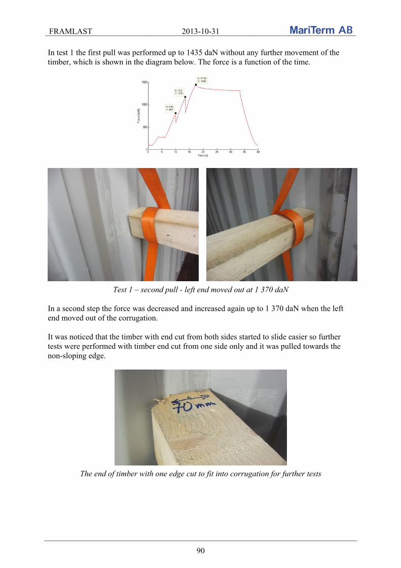
FRAMLAST 2013-10-31
90
In test 1 the first pull was performed up to 1435 daN without any further movement of the timber, which is shown in the diagram below. The force is a function of the time.
Test 1 – second pull - left end moved out at 1 370 daN In a second step the force was decreased and increased again up to 1 370 daN when the left end moved out of the corrugation. It was noticed that the timber with end cut from both sides started to slide easier so further tests were performed with timber end cut from one side only and it was pulled towards the non-sloping edge.
The end of timber with one edge cut to fit into corrugation for further tests
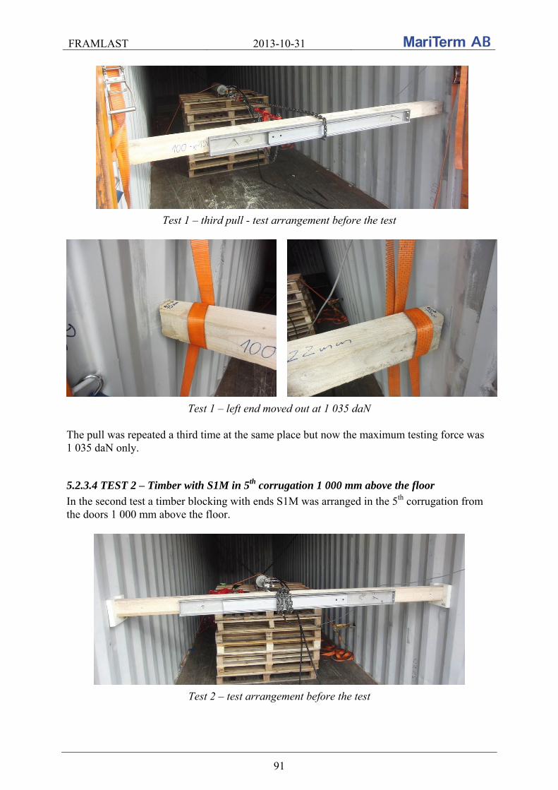
FRAMLAST 2013-10-31
91
Test 1 – third pull - test arrangement before the test
Test 1 – left end moved out at 1 035 daN The pull was repeated a third time at the same place but now the maximum testing force was 1 035 daN only.
5.2.3.4 TEST 2 – Timber with S1M in 5th corrugation 1 000 mm above the floor
In the second test a timber blocking with ends S1M was arranged in the 5th corrugation from the doors 1 000 mm above the floor.
Test 2 – test arrangement before the test
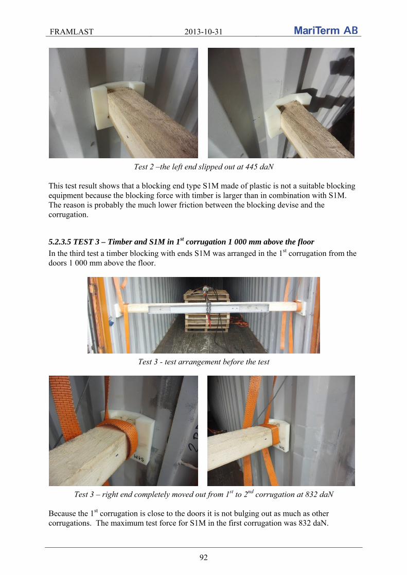
FRAMLAST 2013-10-31
92
Test 2 –the left end slipped out at 445 daN This test result shows that a blocking end type S1M made of plastic is not a suitable blocking equipment because the blocking force with timber is larger than in combination with S1M. The reason is probably the much lower friction between the blocking devise and the corrugation.
5.2.3.5 TEST 3 – Timber and S1M in 1st corrugation 1 000 mm above the floor
In the third test a timber blocking with ends S1M was arranged in the 1st corrugation from the doors 1 000 mm above the floor.
Test 3 - test arrangement before the test
Test 3 – right end completely moved out from 1st to 2nd corrugation at 832 daN Because the 1st corrugation is close to the doors it is not bulging out as much as other corrugations. The maximum test force for S1M in the first corrugation was 832 daN.
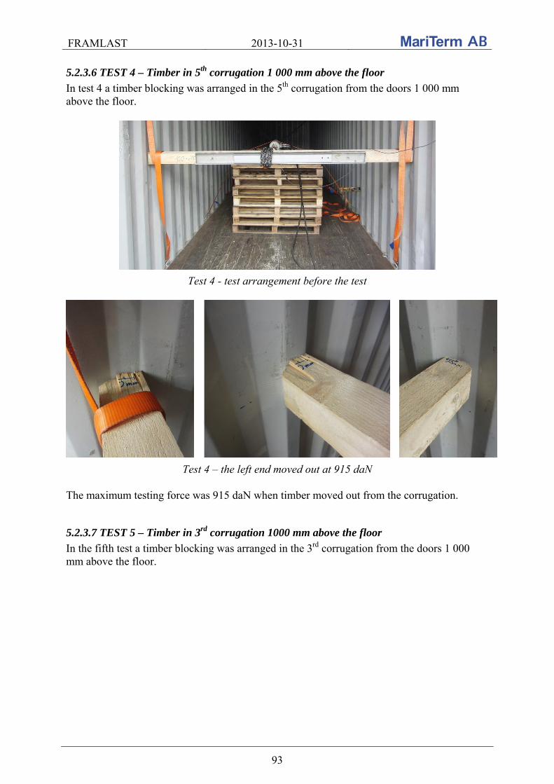
FRAMLAST 2013-10-31
93
5.2.3.6 TEST 4 – Timber in 5th corrugation 1 000 mm above the floor
In test 4 a timber blocking was arranged in the 5th corrugation from the doors 1 000 mm above the floor.
Test 4 - test arrangement before the test
Test 4 – the left end moved out at 915 daN The maximum testing force was 915 daN when timber moved out from the corrugation.
5.2.3.7 TEST 5 – Timber in 3rd corrugation 1000 mm above the floor
In the fifth test a timber blocking was arranged in the 3rd corrugation from the doors 1 000 mm above the floor.
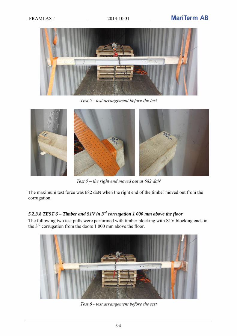
FRAMLAST 2013-10-31
94
Test 5 - test arrangement before the test
Test 5 – the right end moved out at 682 daN The maximum test force was 682 daN when the right end of the timber moved out from the corrugation.
5.2.3.8 TEST 6 – Timber and S1V in 3rd corrugation 1 000 mm above the floor
The following two test pulls were performed with timber blocking with S1V blocking ends in the 3rd corrugation from the doors 1 000 mm above the floor.
Test 6 - test arrangement before the test
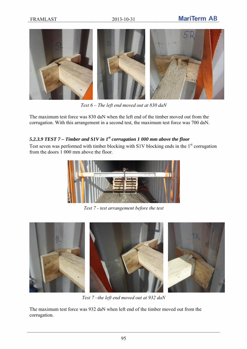
FRAMLAST 2013-10-31
95
Test 6 – The left end moved out at 830 daN The maximum test force was 830 daN when the left end of the timber moved out from the corrugation. With this arrangement in a second test, the maximum test force was 700 daN.
5.2.3.9 TEST 7 – Timber and S1V in 1st corrugation 1 000 mm above the floor
Test seven was performed with timber blocking with S1V blocking ends in the 1st corrugation from the doors 1 000 mm above the floor.
Test 7 - test arrangement before the test
Test 7 –the left end moved out at 932 daN The maximum test force was 932 daN when left end of the timber moved out from the corrugation.

FRAMLAST 2013-10-31
96
5.2.3.10 TEST 8 – Timber and S1M in 3rd corrugation 1 000 mm above the floor
The eighth test was performed with timber blocking with S1M blocking ends in the 3rd corrugation from the doors 1 000 mm above the floor.
Test 8 - the right end moved out at 467 daN The maximum test force was 467 daN when the right end of the timber moved out from the corrugation.
5.2.3.11 TEST 9 – Timber and S2 in 4th and 5th corrugation 1 000 mm above the floor
The ninth test was performed with timber blocking with S2 blocking ends in the 4th and 5th corrugation from the doors 1 000 mm above the floor.
Test 9 - test arrangement before the test
Test 9 – the left end moved out at 787 daN
The maximum test force was 787 daN when the left end of the timber moved out from the corrugation.

FRAMLAST 2013-10-31
97
5.2.3.12 TEST 10 – Timber and S2 in 1st and 2nd corrugation 1 000 mm above the floor
Test ten was performed with timber blocking with S2 blocking ends in the 1st and 2nd corrugation from the doors 1 000 mm above the floor.
Test 10 - test arrangement before the test The maximum test force when the blocking moved out of the corrugation was 1 060 daN.
5.2.3.13 TEST 11 – Timber in 1st corrugation 600 mm above the floor
The eleventh test was performed with timber blocking in the 1st corrugation from the doors 600 mm above the floor.
Test 11 - test arrangement before the test The maximum test force in a first pull at which the blocking moved out of the corrugation was 982 daN. The maximum test force in a second pull was 927 daN.
5.2.3.14 TEST 12 – Timber and S1M in 3rd corrugation 600 mm above the floor
The twelfth test was performed with timber blocking with S1M blocking ends in the 3rd corrugation from the doors 600 mm above the floor.
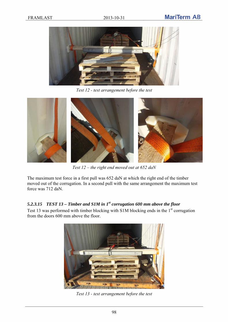
FRAMLAST 2013-10-31
98
Test 12 - test arrangement before the test
Test 12 – the right end moved out at 652 daN The maximum test force in a first pull was 652 daN at which the right end of the timber moved out of the corrugation. In a second pull with the same arrangement the maximum test force was 712 daN.
5.2.3.15 TEST 13 – Timber and S1M in 1st corrugation 600 mm above the floor
Test 13 was performed with timber blocking with S1M blocking ends in the 1st corrugation from the doors 600 mm above the floor.
Test 13 - test arrangement before the test
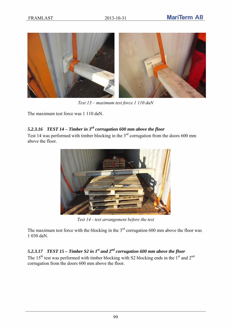
FRAMLAST 2013-10-31
99
Test 13 – maximum test force 1 110 daN The maximum test force was 1 110 daN.
5.2.3.16 TEST 14 – Timber in 3rd corrugation 600 mm above the floor
Test 14 was performed with timber blocking in the 3rd corrugation from the doors 600 mm above the floor.
Test 14 - test arrangement before the test The maximum test force with the blocking in the 3rd corrugation 600 mm above the floor was 1 030 daN.
5.2.3.17 TEST 15 – Timber S2 in 1st and 2nd corrugation 600 mm above the floor
The 15th test was performed with timber blocking with S2 blocking ends in the 1st and 2nd corrugation from the doors 600 mm above the floor.
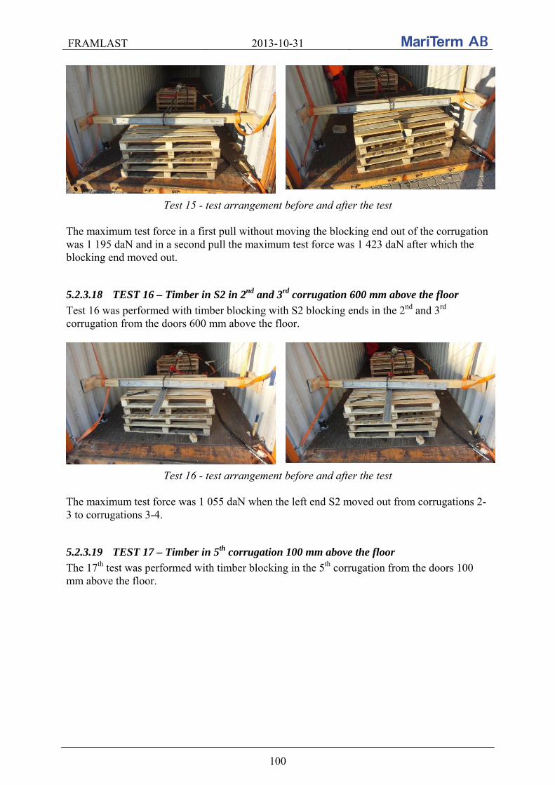
FRAMLAST 2013-10-31
100
Test 15 - test arrangement before and after the test The maximum test force in a first pull without moving the blocking end out of the corrugation was 1 195 daN and in a second pull the maximum test force was 1 423 daN after which the blocking end moved out.
5.2.3.18 TEST 16 – Timber in S2 in 2nd and 3rd corrugation 600 mm above the floor
Test 16 was performed with timber blocking with S2 blocking ends in the 2nd and 3rd corrugation from the doors 600 mm above the floor.
Test 16 - test arrangement before and after the test The maximum test force was 1 055 daN when the left end S2 moved out from corrugations 2-3 to corrugations 3-4.
5.2.3.19 TEST 17 – Timber in 5th corrugation 100 mm above the floor
The 17th test was performed with timber blocking in the 5th corrugation from the doors 100 mm above the floor.

FRAMLAST 2013-10-31
101
Test 17 - test arrangement before and after the test The maximum test force was 1 365 daN and at 1 355 daN the timber broke.
5.2.3.20 TEST 18 – Timber in S2 in 4th and 5th corrugation 100 mm above the floor
The 18th test was performed with timber blocking with S2 blocking ends in the 2nd and 3rd corrugation from the doors 100 mm above the floor.
Test 18 - test arrangement before and after the test The maximum test force was 1 463 daN at which the timber broke.
5.2.3.21 Summary
In the table below a summary of the results of the maximum test force for timber blocking in container side wall corrugations is presented.

FRAMLAST 2013-10-31
102
Test no. Corrugation Timber
dimensions [mm] Blocking
ends Blocking height
[mm]
Maximum test force
[daN]
1 1 1001002 422 - 1 000 1 435
1 1 1001002 422 - 1 000 1 370
1 1 1001002 422 - 1 000 1 035
11 1 1001002 422 - 600 982
11 1 1001002 422 - 600 927 5 3 1001002 422 - 1 000 682
14 3 1001002 422 - 600 1 030
4 5 1001002 422 - 1 000 915
17 5 1001002 422 - 100 1 355
3 1 1001002 320 S1M 1 000 832
13 1 1001002 320 S1M 600 1 110
8 3 1001002 320 S1M 1 000 467
12 3 1001002 320 S1M 600 652
12 3 1001002 320 S1M 600 712
2 5 1001002 320 S1M 1 000 445
7 1 1001002 320 S1V 1 000 932
6 3 1001002 320 S1V 1 000 830
6 3 1001002 320 S1V 1 000 700
10 1-2 1001002 320 S2 1 000 1 060
15 1-2 1001002 320 S2 600 1 423
16 2-3 1001002 320 S2 600 1 055
9 4-5 1001002 320 S2 1 000 787
18 4-5 1001002 320 S2 100 1 463 The tests at the floor level have shown that the strength of the blocking arrangement is more a question of the strength of the timber than of the blocking capacity of the corrugations. When the blocking is higher up the blocking capacity of the blocking device is mainly influenced by the friction in the contact area between the blocking device and the container wall. In some cases a second pull with the same arrangement at the same locations could take up less force. This is probably as the friction in the contact area has decreased slightly after the first pull. A summary of the tests is shown below.
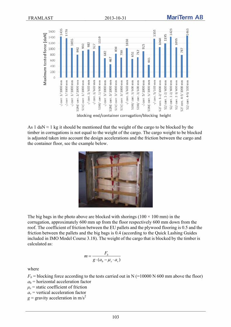
FRAMLAST 2013-10-31
103
As 1 daN ≈ 1 kg it should be mentioned that the weight of the cargo to be blocked by the timber in corrugations is not equal to the weight of the cargo. The cargo weight to be blocked is adjusted taken into account the design accelerations and the friction between the cargo and the container floor, see the example below.
The big bags in the photo above are blocked with shorings (100 × 100 mm) in the corrugation, approximately 600 mm up from the floor respectively 600 mm down from the roof. The coefficient of friction between the EU pallets and the plywood flooring is 0.5 and the
friction between the pallets and the big bags is 0.4 (according to the Quick Lashing Guides included in IMO Model Course 3.18). The weight of the cargo that is blocked by the timber is
calculated as:
)( vsh
b
aag
Fm
where
Fb = blocking force according to the tests carried out in N (=10000 N 600 mm above the floor) ah = horizontal acceleration factor μs = static coefficient of friction av = vertical acceleration factor g = gravity acceleration in m/s2

FRAMLAST 2013-10-31
104
During sea transport in sea area C the horizontal (forward and rearward) and vertical acceleration factors are 0.4 respectively 0.2. Corresponding acceleration factors during road transport are 0.8 respectively 1.0 forward and 0.5 respectively 1.0 rearward (according to EN 12195-1:2010). The maximum weight of the blocked cargo by the two timbers is:
Sea area C: 6371)2.04.04.0(81.9
100002
m kg
Road transport, forward: 5097)0.14.08.0(81.9
100002
m kg
Road transport, rearward: 20387)0.14.05.0(81.9
100002
m kg
The weight of the cargo which is blocked by one shoring in the corrugation for different coefficient of friction during road and sea area C transport is shown below. The Fb used in the table below is Fb = 34 000 N at the floor level, Fb = 10 000 N 600 mm above floor and Fb = 9 000 N 1 000 mm above floor. Note that the Fb value at the floor level is derived from the tests in Gothenburg.
Weight of cargo blocked by one shoring in the corrugation (ton)
Coefficient of friction μ
Height from floor / roof
(mm)
Road transport, forward
Road transport, rearward
Sea area C transport
0.2 0 5.8 11.6 9.6
600 1.7 3.4 2.8 1 000 1.5 3.1 2.5
0.3 0 6.9 17.3 10.2
600 2.0 5.1 3.0 1 000 1.8 4.6 2.7
0.4 0 8.7 34.7 10.8
600 2.5 10.2 3.2 1 000 2.3 9.2 2.9
0.5 0 11.6 Unlimited 11.6
600 3.4 Unlimited 3.4 1 000 3.1 Unlimited 3.1
0.6 0 17.3 Unlimited 12.4
600 5.1 Unlimited 3.6 1 000 4.6 Unlimited 3.3
0.7 0 34.7 Unlimited 13.3
600 10.2 Unlimited 3.9 1 000 9.2 Unlimited 3.5
It is proposed that procedures for how to test the strength in the corrugation should be included in the next revision of standard ISO 1496-1.
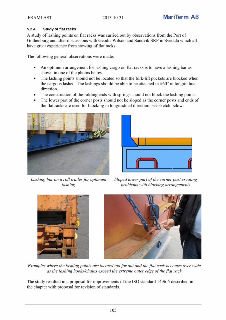
FRAMLAST 2013-10-31
105
5.2.4 Study of flat racks
A study of lashing points on flat racks was carried out by observations from the Port of Gothenburg and after discussions with Geodis Wilson and Sandvik SRP in Svedala which all have great experience from stowing of flat racks. The following general observations were made:
An optimum arrangement for lashing cargo on flat racks is to have a lashing bar as shown in one of the photos below.
The lashing points should not be located so that the fork-lift pockets are blocked when the cargo is lashed. The lashings should be able to be attached in ±60° in longitudinal direction.
The construction of the folding ends with springs should not block the lashing points. The lower part of the corner posts should not be sloped as the corner posts and ends of
the flat racks are used for blocking in longitudinal direction, see sketch below.
Lashing bar on a roll trailer for optimum lashing
Sloped lower part of the corner post creating problems with blocking arrangements
Examples where the lashing points are located too far out and the flat rack becomes over wide as the lashing hooks/chains exceed the extreme outer edge of the flat rack
The study resulted in a proposal for improvements of the ISO standard 1496-5 described in the chapter with proposal for revision of standards.

FRAMLAST 2013-10-31
106
6. EXAMINATION OF FUTURE CTUs A questionnaire about requirements and wishes of future cargo transport units regarding dimensions, cargo securing, cargo handling etc, were sent out to about 90 companies in Sweden. The results of the examination are shown below.
6.1 Method and implementation
A great number of companies within the transport industry were contacted to fill in a list of requirements and wishes of future cargo transport units. About 90 companies received the questionnaire and over 60 answers were obtained. The companies were divided into the following sectors: forest products as reels, pallets, pulp and timber packages (10 replies), steel products as coils, format, sheets and long cargo (4 replies), other metal products as metal powder and copper wire (3 replies), chemical products as big bags, small bags on pallets, barrels, drums and IBC’s (8 replies), general cargo, consignors, as IKEA, Ericsson, McNeil, Ecophon and Vin&Sprit (7 replies), forwarders (8 replies), hauliers (2 replies), other wholesale cargo as flooring and VVS-products (3 replies), machinery products as VCE, Tetra Pak, Dynapac and Sandvik SRP (5 replies), mechanical industry as ABB, Siemens and Cardo Door (5 replies), automotive industry as Volvo, Scania and SKF, basic industry as cable drums and glass (2 replies), foodstuff (2 replies) and concrete elements (1 reply). The companies were asked to aside some time to complete the questionnaire for requirements, needs and wishes on cargo transport units for its specific cargo and its prerequisites. Many of the companies were also interviewed over the phone. The questionnaire was divided into the following headings: dimensions, transportability, cargo handling, cargo securing, cargo care and marking as well as documentation. Each category under each heading was judged as an absolute requirement, a strong desire, a wish, or if it is irrelevant to their cargo during transport within Europe. The companies were also asked to specify their requirements or preferences with any quantitative information and/or comments. The results of the completed questionnaires are reported and summarized in different diagrams in the next section. The companies were also asked to fill in their amount of transported tons per year and in the summary below each answer are weighted in relation to the number of tons transported for each company. The requirements from the large companies shine through stronger than the smaller companies with less transported tons. The questionnaire was constructed as follow:
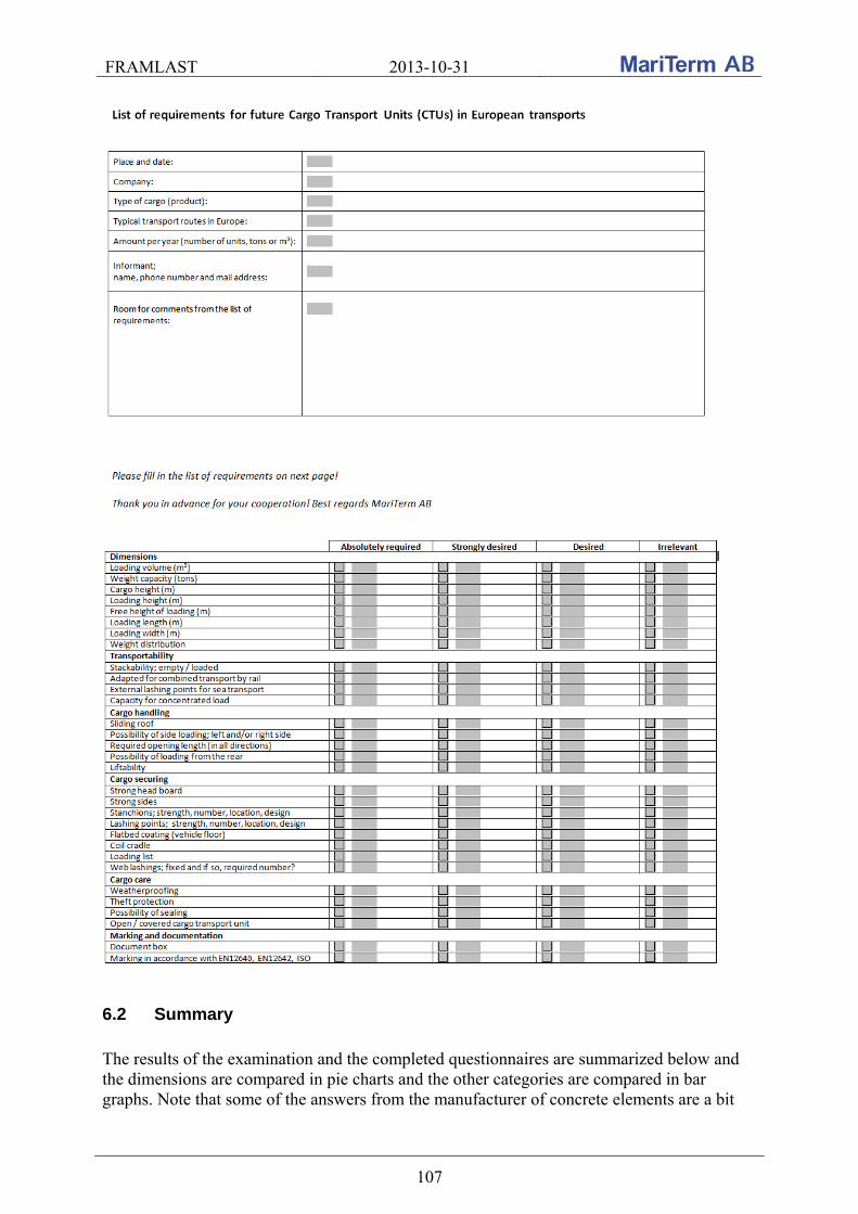
FRAMLAST 2013-10-31
107
6.2 Summary
The results of the examination and the completed questionnaires are summarized below and the dimensions are compared in pie charts and the other categories are compared in bar graphs. Note that some of the answers from the manufacturer of concrete elements are a bit
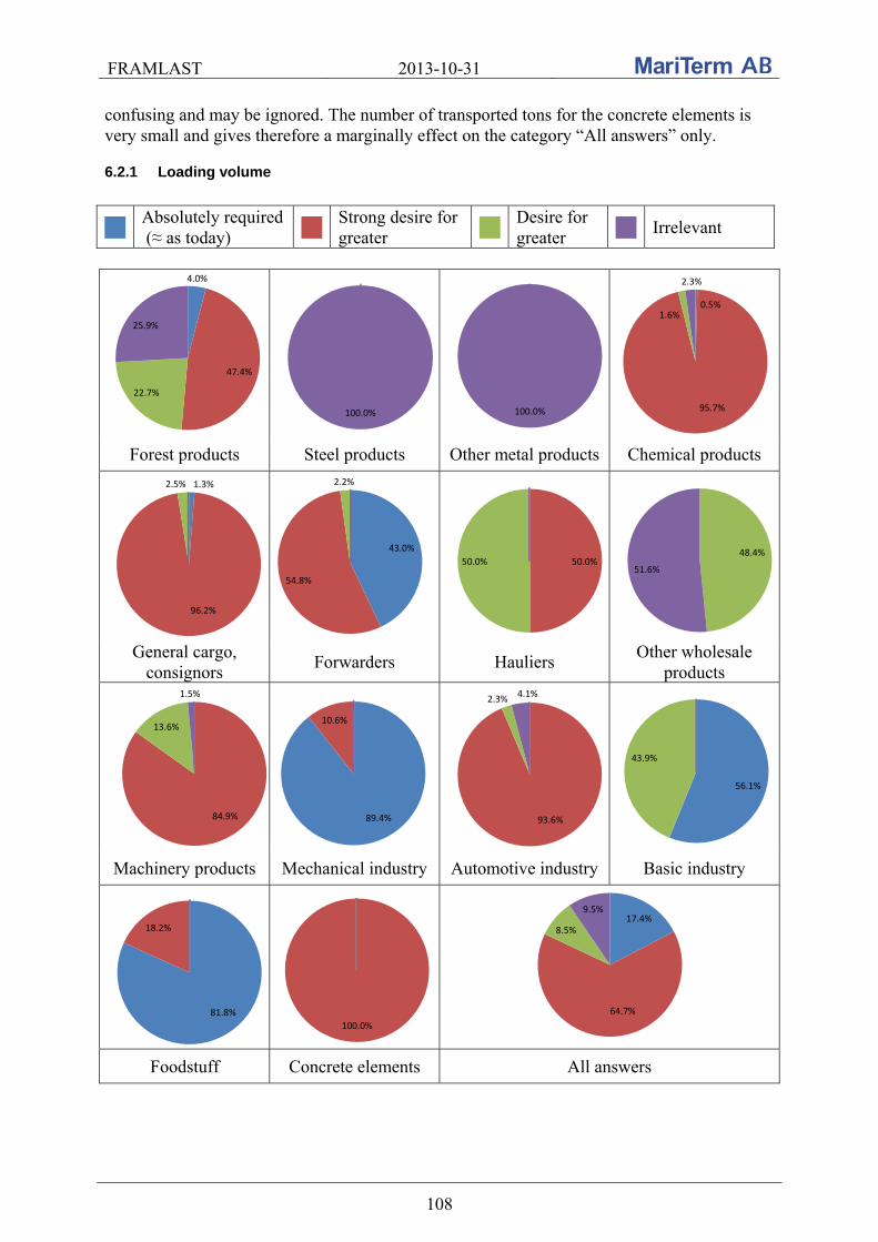
FRAMLAST 2013-10-31
108
confusing and may be ignored. The number of transported tons for the concrete elements is very small and gives therefore a marginally effect on the category “All answers” only.
6.2.1 Loading volume
Absolutely required (≈ as today)
Strong desire for greater
Desire for greater
Irrelevant
4.0%
47.4%
22.7%
25.9%
100.0% 100.0%
0.5%
95.7%
1.6%
2.3%
Forest products Steel products Other metal products Chemical products
1.3%
96.2%
2.5%
43.0%
54.8%
2.2%
50.0%50.0%48.4%
51.6%
General cargo, consignors
Forwarders Hauliers Other wholesale
products
84.9%
13.6%
1.5%
89.4%
10.6%
93.6%
2.3%4.1%
56.1%
43.9%
Machinery products Mechanical industry Automotive industry Basic industry
81.8%
18.2%
100.0%
17.4%
64.7%
8.5%
9.5%
Foodstuff Concrete elements All answers
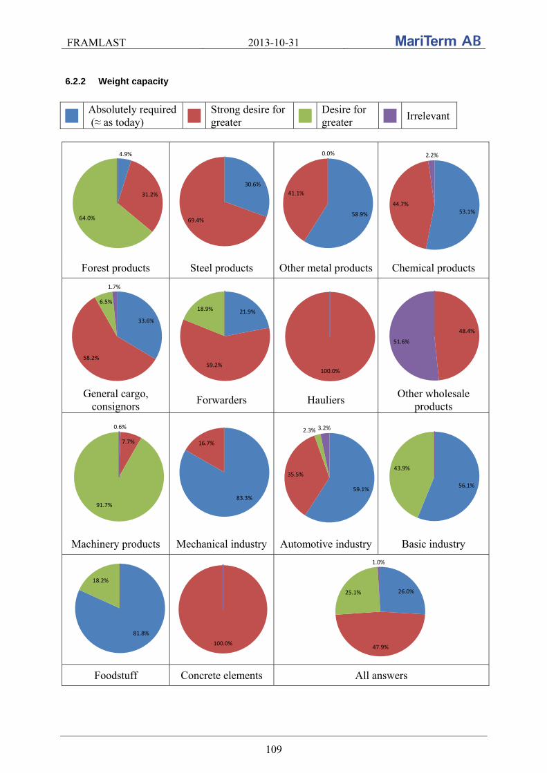
FRAMLAST 2013-10-31
109
6.2.2 Weight capacity
Absolutely required (≈ as today)
Strong desire for greater
Desire for greater
Irrelevant
4.9%
31.2%
64.0%
30.6%
69.4%58.9%
41.1%
0.0%
53.1%44.7%
2.2%
Forest products Steel products Other metal products Chemical products
33.6%
58.2%
6.5%
1.7%
21.9%
59.2%
18.9%
100.0%
48.4%
51.6%
General cargo, consignors
Forwarders Hauliers Other wholesale
products
0.6%
7.7%
91.7%83.3%
16.7%
59.1%
35.5%
2.3% 3.2%
56.1%
43.9%
Machinery products Mechanical industry Automotive industry Basic industry
81.8%
18.2%
100.0%
26.0%
47.9%
25.1%
1.0%
Foodstuff Concrete elements All answers

FRAMLAST 2013-10-31
110
6.2.3 Loading height
Absolutely required (≈ as today)
Strong desire for greater
Desire for greater
Irrelevant
4.0%
32.4%
53.4%
10.1% 17.5%
82.5%
100.0%87.1%
4.1%8.8%
Forest products Steel products Other metal products Chemical products
89.4%
4.2%4.0%2.4%
26.3%
43.9%
29.8%
100.0%96.8%
3.2%
General cargo, consignors
Forwarders Hauliers Other wholesale
products
93.2%
6.8%
37.9%
56.1%
6.1%
2.3%
96.8%
0.9%
100.0%
Machinery products Mechanical industry Automotive industry Basic industry
81.8%
18.2%
100.0%
32.6%
41.6%
20.1%
5.7%
Foodstuff Concrete elements All answers

FRAMLAST 2013-10-31
111
6.2.4 Free height at loading
Absolutely required (≈ as today)
Strong desire for greater
Desire for greater
Irrelevant
4.0%
32.4%
53.4%
10.1% 17.5%
82.5%
100.0%
87.1%
4.1%8.8%
Forest products Steel products Other metal products Chemical products
89.4%
4.2%4.0%2.4%
26.3%
32.9%
40.8%
100.0% 96.8%
3.2%
General cargo, consignors
Forwarders Hauliers Other wholesale
products
93.2%
6.8%
37.9%
56.1%
6.1%
2.3%
96.8%
0.9%
56.1%
43.9%
Machinery products Mechanical industry Automotive industry Basic industry
100.0% 100.0%
32.9%
37.7%
23.7%
5.7%
Foodstuff Concrete elements All answers
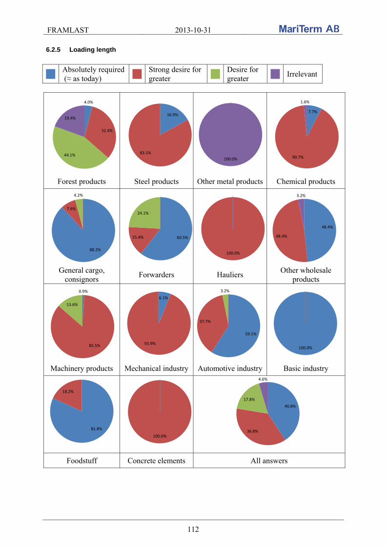
FRAMLAST 2013-10-31
112
6.2.5 Loading length
Absolutely required (≈ as today)
Strong desire for greater
Desire for greater
Irrelevant
4.0%
32.4%
44.1%
19.4%16.9%
83.1%
100.0%
7.7%
90.7%
1.6%
Forest products Steel products Other metal products Chemical products
88.2%
7.6%
4.2%
60.5%15.4%
24.1%
100.0%
48.4%
48.4%
3.2%
General cargo, consignors
Forwarders Hauliers Other wholesale
products
0.9%
85.5%
13.6%
6.1%
93.9%
59.1%
37.7%
3.2%
100.0%
Machinery products Mechanical industry Automotive industry Basic industry
81.8%
18.2%
100.0%
40.8%
36.8%
17.8%
4.6%
Foodstuff Concrete elements All answers
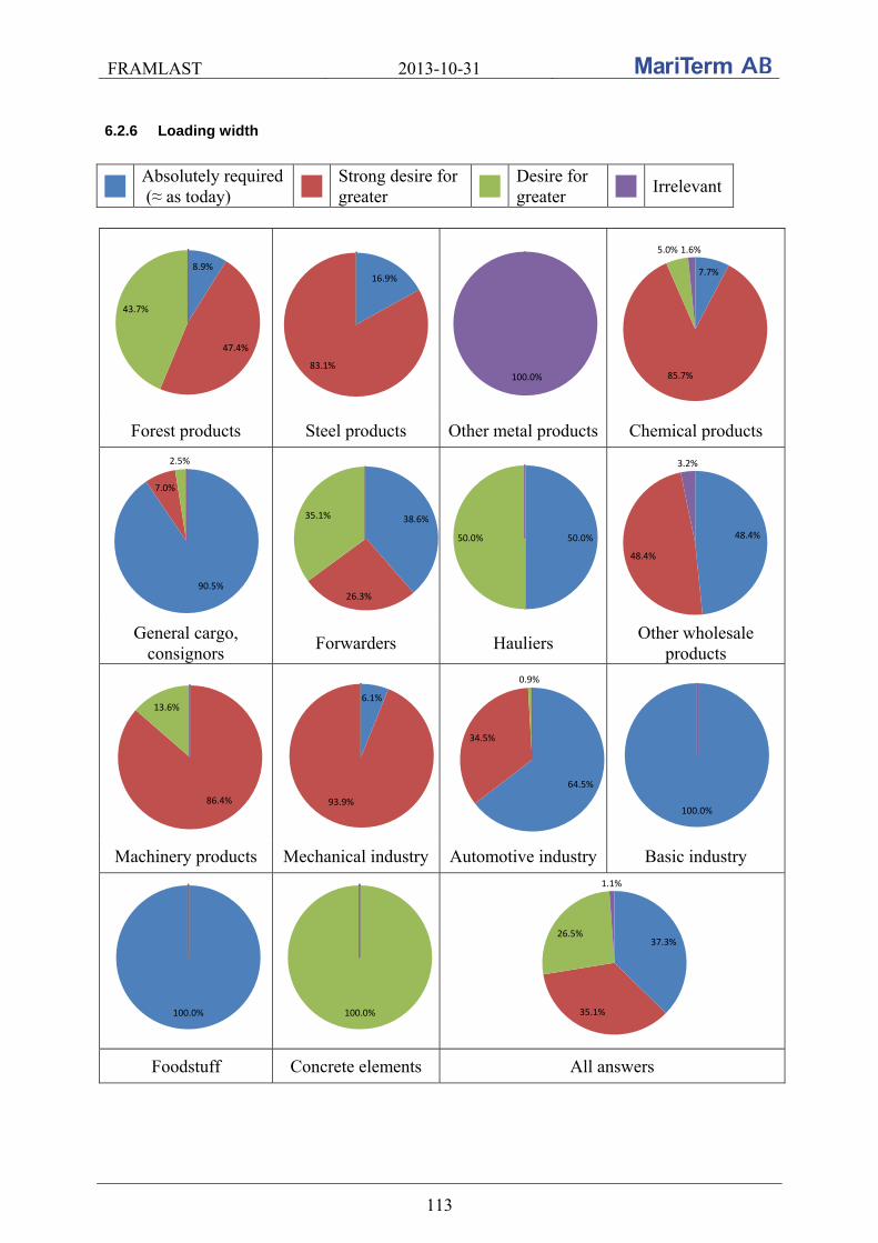
FRAMLAST 2013-10-31
113
6.2.6 Loading width
Absolutely required (≈ as today)
Strong desire for greater
Desire for greater
Irrelevant
8.9%
47.4%
43.7%
16.9%
83.1%100.0%
7.7%
85.7%
5.0% 1.6%
Forest products Steel products Other metal products Chemical products
90.5%
7.0%
2.5%
38.6%
26.3%
35.1%
50.0%50.0% 48.4%
48.4%
3.2%
General cargo, consignors
Forwarders Hauliers Other wholesale
products
86.4%
13.6%6.1%
93.9%
64.5%
34.5%
0.9%
100.0%
Machinery products Mechanical industry Automotive industry Basic industry
100.0% 100.0%
37.3%
35.1%
26.5%
1.1%
Foodstuff Concrete elements All answers
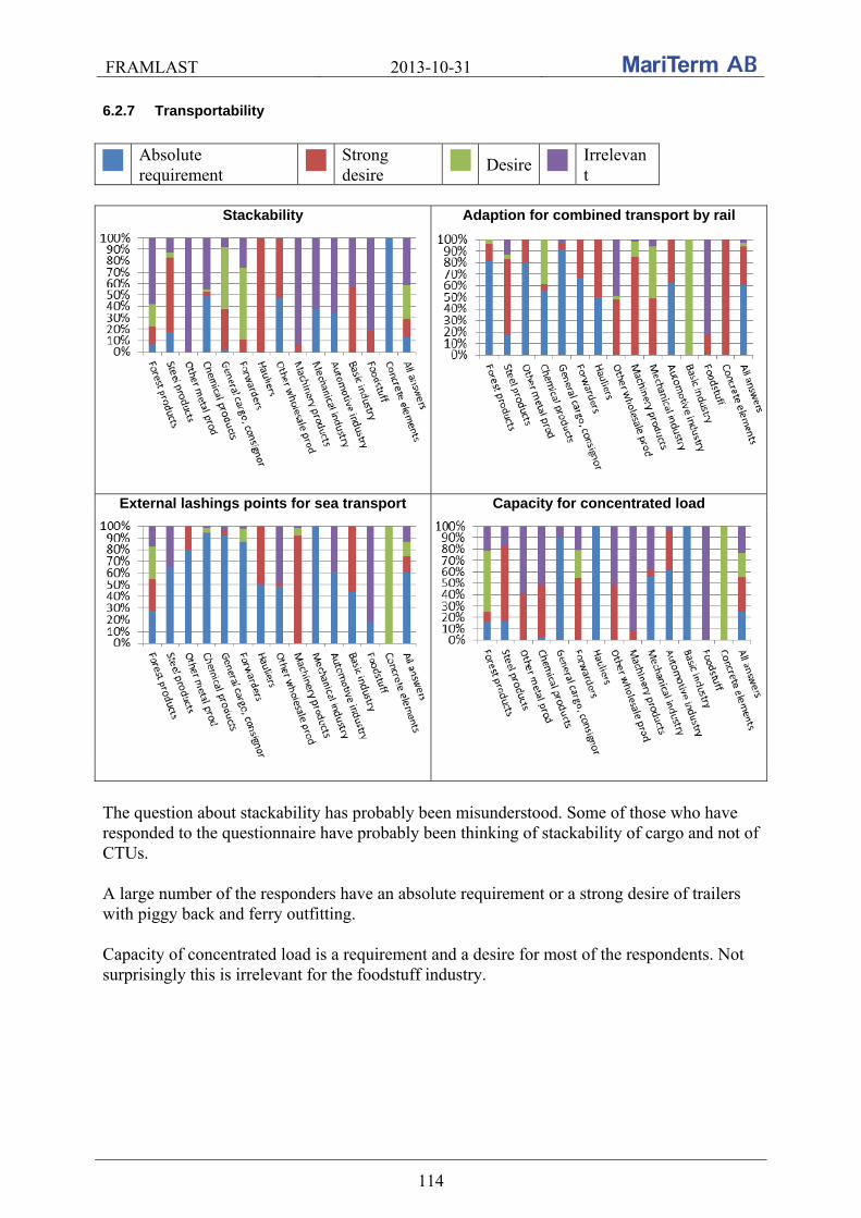
FRAMLAST 2013-10-31
114
6.2.7 Transportability
Absolute requirement
Strong desire
Desire
Irrelevant
Stackability Adaption for combined transport by rail
External lashings points for sea transport Capacity for concentrated load
The question about stackability has probably been misunderstood. Some of those who have responded to the questionnaire have probably been thinking of stackability of cargo and not of CTUs. A large number of the responders have an absolute requirement or a strong desire of trailers with piggy back and ferry outfitting. Capacity of concentrated load is a requirement and a desire for most of the respondents. Not surprisingly this is irrelevant for the foodstuff industry.

FRAMLAST 2013-10-31
115
6.2.8 Cargo handling
Absolute requirement
Strong desire
Desire
Irrelevant
Sliding roof Possibility of side loading
Required opening length Possibility of loading from the rear
Liftability

FRAMLAST 2013-10-31
116
Most of the responders have an absolute requirement of possibility of loading from the side. Surprisingly many have made notes about requirements and desire of possibility of loading from both sides and possibilities of opening the whole side.
6.2.9 Cargo securing
Absolute requirement
Strong desire
Desire
Irrelevant
Strong headboard Strong sides
Stanchions Lashing points
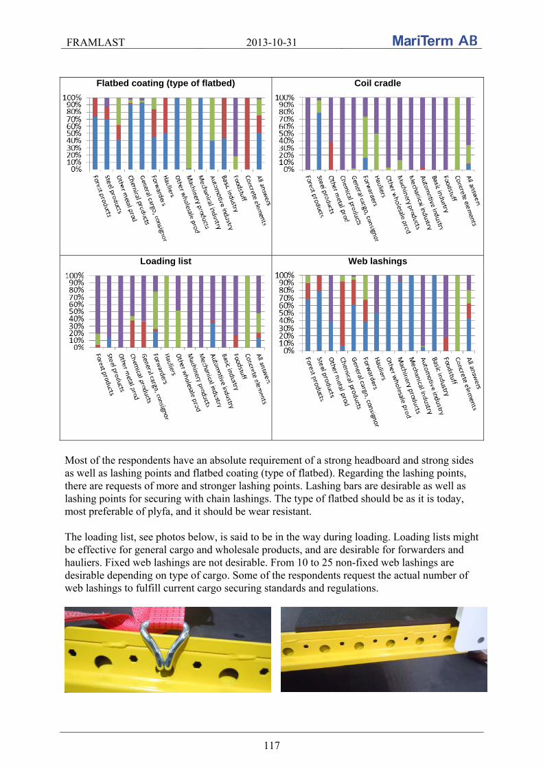
FRAMLAST 2013-10-31
117
Flatbed coating (type of flatbed) Coil cradle
Loading list Web lashings
Most of the respondents have an absolute requirement of a strong headboard and strong sides as well as lashing points and flatbed coating (type of flatbed). Regarding the lashing points, there are requests of more and stronger lashing points. Lashing bars are desirable as well as lashing points for securing with chain lashings. The type of flatbed should be as it is today, most preferable of plyfa, and it should be wear resistant. The loading list, see photos below, is said to be in the way during loading. Loading lists might be effective for general cargo and wholesale products, and are desirable for forwarders and hauliers. Fixed web lashings are not desirable. From 10 to 25 non-fixed web lashings are desirable depending on type of cargo. Some of the respondents request the actual number of web lashings to fulfill current cargo securing standards and regulations.

FRAMLAST 2013-10-31
118
6.2.10 Cargo care
Absolute requirement
Strong desire
Desire
Irrelevant
Weatherproofing Theft protection
Possibility of sealing Covered cargo transport unit
All respondents have requirement of weatherproof and covered CTUs. Most of the cargo is to be protected against water, moisture and dirt. Theft protection and possibility of sealing is becoming more and more important, and this is an absolute requirement and a strong desire especially for machinery products, the foodstuff industry, other metal products, consignor of general cargo and forwarders. Regarding possibility of sealing, this is an absolute requirement to fulfil duty requirements. Note that the answers from the manufacturer of concrete elements are neglected in this category.

FRAMLAST 2013-10-31
119
6.2.11 Marking and documentation
Absolute requirement
Strong desire
Desire
Irrelevant
Document box Marking in accordance with EN12642, EN12640
This category of questions was probably answered without knowing what EN 12642 and EN 12640 really is. Most likely there is a lack of knowledge of the European standards for cargo securing and cargo securing equipment. Marking in accordance with these standards is an absolute requirement to 55 % of the cargo only. The foodstuff industry for example, is answering that this is irrelevant for them but in actuality the foodstuff industry probably requires strong headboard and sides to fulfil the current cargo securing regulations.

FRAMLAST 2013-10-31
120
7. EXPECTED DEVELOPMENT IN THE MEDIUM TERM This chapter contains an analysis of the examination and discussions about expected parameters of cargo transport unit over the next 20 years for the European transports.
7.1 Analysis of the examination
The answers of the questionnaire in terms of the dimensions were quite expected. The companies participating in the examination were asked to fill in their amount of transported tons per year. The summarizing is weighted in relation to the number of tons transported for each company. This means that if one company for example has filled in an absolute requirement of higher CTUs, all cargo from this company is registered as an absolute requirement even if some products only require higher units. Regarding loading volume almost 75 % has strong desire or desire of a greater loading volume, for example forest, chemical and machinery products, automotive industry, consignors of general cargo and hauliers. The mechanical, basic and foodstuff industry are pleased with the loading volume in today’s cargo transport units while the volume is irrelevant for steel and other heavy metal products. Regarding requirements for the loading height just above 60 % has strong desire or desire of larger heights, for example forest products, forwarders as well as mechanical and automotive industry. This is the dimension that has the greatest number of products that is satisfied with today’s CTUs, for example chemical, machinery and other wholesale products, basic and foodstuff industry, hauliers and consignor of general cargo. Similar answers were received regarding free loading height. Forest, steel, chemical and machinery products, hauliers, other wholesale cargo and mechanical industry have strong desire or desire of longer vehicles (approximately 76 %) while the automotive, basic and foodstuff industry, consignor of general cargo and forwarders are pleased with the cargo transport units regarding loading length of today. The loading length is irrelevant for other metal products. Almost 62 % of the products (forest, steel, chemical, machinery products, forwarders and mechanical industry) have a strong desire or desire of increased loading width in CTUs. The loading width is irrelevant for other metal products while forwarders for general cargo and the automotive, basic and foodstuff industry is pleased with the loading width in CTUs of today. The answers of the questionnaire in terms of dimensions were approximately as expected; the forest industry wants larger CTUs (volume, length, width as well as height) and larger weight capacity, the steel and metal industry wants increased weight capacity while the loading volume is irrelevant, the chemical industry, consignors of general cargo, forwarders as well as hauliers wants increased loading volume, machinery products want increased loading volume and weight capacity and the basic industry and the foodstuff is quite satisfied with the CTUs of today.
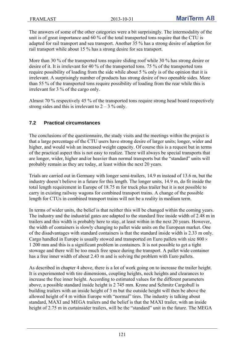
FRAMLAST 2013-10-31
121
The answers of some of the other categories were a bit surprisingly. The intermodality of the unit is of great importance and 60 % of the total transported tons require that the CTU is adapted for rail transport and sea transport. Another 35 % has a strong desire of adaption for rail transport while about 15 % has a strong desire for sea transport. More than 30 % of the transported tons require sliding roof while 30 % has strong desire or desire of it. It is irrelevant for 40 % of the transported tons. 75 % of the transported tons require possibility of loading from the side while about 5 % only is of the opinion that it is irrelevant. A surprisingly number of products has strong desire of two openable sides. More than 55 % of the transported tons require possibility of loading from the rear while this is irrelevant for 3 % of the cargo only. Almost 70 % respectively 45 % of the transported tons require strong head board respectively strong sides and this is irrelevant to 2 – 3 % only.
7.2 Practical circumstances
The conclusions of the questionnaire, the study visits and the meetings within the project is that a large percentage of the CTU users have strong desire of larger units; longer, wider and higher, and would wish an increased weight capacity. Of course this is a request but in terms of the practical aspect this is not easy to realize. There will always be special transports that are longer, wider, higher and/or heavier than normal transports but the “standard” units will probably remain as they are today, at least within the next 20 years. Trials are carried out in Germany with longer semi-trailers, 14.9 m instead of 13.6 m, but the industry doesn’t believe in a future for this length. The longer units, 14.9 m, do fit inside the total length requirement in Europe of 18.75 m for truck plus trailer but it is not possible to carry in existing railway wagons for combined transport trains. A change of the possible length for CTUs in combined transport trains will not be a reality in medium term. In terms of wider units, the belief is that neither this will be changed within the coming years. The industry and the industrial gates are adapted to the standard free inside width of 2.48 m in trailers and this width is probably here to stay, at least within in the next 20 years. However, the width of containers is slowly changing to pallet wide units on the European market. One of the disadvantages with standard containers is that the standard inside width is 2.33 m only. Cargo handled in Europe is usually stowed and transported on Euro pallets with size 800 1 200 mm and this is a significant problem in containers. It is not possible to get a tight stowage and there will be too much free space during the transport. A pallet wide container has a free inner width of about 2.43 m and is solving the problem with Euro pallets. As described in chapter 4 above, there is a lot of work going on to increase the trailer height. It is experimented with tire dimensions, coupling heights, neck heights and clearances to increase the free inner height. According to estimated values for the different parameters above, a possible standard inside height is 2 745 mm. Krone and Schmitz Cargobull is building trailers with an inside height of 3 m but the outside height will then be above the allowed height of 4 m within Europe with “normal” tires. The industry is talking about standard, MAXI and MEGA trailers and the belief is that the MAXI trailer, with an inside height of 2.75 m in curtainsider trailers, will be the “standard” unit in the future. The MEGA
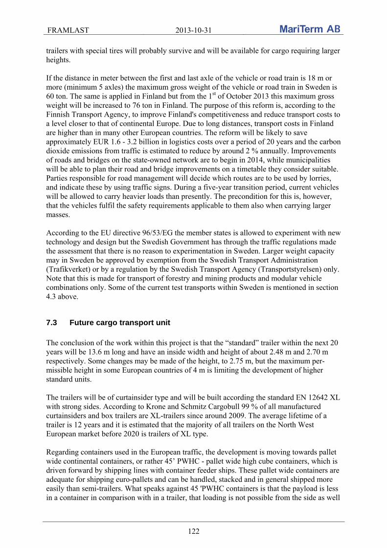
FRAMLAST 2013-10-31
122
trailers with special tires will probably survive and will be available for cargo requiring larger heights. If the distance in meter between the first and last axle of the vehicle or road train is 18 m or more (minimum 5 axles) the maximum gross weight of the vehicle or road train in Sweden is 60 ton. The same is applied in Finland but from the 1st of October 2013 this maximum gross weight will be increased to 76 ton in Finland. The purpose of this reform is, according to the Finnish Transport Agency, to improve Finland's competitiveness and reduce transport costs to a level closer to that of continental Europe. Due to long distances, transport costs in Finland are higher than in many other European countries. The reform will be likely to save approximately EUR 1.6 - 3.2 billion in logistics costs over a period of 20 years and the carbon dioxide emissions from traffic is estimated to reduce by around 2 % annually. Improvements of roads and bridges on the state-owned network are to begin in 2014, while municipalities will be able to plan their road and bridge improvements on a timetable they consider suitable. Parties responsible for road management will decide which routes are to be used by lorries, and indicate these by using traffic signs. During a five-year transition period, current vehicles will be allowed to carry heavier loads than presently. The precondition for this is, however, that the vehicles fulfil the safety requirements applicable to them also when carrying larger masses. According to the EU directive 96/53/EG the member states is allowed to experiment with new technology and design but the Swedish Government has through the traffic regulations made the assessment that there is no reason to experimentation in Sweden. Larger weight capacity may in Sweden be approved by exemption from the Swedish Transport Administration (Trafikverket) or by a regulation by the Swedish Transport Agency (Transportstyrelsen) only. Note that this is made for transport of forestry and mining products and modular vehicle combinations only. Some of the current test transports within Sweden is mentioned in section 4.3 above.
7.3 Future cargo transport unit
The conclusion of the work within this project is that the “standard” trailer within the next 20 years will be 13.6 m long and have an inside width and height of about 2.48 m and 2.70 m respectively. Some changes may be made of the height, to 2.75 m, but the maximum per-missible height in some European countries of 4 m is limiting the development of higher standard units. The trailers will be of curtainsider type and will be built according the standard EN 12642 XL with strong sides. According to Krone and Schmitz Cargobull 99 % of all manufactured curtainsiders and box trailers are XL-trailers since around 2009. The average lifetime of a trailer is 12 years and it is estimated that the majority of all trailers on the North West European market before 2020 is trailers of XL type. Regarding containers used in the European traffic, the development is moving towards pallet wide continental containers, or rather 45’ PWHC - pallet wide high cube containers, which is driven forward by shipping lines with container feeder ships. These pallet wide containers are adequate for shipping euro-pallets and can be handled, stacked and in general shipped more easily than semi-trailers. What speaks against 45 'PWHC containers is that the payload is less in a container in comparison with in a trailer, that loading is not possible from the side as well

FRAMLAST 2013-10-31
123
as the tough competition for the container traffic against the cheap trailer transports. The prospects for container traffic would be improved by a change in the regulatory environment for larger gross weight of the transport of 45’ containers, and not 40’ containers only. The inside height of a high cube container is about 2695 mm instead of 2385 mm as in a standard container. For information it should be mentioned that almost all new standard 40’ maritime containers are high cube containers. The summary of the results of the work in the FRAMLAST project is that the XL-classed curtain sided trailer and the pallet wide high cube (PWHC) container, with approximate dimensions according to below, will probably dominate the market within the 20 coming years. The market for MEGA trailers and hybrid units like the CUSI is supposed to be limited. It is a great wish that new allowed combinations are built up around existing standard modules not to jeopardize the development of intermodal traffic. For specific flows however other vehicle length, width and height may be considered.
Probable inside dimensions of the future CTUs within the 20 coming years
Length (m) Width (m) Height (m) Payload (kg) Tare (kg)
Semi-trailer 13.6 2.48 2.75 26150 - 28750 6250 - 6600
45’ PWHC 13.55 2.43 2.69 29550* 4450*
*) A container chassi, with an approximate weight of 5 ton, must be used for the road transport and is added to the gross weight of the equipage.
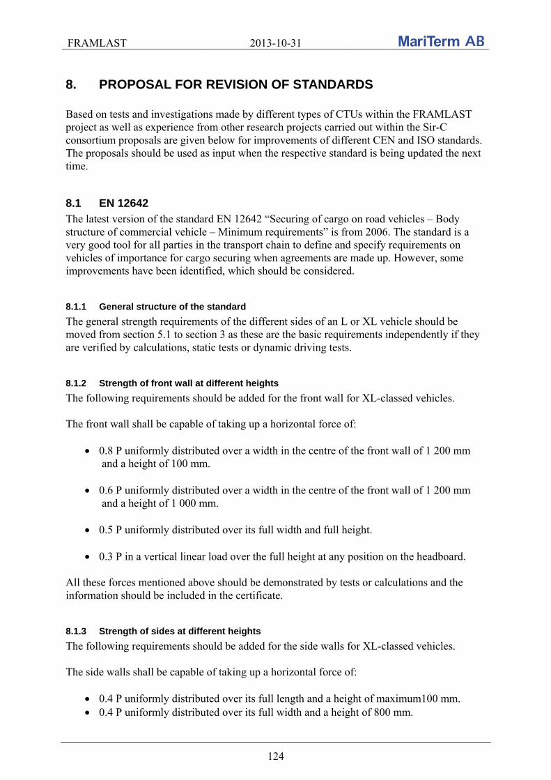
FRAMLAST 2013-10-31
124
8. PROPOSAL FOR REVISION OF STANDARDS Based on tests and investigations made by different types of CTUs within the FRAMLAST project as well as experience from other research projects carried out within the Sir-C consortium proposals are given below for improvements of different CEN and ISO standards. The proposals should be used as input when the respective standard is being updated the next time.
8.1 EN 12642
The latest version of the standard EN 12642 “Securing of cargo on road vehicles – Body structure of commercial vehicle – Minimum requirements” is from 2006. The standard is a very good tool for all parties in the transport chain to define and specify requirements on vehicles of importance for cargo securing when agreements are made up. However, some improvements have been identified, which should be considered.
8.1.1 General structure of the standard
The general strength requirements of the different sides of an L or XL vehicle should be moved from section 5.1 to section 3 as these are the basic requirements independently if they are verified by calculations, static tests or dynamic driving tests.
8.1.2 Strength of front wall at different heights
The following requirements should be added for the front wall for XL-classed vehicles. The front wall shall be capable of taking up a horizontal force of:
0.8 P uniformly distributed over a width in the centre of the front wall of 1 200 mm and a height of 100 mm.
0.6 P uniformly distributed over a width in the centre of the front wall of 1 200 mm and a height of 1 000 mm.
0.5 P uniformly distributed over its full width and full height.
0.3 P in a vertical linear load over the full height at any position on the headboard.
All these forces mentioned above should be demonstrated by tests or calculations and the information should be included in the certificate.
8.1.3 Strength of sides at different heights
The following requirements should be added for the side walls for XL-classed vehicles. The side walls shall be capable of taking up a horizontal force of:
0.4 P uniformly distributed over its full length and a height of maximum100 mm. 0.4 P uniformly distributed over its full width and a height of 800 mm.
FRAMLAST 2013-10-31
125
0.4 P uniformly distributed over its full width and full height.
The side walls shall also be capable of taking up vertical linear loads with a longitudinal distance of 600 mm. The sum of the linear loads shall correspond to a horizontal force of 0.4 P and shall be uniformly distributed over the full length of the side and reach from the floor up to 75% of the height of the side. The side walls shall be capable of taking up 0.02 P in a vertical linear load over the full vehicle height at any position on the side. All these forces mentioned above should be demonstrated by tests or calculations and the information should be included in the certificate.
8.1.4 Requirements on curtain sides to fulfil railway requirements
Specifications of a test for curtain side deflections that can be accepted by the railway authorities should be developed and a new class for railway approved curtain sides should be included in the standard.
8.1.5 Floor strength
A floor of a vehicle should have the same strength as the floor of a container and should be tested according to the same forklift test as is specified in the container standard ISO 1496-1. However, new test requirements are to be developed, see section 8.4.9.
8.1.6 Dynamic driving tests
If a dynamic driving test has been used to verify the strength of a side wall, this should be marked on the marking sign complemented with the type of cargo that was used for the tests.
8.1.7 Concentrated load / load distribution
A vehicle shall be marked with a load distribution diagram or table showing max allowed cargo weight depending on the cargoes center of gravity. Further, the center of the platform bed shall be marked.
8.1.8 Test of stanchions
In the standard a test procedure and marking of the strength of stanchions should be included.
8.1.9 Marking signs
The requirements for marking should be complemented by the following requirements:
The German version of the standard should be corrected so that it contains the same requirements as the English version of having separate signs of compliance with the standard on independent signs as well as on the identification plate.
FRAMLAST 2013-10-31
126
The marking signs shall be located outside on both sides of the vehicle on the side walls or on the front wall. In addition signs shall be located inside at the rear part on both sides maximum 500 mm from the rear end of the vehicle.
On the marking signs, in addition to the existing information, number of laths to fulfil the requirements shall be included. It is proposed that the marking signs of XL trailers should be coordinated with the ILU code and the labelling requirements from the railway.
8.2 EN 12640
The latest version of the standard EN 12640 “Securing of cargo on road vehicles – Lashing points on commercial vehicles for goods transportation – Minimum requirements and testing” is from 2000.
8.2.1 Scope
The current version of the standard does not specify any requirements for lashing points in box-type bodies which creates problems in daily use of such vehicles because when such vehicles are carrying cargo smaller than loading area it is not possible to block it and it must be lashed. It is proposed that also such type of vehicles is included in the scope of the standard and they shall have floor lashing points.
8.2.2 Identification
Section 3 of the standard specifies requirements that lashing points shall be identified e.g. EN 12640-20. It is proposed to delete this requirement as this is part of the testing of lashing point fixed to the vehicle which can give different results as what is identified on lashing point itself. Marking required according section 6 of the standard is sufficient.
8.2.3 Design requirements
Lashing points shall be designed to accommodate lashing forces applied in any direction, not as it is defined in current standard (conical area) because when low and heavy cargo must be lashed vertical lashing angles below 30° are frequently used. Lashing points must also be designed for lashing of over width cargo wider than loading area (platform vehicles) or cargo wider more than 50 mm transverse from the lashing point. If a lashing device (e.g. lashing winch) is supposed to be used in a limited lashing angle only it can be tested only for those lashing angles.
8.2.4 Number of lashing points
Because European vehicles frequently carry pallets 1200 800 mm and current requirements for distance of lashing points are not suitable when pallets are loaded two per section it is proposed that: - the distance from front or rear end wall shall not be greater than 400 mm - the distance between two adjacent lashing points on one side shall be not more than 800 mm. Lashing points should also be installed in the rear end of the vehicle, along the rear end wall.

FRAMLAST 2013-10-31
127
Pallets lashed on a vehicle with lashing points according to the current standard EN 12640
8.2.5 Lashing bars
Current standard does not specify any requirements for lashing bars with holes which nowadays are frequently used in Europe. For the purposes of load securing it is important that lashing bars are constructed in a way that it is possible to lash cargo in any direction including over width cargo. Usually lashing bars are not suitable for small vertical lashing angles below 30° (see photo below) because the lashing hook is bending. Frequently used lashing bars are not suitable for lashing of over width cargo.
Not suitable position of holes on lashing bar for low vertical lashing angles
It is proposed that lashing bars must be suitable for vertical lashing angles from 0° to 90°. When over width cargo is transported and there is no other lashing point for such a purpose on a vehicle, lashing bars shall be constructed for vertical lashing angles -90° to + 90°. It is proposed that minimum strength of lashing bars must be 8000 daN/m.
8.2.6 Testing directions
Current standard does not specify the testing for low angles of inclination below 30°. Therefore it is proposed that each lashing point must be tested for angles of inclination from 0° to 90° and angles of rotation from 0° to 180°. When designed for over width cargo each lashing point must be tested for angles of inclination from -90° to +90° and angles of rotation from 0° to 360°. If the construction of lashing points is symmetrical in tested directions or lashing points are to be supposed to be used in specific lashing angles only it is not necessary to test the lashing point in all specified directions. The proposed lashing angles are summarized in a table and a sketch according to below.
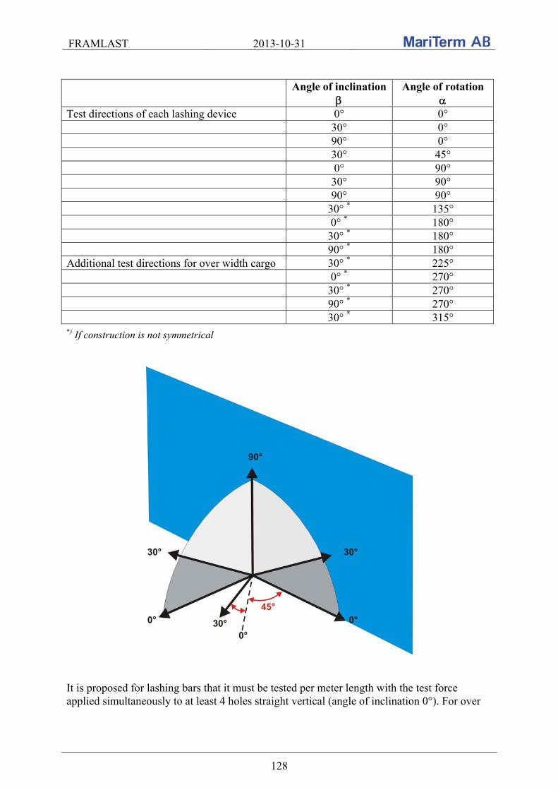
FRAMLAST 2013-10-31
128
Angle of inclination
Angle of rotation
Test directions of each lashing device 0° 0° 30° 0° 90° 0° 30° 45° 0° 90° 30° 90° 90° 90° 30° * 135° 0° * 180° 30° * 180° 90° * 180° Additional test directions for over width cargo 30° * 225° 0° * 270° 30° * 270° 90° * 270° 30° * 315°
*) If construction is not symmetrical
It is proposed for lashing bars that it must be tested per meter length with the test force applied simultaneously to at least 4 holes straight vertical (angle of inclination 0°). For over

FRAMLAST 2013-10-31
129
width cargo straight horizontal the test force is proposed to be applied to at least 4 holes straight horizontal (angle of inclination 90°).
8.2.7 Test frame
Current standard does not clearly define the purpose of the test frame. It is proposed to delete this requirement and leave required testing directions to apply test forces only.
8.2.8 Marking
The marking of lashing points varies on vehicles so it is proposed that the standard shall require that marking plate shall be of blue colour with white lettering and white border, minimum 200 150 mm. It shall indicate the place where lashing points are located on the vehicle and lashing capacity of each lashing point.
8.3 EN 283
The latest version of the standard EN 283 “Swap bodies – Testing” is from 1991. The standard is very old and needs updating. It is proposed that the parts of the standard that contains requirements on front, end and side walls are updated with the requirements in the standard EN 12642 for XL-classed vehicles.
8.4 ISO 1496-1 Dry container
The latest version of the standard ISO 1496-1 “Series 1 freight containers – Specification and testing – Part 1: General cargo containers for general purposes” is from 1990 and five amendments have been published, the latest in 2006. The standard needs to be updated according to the amendments. It is today unclear what is applicable.
8.4.1 Minimum number of anchoring and lashing points and location of anchoring points
The standard ISO 1496-1 does not specify the minimum number of anchoring and lashing points in general purpose maritime containers. The standard indicates typical number of anchoring points only. The requirements should be complemented by the following requirements, with the minimum number of cargo securing devices specified in a table: Containers Cargo securing device
Location 1EEE, 1EE
1AAA, 1AA,
1A, 1AX
1BBB, 1BB, 1B,
1BX
1CCC, 1CC, 1C,
1CX
1DD, 1D, 1DX
Anchor points Each bottom side rail
18 16 12 8 4
Lashing points Each top side rail 18 16 12 8 4
Each corner post 4 The cost to install extra anchoring and lashing points is limited.
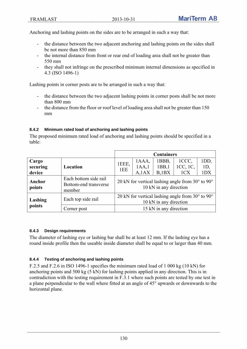
FRAMLAST 2013-10-31
130
Anchoring and lashing points on the sides are to be arranged in such a way that:
- the distance between the two adjacent anchoring and lashing points on the sides shall be not more than 850 mm
- the internal distance from front or rear end of loading area shall not be greater than 550 mm
- they shall not infringe on the prescribed minimum internal dimensions as specified in 4.3 (ISO 1496-1)
Lashing points in corner posts are to be arranged in such a way that:
- the distance between the two adjacent lashing points in corner posts shall be not more than 800 mm
- the distance from the floor or roof level of loading area shall not be greater than 150
mm
8.4.2 Minimum rated load of anchoring and lashing points
The proposed minimum rated load of anchoring and lashing points should be specified in a table:
Containers
Cargo securing device
Location 1EEE,1EE
1AAA,1AA,1A,1AX
1BBB,1BB,1B,1BX
1CCC, 1CC, 1C,
1CX
1DD, 1D, 1DX
Anchor points
Each bottom side rail Bottom-end transverse member
20 kN for vertical lashing angle from 30° to 90° 10 kN in any direction
Lashing points
Each top side rail 20 kN for vertical lashing angle from 30° to 90°
10 kN in any direction Corner post 15 kN in any direction
8.4.3 Design requirements
The diameter of lashing eye or lashing bar shall be at least 12 mm. If the lashing eye has a round inside profile then the useable inside diameter shall be equal to or larger than 40 mm.
8.4.4 Testing of anchoring and lashing points
F.2.5 and F.2.6 in ISO 1496-1 specifies the minimum rated load of 1 000 kg (10 kN) for anchoring points and 500 kg (5 kN) for lashing points applied in any direction. This is in contradiction with the testing requirement in F.3.1 where such points are tested by one test in a plane perpendicular to the wall where fitted at an angle of 45° upwards or downwards to the horizontal plane.

FRAMLAST 2013-10-31
131
ISO 1496-1:1990/Amd.2:1998(E) - Figure E.1 – Cargo securing devices – Examples of directions of application of test loadings
Testing of cargo securing devices is thus not sufficient and they should be tested in the following directions:
- All anchoring and lashing points (lashing eyes) on the sides should be tested in directions defined in the figure below.
Proposed directions of application of test loadings for anchoring points Maximum allowed tolerance of testing angles is ± 5°.
- Lashing bars in corner posts:
in a horizontal plane where lashing bars are fitted perpendicular to the lashing bar in the centre of lashing bar
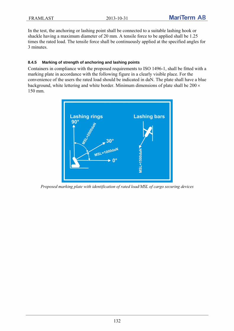
FRAMLAST 2013-10-31
132
In the test, the anchoring or lashing point shall be connected to a suitable lashing hook or shackle having a maximum diameter of 20 mm. A tensile force to be applied shall be 1.25 times the rated load. The tensile force shall be continuously applied at the specified angles for 3 minutes.
8.4.5 Marking of strength of anchoring and lashing points
Containers in compliance with the proposed requirements to ISO 1496-1, shall be fitted with a marking plate in accordance with the following figure in a clearly visible place. For the convenience of the users the rated load should be indicated in daN. The plate shall have a blue background, white lettering and white border. Minimum dimensions of plate shall be 200 150 mm.
Proposed marking plate with identification of rated load/MSL of cargo securing devices

FRAMLAST 2013-10-31
133
8.4.6 Test of global strength for concentrated cargoes
The global strength of typical designs of box containers allows for dense and concentrated cargoes to be loaded over a short length of the container, but under the ISO test regime tests with weights corresponding to the dynamic forces for the full payload is carried out with the load uniformly distributed over the entire floor area only. However, in practice, only bulk cargo may be perfectly evenly distributed over the entire floor and in order to allow for the full capacity of the global strength to be utilized it is proposed to introduce a test with concentrated cargo in the ISO standard 1496-1. Such a test should be carried out in accordance with the following:
The container should be elevated from the ground, resting on supports at the corner posts only
A test load of 200% of the rated payload (Pg) should be placed at the longitudinal center of the container
The test load should be uniformly distributed over 50% of the length of the container and supported in a manner so that the load is distributed to the side beams with an equal load on each side beam.
After removal of the load, the structure of the container shall not exhibit any deformation.
Proposed test for concentrated loads
8.4.7 End wall strength 60%
For the design of cargo securing by blocking in containers the strength of end walls tested to 0.4Pg is not sufficient for road transport where inertial forces are considered to be 0.8Pg. Therefore it is proposed that the end walls shall be tested to 0.6 Pg, same as for sidewalls where for sea transport inertial forces are considered to be 0.8 Pg. The requirement of 0.6 Pg for end walls is also used for bulk containers according to the ISO 1496-4:1991 for 1CC, 1C, 1CX, 1D, 1DX containers (section 6.6.2 of the standard). Nowadays there is a frequent use of general purpose containers to carry also the bulk cargo in inlets and flexitanks.
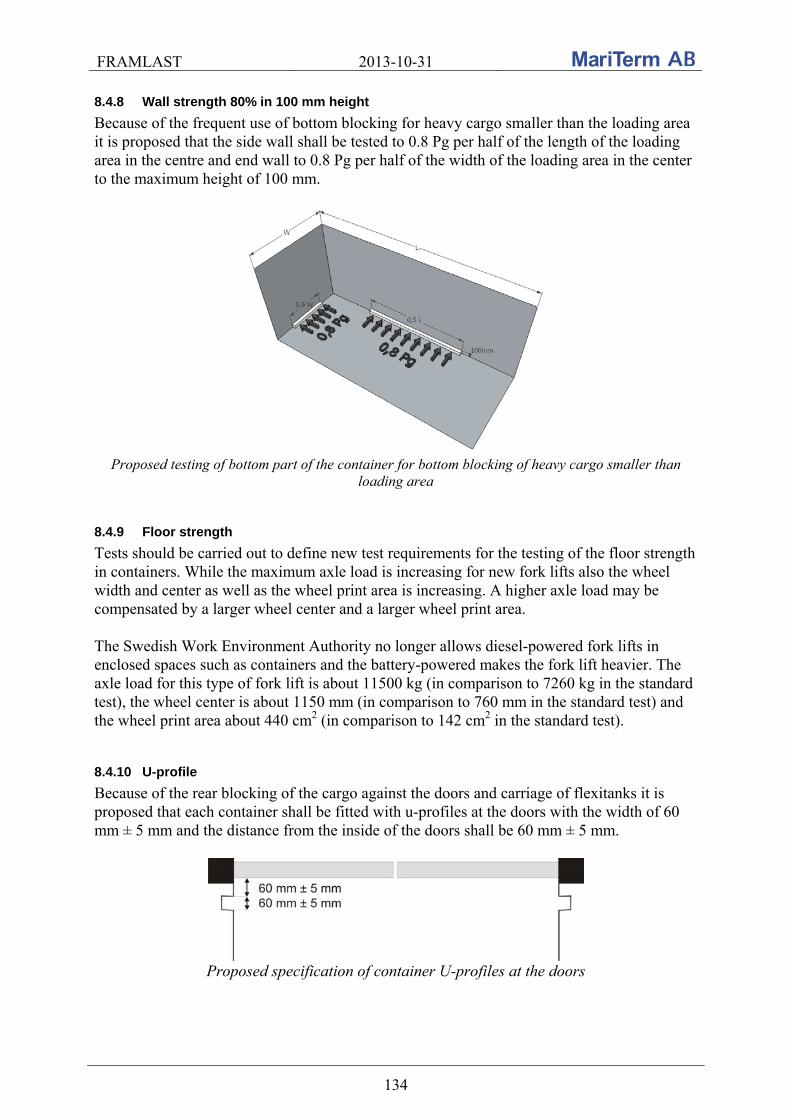
FRAMLAST 2013-10-31
134
8.4.8 Wall strength 80% in 100 mm height
Because of the frequent use of bottom blocking for heavy cargo smaller than the loading area it is proposed that the side wall shall be tested to 0.8 Pg per half of the length of the loading area in the centre and end wall to 0.8 Pg per half of the width of the loading area in the center to the maximum height of 100 mm.
Proposed testing of bottom part of the container for bottom blocking of heavy cargo smaller than
loading area
8.4.9 Floor strength
Tests should be carried out to define new test requirements for the testing of the floor strength in containers. While the maximum axle load is increasing for new fork lifts also the wheel width and center as well as the wheel print area is increasing. A higher axle load may be compensated by a larger wheel center and a larger wheel print area. The Swedish Work Environment Authority no longer allows diesel-powered fork lifts in enclosed spaces such as containers and the battery-powered makes the fork lift heavier. The axle load for this type of fork lift is about 11500 kg (in comparison to 7260 kg in the standard test), the wheel center is about 1150 mm (in comparison to 760 mm in the standard test) and the wheel print area about 440 cm2 (in comparison to 142 cm2 in the standard test).
8.4.10 U-profile
Because of the rear blocking of the cargo against the doors and carriage of flexitanks it is proposed that each container shall be fitted with u-profiles at the doors with the width of 60 mm ± 5 mm and the distance from the inside of the doors shall be 60 mm ± 5 mm.
Proposed specification of container U-profiles at the doors
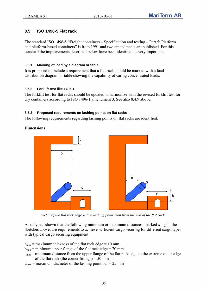
FRAMLAST 2013-10-31
135
8.5 ISO 1496-5 Flat rack
The standard ISO 1496-5 “Freight containers – Specification and testing – Part 5: Platform and platform-based containers” is from 1991 and two amendments are published. For this standard the improvements described below have been identified as very important.
8.5.1 Marking of load by a diagram or table
It is proposed to include a requirement that a flat rack should be marked with a load distribution diagram or table showing the capability of caring concentrated loads.
8.5.2 Forklift test like 1496-1
The forklift test for flat racks should be updated to harmonize with the revised forklift test for dry containers according to ISO 1496-1 amendment 3. See also 8.4.9 above.
8.5.3 Proposed requirements on lashing points on flat racks
The following requirements regarding lashing points on flat racks are identified: Dimensions
e
f
d
g
Sketch of the flat rack edge with a lashing point seen from the end of the flat rack A study has shown that the following minimum or maximum distances, marked a – g in the sketches above, are requirements to achieve sufficient cargo securing for different cargo types with typical cargo securing equipment: amax = maximum thickness of the flat rack edge = 10 mm bmin = minimum upper flange of the flat rack edge = 70 mm cmin = minimum distance from the upper flange of the flat rack edge to the extreme outer edge of the flat rack (the corner fittings) = 50 mm dmax = maximum diameter of the lashing point bar = 25 mm

FRAMLAST 2013-10-31
136
emin = minimum inside distance between the flat rack and the lashing point = 50 mm fmin = minimum outside distance between the flat rack and the lashing point = 60 mm gmin = minimum vertical distance between the lashing point bar and the lower flange = 50 mm The distances are based on the dimensions of frequently used hooks, see pictures below. Strength
The lashing capacity/maximum securing load (LC/MSL) in the lashing points should be at least 5 ton (5000 daN) and this should be indicated on the flat rack by MSL.
Location
The lashing points should be spread out along the whole side of the flat rack with an interval of maximum 600 mm and the first lashing points after the ends should be located as near the ends as possible and maximum 300 mm from the ends of the unit.
General
An optimum arrangement for lashing cargo on flat racks is to have a continues lashing bar as shown in the photos of the roll trailer below.
The lashing points should not be located so that the fork-lift pockets are blocked when
the cargo is lashed. The lashings should be able to be attached in ±60° in longitudinal direction.
The construction of the folding ends with springs should not block the lashing points.
The lower part of the corner posts should not be sloped as the corner posts and ends of
the flat racks often are used for blocking by timber in longitudinal direction as shown on the photos below.
Examples where the lashing points are located too far out and the flat rack becomes over wide as the the lashing hooks/chains exceed the extreme outer edge of the flat rack
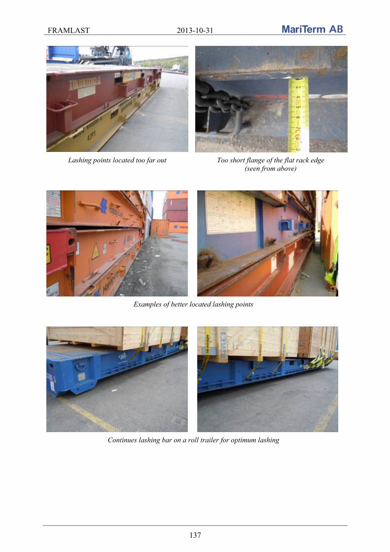
FRAMLAST 2013-10-31
137
Lashing points located too far out Too short flange of the flat rack edge (seen from above)
Examples of better located lashing points
Continues lashing bar on a roll trailer for optimum lashing
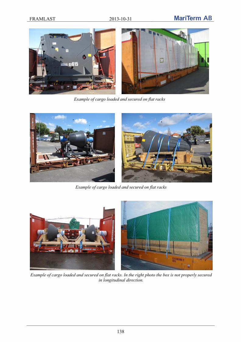
FRAMLAST 2013-10-31
138
Example of cargo loaded and secured on flat racks
Example of cargo loaded and secured on flat racks
Example of cargo loaded and secured on flat racks. In the right photo the box is not properly secured in longitudinal direction.
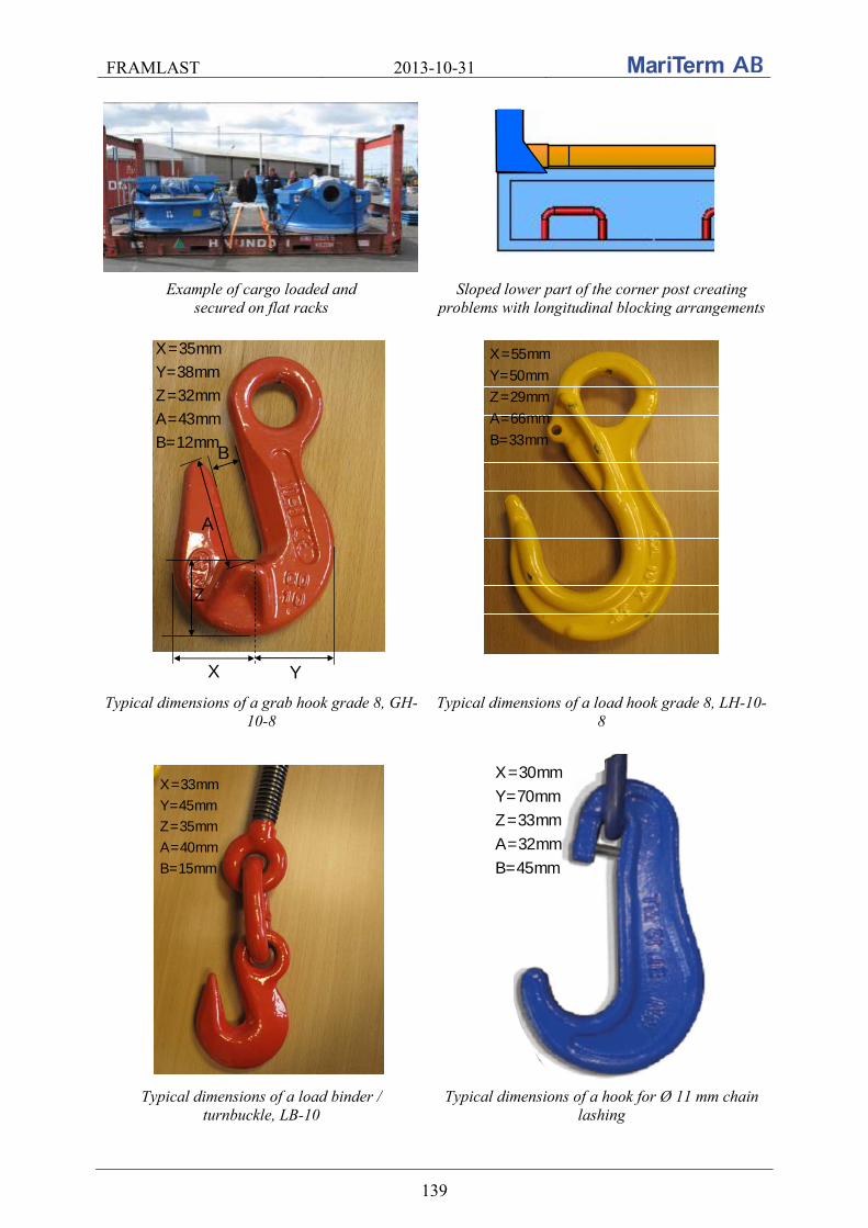
FRAMLAST 2013-10-31
139
Example of cargo loaded and secured on flat racks
Sloped lower part of the corner post creating problems with longitudinal blocking arrangements
X Y
Z
B
A
X=35mm
Y=38mm
Z=32mm
A=43mm
B=12mm
X=55mm
Y=50mm
Z=29mm
A=66mm
B=33mm
Typical dimensions of a grab hook grade 8, GH-10-8
Typical dimensions of a load hook grade 8, LH-10-8
X=33mm
Y=45mm
Z=35mm
A=40mm
B=15mm
X=30mm
Y=70mm
Z=33mm
A=32mm
B=45mm
Typical dimensions of a load binder / turnbuckle, LB-10
Typical dimensions of a hook for Ø 11 mm chain lashing
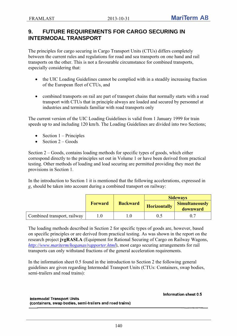
FRAMLAST 2013-10-31
140
9. FUTURE REQUIREMENTS FOR CARGO SECURING IN INTERMODAL TRANSPORT The principles for cargo securing in Cargo Transport Units (CTUs) differs completely between the current rules and regulations for road and sea transports on one hand and rail transports on the other. This is not a favourable circumstance for combined transports, especially considering that:
the UIC Loading Guidelines cannot be complied with in a steadily increasing fraction of the European fleet of CTUs, and
combined transports on rail are part of transport chains that normally starts with a road
transport with CTUs that in principle always are loaded and secured by personnel at industries and terminals familiar with road transports only
The current version of the UIC Loading Guidelines is valid from 1 January 1999 for train speeds up to and including 120 km/h. The Loading Guidelines are divided into two Sections;
Section 1 – Principles Section 2 – Goods
Section 2 – Goods, contains loading methods for specific types of goods, which either correspond directly to the principles set out in Volume 1 or have been derived from practical testing. Other methods of loading and load securing are permitted providing they meet the provisions in Section 1. In the introduction to Section 1 it is mentioned that the following accelerations, expressed in g, should be taken into account during a combined transport on railway:
Forward Backward Sideways
Horizontally Simultaneously
downward
Combined transport, railway 1.0 1.0 0.5 0.7
The loading methods described in Section 2 for specific types of goods are, however, based on specific principles or are derived from practical testing. As was shown in the report on the research project jvgRASLA (Equipment for Rational Securing of Cargo on Railway Wagons, http://www.mariterm/hoganas/rapporter.html), most cargo securing arrangements for rail transports can only withstand fractions of the general acceleration requirements. In the information sheet 0.5 found in the introduction to Section 2 the following general guidelines are given regarding Intermodal Transport Units (CTUs: Containers, swap bodies, semi-trailers and road trains):
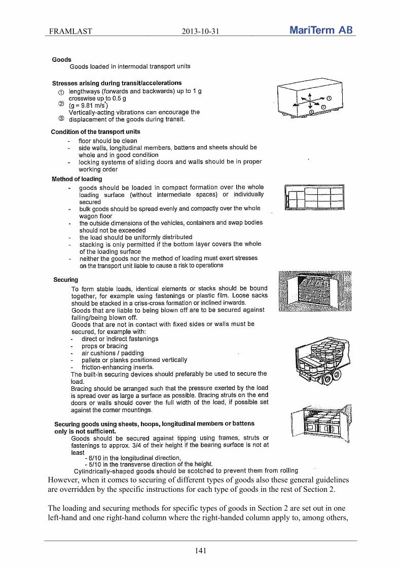
FRAMLAST 2013-10-31
141
However, when it comes to securing of different types of goods also these general guidelines are overridden by the specific instructions for each type of goods in the rest of Section 2. The loading and securing methods for specific types of goods in Section 2 are set out in one left-hand and one right-hand column where the right-handed column apply to, among others,
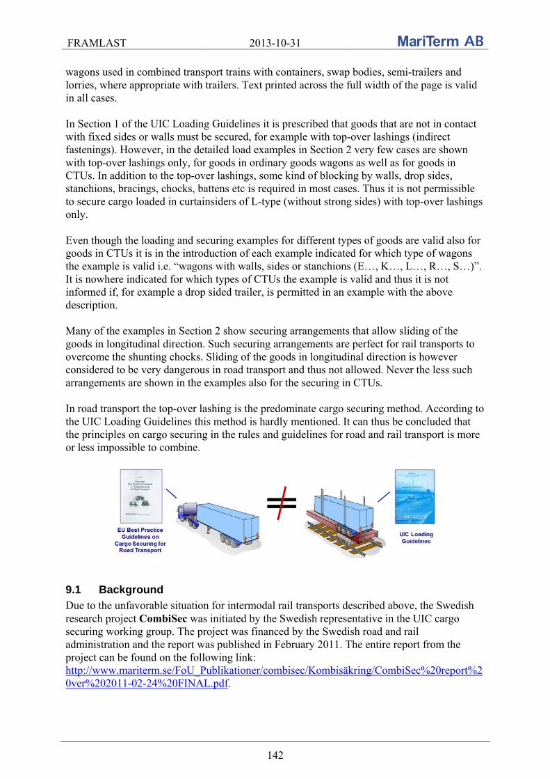
FRAMLAST 2013-10-31
142
wagons used in combined transport trains with containers, swap bodies, semi-trailers and lorries, where appropriate with trailers. Text printed across the full width of the page is valid in all cases. In Section 1 of the UIC Loading Guidelines it is prescribed that goods that are not in contact with fixed sides or walls must be secured, for example with top-over lashings (indirect fastenings). However, in the detailed load examples in Section 2 very few cases are shown with top-over lashings only, for goods in ordinary goods wagons as well as for goods in CTUs. In addition to the top-over lashings, some kind of blocking by walls, drop sides, stanchions, bracings, chocks, battens etc is required in most cases. Thus it is not permissible to secure cargo loaded in curtainsiders of L-type (without strong sides) with top-over lashings only. Even though the loading and securing examples for different types of goods are valid also for goods in CTUs it is in the introduction of each example indicated for which type of wagons the example is valid i.e. “wagons with walls, sides or stanchions (E…, K…, L…, R…, S…)”. It is nowhere indicated for which types of CTUs the example is valid and thus it is not informed if, for example a drop sided trailer, is permitted in an example with the above description. Many of the examples in Section 2 show securing arrangements that allow sliding of the goods in longitudinal direction. Such securing arrangements are perfect for rail transports to overcome the shunting chocks. Sliding of the goods in longitudinal direction is however considered to be very dangerous in road transport and thus not allowed. Never the less such arrangements are shown in the examples also for the securing in CTUs. In road transport the top-over lashing is the predominate cargo securing method. According to the UIC Loading Guidelines this method is hardly mentioned. It can thus be concluded that the principles on cargo securing in the rules and guidelines for road and rail transport is more or less impossible to combine.
9.1 Background
Due to the unfavorable situation for intermodal rail transports described above, the Swedish research project CombiSec was initiated by the Swedish representative in the UIC cargo securing working group. The project was financed by the Swedish road and rail administration and the report was published in February 2011. The entire report from the project can be found on the following link: http://www.mariterm.se/FoU_Publikationer/combisec/Kombisäkring/CombiSec%20report%20ver%202011-02-24%20FINAL.pdf.

FRAMLAST 2013-10-31
143
Within the CombiSec project shunting tests were performed in accordance with UIC Loading Guidelines with 19 cargo transport units supplied by the projects industry representatives. The cargo securing fulfilled the road regulations in 13 of the 19 units only. None of the units were in compliance with the instructions in the UIC Loading Guidelines. Despite this, cargo movements in the longitudinal direction were very limited, and it could be concluded that it is sufficient to secure cargo in cargo transport units for combined road/rail transports according to the road regulations as long as shunting is carried out at the prescribed maximum speed of 4 km/h. During the project, the securing of a wide range of cargoes was additionally documented during test transports of more than 100 units. The selection of units was carried out by two different principles:
3. Multiple units with identical cargo units were documented by industry representatives in the project, throughout the whole transport chain on selected relations.
4. Random units where selected at rail terminals and documented prior to and after the
rail haulage. For each unit the cargo type and properties, type and classification of the cargo transport unit as well as the means of cargo securing were recorded. The original position of the cargo was marked on the platform floor and any movement was noted upon arrival at the destination. The following main conclusions were drawn based on the results of the test transports:
In most inspected units, no signs of significant accelerations in any direction could be detected except in some units in one and the same train, which probably was exposed to large shunting speeds.
There were no indications of significant accelerations in the transverse direction in
any of the inspected units.
There is a significant wandering effect for unlashed cargo during intermodal transports by rail due to vibrations. The movement of the cargo occurred randomly.
The curtain sides of XL trailers have in these test transports proved to be able to safely
contain the cargo within the unit without showing any noticeable deflection, even when the cargo was unlashed.
Indirect lashings (top-over lashings) may be used to safely secure cargo during rail
transports. In all cases, when properly applied, the securing principles for cargo securing during road transports may serve as safe guidelines also for combined transports by rail.
9.1.1 Recommendations of the CombiSec project
Based on the findings in the CombiSec project it has been concluded that the principles set out in the “European Best Practice Guidelines on Cargo Securing for Road Transport” is sufficient also for combined rail transports. It is thus recommended that the UIC Loading
FRAMLAST 2013-10-31
144
Guidelines are complemented with the inclusion of these principles. It is, however, important to bear in mind that a design acceleration in longitudinal direction of 0.5 g (about 5 m/s2) is based on shunting speeds of maximum 4 km/h. To avoid that cargo moves uncontrolled due to vibrations during the rail part of the transports it is recommended that special requirements are provided for cargo securing arrangements to avoid such movements. If the UIC Loading Guidelines are complemented according to these recommendations it is also recommended to approach CEN/TC 168 to get the basic design accelerations for combined rail transports altered to be in line with the accelerations for road transports. This is important not to jeopardize the future increase of combined rail transports as the cargo securing standard EN 12195-1 (2010) might be used to form the bases for a future cargo securing directive within the European Community.
9.1.2 Result of the CombiSec project
Even though contacts were taken by the UIC cargo securing working group it was not possible to obtain a meeting where the results from the CombiSec project were presented during the time of the project. When the FRAMLAST project was started it was thus decided that the results from CombiSec should be brought forward during the work with FRAMLAST. Meetings have been held and contacts have been taken with different parties. After contacts with UIRR, the International Union of Combined Road-Rail Transport Companies, it was decided that MariTerm AB should participate in the Marco Polo financed project Destiny. The project is coordinated by UIRR and MariTerm is responsible for the development of training material for cargo securing in cargo transport units for combined rail transports. Within the Destiny project meetings have been held with the main European combi-operators and a meeting is planned to be held with the UIC cargo securing working group.
9.1.3 Destiny project
DESTINY, which stands for DEployment of STandards for INtermodal efficiency is a co-funded project under the umbrella of the MarcoPolo programme of the European Commission, aims to provide a common learning action to improve efficiency in the intermodal transport chain.
The project, which started on September 1, 2012 will end on November 31, 2014 is developed by a consortium of 8 partners, and relies on the official support of 15 associations operating in the intermodal transport sector.
DESTINY seeks to deploy best practices in the implementation of existing standards related to the identification, marking and codification of ILUs, load securing and handling dangerous goods.
The ultimate goal is to enhance the competitiveness of European intermodal transport and thus contribute to develop greener modes of transport as an alternative to pure-road freight transport in Europe.
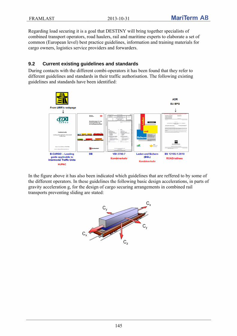
FRAMLAST 2013-10-31
145
Regarding load securing it is a goal that DESTINY will bring together specialists of combined transport operators, road haulers, rail and maritime experts to elaborate a set of common (European level) best practice guidelines, information and training materials for cargo owners, logistics service providers and forwarders.
9.2 Current existing guidelines and standards
During contacts with the different combi-operators it has been found that they refer to different guidelines and standards in their traffic authorisation. The following existing guidelines and standards have been identified:
In the figure above it has also been indicated which guidelines that are reffered to by some of the different operators. In these guidelines the following basic design accelerations, in parts of gravity acceleration g, for the design of cargo securing arrangements in combined rail transports preventing sliding are stated:

FRAMLAST 2013-10-31
146
Guideline
Longitudinally Transversely
Horizontal cx
Vertical cz
Horizontal cy
Vertical cz
B-CARGO & DB 1.0 0.5 0.5 0.5
VDI 2700-7 & BGL UIC Loading Guidelines
1.0 0.7 0.5 0.7
EN 12195-1:2010 Rail 1.0 1.0 0.5 0.7
EN 12195-1:2010 Road Forward 0.8
Backward 0.5 1.0 0.5 1.0
CTU Code Combined rail transport 0.5 1.0 0.5 1.0
It can be seen from the table that the basic design accelerations differs considerably, which also give considerably different requirements in terms of number of lashings. The values in the table indicated for the CTU Code are these agreed upon during the third meeting of the UNECE cargo securing expert group in October 2012.
9.3 Effect of the different guidelines and standards
To illustrate the differences between the regulations in terms of accelerations a number of examples of different kind of cargo and stowing in trailers and containers are shown below. Example 1: A wooden box is loaded in a trailer for a combined rail transport. The box weighs 20 tons and the static friction is static = 0.45 and the dynamic friction dynamic = 0.34.
With calculation principles and factors in accordance with the respective regulations the required number of top-over lashings to prevent sliding in different directions is as follows:
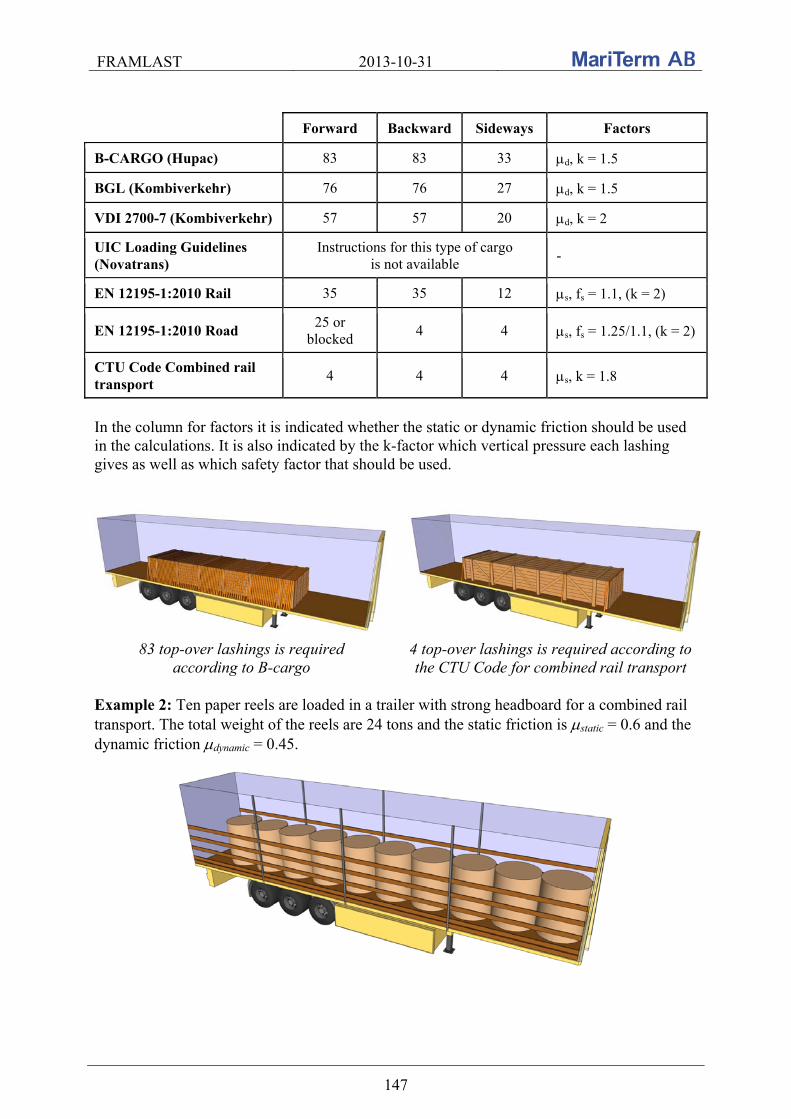
FRAMLAST 2013-10-31
147
Forward Backward Sideways Factors
B-CARGO (Hupac) 83 83 33 d, k = 1.5
BGL (Kombiverkehr) 76 76 27 d, k = 1.5
VDI 2700-7 (Kombiverkehr) 57 57 20 d, k = 2
UIC Loading Guidelines (Novatrans)
Instructions for this type of cargo is not available
-
EN 12195-1:2010 Rail 35 35 12 s, fs = 1.1, (k = 2)
EN 12195-1:2010 Road 25 or
blocked 4 4 s, fs = 1.25/1.1, (k = 2)
CTU Code Combined rail transport
4 4 4 s, k = 1.8
In the column for factors it is indicated whether the static or dynamic friction should be used in the calculations. It is also indicated by the k-factor which vertical pressure each lashing gives as well as which safety factor that should be used.
83 top-over lashings is required according to B-cargo
4 top-over lashings is required according to the CTU Code for combined rail transport
Example 2: Ten paper reels are loaded in a trailer with strong headboard for a combined rail transport. The total weight of the reels are 24 tons and the static friction is static = 0.6 and the dynamic friction dynamic = 0.45.
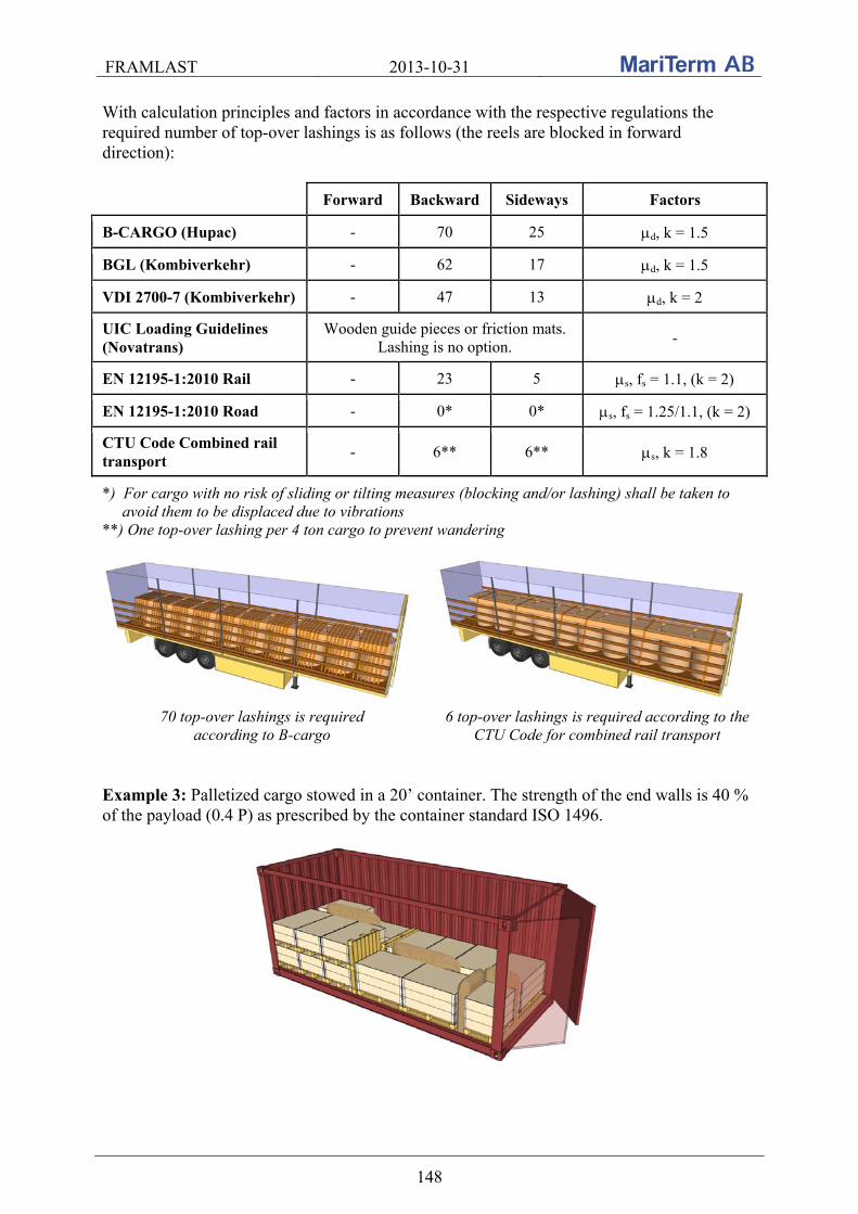
FRAMLAST 2013-10-31
148
With calculation principles and factors in accordance with the respective regulations the required number of top-over lashings is as follows (the reels are blocked in forward direction):
Forward Backward Sideways Factors
B-CARGO (Hupac) - 70 25 d, k = 1.5
BGL (Kombiverkehr) - 62 17 d, k = 1.5
VDI 2700-7 (Kombiverkehr) - 47 13 d, k = 2
UIC Loading Guidelines (Novatrans)
Wooden guide pieces or friction mats. Lashing is no option.
-
EN 12195-1:2010 Rail - 23 5 s, fs = 1.1, (k = 2)
EN 12195-1:2010 Road - 0* 0* s, fs = 1.25/1.1, (k = 2)
CTU Code Combined rail transport
- 6** 6** s, k = 1.8
*) For cargo with no risk of sliding or tilting measures (blocking and/or lashing) shall be taken to avoid them to be displaced due to vibrations **) One top-over lashing per 4 ton cargo to prevent wandering
70 top-over lashings is required according to B-cargo
6 top-over lashings is required according to the CTU Code for combined rail transport
Example 3: Palletized cargo stowed in a 20’ container. The strength of the end walls is 40 % of the payload (0.4 P) as prescribed by the container standard ISO 1496.
FRAMLAST 2013-10-31
149
With the acceleration factors in accordance with the respective regulations the required dynamic and static coefficient of friction is according to the table below in order not to overstress the end walls. The relation between the static and dynamic friction is set to: (dynamic = 0.75 static).
dynamic static Filling ratio*
B-CARGO (Hupac) 1.20 1.60 48 (at µd)
BGL (Kombiverkehr) 0.86 1.14 52 (at µd)
VDI 2700-7 (Kombiverkehr) 0.86 1.14 52 (at µd)
UIC Loading Guidelines (Novatrans) 0.86 1.14 52 (at µd)
EN 12195-1:2010 Rail 0.45 0.60 73 (at µs)
EN 12195-1:2010 Road 0.30 0.40 100 (at µs)
Packing Code Combined rail transport 0.08 0.10 100 (at µs)
*) dynamic = 0.45 and static = 0.34 The maximum coefficient of friction is 1.0 and B-CARGO is requiring a dynamic coefficient of friction of 1.20 not to overload the end walls of the container! With the relevant coefficients of friction in this example, dynamic = 0.45 and static = 0.34, the filling ratio according to the different regulations is according to the rightmost column according to above. The maximum possible filling ratio according to B-CARGO is thus 48 % only of the maximum payload capacity of the container. The above examples show that the principles, factors and accelerations in most of the guidelines and standards are unrealistic and impossible to use in reality.
9.4 Current proposals on international rules and regulations
In this section current proposals on international rules and regulations regarding combined transport, dangerous goods as well as pure road and sea transports are described.
9.4.1 Combined Transport: UIC Loading Guidelines
The proposal is to replace the Information sheet 0.5 – Intermodal Transport Unit of the UIC Loading Guidelines Section 2 with the following text:
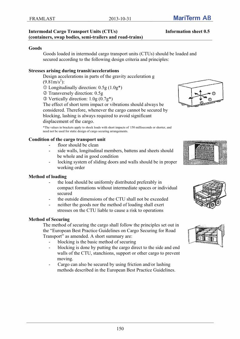
FRAMLAST 2013-10-31
150
Intermodal Cargo Transport Units (CTUs) Information sheet 0.5 (containers, swap bodies, semi-trailers and road-trains)
Goods Goods loaded in intermodal cargo transport units (CTUs) should be loaded and secured according to the following design criteria and principles:
Stresses arising during transit/accelerations
Design accelerations in parts of the gravity acceleration g (9.81m/s2): Longitudinally direction: 0.5g (1.0g*) Transversely direction: 0.5g Vertically direction: 1.0g (0.7g*) The effect of short term impact or vibrations should always be considered. Therefore, whenever the cargo cannot be secured by blocking, lashing is always required to avoid significant displacement of the cargo.
*The values in brackets apply to shock loads with short impacts of 150 milliseconds or shorter, and need not be used for static design of cargo securing arrangements.
Condition of the cargo transport unit - floor should be clean - side walls, longitudinal members, battens and sheets should
be whole and in good condition - locking system of sliding doors and walls should be in proper
working order
Method of loading - the load should be uniformly distributed preferably in
compact formations without intermediate spaces or individual secured
- the outside dimensions of the CTU shall not be exceeded - neither the goods nor the method of loading shall exert
stresses on the CTU liable to cause a risk to operations
Method of Securing The method of securing the cargo shall follow the principles set out in the “European Best Practice Guidelines on Cargo Securing for Road Transport” as amended. A short summary are:
- blocking is the basic method of securing - blocking is done by putting the cargo direct to the side and end
walls of the CTU, stanchions, support or other cargo to prevent moving.
- Cargo can also be secured by using friction and/or lashing methods described in the European Best Practice Guidelines.

FRAMLAST 2013-10-31
151
9.4.2 Dangerous goods on road: EN-12195-1:2010
The standard EN 12195-1:2010 is since the 1st of July 2013 referenced in ADR, the regulation for transport of dangerous goods by road, as sufficient means of cargo securing of dangerous goods. As the RID, regulation for transport of dangerous goods by rail, for combined transports accept cargo prepared for a road transport the standard EN 12195-1:2010 is indirect accept also for a combined transport by rail. If the UIC Loading Guidelines are complemented according to the above proposal it is also recommended to approach CEN/TC 168 to get the basic design accelerations for combined rail transports altered to be in line with the accelerations for road transports. This is important not to jeopardize the future increase of combined rail transports as the cargo securing standard EN 12195-1:2010 might be used to form the bases for a future cargo securing directive within the European Community.
9.4.3 Road: European Best Practice Guidelines
The European Best Practice Guidelines – Cargo securing for road transport (2006) is at the moment under revision (July 2013) with the goal that the Guidelines shall follow the dimensioning criteria and the securing methods described in the standard EN-12195-1:2010. The amendment is planned to be ready during this year 2013.
9.4.4 Sea: IMO/ILO/UNECE Guidelines for packing of CTUs
Also the IMO/ILO/UNECE Guidelines for packing of CTUs is under revision and will be transformed to a Code of Practice, the “CTU Code”, and the dimensioning criteria are established for all modes of transport. The proposal of acceleration factors for Rail (combined transport) is:
Rail transport (combined transport)
Securing in
Acceleration coefficients Longitudinally (cx) Transversely
(cy) Minimum vertically down
(cz) forward rearward
Longitudinal direction 0.5 (1.0)† 0.5 (1.0)† - 1.0 (0.7)†
Transverse direction - - 0.5 1.0† † The values in brackets apply to shock loads with short impacts of 150 milliseconds or
shorter, and need not be used for static design of cargo securing arrangements.
The CTU Code is planned to be established the first half of 2014. If these proposals for the different modes of transport, with a common view on dimensioning criteria and method of securing, will be established it would be a favorable situation for intermodal transports.
FRAMLAST 2013-10-31
152
10. CONCLUSIONS AND RECOMMENDATIONS Within the FRAMLAST project the following have been studied and tested:
Regulations and standards for cargo securing equipment Results and experiences from earlier projects Mapping of current parameters for trailers, containers, swap bodies and flat racks Field studies and visits in ports Extensive container tests Examination in form of a questionnaire of demands and requirements of future CTUs Expected development in medium term (20 years) of CTUs in the European traffic Proposal of revision of standards Requirements for cargo securing in intermodal transport
10.1 Expected future CTU
The conclusion of the work within this project is that the “standard” trailer in medium term, within the next 20 years, will be 13.6 m long and have an inside width and height of about 2.48 m and 2.70 m respectively. Some changes may be made of the height but the maximum permissible vehicle height in many European countries of 4 m is limiting the development of higher units. With very special low profile tires increased vehicle inside heights up to 3 m can be reached, but this will not be commonly available. The trailers will be of curtainsider type and will be built according the standard EN 12642 XL with strong headboard, rear wall and sides. According to the major trailer manufacturers in Europe 99 % of all manufactured curtainsiders and box trailers are XL-trailers since around 2009. The average lifetime of a trailer is 12 years and it is thus estimated that the majority of all trailers is XL-trailers in 2020 on the North West European market. Regarding containers used in the European traffic, the development is moving towards pallet wide continental containers, or rather 45’ PWHC - pallet wide high cube containers, which is driven forward by shipping lines with container feeder ships. These pallet wide containers are adequate for shipping euro-pallets and can be handled, stacked and in general shipped more easily than semi-trailers. What speaks against 45 'PWHC containers is that the payload is less in a container in comparison with in a trailer, that loading is not possible from the side as well as the tough competition for the container traffic against the cheap trailer transports. The prospects for container traffic would be improved by a change in the regulatory environment for higher gross weight of the transport of 45’ containers, the same as for 40’ containers. The inside height of a high cube container is about 2695 mm instead of about 2385 mm as in a standard container. For information it should be mentioned that almost all new standard 40’ maritime containers are high cube containers. The summary of the results of the work in the FRAMLAST project is that the XL-classed 13.6 m curtain sided trailer and the pallet wide 45’ high cube (PWHC) container will dominate the market within the 20 coming years, see the approximate dimensions below. The market for hybrid units like the TELLIBOX and CUSI is supposed to be limited. It is a great wish that new allowed combinations are built up around existing standard modules not to

FRAMLAST 2013-10-31
153
jeopardize the development of intermodal traffic. For specific flows however other vehicle length, width and height may be considered.
13.6 m curtainsided XL-trailer 45’ PWHC container
Curtain sided
XL-trailer 45’ PWHC
continental containerStandard 40’ maritime
container
Internal length (m) 13.6 13.55 12.029
Internal width (m) 2.48 2.43 2.35
Internal height (m) 2.70 – 2.75 2.69 2.385
Volume (m3) 91 89.1 67.7
Payload (kg) 26 150 – 28 750 29 550* 26 700*
Tare (kg) 6 250 – 6 600 4 450* 3 780*
*) A container chassi, with an approximate weight of 5 ton, must be used for the road transport and has to be added to the gross weight of the equipage. More and more trailers are manufactured with piggy back and ferry outfitting which provides a greater flexibility for the trailer. Sliding roof is standard and 99 % of new trailers in Europe have sliding roof. The last percent is trailers for the UK and trailers with hamburger roof. Even if the roof never will be opened customers want the trailers to be flexible. The roof is possible to open approximate 11.3 m. Side doors are no longer requested, except for some single customers. The number of box trailers, without side doors, is increasing and this because of the increasing risk of theft. The trend regarding anti-theft outfitting is getting more and more important; door locks are covered, the hinged safety lock under the rear door has padlock, electronic lock system via 2-way communication may be used etc. The insurance companies in France require that curtainsiders are made with steel reinforcement not possible to cut up. Lashing bars are standard on new trailers. Normally the strength in each lashing hole is two ton and three holes per meter can simultaneously be used for 2 ton each. A problem is to use horizontal lashings in the continuous lashing bars. Often the lashing bar is complemented
FRAMLAST 2013-10-31
154
with ordinary lashing points that can be used for loop lashings where one hook has to lay flat on the floor. A small percentage of the trailer orders in Europe are equipped with fixed lashings and is often ordered in trailers for rent. The LC in fixed lashings is normally 2.5 tons. Stanchions are not standard but can be ordered as special equipment. Approximate 10 % of the orders of trailers in Europe are equipped with stanchions. Finally it should be mentioned that major improvements in CTUs probably occurs only when the industry requires it in the procurements with forwarders and carriers. This will mean increased initially costs for the transports but if any changes are to take place, the requirements must come from the end users.
10.2 Change of standards
Based on tests and studies made within the FRAMLAST project as well as experience from other research projects carried out within the Sir-C consortium proposals and recommen-dations are given for improvements of different CEN and ISO standards. The proposals should be used as input when the respective standard is being updated the next time. Proposal of major changes are in particular formulated for the EN standards EN 12640 and EN 12642 and the ISO standards ISO 1496-1 for containers and ISO 1496-5 for flat racks. The proposals of changes in EN 12642 are concentrated to the strength of the front wall, the side walls and the floor. Also the requirements for marking signs should be complemented. The EN 12640 is containing requirements for lashing points on road vehicles and proposals of identification, design requirements, number of lashing points, testing directions as well as the marking are made. A specification of lashing bars is proposed to be inserted in the standard. Lashing bars are widely used in Europe but nothing about it is mentioned in the standard. In the ISO-standards 1496-1 and 1496-5 the proposals are concentrated to strength in container walls and ends and securing points. The proposals should be used by SIS as a Swedish proposal on the revision when working groups for the different standards are established. A national German working group has since late 2011 been working on a proposal for a revision of EN 12642. It has not been stated when this proposal will be sent to CEN to get an international working group established.
10.3 Harmonization of requirements for cargo securing on road / rail /sea
The principles for cargo securing in CTUs differs completely between the current rules and regulations for road and sea transports on one hand and rail transports on the other. This is not a favorable circumstance for combined transports.
FRAMLAST 2013-10-31
155
The problem with completely different rules for transport by road and rail brings matter to a head when it comes to curtainsider, especially as the number of curtainsiders (trailers and swap bodies) is steadily increasing. The non XL-classed curtain side is according to the European standard EN 12642 regarded as a weather protection only and is not deemed to be used for cargo securing. Even if the control of observing the international cargo securing regulations on intermodal rail transports is not troublesome at present, it is unsatisfactory that regulations and normal practice differs radically from each other. If an incident or accident would happen in a combined transport train there is an obvious risk that the authorities with immediate effect decide to apply current regulations. In CombiSec tests have been carried out and basic facts have been developed and work to try to get a change of the UIC Loading Guidelines has been going forward in the FRAMLAST project. The CombiSec project resulted in a proposal of changing the design acceleration from 1.0 g to 0.5g in longitudinal direction. This acceleration is set in the draft version of the global CTU Code (the revised IMO/ILO/UNECE Guidelines for Packing of Cargo Transport Units (CTUs)). The draft CTU Code was discussed at meetings in IMO’s subcommittee DSC 18 in London in September 2013 and in UNECE’s working group WP24 in October and further work took place in the UNECE’s expert Group in Geneva in November. No objections to the reduced acceleration value arose from these meetings. Although the work of the expert group is now completed, the code is still not finalized. When all changes in the draft have been inserted, it shall be translated into French and Spanish and sent to the three main agencies IMO, ILO and UNECE for final approval. This will be done in the spring 2014. However, it is very unlikely that there will be changes to the content during this process. This means that we should be able to look forward to a new Code of Practice for cargo securing in CTUs by mid next year. Progress is also being made in the UIC cargo securing committee that has accepted the 0.5 g acceleration value in the CTU Code. An imposition of equivalent requirements in the UIC Loading Guidelines is possible in the future but this only after implementation of further tests and measurements. If the proposal on design accelerations of 0.5 g in transverse as well as in longitudinal direction for combined transports will be established it would be a favorable situation for intermodal transports.
FRAMLAST 2013-10-31
156
APPENDIX - Reports from tests, visits and meetings within the project This appendix contains reports from the tests, visits and meetings within the FRAMLAST project. During the project study visits at the Port of Åhus, Port of Gothenburg, Cronos Containers and Schmitz Cargobull have been carried out. A meeting has been arranged in Helsingborg with representatives from Krone and some important information was found out during a cargo securing training focusing on superstructures. A meeting has also been arranged with Ability Landin AB with participation of Transatlantic by phone. Visits at the fair trades in Munich and Hannover have also been performed. Study visits have also been carried out at Sandvik in Sandviken, Korsnäs in Gävle, GDL in Helsingborg, DHL in Gothenburg and DSV Road in Landskrona, but no reports from these visits are available. Tests have been carried out of the strength in the corrugation of a container as well as in the securing points and in the floor of a container. Contents
A1. Visit in Port of Åhus port
A2. Visit in Port of Gothenburg
A3. Visit at the fair trade Transport logistics in Munich 2011
A4. Questions emerging at cargo securing training
A5. Visit at Cronos in Gothenburg
A6. Container tests in Gothenburg
A7. Visit at Schmitz Cargobull
A8. Meeting with Krone
A9. Visit at the fair trade IAA in Hannover
A10. Meeting with Ability Landin AB and Transatlantic
A11. Visit at the fair trade Transport logistics in Munich 2013

FRAMLAST 2013-10-31
A1. 1
A1. Visit in Port of Åhus
The Port of Åhus was visited on the 18th of April 2011 to study the curtainside containers from Transatlantic.
The curtainside containers from Transatlantic The containers were put in traffic in the summer of 2006 and 100 units were taken in circulation. Today there is about 80 units left and these are sailing in Europe only. The units have two curtain sides and doors at one of the ends. The container has the following dimensions: Outside: Length: 13600 mm Width: 2500 mm Height: 2900 mm Inside: Length: 13450 mm Width: 2430 / 2470 mm Height: 2580 mm Height, sideloading: 2520 mm Cubic: 85 cbm Max brutto weight: 34000 kg Tare: 4970 kg Payload: 29030 kg Advantages with the curtainside container:
The flexibility with loading also from the side The units are circulating in normal container traffic Stackable
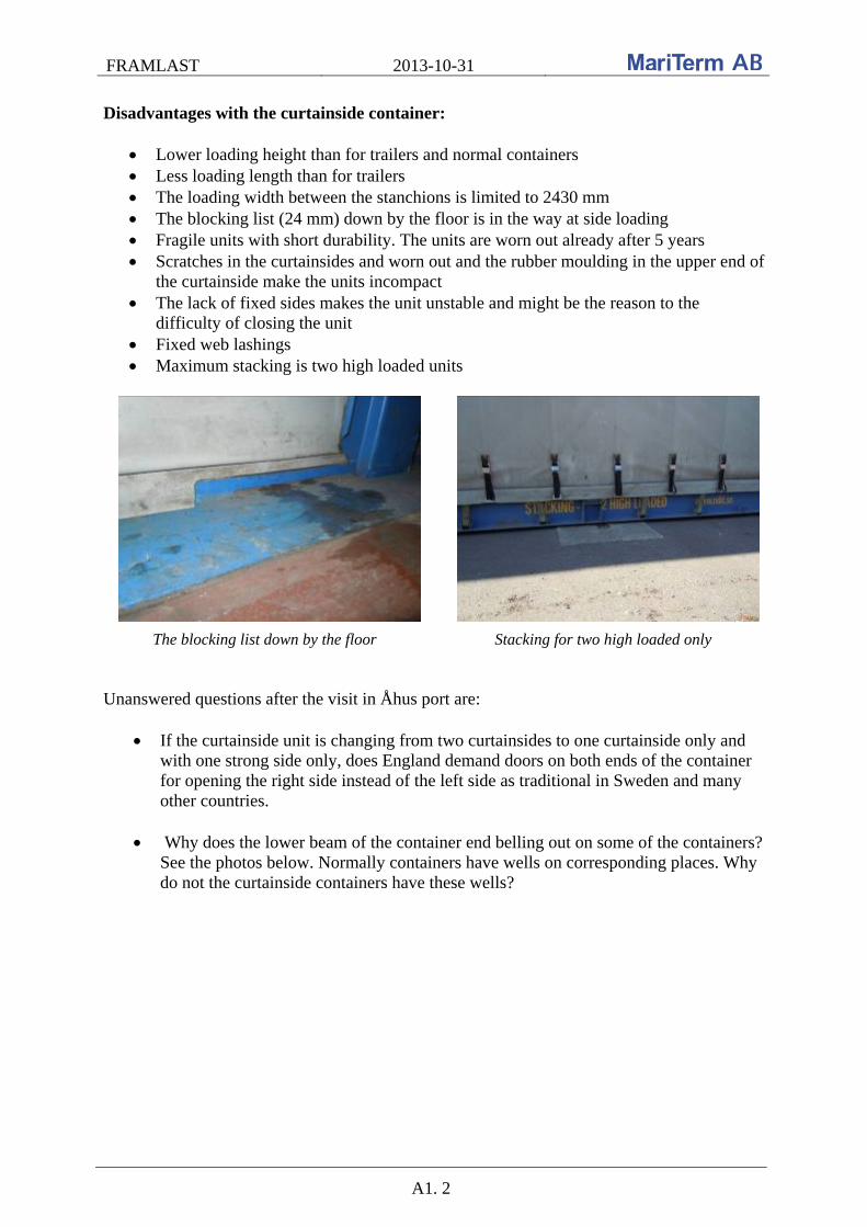
FRAMLAST 2013-10-31
A1. 2
Disadvantages with the curtainside container:
Lower loading height than for trailers and normal containers Less loading length than for trailers The loading width between the stanchions is limited to 2430 mm The blocking list (24 mm) down by the floor is in the way at side loading Fragile units with short durability. The units are worn out already after 5 years Scratches in the curtainsides and worn out and the rubber moulding in the upper end of
the curtainside make the units incompact The lack of fixed sides makes the unit unstable and might be the reason to the
difficulty of closing the unit Fixed web lashings Maximum stacking is two high loaded units
The blocking list down by the floor Stacking for two high loaded only Unanswered questions after the visit in Åhus port are:
If the curtainside unit is changing from two curtainsides to one curtainside only and with one strong side only, does England demand doors on both ends of the container for opening the right side instead of the left side as traditional in Sweden and many other countries.
Why does the lower beam of the container end belling out on some of the containers? See the photos below. Normally containers have wells on corresponding places. Why do not the curtainside containers have these wells?
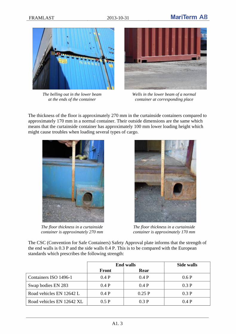
FRAMLAST 2013-10-31
A1. 3
The belling out in the lower beam at the ends of the container
Wells in the lower beam of a normal container at corresponding place
The thickness of the floor is approximately 270 mm in the curtainside containers compared to approximately 170 mm in a normal container. Their outside dimensions are the same which means that the curtainside container has approximately 100 mm lower loading height which might cause troubles when loading several types of cargo.
The floor thickness in a curtainside container is approximately 270 mm
The floor thickness in a curtainside container is approximately 170 mm
The CSC (Convention for Safe Containers) Safety Approval plate informs that the strength of the end walls is 0.3 P and the side walls 0.4 P. This is to be compared with the European standards which prescribes the following strength: End walls Side walls
Front Rear
Containers ISO 1496-1 0.4 P 0.4 P 0.6 P
Swap bodies EN 283 0.4 P 0.4 P 0.3 P
Road vehicles EN 12642 L 0.4 P 0.25 P 0.3 P
Road vehicles EN 12642 XL 0.5 P 0.3 P 0.4 P
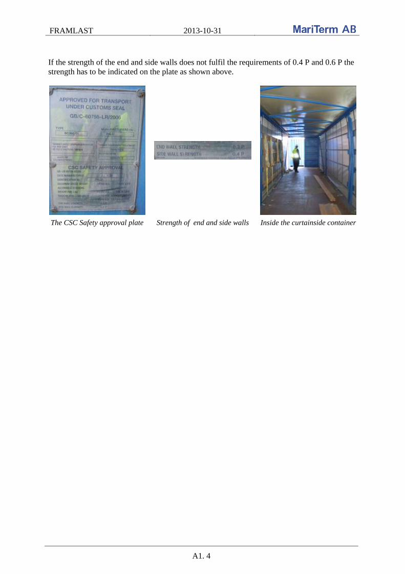
FRAMLAST 2013-10-31
A1. 4
If the strength of the end and side walls does not fulfil the requirements of 0.4 P and 0.6 P the strength has to be indicated on the plate as shown above.
The CSC Safety approval plate Strength of end and side walls Inside the curtainside container
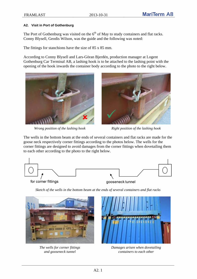
FRAMLAST 2013-10-31
A2. 1
A2. Visit in Port of Gothenburg The Port of Gothenburg was visited on the 6th of May to study containers and flat racks. Conny Blysell, Geodis Wilson, was the guide and the following was noted: The fittings for stanchions have the size of 85 x 85 mm. According to Conny Blysell and Lars-Göran Bjerdén, production manager at Logent Gothenburg Car Terminal AB, a lashing hook is to be attached to the lashing point with the opening of the hook inwards the container body according to the photo to the right below.
Wrong position of the lashing hook Right position of the lashing hook The wells in the bottom beam at the ends of several containers and flat racks are made for the goose neck respectively corner fittings according to the photos below. The wells for the corner fittings are designed to avoid damages from the corner fittings when dovetailing them to each other according to the photo to the right below.
Sketch of the wells in the bottom beam at the ends of several containers and flat racks
The wells for corner fittings and gooseneck tunnel
Damages arisen when dovetailing containers to each other

FRAMLAST 2013-10-31
A2. 2
The rolltrailers from Cronos are equipped with lashing lines. This solution of lashing points should also be available on flat racks.
Lashing line on the rolltrailers from Cronos During the visit in the port the position of lashing points were studied. Photos of accurate as well as bad positioning of lashing points are shown below.
There might be a risk of over width flat racks with these type of lashing points
Better positioning of lashing points
Ok positioning of lashing points
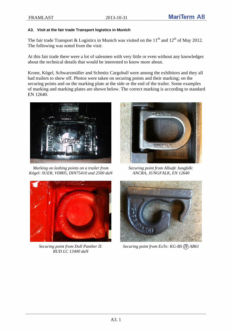
FRAMLAST 2013-10-31
A3. 1
A3. Visit at the fair trade Transport logistics in Munich The fair trade Transport & Logistics in Munich was visited on the 11th and 12th of May 2012. The following was noted from the visit: At this fair trade there were a lot of salesmen with very little or even without any knowledges about the technical details that would be interested to know more about. Krone, Kögel, Schwarzmüller and Schmitz Cargobull were among the exhibitors and they all had trailers to show off. Photos were taken on securing points and their marking; on the securing points and on the marking plate at the side or the end of the trailer. Some examples of marking and marking plates are shown below. The correct marking is according to standard EN 12640.
Marking on lashing points on a trailer from Kögel: SUER, VD805, DIN75410 and 2500 daN
Securing point from Allsafe Jungfalk: ANCRA, JUNGFALK, EN 12640
Securing point from Doll Panther II: RUD LC 13400 daN
Securing point from ExTe: KG-BS H AB61

FRAMLAST 2013-10-31
A3. 2
Securing point from Faymonville I: EN 12640-100, LC 10.000 daN
Marking of securing point: LC 8000 daN
The marking plates on trailers from Kögel and Schwarzmüller
The marking plates on trailers from Schmitz Cargobull and Schwarzmüller Questions were asked about the deflection of XL-sides but references were left to Thorsten Perk at Krone and to other technical departments on the other companies to get detailed
FRAMLAST 2013-10-31
A3. 3
information about this. Mr Perk was contacted and his answer was very brief. A new mail is sent to him with a proposal to attend to the next tests of the XL-sides. No answer is received. Cronos was visited with hope to get Jan Hellström, Cronos representative in Sweden, involved in the project. Juraj Jagelcak from Zilina University will be joining the next meeting of Framlast and he will then present his container inspection project. Unit 45 showed their new Wing unit; a 45’ unit with walls of composite material designed to withstand 1.2 times the cargo weight. Tests of the strength of the sides will be performed at the 31st of October and the results will be available after that.

FRAMLAST 2013-10-31
A4. 1
A4. Questions emerging at cargo securing training
At a cargo securing training in Gothenburg on the 26th of May the following questions emerged:
In future Swedish regulations it should be prescribed that cargo transported in containers and trailers with box type bodies must be secured so that the cargo do not fall out when the doors are opened
In future regulations it should also be prescribed that containers must be transported with the doors in rear direction.
The strength of side walls in containers is designed to withstand a load of 0.6 times
the maximum permissible payload, 0.6 P. This are prescribed in the container ISO standard ISO 1496-1. If the strength is less or greater than this the strength factor shall be indicated on the Safety Approval Plate.
Marking of web, chain and wire lashings according to the standards EN 12195-2 -- 4
is not a directive in Sweden.
Marking of the pre tension STF should be on the ratchet only and not the web lashing
An ISO-standard is a global concern. Is it the same principles for EN and ISO standards? The EN standards are not a directive until national regulations say that it is
The force when testing the strength of side walls in XL-units shall be applied
uniformly up to ¾ height of the body structure. Why is 75 % of side tested only?
There should be more harmony between the standards EN 12195-2 -- 4 and EN 12640
What does tensile load mean in the standards? The definition is missing
According to EN 12195-2 lashings are to be marked with the manufacturer´s or supplier´s name or symbol.

FRAMLAST 2013-10-31
A5. 1
A5. Visit at Cronos in Gothenburg
Cronos office in Gothenburg was visited on the 13th of June. Cronos design, build and rent containers, flat racks, tanks, rolltrailers etc, particularly to shipping companies with approximately 1 million TEU in circulation. The meeting was with Jan Hellström and Christian Balazs. They were informed about the Transatlantic’s and Unit 45’s containers with curtain respectively composite sides. Cronos has never designed anything else than normal containers. The arguments are that containers with curtainsides are more expensive to build, broke more easily and have no second-hand market. Today Cronos is able to sell their 20 years old containers to the same price as they were built or bought for. The curtainside units and units with technical/mechanical solutions sent all over the world are fiddled and screwed of all people and it is no wonder how the units break. Curtainside containers must have an extremely strong bottom construction which ties both the loading height as well as the tare weight. Instead of putting money on new container solutions Cronos has invested in building ramps for loading through the doors of the container. Jan mention the importance in keeping the tare weight down. Many customers choose container after the weight only. Jan Hellström does not believe in having one fixed side and one curtain side. If one side is possible to open the other may be that as well. Jan also says that the curtainside containers do not fit onboard vessels because of the limit of stacking two loaded high only. Several of the details on containers and flat racks are designed by Clyde Smith. Many customers are requesting his design and that is the reason why a number of less good details are on new designed containers and flat racks. This might be the reason why the lashing points are located too far out on the sides so that the flat rack might become over wide. According to the container standard the anchor points, located in the base structure of the container, and the lasing points, located all other parts of the container, shall be designed and installed to provide a minimum rated load of 1000 kg respectively 500 kg in any direction. Corresponding anchor and lashing points on flat racks shall provide a minimum load of 3000 kg respectively 1000 kg. This is far too weak for transporting heavy cargo all around the world. The restriction of the strength in securing points is the construction of the roof; it will be deformed if exposed to higher forces, and the at the floor it is partly lack of space and partly hard to get the welding to manage to keep the lashing ring fixed to the floor. Jan promised to examine the possibility of getting the securing points in the container floor to withstand a load of 2000 kg. The most frequently strength in securing points on flat racks is 5 ton. This might be discretion from the suppliers, they should be able to withstand greater forces. The strength in the lashing lines on rolltrailers from Cronos are 5 ton only. During the tests the lashing line were tested to up to 25 ton but the lashing capacity is put to 5 ton only because of there was some of the test where the line broke at 18 ton only. In precaution the lashing capacity were set to 5 ton.
FRAMLAST 2013-10-31
A5. 2
There are flat racks with lashing lines from Cronos available at the market but not on the Clyde Smith flat racks. Other securing points have managed to withstand 36 ton but the pulling strength were put to 10 ton only. Jan Hellström is translating the pulling strength to lashing capacity in pulling. The goose-neck tunnel is regulated in the container standard but not the wells to match the corner fittings. It was stated that Ro-Ro International has developed hooks which will be at the bottom in securing points with larger dimension of the rod diameter. Why is lashing to the stake pocket bars prohibited? Jan thought that the edge around the stake pocket bars is not as strong as the edge on the places of the flat rack. There should be regulations about rod diameter, location and strength of the securing points in the standards. The dimension of hooks to fit in the securing points should also be regulated. The cargo transport units in the future are believed to be containers and curtainsider trailers.
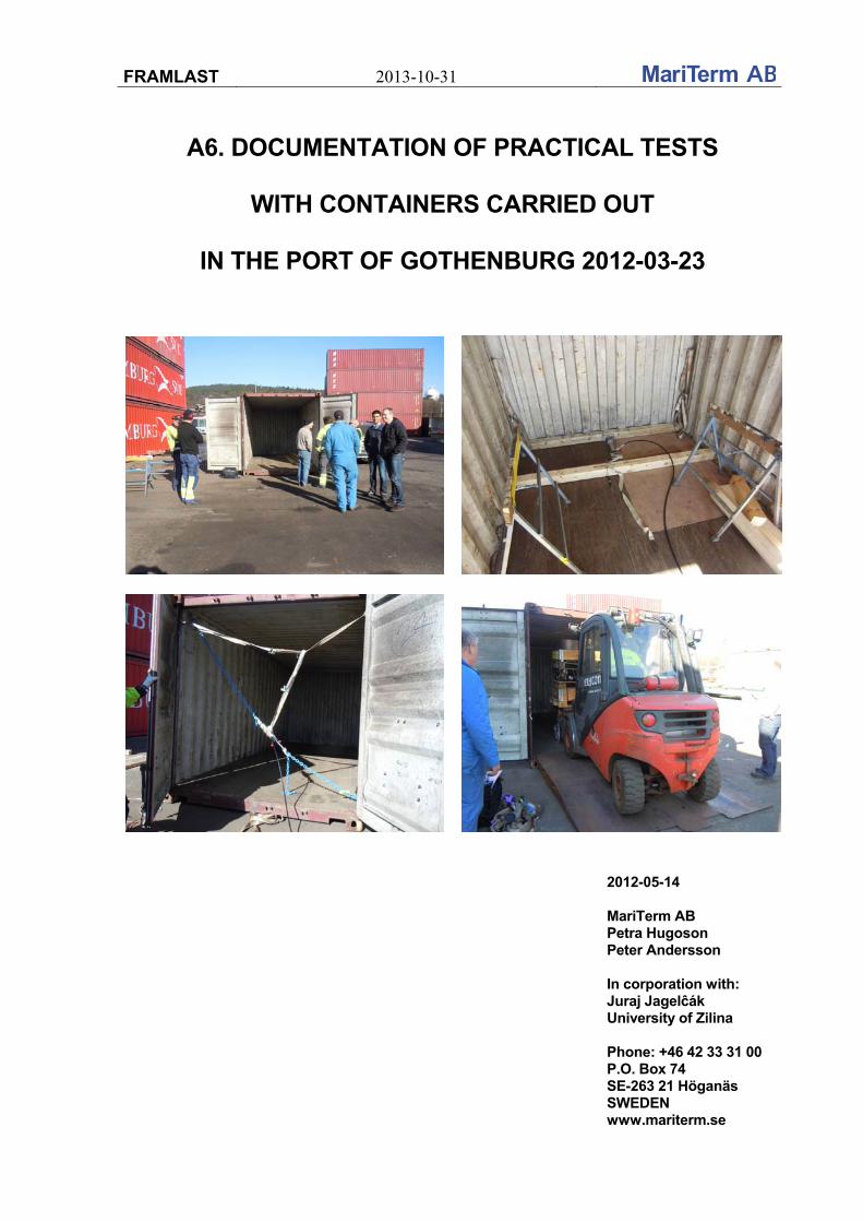
FRAMLAST 2013-10-31
A6. DOCUMENTATION OF PRACTICAL TESTS
WITH CONTAINERS CARRIED OUT
IN THE PORT OF GOTHENBURG 2012-03-23
2012-05-14 MariTerm AB Petra Hugoson Peter Andersson In corporation with: Juraj Jagelĉák University of Zilina Phone: +46 42 33 31 00 P.O. Box 74 SE-263 21 Höganäs SWEDEN www.mariterm.se
FRAMLAST 2013-10-31
A6. 2
TABLE OF CONTENTS
Page
1. INTRODUCTION .................................................................................................. 3
2. TEST EQUIPMENT .............................................................................................. 4
3. TESTS CARRIED OUT ........................................................................................ 7
3.1 Strength in the corrugation ........................................................................ 7
3.2 Strength in securing points ..................................................................... 11
3.3 Strength in the floor .................................................................................. 19
4. SUMMERY AND CONCLUSIONS ..................................................................... 23
ANNEX 1 – CONTAINER SPECIFICATION - CRONOS .......................................... 26
FRAMLAST 2013-10-31
A6. 3
1. INTRODUCTION Within the research project FRAMLAST – Development of Intermodal Transport Units -MariTerm AB in cooperation with University of Zilina have led and documented container tests carried out at Elfcon container service AB in the Port of Gothenburg on the 23rd of March 2012. The tests were carried out in a container from Cronos and consisted of testing the strength in the corrugation, in the lashing points and in the floor of the container. The weather during the tests was sunny and the temperature was about +10 degrees. The following persons were attending the tests: Cronos Container Scandinavia AB Jan Hellström DHL Olle Bernstaf Elfcon container service AB Dennis Salama Forankra ABT Erik Eklöv
Levent Duran Urban Jönsson
Geodis Wilson Conny Blysell MariTerm AB Peter Andersson
Petra Hugoson Volvo Logistics Johan Orte Nelo Nell University of Zilina Juraj Jagelĉák

FRAMLAST 2013-10-31
A6. 4
2. TEST EQUIPMENT Cronos Container Scandinavia put a 20’ dry container for disposal for the tests. The type and number of the container was 22G1 and CRXU 30 71 69-1 with dimensions according to below. Container dimensions: Internal length: 5898 mm
Internal width: 2352 mm
Internal height: 2393 mm
Max payload weight: 28230 kg
Tare weight: 2250 kg The container was manufactured and put in service in June 2004.
The container used in the tests.
The type and number of the container.
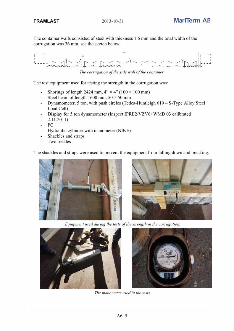
FRAMLAST 2013-10-31
A6. 5
The container walls consisted of steel with thickness 1.6 mm and the total width of the corrugation was 36 mm, see the sketch below.
The corrugation of the side wall of the container The test equipment used for testing the strength in the corrugation was:
- Shorings of length 2424 mm, 4” × 4” (100 × 100 mm) - Steel beam of length 1600 mm, 50 × 50 mm - Dynamometer, 5 ton, with push circles (Tedea-Huntleigh 619 – S-Type Alloy Steel
Load Cell) - Display for 5 ton dynamometer (Inspect IPRE2/VZV6+WMD 03 calibrated
2.11.2011) - PC - Hydraulic cylinder with manometer (NIKE) - Shackles and straps - Two trestles
The shackles and straps were used to prevent the equipment from falling down and breaking.
Equipment used during the tests of the strength in the corrugation.
The manometer used in the tests.

FRAMLAST 2013-10-31
A6. 6
The shorings were made of spruce and the humidity in the timber was measured to be 12 % and the temperature 16.5°C. The device used for this measurement was a Greisinger GMH 3850.
Device to measure the humidity and temperature in the timber. For the tests of the strength in the lashing points the following equipment was used:
- Two chain lashings with hooks - Dynamometer, 5 ton, with screw eyes (Tedea-Huntleigh 619 – S-Type Alloy Steel
Load Cell) - Display for 5 ton dynamometer (Inspect IPRE2/VZV6+WMD 03 calibrated
2.11.2011) - PC - Hydraulic cylinder with manometer (NIKE) - Shackles and straps
The shackles and straps were used to prevent the equipment from falling down and breaking.
Equipment used during the tests of the strength in the lashing points
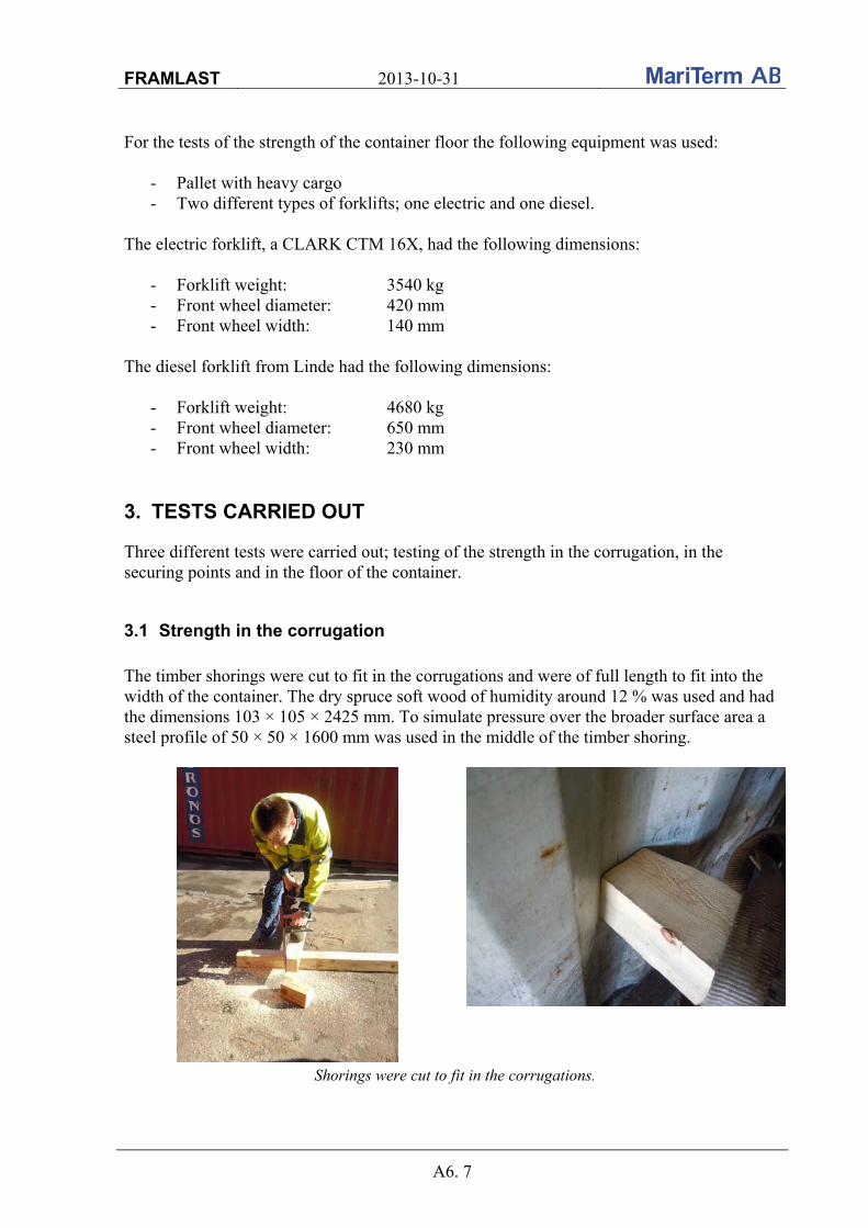
FRAMLAST 2013-10-31
A6. 7
For the tests of the strength of the container floor the following equipment was used:
- Pallet with heavy cargo - Two different types of forklifts; one electric and one diesel.
The electric forklift, a CLARK CTM 16X, had the following dimensions:
- Forklift weight: 3540 kg - Front wheel diameter: 420 mm - Front wheel width: 140 mm
The diesel forklift from Linde had the following dimensions:
- Forklift weight: 4680 kg - Front wheel diameter: 650 mm - Front wheel width: 230 mm
3. TESTS CARRIED OUT
Three different tests were carried out; testing of the strength in the corrugation, in the securing points and in the floor of the container.
3.1 Strength in the corrugation
The timber shorings were cut to fit in the corrugations and were of full length to fit into the width of the container. The dry spruce soft wood of humidity around 12 % was used and had the dimensions 103 × 105 × 2425 mm. To simulate pressure over the broader surface area a steel profile of 50 × 50 × 1600 mm was used in the middle of the timber shoring.
Shorings were cut to fit in the corrugations.
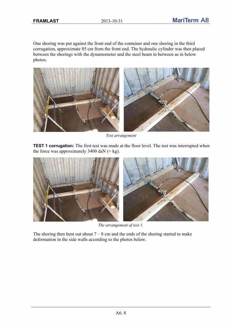
FRAMLAST 2013-10-31
A6. 8
One shoring was put against the front end of the container and one shoring in the third corrugation, approximate 85 cm from the front end. The hydraulic cylinder was then placed between the shorings with the dynamometer and the steel beam in between as in below photos.
Test arrangement TEST 1 corrugation: The first test was made at the floor level. The test was interrupted when the force was approximately 3400 daN (≈ kg).
The arrangement of test 1.
The shoring then bent out about 7 – 8 cm and the ends of the shoring started to make deformation in the side walls according to the photos below.
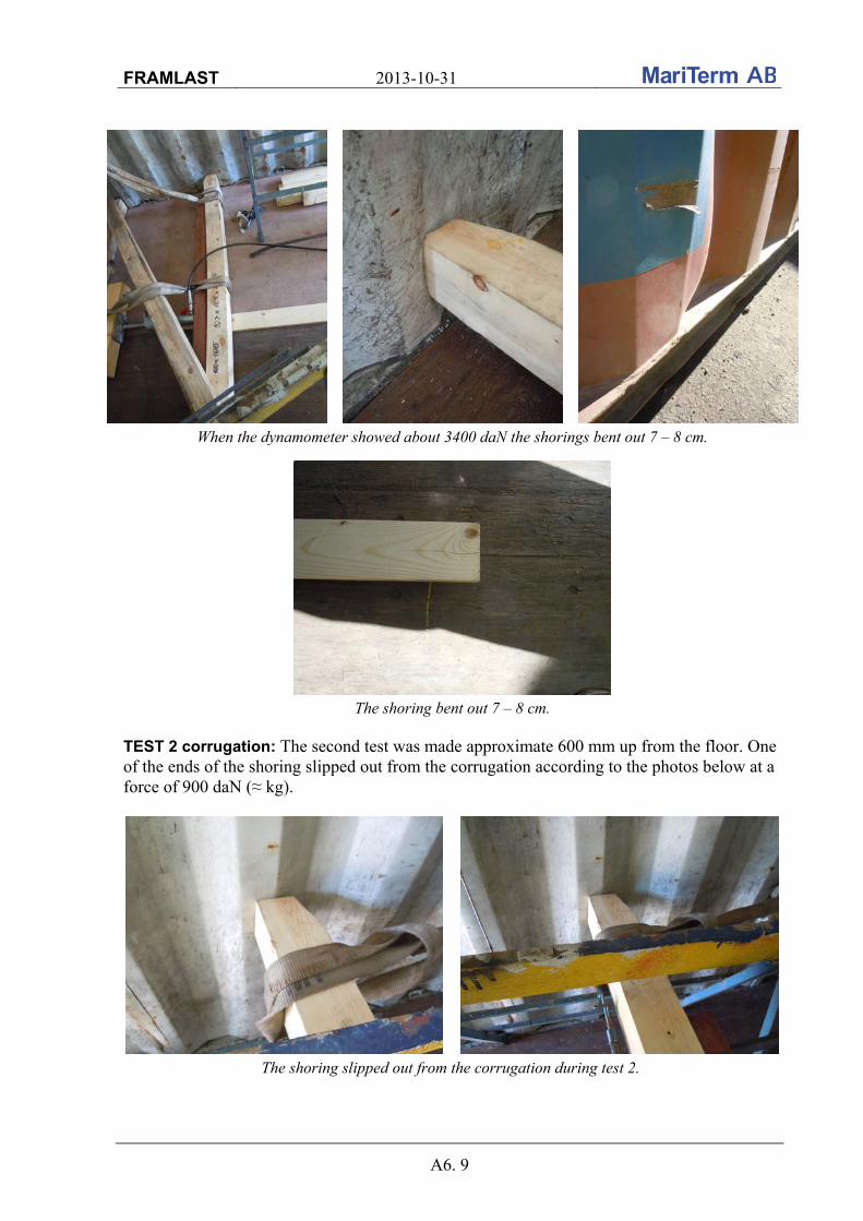
FRAMLAST 2013-10-31
A6. 9
When the dynamometer showed about 3400 daN the shorings bent out 7 – 8 cm.
The shoring bent out 7 – 8 cm. TEST 2 corrugation: The second test was made approximate 600 mm up from the floor. One of the ends of the shoring slipped out from the corrugation according to the photos below at a force of 900 daN (≈ kg).
The shoring slipped out from the corrugation during test 2.
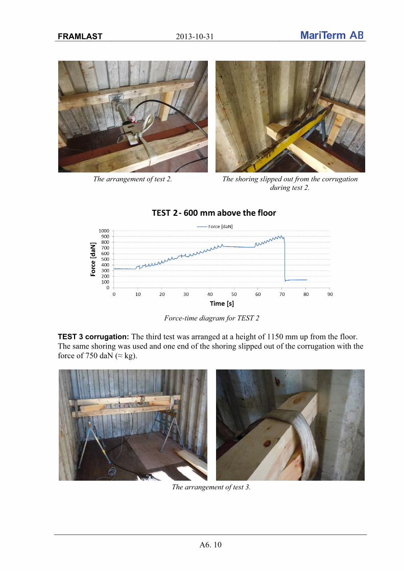
FRAMLAST 2013-10-31
A6. 10
The arrangement of test 2. The shoring slipped out from the corrugation during test 2.
Force-time diagram for TEST 2
TEST 3 corrugation: The third test was arranged at a height of 1150 mm up from the floor. The same shoring was used and one end of the shoring slipped out of the corrugation with the force of 750 daN (≈ kg).
The arrangement of test 3.
2
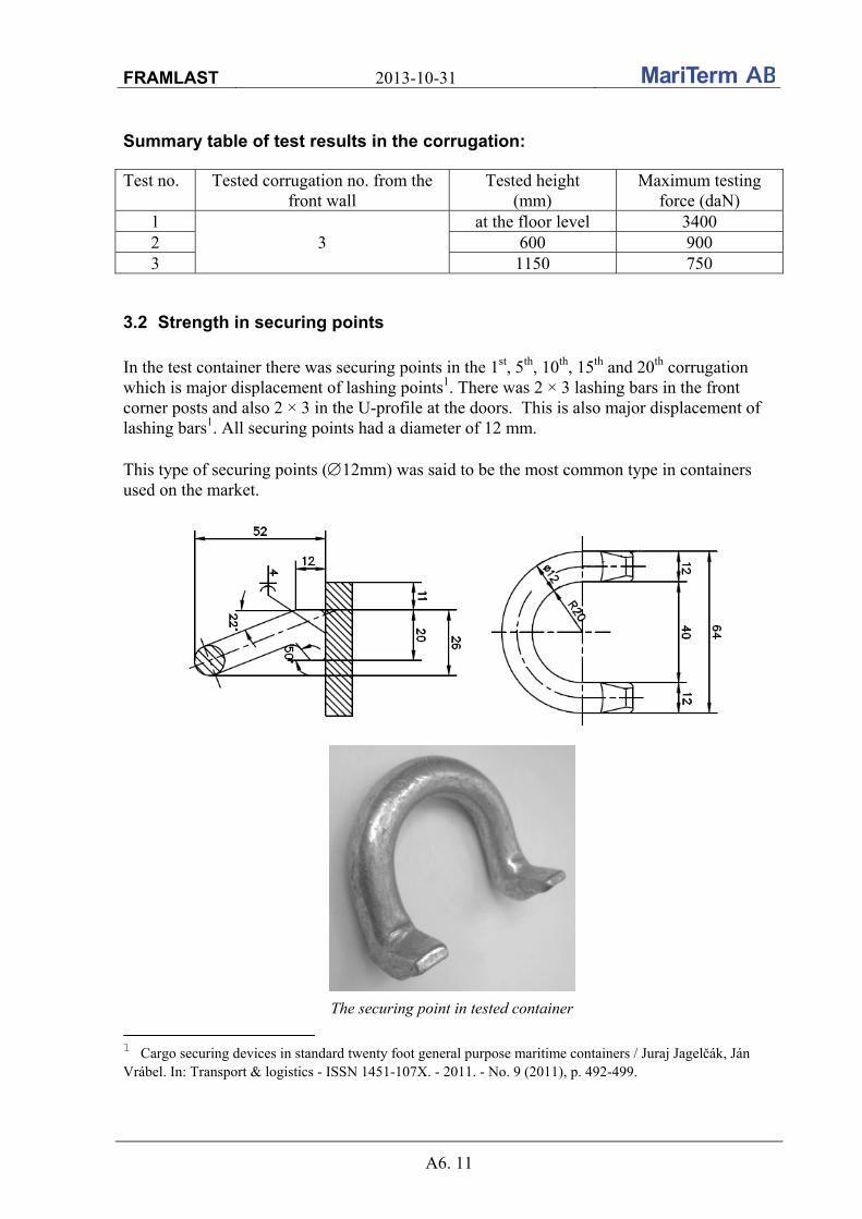
FRAMLAST 2013-10-31
A6. 11
Summary table of test results in the corrugation:
Test no. Tested corrugation no. from the front wall
Tested height (mm)
Maximum testing force (daN)
1 3
at the floor level 3400 2 600 900 3 1150 750
3.2 Strength in securing points
In the test container there was securing points in the 1st, 5th, 10th, 15th and 20th corrugation which is major displacement of lashing points1. There was 2 × 3 lashing bars in the front corner posts and also 2 × 3 in the U-profile at the doors. This is also major displacement of lashing bars1. All securing points had a diameter of 12 mm. This type of securing points (12mm) was said to be the most common type in containers used on the market.
The securing point in tested container
1 Cargo securing devices in standard twenty foot general purpose maritime containers / Juraj Jagelčák, Ján Vrábel. In: Transport & logistics - ISSN 1451-107X. - 2011. - No. 9 (2011), p. 492-499.
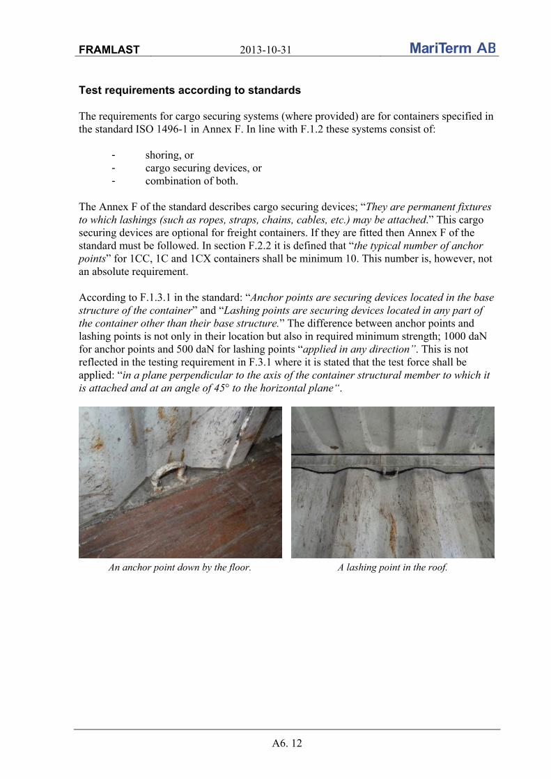
FRAMLAST 2013-10-31
A6. 12
Test requirements according to standards The requirements for cargo securing systems (where provided) are for containers specified in the standard ISO 1496-1 in Annex F. In line with F.1.2 these systems consist of:
- shoring, or - cargo securing devices, or - combination of both.
The Annex F of the standard describes cargo securing devices; “They are permanent fixtures to which lashings (such as ropes, straps, chains, cables, etc.) may be attached.” This cargo securing devices are optional for freight containers. If they are fitted then Annex F of the standard must be followed. In section F.2.2 it is defined that “the typical number of anchor points” for 1CC, 1C and 1CX containers shall be minimum 10. This number is, however, not an absolute requirement. According to F.1.3.1 in the standard: “Anchor points are securing devices located in the base structure of the container” and “Lashing points are securing devices located in any part of the container other than their base structure.” The difference between anchor points and lashing points is not only in their location but also in required minimum strength; 1000 daN for anchor points and 500 daN for lashing points “applied in any direction”. This is not reflected in the testing requirement in F.3.1 where it is stated that the test force shall be applied: “in a plane perpendicular to the axis of the container structural member to which it is attached and at an angle of 45° to the horizontal plane“.
An anchor point down by the floor. A lashing point in the roof.
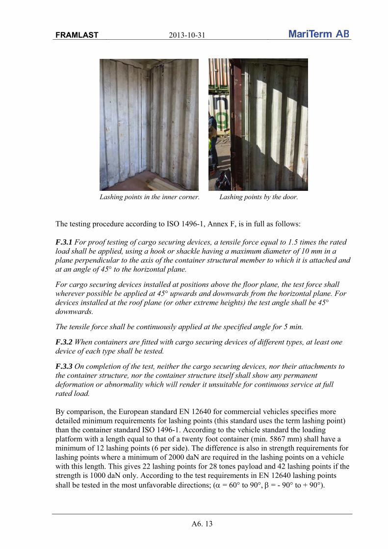
FRAMLAST 2013-10-31
A6. 13
Lashing points in the inner corner. Lashing points by the door. The testing procedure according to ISO 1496-1, Annex F, is in full as follows: F.3.1 For proof testing of cargo securing devices, a tensile force equal to 1.5 times the rated load shall be applied, using a hook or shackle having a maximum diameter of 10 mm in a plane perpendicular to the axis of the container structural member to which it is attached and at an angle of 45° to the horizontal plane.
For cargo securing devices installed at positions above the floor plane, the test force shall wherever possible be applied at 45° upwards and downwards from the horizontal plane. For devices installed at the roof plane (or other extreme heights) the test angle shall be 45° downwards.
The tensile force shall be continuously applied at the specified angle for 5 min.
F.3.2 When containers are fitted with cargo securing devices of different types, at least one device of each type shall be tested.
F.3.3 On completion of the test, neither the cargo securing devices, nor their attachments to the container structure, nor the container structure itself shall show any permanent deformation or abnormality which will render it unsuitable for continuous service at full rated load. By comparison, the European standard EN 12640 for commercial vehicles specifies more detailed minimum requirements for lashing points (this standard uses the term lashing point) than the container standard ISO 1496-1. According to the vehicle standard the loading platform with a length equal to that of a twenty foot container (min. 5867 mm) shall have a minimum of 12 lashing points (6 per side). The difference is also in strength requirements for lashing points where a minimum of 2000 daN are required in the lashing points on a vehicle with this length. This gives 22 lashing points for 28 tones payload and 42 lashing points if the strength is 1000 daN only. According to the test requirements in EN 12640 lashing points shall be tested in the most unfavorable directions; ( = 60° to 90°, = - 90° to + 90°).

FRAMLAST 2013-10-31
A6. 14
Results of the tests of anchor and lashing points The tests were carried out with two chain lashings in two different securing points with the hydraulic cylinder in between. The hydraulic pressure was read on the manometer and the corresponding tensile force was read in the tables and diagram below as well as on the PC dynamometer.
The relation between the hydraulic pressure and the force. The cargo securing devices were tested not only in a plane perpendicular to the axis of the container but also for different lashing angles β. The dynamometer was not used in the first three tests of the strength in the securing points. TEST 1 securing points: The first test was carried out between two securing points just inside the container doors in the 20th corrugation; the anchor point to the right down by the floor (20RD) and the lashing point to the left in the roof (20LU). The test equipment was attached at an angle of 43.5° to the horizontal plane.
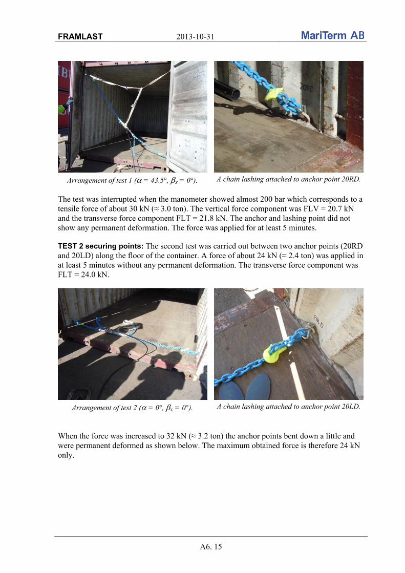
FRAMLAST 2013-10-31
A6. 15
Arrangement of test 1 ( = 43.5°, x = 0°). A chain lashing attached to anchor point 20RD.
The test was interrupted when the manometer showed almost 200 bar which corresponds to a tensile force of about 30 kN (≈ 3.0 ton). The vertical force component was FLV = 20.7 kN and the transverse force component FLT = 21.8 kN. The anchor and lashing point did not show any permanent deformation. The force was applied for at least 5 minutes. TEST 2 securing points: The second test was carried out between two anchor points (20RD and 20LD) along the floor of the container. A force of about 24 kN (≈ 2.4 ton) was applied in at least 5 minutes without any permanent deformation. The transverse force component was FLT = 24.0 kN.
Arrangement of test 2 ( = 0°, x = 0°). A chain lashing attached to anchor point 20LD.
When the force was increased to 32 kN (≈ 3.2 ton) the anchor points bent down a little and were permanent deformed as shown below. The maximum obtained force is therefore 24 kN only.
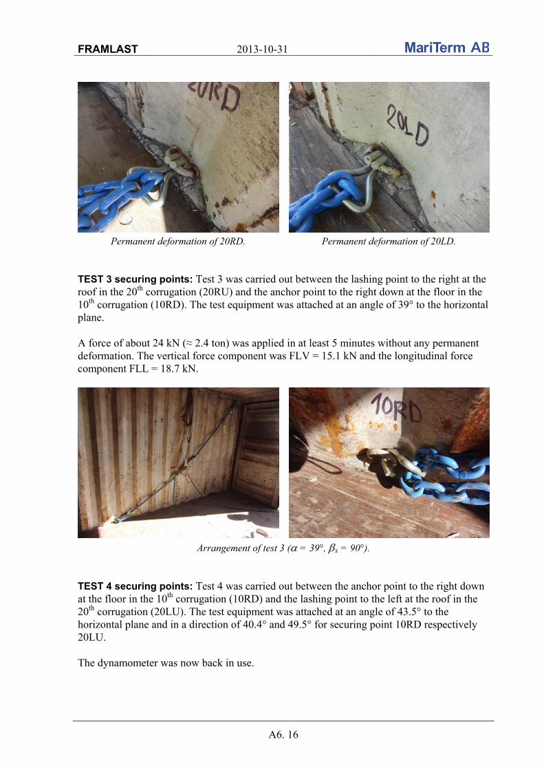
FRAMLAST 2013-10-31
A6. 16
Permanent deformation of 20RD. Permanent deformation of 20LD. TEST 3 securing points: Test 3 was carried out between the lashing point to the right at the roof in the 20th corrugation (20RU) and the anchor point to the right down at the floor in the 10th corrugation (10RD). The test equipment was attached at an angle of 39° to the horizontal plane. A force of about 24 kN (≈ 2.4 ton) was applied in at least 5 minutes without any permanent deformation. The vertical force component was FLV = 15.1 kN and the longitudinal force component FLL = 18.7 kN.
Arrangement of test 3 ( = 39°, x = 90°). TEST 4 securing points: Test 4 was carried out between the anchor point to the right down at the floor in the 10th corrugation (10RD) and the lashing point to the left at the roof in the 20th corrugation (20LU). The test equipment was attached at an angle of 43.5° to the horizontal plane and in a direction of 40.4° and 49.5° for securing point 10RD respectively 20LU. The dynamometer was now back in use.
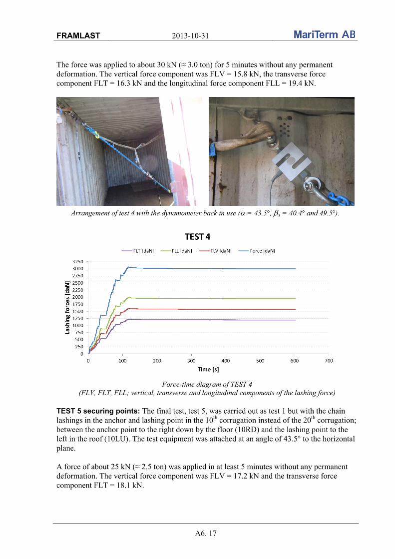
FRAMLAST 2013-10-31
A6. 17
The force was applied to about 30 kN (≈ 3.0 ton) for 5 minutes without any permanent deformation. The vertical force component was FLV = 15.8 kN, the transverse force component FLT = 16.3 kN and the longitudinal force component FLL = 19.4 kN.
Arrangement of test 4 with the dynamometer back in use ( = 43.5°, x = 40.4° and 49.5°).
Force-time diagram of TEST 4
(FLV, FLT, FLL; vertical, transverse and longitudinal components of the lashing force) TEST 5 securing points: The final test, test 5, was carried out as test 1 but with the chain lashings in the anchor and lashing point in the 10th corrugation instead of the 20th corrugation; between the anchor point to the right down by the floor (10RD) and the lashing point to the left in the roof (10LU). The test equipment was attached at an angle of 43.5° to the horizontal plane. A force of about 25 kN (≈ 2.5 ton) was applied in at least 5 minutes without any permanent deformation. The vertical force component was FLV = 17.2 kN and the transverse force component FLT = 18.1 kN.
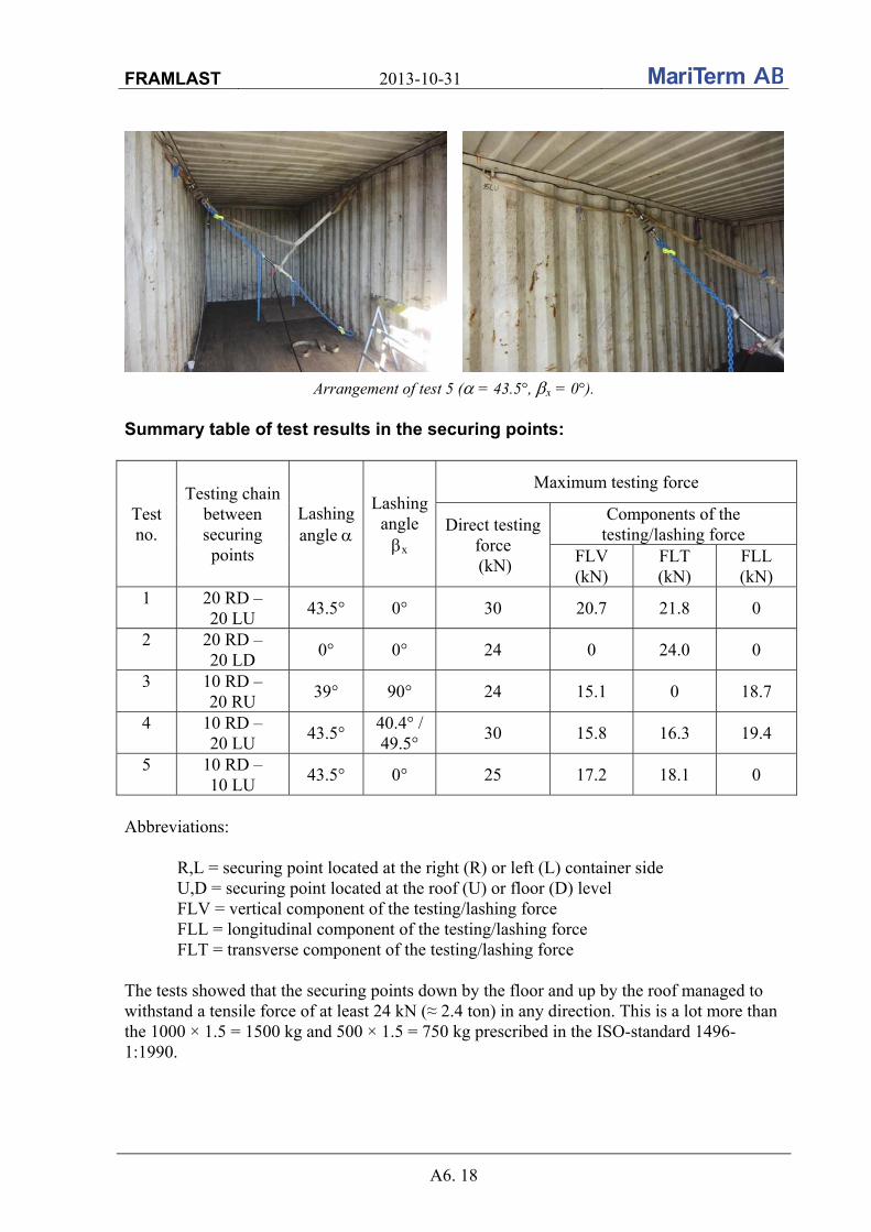
FRAMLAST 2013-10-31
A6. 18
Arrangement of test 5 ( = 43.5°, x = 0°). Summary table of test results in the securing points:
Test no.
Testing chain between securing points
Lashing angle
Lashing angle x
Maximum testing force
Direct testing force (kN)
Components of the testing/lashing force
FLV (kN)
FLT (kN)
FLL (kN)
1 20 RD – 20 LU
43.5° 0° 30 20.7 21.8 0
2 20 RD – 20 LD
0° 0° 24 0 24.0 0
3 10 RD – 20 RU
39° 90° 24 15.1 0 18.7
4 10 RD – 20 LU
43.5° 40.4° / 49.5°
30 15.8 16.3 19.4
5 10 RD – 10 LU
43.5° 0° 25 17.2 18.1 0
Abbreviations: R,L = securing point located at the right (R) or left (L) container side U,D = securing point located at the roof (U) or floor (D) level FLV = vertical component of the testing/lashing force
FLL = longitudinal component of the testing/lashing force FLT = transverse component of the testing/lashing force
The tests showed that the securing points down by the floor and up by the roof managed to withstand a tensile force of at least 24 kN (≈ 2.4 ton) in any direction. This is a lot more than the 1000 × 1.5 = 1500 kg and 500 × 1.5 = 750 kg prescribed in the ISO-standard 1496-1:1990.
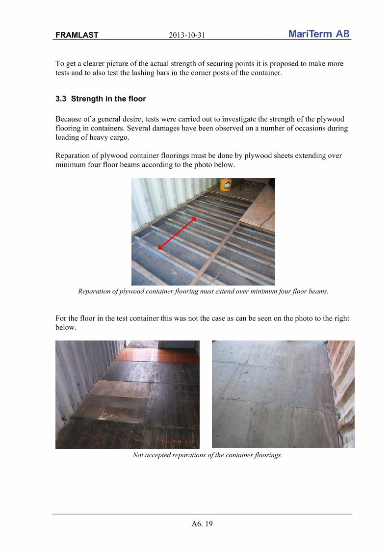
FRAMLAST 2013-10-31
A6. 19
To get a clearer picture of the actual strength of securing points it is proposed to make more tests and to also test the lashing bars in the corner posts of the container.
3.3 Strength in the floor
Because of a general desire, tests were carried out to investigate the strength of the plywood flooring in containers. Several damages have been observed on a number of occasions during loading of heavy cargo. Reparation of plywood container floorings must be done by plywood sheets extending over minimum four floor beams according to the photo below.
Reparation of plywood container flooring must extend over minimum four floor beams. For the floor in the test container this was not the case as can be seen on the photo to the right below.
Not accepted reparations of the container floorings.

FRAMLAST 2013-10-31
A6. 20
According to standard ISO 1496-5, the strength of container floors should be verified by maneuvering a fork lift with a minimum axle load of 2 x 2 730 kg = 5 460 kg. Each of the two wheels shall have a wheel print area of maximum 142 cm2. This generates a pressure in the print area of 19 kg/cm2. The testing procedure according to ISO 1496-5 is as follows: 6.8 Test No. 8 – Floor strength
6.8.1 General
This test shall be carried out to prove the ability of a container floor to withstand the concentrated dynamic loading during cargo operations involving trucks or similar devices.
For cargo securing devices installed at positions above the floor plane, the test force shall wherever possible be applied at 45° upwards and downwards from the horizontal plane. For devices installed at the roof plane (or other extreme heights) the test angle shall be 45° downwards.
The tensile force shall be continuously applied at the specified angle for 5 min.
6.8.2 Procedures
The test shall be performed using a test vehicle equipped with tyres, with an axle load of 5460 kg (i.e. 2730 kg on each of two wheels). It shall be so arranged that all points of contact between each wheel and a flat continuous surface lie within a rectangular envelope measuring 185 mm (in a direction parallel to the axle of the wheel) by 100 mm and that each wheel makes physical contact over an area within this envelope of not more than 142 cm2. The wheel width shall be nominally 180 mm and the wheel centres shall be nominally 760 mm. The test vehicle shall be maneuvered over the entire floor area of the container both longitudinally and transversally. The test shall be made with the container resting on four level supports under its four bottom corner fittings, with its base structure free to deflect.
6.8.3 On completion of the test, the container shall show neither permanent deformation nor abnormality which will render it unsuitable for use, and the dimensional requirements affecting handling, securing and interchange shall be satisfied.

FRAMLAST 2013-10-31
A6. 21
Two different types of forklifts were used; one electric and one diesel. The electric forklift, a CLARK CTM 16X, had the following dimensions:
- Forklift weight: 3540 kg - Front wheel diameter: 420 mm - Front wheel width: 140 mm
The electric forklift. The electric forklift was loaded with 1725 kg cargo to the total weight of 5265 kg and even if the cargo weight was increased with four men to get the entire cargo weight to rest on the front axle, the container flooring remained in complete condition.
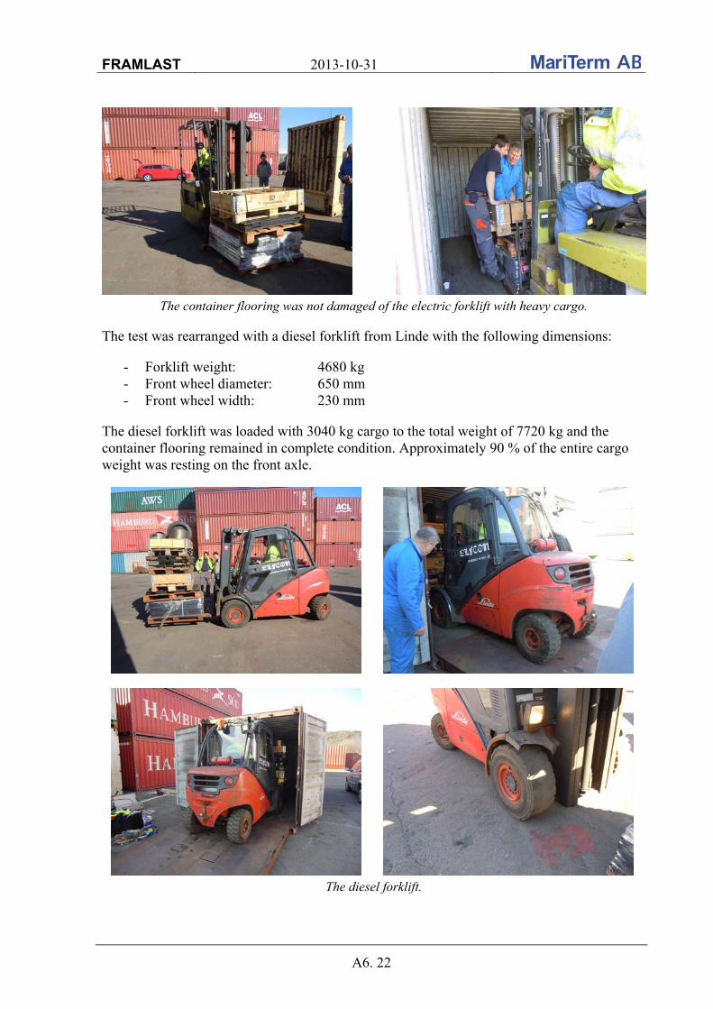
FRAMLAST 2013-10-31
A6. 22
The container flooring was not damaged of the electric forklift with heavy cargo. The test was rearranged with a diesel forklift from Linde with the following dimensions:
- Forklift weight: 4680 kg - Front wheel diameter: 650 mm - Front wheel width: 230 mm
The diesel forklift was loaded with 3040 kg cargo to the total weight of 7720 kg and the container flooring remained in complete condition. Approximately 90 % of the entire cargo weight was resting on the front axle.
The diesel forklift.

FRAMLAST 2013-10-31
A6. 23
4. SUMMERY AND CONCLUSIONS The result of the tests of the strength in the corrugation was: Strength of the corrugation Height from the floor / roof (mm) 0 600 1150 Strength in daN (≈ kg) 3400 917 750 This means that the strength by timber in the corrugations is limited to approximate 3.5 ton down at the floor and in the roof and to slightly less than one ton 600 mm up from the floor and down from the roof. In the middle of the container the timber in the corrugation is able to block 0.75 ton. It should be mentioned that the weight of the cargo to be blocked by the timber in corrugations is not equal to the weight of the cargo. The cargo weight to be blocked is adjusted taken into account the design accelerations and the friction between the cargo and the container floor, see the example below.
Example of blocking by timber The big bags in the photo above are blocked with shorings (100 × 100 mm) in the corrugation, approximately 600 mm up from the floor respectively 600 mm down from the roof. The coefficient of friction between the EU pallets and the plywood flooring is 0.5 and the friction between the pallets and the big bags is 0.4 (according to the Quick Lashing Guides included in IMO Model Course 3.18). The weight of the cargo that is blocked by the timber is calculated as:
)( vsh
b
aag
Fm
where Fb = blocking force according to the tests carried out in N ah = horizontal acceleration factor μs = static coefficient of friction av = vertical acceleration factor g = gravity acceleration in m/s2
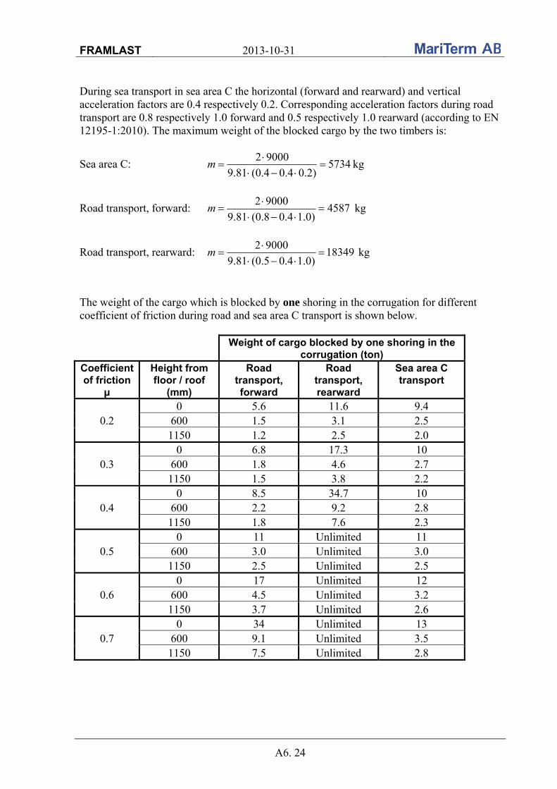
FRAMLAST 2013-10-31
A6. 24
During sea transport in sea area C the horizontal (forward and rearward) and vertical acceleration factors are 0.4 respectively 0.2. Corresponding acceleration factors during road transport are 0.8 respectively 1.0 forward and 0.5 respectively 1.0 rearward (according to EN 12195-1:2010). The maximum weight of the blocked cargo by the two timbers is:
Sea area C: 5734)2.04.04.0(81.9
90002
m kg
Road transport, forward: 4587)0.14.08.0(81.9
90002
m kg
Road transport, rearward: 18349)0.14.05.0(81.9
90002
m kg
The weight of the cargo which is blocked by one shoring in the corrugation for different coefficient of friction during road and sea area C transport is shown below.
Weight of cargo blocked by one shoring in the corrugation (ton)
Coefficient of friction
μ
Height from floor / roof
(mm)
Road transport, forward
Road transport, rearward
Sea area C transport
0.2 0 5.6 11.6 9.4
600 1.5 3.1 2.5 1150 1.2 2.5 2.0
0.3 0 6.8 17.3 10
600 1.8 4.6 2.7 1150 1.5 3.8 2.2
0.4 0 8.5 34.7 10
600 2.2 9.2 2.8 1150 1.8 7.6 2.3
0.5 0 11 Unlimited 11
600 3.0 Unlimited 3.0 1150 2.5 Unlimited 2.5
0.6 0 17 Unlimited 12
600 4.5 Unlimited 3.2 1150 3.7 Unlimited 2.6
0.7 0 34 Unlimited 13
600 9.1 Unlimited 3.5 1150 7.5 Unlimited 2.8
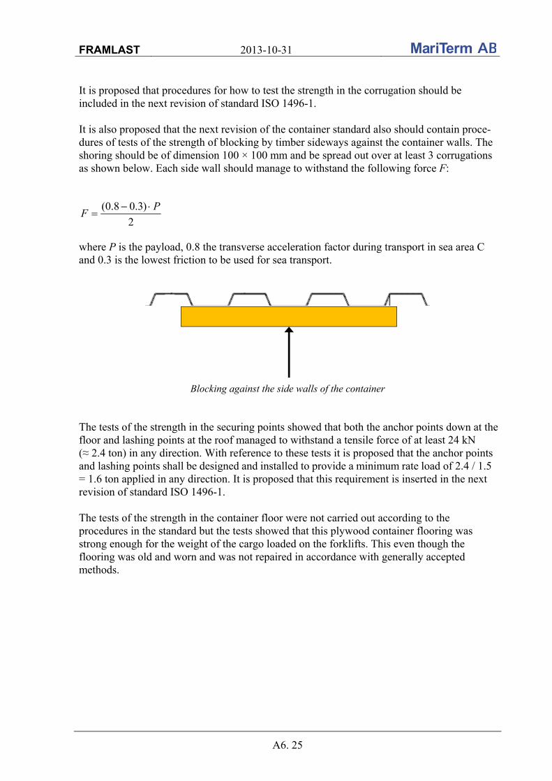
FRAMLAST 2013-10-31
A6. 25
It is proposed that procedures for how to test the strength in the corrugation should be included in the next revision of standard ISO 1496-1. It is also proposed that the next revision of the container standard also should contain proce-dures of tests of the strength of blocking by timber sideways against the container walls. The shoring should be of dimension 100 × 100 mm and be spread out over at least 3 corrugations as shown below. Each side wall should manage to withstand the following force F:
2
)3.08.0( PF
where P is the payload, 0.8 the transverse acceleration factor during transport in sea area C and 0.3 is the lowest friction to be used for sea transport.
Blocking against the side walls of the container The tests of the strength in the securing points showed that both the anchor points down at the floor and lashing points at the roof managed to withstand a tensile force of at least 24 kN (≈ 2.4 ton) in any direction. With reference to these tests it is proposed that the anchor points and lashing points shall be designed and installed to provide a minimum rate load of 2.4 / 1.5 = 1.6 ton applied in any direction. It is proposed that this requirement is inserted in the next revision of standard ISO 1496-1. The tests of the strength in the container floor were not carried out according to the procedures in the standard but the tests showed that this plywood container flooring was strong enough for the weight of the cargo loaded on the forklifts. This even though the flooring was old and worn and was not repaired in accordance with generally accepted methods.
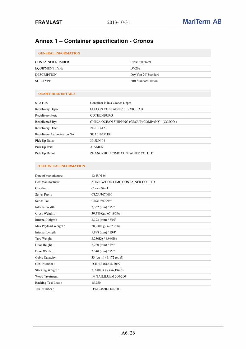
FRAMLAST 2013-10-31
A6. 26
Annex 1 – Container specification - Cronos
GENERAL INFORMATION
CONTAINER NUMBER CRXU3071691
EQUIPMENT TYPE DV20S
DESCRIPTION Dry Van 20' Standard
SUB-TYPE 20ft Standard 30 ton
ON/OFF HIRE DETAILS
STATUS Container is in a Cronos Depot
Redelivery Depot: ELFCON CONTAINER SERVICE AB
Redelivery Port: GOTHENBURG
Redelivered By: CHINA OCEAN SHIPPING (GROUP) COMPANY - (COSCO )
Redelivery Date: 21-FEB-12
Redelivery Authorization No: SCA01055218
Pick Up Date: 30-JUN-04
Pick Up Port: XIAMEN
Pick Up Depot: ZHANGZHOU CIMC CONTAINER CO. LTD
TECHINICAL INFORMATION
Date of manufacture: 12-JUN-04
Box Manufacturer ZHANGZHOU CIMC CONTAINER CO. LTD
Cladding: Corten Steel
Series From: CRXU3070000
Series To: CRXU3072996
Internal Width : 2,352 (mm) / 7'9"
Gross Weight : 30,480Kg / 67,196lbs
Internal Height : 2,393 (mm) / 7'10"
Max Payload Weight : 28,230Kg / 62,236lbs
Internal Length : 5,898 (mm) / 19'4"
Tare Weight : 2,250Kg / 4,960lbs
Door Height : 2,280 (mm) / 7'6"
Door Width : 2,340 (mm) / 7'8"
Cubic Capacity : 33 (cu m) / 1,172 (cu ft)
CSC Number : D-HH-3461/GL 7099
Stacking Weight : 216,000Kg / 476,194lbs
Wood Treatment : IM TAILILUEM 300/2004
Racking Test Load : 15,250
TIR Number : D/GL-4850-116/2003
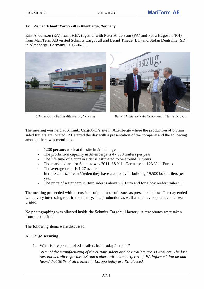
FRAMLAST 2013-10-31
A7. 1
A7. Visit at Schmitz Cargobull in Altenberge, Germany Erik Andersson (EA) from IKEA together with Peter Andersson (PA) and Petra Hugoson (PH) from MariTerm AB visited Schmitz Cargobull and Bernd Thiede (BT) and Stefan Deutschle (SD) in Altenberge, Germany, 2012-06-05.
Schmitz Cargobull in Altenberge, Germany Bernd Thiede, Erik Andersson and Peter Andersson The meeting was held at Schmitz Cargobull’s site in Altenberge where the production of curtain sided trailers are located. BT started the day with a presentation of the company and the following among others was mentioned:
- 1200 persons work at the site in Altenberge - The production capacity in Altenberge is 47,000 trailers per year - The life time of a curtain sider is estimated to be around 10 years - The market share for Schmitz was 2011: 38 % in Germany and 23 % in Europe - The average order is 1.27 trailers - In the Schmitz site in Vreden they have a capacity of building 19,500 box trailers per
year - The price of a standard curtain sider is about 25’ Euro and for a box reefer trailer 50’
The meeting proceeded with discussions of a number of issues as presented below. The day ended with a very interesting tour in the factory. The production as well as the development center was visited. No photographing was allowed inside the Schmitz Cargobull factory. A few photos were taken from the outside. The following items were discussed: A. Cargo securing
1. What is the portion of XL trailers built today? Trends?
99 % of the manufacturing of the curtain siders and box trailers are XL-trailers. The last percent is trailers for the UK and trailers with hamburger roof. EA informed that he had heard that 30 % of all trailers in Europe today are XL-classed.
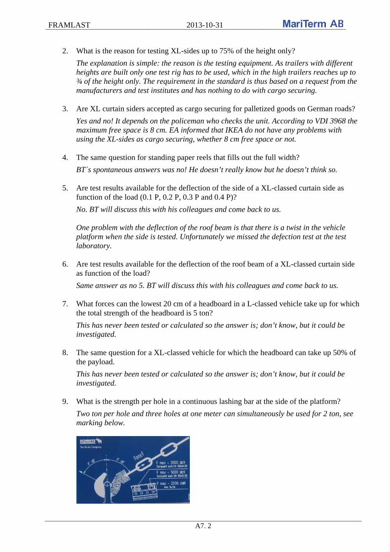
FRAMLAST 2013-10-31
A7. 2
2. What is the reason for testing XL-sides up to 75% of the height only?
The explanation is simple: the reason is the testing equipment. As trailers with different heights are built only one test rig has to be used, which in the high trailers reaches up to ¾ of the height only. The requirement in the standard is thus based on a request from the manufacturers and test institutes and has nothing to do with cargo securing.
3. Are XL curtain siders accepted as cargo securing for palletized goods on German roads?
Yes and no! It depends on the policeman who checks the unit. According to VDI 3968 the maximum free space is 8 cm. EA informed that IKEA do not have any problems with using the XL-sides as cargo securing, whether 8 cm free space or not.
4. The same question for standing paper reels that fills out the full width?
BT´s spontaneous answers was no! He doesn’t really know but he doesn’t think so.
5. Are test results available for the deflection of the side of a XL-classed curtain side as function of the load (0.1 P, 0.2 P, 0.3 P and 0.4 P)?
No. BT will discuss this with his colleagues and come back to us. One problem with the deflection of the roof beam is that there is a twist in the vehicle platform when the side is tested. Unfortunately we missed the defection test at the test laboratory.
6. Are test results available for the deflection of the roof beam of a XL-classed curtain side
as function of the load?
Same answer as no 5. BT will discuss this with his colleagues and come back to us.
7. What forces can the lowest 20 cm of a headboard in a L-classed vehicle take up for which the total strength of the headboard is 5 ton?
This has never been tested or calculated so the answer is; don’t know, but it could be investigated.
8. The same question for a XL-classed vehicle for which the headboard can take up 50% of the payload.
This has never been tested or calculated so the answer is; don’t know, but it could be investigated.
9. What is the strength per hole in a continuous lashing bar at the side of the platform?
Two ton per hole and three holes at one meter can simultaneously be used for 2 ton, see marking below.

FRAMLAST 2013-10-31
A7. 3
10. What shall the minimum distance be between the lashings if the force in each lashing is
two ton?
As answered above: three holes at one meter may be used. This may be three holes in a row. The continuous lashing bar is standard on new trailers.
11. Any improvements in design of lashing bars?
The answer was no. PA informed about problems with flat lashings in the continuous lashing bars. Schmitz often complement with ordinary lashing points that can be used for loop lashings where one hook has to lay flat on the floor.
12. What strength, number, position and configuration are normally used for stanchions?
Stanchions are not standard but can be ordered as special equipment. The stanchions are normally 2 m long with dimension 70×70×4 and each stanchion weighs 12 kg. Approximate 10 % of the orders of trailers are with stanchions and a typical order contains 16 stanchions and 8 x 3 stanchion holes. Each stanchion manages to withstand 400 kg on the top of the stanchion. During tests it is shown that the weak part is the hole in the floor and not the stanchion. It is also possible to order shorter stanchions with the dimension 80×80×4 for coils. These stanchions fit the 70×70 stanchion holes.
13. Are fixed lashings used in many trailers?
Schmitz approximately produces 200 – 250 trailers per year with fixed lashings, about 10%. Fixed lashings are often ordered in trailers for rent.
B. Expected future trailer designs in the coming 10 – 20 years
14. Trends regarding trailer length?
Trailers of length 13.6 m are built only. BT thinks that this length is here to stay. Trials are at present carried out in Germany with 14.9 m length that fits inside the total length requirement of 18.75 m total vehicle length for truck plus trailer. Schmitz is producing 50 or so swap bodies a year. The length of the swap bodies are mainly 7.4 m. BT doesn’t believe in any large future increase for swap bodies.
15. Trends regarding free height?
Of course the customers want as high trailers as possible. The inside standard height is 2.78 m at the rear and 2.68 m in front the end of the trailer, this with a coupling height of 1,150 mm. With coupling heights 1,050 and 950 mm the inner height of the trailers can be increased and almost 3 m can be reached. They are having problems in Germany with the maximum outside height of 4 m. If the trailer will pass through the Alps the height is limited to 3.8 m. Within the height requirement of 4 m, vehicles with an outside height of 4,040 mm can be built.
16. Trends regarding free width?
BT doesn’t believe in any change of the free width and it isn’t discussed. The outside width is 2.6 m for box reefer trailers and 2.55 for non-reefer vehicles, which gives a free inside width of 2.48 m.
FRAMLAST 2013-10-31
A7. 4
17. Expected future cargo volume?
No comments. The volume is given by 14 – 16 above.
18. Trends regarding tare weights and max payload?
Efforts to make a trailer lighter in weight are made every day. The weight of a MEGA trailer is just below 6 ton and of a standard trailer 6.6 ton. The X-light version weighs 5.4 ton and the lightest trailer produced in Altenberge was weighing 4.7 ton. The weight of the semi-trailer trucks is increasing and is today approximate 8 ton for a truck with single axle and 9 – 9.5 ton with a bogie. Thus, the lighter weight of the trailers is compensated by increased weight of the semi-trailer trucks. Within a 40 ton total vehicle weight, 40 – 8 – 6.6 = 25.4 ton payload can thus be obtained when using a single axle truck. Within a radius of 150 km from a rail terminal the total vehicle weight may be 44 ton and with a bogie truck the max payload can then be 44 – 9 – 6.6 = 28.4 ton. Box trailers have about the same weight as curtain siders, but reefer trailers have a weight of about 8 ton. 24 ton is an allowed bogie weight on a typical trailer triple bogie.
19. Trends regarding free side opening?
The maximum free side opening is about 13.1 m.
20. Trends regarding sliding roofs?
99 % of new trailers have sliding roof. The last percent is trailers for the UK and trailers with hamburger roof. BT said that it is standard with sliding roofs. Even if the roof never will be opened the customers want the trailers to be flexible. The roof is possible to open 13.6 – 2.3 = 11.3 m.
21. Trends regarding curtain contra box vehicle?
BT was not able to answer this question. After some discussions he estimated that approximately 95 % of the trailers in Germany are curtain siders. There are more box trailers in Scandinavia and in the US there are box trailers only. The box trailers are much more expensive than curtain siders.
22. Trends regarding side doors on box vehicles?
BT estimated orders of 100 – 150 box trailers per year with side doors mainly for the Scandinavian market.
23. Trends regarding piggy back outfitting?
More and more trailers with piggy back outfitting is ordered and today approximate 10 % of the produced trailers have this outfit. Such trailer costs EUR 2000 – 2500 more to produce and weighs 400 kg more than a standard trailer. The inside height of these trailers is 2.6 m only. Piggy back outfitting is normally ordered by major customers only.

FRAMLAST 2013-10-31
A7. 5
24. Trends regarding ferry outfitting according to ISO 9367?
Approximate 20 % of the total volume curtain siders produced at Schmitz is equipped with ferry outfitting, among others all orders from Scandinavia. The cost for this extra equipment is EUR 200.
25. Trends regarding weather protection especially for piggy back?
BT has heard of two cases where snow has come in through the roof during rail transport. This is not a problem. BT has never heard of moisture problems.
26. Trends regarding antitheft outfitting?
The insurance companies in France require that curtain siders are made with steel reinforcement not possible to cut up. The cost for this is EUR 450 extra. Approximate 20 % of the total volume of curtain siders has the antitheft outfitting.
Antitheft outfitting with steel reinforcement in the curtain in trailers for the French market
27. Trends regarding design according to EN 12640, EN 12642, ISO 9367?
No. All units produced at Schmitz Cargobull fulfill the standards EN 12640 and EN 12642 and 20 % the ISO 9367.
28. Trends regarding number of trailers, swap bodies (7.42 and 13.6 m) as well as pallet wide containers? Pro and cons for the different types.
No answer was given. Regarding swap bodies, see question 14 above. Schmitz made a prototype of a 45’ and pallet wide swap body two years ago but it was never put into production. BT believes in standard length and width in the future.
C. Concentrated loads
29. What are the requirements for load distribution in a typical trailer design?
It is allowed to stow two ton per meter. It is not permitted to overload the wheel axles and the king pin. BT will come back if he finds out any interesting for us regarding this question. There are no rules for maximum allowed deflection of a vehicle platform.
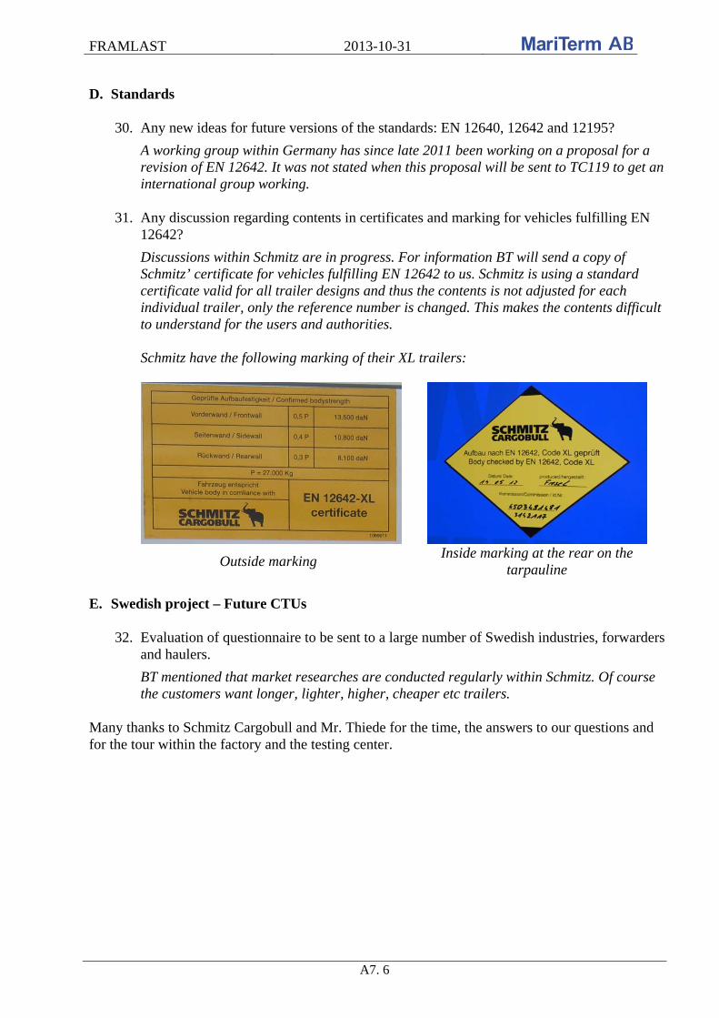
FRAMLAST 2013-10-31
A7. 6
D. Standards
30. Any new ideas for future versions of the standards: EN 12640, 12642 and 12195?
A working group within Germany has since late 2011 been working on a proposal for a revision of EN 12642. It was not stated when this proposal will be sent to TC119 to get an international group working.
31. Any discussion regarding contents in certificates and marking for vehicles fulfilling EN 12642?
Discussions within Schmitz are in progress. For information BT will send a copy of Schmitz’ certificate for vehicles fulfilling EN 12642 to us. Schmitz is using a standard certificate valid for all trailer designs and thus the contents is not adjusted for each individual trailer, only the reference number is changed. This makes the contents difficult to understand for the users and authorities. Schmitz have the following marking of their XL trailers:
Outside marking Inside marking at the rear on the
tarpauline E. Swedish project – Future CTUs
32. Evaluation of questionnaire to be sent to a large number of Swedish industries, forwarders
and haulers.
BT mentioned that market researches are conducted regularly within Schmitz. Of course the customers want longer, lighter, higher, cheaper etc trailers.
Many thanks to Schmitz Cargobull and Mr. Thiede for the time, the answers to our questions and for the tour within the factory and the testing center.

FRAMLAST 2013-10-31
A8. 1
A8. Visit from Krone A meeting was arranged at IKEAs office in Helsingborg 2012-06-20 with representatives from Krone; Jörg Sanders (JS), Frank Nordhoff (FN) and Johan Carlstedt (JC), the latter from Norfrig Sverige AB, the Krone Center in Sweden, and with Erik Andersson (EA) from IKEA and Peter Andersson (PA) and Petra Hugoson (PH) from MariTerm AB. The meeting started with a brief presentation of IKEA and MariTerm AB. The meeting was a bit stressful and no presentation of Krone was made. The production of trailers and the head office of Krone are located in Werlte, approximately 100 km west of Bremen, Germany. The average order is 1.8 trailers. The following items were discussed: A. Cargo securing
1. What is the portion of XL trailers built today? Trends?
Since almost 2 years 100 % of the manufacturing of curtain siders and box trailers are XL-trailers. The average lifetime of a trailer is 12 years. An estimation was made that the majority of all trailers is XL-trailers in 5 - 6 years.
2. What is the reason for testing XL-sides up to 75% of the height only?
It is an agreement between the manufacturers and test institutes to minimize the investment costs for equipment and handling. Note! Even if the sides are tested to 75 % of the height only, it is not prohibited to stow cargo above ¾ heights of the sides. It is allowed to use the entire sides of XL-trailers for cargo securing.
Equipment for testing XL-sides and headboards
3. Are XL curtain siders accepted as cargo securing for palletized goods on German roads?
Yes, if the total free space sideways do not exceed 8 cm and if the cargo units are rigid in form.
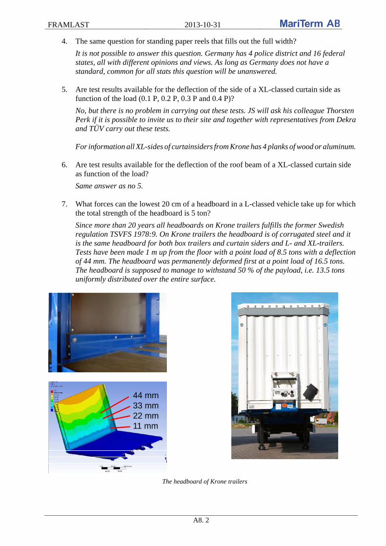
FRAMLAST 2013-10-31
A8. 2
4. The same question for standing paper reels that fills out the full width?
It is not possible to answer this question. Germany has 4 police district and 16 federal states, all with different opinions and views. As long as Germany does not have a standard, common for all stats this question will be unanswered.
5. Are test results available for the deflection of the side of a XL-classed curtain side as function of the load (0.1 P, 0.2 P, 0.3 P and 0.4 P)?
No, but there is no problem in carrying out these tests. JS will ask his colleague Thorsten Perk if it is possible to invite us to their site and together with representatives from Dekra and TÜV carry out these tests. For information all XL-sides of curtainsiders from Krone has 4 planks of wood or aluminum.
6. Are test results available for the deflection of the roof beam of a XL-classed curtain side
as function of the load?
Same answer as no 5.
7. What forces can the lowest 20 cm of a headboard in a L-classed vehicle take up for which the total strength of the headboard is 5 ton?
Since more than 20 years all headboards on Krone trailers fulfills the former Swedish regulation TSVFS 1978:9. On Krone trailers the headboard is of corrugated steel and it is the same headboard for both box trailers and curtain siders and L- and XL-trailers. Tests have been made 1 m up from the floor with a point load of 8.5 tons with a deflection of 44 mm. The headboard was permanently deformed first at a point load of 16.5 tons. The headboard is supposed to manage to withstand 50 % of the payload, i.e. 13.5 tons uniformly distributed over the entire surface.
44 mm33 mm22 mm11 mm
The headboard of Krone trailers

FRAMLAST 2013-10-31
A8. 3
8. The same question for a XL-classed vehicle for which the headboard can take up 50% of the payload.
See point 7.
9. What is the strength per hole in a continuous lashing bar at the side of the platform?
Two tons per hole and maximum 8 tons on one meter.
2 t / lashing point
max. 8 t / m
The lashing bar in Krone trailers Steel laths in Krone trailers
10. What shall the minimum distance be between the lashings if the force in each lashing is two ton?
As answered above: maximum 8 tons on one meter may be used.
11. Any improvements in design of lashing bars?
It is possible to order steel laths in Krone trailers (see photo above to the right). If two horizontal shoring beams are used in the two steel laths 30 % of the payload is blocked from moving rearwards which is equal to the test requirement of the rear wall according to EN 12642 (0.3 × P).
12. What strength, number, position and configuration are normally used for stanchions?
Stanchions (timber) are not standard but can be ordered as special equipment. The stanchions are normally 1950 mm long with dimension 80×80 and each stanchion weighs 8.5 kg. There is 10 positions for the stanchions in the side frame and in the center line; i.e. totally 30 positions for the stanchions.
10 pairs of post socketsin the side frame andalong centre line
Position of holes and strength of the stanchions (timber)
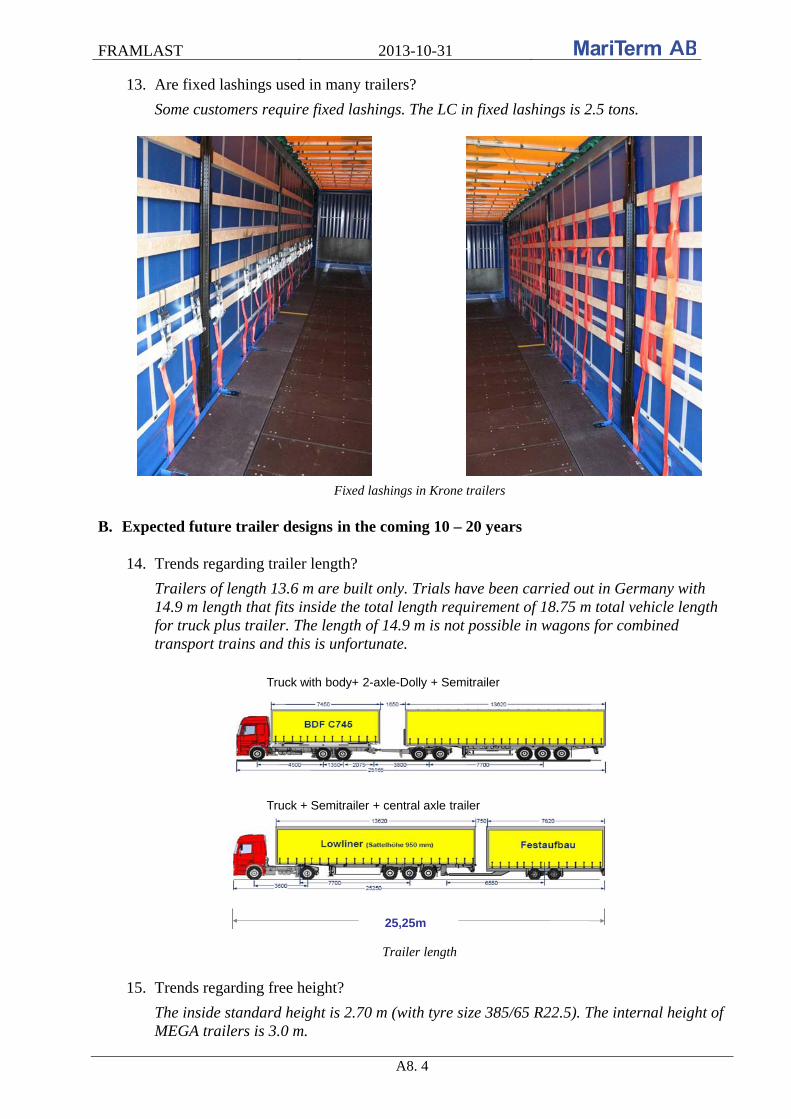
FRAMLAST 2013-10-31
A8. 4
13. Are fixed lashings used in many trailers?
Some customers require fixed lashings. The LC in fixed lashings is 2.5 tons.
Fixed lashings in Krone trailers B. Expected future trailer designs in the coming 10 – 20 years
14. Trends regarding trailer length?
Trailers of length 13.6 m are built only. Trials have been carried out in Germany with 14.9 m length that fits inside the total length requirement of 18.75 m total vehicle length for truck plus trailer. The length of 14.9 m is not possible in wagons for combined transport trains and this is unfortunate.
Truck + Semitrailer + central axle trailer
Truck with body+ 2-axle-Dolly + Semitrailer
25,25m
Trailer length 15. Trends regarding free height?
The inside standard height is 2.70 m (with tyre size 385/65 R22.5). The internal height of MEGA trailers is 3.0 m.
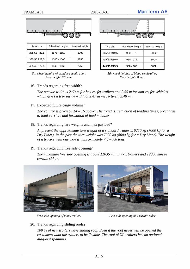
FRAMLAST 2013-10-31
A8. 5
Tyre size 5th wheel height Internal height
385/65 R22,5 1075 - 1150 2700
385/55 R22,5 1040 - 1060 2750
455/45 R22,5 1040 - 1060 2750
Tyre size 5th wheel height Internal height
385/55 R19,5 950 - 975 3000
435/50 R19,5 950 - 975 3000
445/45 R19,5 950 - 965 3000
5th wheel heights of standard semitrailer. Neck height 125 mm.
5th wheel heights of Mega semitrailer. Neck height 80 mm.
16. Trends regarding free width?
The outside width is 2.60 m for box reefer trailers and 2.55 m for non-reefer vehicles, which gives a free inside width of 2.47 m respectively 2.48 m.
17. Expected future cargo volume?
The volume is given by 14 – 16 above. The trend is: reduction of loading times, precharge to load carriers and formation of load modules.
18. Trends regarding tare weights and max payload?
At present the approximate tare weight of a standard trailer is 6250 kg (7000 kg for a Dry Liner). In the past the tare weight was 7000 kg (8000 kg for a Dry Liner). The weight of a tractor with one axle is approximately 7.6 – 7.8 tons.
19. Trends regarding free side opening?
The maximum free side opening is about 11835 mm in box trailers and 12000 mm in curtain siders.
Free side opening of a box trailer. Free side opening of a curtain sider.
20. Trends regarding sliding roofs?
100 % of new trailers have sliding roof. Even if the roof never will be opened the customers want the trailers to be flexible. The roof of XL-trailers has an optional diagonal spanning.
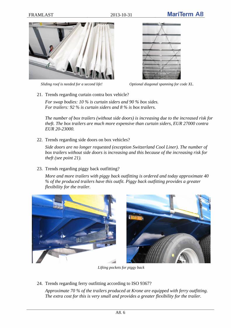
FRAMLAST 2013-10-31
A8. 6
Sliding roof is needed for a second life! Optional diagonal spanning for code XL.
21. Trends regarding curtain contra box vehicle?
For swap bodies: 10 % is curtain siders and 90 % box sides. For trailers: 92 % is curtain siders and 8 % is box trailers. The number of box trailers (without side doors) is increasing due to the increased risk for theft. The box trailers are much more expensive than curtain siders, EUR 27000 contra EUR 20-23000.
22. Trends regarding side doors on box vehicles?
Side doors are no longer requested (exception Switzerland Cool Liner). The number of box trailers without side doors is increasing and this because of the increasing risk for theft (see point 21).
23. Trends regarding piggy back outfitting?
More and more trailers with piggy back outfitting is ordered and today approximate 40 % of the produced trailers have this outfit. Piggy back outfitting provides a greater flexibility for the trailer.
Lifting pockets for piggy back
24. Trends regarding ferry outfitting according to ISO 9367?
Approximate 70 % of the trailers produced at Krone are equipped with ferry outfitting. The extra cost for this is very small and provides a greater flexibility for the trailer.
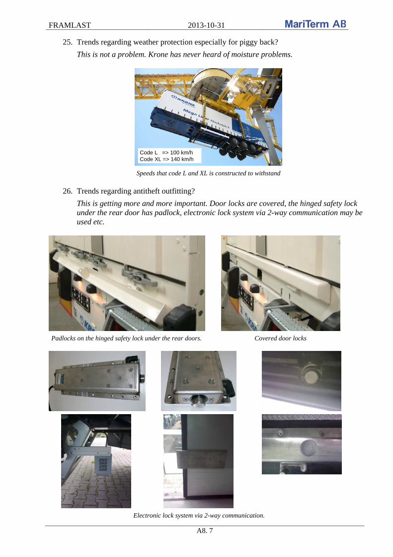
FRAMLAST 2013-10-31
A8. 7
25. Trends regarding weather protection especially for piggy back?
This is not a problem. Krone has never heard of moisture problems.
Code L => 100 km/hCode XL => 140 km/h
Speeds that code L and XL is constructed to withstand
26. Trends regarding antitheft outfitting?
This is getting more and more important. Door locks are covered, the hinged safety lock under the rear door has padlock, electronic lock system via 2-way communication may be used etc.
Padlocks on the hinged safety lock under the rear doors. Covered door locks
Electronic lock system via 2-way communication.

FRAMLAST 2013-10-31
A8. 8
27. Trends regarding design according to EN 12640, EN 12642, ISO 9367?
An answer may be given after a visit at Krone.
28. Trends regarding number of trailers, swap bodies (7.42 and 13.6 m) as well as pallet wide containers? Pro and cons for the different types.
The number of trailers is greater than the number of containers. The proportion of 45 ft pallet wide containers is less than 1 %. More information may be available after a visit at Krone.
C. Standards
29. Any new ideas for future versions of the standards: EN 12640, 12642 and 12195?
Krone is part of a working group within Germany working on a proposal for a revision of EN 12642. More information may be available after a visit at Krone.
30. Any discussion regarding contents in certificates and marking for vehicles fulfilling EN 12642?
An answer may be given after a visit at Krone. Many thanks to Krone for the time and for the answers to our questions. After the notes Petra Hugoson MariTerm AB
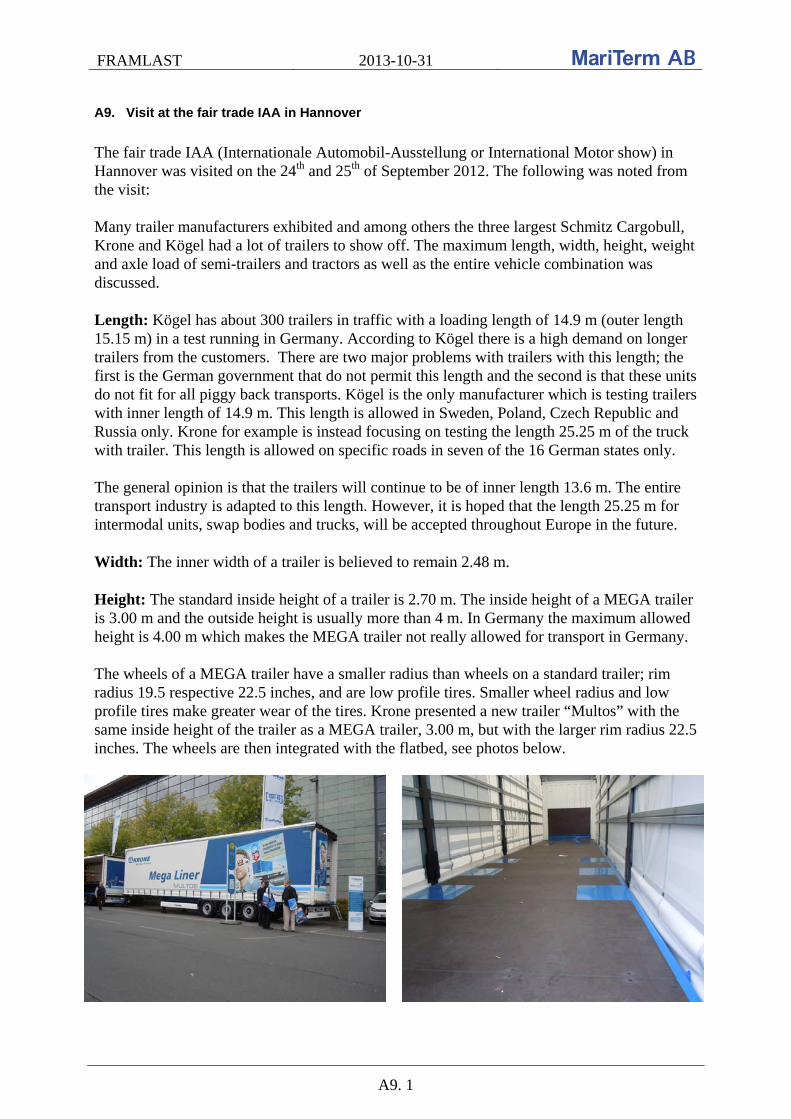
FRAMLAST 2013-10-31
A9. 1
A9. Visit at the fair trade IAA in Hannover
The fair trade IAA (Internationale Automobil-Ausstellung or International Motor show) in Hannover was visited on the 24th and 25th of September 2012. The following was noted from the visit: Many trailer manufacturers exhibited and among others the three largest Schmitz Cargobull, Krone and Kögel had a lot of trailers to show off. The maximum length, width, height, weight and axle load of semi-trailers and tractors as well as the entire vehicle combination was discussed. Length: Kögel has about 300 trailers in traffic with a loading length of 14.9 m (outer length 15.15 m) in a test running in Germany. According to Kögel there is a high demand on longer trailers from the customers. There are two major problems with trailers with this length; the first is the German government that do not permit this length and the second is that these units do not fit for all piggy back transports. Kögel is the only manufacturer which is testing trailers with inner length of 14.9 m. This length is allowed in Sweden, Poland, Czech Republic and Russia only. Krone for example is instead focusing on testing the length 25.25 m of the truck with trailer. This length is allowed on specific roads in seven of the 16 German states only. The general opinion is that the trailers will continue to be of inner length 13.6 m. The entire transport industry is adapted to this length. However, it is hoped that the length 25.25 m for intermodal units, swap bodies and trucks, will be accepted throughout Europe in the future. Width: The inner width of a trailer is believed to remain 2.48 m. Height: The standard inside height of a trailer is 2.70 m. The inside height of a MEGA trailer is 3.00 m and the outside height is usually more than 4 m. In Germany the maximum allowed height is 4.00 m which makes the MEGA trailer not really allowed for transport in Germany. The wheels of a MEGA trailer have a smaller radius than wheels on a standard trailer; rim radius 19.5 respective 22.5 inches, and are low profile tires. Smaller wheel radius and low profile tires make greater wear of the tires. Krone presented a new trailer “Multos” with the same inside height of the trailer as a MEGA trailer, 3.00 m, but with the larger rim radius 22.5 inches. The wheels are then integrated with the flatbed, see photos below.

FRAMLAST 2013-10-31
A9. 2
The general opinion is that the typical trailers will continue to have an inner height of 2.70 m. MEGA trailers will probably remain as an option only for customers and goods requiring higher heights. The king pin height varies between 880 mm and 1 200 mm. The king pin height for the MEGA liner Multos is 965 mm and the standard height is 1 050 mm, see figure below.
Weight: The maximum total weight of a vehicle in Germany is 40 tons. It will make little sense to permit 25.25 m vehicle combination in Germany as long as the total weight is limited to 40 tons. Axel load: The maximum gross vehicle weight (GVW) for a vehicle with two axles is 18 000 kg. The legal axle load on the front axle is 10 000 kg and on the rear axle 11 500 kg. Other notes:
Schmitz Cargobull introduced a new type of flatbed; anti slip coating with a dynamic
coefficient of friction of 0.6 against all materials, in dry as well as wet condition. The new coating can be ordered. A change of coating in an existing trailer costs approximately EUR 2000.
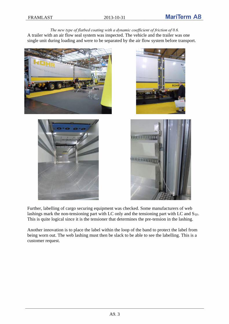
FRAMLAST 2013-10-31
A9. 3
The new type of flatbed coating with a dynamic coefficient of friction of 0.6. A trailer with an air flow seal system was inspected. The vehicle and the trailer was one single unit during loading and were to be separated by the air flow system before transport.
Further, labelling of cargo securing equipment was checked. Some manufacturers of web lashings mark the non-tensioning part with LC only and the tensioning part with LC and STF. This is quite logical since it is the tensioner that determines the pre-tension in the lashing. Another innovation is to place the label within the loop of the band to protect the label from being worn out. The web lashing must then be slack to be able to see the labelling. This is a customer request.
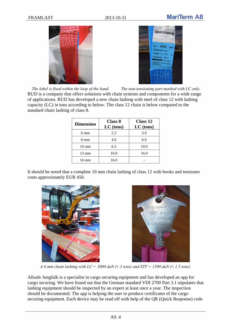
FRAMLAST 2013-10-31
A9. 4
The label is fixed within the loop of the band. The non-tensioning part marked with LC only. RUD is a company that offers solutions with chain systems and components for a wide range of applications. RUD has developed a new chain lashing with steel of class 12 with lashing capacity (LC) in tons according to below. The class 12 chain is below compared to the standard chain lashing of class 8.
Dimension Class 8
LC (tons) Class 12
LC (tons) 6 mm 2.2 3.0
8 mm 4.0 6.0
10 mm 6.3 10.0
13 mm 10.0 16.0
16 mm 16.0 -
It should be noted that a complete 10 mm chain lashing of class 12 with hooks and tensioner costs approximately EUR 450.
A 6 mm chain lashing with LC = 3000 daN (≈ 3 tons) and STF = 1500 daN (≈ 1.5 tons). Allsafe Jungfalk is a specialist in cargo securing equipment and has developed an app for cargo securing. We have found out that the German standard VDI 2700 Part 3.1 stipulates that lashing equipment should be inspected by an expert at least once a year. The inspection should be documented. The app is helping the user to produce certificates of the cargo securing equipment. Each device may be read off with help of the QR (Quick Response) code

FRAMLAST 2013-10-31
A9. 5
in marking of the device, see the photo to the right below. Further, the application is calculating the required number of top-over lashings to prevent cargo from sliding in forward, rearward and sideway directions.
Cargo securing app. The device may be read off with help of the QR code. One of the trailer manufacturers had a marking label showing that the strength of the side walls of their XL trailers is 0.5 g, see the photo to the left below. According to the standard EN 12642 XL the static test conditions for the strength of the side walls is 0.4 P. It was then found out that the strength of the vehicle body structure also can be demonstrated by driving tests. This has to be changed. The alternative test method with driving tests does not seem reasonable. Throughout the Framlast project it will be proposed that these tests are removed. Another trailer manufacturer showed a solution of too much free space sideways with laying aluminium laths, see the photo to the right below.
Incorrect marking of the strength sideways. Laying laths for blocking sideways. In one trailer we found the following cargo securing solution for efficient sideways securing. However, this solution did not convince us. The application of the web lashing was way too complicated.
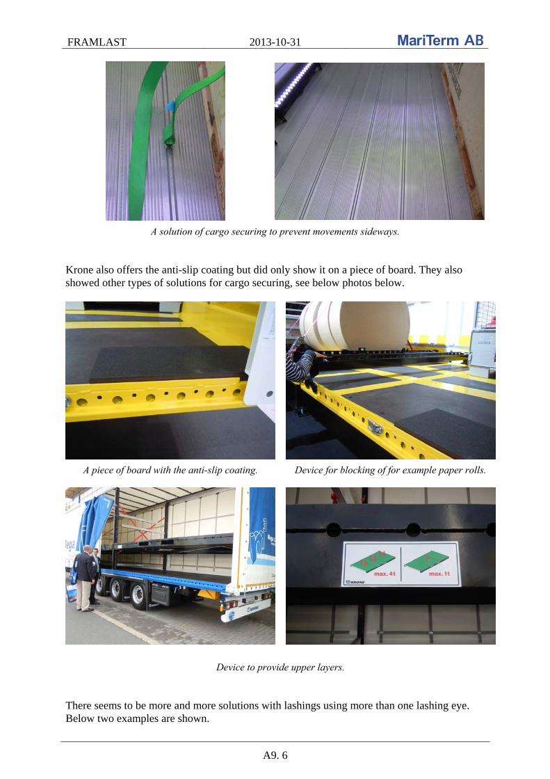
FRAMLAST 2013-10-31
A9. 6
A solution of cargo securing to prevent movements sideways. Krone also offers the anti-slip coating but did only show it on a piece of board. They also showed other types of solutions for cargo securing, see below photos below.
A piece of board with the anti-slip coating. Device for blocking of for example paper rolls.
Device to provide upper layers. There seems to be more and more solutions with lashings using more than one lashing eye. Below two examples are shown.
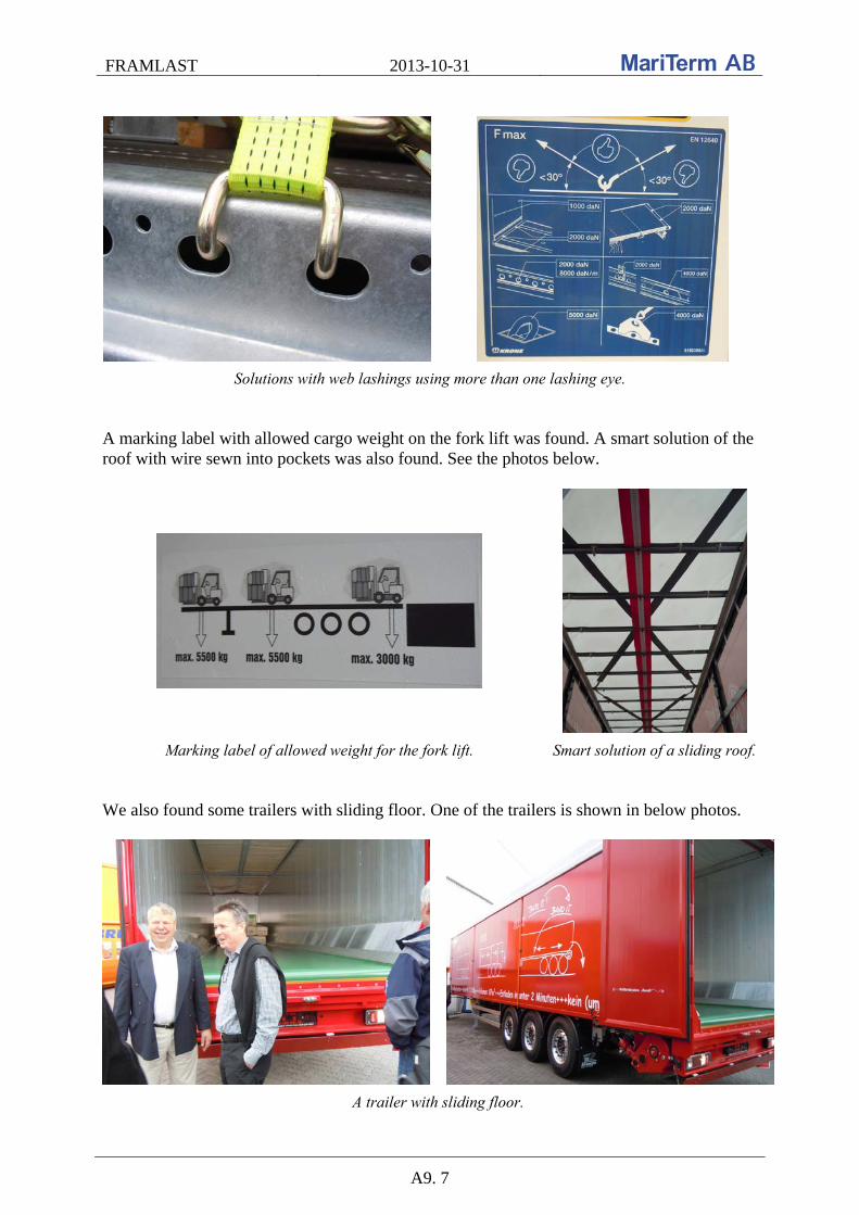
FRAMLAST 2013-10-31
A9. 7
Solutions with web lashings using more than one lashing eye. A marking label with allowed cargo weight on the fork lift was found. A smart solution of the roof with wire sewn into pockets was also found. See the photos below.
Marking label of allowed weight for the fork lift. Smart solution of a sliding roof. We also found some trailers with sliding floor. One of the trailers is shown in below photos.
A trailer with sliding floor.
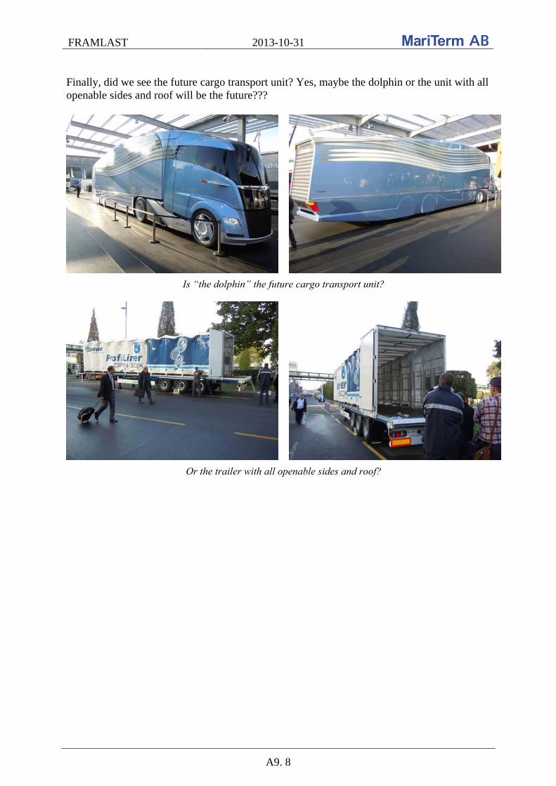
FRAMLAST 2013-10-31
A9. 8
Finally, did we see the future cargo transport unit? Yes, maybe the dolphin or the unit with all openable sides and roof will be the future???
Is “the dolphin” the future cargo transport unit?
Or the trailer with all openable sides and roof?

FRAMLAST 2013-10-31
A10. 1
A10. Visit at Ability Landin AB and telephone meeting with Transatlantic A meeting was arranged at Ability Landin AB’s office in Helsingborg 2013-01-11 with Tommy Landin (TL) from Ability Landin and Peter Andersson (PA) and Petra Hugoson (PH) from MariTerm AB. Stefan Lindgren (SL) from Transatlantic attended the meeting by telephone. Ability Landin is a consultancy within the transport and logistics sector. The company provides transportation solutions primarily between Sweden and the British Isles. Among others they offer container-based shipping line served by container ships in cooperation with Transatlantic. The discussions on the meeting were based on a comparison between the curtainside container (CUSI) and the 45’ pallet wide container (PWHC) with dimensions according to below: CUSI:
External: Internal:
Length: Width: Height: Length: Width: Height: Height, sideloading: Volume: Payload: Tare:
13 600 mm 2 500 mm 2 900 mm 13 450 mm 2 430/2 470 mm 2 580 mm 2 520 mm 85 m3
29 030 kg 4 970 kg
PWHC:
External: Internal: Door:
Length: Width: Height: Length: Width: Height: Volume: Width: Height: Payload: Tare:
13 715 mm 2 500 mm 2 896 mm 13 550 mm 2 430 mm 2 690 mm 89,1 m3
2 500 mm 2 580 mm 29 550 kg 4 450 kg
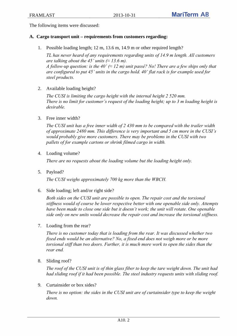
FRAMLAST 2013-10-31
A10. 2
The following items were discussed: A. Cargo transport unit – requirements from customers regarding:
1. Possible loading length; 12 m, 13.6 m, 14.9 m or other required length?
TL has never heard of any requirements regarding units of 14.9 m length. All customers are talking about the 45’ units (≈ 13.6 m). A follow-up question: is the 40’ (≈ 12 m) unit passé? No! There are a few ships only that are configured to put 45’ units in the cargo hold. 40’ flat rack is for example used for steel products.
2. Available loading height?
The CUSI is limiting the cargo height with the internal height 2 520 mm. There is no limit for customer’s request of the loading height; up to 3 m loading height is desirable.
3. Free inner width?
The CUSI unit has a free inner width of 2 430 mm to be compared with the trailer width of approximate 2480 mm. This difference is very important and 5 cm more in the CUSI’s would probably give more customers. There may be problems in the CUSI with two pallets of for example cartons or shrink filmed cargo in width.
4. Loading volume?
There are no requests about the loading volume but the loading height only.
5. Payload?
The CUSI weighs approximately 700 kg more than the WBCH. 6. Side loading; left and/or right side?
Both sides on the CUSI unit are possible to open. The repair cost and the torsional stiffness would of course be lower respective better with one openable side only. Attempts have been made to close one side but it doesn’t work; the unit will rotate. One openable side only on new units would decrease the repair cost and increase the torsional stiffness.
7. Loading from the rear?
There is no customer today that is loading from the rear. It was discussed whether two fixed ends would be an alternative? No, a fixed end does not weigh more or be more torsional stiff than two doors. Further, it is much more work to open the sides than the rear end.
8. Sliding roof?
The roof of the CUSI unit is of thin glass fiber to keep the tare weight down. The unit had had sliding roof if it had been possible. The steel industry requests units with sliding roof.
9. Curtainsider or box sides?
There is no option: the sides in the CUSI unit are of curtainsider type to keep the weight down.

FRAMLAST 2013-10-31
A10. 3
10. Adaption for combined transport by rail?
The relevant units in this flow are not transported by rail. The CUSI unit may be top lifted and are not equipped with pockets for grappler arms.
11. Stackability?
The loaded CUSI units may be stacked two high. This is not a problem on board.
12. Adaption for sea transport?
The customers do not care if the units are adapted for the sea transport or not. This is not their problem and they don’t want to pay extra for it.
13. External lashing points for sea transport according to ISO 9367?
The CUSI units are equipped with corner fittings for locking of units to the ship’s deck or to other units. No external lashing points are needed or available.
14. Pallet wide?
It is provided that the CUSI units are pallet wide. Otherwise it would not be useful.
15. TIR line?
There is no requirement on a TIR line. No valuable cargo is transported in the CUSI units under customs seal.
16. Marking according to EN 12642?
The sides in the CUSI unit are not used for cargo securing. The cargo inside the units is lashed. New units should be built with strong sides according to EN 12642 XL.
17. Handling possibilities; forks or top lifting?
The CUSI units are not stable enough to lift with a fork lift. The handling of the units is done by top lifting.
B. Cargo securing and cargo care – requirements from customers regarding:
18. Strength of side and end walls (EN 12642)?
The cargo is, as mentioned above, lashed within the CUSI unit. There are no requirements of strong sides or end walls from customers. The strength of the side and end walls of the unit today is 0.4 P respectively 0.3 P. In the PWHC unit the strength of the side and end walls is 0.6 P respectively 0.4 P.
19. Strength of lashing points (EN 12640)?
The CUSI is equipped with 13 fixed web lashings with lashing capacity (LC) 1600 daN (≈1600 kg) and pre-tension (STF) 320 daN (≈320 kg). Use of fixed lashing is not flexible and Transatlantic is not satisfied with these lashings. It is unknown if it is possible to fix lashings in the longitudinal beam. The customers require functional equipment only and do not specify number, strength or position of the lashings.
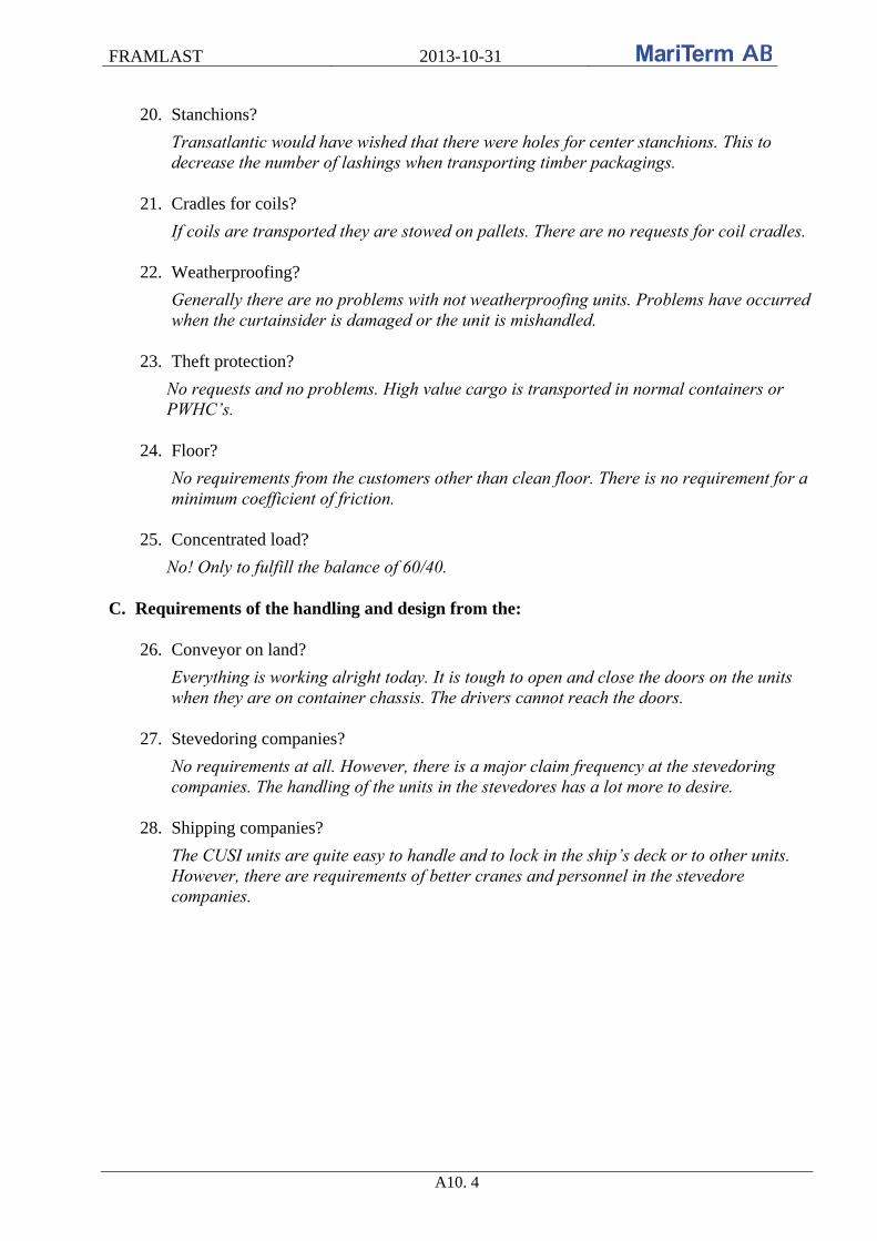
FRAMLAST 2013-10-31
A10. 4
20. Stanchions?
Transatlantic would have wished that there were holes for center stanchions. This to decrease the number of lashings when transporting timber packagings.
21. Cradles for coils?
If coils are transported they are stowed on pallets. There are no requests for coil cradles.
22. Weatherproofing?
Generally there are no problems with not weatherproofing units. Problems have occurred when the curtainsider is damaged or the unit is mishandled.
23. Theft protection?
No requests and no problems. High value cargo is transported in normal containers or PWHC’s.
24. Floor?
No requirements from the customers other than clean floor. There is no requirement for a minimum coefficient of friction.
25. Concentrated load?
No! Only to fulfill the balance of 60/40.
C. Requirements of the handling and design from the:
26. Conveyor on land?
Everything is working alright today. It is tough to open and close the doors on the units when they are on container chassis. The drivers cannot reach the doors.
27. Stevedoring companies?
No requirements at all. However, there is a major claim frequency at the stevedoring companies. The handling of the units in the stevedores has a lot more to desire.
28. Shipping companies?
The CUSI units are quite easy to handle and to lock in the ship’s deck or to other units. However, there are requirements of better cranes and personnel in the stevedore companies.

FRAMLAST 2013-10-31
A10. 5
Advantages with the CUSI unit:
The flexibility with loading also from the side The units are circulating in normal container traffic Stackable Increase the market for Transatlantic and their traffic to England
Disadvantages with the CUSI unit:
High repair cost due to damages to the sides during loading and unloading on board the ships
Poor torsional stiffness Lower loading height than for trailers and normal containers Less loading length than for trailers Less payload than for other units The loading width between the stanchions is limited to 2430 mm Difficulty of closing the unit Fixed web lashings
Many thanks to Tommy Landin and Stefan Lindgren for the time and for the answers to our questions. After the notes Petra Hugoson MariTerm AB

FRAMLAST 2013-10-31
A11. 1
A11. Visit at the fair trade Transport logistics in Munich The fair trade Transport & Logistics in Munich was visited on the 4th of June 2013. As before, it was found that this fair trade in Munich is much more focus on marketing people than on technologies, and to take advantage of the latest technological innovations primarily the fair trade in Hanover should be visited. However, there were some innovations that were presented and it was significantly more providers of cargo securing equipment than previously Munich fairs. The following was noted: Swap body with inside height 3 m DB Schenker and Krone presented a 45’ swap body with a loading volume of about 100 m2 and a free inside height of about 3 m within the total height 4 m, see details on the photos below.
Free inside height 2980 mm

FRAMLAST 2013-10-31
A11. 2
Required coupling height 830 mm
Outside height 4000 mm
Payload 24.5 ton and tare weight 6.5 ton
Automatic transmission system road - rail At the fair trade three independent systems for automatic transmission of cargo transport units between road and rail was presented according to below: Metrocargo Transmission system for combined cargo transport units; more information is found at www.metrocargoautomazioni.it.
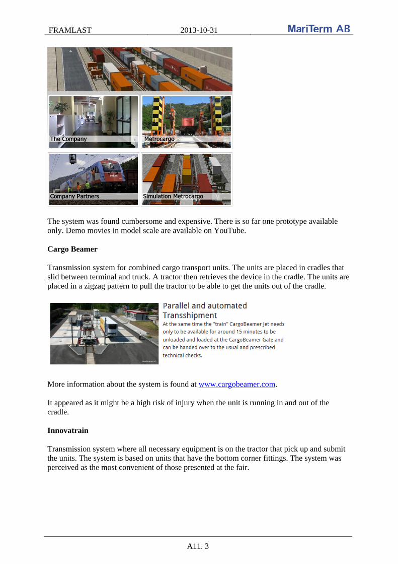
FRAMLAST 2013-10-31
A11. 3
The system was found cumbersome and expensive. There is so far one prototype available only. Demo movies in model scale are available on YouTube. Cargo Beamer Transmission system for combined cargo transport units. The units are placed in cradles that slid between terminal and truck. A tractor then retrieves the device in the cradle. The units are placed in a zigzag pattern to pull the tractor to be able to get the units out of the cradle.
More information about the system is found at www.cargobeamer.com. It appeared as it might be a high risk of injury when the unit is running in and out of the cradle. Innovatrain Transmission system where all necessary equipment is on the tractor that pick up and submit the units. The system is based on units that have the bottom corner fittings. The system was perceived as the most convenient of those presented at the fair.

FRAMLAST 2013-10-31
A11. 4
More information about the system is found at: http://www.innovatrain.ch ILU code Below example of new labeling according to the ILU code is shown:
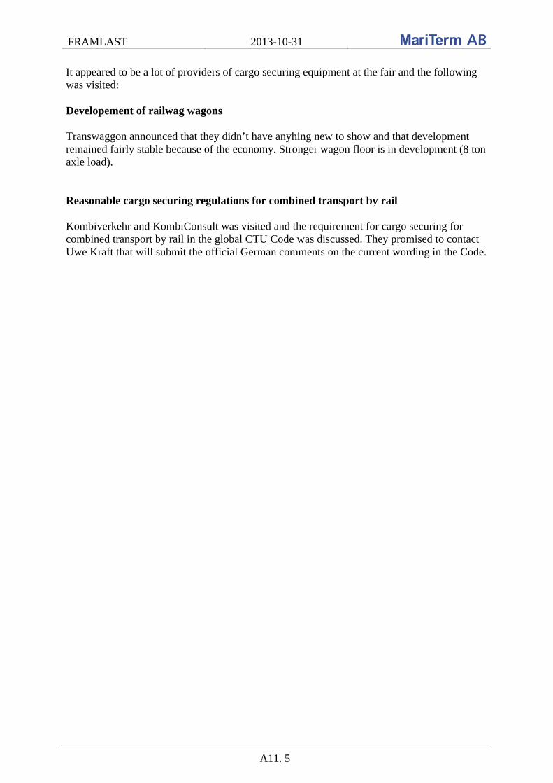
FRAMLAST 2013-10-31
A11. 5
It appeared to be a lot of providers of cargo securing equipment at the fair and the following was visited: Developement of railwag wagons Transwaggon announced that they didn’t have anyhing new to show and that development remained fairly stable because of the economy. Stronger wagon floor is in development (8 ton axle load). Reasonable cargo securing regulations for combined transport by rail Kombiverkehr and KombiConsult was visited and the requirement for cargo securing for combined transport by rail in the global CTU Code was discussed. They promised to contact Uwe Kraft that will submit the official German comments on the current wording in the Code.
![Intramural Research Report Final Final Version[2]](https://img.dokumen.tips/doc/110x75/577d1fe91a28ab4e1e91993e/intramural-research-report-final-final-version2.jpg)


![Biomimetics Report Final Version[1]](https://img.dokumen.tips/doc/110x75/5556b28dd8b42a9c798b546e/biomimetics-report-final-version1.jpg)