Embed Size (px)
Citation preview

Four-Wheel Drive Systems—Electronic Shift
Refer to Wiring Diagrams Section 308-07A, Four Wheel Drive Systems for schematic and connector information.
Principles of Operation
Transfer Case — Electronic Shift
The four-wheel drive electronic shift-on-the-fly feature electrically shifts the vehicle transfer case between 2WD, 4WD HIGH, and 4WD LOW. The system mode is selected by the operator through the mode select switch (MSS) on the instrument panel. The operator is informed which mode the system is in by two instrument cluster indicators: one for 4WD HIGH which appears as 4WD HIGH, and one for 4WD LOW, which appears as 4WD LOW. Shifts into 4WD HIGH can be made at any speed. When shifting into 4WD HIGH with the vehicle stationary, tooth blockage may occur preventing shift completion. When the vehicle is driven above 8 km/h (5 mph) the shift will complete. When shifting in or out of 4WD LOW, the four-wheel drive (4WD) control module requires that the vehicle speed be less than 5 km/h (3 mph), the brake pedal be applied, and the transmission be in NEUTRAL (automatic transmission) or the clutch pedal be depressed (manual transmission).
The transfer case shift motor is mounted externally on the transfer case. It drives a rotary cam which moves the mode fork and range fork within the transfer case between the 4WD HIGH, 4WD LOW, and 2WD range positions.
The four-wheel drive (4WD) control module controls the transfer case shift motor that shifts between 4WD HIGH, 4WD LOW, and 2WD modes.
The 4WD control module accomplishes shifts by interpreting inputs from the following:
� mode select switch (MSS)
� vehicle speed signal
� encoder plate position
� brake pedal switch
� digital transmission range (TR) sensor
� ignition switch
� transfer case shift motor
Based on these inputs, the 4WD control module controls the shifts into 2WD, 4WD HIGH or 4WD LOW with the following outputs:
� shift motor (clockwise)
� shift motor (counterclockwise)
Inspection and Verification — Electronic Shift
1. Visually inspect the following for obvious signs of mechanical and electrical damage.
Visual Inspection Chart
2. If the concern remains after the inspection, connect the diagnostic tool to the data link connector (DLC) located beneath the instrument panel and select the vehicle to be tested
from the diagnostic tool menu. If the diagnostic tool does not communicate with the vehicle:
SECTION 308-07A: Four-Wheel Drive Systems 2001 Ranger Workshop Manual
DIAGNOSIS AND TESTING Procedure revision date: 09/20/2002
Special Tool(s)
73III Automotive Meter 105-R0057 or equivalent
Worldwide Diagnostic System (WDS) 418-F224, New Generation STAR (NGS) Tester 418-F052, or equivalent diagnostic tool
Mechanical Electrical
� Axle shafts and universal joints � Driveshaft and universal joints � Fluid leaks � Matching tire size
� Battery junction box (BJB) fuse: � 1 (50A) � 3 (50A) � 13 (20A) � 30 (10A)
� Central junction box (CJB) fuse: � 28 (7.5A) (manual transmission) � 10 (7.5A) � 11 (7.5A) � 5 (15A)
� 4WD control module � Wiring harness � Mode select switch (MSS) � transfer case shift motor � Connector(s) � Circuitry
Page 1 of 232001 Ranger Workshop Manual
12/31/2009http://www.fordtechservice.dealerconnection.com/pubs/content/...

� check that the program card is correctly installed.
� check the connections to the vehicle.
� check the ignition switch position.
3. If the diagnostic tool still does not communicate with the vehicle, refer to the diagnostic tool manual.
4. Carry out the DATA LINK DIAGNOSTICS test. If the diagnostic tool responds with:
� CKT914, CKT915 or CKT70 = ALL ECUS NO RESP/NOT EQUIP, refer to Section 418-00.
� NO RESP/NOT EQUIP for 4WD control module, go to Pinpoint Test B.
� SYSTEM PASSED, retrieve and record the continuous diagnostic trouble codes (DTCs), erase the continuous DTCs and carry out the 4WD control module self-test.
5. If the DTCs retrieved are related to the concern, go to the 4WD Control Module Diagnostic Trouble Code (DTC) Index to continue diagnostics.
6. If no DTCs related to the concern are retrieved, carry out the Electronic Shift Function Test. Refer to Functional Test—Electronic Shift (Pinpoint Test A) in this section.
4WD Control Module Diagnostic Trouble Code (DTC) Index
Functional Test — Electronic Shift
PINPOINT TEST A: ELECTRONIC SHIFT FUNCTIONAL TEST
CAUTION: The function test must be carried out on a hard surface in a vacant area without traffic.
DTC Description Source Action
B1342 ECU is Defective 4WD control module
CLEAR the DTCs. REPEAT the 4WD control module self-test. If DTC B1342 is retrieved, INSTALL a new 4WD control module. REFER to Four-Wheel Drive (4WD) Control Module in this section. CLEAR the DTCs. REPEAT the self-test.
B1355 Ignition Run Circuit Failure 4WD control module
GO to Pinpoint Test C.
B1483 Brake Pedal Input Circuit Failure 4WD control module
GO to Pinpoint Test D.
B1485 Brake Pedal Input Battery Short 4WD control module
GO to Pinpoint Test D.
B1555 Ignition Run/Start Circuit Failure 4WD control module
GO to Pinpoint Test C.
C1728 Transfer Case Unable to Transition Between 2WD HIGH and 4WD HIGH
4WD control module
CARRY OUT the electronic shift function test. REFER to Function Test — Electronic Shift (Pinpoint Test A) in this section.
C1729 Transfer Case Unable to Transition Between 4WD HIGH and 4WD LOW
4WD control module
CARRY OUT the electronic shift function test. REFER to Function Test — Electronic Shift (Pinpoint Test A) in this section.
P0500 Vehicle Speed Sensor (VSS) Malfunction 4WD control module
GO to Pinpoint Test D.
P1812 Transmission 4WD Mode Select Circuit Failure
4WD control module
GO to Pinpoint Test C.
P1815 Transmission 4WD Mode Select Short Circuit to Ground
4WD control module
GO to Pinpoint Test C.
P1816 Transmission Neutral Safety Switch Circuit Failure
4WD control module
GO to Pinpoint Test D.
P1819 Transmission Neutral Safety Switch Short Circuit to Ground
4WD control module
GO to Pinpoint Test D.
P1849 Transmission Transfer Case Contact Plate A Short Circuit to Ground
4WD control module
GO to Pinpoint Test C.
P1853 Transmission Transfer Case Contact Plate B Short Circuit to Ground
4WD control module
GO to Pinpoint Test C.
P1857 Transmission Transfer Case Contact Plate C Short Circuit to Ground
4WD control module
GO to Pinpoint Test C.
P1861 Transmission Transfer Case Contact Plate D Short Circuit to Ground
4WD control module
GO to Pinpoint Test C.
P1867 Transmission Transfer Case Contact Plate General Circuit Failure
4WD control module
GO to Pinpoint Test C.
P1891 Transmission Transfer Case Contact Plate Ground Return Open Circuit
4WD control module
GO to Pinpoint Test C.
— For All Other DTCs 4WD control module
GO to Section 419-01
CONDITIONS DETAILS/RESULTS/ACTIONS
A1 CHECK INDICATOR PROVE-OUT
Start the vehicle while observing the four-wheel drive (4WD) indicators for prove-out.
Page 2 of 232001 Ranger Workshop Manual
12/31/2009http://www.fordtechservice.dealerconnection.com/pubs/content/...

� Did the indicators prove out?
Yes GO to A3.
No GO to A2.
A2 CHECK FOUR-WHEEL DRIVE (4WD) CONTROL MODULE COMMUNICATION
Diagnostic Tool
Retrieve 4WD control module self-test DTCs.
� Did the 4WD control module respond?
Yes REPAIR the instrument cluster as necessary. REFER to Section 413-01.
No GO to Pinpoint Test B.
A3 CHECK FOR TWO-WHEEL DRIVE (2WD) INDICATED
Start the vehicle and allow to idle.
Apply the brake pedal and hold.
Shift the transmission to NEUTRAL.
Turn the mode select switch (MSS) to 2WD while holding the shift conditions.
Observe the 4WD HIGH and 4WD LOW indicators.
� Are both indicators off?
Yes GO to A5.
No GO to A4.
A4 CHECK FOR THE PRESENCE OF FOUR-WHEEL DRIVE (4WD)
Shift the transmission to REVERSE and back the vehicle up 3.0 meters (10 feet) to relieve driveline windup.
Drive the vehicle forward for 3.0 meters (10 feet) and stop.
Press the brake pedal and hold.
Shift the transmission to NEUTRAL. Hold the shift conditions for 20 seconds.
Execute tight turns on a hard surface.
Check for the presence of driveline windup and tire scuff.
� Is driveline windup and tire scuff present?
Yes RETRIEVE 4WD control module self-test DTCs. If a self-test DTC related to the concern is retrieved, REFER to the 4WD Control Module Diagnostic Trouble Code (DTC) Index. If no DTC is retrieved, REFER to Section 308-07B and REPAIR the transfer case as necessary.
No If the 4WD HIGH indicator is ON, REFER to the symptom chart in Section 413-01to continue diagnosis. If the 4WD LOW indicator is ON, REFER to the symptom chart in Section 413-01 to continue diagnosis.
A5 VERIFY SHIFT TO 4WD HIGH
Turn the mode select switch (MSS) to 4X4 HIGH.
Listen for shift motor operation.
Wait for 20 seconds after MSS is turned to 4X4 HIGH. (The system will use up to five cycles of shift attempts trying to engage 4WD HIGH.)
� Is the 4WD HIGH indicator ON?
Yes GO to A7.
No GO to A6.
A6 ATTEMPT MECHANICAL ASSIST ENGAGEMENT
Drive the vehicle above 8 km/h (5 mph) for at least 20 seconds.
Stop the vehicle.
Observe the 4WD HIGH indicator.
� Is the 4WD HIGH indicator ON?
Page 3 of 232001 Ranger Workshop Manual
12/31/2009http://www.fordtechservice.dealerconnection.com/pubs/content/...

Yes GO to A7.
No RETRIEVE 4WD control module self-test DTCs. If a self-test DTC related to the concern is retrieved, REFER to the 4WD Control Module Diagnostic Trouble Code (DTC) Index. If no DTC related to the concern is retrieved, GO to Pinpoint Test C.
A7 CHECK FOR MECHANICAL ENGAGEMENT OF 4WD HIGH
Drive the vehicle for two minutes above 16 km/h (10 mph).
Execute tight turns on a hard surface.
Check for the presence of driveline windup and tire scuff.
� Is driveline windup and tire scuff present?
Yes GO to A8.
No 4WD HIGH did not mechanically engage. RETRIEVE 4WD control module self-test DTCs. If a self-test DTC related to the concern is retrieved, REFER to the 4WD Control Module Diagnostic Trouble Code (DTC) Index. If no DTC related to the concern is retrieved, GO to Pinpoint Test C.
A8 CHECK FOR CORRECT INDICATOR OPERATION ON 4WD LOW ENGAGEMENT
While driving the vehicle forward above 8 km/h (5 mph), turn the MSS to 4X4 LOW while observing the indicators for five seconds.
Turn the MSS to 4X4 HIGH.
Stop the vehicle and apply the parking brake.
Shift the transmission to PARK and release the brake pedal.
� Did the 4WD LOW indicator stay off?
Yes GO to A9.
No RETRIEVE 4WD control module self-test DTCs. If a self-test DTC related to the concern is retrieved, REFER to the 4WD Control Module Diagnostic Trouble Code (DTC) Index. If no DTC related to the concern is retrieved, GO to Pinpoint Test D.
A9 CHECK THE LOW RANGE INDICATOR ON IN ERROR
Turn the MSS to 4X4 LOW.
Apply and hold the brake pedal.
� Is the 4WD LOW indicator OFF?
Yes GO to A10.
No RETRIEVE 4WD control module self-test DTCs. If a self-test DTC related to the concern is retrieved, REFER to the 4WD Control Module Diagnostic Trouble Code (DTC) Index. If no DTC related to the concern is retrieved, GO to Pinpoint Test D.
A10 CHECK THE LOW RANGE INDICATOR FOR ON IN 4X4 LOW
Apply and hold the brake pedal.
Shift the transmission to NEUTRAL.
Listen for shift motor operation.
Hold the shift conditions for 20 seconds. (The system will use up to five cycles of shift attempts trying to engage 4X4 LOW.)
� Is the 4WD LOW indicator ON?
Yes GO to A12.
No GO to A11.
A11 ATTEMPT MECHANICAL ASSIST OF 4WD LOW ENGAGEMENT
CAUTION: Make sure there is a clear area behind the vehicle before backing up.
Shift the transmission to REVERSE and back the vehicle up 3.0 meters (10 feet) to relieve driveline windup and stop.
Drive the vehicle forward for 3.0 meters (10 feet) and stop.
Apply the brake pedal and hold.
Shift the transmission to NEUTRAL.
Observe the 4WD LOW indicator.
� Is the 4WD LOW indicator ON?
Yes GO to A12.
No RETRIEVE 4WD control module self-test DTCs. If a self-test DTC related to the concern is retrieved, REFER to the 4WD Control Module Diagnostic Trouble Code (DTC) Index. If no DTC related to the concern is retrieved, GO to Pinpoint Test D.
A12 CHECK FOR MECHANICAL ENGAGEMENT OF 4WD LOW
Page 4 of 232001 Ranger Workshop Manual
12/31/2009http://www.fordtechservice.dealerconnection.com/pubs/content/...

NOTE: Driveline windup and tire scuff is present in both 4WD HIGH and 4WD LOW. However, vehicle speed is severely limited in 4WD LOW.
Execute tight turns on a hard surface.
Check for the presence of driveline windup, tire scuff and reduced vehicle speed.
� Is driveline windup, tire scuff and reduced speed present?
Yes GO to A13.
No 4X4 LOW did not mechanically engage. RETRIEVE 4WD control module self-test DTCs. If a self-test DTC related to the concern is retrieved, REFER to the 4WD Control Module Diagnostic Trouble Code (DTC) Index. If no DTC related to the concern is retrieved, GO to Pinpoint Test D.
A13 CHECK FOR CORRECT INDICATOR OPERATION ON 4WD LOW DISENGAGEMENT
While driving the vehicle forward above 8 km/h (5 mph), turn the MSS to 4X4 HIGH while observing the indicators.
Turn the MSS to 4X4 LOW.
Stop the vehicle and apply the parking brake.
Shift the transmission to PARK and release the brake pedal.
� Is the 4WD LOW indicator ON?
Yes GO to A14.
No RETRIEVE 4WD control module self-test DTCs. If a self-test DTC related to the concern is retrieved, REFER to the 4WD Control Module Diagnostic Trouble Code (DTC) Index. If no DTC related to the concern is retrieved, GO to Pinpoint Test D.
A14 CHECK THE 4WD LOW INDICATOR
Turn the MSS to 4X4 HIGH.
Apply and hold the brake pedal.
� Is the 4WD LOW indicator ON?
Yes GO to A15.
No RETRIEVE 4WD control module self-test DTCs. If a self-test DTC related to the concern is retrieved, REFER to the 4WD Control Module Diagnostic Trouble Code (DTC) Index. If no DTC related to the concern is retrieved, GO to Pinpoint Test D.
A15 CHECK FOR 4WD LOW INDICATOR OFF IN 4WD HIGH
Press and hold the brake pedal.
Shift the transmission to NEUTRAL.
Listen for shift motor operation.
Hold the shift conditions for 20 seconds. (The system will use up to five cycles of shift attempts trying to engage 4WD HIGH.)
� Is the 4WD LOW indicator OFF?
Yes GO to A17.
No GO to A16.
A16 ATTEMPT MECHANICAL ASSIST OF 4WD LOW DISENGAGEMENT
Drive the vehicle forward above 8 km/h (5 mph) for at least five seconds.
Stop the vehicle.
Apply the brake pedal and hold.
Shift the transmission to NEUTRAL.
Observe the 4WD LOW indicator.
� Is the 4WD LOW indicator OFF?
Yes GO to A17.
No RETRIEVE 4WD control module self-test DTCs. If a self-test DTC related to the concern is retrieved, REFER to the 4WD Control Module Diagnostic Trouble Code (DTC) Index. If no DTC related to the concern is retrieved, GO to Pinpoint Test D.
A17 CHECK FOR MECHANICAL 4WD LOW DISENGAGEMENT AND 4WD HIGH ENGAGEMENT
Apply the brake.
CAUTION: Make sure there is a clear area behind the vehicle before backing up.
Shift the transmission to REVERSE and back the vehicle up 3.0 meters (10 feet) to relieve driveline windup.
Stop the vehicle.
Drive the vehicle forward and execute tight turns on a hard surface.
NOTE: Driveline windup and tire scuff is present in both 4WD HIGH and 4WD LOW. However, vehicle speed is severely limited in 4WD LOW.
Page 5 of 232001 Ranger Workshop Manual
12/31/2009http://www.fordtechservice.dealerconnection.com/pubs/content/...

Symptom Chart — Electronic Shift
Verify the presence of driveline windup and tire scuff. Also verify the increased vehicle speed from when 4WD LOW was engaged.
� Did 4WD HIGH engage and the vehicle speed increase?
Yes GO to A18.
No 4WD LOW is mechanically bound or locked. REPAIR the transfer case as necessary. REFER to Section 308-07B.
A18 CHECK THE 4WD HIGH TO 2WD SHIFT
Stop the vehicle.
Turn the MSS to 2WD and wait 20 seconds.
Listen for shift motor operation.
� Is the 4WD HIGH indicator OFF?
Yes GO to A20.
No GO to A19.
A19 ATTEMPT MECHANICAL ASSIST OF 4WD HIGH DISENGAGEMENT
Drive the vehicle forward above 8 km/h (5 mph) for at least 20 seconds.
Stop the vehicle.
Observe the 4WD HIGH indicator.
� Is the 4WD HIGH indicator OFF?
Yes GO to A20.
No RETRIEVE 4WD control module self-test DTCs. If a self-test DTC related to the concern is retrieved, REFER to the 4WD Control Module Diagnostic Trouble Code (DTC) Index. If no DTC related to the concern is retrieved, GO to Pinpoint Test C.
A20 VERIFY THE TRANSFER CASE MECHANICALLY DISENGAGED
Apply the parking brake.
Rotate the front driveshaft.
� Does the front driveshaft turn?
Yes The transfer case is operating correctly. INSTRUCT the customer on correct system operation.
No The transfer case did not disengage from 4WD HIGH. REPAIR the transfer case as necessary. REFER to Section 308-07B.
Symptom Chart
Condition Possible Sources Action
� No communication with the four-wheel drive (4WD) control module
� 4WD control module. � Central junction box (CJB). � CJB fuse:
� 35 (15A). � 10 (7.5A).
� Circuitry.
� GO to Pinpoint Test B.
� The vehicle does not shift between 2WD and 4WD modes correctly
� Battery junction box (BJB) fuse 13 (20A).
� Mode select switch (MSS). � Contact plate A, B, C, or D. � transfer case shift motor. � Circuitry. � 4WD control module. � Transfer case mechanism.
� GO to Pinpoint Test C.
� The vehicle does not shift between 4WD HIGH and 4WD LOW modes correctly
� BJB fuse 13 (20A). � Mode select switch (MSS). � Neutral safety switch. � Brake pedal position (BPP)
switch. � 4WD control module. � Transfer case. � Digital transmission range (TR)
sensor. � Circuitry.
� GO to Pinpoint Test D.
� The 4WD HIGH indicator is always on—4WD system operates correctly
� Circuitry. � Instrument cluster. � 4WD control module.
� REFER to the symptom chart in Section 413-01to continue diagnosis.
� The 4WD LOW indicator is always on � Powertrain control module (PCM).
� Circuitry. � Instrument cluster. � 4WD control module.
� REFER to the symptom chart in Section 413-01to continue diagnosis.
Page 6 of 232001 Ranger Workshop Manual
12/31/2009http://www.fordtechservice.dealerconnection.com/pubs/content/...

Pinpoint Tests — Electronic Shift
PINPOINT TEST B: NO COMMUNICATION WITH THE FOUR-WHEEL DRIVE (4WD) CONTROL MODULE
PINPOINT TEST C: THE VEHICLE DOES NOT SHIFT BETWEEN 2WD AND 4WD MODES CORRECTLY
CONDITIONS DETAILS/RESULTS/ACTIONS
B1 CHECK POWER TO 4WD CONTROL MODULE
4WD Control Module C281a
4WD Control Module C281b
Measure the voltage between 4WD control module C281a, pin 1, circuit 931 (OG) and ground; and between 4WD control module C281a, pin 2, circuit 704 (DG/LG) and ground.
� Are both voltage measurements greater than 10 volts?
Yes GO to B2.
No REPAIR the power supply as necessary. TEST the system for normal operation.
B2 CHECK 4WD CONTROL MODULE GROUND CIRCUIT
Measure the resistance between 4WD control module C281a pin 7, circuit 57 (BK), harness side and ground; and between 4WD control module C281b pin 2, circuit 570 (BK/WH), harness side and ground.
� Are both resistances less than 5 ohms?
Yes CARRY OUT the module self-test. If any DTCs are recorded, REFER to the 4WD Module Diagnostic Trouble Code (DTC) Index in this section. If the module still does not communicate witht the diagnostic tool, REFER to Section 418-00.
No REPAIR the circuit. TEST the system for normal operation.
CONDITIONS DETAILS/RESULTS/ACTIONS
C1 REVIEW THE DIAGNOSTIC TROUBLE CODES (DTCS)
Page 7 of 232001 Ranger Workshop Manual
12/31/2009http://www.fordtechservice.dealerconnection.com/pubs/content/...

Using the recorded results from the 4WD control module self-test:
� Are any DTCs retrieved?
Yes If DTC B1355 or DTC B1555is retrieved, GO to C15 . If DTC P1812 or DTC P1815 is retrieved, GO to C2 . If DTC P1849, DTC P1853, DTC P1857, DTC P1861, DTC P1867 or DTC P1891 is retrieved, GO to C9 .
No GO to C2.
C2 CHECK THE MODE SELECT SWITCH (MSS) — MONITOR THE 4WD CONTROL MODULE PID 4WD_SW
Monitor the 4WD control module PID 4WD_SW while cycling the MSS through 2WD, 4WD HIGH and 4WD LOW.
� Do the 4WD control module PID values agree with the MSS positions?
Yes GO to C4.
No GO to C3.
C3 CHECK THE MSS — ALL POSITIONS
MSS C284
Measure the resistance between MSS C284 pin 2, component side and pin 3, component side. Refer to the following chart:
MSS Position Resistance
2WD 3,705-4,095 Ohms
4WD HIGH 1,045-1,155 Ohms
4X4 LOW 342-378 Ohms
� Are the resistances within the specified values?
Yes GO to C4.
No INSTALL a new MSS. REFER to Mode Select Switch (MSS) in this section. CLEAR the DTCs. REPEAT the self-test.
C4 CHECK CIRCUIT 435 (YE/BK) FOR A SHORT TO VOLTAGE
4WD Control Module C281a
4WD Control Module C281b
Measure the voltage between 4WD control module C281b pin 1, circuit 435 (YE/BK), harness side and ground.
Page 8 of 232001 Ranger Workshop Manual
12/31/2009http://www.fordtechservice.dealerconnection.com/pubs/content/...

� Is any voltage present?
Yes REPAIR the circuit. CLEAR the DTCs. REPEAT the self-test.
No GO to C5.
C5 CHECK CIRCUIT 435 (YE/BK) FOR AN OPEN
Measure the resistance between MSS C284 pin 3, circuit 435 (YE/BK), harness side and 4WD control module C281b, pin 1, circuit 435 (YE/BK), harness side.
� Is the resistance less than 5 ohms?
Yes GO to C6.
No REPAIR the circuit. CLEAR the DTCs. REPEAT the self-test.
C6 CHECK CIRCUIT 465 (WH/LB) FOR A SHORT TO VOLTAGE
Measure the voltage between 4WD control module C281a pin 5, circuit 465 (WH/LB), harness side and ground.
� Is any voltage present?
Yes REPAIR the circuit. CLEAR the DTCs. REPEAT the self-test.
No GO to C7.
C7 CHECK CIRCUIT 465 (WH/LB) FOR A SHORT TO GROUND
Measure the resistance between 4WD control module C281a pin 5, circuit 465 (WH/LB), harness side and ground.
Page 9 of 232001 Ranger Workshop Manual
12/31/2009http://www.fordtechservice.dealerconnection.com/pubs/content/...

� Is the resistance greater than 10,000 ohms?
Yes GO to C8.
No REPAIR the circuit. CLEAR the DTCs. REPEAT the self-test.
C8 CHECK CIRCUIT 465 (WH/LB) FOR AN OPEN
Measure the resistance between MSS C284 pin 2, circuit 465 (WH/LB), harness side and 4WD control module C281a pin 5, circuit 465 (WH/LB), harness side.
� Is the resistance less than 5 ohms?
Yes GO to C9.
No REPAIR the circuit. CLEAR the DTCs. REPEAT the self-test.
C9 CHECK CIRCUIT 762 (YE/WH), CIRCUIT 763 (OG/WH), CIRCUIT 764 (BN/WH), CIRCUIT 770 (WH), AND CIRCUIT 771 (VT/YE) FOR A SHORT TO VOLTAGE
4WD Control Module C281a
4WD Control Module C281b
Measure the voltage between the following circuits at the 4WD control module connector pins and ground.
Circuit 4WD Control Module Connector and Pins
762 (YEWH) C281b pin 4
763 (OG/WH) C281b pin 13
764 (BN/WH) C281b pin 7
770 (WH) C281a pin 15
771 (VT/YE) C281a pin 11
� Is any voltage present?
Yes REPAIR the circuit(s) in question. CLEAR the DTCs. REPEAT the self-test.
No GO to C10.
C10 CHECK CIRCUIT 762 (YE/WH), CIRCUIT 763 (OG/WH), CIRCUIT 764 (BN/WH), CIRCUIT 770 (WH), AND CIRCUIT 771 (VT/YE) FOR A SHORT TO GROUND
Shift Motor Encoder C350
Measure the resistance between the following circuits at the 4WD control module connector pins and ground.
Circuit 4WD Control Module Connector and Pins
762 (YEWH) C281b pin 4
763 (OG/WH) C281b pin 13
764 (BN/WH) C281b pin 7
770 (WH) C281a pin 15
771 (VT/YE) C281a pin 11
Page 10 of 232001 Ranger Workshop Manual
12/31/2009http://www.fordtechservice.dealerconnection.com/pubs/content/...

� Are the resistances all over 10,000 ohms?
Yes GO to C11.
No REPAIR the circuit(s) in question. CLEAR the DTCs. REPEAT the self-test.
C11 CHECK CIRCUIT 762 (YE/WH) FOR OPEN
Measure the resistance between shift motor encoder C350 pin 6, circuit 762 (YE/WH), harness side and 4WD control module C281b pin 4, circuit 762 (YE/WH), harness side.
� Is the resistance less than 5 ohms?
Yes GO to C12.
No REPAIR the circuit. CLEAR the DTCs. REPEAT the self-test.
C12 CHECK CIRCUIT 763 (OG/WH), 764 (BN/WH), CIRCUIT 770 (WH), AND CIRCUIT 771 (VT/YE) FOR AN OPEN
Measure the resistance of the following circuits at the 4WD control module connector pins and shift motor encoder connector pins shown.
Circuit 4WD Control Module Connector and Pins Shift Motor Encoder Connector and Pins
763 (OG/WH) C281b pin 13 C350 pin 3
764 (BN/WH) C281b pin 7 C350 pin 2
770 (WH) C281a pin 15 C350 pin 1
771 (VT/YE) C281a pin 11 C350 pin 5
� Are all the resistances less than 5 ohms?
Yes GO to C13.
No REPAIR the circuit or circuit(s) in question. CLEAR the DTCs. REPEAT the self-test.
C13 CHECK CIRCUIT 777 (YE) AND CIRCUIT 778 (OG) FOR A SHORT TO VOLTAGE
Measure the voltage between 4WD control module C281a pin 17, circuit 777 (YE), harness side and ground; and between 4WD control module C281a pin 8, circuit 778 (OG), harness side and ground.
� Is any voltage present?
Yes REPAIR the circuit(s). CLEAR the DTCs. REPEAT the self-test.
No GO to C14.
C14 CHECK CIRCUIT 777 (YE) AND CIRCUIT 778 (OG) FOR AN OPEN
Page 11 of 232001 Ranger Workshop Manual
12/31/2009http://www.fordtechservice.dealerconnection.com/pubs/content/...
Shift Motor Encoder C350
Measure the resistance between 4WD control module C281a pin 17, circuit 777 (YE), harness side and shift motor encoder C350, pin 4, circuit 777 (YE), harness side; and measure the resistance between 4WD control module C281a pin 8, circuit 778 (OG), harness side and shift motor encoder C350 pin 7, circuit 778 (OG), harness side.
� Are the resistances less than 5 ohms?
Yes GO to C15.
No REPAIR the suspect circuit. CLEAR the DTCs. REPEAT the self-test.
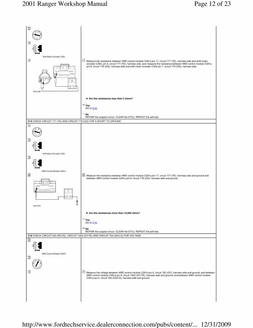
C15 CHECK CIRCUIT 777 (YE) AND CIRCUIT 778 (OG) FOR A SHORT TO GROUND
Shift Motor Encoder C350
4WD Control Module C281a
Measure the resistance between 4WD control module C281a pin 17, circuit 777 (YE), harness side and ground and between 4WD control module C281a pin 8, circuit 778 (OG), harness side and ground.
� Are the resistances more than 10,000 ohms?
Yes GO to C16.
No REPAIR the suspect circuit. CLEAR the DTCs. REPEAT the self-test.
C16 CHECK CIRCUIT 640 (RD/YE), CIRCUIT 1003 (GY/YE) AND CIRCUIT 704 (DG/LG) FOR VOLTAGE
4WD Control Module C281b
Measure the voltage between 4WD control module C281b pin 6, circuit 783 (GY), harness side and ground; and between 4WD control module C281a pin 9, circuit 1003 (GY/YE), harness side and ground; and between 4WD control module C281a pin 2, circuit 704 (DG/LG), harness side and ground.
Page 12 of 232001 Ranger Workshop Manual
12/31/2009http://www.fordtechservice.dealerconnection.com/pubs/content/...

� Are the voltages all over 10 volts?
Yes GO to C17.
No REPAIR the supply circuit. CLEAR the DTCs. REPEAT the self-test.
C17 CHECK CIRCUIT 931 (OG) FOR VOLTAGE
Measure the voltage between 4WD control module C281a pin 1, circuit 931 (OG), harness side and ground.
� Is the voltage between 9 and 16 volts?
Yes GO to C18.
No TEST the charging system. REFER to Section 414-00.
C18 CHECK FOR CORRECT 4WD CONTROL MODULE OPERATION
Disconnect all 4WD control module connectors (C281a, C281b) and the shift motor encoder connector (C350).
Check for:
� corrosion
� pushed-out pins
Connect all 4WD control module connectors and the shift motor encoder connector making sure they seat correctly.
Operate the system and verify the concern is still present.
� Is the concern still present?
Yes GO to C19.
No The system is operating correctly at this time. Concern may have been caused by a loose or corroded connector. CLEAR the DTCs. REPEAT the self-test.
C19 CHECK THE CONTACT PLATE ENCODER SWITCH
Monitor mode select switch (MSS) PIDs 2WD and 4WD HIGH.
Monitor contact plate PIDs PLATE_A, PLATE_B, PLATE_C and PLATE_D.
Cycle the MSS to 2WD and 4WD HIGH two times.
NOTE: Contact plate PIDs can only be read for approximately two seconds. To continue reading PIDs, cycle the MSS again.
Compare the contact plate PID values for each shift position selected by the MSS.
Plate PID MSS PID 2WD MSS PID 4HIGH
PLATE_A CLOSED OPEN
PLATE_B OPEN CLOSED
PLATE_C CLOSED CLOSED
PLATE_D CLOSED OPEN
� Do the contact plate PID values agree with the MSS switch PIDs?
Yes GO to C20.
Page 13 of 232001 Ranger Workshop Manual
12/31/2009http://www.fordtechservice.dealerconnection.com/pubs/content/...

PINPOINT TEST D: THE VEHICLE DOES NOT SHIFT BETWEEN 4WD HIGH AND 4WD LOW MODES CORRECTLY
No INSTALL a new transfer case shift motor. REFER to Transfer Case Shift Motor in this section. CLEAR the DTCs. REPEAT the self-test. If still inoperative, INSTALL a new 4WD control module. REFER to Four-Wheel Drive (4WD) Control Module in this section.
C20 CHECK THE TRANSFER CASE
Release the parking brake.
Using a wrench, manually shift the transfer case sector shaft to the full clockwise (2WD) direction while turning the rear driveshaft.
Engage the parking brake.
Rotate the front driveshaft.
� Does the front driveshaft turn?
Yes GO to C21.
No REPAIR the transfer case. REFER to Section 308-07B. TEST the system for normal operation.
C21 CHECK THE SECTOR SHAFT TURNING EFFORT
NOTE: The transfer case has three detented shift positions. The full clockwise position is 2WD, the next position is 4WD HIGH, and the full counterclockwise position is 4WD LOW. Normal operation should not take more than 45 Nm (33 lb-ft) to manually shift the transfer case.
Release the parking brake.
Using a torque wrench, manually shift the transfer case sector shaft in a counterclockwise direction to the 4WD HIGH detent position while rotating the rear driveshaft.
� Did the torque required to shift exceed 45 Nm (33 lb-ft)?
Yes REPAIR the transfer case as necessary. REFER to Section 308-07B. TEST the system for normal operation.
No GO to C22.
C22 CHECK THE TRANSFER CASE SHIFT TO 4WD HIGH AND 4WD LOW
Apply the parking brake.
Rotate the front driveshaft.
� Does the front driveshaft rotate?
Yes REPAIR the transfer case as necessary. REFER to Section 308-07B.
No INSTALL a new transfer case shift motor. REFER to Transfer Case Shift Motorin this section. CLEAR the DTCs. REPEAT the self-test. If still inoperative, INSTALL a new 4WD control module. REFER to Four-Wheel Drive (4WD) Control Module in this section.
CONDITIONS DETAILS/RESULTS/ACTIONS
D1 REVIEW THE FOUR-WHEEL DRIVE (4WD) CONTROL MODULE DIAGNOSTIC TROUBLE CODES (DTCs)
Using the recorded results from the 4WD control module self-test:
� Are any DTCs retrieved?
Yes If DTC P1816 is retrieved, GO to D3 . If DTC P1819 is retrieved, GO to D4 . If DTC B1483 or DTC B1485 is retrieved, GO to D8 . If DTC P0500 is retrieved, GO to D13 .
No GO to D2.
D2 VERIFY THE FUNCTION TEST HAS BEEN CARRIED OUT
Check the previous diagnostic procedure.
� Was the electronic shift function test carried out?
Yes GO to D3.
No
Page 14 of 232001 Ranger Workshop Manual
12/31/2009http://www.fordtechservice.dealerconnection.com/pubs/content/...

CARRY OUT the electronic shift function test. REFER to Functional Test — Electronic Shift (Pinpoint Test A) in this section.
D3 CHECK THE DIGITAL TRANSMISSION RANGE SENSOR PID NTRL_SW
Monitor 4WD control module PID NTRL_SW.
Place the gearshift lever in NEUTRAL.
Verify 4WD control module PID reads NTRL.
Shift the gear lever through all positions while monitoring 4WD control module PID NTRL_SW.
� Does the 4WD control module PID NTRL_SW read NTRL only for the neutral position?
Yes GO to D8.
No GO to D4.
D4 CHECK CIRCUIT 463 (RD/WH) FOR A SHORT TO GROUND
Place the gearshift lever in any position except neutral.
Measure the resistance between 4WD control module C281a pin 16, circuit 463 (RD/WH), harness side and ground.
� Is the resistance more than 10,000 ohms?
Yes GO to D5.
No REPAIR the circuit. SHIFT the gear lever between NEUTRAL and PARK twice. CLEAR the DTCs. REPEAT the self-test.
D5 CHECK CIRCUIT 463 (RD/WH) FOR A SHORT TO VOLTAGE
4WD Control Module C281a
Measure the voltage between 4WD control module C281a pin 16, circuit 463 (RD/WH), harness side and ground.
� Is any voltage present?
Yes GO to D7.
No GO to D6.
D6 CHECK TRANSMISSION RANGE (TR) SENSOR CIRCUIT 463 (RD/WH) FOR AN OPEN
Page 15 of 232001 Ranger Workshop Manual
12/31/2009http://www.fordtechservice.dealerconnection.com/pubs/content/...

TR Sensor C167
Measure the resistance between 4WD control module C281a pin 16, circuit 463 (RD/WH), harness side and TR sensor C167 pin 8, circuit 463 (RD/WH), harness side.
� Is the resistance less than 5 ohms?
Yes GO to D8.
No REPAIR the circuit. SHIFT the gear lever between NEUTRAL and PARK twice. CLEAR the DTCs. REPEAT the self-test.
D7 CHECK CIRCUIT 463 (RD/WH) FOR A SHORT TO VOLTAGE
Measure the voltage between 4WD control module C281a pin 16, circuit 463 (RD/WH), harness side and ground.
� Is there voltage present?
Yes REPAIR the circuit. SHIFT the gear lever between NEUTRAL and PARK twice. CLEAR the DTCs. REPEAT the self-test.
No INSTALL a new TR sensor. REFER to Section 307-01A or Section 307-01B. SHIFT the gear lever between NEUTRAL and PARK twice. CLEAR the DTCs. REPEAT the self-test.
D8 CHECK BRAKE PEDAL POSITION (BPP) SWITCH 4WD CONTROL MODULE PID
4WD Control Module C281a
4WD Control Module C281b
Apply the parking brake.
Press the brake pedal.
Monitor 4WD control module PID BOO.
� Does the PID value reflect the vehicle condition?
Yes GO to D13.
No GO to D9.
D9 CHECK CIRCUIT 810 (RD/LG) FOR A SHORT TO VOLTAGE
Page 16 of 232001 Ranger Workshop Manual
12/31/2009http://www.fordtechservice.dealerconnection.com/pubs/content/...

4WD Control Module C281a
Measure the voltage between 4WD control module C281a pin 12, circuit 810 (RD/LG), harness side and ground.
� Is there any voltage present?
Yes REPAIR the circuit. PRESS the brake pedal twice. CLEAR the DTCs. REPEAT the self-test.
No GO to D10.
D10 CHECK CIRCUIT 810 (RD/LG) FOR A SHORT TO GROUND
Measure the resistance between 4WD control module C281a pin 12, circuit 810 (RD/LG), harness side and ground.
� Is the resistance more than 10,000 ohms?
Yes GO to D11.
No REPAIR the circuit. PRESS the brake pedal twice. CLEAR the DTCs. REPEAT the self-test.
D11 CHECK CIRCUIT 810 (RD/LG) FOR VOLTAGE
Press and hold the brake pedal.
Measure the voltage between 4WD control module C281a pin 12, circuit 810 (RD/LG), harness side and ground.
� Is the voltage at least 10 volts?
Yes GO to D12.
No REPAIR the circuit. PRESS the brake pedal twice. CLEAR the DTCs. REPEAT the self-test.
D12 CHECK CIRCUIT 810 (RD/LG) FOR AN OPEN
Page 17 of 232001 Ranger Workshop Manual
12/31/2009http://www.fordtechservice.dealerconnection.com/pubs/content/...

BPP C278
Measure the resistance between 4WD control module C281a pin 12, circuit 810 (RD/LG), harness side and BPP switch C278 pin 2, circuit 810 (RD/LG), harness side.
� Is the resistance less than 5 ohms?
Yes GO to D13.
No REPAIR the circuit. PRESS the brake pedal twice. CLEAR the DTCs. REPEAT the self-test.
D13 CHECK THE SPEEDOMETER
4WD Control Module C281a
BPP C278
TR Sensor C167
Monitor the speedometer.
Monitor 4WD control module PID VSS2 while driving the vehicle 0 to 88.5 km/h (55 mph) at a steady rate.
� Does the 4WD control module PID VSS2 agree with the speedometer?
Yes GO to D15.
No GO to D14.
D14 CHECK POWERTRAIN CONTROL MODULE (PCM) CIRCUIT 679 (GY/BK) FOR AN OPEN
4WD Control Module C281b
PCM C175
Measure the resistance between 4WD control module 281b pin 12, circuit 679 (GY/BK), harness side and PCM C175, pin 68, circuit 679 (GY/BK), harness side.
Page 18 of 232001 Ranger Workshop Manual
12/31/2009http://www.fordtechservice.dealerconnection.com/pubs/content/...

� Is the resistance less than 5 ohms?
Yes GO to D15.
No REPAIR the circuit. DRIVE the vehicle to a speed of 40 mph (64 km/h). CLEAR the DTCs. REPEAT the self-test.
D15 CHECK THE MODE SELECT SWITCH (MSS) — MONITOR THE 4WD CONTROL MODULE PID 4WD_SW
4WD Control Module C281b
PCM C175
Monitor the 4WD control module PID 4WD_SW while cycling the MSS through 2WD, 4WD HIGH and 4WD LOW.
� Do the 4WD control module PID values agree with the MSS positions?
Yes GO to D17.
No GO to D16.
D16 CHECK THE MSS — ALL POSITIONS
MSS C284
Measure the resistance between MSS C284, pin 2, component side and pin 3, component side. Refer to the following chart:
MSS Position Resistance
2WD 3,705-4,095 Ohms
4WD HIGH 1,045-1,155 Ohms
4WD LOW 342-378 Ohms
� Are the resistances within the specified values?
Yes GO to D17.
No INSTALL a new MSS. REFER to Mode Select Switch (MSS) in this section. CLEAR the DTCs. REPEAT the self-test.
D17 CHECK FOR CORRECT 4WD CONTROL MODULE OPERATION
Disconnect all 4WD control module connectors (C281a, C281b) and the shift motor encoder connector (C350).
Page 19 of 232001 Ranger Workshop Manual
12/31/2009http://www.fordtechservice.dealerconnection.com/pubs/content/...

Check for:
� corrosion
� pushed-out pins
Connect all 4WD control module connectors and the shift motor encoder connector making sure they seat correctly.
Operate the system and verify the concern is still present.
� Is the concern still present?
Yes GO to D18.
No The system is operating correctly at this time. Concern may have been caused by a loose or corroded connector. CLEAR the DTCs. REPEAT the self-test.
D18 CHECK THE CONTACT PLATE ENCODER SWITCH
Monitor mode select switch (MSS) PIDs 2WD and 4WD LOW.
Monitor contact plate PIDs PLATE_A, PLATE_B, PLATE_C and PLATE_D.
NOTE: The contact plate PIDs can only be read for approximately two seconds. to continue reading, cycle the MSS again.
Cycle the MSS to 2WD and 4X4 LOW two times.
Compare the contact plate PID values for each shift position selected by the MSS.
Plate PID MSS PID 2WD MSS PID 4LOW
PLATE_A CLOSED OPEN
PLATE_B OPEN CLOSED
PLATE_C CLOSED OPEN
PLATE_D CLOSED CLOSED
� Do the contact plate PID values agree with the MSS PIDs?
Yes GO to D25.
No GO to D19.
D19 CHECK CIRCUIT 762 (YE/WH), CIRCUIT 763 (OG/WH), CIRCUIT 764 (BN/WH), CIRCUIT 770 (WH), AND CIRCUIT 771 (VT/YE) FOR A SHORT TO VOLTAGE
4WD Control Module C281a
4WD Control Module C281b
Measure the voltage between the following circuits at the 4WD control module connector pins and ground.
Circuit 4WD Control Module Connector and Pins
762 (YEWH) C281b pin 4
763 (OG/WH) C281b pin 13
764 (BN/WH) C281b pin 7
770 (WH) C281a pin 15
771 (VT/YE) C281a pin 11
� Is any voltage present?
Yes REPAIR the circuit(s) in question. CLEAR the DTCs. REPEAT the self-test.
No GO to D20.
D20 CHECK CIRCUIT 762 (YE/WH), CIRCUIT 763 (OG/WH), CIRCUIT 764 (BN/WH), CIRCUIT 770 (WH), AND CIRCUIT 771 (VT/YE) FOR A SHORT TO GROUND
Page 20 of 232001 Ranger Workshop Manual
12/31/2009http://www.fordtechservice.dealerconnection.com/pubs/content/...

Shift Motor Encoder C350
Measure the resistance between the following circuits at the 4WD control module connector pins and ground.
Circuit 4WD Control Module Connector and Pins
762 (YEWH) C281b pin 4
763 (OG/WH) C281b pin 13
764 (BN/WH) C281b pin 7
770 (WH) C281a pin 15
771 (VT/YE) C281a pin 11
� Are the resistances all over 10,000 ohms?
Yes GO to D21.
No REPAIR the circuit(s) in question. CLEAR the DTCs. REPEAT the self-test.
D21 CHECK CIRCUIT 762 (YE/WH) FOR AN OPEN
Measure the resistance between shift motor encoder C350 pin 6, circuit 762 (YE/WH), harness side and 4WD control module C281b pin 4, circuit 762 (YE/WH), harness side.
� Is the resistance less than 5 ohms?
Yes GO to D22.
No REPAIR the suspect circuit. CLEAR the DTCs. REPEAT the self-test.
D22 CHECK CIRCUIT 763 (OG/WH), 764 (BN/WH), CIRCUIT 770 (WH), AND CIRCUIT 771 (VT/YE) FOR AN OPEN
Measure the resistance of the following circuits at the 4WD control module connector pins and shift motor encoder connector pins shown.
Circuit 4WD Control Module Connector and Pins Shift Motor Encoder Connector and Pins
763 (OG/WH) C281b pin 13 C350 pin 3
764 (BN/WH) C281b pin 7 C350 pin 2
770 (WH) C281a pin 15 C350 pin 1
771 (VT/YE) C281a pin 11 C350 pin 5
� Are all the resistances less than 5 ohms?
Yes GO to D23.
No REPAIR the circuit or circuit(s) in question. CLEAR the DTCs. REPEAT the self-test.
D23 CHECK CIRCUIT 777 (YE) AND CIRCUIT 778 (OG) FOR A SHORT TO VOLTAGE
Page 21 of 232001 Ranger Workshop Manual
12/31/2009http://www.fordtechservice.dealerconnection.com/pubs/content/...

Measure the voltage between 4WD control module C281a pin 17, circuit 777 (YE), harness side and ground; and between 4WD control module C281a pin 8, circuit 778 (OG), harness side and ground.
� Is any voltage present?
Yes REPAIR the circuit(s). CLEAR the DTCs. REPEAT the self-test.
No GO to D24.
D24 CHECK CIRCUIT 777 (YE) AND CIRCUIT 778 (OG) FOR AN OPEN
Measure the resistance between 4WD control module C281a pin 17, circuit 777 (YE), harness side and shift motor encoder C350 pin 4, circuit 777 (YE), harness side; and between 4WD control module C281a pin 8, circuit 778 (OG), harness side and shift motor encoder C350 pin 7, circuit 778 (OG), harness side.
� Are the resistances less than 5 ohms?
Yes GO to D25.
No REPAIR the suspect circuit. CLEAR the DTCs. REPEAT the self-test.
D25 CHECK CIRCUIT 777 (YE) AND CIRCUIT 778 (OG) FOR A SHORT TO GROUND
Measure the resistance between 4WD control module C281a pin 17, circuit 777 (YE), harness side and ground and between 4WD control module C281a pin 8, circuit 778 (OG), harness side and ground.
� Are the resistances more than 10,000 ohms?
Yes GO to D26.
No REPAIR the suspect circuit. CLEAR the DTCs. REPEAT the self-test.
D26 CHECK THE TRANSFER CASE
Release the parking brake.
Using a wrench, manually shift the transfer case sector shaft to the full clockwise (2WD) direction while turning the rear driveshaft.
Engage the parking brake.
Rotate the front driveshaft.
� Does the front driveshaft turn?
Yes GO to D27.
No REPAIR the transfer case as necessary. REFER to Section 308-07B. TEST the system for normal operation.
D27 CHECK THE SECTOR SHAFT TURNING EFFORT
NOTE: The transfer case has three detented shift positions. The full clockwise position is 2WD, the next position is 4WD HIGH, and the full counterclockwise position is 4WD LOW. Normal operation should not take more than 45 Nm (33 lb-ft) to manually shift the transfer case.
Release the parking brake.
Page 22 of 232001 Ranger Workshop Manual
12/31/2009http://www.fordtechservice.dealerconnection.com/pubs/content/...

Using a torque wrench, manually shift the transfer case sector shaft in a counterclockwise direction to the 4WD HIGH detent position while rotating the rear driveshaft.
� Did the torque required to shift exceed 45 Nm (33 lb-ft)?
Yes REPAIR the transfer case as necessary. REFER to Section 308-07B. TEST the system for normal operation.
No GO to D28.
D28 CHECK THE TRANSFER CASE SHIFT TO 4WD HIGH AND 4WD LOW
Apply the parking brake.
Rotate the front driveshaft.
� Does the front driveshaft rotate?
Yes REPAIR the transfer case as necessary. REFER to Section 308-07B.
No INSTALL a new transfer case shift motor. REFER to Transfer Case Shift Motor in this section. CLEAR the DTCs. REPEAT the self-test. If still inoperative, INSTALL a new 4WD control module. REFER to Four-Wheel Drive (4WD) Control Module in this section. CLEAR the DTCs. REPEAT the self-test.
Page 23 of 232001 Ranger Workshop Manual
12/31/2009http://www.fordtechservice.dealerconnection.com/pubs/content/...