Embed Size (px)
Citation preview

FOUNDATION REPORTS For
EARTH RETAINING SYSTEMS (ERS)
June 2017
DIVISION OF ENGINEERING SERVICES GEOTECHNICAL SERVICES
Foundation Reports for Earth Retaining Systems June 2017
- i -
CONTENTS
1. INTRODUCTION .............................................................................................. 2 1.1 Intent of this Document ..................................................................................................... 2 1.2 Report Types...................................................................................................................... 2 1.3 Report Format .................................................................................................................... 3
2. STRUCTURE PRELIMINARY GEOTECHNICAL REPORT (SPGR) AND PRELIMARY FOUNDATION REPORT (PFR) ................................ 3
2.1 Scope of Work ................................................................................................................... 3 2.2 Project Description ............................................................................................................ 3 2.3 Exceptions ......................................................................................................................... 3 2.4 Field Investigation and Testing Program ........................................................................... 3 2.5 Laboratory Testing Program .............................................................................................. 3 2.6 Site Geology and Subsurface Conditions .......................................................................... 4 2.7 Scour Evaluation................................................................................................................ 4 2.8 Corrosion Evaluation ......................................................................................................... 4 2.9 Preliminary Site Seismicity and Analyses ......................................................................... 4 2.10 As-Built Data ..................................................................................................................... 5 2.11 Preliminary Recommendations.......................................................................................... 5 2.12 Additional Field Work and Laboratory Testing ................................................................ 5
3. FOUNDATION REPORT (FR) ........................................................................ 6 3.1 Scope of Work ................................................................................................................... 6 3.2 References ......................................................................................................................... 6 3.3 Project Description ............................................................................................................ 6 3.4 Exceptions ......................................................................................................................... 6 3.5 As-Built Data ..................................................................................................................... 6 3.6 Field Investigation and Testing Program ........................................................................... 6 3.7 Laboratory Testing Program .............................................................................................. 7 3.8 Site Geology and Subsurface Conditions .......................................................................... 7 3.9 Site Seismicity and Analyses ............................................................................................. 8 3.10 Scour Evaluation................................................................................................................ 8 3.11 Corrosion Evaluation ......................................................................................................... 9 3.12 Geotechnical Recommendations ....................................................................................... 9 3.13 Notes to Designer ............................................................................................................ 19 3.14 Construction Considerations............................................................................................ 19 3.15 Supplemental Project Information ................................................................................... 20 3.16 Appendices ...................................................................................................................... 21

Foundation Reports for Earth Retaining Systems June 2017
2
1. INTRODUCTION 1.1 Intent of this Document The intent of this document is to define the Department’s standard of practice for preparation of the Structures Preliminary Geotechnical Report (SPGR), the Preliminary Foundation Report (PFR), and the Foundation Report (FR) for earth retaining systems (ERS). Standardized and consistent report presentations for projects statewide benefit the Department’s staff, engineering consultants, bidders, and contractors. This document addresses report content only, it does not address investigative or design practice.
This document specifically pertains to all ERS whereby Structure Design prepares the PS&E, and is consistent with Bridge Memo to Designers 5-19, “Earth Retaining Systems Communication”. However, the GS practitioner is strongly encouraged to adapt and use these report preparation formats for standard plan ERS reports sent directly to the Districts.
1.2 Report Types 1.2.1 Structure Preliminary Geotechnical Report (SPGR) The SPGR is prepared during the early stages of a project to assist Structure Design in the preparation of an Advanced Planning Study (WBS 150.15.30 or 160.10.85). Often the number, location, and type of structures are not completely known and as a result the recommendations may be general. Typical fieldwork consists of a brief site visit only. The SPGR provides an overview of the existing conditions, site geology, seismicity, and, if possible, recommendations regarding suitable and unsuitable ERS types and foundation types. If appropriate, the SPGR should also discuss the anticipated field and laboratory work required to support the PFR and FR.
1.2.2 Preliminary Foundation Report (PFR) The PFR is prepared after completion of the SPGR and Advanced Planning Study, and prior to the ERS Type Selection (WBS 240.65). Generally more will be known about the number, location, and types of ERS, and the PFR is used to expand upon the information provided in the SPGR. The PFR will document existing conditions, provide preliminary recommendations, and identify the need for additional investigations and studies. Fieldwork will typically be minimal, but there may be projects where detailed field investigations are warranted.
1.2.3 Foundation Report (FR) The FR expands on data provided in the PFR, documents the results of site exploration, and provides final ERS design and construction recommendations (WBS 240.80). The FR becomes part of the contract documents via its inclusion in the Information Handout per Standard Specification Section 2-1.06B, “Supplemental Project Information”. As such, unlike the preliminary information presented in the SPGR and PFR, the information presented in the FR (and accompanying LOTB or borehole records) may be used as a basis to support or defend construction claims.
Foundation Reports for Earth Retaining Systems June 2017
3
1.3 Report Format Prepare a separate foundation report for each ERS. The intent of issuing one report per ERS is ease of interpretation by the structure designer, contractors and construction personnel, and more effective archiving.
The numbering convention is for the ease of use of this document. Section numbers should not be used in the reports because some sections may not be applicable. Section titles must be used.
The LOTB and As-Built LOTB sheets are not to be submitted as part of the FR. Microstation LOTB files and scanned copies of the As-Built LOTB sheets are sent by the Engineering Graphics Branch to the designer for inclusion within the Contract Plans.
Tables must be included within the body of the report and located as near as possible to the place where they are first referenced. Figures may be included in the attachments when necessary. It is preferable to place the Figures within the report body.
2. STRUCTURE PRELIMINARY GEOTECHNICAL REPORT (SPGR)
AND PRELIMARY FOUNDATION REPORT (PFR)
The following topics should be addressed in all Structure Preliminary Geotechnical Reports (SPGR) and Preliminary Foundation Reports (PFR). It is expected that as the foundation investigation process proceeds, the level of detail in the PFR will expand upon the content of the SPGR.
2.1 Scope of Work Summarize the scope and types of work performed to obtain the information supporting the preliminary recommendations.
2.2 Project Description Describe the project location, existing and/or proposed ERS and structures, and pertinent project information, such as the reason for constructing the ERS.
2.3 Exceptions Discuss all exceptions to Departmental policy relating to the SPGR or PFR. Approved “Request for Exception” forms must be included in the Appendix.
2.4 Field Investigation and Testing Program Provide an overview of the field investigations, if performed, to support the preliminary ERS recommendations.
2.5 Laboratory Testing Program Provide an overview of the laboratory-testing program, if performed, to support the preliminary ERS recommendations.
Foundation Reports for Earth Retaining Systems June 2017
4
2.6 Site Geology and Subsurface Conditions Provide a general description of the project site, geology, and known subsurface conditions including:
• Topography and geology • Types of soil and/or rock • Pertinent soil conditions or geologic hazards, such as
o Landslides or slope failures o Embankment failures o Collapsible foundation materials or conditions o Heave or expansive foundation materials
• Depth to rock • Groundwater elevation(s) and dates the measurements were made
2.7 Scour Evaluation Report the pertinent scour information, including the potential for scour and the predicted magnitude for scour.
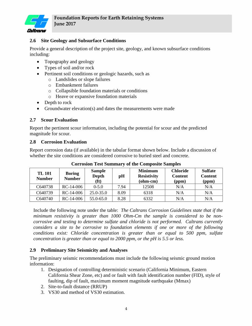
2.8 Corrosion Evaluation Report corrosion data (if available) in the tabular format shown below. Include a discussion of whether the site conditions are considered corrosive to buried steel and concrete.
Corrosion Test Summary of the Composite Samples
TL 101 Number
Boring Number
Sample Depth
(ft) pH
Minimum Resistivity (ohm-cm)
Chloride Content (ppm)
Sulfate Content (ppm)
C640738 RC-14-006 0-5.0 7.94 12508 N/A N/A C640739 RC-14-006 25.0-35.0 8.09 6318 N/A N/A C640740 RC-14-006 55.0-65.0 8.28 6332 N/A N/A
Include the following note under the table: The Caltrans Corrosion Guidelines state that if the minimum resistivity is greater than 1000 Ohm-Cm the sample is considered to be non-corrosive and testing to determine sulfate and chloride is not performed. Caltrans currently considers a site to be corrosive to foundation elements if one or more of the following conditions exist: Chloride concentration is greater than or equal to 500 ppm, sulfate concentration is greater than or equal to 2000 ppm, or the pH is 5.5 or less.
2.9 Preliminary Site Seismicity and Analyses The preliminary seismic recommendations must include the following seismic ground motion information:
1. Designation of controlling deterministic scenario (California Minimum, Eastern California Shear Zone, etc) and or fault with fault identification number (FID), style of faulting, dip of fault, maximum moment magnitude earthquake (Mmax)
2. Site-to-fault distance (RRUP) 3. VS30 and method of VS30 estimation.
Foundation Reports for Earth Retaining Systems June 2017
5
4. Peak ground acceleration (PGA) at the site. 5. If applicable, list all site factors used (e.g. near-fault factor, basin amplification factor,
etc). 6. If site is located within a deep sedimentary basin (as shown in the SDC, App. B), list
the depth to rock with a shear wave velocity of 1 km/sec (Z1.0) and 2.5 km/sec (Z2.5). 7. A statement of whether the Kh used in the standardized ERS designs is applicable to the
site. 8. If applicable, site-specific seismic recommendations using site response analysis and
design ground motion time-history, and 9. If necessary, recommendations for in-situ data acquisition and laboratory testing needed
for site-specific ground motion analysis, such as necessary depth of borings, gradation, shear wave velocities, strain dependent shear moduli and damping ratios.
Preliminary seismic recommendations must also address seismic hazards such as liquefaction potential, surface fault rupture potential, seismically induced settlement, tsunami and seismic slope instability, as applicable.
If other seismic recommendations are prepared and delivered under separate cover, (e.g., fault rupture reports) those reports should be referenced in this section.
2.10 As-Built Data Include discussion of relevant As-Built data, such as:
• As-Built LOTB • Existing ERS or other man-made features • As-Built geotechnical ultimate compressive, tensile, and lateral capacities of existing
foundations. • Construction records such as pile driving logs, pile load test reports, settlement
monitoring data, groundwater monitoring notes, etc.
2.11 Preliminary Recommendations Provide preliminary recommendations for the ERS. Recommendations must include the following:
• ERS types considered, and advantages and disadvantages of each • Recommended ERS and alternatives • ERS location (begin and end station, if available) and geometry (length, height) • Description of external loadings (surcharge, landslide, groundwater) • Description of site constraints (environmental, right-of-way, utilities, traffic,
construction, etc.) 2.12 Additional Field Work and Laboratory Testing Describe the anticipated scope and type of fieldwork and testing that may be required to complete the investigation and prepare the Foundation Report. Discuss the planned site investigation relating to potential need for entry permits, access road construction, lane closures etc. (see Geotechnical Investigations module).
Foundation Reports for Earth Retaining Systems June 2017
6
3. FOUNDATION REPORT (FR) The following topics, when applicable, must be addressed in the Foundation Report.
3.1 Scope of Work Summarize the scope and types of work performed to obtain the information supporting the foundation recommendations. Include a statement that the current report supersedes all previous reports (referenced by title and date). For example:
This Foundation Report supersedes the Preliminary Foundation Report for (Structure Name) dated (Date) and the Structure Preliminary Geotechnical Report for (Structure Name) dated (Date).
3.2 References Provide a list of the documents used to develop the recommendations presented in this report, such as fault rupture reports, and Type Selection and/or PDT meeting minutes.
3.3 Project Description Describe the project location, existing and/or proposed ERS, and pertinent project information, such as the reason for constructing the ERS and site constraints, including adjacent structures. The datum used to reference the elevations in the report should be included.
3.4 Exceptions Discuss all exceptions to Departmental policy and procedures relating to the investigation or design of the proposed ERS.
3.5 As-Built Data Include a discussion of relevant data for adjacent structures, such as:
• As-Built LOTB • Construction records such as pile driving logs, pile load test reports, settlement
monitoring data, groundwater monitoring notes, etc. • Existing adjacent ERS types and relevant design details • Performance of the noted structures
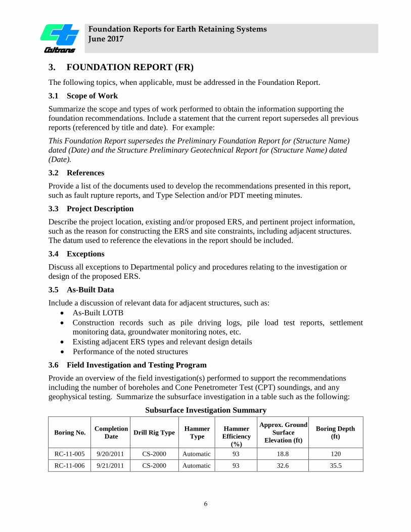
3.6 Field Investigation and Testing Program Provide an overview of the field investigation(s) performed to support the recommendations including the number of boreholes and Cone Penetrometer Test (CPT) soundings, and any geophysical testing. Summarize the subsurface investigation in a table such as the following:
Subsurface Investigation Summary
Boring No. Completion Date Drill Rig Type
Hammer
Type
Hammer Efficiency
(%)
Approx. Ground Surface
Elevation (ft)
Boring Depth (ft)
RC-11-005 9/20/2011 CS-2000 Automatic 93 18.8 120
RC-11-006 9/21/2011 CS-2000 Automatic 93 32.6 35.5

Foundation Reports for Earth Retaining Systems June 2017
7
3.7 Laboratory Testing Program Provide an overview of the laboratory-testing program, when performed, supporting the recommendations. A complete summary of results using the attached laboratory data summary table must be presented in the Appendix, along with all other test results.
3.8 Site Geology and Subsurface Conditions Describe the project site, topography, geology, and known subsurface conditions including:
• Types of soil/rock and their profile along the ERS layout line o Soil shear strength, apparent density, consistency, and compressibility o Rock unconfined compressive strength, hardness, degree of fracturing, and degree
of weathering. • Pertinent soil conditions or geologic hazards, such as
o Landslides or slope failures o Collapsible foundation materials or conditions o Heave or expansive foundation materials o Erosion or scour of existing slopes
• Depth to rock • Groundwater conditions determined by observations and/or analyses. Summarize
observed groundwater elevation(s) and observation dates in the tabular format shown below. Describe the methods and equipment used to measure the groundwater levels.
Groundwater Level Observations
Borehole ID Date0F
1
Ground Surface
Elevation (feet)
Depth to Groundwater
(feet)
Groundwater Elevation
(feet)
RC-11-005 11/10/2011
18.8 0.0 18.8
3/1/2012 0.3 18.5 12/11/2012 0.3 18.5
RC-11-008 11/10/2011
30.5 9.7 20.8
3/1/2012 11.5 19.0 12/11/2012 11.9 18.6
Present only factual information in this section, not how it relates to design and construction. Discussion of the site geology, geological features, and subsurface conditions as they relate to the ERS design and construction must be placed in the Foundation Recommendations and Construction Considerations sections respectively.
Foundation Reports for Earth Retaining Systems June 2017
8
3.9 Site Seismicity and Analyses The seismic recommendations must include the following seismic ground motion information:
1. Designation of controlling deterministic scenario (California Minimum, Eastern California Shear Zone, etc) and or fault with fault identification number (FID), style of faulting, dip of fault, maximum moment magnitude earthquake (Mmax)
2. Site-to-fault distance (RRUP) 3. VS30 and method of VS30 estimation. 4. Peak ground acceleration (PGA) at the site. 5. If applicable, list all site factors used (e.g. near-fault factor, basin amplification factor,
etc). 6. If site is located within a deep sedimentary basin (as shown in the SDC, App. B), list
the depth to rock with a shear wave velocity of 1 km/sec (Z1.0) and 2.5 km/sec (Z2.5). 7. Recommended horizontal acceleration (kh) and a statement of whether the Kh used in
the standardized ERS designs is applicable to the site. 8. If applicable, site-specific seismic recommendations using site response analysis and
design ground motion time-history, and 9. If necessary, recommendations for in-situ data acquisition and laboratory testing needed
for site-specific ground motion analysis, such as necessary depth of borings, gradation, shear wave velocities, strain dependent shear moduli and damping ratios.
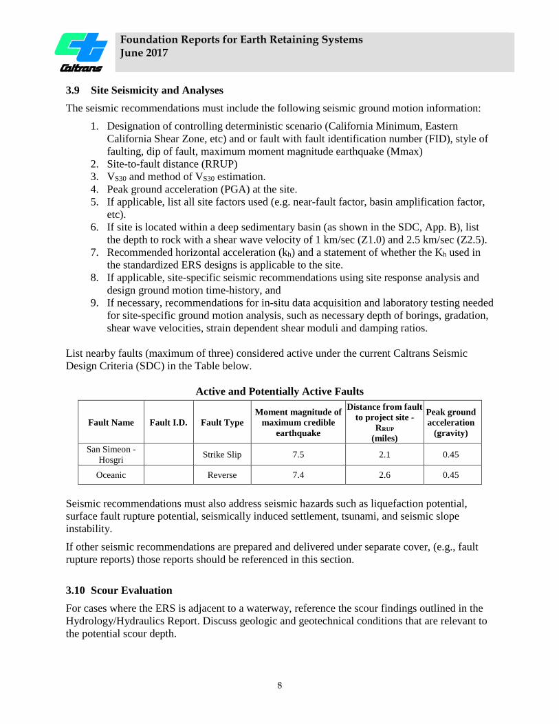
List nearby faults (maximum of three) considered active under the current Caltrans Seismic Design Criteria (SDC) in the Table below.
Active and Potentially Active Faults
Fault Name Fault I.D. Fault Type Moment magnitude of
maximum credible earthquake
Distance from fault to project site -
RRUP
(miles)
Peak ground acceleration
(gravity)
San Simeon - Hosgri
Strike Slip 7.5 2.1 0.45
Oceanic Reverse 7.4 2.6 0.45
Seismic recommendations must also address seismic hazards such as liquefaction potential, surface fault rupture potential, seismically induced settlement, tsunami, and seismic slope instability.
If other seismic recommendations are prepared and delivered under separate cover, (e.g., fault rupture reports) those reports should be referenced in this section.
3.10 Scour Evaluation For cases where the ERS is adjacent to a waterway, reference the scour findings outlined in the Hydrology/Hydraulics Report. Discuss geologic and geotechnical conditions that are relevant to the potential scour depth.

Foundation Reports for Earth Retaining Systems June 2017
9
3.11 Corrosion Evaluation Provide corrosion data for the site in the tabular format presented, and a discussion of the data. If corrosion testing was not completed during the foundation investigation, provide justification for the corrosion recommendations.
Corrosion Test Summary of the Composite Samples
TL 101 Number
Boring Number
Sample Depth (ft) pH
Minimum Resistivity (ohm-cm)
Chloride Content (ppm)
Sulfate Content (ppm)
C640738 RC-14-006 0-5.0 7.94 12508 N/A N/A C640739 RC-14-006 25.0-35.0 8.09 6318 N/A N/A C640740 RC-14-006 55.0-65.0 8.28 6332 N/A N/A
Include the following note under the table: “The Caltrans Corrosion Guidelines state that if the minimum resistivity is greater than 1000 Ohm-Cm the sample is considered to be non-corrosive and testing to determine sulfate and chloride is not performed. Caltrans currently considers a site to be corrosive to foundation elements if one or more of the following conditions exist: Chloride concentration is greater than or equal to 500 ppm, sulfate concentration is greater than or equal to 2000 ppm, or the pH is 5.5 or less”. 3.12 Geotechnical Recommendations Provide complete and concise recommendations by addressing the topics in the applicable portions of Section 3.12.1 and 3.12.2.
It is expected that the structure designer will analyze the following aspects of ERS design. Therefore, it is not necessary for the geoprofessional to address these topics in the Foundation Report:
1. Lateral sliding failure and deformation 2. Eccentricity evaluation 3. Internal structural stability
3.12.1 General Recommendations At the beginning of the recommendations section, discuss the following:
1. Description of the recommended ERS a. Location (begin and end station, length, and alignment) b. Design Height (maximum and minimum) c. Describe the representative cross sectional geometry and external loads.
Reference the plan sheets when possible. 2. Geotechnical design parameters
a. Soil and rock parameters used for geotechnical and structural analyses, presented in the table below. If applicable, provide parameters for short term and long term design.
b. Ground water conditions used for both short term and long term analyses, including results of seepage or flow analyses.
Foundation Reports for Earth Retaining Systems June 2017
10
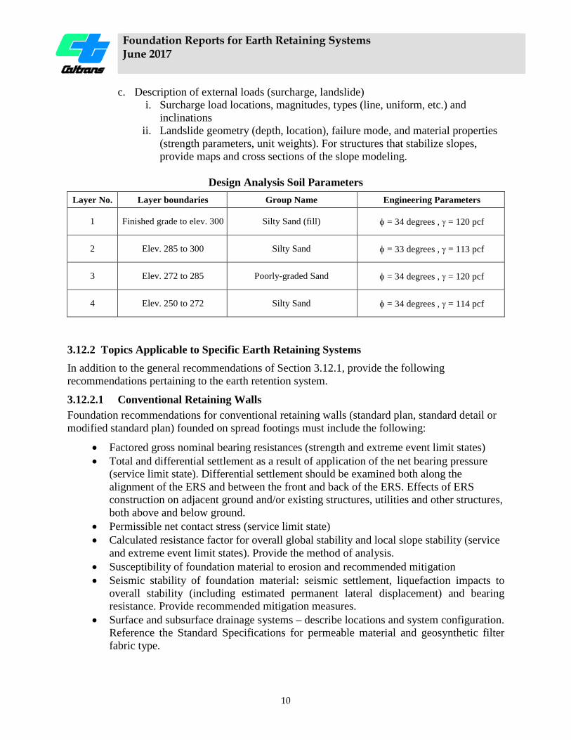
c. Description of external loads (surcharge, landslide) i. Surcharge load locations, magnitudes, types (line, uniform, etc.) and
inclinations ii. Landslide geometry (depth, location), failure mode, and material properties
(strength parameters, unit weights). For structures that stabilize slopes, provide maps and cross sections of the slope modeling.
Design Analysis Soil Parameters
Layer No. Layer boundaries Group Name Engineering Parameters
1 Finished grade to elev. 300 Silty Sand (fill) φ = 34 degrees , γ = 120 pcf
2 Elev. 285 to 300 Silty Sand φ = 33 degrees , γ = 113 pcf
3 Elev. 272 to 285 Poorly-graded Sand φ = 34 degrees , γ = 120 pcf
4 Elev. 250 to 272 Silty Sand φ = 34 degrees , γ = 114 pcf
3.12.2 Topics Applicable to Specific Earth Retaining Systems In addition to the general recommendations of Section 3.12.1, provide the following recommendations pertaining to the earth retention system.
3.12.2.1 Conventional Retaining Walls Foundation recommendations for conventional retaining walls (standard plan, standard detail or modified standard plan) founded on spread footings must include the following:
• Factored gross nominal bearing resistances (strength and extreme event limit states) • Total and differential settlement as a result of application of the net bearing pressure
(service limit state). Differential settlement should be examined both along the alignment of the ERS and between the front and back of the ERS. Effects of ERS construction on adjacent ground and/or existing structures, utilities and other structures, both above and below ground.
• Permissible net contact stress (service limit state) • Calculated resistance factor for overall global stability and local slope stability (service
and extreme event limit states). Provide the method of analysis. • Susceptibility of foundation material to erosion and recommended mitigation • Seismic stability of foundation material: seismic settlement, liquefaction impacts to
overall stability (including estimated permanent lateral displacement) and bearing resistance. Provide recommended mitigation measures.
• Surface and subsurface drainage systems – describe locations and system configuration. Reference the Standard Specifications for permeable material and geosynthetic filter fabric type.
Foundation Reports for Earth Retaining Systems June 2017
11
• Corrosiveness of foundation and retained soils and/or rock and water sources or drainage systems.
• Foundation improvements required to meet geotechnical design objectives, such as sub-excavation, foundation preloading and surcharge delay periods.
• Minimum unbonded ground anchor length for Type 7 walls that incorporate ground anchors.
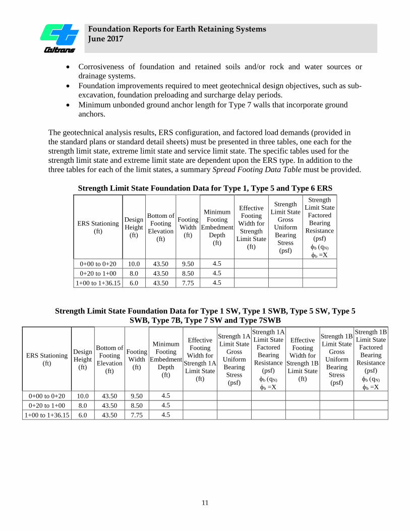
The geotechnical analysis results, ERS configuration, and factored load demands (provided in the standard plans or standard detail sheets) must be presented in three tables, one each for the strength limit state, extreme limit state and service limit state. The specific tables used for the strength limit state and extreme limit state are dependent upon the ERS type. In addition to the three tables for each of the limit states, a summary Spread Footing Data Table must be provided.
Strength Limit State Foundation Data for Type 1, Type 5 and Type 6 ERS
ERS Stationing (ft)
Design Height
(ft)
Bottom of Footing
Elevation (ft)
Footing Width
(ft)
Minimum Footing
Embedment Depth
(ft)
Effective Footing
Width for Strength
Limit State (ft)
Strength Limit State
Gross Uniform Bearing Stress (psf)
Strength Limit State Factored Bearing
Resistance (psf) φb (qN)
φb =X 0+00 to 0+20 10.0 43.50 9.50 4.5 0+20 to 1+00 8.0 43.50 8.50 4.5
1+00 to 1+36.15 6.0 43.50 7.75 4.5
Strength Limit State Foundation Data for Type 1 SW, Type 1 SWB, Type 5 SW, Type 5 SWB, Type 7B, Type 7 SW and Type 7SWB
ERS Stationing (ft)
Design Height
(ft)
Bottom of Footing
Elevation (ft)
Footing Width
(ft)
Minimum Footing
Embedment Depth
(ft)
Effective Footing
Width for Strength 1A Limit State
(ft)
Strength 1A Limit State
Gross Uniform Bearing Stress (psf)
Strength 1A Limit State Factored Bearing
Resistance (psf) φb (qN)
φb =X
Effective Footing
Width for Strength 1B Limit State
(ft)
Strength 1B Limit State
Gross Uniform Bearing Stress (psf)
Strength 1B Limit State Factored Bearing
Resistance (psf) φb (qN)
φb =X 0+00 to 0+20 10.0 43.50 9.50 4.5 0+20 to 1+00 8.0 43.50 8.50 4.5
1+00 to 1+36.15 6.0 43.50 7.75 4.5
Foundation Reports for Earth Retaining Systems June 2017
12
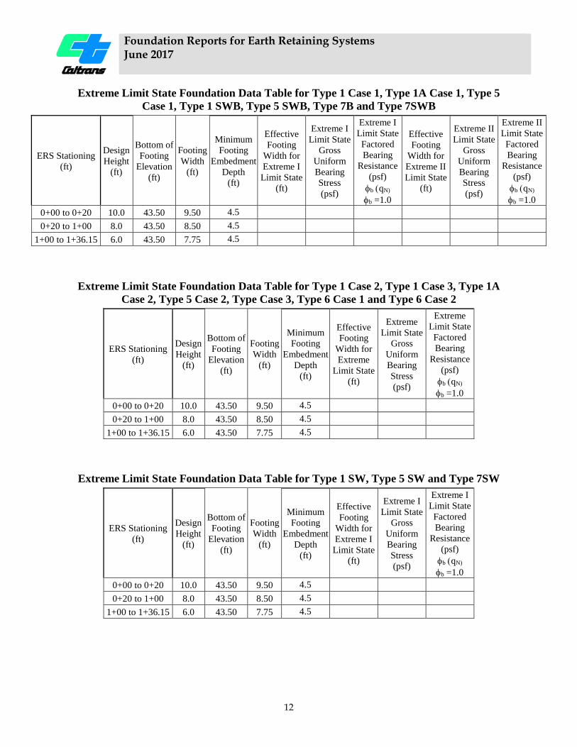
Extreme Limit State Foundation Data Table for Type 1 Case 1, Type 1A Case 1, Type 5 Case 1, Type 1 SWB, Type 5 SWB, Type 7B and Type 7SWB
ERS Stationing (ft)
Design Height
(ft)
Bottom of Footing
Elevation (ft)
Footing Width
(ft)
Minimum Footing
Embedment Depth
(ft)
Effective Footing
Width for Extreme I Limit State
(ft)
Extreme I Limit State
Gross Uniform Bearing Stress (psf)
Extreme I Limit State Factored Bearing
Resistance (psf) φb (qN)
φb =1.0
Effective Footing
Width for Extreme II Limit State
(ft)
Extreme II Limit State
Gross Uniform Bearing Stress (psf)
Extreme II Limit State Factored Bearing
Resistance (psf) φb (qN)
φb =1.0 0+00 to 0+20 10.0 43.50 9.50 4.5 0+20 to 1+00 8.0 43.50 8.50 4.5
1+00 to 1+36.15 6.0 43.50 7.75 4.5
Extreme Limit State Foundation Data Table for Type 1 Case 2, Type 1 Case 3, Type 1A Case 2, Type 5 Case 2, Type Case 3, Type 6 Case 1 and Type 6 Case 2
ERS Stationing (ft)
Design Height
(ft)
Bottom of Footing
Elevation (ft)
Footing Width
(ft)
Minimum Footing
Embedment Depth
(ft)
Effective Footing
Width for Extreme
Limit State (ft)
Extreme Limit State
Gross Uniform Bearing Stress (psf)
Extreme Limit State Factored Bearing
Resistance (psf) φb (qN)
φb =1.0 0+00 to 0+20 10.0 43.50 9.50 4.5 0+20 to 1+00 8.0 43.50 8.50 4.5
1+00 to 1+36.15 6.0 43.50 7.75 4.5
Extreme Limit State Foundation Data Table for Type 1 SW, Type 5 SW and Type 7SW
ERS Stationing (ft)
Design Height
(ft)
Bottom of Footing
Elevation (ft)
Footing Width
(ft)
Minimum Footing
Embedment Depth
(ft)
Effective Footing
Width for Extreme I Limit State
(ft)
Extreme I Limit State
Gross Uniform Bearing Stress (psf)
Extreme I Limit State Factored Bearing
Resistance (psf) φb (qN)
φb =1.0 0+00 to 0+20 10.0 43.50 9.50 4.5 0+20 to 1+00 8.0 43.50 8.50 4.5
1+00 to 1+36.15 6.0 43.50 7.75 4.5
Foundation Reports for Earth Retaining Systems June 2017
13
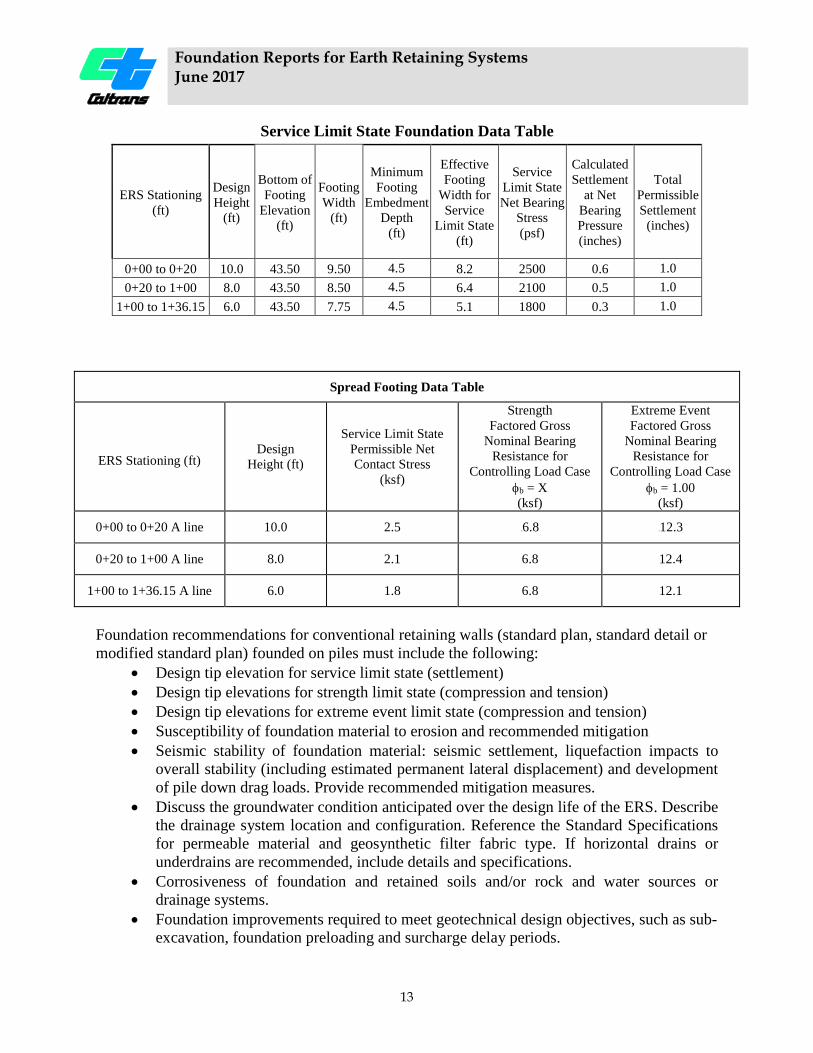
Service Limit State Foundation Data Table
ERS Stationing (ft)
Design Height
(ft)
Bottom of Footing
Elevation (ft)
Footing Width
(ft)
Minimum Footing
Embedment Depth
(ft)
Effective Footing
Width for Service
Limit State (ft)
Service Limit State Net Bearing
Stress (psf)
Calculated Settlement
at Net Bearing Pressure (inches)
Total Permissible Settlement
(inches)
0+00 to 0+20 10.0 43.50 9.50 4.5 8.2 2500 0.6 1.0 0+20 to 1+00 8.0 43.50 8.50 4.5 6.4 2100 0.5 1.0
1+00 to 1+36.15 6.0 43.50 7.75 4.5 5.1 1800 0.3 1.0
Spread Footing Data Table
ERS Stationing (ft) Design
Height (ft)
Service Limit State Permissible Net Contact Stress
(ksf)
Strength Factored Gross
Nominal Bearing Resistance for
Controlling Load Case φb = X (ksf)
Extreme Event Factored Gross
Nominal Bearing Resistance for
Controlling Load Case φb = 1.00
(ksf)
0+00 to 0+20 A line 10.0 2.5 0B6.8 1B12.3
0+20 to 1+00 A line 8.0 2.1 6.8 12.4
1+00 to 1+36.15 A line 6.0 1.8 6.8 12.1
Foundation recommendations for conventional retaining walls (standard plan, standard detail or modified standard plan) founded on piles must include the following:
• Design tip elevation for service limit state (settlement) • Design tip elevations for strength limit state (compression and tension) • Design tip elevations for extreme event limit state (compression and tension) • Susceptibility of foundation material to erosion and recommended mitigation • Seismic stability of foundation material: seismic settlement, liquefaction impacts to
overall stability (including estimated permanent lateral displacement) and development of pile down drag loads. Provide recommended mitigation measures.
• Discuss the groundwater condition anticipated over the design life of the ERS. Describe the drainage system location and configuration. Reference the Standard Specifications for permeable material and geosynthetic filter fabric type. If horizontal drains or underdrains are recommended, include details and specifications.
• Corrosiveness of foundation and retained soils and/or rock and water sources or drainage systems.
• Foundation improvements required to meet geotechnical design objectives, such as sub-excavation, foundation preloading and surcharge delay periods.
Foundation Reports for Earth Retaining Systems June 2017
14
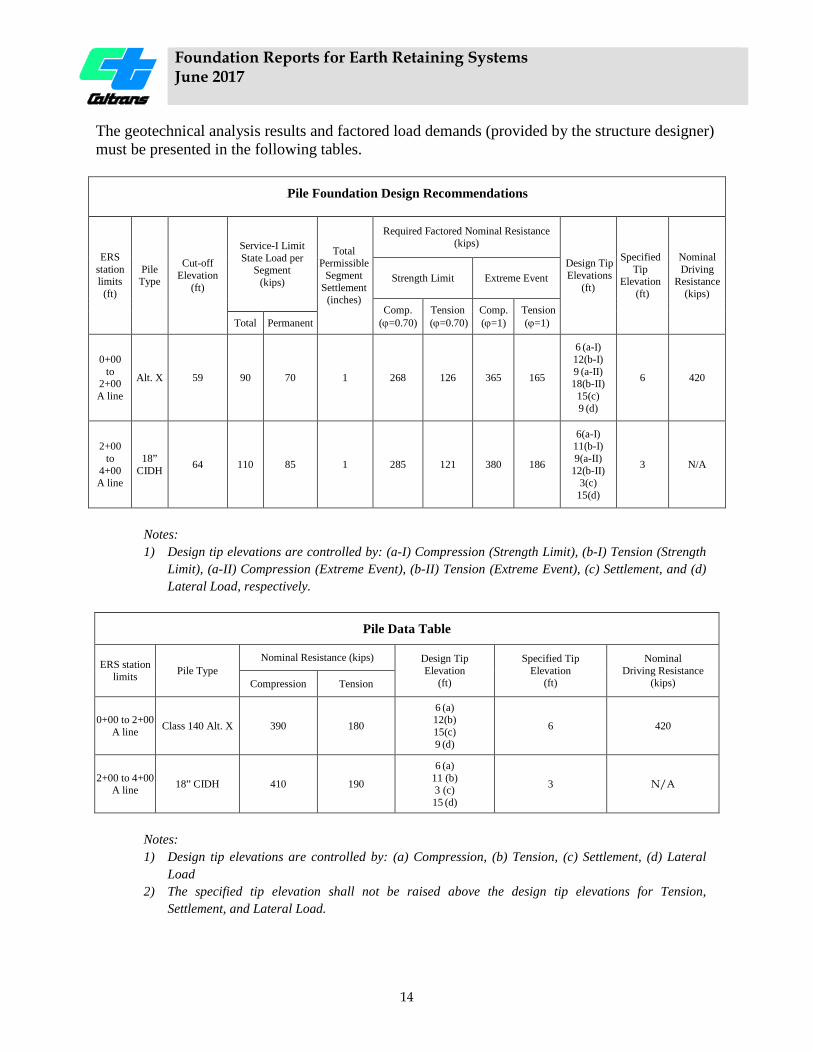
The geotechnical analysis results and factored load demands (provided by the structure designer) must be presented in the following tables.
2BPile Foundation Design Recommendations
ERS station limits
(ft)
Pile Type
Cut-off Elevation
(ft)
Service-I Limit State Load per
Segment
(kips)
Total Permissible
Segment Settlement
(inches)
Required Factored Nominal Resistance (kips)
Design Tip Elevations
(ft)
Specified Tip
Elevation (ft)
Nominal Driving
Resistance (kips)
Strength Limit Extreme Event
Comp. (ϕ=0.70)
Tension (ϕ=0.70)
Comp. (ϕ=1)
Tension (ϕ=1) Total Permanent
0+00 to
2+00 A line
Alt. X 59 90 70 1 268 126 365 165
6 (a-I) 12(b-I) 9 (a-II) 18(b-II)
15(c) 9 (d)
6 420
2+00 to
4+00 A line
18” CIDH 64 110 85 1 285 121 380 186
6(a-I) 11(b-I) 9(a-II)
12(b-II) 3(c)
15(d)
3 N/A
Notes:
1) Design tip elevations are controlled by: (a-I) Compression (Strength Limit), (b-I) Tension (Strength Limit), (a-II) Compression (Extreme Event), (b-II) Tension (Extreme Event), (c) Settlement, and (d) Lateral Load, respectively.
Pile Data Table
ERS station limits Pile Type
Nominal Resistance (kips) Design Tip Elevation
(ft)
Specified Tip Elevation
(ft)
Nominal Driving Resistance
(kips) Compression Tension
0+00 to 2+00 A line Class 140 Alt. X 390 180
6 (a) 12(b) 15(c) 9 (d)
6 420
2+00 to 4+00 A line 18” CIDH 410 190
6 (a) 11 (b) 3 (c) 15 (d)
3 N/A
Notes: 1) Design tip elevations are controlled by: (a) Compression, (b) Tension, (c) Settlement, (d) Lateral
Load 2) The specified tip elevation shall not be raised above the design tip elevations for Tension,
Settlement, and Lateral Load.
Foundation Reports for Earth Retaining Systems June 2017
15
3.12.2.2 Non-gravity Cantilever Systems Non-gravity cantilever systems include sheet pile walls, soldier pile walls with or without lagging, tangent pile walls, and secant pile walls.
Foundation recommendations for non-gravity cantilever retaining systems (soldier pile, secant, and tangent or slurry diaphragm retaining walls) must include the following:
• Soil and/or rock parameters for the internal and structural design (unit weight, friction angle and cohesion for soil, and unit weight and shear strength of the rock mass). This applies to the foundation and retained materials.
• Recommended material models, per AASHTO Bridge Design Specifications Section 3.11.5.6, “Lateral Earth Pressures for Non-gravity Cantilevered Walls”, for developing the lateral earth pressure distribution (active and passive).
• For designs utilizing vertical piles that carry vertical loads, the factored nominal bearing resistance for piles having a specified tip elevation or embedment length
• For designs utilizing soldier piles, recommendation for minimum pile embedment depth and/or pile tip elevations based on global stability or erosion considerations.
• Total and differential settlement in the retained zone as a result of the placement of fills (service limit state) and pile lateral deflection.
• Calculated resistance factor for overall (global) and local stability (service and extreme event limit states). Provide the method of analysis.
• Seismic stability of foundation material: seismic settlement, liquefaction impacts to overall stability (including estimated permanent lateral displacement) and bearing resistance. Provide recommended mitigation measures.
• Recommended arching factors for all soil and rock types in which soldier piles are embedded.
• A recommendation for lagging or wall face embedment below finish grade based on erosion, local stability and global stability considerations.
• Discuss the groundwater condition anticipated over the design life of the ERS. Describe the drainage system location and configuration. Reference the Standard Specifications for permeable material and geosynthetic filter fabric type. If horizontal drains or underdrains are recommended, include details and specifications.
• Corrosiveness of foundation and retained soils and/or rock and water sources or drainage systems.
• Down drag loads on the piles as a result of the addition of overburden pressure. 3.12.2.3 Anchored Pile Systems The anchored systems category includes ground anchored pile systems, anchored diaphragm walls, and soil nail walls.
Ground Anchored Pile Systems Anchored pile systems include a row of drilled vertical soldier piles and sub-horizontal drilled ground anchors installed into an anchorage zone behind the retained soil or rock. Recommendation for anchored pile systems must include:
Foundation Reports for Earth Retaining Systems June 2017
16
• Soil and/or rock parameters for the internal and structural design (unit weight, friction angle and cohesion for soil, and unit weight and shear strength of the rock mass). This applies to the foundation and retained materials.
• Recommended material models, per AASHTO Bridge Design Specifications Section 3.11.5.7, “Apparent Earth Pressure (AEP) for Anchored Walls”, for developing the lateral earth pressure distribution (active and passive).
• For designs utilizing vertical piles that carry vertical loads, the factored nominal bearing resistance for piles having a specified tip elevation or embedment length.
• For designs utilizing soldier piles, recommendation for minimum pile embedment depth and/or pile tip elevations based on global stability or erosion considerations.
• Total and differential settlement in the retained zone as a result of the placement of fills (service limit state) and pile lateral deflection.
• Calculated resistance factor for overall (global) and local stability (service and extreme event limit states). Provide the method of analysis.
• Seismic stability of foundation material: seismic settlement, liquefaction impacts to overall stability (including estimated permanent lateral displacement) and bearing resistance. Provide recommended mitigation measures.
• Recommended arching factors for all soil and rock types in which soldier piles are embedded.
• A recommendation for lagging or wall face embedment below finish grade based on erosion, local stability and global stability considerations.
• Discuss the groundwater condition anticipated over the design life of the ERS. Describe the drainage system location and configuration. Reference the Standard Specifications for permeable material and geosynthetic filter fabric type. If horizontal drains or underdrains are recommended, include details and specifications.
• Corrosiveness of foundation and retained soils and/or rock and water sources or drainage systems.
• The minimum unbonded ground anchor lengths to satisfy static and seismic overall stability (consider providing in tabular format)
• Recommended ground anchor inclination. • For ERS constructed to retain slope failures, provide the total required earth retention
force and the associated global stability resistance factor. • Recommended location of ground anchors subject to performance testing. • Down drag loads on the piles as a result of the addition of overburden pressure.
Anchored Diaphragm Walls Anchored diaphragm walls utilize a reinforced concrete diaphragm as the facing with no pile foundation. The facing typically bears on foundation soil, embedded below a toe bench. Recommendations for anchored diaphragm wills must include:
• Soil and/or rock parameters for the internal and structural design (unit weight, friction angle and cohesion for soil, and unit weight and shear strength of the rock mass). This applies to the foundation and retained materials.
• Total and differential settlement in the retained zone as a result of the placement of fills (service limit state) and wall lateral deflection.
Foundation Reports for Earth Retaining Systems June 2017
17
• Calculated resistance factor for overall (global) and local stability (service and extreme event limit states). Provide the method of analysis.
• Seismic stability of foundation material: seismic settlement, liquefaction impacts to overall stability (including estimated permanent lateral displacement) and bearing resistance. Provide recommended mitigation measures.
• A recommendation for lagging or wall face embedment below finish grade based on erosion, local stability and global stability considerations.
• Discuss the groundwater condition anticipated over the design life of the ERS. Describe the drainage system location and configuration. Reference the Standard Specifications for permeable material and geosynthetic filter fabric type. If horizontal drains or underdrains are recommended, include details and specifications.
• Corrosiveness of foundation and retained soils and/or rock and water sources or drainage systems.
• The minimum unbonded ground anchor lengths to satisfy static and seismic overall stability (consider providing in tabular format)
• Recommended ground anchor inclination. • For ERS constructed to retain slope failures, provide the total required earth retention
force and the associated global stability resistance factor. • Recommended location of ground anchors subject to performance testing. • Down drag loads on the wall elements as a result of the addition of overburden
pressure.
Soil Nail Walls Soil Nail Wall recommendations must be reported in accordance with this document and the Soil Nail Wall module of the Geotechnical Manual. 3.12.2.4 Mechanically Stabilized Embankment (MSE) Caltrans pre-designed MSE recommendations must be reported in accordance with this document and the Mechanically Stabilized Embankment (Caltrans Pre-Designed) module of the Geotechnical Manual.
MSE utilizing geosynthetic reinforcement are typically designed by Geotechnical Services. The geotechnical designer determines the wall geometry and details. Foundation recommendations for MSE with geosynthetic reinforcement must include all of the requirements for MSE with metallic reinforcement, and the following:
• Cross sections and MSE profile showing the geosynthetic reinforcement types and placement (spacing): lengths, elevations, station limits, and top and bottom elevations of the ERS
• Wall batter • List of reinforcement types and the required Long Term Design Strengths (LTDS) • Active earth pressure coefficient (ka) and passive earth pressure coefficient (kp) • Analysis of base sliding • Wall face material, batter and stability
Foundation Reports for Earth Retaining Systems June 2017
18
• Wall face to reinforcement connection detail
3.12.2.5 Prefabricated Modular Walls Prefabricated modular wall types typically used by Caltrans include crib walls, gabion walls, and mortarless concrete block gravity walls. Typically crib walls utilize a geometry shown in the Caltrans Standard Plans. Geotechnical Services typically determines the geometry and detailing of gabion walls and mortarless concrete block walls. Foundation recommendations for all types of Prefabricated Modular Walls must include the following:
• Soil and/or rock parameters for the internal and structural design (unit weight, friction angle and cohesion for soil, and unit weight and shear strength of the rock mass). This applies to the foundation and retained materials.
• Factored gross nominal bearing resistances (strength and extreme event limit states) • Total and differential settlement as a result of application of the net bearing pressure
(service limit state). Differential settlement should be examined both along the alignment of the wall face and between the front and back of the system. Effects of ERS construction on adjacent ground and/or existing structures, utilities and other structures, both above and below ground.
• Permissible net contact stress (service limit state) • Calculated resistance factor for overall (global) and local stability (service and extreme
event limit states). Provide the method of analysis. • Seismic stability of foundation material: seismic settlement, liquefaction impacts to
overall stability (including estimated permanent lateral displacement) and bearing resistance. Provide recommended mitigation measures.
• Foundation improvements required to meet geotechnical design objectives, such as sub-excavation, foundation preloading and surcharge delay periods.
• The minimum embedment depth of the prefabricated modular wall and toe bench width based on erosion, overall stability, bearing resistance and settlement analyses.
• Minimum base width to meet overall stability requirements • Discuss the groundwater condition anticipated over the design life of the ERS, and if a
blanket drain is required. Describe the drainage system location and configuration. Reference the Standard Specifications for permeable material and geosynthetic filter fabric type.
• Slope or batter of the face used in slope modeling, grades and slopes analyzed. • Corrosiveness of foundation and retained soils and/or rock and water sources or
drainage systems. • Foundation improvements required to meet geotechnical design objectives, such as sub-
excavation, foundation preloading and surcharge delay periods. • Type of crib or configuration of the gabions (such as stepped front, or smooth front and
stepped rear). • Infill considerations, or facing closure recommendations • Indicate the weight of the mature landscaping included in the ERS modeling and
stability calculations.

Foundation Reports for Earth Retaining Systems June 2017
19
Foundation recommendations for Geotechnical Services designed gabion and mortarless concrete block walls include all those listed above for prefabricated modular walls, and the following:
• Cross sections showing wall geometry. For gabion walls this includes the thickness and number of baskets, the basket dimensions and the size of the rock infill.
• Wall batter • Analysis of base sliding • Active earth pressure coefficient (ka) and passive earth pressure coefficient (kp) • Maximum external loading • Design criteria for the General notes on the contract plans • Information for estimating purposes • Specifications requirements/additions including manufacturers information when
necessary 3.12.2.6 Other ERS Technologies Reports for ERS not previously discussed should include applicable topics listed for any of the ERS discussed here, as well as additional ERS specific information necessary to prepare a design that is in compliance with LRFD specifications. 3.13 Notes to Designer Include a discussion of geotechnical issues incidental to the ERS design:
• Temporary slope treatment • Need for temporary shoring or temporary cut slope angles as a result of right of way or
environmental constraints • Excavation limits • ERS termination details • Suitability of the in-situ soils as backfill • Rock rippability • Specifications for backfill • Requirements to remove buried objects or structures
3.14 Construction Considerations Construction considerations are specific notes intended for the State's specification engineers, estimators, construction personnel and contractors. Construction considerations identify relevant Standard Specifications and important design criteria that were used in the geotechnical design of the retaining system. Construction considerations should identify conditions that will be encountered in the field during construction. Specific notes regarding the site geology should be included within the construction considerations section to ensure that both the intent of the geotechnical design is met and construction of the ERS is successful. Do not refer to or quote the Standard Specifications.
Address additional topics when applicable, such as:
Foundation Reports for Earth Retaining Systems June 2017
20
• Groundwater and seepage • Temporary excavations • Slope stability • Settlement monitoring • Staging • Dewatering requirements • Caving conditions • Presence of voids • Presence of cobbles and boulders, or man-made buried objects • Presences of fractured rock, weathered rock, very hard rock or variable rock conditions • Effects of construction work on adjacent structures. • Recommended on-site training of construction personnel by GS staff. • Recommended construction inspection to be performed by Geotechnical Services
personnel • Requirement for, and methods of pre/post-construction surveys, monitoring during
construction, and documentation of adjacent ground and/or facilities (survey markers or slope inclinometers)
• Discuss pile set-up period requirements, by pile location. • Requirement to isolate piles from adjacent settling soil. • Requirement for pile or micropile load test, compression or tension. Provide Factored
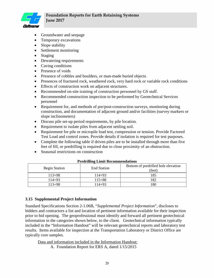
Test Load and control zones. Provide details if isolation is required for test purposes. • Complete the following table if driven piles are to be installed through more than five
feet of fill, or predrilling is required due to close proximity of an obstruction. • Seasonal restrictions on construction
Predrilling Limit Recommendations
Begin Station End Station Bottom of predrilled hole elevation (feet)
113+98 114+93 185 114+93 115+88 182 113+98 114+93 180
3.15 Supplemental Project Information Standard Specifications Section 2-1.06B, “Supplemental Project Information”, discloses to bidders and contractors a list and location of pertinent information available for their inspection prior to bid opening. The geoprofessional must identify and forward all pertinent geotechnical information in the categories shown below, to the client. Geotechnical information typically included in the “Information Handout” will be relevant geotechnical reports and laboratory test results. Items available for inspection at the Transportation Laboratory or District Office are typically core samples.
Data and information included in the Information Handout: A. Foundation Report for ERS A, dated 1/15/2015
Foundation Reports for Earth Retaining Systems June 2017
21
B. Geophysical Report for ERS A, dated 1/10/2015 C. Laboratory Test Data for ERS A
Data and information included with the project plans are: A. Log of Test Borings for ERS A
Data and information available for inspection at the Translab: A. Core Samples.
Data and information available for inspection at the District Office: A. None.
All pertinent information to be included in the Supplemental Project Information must be sent to the client in PDF format via electronic mail. 3.16 Appendices The Foundation Report appendices provide detailed information supporting the retaining wall type selection, analyses, recommendations, and construction considerations. These must contain at least the following, if applicable:
3.16.1 Appendix I: Field Exploration and Testing Data acquired from field exploration and testing such as surface geologic mapping and surface geophysical survey, Pressuremeter, Dilatometer, and in-situ Vane Shear Tests, Borehole Geophysical logging, indicator pile tests, Piezometer Readings, etc.
3.16.2 Appendix II: Laboratory Test Results 1. Soil and rock laboratory test results. 2. Corrosion test results.
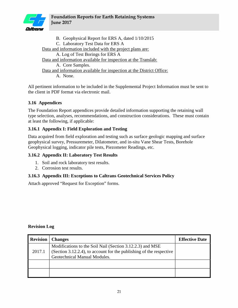
3.16.3 Appendix III: Exceptions to Caltrans Geotechnical Services Policy Attach approved “Request for Exception” forms. Revision Log Revision Changes Effective Date
2017.1 Modifications to the Soil Nail (Section 3.12.2.3) and MSE (Section 3.12.2.4), to account for the publishing of the respective Geotechnical Manual Modules.

Foundation Reports for Earth Retaining Systems June 2017
22