Embed Size (px)
Citation preview
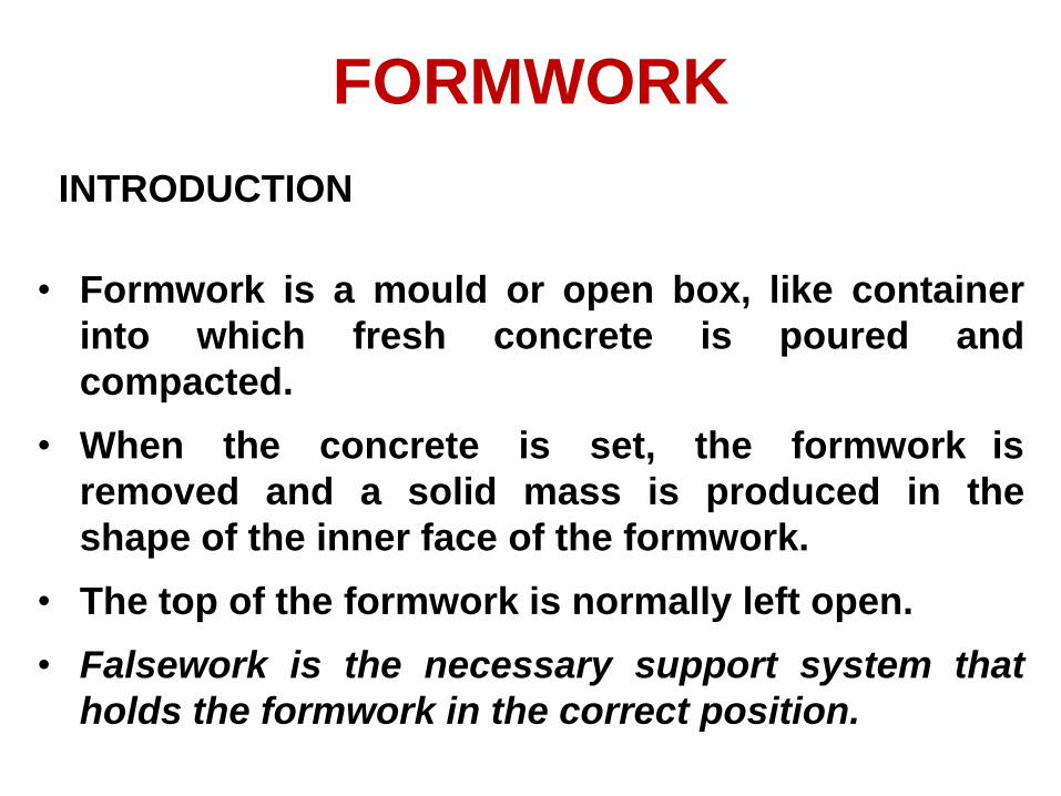
FORMWORK
INTRODUCTION
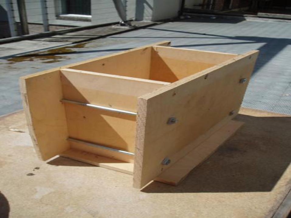
• Formwork is a mould or open box, like container
into which fresh concrete is poured and
compacted.
• When the concrete is set, the formwork is
removed and a solid mass is produced in the
shape of the inner face of the formwork.
• The top of the formwork is normally left open.
• Falsework is the necessary support system that
holds the formwork in the correct position.
FORMWORK FOR CONCRETE
STRUCTURES SHOULD BE 1. Strong enough to resist the pressure or the
weight of the fresh concrete plus any
constructional live loads.
2. Rigid enough to retain the shape without
undue deformation.
3. Economical in terms of the total cost of the
forms and the concrete surface finishing
when required.
4. Sufficiently watertight to avoid leakage at
the joints.
FORMWORK ECONOMY
In order to reduce the cost of formwork for
concrete structures the following are to be
considered:
1. Design the formwork to provide adequate but
not excessive strength and rigidity.
2. Fabricate the forms into modular sizes to
provide more reuses without refabricating
when practical.
3. Prepare working drawings prior to fabricating
the forms.
4. Prefabricate form sections on the ground
rather than on scaffolding.
FORMWORK ECONOMY (continued)
5. Use the most economical formwork
material considering the initial cost and
reuses.
6. Use no more nails than are needed to join the
forms together safely.
7. Remove the formwork as soon as it is
permissible.
8. Clean and oil forms by using releasing agent
after each use.
9. When it is permissible install construction
joins to reduce the total quantity of form
material required and permit the carpenters
to work more continuously.

FORMWORK MATERIALS
Formwork materials can be classified as:
1. Timber
2. Metals
3. Plastics
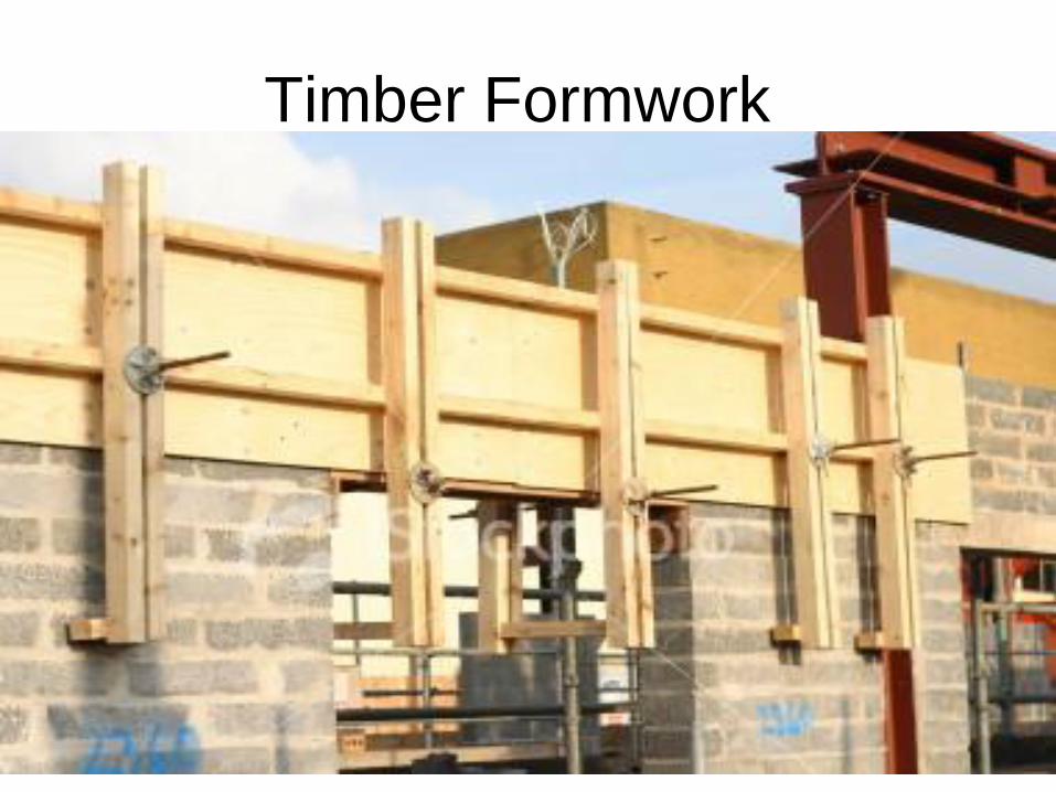
Timber Formwork
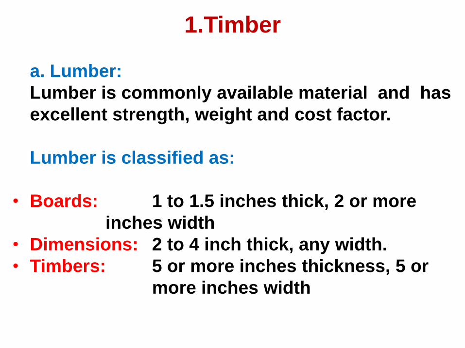
1.Timber
a. Lumber:
Lumber is commonly available material and has
excellent strength, weight and cost factor.
Lumber is classified as:
• Boards: 1 to 1.5 inches thick, 2 or more
inches width
• Dimensions: 2 to 4 inch thick, any width.
• Timbers: 5 or more inches thickness, 5 or
more inches width
b. Plywood
• The use of plywood in concrete forming for
form facing has improved the quality of
finished concrete.
• The relatively large sheets of plywood have
reduced the cost of building and at the same
time have provided smooth surfaces that
reduces cost of finishing of concrete surfaces.
• PIywood is a manufactured wood product
consisting a number of veneer sheets, or plies
• Type of plywood can be grouped as exterior
and interior. For formwork the exterior plywood
is used. Adhesive used to bond the piles in
manufacturing of exterior plywood is watertight
and gives maximum number of reuses.
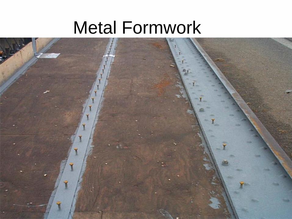
Metal Formwork
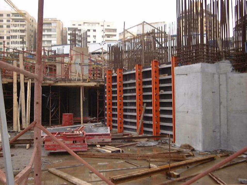
2. Metals
• The initial cost of metal formwork is more
than timber formwork but the ııumber of
reuses of metal formwork is higher than that
of timber.
• in long run metal formwork can be
economical.
• İn heavy construction works metal
formvvork may require a lifting mechanism
to handle the formvvork panels or props.
• Steel sheet formvvork has the problem of
rusting also. To avoid rusting, in every use the
surfaces should be oiled with an appropriate
releasing agent.
• in metal formvvork usage, the metal sheets
are prepared as panels of standard sizes. This
brings the difficulties of erecting irregular
dimensions of formvvork.
• Steel or aluminum or magnesium is the most
widely used metals.
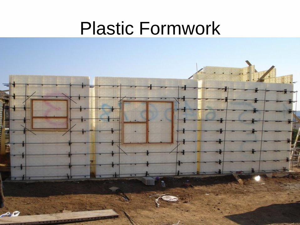
Plastic Formwork
3. Plastics
• They have impervious surfaces that usually create a
smooth fınish to the concrete.
• Plastic formwork could be reinforced or un-
reinforced.
• Plastic is reinforced by glass fibers.
• Reinforced plastics are specially produced for a
specific formvvork type.
• Un-reinforced plastics are produced in sheet form
with smooth or textured surfaces.
• Plastic formwork is lighter but less durable than
metal formvvork.
FORMWORK TYPES (BY SHAPE)
Considering shapes, forımvork types
can be classified as:
• Column Formwork
• Beam formwork
• Slab F6rmwork
• Wall Formwork
Column Formwork
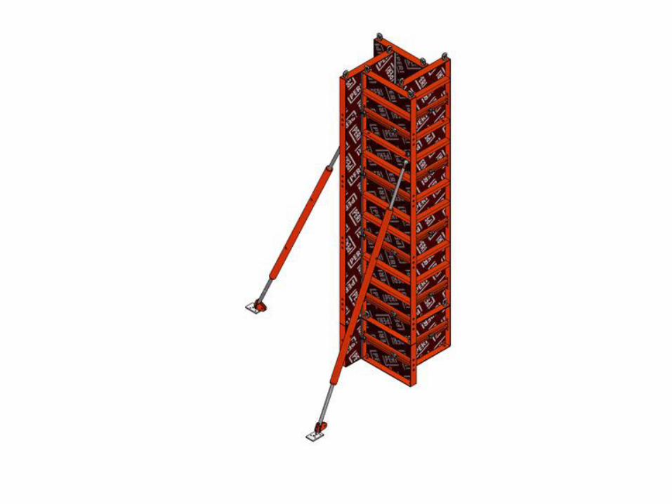
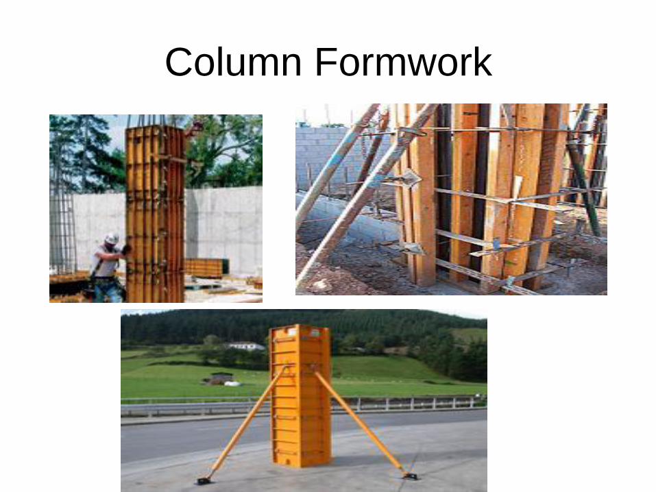
Column Formwork
• Column formwork is made usually with either
timber or metal panels.
• The principle is to create an enclosed box with
frames at the exact size of the column and fix it
tightly on the kicker left from base or at the last
stage of column concreting.
• The box is held in position by steel column
clamps or bolted yokes and supported by
timber studs or props
Beam Formwork
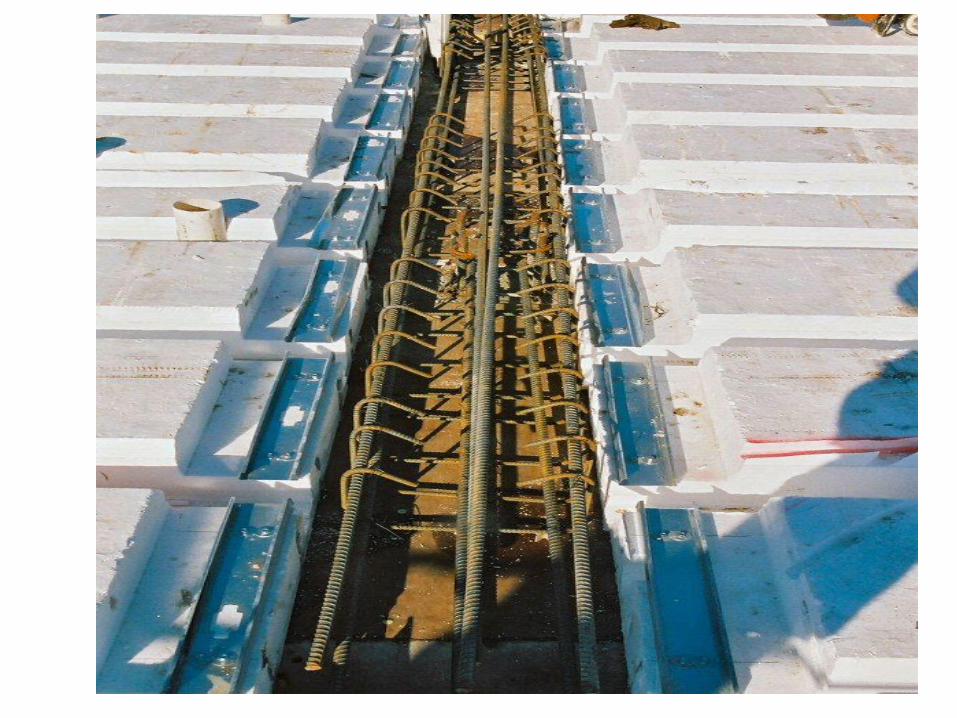
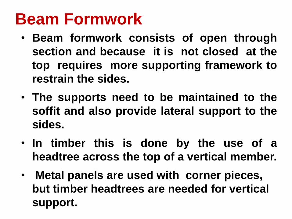
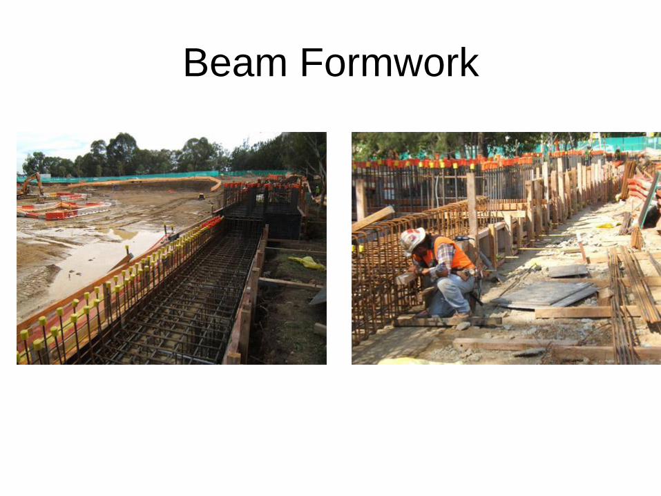
Beam Formwork • Beam formwork consists of open through
section and because it is not closed at the
top requires more supporting framework to
restrain the sides.
• The supports need to be maintained to the
soffit and also provide lateral support to the
sides.
• In timber this is done by the use of a
headtree across the top of a vertical member.
• Metal panels are used with corner pieces,
but timber headtrees are needed for vertical
support.
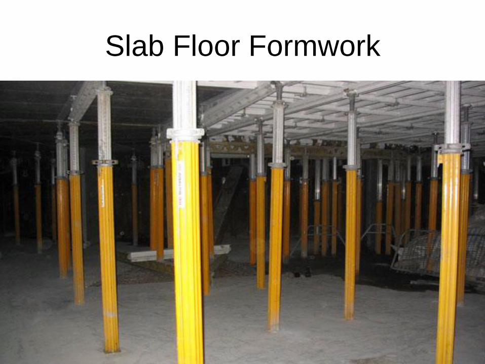
Slab Floor Formwork
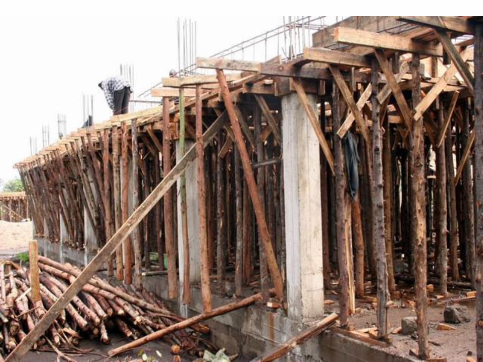
Slab Formwork • Floors require a large area of formwork to be
provided usually fronı beam to beam.
• Timber floor formwork consists of timber
boards or plyvvooıİ sheets supported on a
fraınework and resting on a series of timber
joists.
• Again timber and metal props can be used for
vertical supports.
• Metal panels can be used and bolted or clipped
togetherand held in place by a system of metal
beams or a tabular scaffold system.
• Adjustable props need for levelling purposes
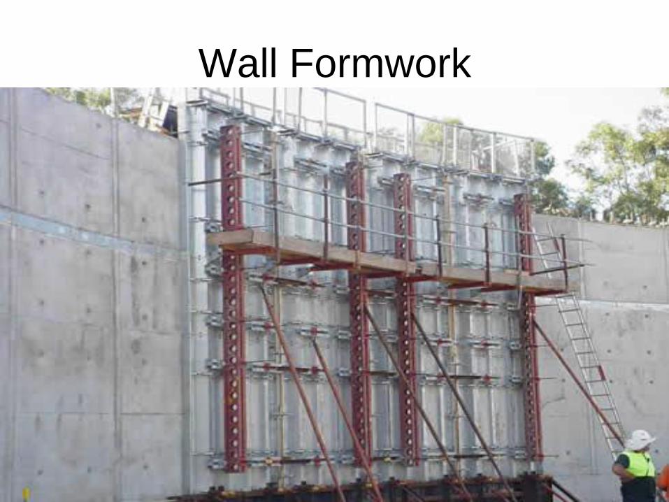
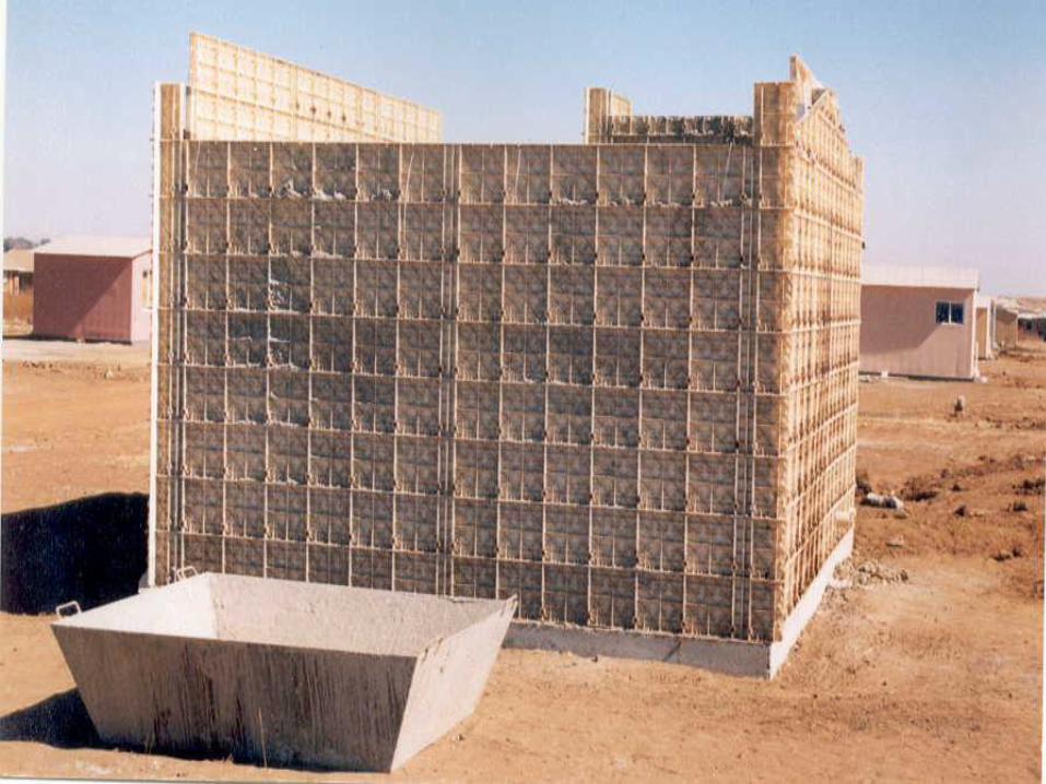
Wall Formwork
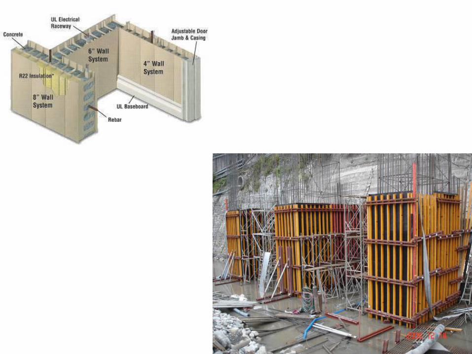
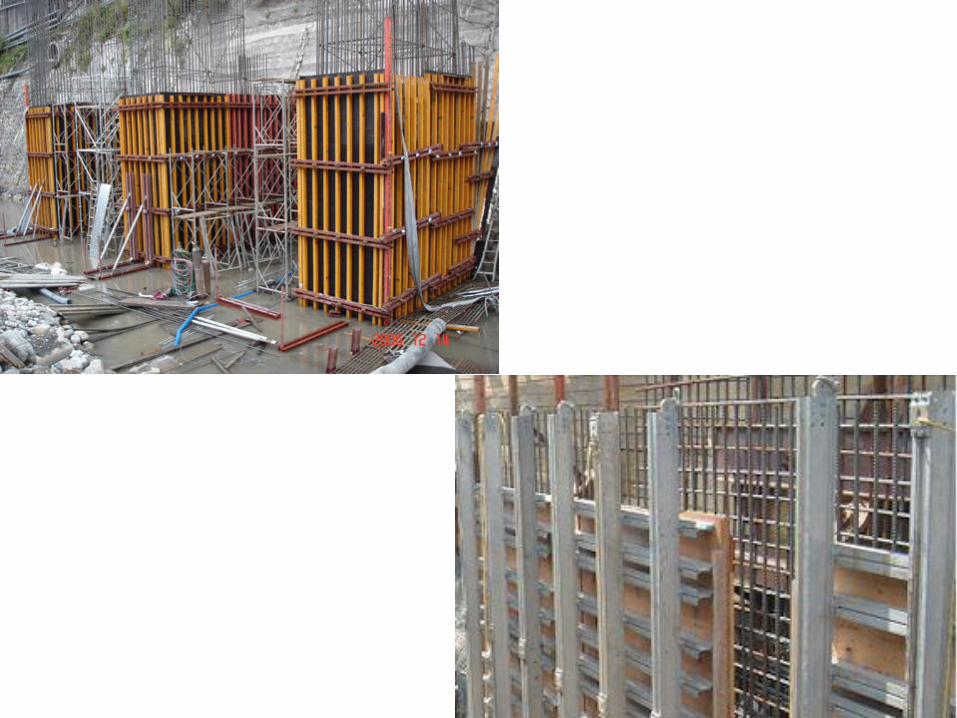
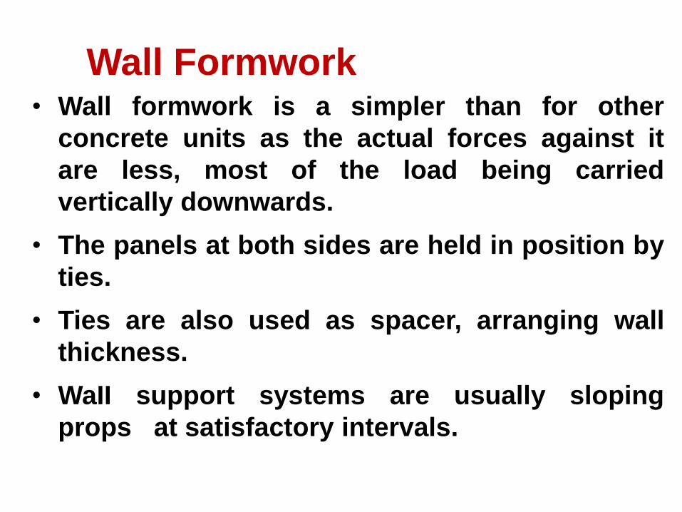
Wall Formwork • Wall formwork is a simpler than for other
concrete units as the actual forces against it
are less, most of the load being carried
vertically downwards.
• The panels at both sides are held in position by
ties.
• Ties are also used as spacer, arranging wall
thickness.
• WaII support systems are usually sloping
props at satisfactory intervals.
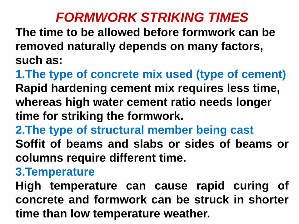
FORMWORK STRIKING TIMES The time to be allowed before formwork can be
removed naturally depends on many factors,
such as:
1.The type of concrete mix used (type of cement)
Rapid hardening cement mix requires less time,
whereas high water cement ratio needs longer
time for striking the formwork.
2.The type of structural member being cast
Soffit of beams and slabs or sides of beams or
columns require different time.
3.Temperature
High temperature can cause rapid curing of
concrete and formwork can be struck in shorter
time than low temperature weather.
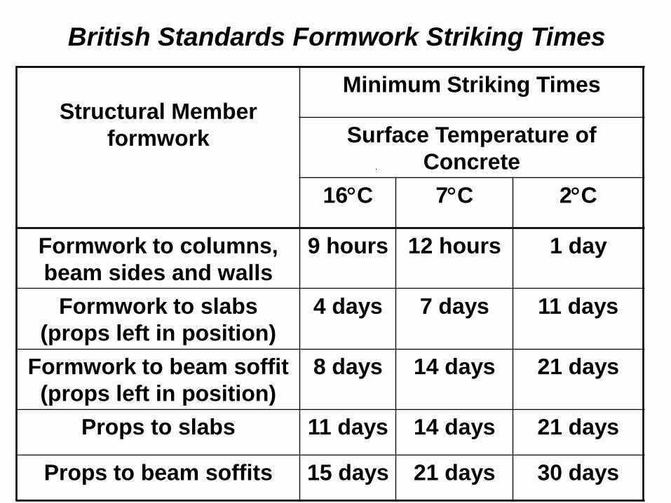
British Standards Formwork Striking Times
Structural Member
formwork
Minimum Striking Times
Surface Temperature of
Concrete
16C 7C 2C
Formwork to columns,
beam sides and walls
9 hours 12 hours 1 day
Formwork to slabs
(props left in position)
4 days 7 days 11 days
Formwork to beam soffit
(props left in position)
8 days 14 days 21 days
Props to slabs 11 days 14 days 21 days
Props to beam soffits 15 days 21 days 30 days
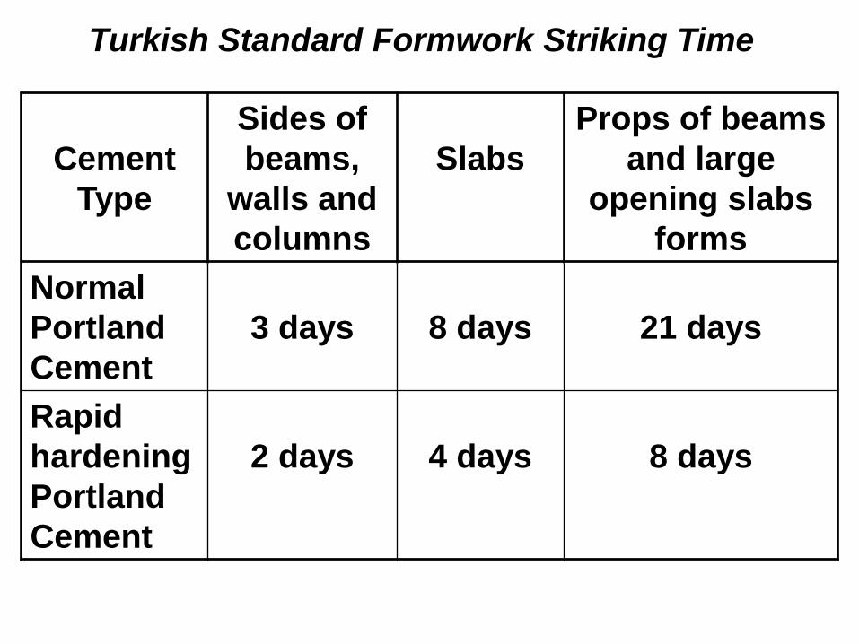
Turkish Standard Formwork Striking Time
Cement
Type
Sides of
beams,
walls and
columns
Slabs
Props of beams
and large
opening slabs
forms
Normal
Portland
Cement
3 days
8 days
21 days
Rapid
hardening
Portland
Cement
2 days
4 days
8 days
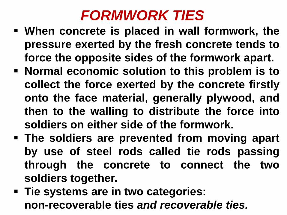
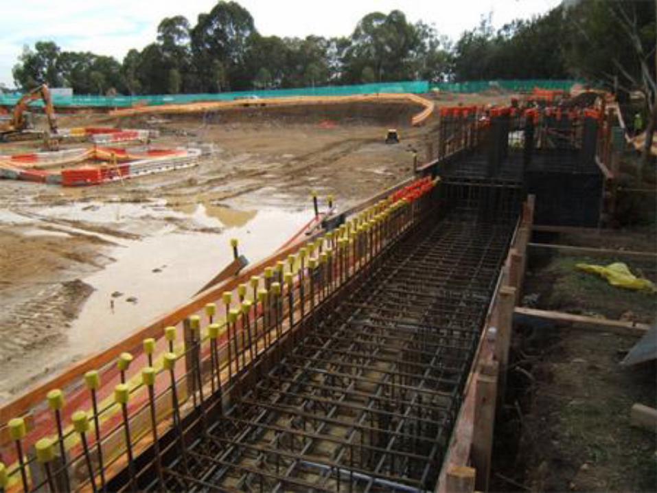
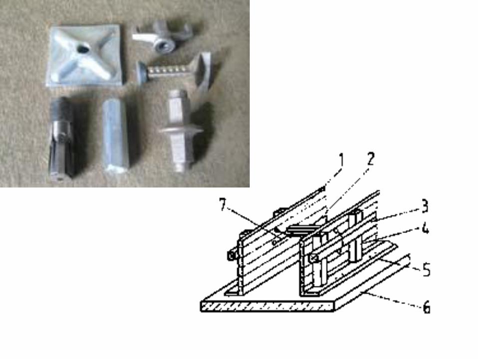
FORMWORK TIES When concrete is placed in wall formwork, the
pressure exerted by the fresh concrete tends to
force the opposite sides of the formwork apart.
Normal economic solution to this problem is to
collect the force exerted by the concrete firstly
onto the face material, generally plywood, and
then to the walling to distribute the force into
soldiers on either side of the formwork.
The soldiers are prevented from moving apart
by use of steel rods called tie rods passing
through the concrete to connect the two
soldiers together.
Tie systems are in two categories:
non-recoverable ties and recoverable ties.
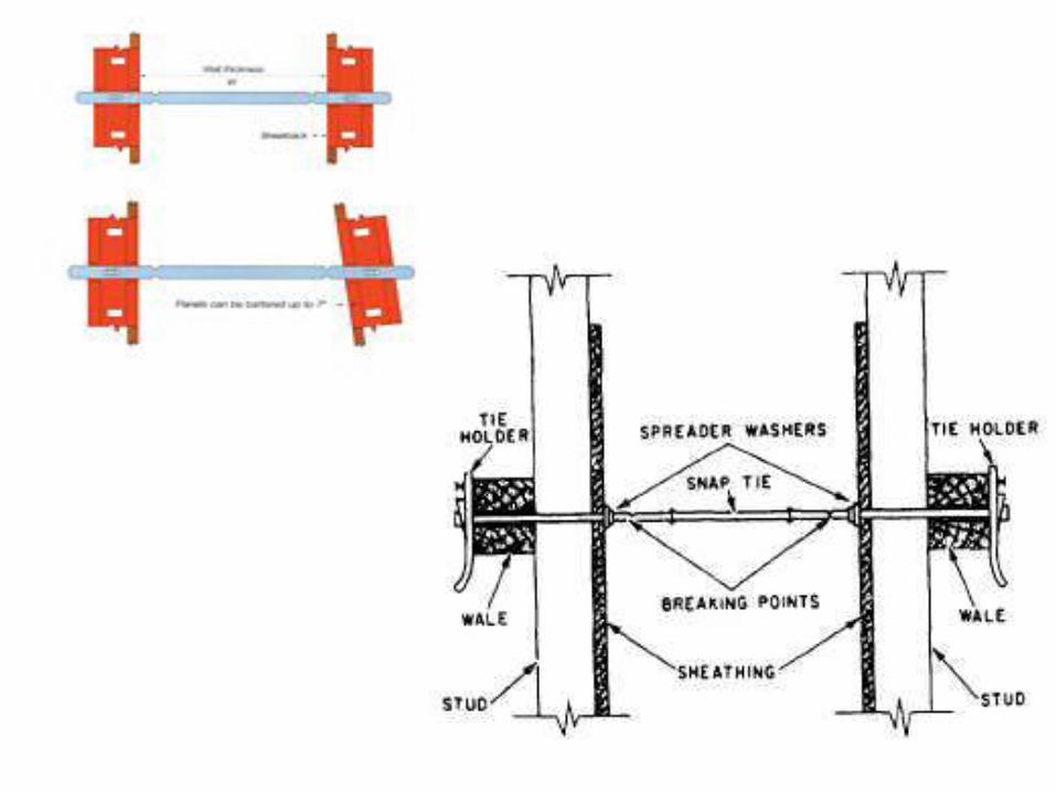
Non-recoverable ties 1. Snap ties The principal of snap ties is that it is cast into
the wall and has normal wedge connection at
each and for fixing to the formwork.
Once the wall is concreted and the formwork
is ready for removal the snap tie is then
physically over-stressed and the ends "snap"
generally inside the concrete.
The snap tie arrangement also acts as a
spacer to the formwork so that ordering the
right length of snap tie automatically gives
the correct wall thickness.
Essentially these ties are used in building
works on strip and re-erect type of fomwork.
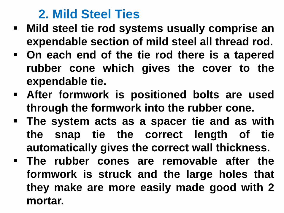
2. Mild Steel Ties Mild steel tie rod systems usually comprise an
expendable section of mild steel all thread rod.
On each end of the tie rod there is a tapered
rubber cone which gives the cover to the
expendable tie.
After formwork is positioned bolts are used
through the formwork into the rubber cone.
The system acts as a spacer tie and as with
the snap tie the correct length of tie
automatically gives the correct wall thickness.
The rubber cones are removable after the
formwork is struck and the large holes that
they make are more easily made good with 2
mortar.
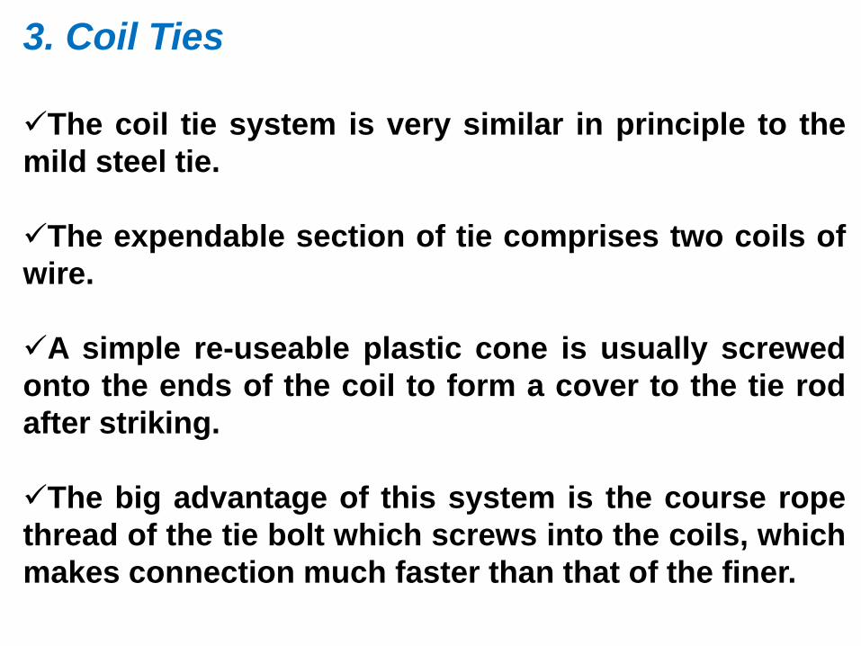
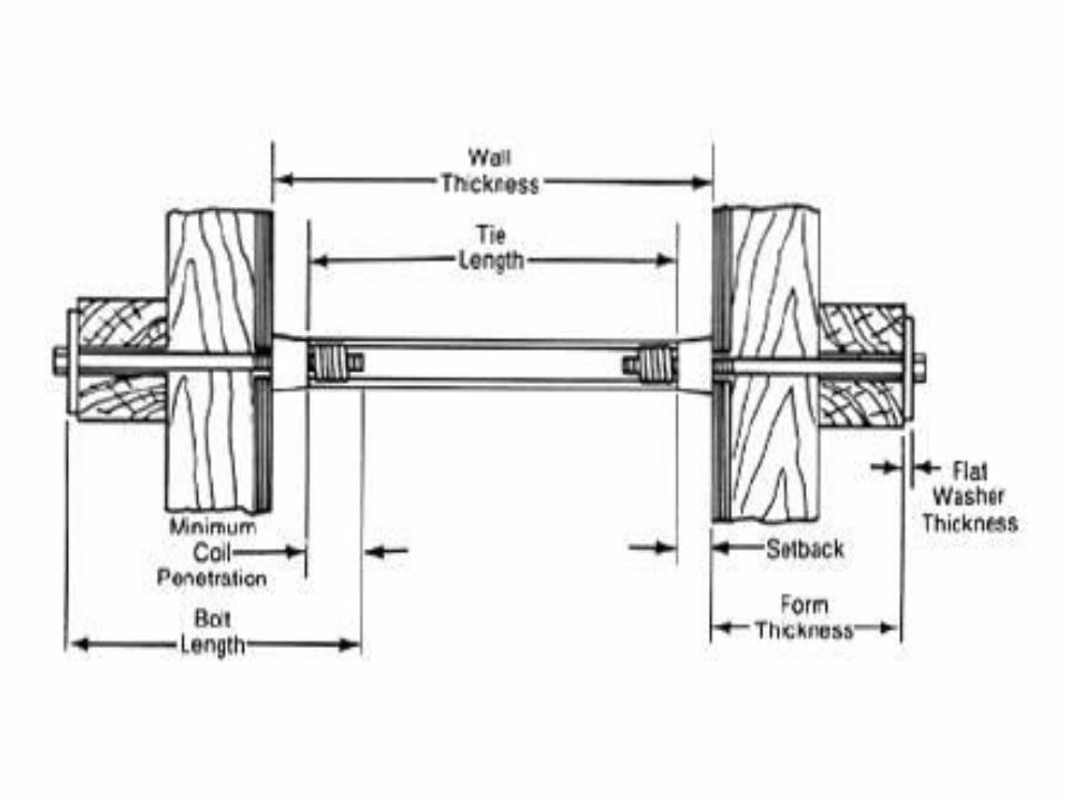
3. Coil Ties
The coil tie system is very similar in principle to the
mild steel tie.
The expendable section of tie comprises two coils of
wire.
A simple re-useable plastic cone is usually screwed
onto the ends of the coil to form a cover to the tie rod
after striking.
The big advantage of this system is the course rope
thread of the tie bolt which screws into the coils, which
makes connection much faster than that of the finer.
4. High Tensile Ties
The H.T. ties rod system comprises a tie rod
which is left in the concrete and is connected
to a re-useable she-bolt.
The big advantage of the H.T. tie system is
that the entire she-bolt, tie rod and other she-
bolt is passed through both faces of
formwork after the forms have been erected.
Large waler plates are then fitted to the ends
of the she-bolts to transfer the high loads into
the soldiers or wailings.
The she-bolt normally has a taper in the
concrete end to allow easy removal once the
concrete has gained strength.
To prevent the tie rod rotating in the green
concrete there is usually either a crimp or a
deformation in the rod.
The H.T. tie system does not act as a spacer
to the wall and separate provision needs to be
made for obtaining the correct thickness of
wall such as a kicker at the base and a spacer
at the top of the form.
2. Recoverable Ties After concrete is placed the ties are removed
and a hole is left behind of it. It is not good in
water reatining structures.
Types of recoverable ties are as follows.
1.Through Ties
The bar generally of 15 mm nominal diameter
is passed right through the wall and uses an
expendable plastic tube with cones at each
end as a spacer through the wall.
The cone is knocked out from one side of the
wall after the formvvork is removed.
The larger hole left in the wall by the cone
needs filling either with a pre-cast concrete
cone or a filler of some sort.
2. Taper Ties
The variation of the through tie without a
sleeve requirement is to have a machined bar
which tapers from one end to the other end.
This is passed through the formwork.
The tie is removed by tapping it through the
wall after use.
3. Anchor Ties
Cast in hook bolts, anchors, loops and fıxings
to form bedded in ties are generally known as
anchor ties.
They are often designed to take both tensile
and shear loading and will be used for
single face climbing formwork.
The loading often depends on the strength
of the concrete in which they are embedded
3.1 Loops
Generally loops are used with coil ties
3.2 ‘ L’Bolts
The use of 'L' bolts cast into the concrete
can form satisfactory anchors.
The type of connection to the formwork will
be similar to the tie system generally used.
The failure of "L' bolts is either due to the
shearing of a cone of concrete from behind
the ‘L' shape or alternatively by the bar
straighting and pulling out of the wall.
The minimum concrete strength for this
being 14 N per mm2.
3.3 Tail Anchors
The tail anchor normally is a H.T. tie with a
bend in the end which is cast into the concrete
and connected to formwork with a she-bolt as
given above.
The tail anchor gives a much deeper
connection of the tie force into the wall and
can only be used on thick walls.
Typical loads for a 1/2" tail anchor are 60 kN
again with minimum concrete strength of 114 N
per mm2.
3.4. Anchor Screws
The anchor screw is a type of machined
course threaded cone which is inserted
into concrete and with a special type of
extractor can be withdrawn after use.
They are used for handling large pre-cast
units and rely upon tensile forces in the
concrete for their load capacity.
The anchor screw is coated with a grease,
which allows the screw to be removed after
use.
3.5. Resin Anchors A new development in providing fixing into
walls for climbing formwork is to use resin
anchors.
These comprise a hole drilled previously
and then filled with a resin capsule which is
then broken and mixed inside the hole.
This resin sets and leaves a projecting bar
from the existing concrete. ttis then
possible to connect onto this bar with a
coupling, any form of tie rod provided the
threads are compatible.
Very often the resin anchors are stronger
than the steel. As with all types of anchors
the concrete strength is to be checked.
3.6. Hanger Ties
Where soffıt formwork is suspended from
beams by hanger ties a load factor of at
least 3 should be used.
The hanger ties should fit as tightly as
possible on the top flange of the beam so
that the eccentricity caused by bending is
reduced to a minimum.
Design of Wall and Column 1. The Maximum Lateral pressure against the
sheathing is determined from the appropriate
equation.
2. If the sheathing thickness has been specified,
the maximum allowable span for the sheathing
based on bending, shear and deflection is the
maximum stud spacing
3. If the stud spacing is fixed, calculate the
required thickness of sheathing
4. Calculate the maximum allowable stud span
“ Wale Spacing” based on stud size and design
load, again considering bending, shear and
deflection.
Design of Wall and Column (continued)
5. If the stud span has already been determined,
calculate the required size of the stud.
6. Determine the maximum allowable spacing of
wale supports “Tie Spacing” based on wale
size and load. . If the tie spacing has been pre
selected, determine the minimum wale size.
8. Check the tie’s ability to carry the load
imposed by wale and tie spacing the load {W}
on each tie is calculated as the design load
{KPa}*the spacing {m}*wale spacing {m}.
Note: If the load exceeds the strength, a stronger
tie must be used or the spacing must be
reduced.
Design of Wall and Column (continued)
9. Check bearing stresses “compression
perpendicular to the grain” where the studs
rest on Wales and where tie ends bear on
Wales.
Note: Maximum bearing stress must not exceed
the allowable compression stress
perpendicular to the grain or crushing will
result.
10. Design lateral bracing to resist any expected
lateral loads, such as wind loads.
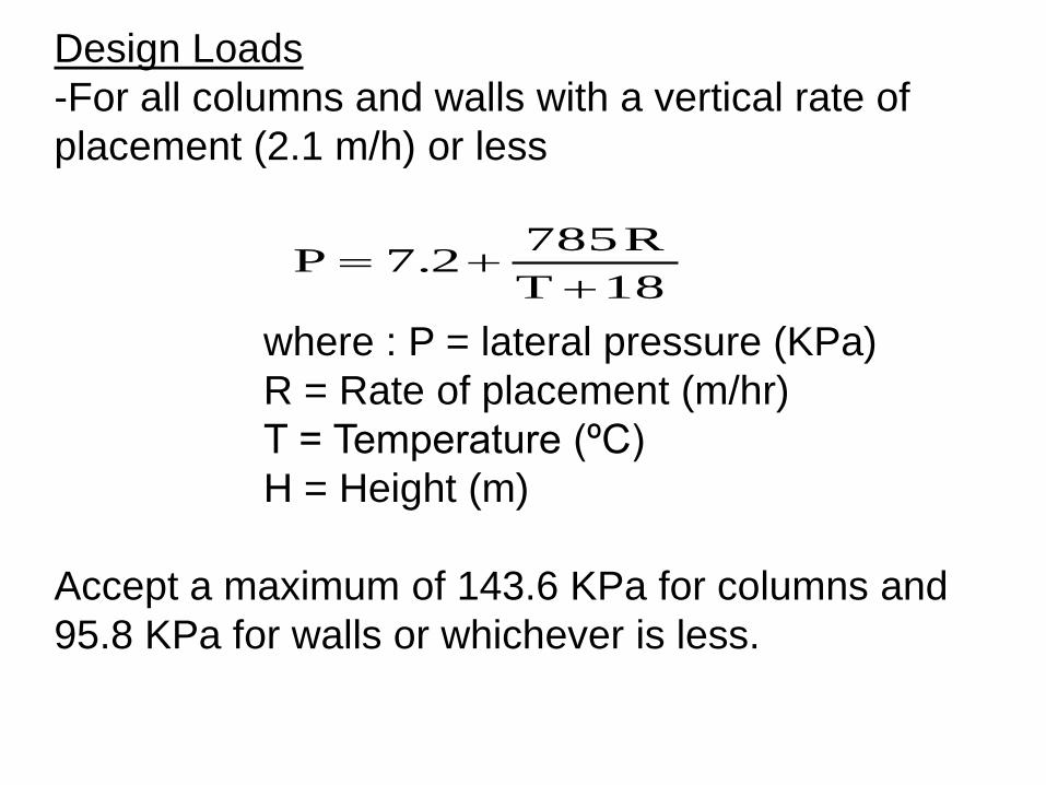
Design Loads
-For all columns and walls with a vertical rate of
placement (2.1 m/h) or less
where : P = lateral pressure (KPa)
R = Rate of placement (m/hr)
T = Temperature (ºC)
H = Height (m)
Accept a maximum of 143.6 KPa for columns and
95.8 KPa for walls or whichever is less.
18 T
R 7857.2P
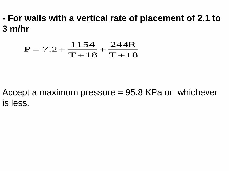
- For walls with a vertical rate of placement of 2.1 to
3 m/hr
18T
R244
18T
11547.2P
Accept a maximum pressure = 95.8 KPa or whichever
is less.
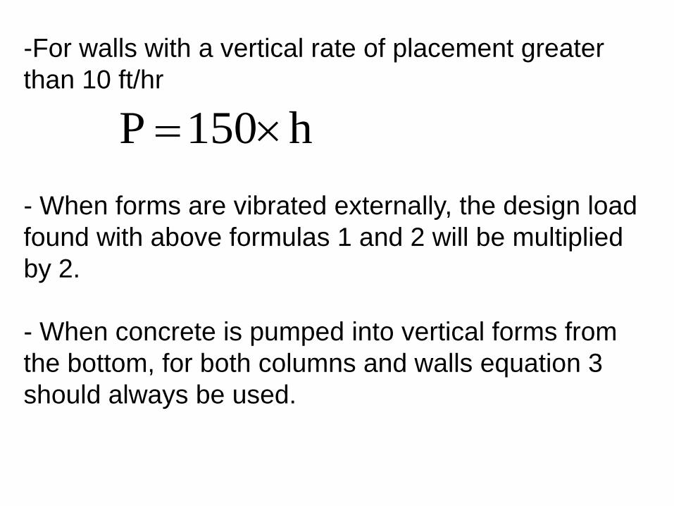
-For walls with a vertical rate of placement greater
than 10 ft/hr
- When forms are vibrated externally, the design load
found with above formulas 1 and 2 will be multiplied
by 2.
- When concrete is pumped into vertical forms from
the bottom, for both columns and walls equation 3
should always be used.
h150P
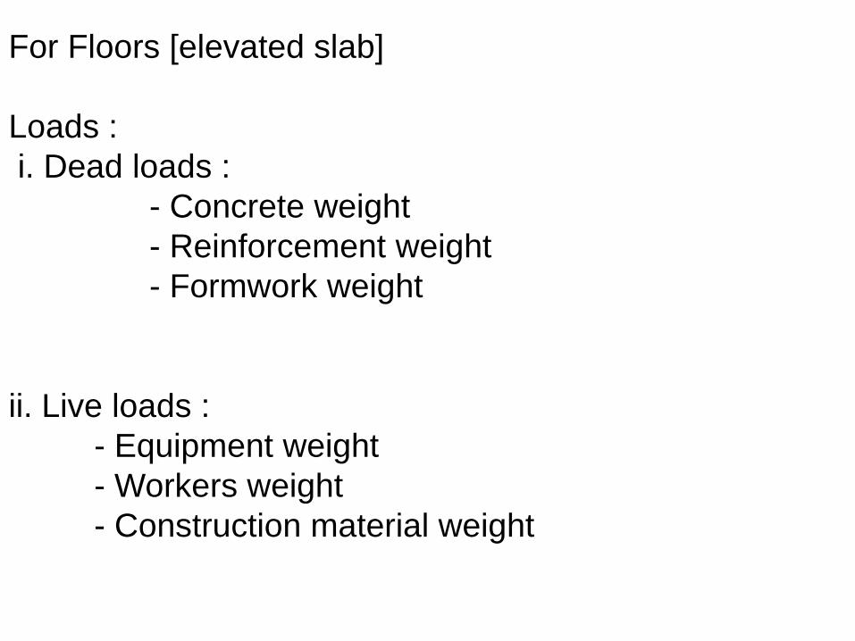
For Floors [elevated slab]
Loads :
i. Dead loads :
- Concrete weight
- Reinforcement weight
- Formwork weight
ii. Live loads :
- Equipment weight
- Workers weight
- Construction material weight
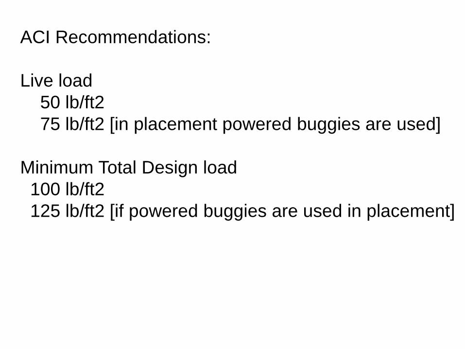
ACI Recommendations:
Live load
50 lb/ft2
75 lb/ft2 [in placement powered buggies are used]
Minimum Total Design load
100 lb/ft2
125 lb/ft2 [if powered buggies are used in placement]
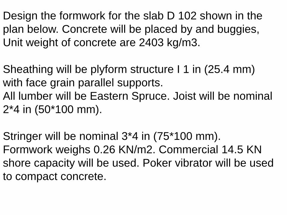
Design the formwork for the slab D 102 shown in the
plan below. Concrete will be placed by and buggies,
Unit weight of concrete are 2403 kg/m3.
Sheathing will be plyform structure I 1 in (25.4 mm)
with face grain parallel supports.
All lumber will be Eastern Spruce. Joist will be nominal
2*4 in (50*100 mm).
Stringer will be nominal 3*4 in (75*100 mm).
Formwork weighs 0.26 KN/m2. Commercial 14.5 KN
shore capacity will be used. Poker vibrator will be used
to compact concrete.
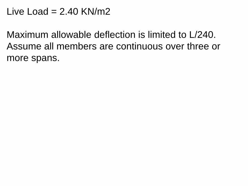
Live Load = 2.40 KN/m2
Maximum allowable deflection is limited to L/240.
Assume all members are continuous over three or
more spans.
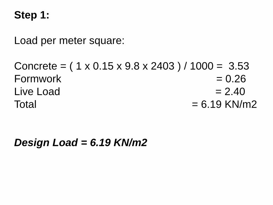
Step 1:
Load per meter square:
Concrete = ( 1 x 0.15 x 9.8 x 2403 ) / 1000 = 3.53
Formwork = 0.26
Live Load = 2.40
Total = 6.19 KN/m2
Design Load = 6.19 KN/m2
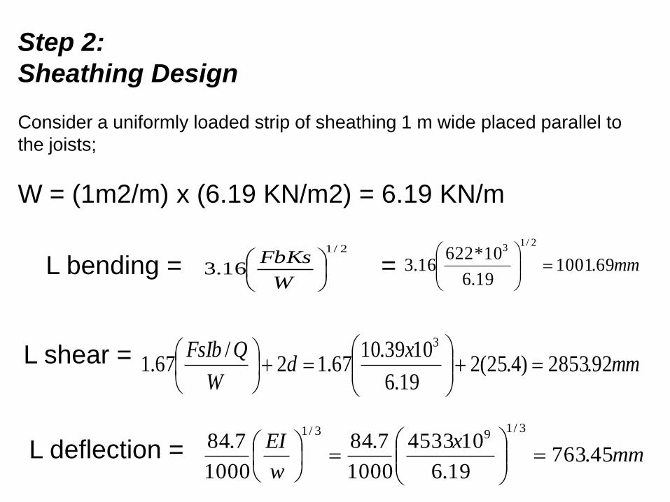
Step 2:
Sheathing Design
Consider a uniformly loaded strip of sheathing 1 m wide placed parallel to
the joists;
W = (1m2/m) x (6.19 KN/m2) = 6.19 KN/m
L bending = = 2/1
16.3
W
FbKs mm69.100119.6
10*62216.3
2/13
L shear = mmx
dW
QFsIb92.2853)4.25(2
19.6
1039.1067.12
/67.1
3
L deflection = mmx
w
EI45.763
19.6
104533
1000
7.84
1000
7.843/1
93/1
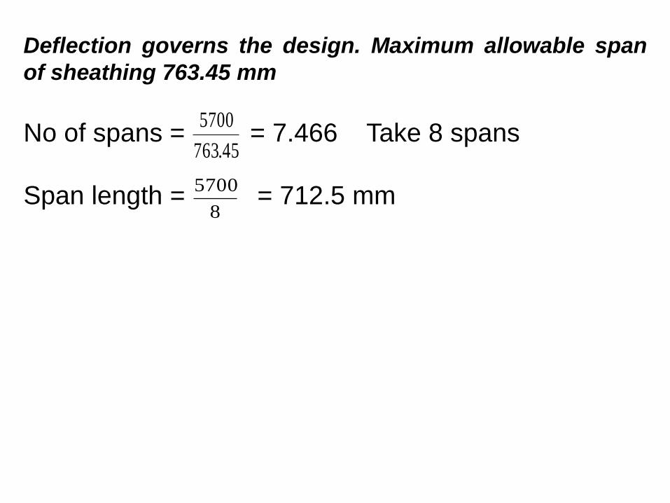
Deflection governs the design. Maximum allowable span
of sheathing 763.45 mm
No of spans = = 7.466 Take 8 spans
Span length = = 712.5 mm
45.763
5700
8
5700
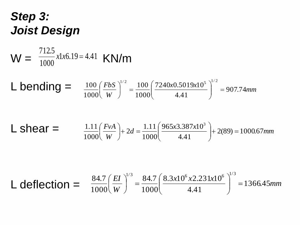
Step 3:
Joist Design
W = KN/m
L bending =
L shear =
L deflection =
41.419.611000
5.712xx
mmxx
W
FbS74.907
41.4
105019.07240
1000
100
1000
1002/1
52/1
mmxx
dW
FvA67.1000)89(2
41.4
10387.3965
1000
11.12
1000
11.1 3
mmxxx
W
EI45.1366
41.4
10231.2103.8
1000
7.84
1000
7.843/1
663/1
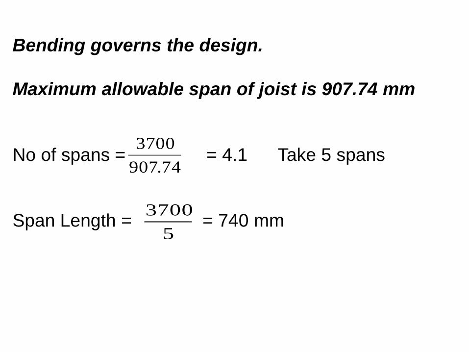
Bending governs the design.
Maximum allowable span of joist is 907.74 mm
No of spans = = 4.1 Take 5 spans
Span Length = = 740 mm
74.907
3700
5
3700
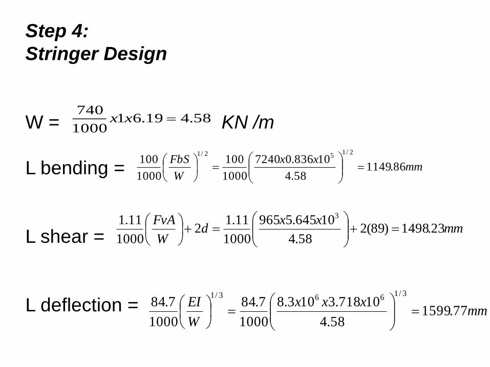
Step 4:
Stringer Design
W = KN /m
L bending =
L shear =
L deflection =
58.419.611000
740xx
mmxx
W
FbS86.1149
58.4
10836.07240
1000
100
1000
1002/1
52/1
mmxx
dW
FvA23.1498)89(2
58.4
10645.5965
1000
11.12
1000
11.1 3
mmxxx
W
EI77.1599
58.4
10718.3103.8
1000
7.84
1000
7.843/1
663/1
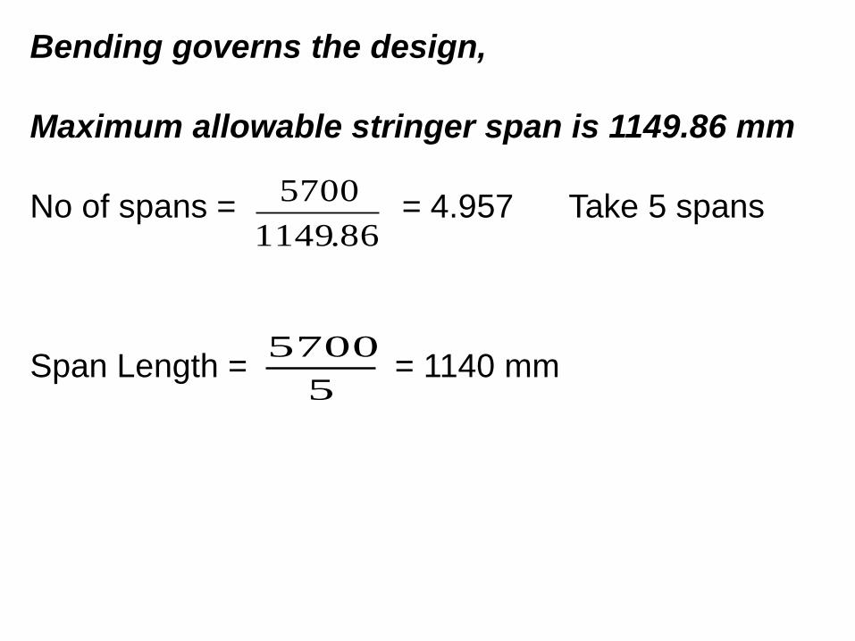
Bending governs the design,
Maximum allowable stringer span is 1149.86 mm
No of spans = = 4.957 Take 5 spans
Span Length = = 1140 mm
86.1149
5700
5
5700
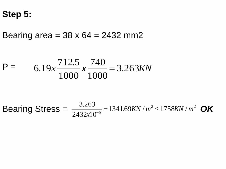
Step 5:
Bearing area = 38 x 64 = 2432 mm2
P =
Bearing Stress = OK
KNxx 263.31000
740
1000
5.71219.6
22
6/1758/69.1341
102432
263.3mKNmKN
x