Embed Size (px)
Citation preview
FORGING SOLUTIONS Design Engineering Information From FIA
IMPRESSION DIE – CASE STUDIES
TABLE OF CONTENTS
Switch From Casting to Forging Increased Life of Large Connecting Rod
Forged Blocker Doors Used to Slow Planes on Landing Provided Cost Savings Compared to Fabricated Part Design Precision Forging Provided Critical Properties and Cost Savings Over Machined Block
Forged Microalloyed Steel Delivered Right Combination of Strength and Toughness for Crankshafts
Forged Chain Stronger, Tougher and Outlasted Castings
Precision Forging Virtually Eliminates Machining, Cuts Cost of Large Structural Aircraft Part
Forged Adapter Cuts Cost by 50%, Resists 2000-psi Pressure Where Casting Could Not
Slack Adjuster Outperformed Casting, Cut Weight, Achieved Optimum ‘Value-Added’ Design on Trucks Forged Microalloyed Steel Crankshaft Replaced ADI in High-Performance Engine
Ready-to-Assemble, Forged Steering Arm Replaced Weldment
Forged Tube Support Replaced Bar Stock, Eliminated All Machining and Cuts Cost by 85%
CVJ ‘tulip’ Finished As-forged, Cut Cost and Eliminated Expensive Machining Operations
Capability Analysis Brought Process into Control, Boosted Quality of Forged Automotive Parts
Co-Operative Redesign Delivered Forged Stop Nut, Eliminated Machining, and Consolidated Parts Redesign Plus Teamwork Produced a Forged Part, Saving 80% in Material Cost Over Casting
Forged-microalloyed Yoke for Driveline Delivered Net Savings Plus Increased Performance
Forged Aluminum Ejector Cut Cost, Provided Critical Dimensions
Forging Techniques Made Steel Cam Cost-effective for High-volume Production
Forged Microalloyed Steel Engine Mount Cut Cost, Outperformed Alternatives
Forged Track Links Perform, Thanks to Harden-and-Temper + Induction
Forging Replaced Casting in Friction-welded Assembly, Cut Cost by Streamlining Manufacturing Operations
CASE STUDY FROM THE FILES:Switch from casting to forging increased life of large connecting rod
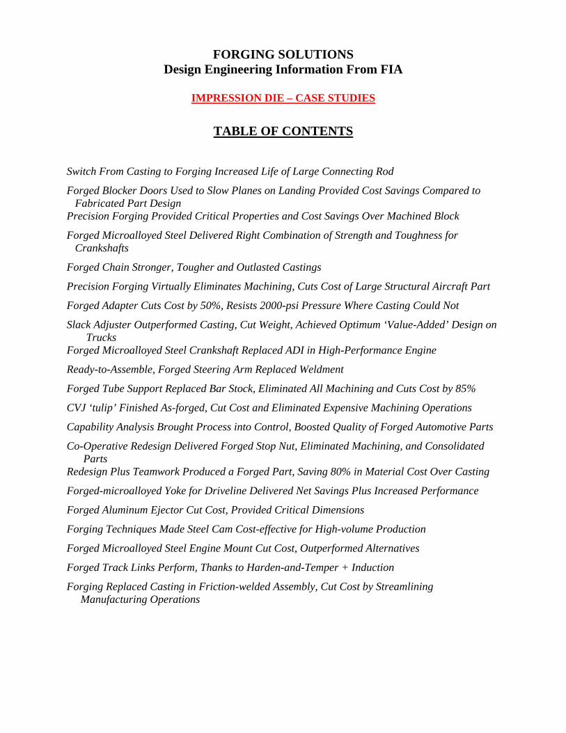
Field failures, an expensiveproposition in terms of down-time and major pump damage,showed that cast connectingrods used to drive the pumpsthat keep coal slurry movingthrough pipelines were notstrong enough.
The solution to the problemwas found by redesigning thecast connecting rod as a forg-ing. By refining grain flow inthe closed-die hammer forgingprocess, additional strength wasdistributed to the points ofhighest stress. Forging not onlyboosted the magnitude of thetensile strength over the castversion, but also significantlyimproved the strength of theconnecting rods in the trans-verse direction.With the alternating stresses that the rod experiences while in service, longer life as a result ofimproved fatigue strength also became a reality.
The forged 4140 steel connecting rod achieved critical straightness and thickness tolerances. See figure above.Tolerances are an important consideration, since as-forged surfaces must meet critical dimensional requirements toensure a trouble-free installation.The tight tolerances permitted a large portion of the plan view area to be used asforged without subsequent finish machining.
As larger, more powerful pumps are designed and built to move greater volumes of slurry through larger pipelinesover longer distances, the improved performance of forged connecting rods can increase the reliability of the pumps.
Refined grain flow in a 2450 lb. steel connecting rod delivers improved transversestrength, permitted a forging to succeed where a casting failed.
Design Engineering Information From FIA
FORGINGSOLUTIONS
Addressing these processes:
Impression Die
Open Die
Rolled Ring
Cold
FORGING INDUSTRY ASSOCIATION25 West Prospect Ave., Suite 300, Cleveland, OH 44115Phone: 216-781-6260 Fax: 216-781-0102 E-mail: [email protected] Website: www.forging.org
© Copyright 2007, Forging Industry Association
CASE STUDY FROM THE FILES:Forged blocker doors used to slow planes on landing provided cost savings compared to fabricated part design
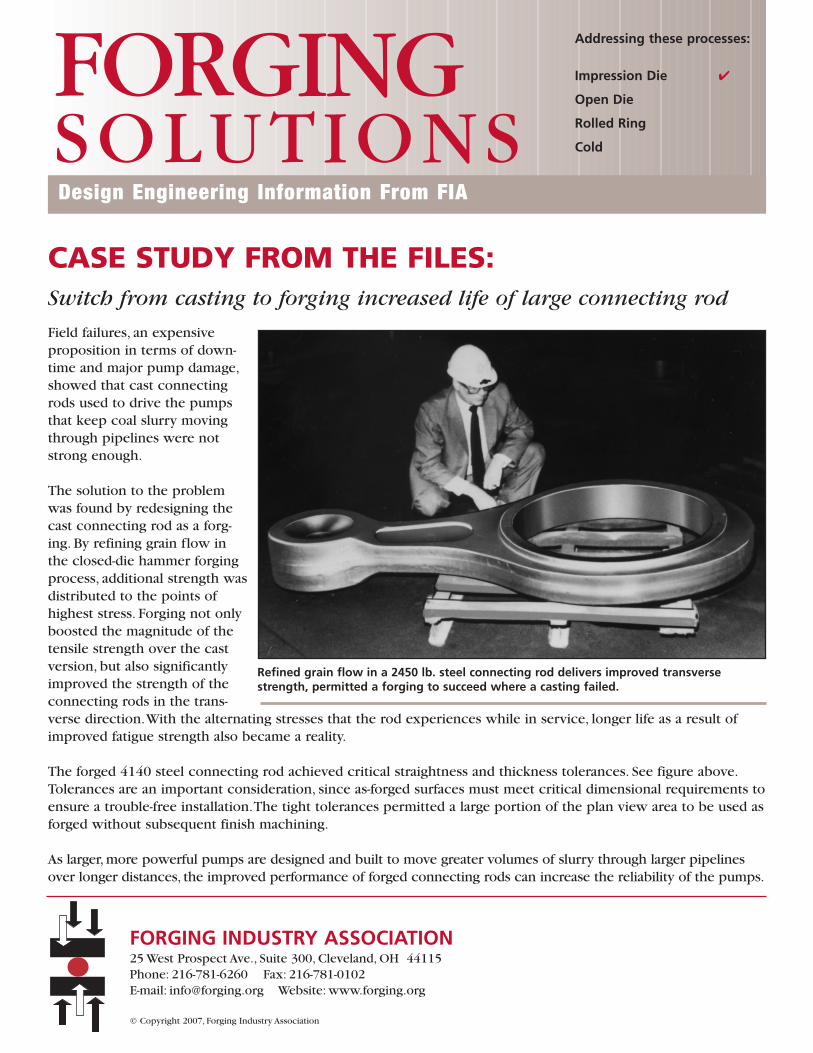
Previously made as a complex fabricat-ed build-up, precision forged aluminumblocker doors for jet engines deliveredwhat is estimated as severalfold costsavings.
Actuated by the thrust reversers in a jetengine to reverse the jet stream andslow down a plane upon landing, theblocker doors were previously a built-up structure, consisting of aluminumsheet and honeycomb, which are bothadhesively bonded and mechanicallyfastened.
As a one-piece forging, the re-designedblocker door incorporated integral stiff-ening ribs and a hinge attachment, bothof which were formed to net shape.Theonly subsequent operation -- a single symmetrical machining set-up -- was performed on the conical-shaped backcontour side. By establishing a single database to program tool paths for the EDM electrodes used to produce theforging dies, as well as for the machine/straightening fixture, the forger was able to achieve improved tolerances.
In addition to achieving savings in manufacturing and assembly, the forged doors were significantly more dam-age-tolerant than the sheet/honeycomb sandwich construction.As a result, longer service life provided furthercost savings.
Design Engineering Information From FIA
FORGINGSOLUTIONS
Addressing these processes:
Impression Die
Open Die
Rolled Ring
Cold
Precision forged of 2014-T6 aluminum to reduce cost, a blocker door for jetengines also outperformed its labor intensive fabricated predecessor. Shownare the detailed rib side and hinge attachment area, which was forged "net".
FORGING INDUSTRY ASSOCIATION25 West Prospect Ave., Suite 300, Cleveland, OH 44115Phone: 216-781-6260 Fax: 216-781-0102 E-mail: [email protected] Website: www.forging.org
© Copyright 2007, Forging Industry Association
CASE STUDY FROM THE FILES:Precision forging provided critical properties and cost savings overmachined block
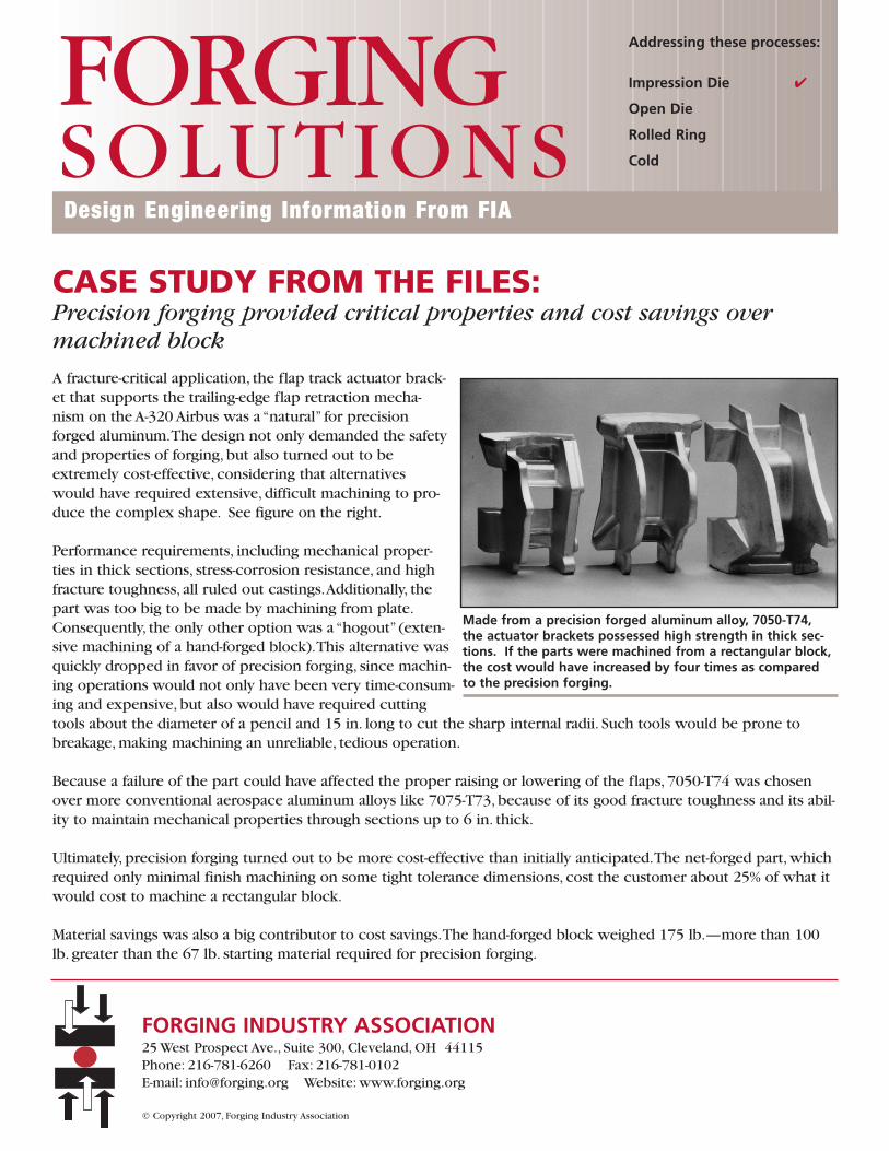
A fracture-critical application, the flap track actuator brack-et that supports the trailing-edge flap retraction mecha-nism on the A-320 Airbus was a “natural” for precisionforged aluminum.The design not only demanded the safetyand properties of forging, but also turned out to beextremely cost-effective, considering that alternativeswould have required extensive, difficult machining to pro-duce the complex shape. See figure on the right.
Performance requirements, including mechanical proper-ties in thick sections, stress-corrosion resistance, and highfracture toughness, all ruled out castings.Additionally, thepart was too big to be made by machining from plate.Consequently, the only other option was a “hogout” (exten-sive machining of a hand-forged block).This alternative wasquickly dropped in favor of precision forging, since machin-ing operations would not only have been very time-consum-ing and expensive, but also would have required cuttingtools about the diameter of a pencil and 15 in. long to cut the sharp internal radii. Such tools would be prone tobreakage, making machining an unreliable, tedious operation.
Because a failure of the part could have affected the proper raising or lowering of the flaps, 7050-T74 was chosenover more conventional aerospace aluminum alloys like 7075-T73, because of its good fracture toughness and its abil-ity to maintain mechanical properties through sections up to 6 in. thick.
Ultimately, precision forging turned out to be more cost-effective than initially anticipated.The net-forged part, whichrequired only minimal finish machining on some tight tolerance dimensions, cost the customer about 25% of what itwould cost to machine a rectangular block.
Material savings was also a big contributor to cost savings.The hand-forged block weighed 175 lb.—more than 100lb. greater than the 67 lb. starting material required for precision forging.
Made from a precision forged aluminum alloy, 7050-T74,the actuator brackets possessed high strength in thick sec-tions. If the parts were machined from a rectangular block,the cost would have increased by four times as comparedto the precision forging.
Design Engineering Information From FIA
FORGINGSOLUTIONS
Addressing these processes:
Impression Die
Open Die
Rolled Ring
Cold
FORGING INDUSTRY ASSOCIATION25 West Prospect Ave., Suite 300, Cleveland, OH 44115Phone: 216-781-6260 Fax: 216-781-0102 E-mail: [email protected] Website: www.forging.org
© Copyright 2007, Forging Industry Association
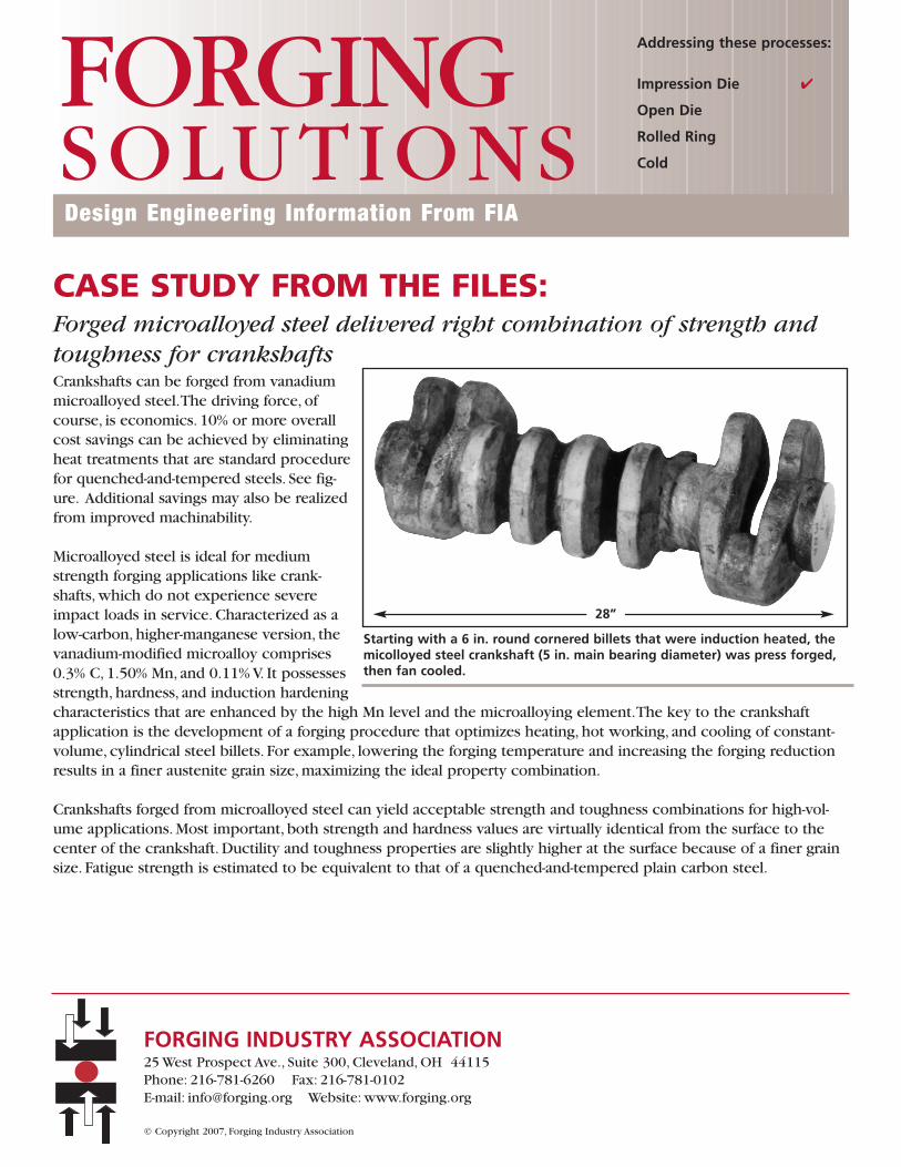
CASE STUDY FROM THE FILES:Forged microalloyed steel delivered right combination of strength andtoughness for crankshaftsCrankshafts can be forged from vanadiummicroalloyed steel.The driving force, ofcourse, is economics. 10% or more overallcost savings can be achieved by eliminatingheat treatments that are standard procedurefor quenched-and-tempered steels. See fig-ure. Additional savings may also be realizedfrom improved machinability.
Microalloyed steel is ideal for mediumstrength forging applications like crank-shafts, which do not experience severeimpact loads in service. Characterized as alow-carbon, higher-manganese version, thevanadium-modified microalloy comprises0.3% C, 1.50% Mn, and 0.11% V. It possessesstrength, hardness, and induction hardeningcharacteristics that are enhanced by the high Mn level and the microalloying element.The key to the crankshaftapplication is the development of a forging procedure that optimizes heating, hot working, and cooling of constant-volume, cylindrical steel billets. For example, lowering the forging temperature and increasing the forging reductionresults in a finer austenite grain size, maximizing the ideal property combination.
Crankshafts forged from microalloyed steel can yield acceptable strength and toughness combinations for high-vol-ume applications. Most important, both strength and hardness values are virtually identical from the surface to thecenter of the crankshaft. Ductility and toughness properties are slightly higher at the surface because of a finer grainsize. Fatigue strength is estimated to be equivalent to that of a quenched-and-tempered plain carbon steel.
Starting with a 6 in. round cornered billets that were induction heated, themicolloyed steel crankshaft (5 in. main bearing diameter) was press forged,then fan cooled.
Design Engineering Information From FIA
FORGINGSOLUTIONS
Addressing these processes:
Impression Die
Open Die
Rolled Ring
Cold
FORGING INDUSTRY ASSOCIATION25 West Prospect Ave., Suite 300, Cleveland, OH 44115Phone: 216-781-6260 Fax: 216-781-0102 E-mail: [email protected] Website: www.forging.org
© Copyright 2007, Forging Industry Association
28”
CASE STUDY FROM THE FILES:Forged chain stronger, tougher and outlasted castingsUsed primarily in coal mining but also in other typesof surface mining, giant dragline chains hoist bucketsfilled with coal, phosphate, or ore up from the miningsite.As the old saying goes,“Any chain is only asstrong as its weakest link.”
One company found that cast dragline chains werenot strong enough.The cast links were continually
failing. Engineersswitched to forgedchain links, significant-ly increasing servicelife over that of castchains.
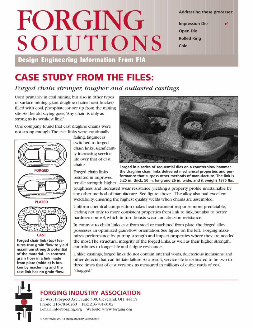
Forged chain linksresulted in improvedtensile strength, highertoughness, and increased wear resistance, yielding a property profile unattainable byany other method of manufacture. See figure above. The alloy also had excellent weldability, ensuring the highest quality welds when chains are assembled.
Uniform chemical composition makes heat-treatment response more predictable,leading not only to more consistent properties from link to link, but also to better hardness control, which in turn boosts wear and abrasion resistance.
In contrast to chain links cast from steel or machined from plate, the forged alloy possesses an optimized grain-flow orientation. See figure on the left. Forging maxi-mizes performance by putting strength and impact properties where they are neededthe most.The structural integrity of the forged links, as well as their higher strength,contributes to longer life and fatigue resistance.
Unlike castings, forged links do not contain internal voids, deleterious inclusions, andother defects that can initiate failure.As a result, service life is estimated to be two tothree times that of cast versions, as measured in millions of cubic yards of coal“dragged.”
Forged in a series of sequential dies on a counterblow hammer,the dragline chain links delivered mechanical properties and per-formance that surpass other methods of manufacture. The link is5.25 in. thick, 50 in. long and 26 in. wide, and it weighs 1375 lbs.
Design Engineering Information From FIA
FORGINGSOLUTIONS
Addressing these processes:
Impression Die
Open Die
Rolled Ring
Cold
Forged chair link (top) fea-tures true grain flow to yieldmaximum strength potentialof the material. In contrastgrain flow in a link madefrom plate (middle) is bro-ken by machining and thecast link has no grain flow.
FORGED
PLATED
CAST
FORGING INDUSTRY ASSOCIATION25 West Prospect Ave., Suite 300, Cleveland, OH 44115Phone: 216-781-6260 Fax: 216-781-0102 E-mail: [email protected] Website: www.forging.org
© Copyright 2007, Forging Industry Association
CASE STUDY FROM THE FILES:Precision forging virtually eliminates machining, cuts cost of largestructural aircraft part
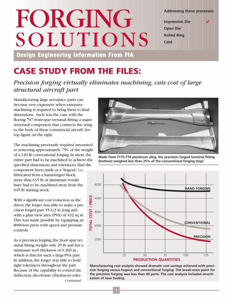
Manufacturing large aerospace parts canbecome very expensive when extensivemachining is required to bring them to finaldimensions. Such was the case with theBoeing 767 front-spar terminal fitting, a majorstructural component that connects the wingto the body of these commercial aircraft. Seetop figure on the right.
The machining previously required amountedto removing approximately 75% of the weightof a 120 lb conventional forging. In short, theentire part had to be machined to achieve thespecified dimensions and tolerances. Had thecomponent been made as a “hogout,” i.e.,fabricated from a hand-forged block,more than 615 lb of aluminum wouldhave had to be machined away from the645 lb starting stock.
With a significant cost reduction as thedriver, the forger was able to make a pre-cision forged part 55-1/2 in. long andwith a plan view area (PVA) of 432 sq in.This was made possible by equipping an8000-ton press with speed and pressurecontrols.
As a precision forging, the front spar ter-minal fitting weighs only 29 lb and has aminimum web thickness of 0.260 in.,which is thin for such a large-PVA part.In addition, the forger was able to holdtight tolerances throughout the part.Because of the capability to control diedeflection, die-closure (thickness) toler-
Made from 7175-T74 aluminum alloy, the precision forged terminal fitting(bottom) weighed less than 25% of the conventional forging (top)
Design Engineering Information From FIA
FORGINGSOLUTIONS
Addressing these processes:
Impression Die
Open Die
Rolled Ring
Cold
Continued
1
Manufacturing cost analysis showed dramatic cost savings achieved with preci-sion forging versus hogout and conventional forging. The break-even point forthe precision forging was less than 40 parts. The cost analysis included amorti-zation of new tooling.
PRODUCTION QUANTITIES25 50 75 100 125
TOTA
L C
OST
/ P
RIC
E
6000
5000
4000
3000
2000
HAND FORGING
CONVENTIONAL
PRECISION
CONTINUEDFORGING SOLUTIONS
FORGING INDUSTRY ASSOCIATION25 West Prospect Ave., Suite 300, Cleveland, OH 44115Phone: 216-781-6260 Fax: 216-781-0102 E-mail: [email protected] Website: www.forging.org
© Copyright 2007, Forging Industry Association
ances were held to +0.030/-0.010 in., which are tighter than normal for a part of that size. Similarly, length dimen-sions are held to ± 0.010 in. by performing a simple machining operation on both ends.
Even if certain dimensions and tolerances on a precision component are not practical to forge, or are perhaps tooexpensive to hold in the forging process, economical options such as machining and chemical-milling can be usedon specific part features.
The forger performs the only machining required, which facilitates attachment of mating parts. This value-addedservice eliminates any machining by the airframe manufacturer, other than merely drilling assembly holes.
Overall, significant cost savings are attributed to precision forging. See bottom figure on page 1. Savings in machin-ing dollars were eight times greater than the increase in cost resulting from the switch from conventional to preci-sion forging. Further, with practically no machining required, production time is considerably reduced.
CASE STUDY FROM THE FILES:Forged adapter cuts cost by 50%, resists 2000-psi pressure where castingcould not
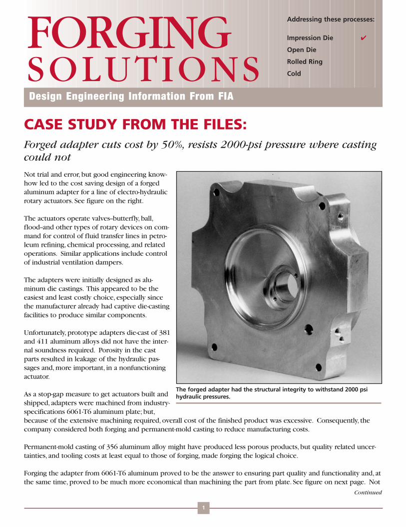
Not trial and error, but good engineering know-how led to the cost saving design of a forgedaluminum adapter for a line of electro-hydraulicrotary actuators. See figure on the right.
The actuators operate valves--butterfly, ball,flood--and other types of rotary devices on com-mand for control of fluid transfer lines in petro-leum refining, chemical processing, and relatedoperations. Similar applications include controlof industrial ventilation dampers.
The adapters were initially designed as alu-minum die castings. This appeared to be theeasiest and least costly choice, especially sincethe manufacturer already had captive die-castingfacilities to produce similar components.
Unfortunately, prototype adapters die-cast of 381and 411 aluminum alloys did not have the inter-nal soundness required. Porosity in the castparts resulted in leakage of the hydraulic pas-sages and, more important, in a nonfunctioningactuator.
As a stop-gap measure to get actuators built andshipped, adapters were machined from industry-specifications 6061-T6 aluminum plate; but,because of the extensive machining required, overall cost of the finished product was excessive. Consequently, thecompany considered both forging and permanent-mold casting to reduce manufacturing costs.
Permanent-mold casting of 356 aluminum alloy might have produced less porous products, but quality related uncer-tainties, and tooling costs at least equal to those of forging, made forging the logical choice.
Forging the adapter from 6061-T6 aluminum proved to be the answer to ensuring part quality and functionality and, atthe same time, proved to be much more economical than machining the part from plate. See figure on next page. Not
The forged adapter had the structural integrity to withstand 2000 psihydraulic pressures.
Design Engineering Information From FIA
FORGINGSOLUTIONS
Addressing these processes:
Impression Die
Open Die
Rolled Ring
Cold
Continued
1
CONTINUEDFORGING SOLUTIONS
FORGING INDUSTRY ASSOCIATION25 West Prospect Ave., Suite 300, Cleveland, OH 44115Phone: 216-781-6260 Fax: 216-781-0102 E-mail: [email protected] Website: www.forging.org
© Copyright 2007, Forging Industry Association
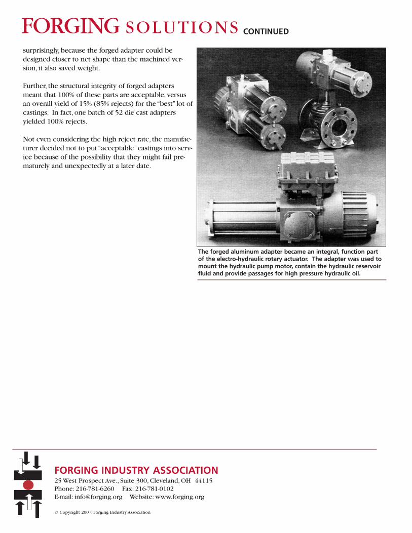
surprisingly, because the forged adapter could bedesigned closer to net shape than the machined ver-sion, it also saved weight.
Further, the structural integrity of forged adaptersmeant that 100% of these parts are acceptable, versusan overall yield of 15% (85% rejects) for the “best” lot ofcastings. In fact, one batch of 52 die cast adaptersyielded 100% rejects.
Not even considering the high reject rate, the manufac-turer decided not to put “acceptable”castings into serv-ice because of the possibility that they might fail pre-maturely and unexpectedly at a later date.
The forged aluminum adapter became an integral, function partof the electro-hydraulic rotary actuator. The adapter was used tomount the hydraulic pump motor, contain the hydraulic reservoirfluid and provide passages for high pressure hydraulic oil.
CASE STUDY FROM THE FILES:Slack adjuster outperformed casting, cut weight, achieved optimum'value-added' design on trucks
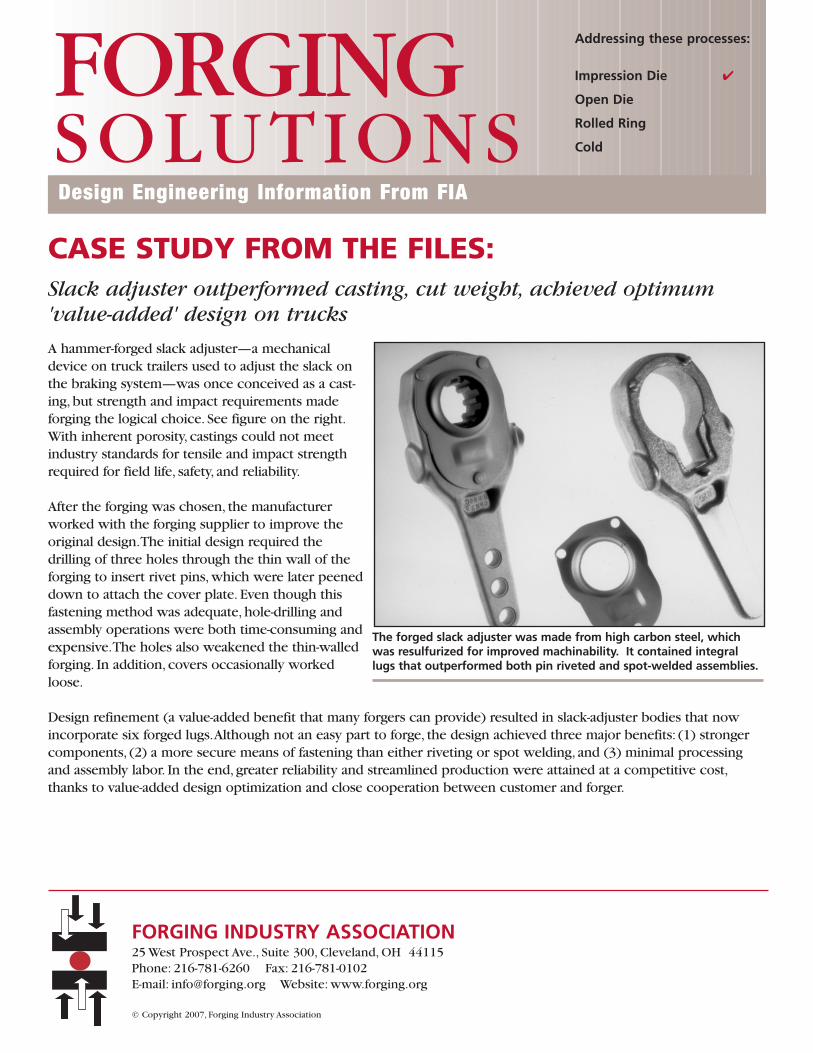
A hammer-forged slack adjuster—a mechanicaldevice on truck trailers used to adjust the slack onthe braking system—was once conceived as a cast-ing, but strength and impact requirements madeforging the logical choice. See figure on the right.With inherent porosity, castings could not meetindustry standards for tensile and impact strengthrequired for field life, safety, and reliability.
After the forging was chosen, the manufacturerworked with the forging supplier to improve theoriginal design.The initial design required thedrilling of three holes through the thin wall of theforging to insert rivet pins, which were later peeneddown to attach the cover plate. Even though thisfastening method was adequate, hole-drilling andassembly operations were both time-consuming andexpensive.The holes also weakened the thin-walledforging. In addition, covers occasionally workedloose.
Design refinement (a value-added benefit that many forgers can provide) resulted in slack-adjuster bodies that nowincorporate six forged lugs.Although not an easy part to forge, the design achieved three major benefits: (1) strongercomponents, (2) a more secure means of fastening than either riveting or spot welding, and (3) minimal processingand assembly labor. In the end, greater reliability and streamlined production were attained at a competitive cost,thanks to value-added design optimization and close cooperation between customer and forger.
The forged slack adjuster was made from high carbon steel, whichwas resulfurized for improved machinability. It contained integrallugs that outperformed both pin riveted and spot-welded assemblies.
Design Engineering Information From FIA
FORGINGSOLUTIONS
Addressing these processes:
Impression Die
Open Die
Rolled Ring
Cold
FORGING INDUSTRY ASSOCIATION25 West Prospect Ave., Suite 300, Cleveland, OH 44115Phone: 216-781-6260 Fax: 216-781-0102 E-mail: [email protected] Website: www.forging.org
© Copyright 2007, Forging Industry Association

CASE STUDY FROM THE FILES:Forged microalloyed steel crankshaft replaced ADI in high-performanceengine
A forged vanadium microalloyed steelcrankshaft for a high-performance supercharged engine delivered properties thatfar surpassed those of a conventional nodu-lar-iron crankshaft. See figure on the right.
Although the original design specifiedADI (austempered ductile iron), the mate-rial was incapable of achieving engineer-ing targets for property consistency andmachinability.This traces back to thecomplexities of melting and casting thismaterial to achieve consistent responsein heat treatment.
The best solution to this problem was the selection of a forging, whose strength, modulus, and fatigue properties fulfillhigher-performance criteria required. Because a microalloyed steel was selected, properties were achieved “as-forged,”eliminating the expense of quenching and tempering operations that forged carbon-steel cranks routinely require.
Final properties of the microalloyed-steel forgings far surpass those of typical nodular iron. For the forged crank, mini-mum yield strength is 72,000 versus 55,000 psi for nodular iron; minimum tensile strength, 120,000 versus 85,000 psi.In addition, steel's modulus of elasticity is 30 million psi, compared to a minimum 22 million psi for nodular iron.Thishigher stiffness further enhances performance under higher in-service stresses. Equally important, fatigue strength ofthe forged crank (without additional operations to improve fatigue properties in selected areas) is estimated at 55,000psi, far surpassing that of nodular iron at 32,000 to 35,000 psi.
To further boost fatigue life, engineers opted to use shot-peening and not the usual deep-rolling process to increasefatigue properties on main journals only.The shot-peening performed on all journals (both main and pin) increasedfatigue strength by an estimated 30%. Basically, shot-peening of the steel crank's fillets induces compressive stresses (onthe surface), which must be overcome before tensile stresses can affect those part areas. Consequently, designersexpect longer lives, or no failures whatsoever.
The forged microalloyed steel crankshaft for a supercharged engine outper-formed conventional ductile iron cranks.
Design Engineering Information From FIA
FORGINGSOLUTIONS
Addressing these processes:
Impression Die
Open Die
Rolled Ring
Cold
FORGING INDUSTRY ASSOCIATION25 West Prospect Ave., Suite 300, Cleveland, OH 44115Phone: 216-781-6260 Fax: 216-781-0102 E-mail: [email protected] Website: www.forging.org
© Copyright 2007, Forging Industry Association
CASE STUDY FROM THE FILES:Ready-to-assemble, forged steering arm replaced weldment
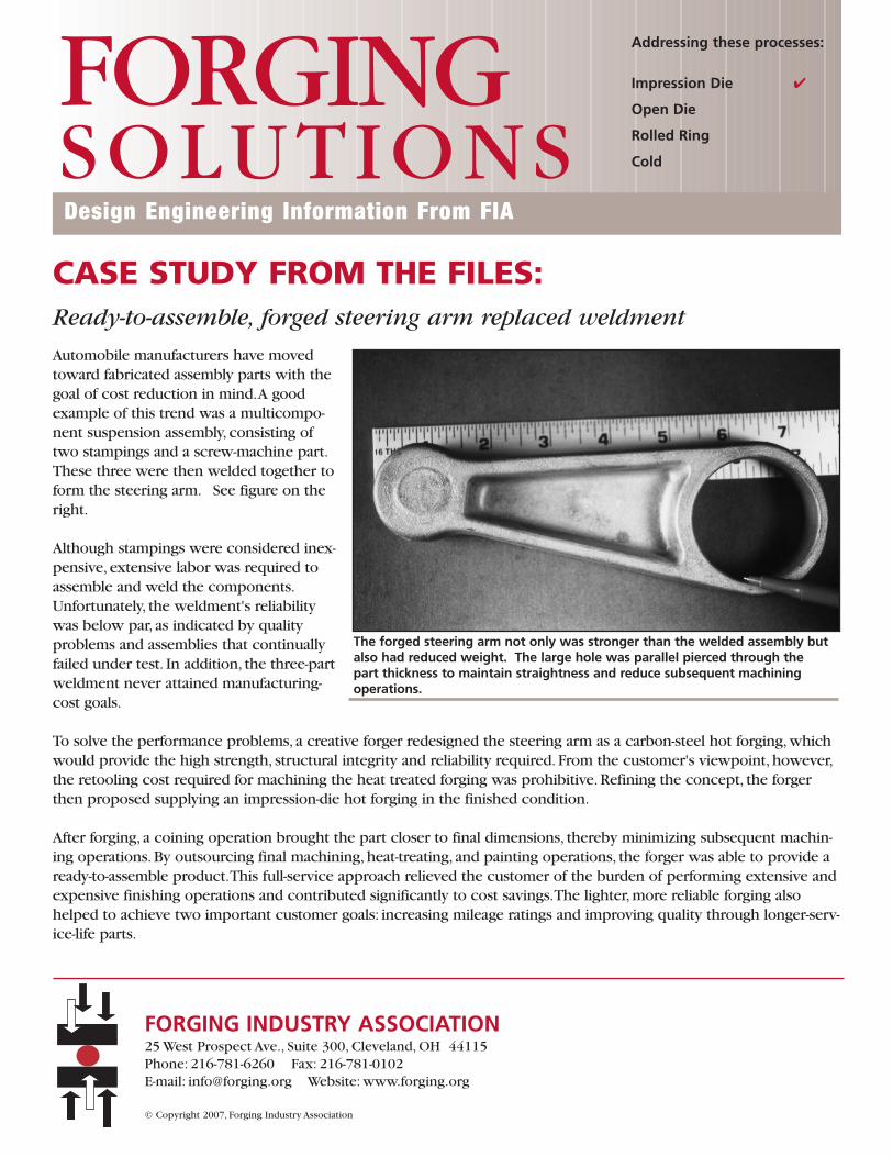
Automobile manufacturers have movedtoward fabricated assembly parts with thegoal of cost reduction in mind.A goodexample of this trend was a multicompo-nent suspension assembly, consisting oftwo stampings and a screw-machine part.These three were then welded together toform the steering arm. See figure on theright.
Although stampings were considered inex-pensive, extensive labor was required toassemble and weld the components.Unfortunately, the weldment's reliabilitywas below par, as indicated by qualityproblems and assemblies that continuallyfailed under test. In addition, the three-partweldment never attained manufacturing-cost goals.
To solve the performance problems, a creative forger redesigned the steering arm as a carbon-steel hot forging, whichwould provide the high strength, structural integrity and reliability required. From the customer's viewpoint, however,the retooling cost required for machining the heat treated forging was prohibitive. Refining the concept, the forgerthen proposed supplying an impression-die hot forging in the finished condition.
After forging, a coining operation brought the part closer to final dimensions, thereby minimizing subsequent machin-ing operations. By outsourcing final machining, heat-treating, and painting operations, the forger was able to provide aready-to-assemble product.This full-service approach relieved the customer of the burden of performing extensive andexpensive finishing operations and contributed significantly to cost savings.The lighter, more reliable forging alsohelped to achieve two important customer goals: increasing mileage ratings and improving quality through longer-serv-ice-life parts.
The forged steering arm not only was stronger than the welded assembly butalso had reduced weight. The large hole was parallel pierced through the part thickness to maintain straightness and reduce subsequent machining operations.
Design Engineering Information From FIA
FORGINGSOLUTIONS
Addressing these processes:
Impression Die
Open Die
Rolled Ring
Cold
FORGING INDUSTRY ASSOCIATION25 West Prospect Ave., Suite 300, Cleveland, OH 44115Phone: 216-781-6260 Fax: 216-781-0102 E-mail: [email protected] Website: www.forging.org
© Copyright 2007, Forging Industry Association
CASE STUDY FROM THE FILES:Forged tube support replaced bar stock, eliminated all machining andcuts cost by 85%
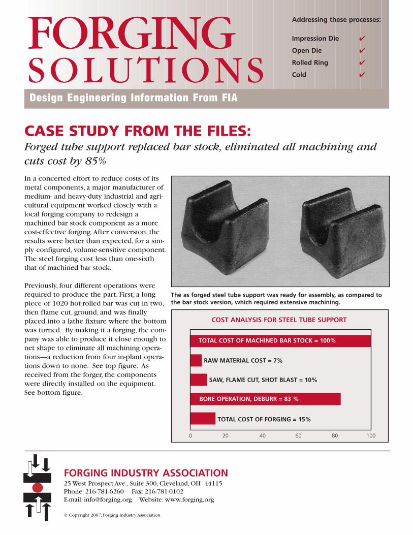
In a concerted effort to reduce costs of itsmetal components, a major manufacturer ofmedium- and heavy-duty industrial and agri-cultural equipment worked closely with alocal forging company to redesign amachined bar stock component as a morecost-effective forging.After conversion, theresults were better than expected, for a sim-ply configured, volume-sensitive component.The steel forging cost less than one-sixththat of machined bar stock.
Previously, four different operations wererequired to produce the part. First, a longpiece of 1020 hot-rolled bar was cut in two,then flame cut, ground, and was finallyplaced into a lathe fixture where the bottomwas turned. By making it a forging, the com-pany was able to produce it close enough tonet shape to eliminate all machining opera-tions—a reduction from four in-plant opera-tions down to none. See top figure. Asreceived from the forger, the componentswere directly installed on the equipment.See bottom figure.
Design Engineering Information From FIA
FORGINGSOLUTIONS
Addressing these processes:
Impression Die
Open Die
Rolled Ring
Cold
FORGING INDUSTRY ASSOCIATION25 West Prospect Ave., Suite 300, Cleveland, OH 44115Phone: 216-781-6260 Fax: 216-781-0102 E-mail: [email protected] Website: www.forging.org
© Copyright 2007, Forging Industry Association
The as forged steel tube support was ready for assembly, as compared tothe bar stock version, which required extensive machining.
COST ANALYSIS FOR STEEL TUBE SUPPORT
0 20 40 60 80 100
TOTAL COST OF MACHINED BAR STOCK = 100%
RAW MATERIAL COST = 7%
SAW, FLAME CUT, SHOT BLAST = 10%
BORE OPERATION, DEBURR = 83 %
TOTAL COST OF FORGING = 15%
CASE STUDY FROM THE FILES:CVJ 'tulip' finished as-forged, cut cost and eliminated expensive machining operations
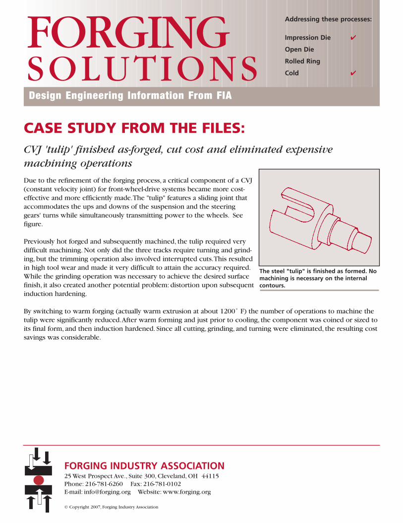
Due to the refinement of the forging process, a critical component of a CVJ(constant velocity joint) for front-wheel-drive systems became more cost-effective and more efficiently made.The "tulip" features a sliding joint thataccommodates the ups and downs of the suspension and the steeringgears' turns while simultaneously transmitting power to the wheels. Seefigure.
Previously hot forged and subsequently machined, the tulip required verydifficult machining. Not only did the three tracks require turning and grind-ing, but the trimming operation also involved interrupted cuts.This resultedin high tool wear and made it very difficult to attain the accuracy required.While the grinding operation was necessary to achieve the desired surfacefinish, it also created another potential problem: distortion upon subsequentinduction hardening.
By switching to warm forging (actually warm extrusion at about 1200˚ F) the number of operations to machine thetulip were significantly reduced.After warm forming and just prior to cooling, the component was coined or sized toits final form, and then induction hardened. Since all cutting, grinding, and turning were eliminated, the resulting costsavings was considerable.
The steel "tulip" is finished as formed. Nomachining is necessary on the internalcontours.
Design Engineering Information From FIA
FORGINGSOLUTIONS
Addressing these processes:
Impression Die
Open Die
Rolled Ring
Cold
FORGING INDUSTRY ASSOCIATION25 West Prospect Ave., Suite 300, Cleveland, OH 44115Phone: 216-781-6260 Fax: 216-781-0102 E-mail: [email protected] Website: www.forging.org
© Copyright 2007, Forging Industry Association
CASE STUDY FROM THE FILES:Capability analysis brought process into control, boosted quality offorged automotive parts
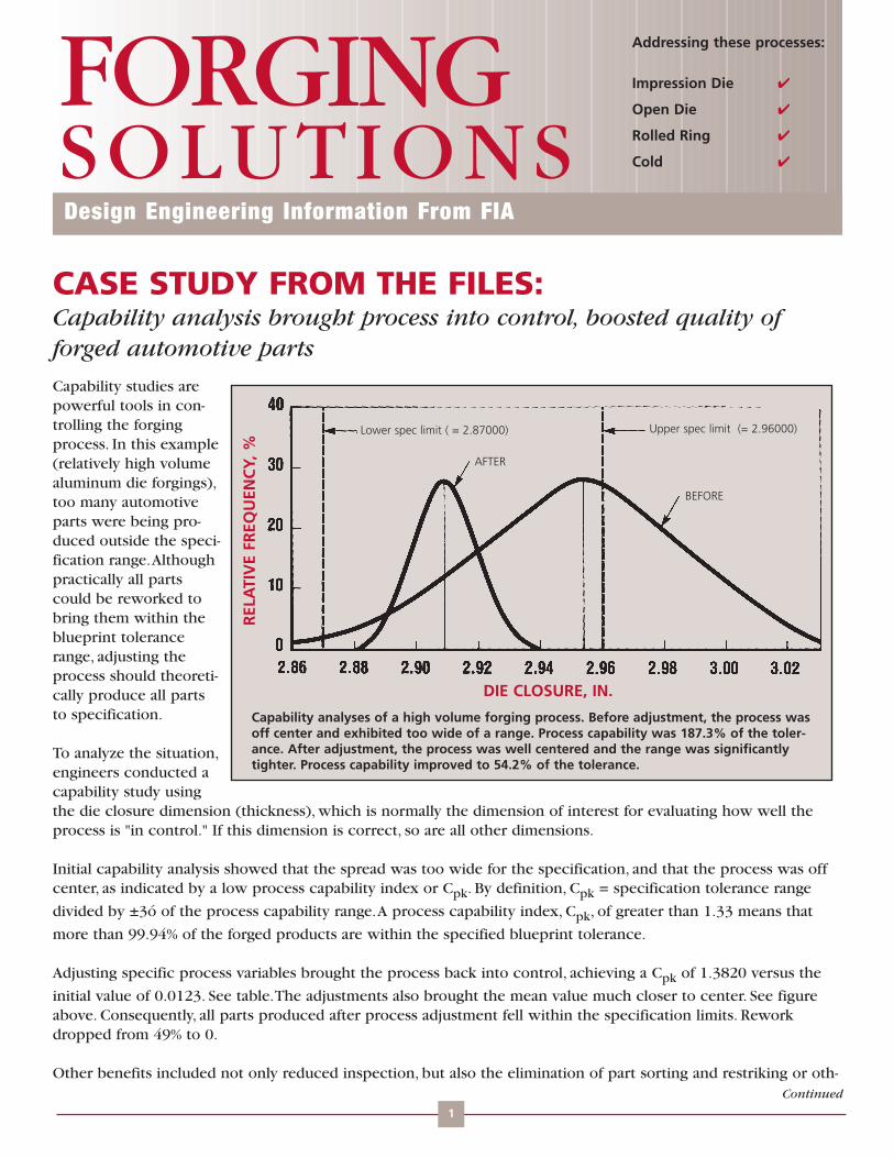
Capability studies arepowerful tools in con-trolling the forgingprocess. In this example(relatively high volumealuminum die forgings),too many automotiveparts were being pro-duced outside the speci-fication range.Althoughpractically all partscould be reworked tobring them within theblueprint tolerancerange, adjusting theprocess should theoreti-cally produce all partsto specification.
To analyze the situation,engineers conducted acapability study usingthe die closure dimension (thickness), which is normally the dimension of interest for evaluating how well theprocess is "in control." If this dimension is correct, so are all other dimensions.
Initial capability analysis showed that the spread was too wide for the specification, and that the process was offcenter, as indicated by a low process capability index or Cpk. By definition, Cpk = specification tolerance range
divided by ±3ó of the process capability range.A process capability index, Cpk, of greater than 1.33 means that
more than 99.94% of the forged products are within the specified blueprint tolerance.
Adjusting specific process variables brought the process back into control, achieving a Cpk of 1.3820 versus the
initial value of 0.0123. See table.The adjustments also brought the mean value much closer to center. See figureabove. Consequently, all parts produced after process adjustment fell within the specification limits. Reworkdropped from 49% to 0.
Other benefits included not only reduced inspection, but also the elimination of part sorting and restriking or oth-
Design Engineering Information From FIA
FORGINGSOLUTIONS
Addressing these processes:
Impression Die
Open Die
Rolled Ring
Cold
DIE CLOSURE, IN.
REL
ATI
VE
FREQ
UEN
CY,
%
Upper spec limit (= 2.96000)Lower spec limit ( = 2.87000)
AFTER
BEFORE
Capability analyses of a high volume forging process. Before adjustment, the process wasoff center and exhibited too wide of a range. Process capability was 187.3% of the toler-ance. After adjustment, the process was well centered and the range was significantlytighter. Process capability improved to 54.2% of the tolerance.
Continued
1
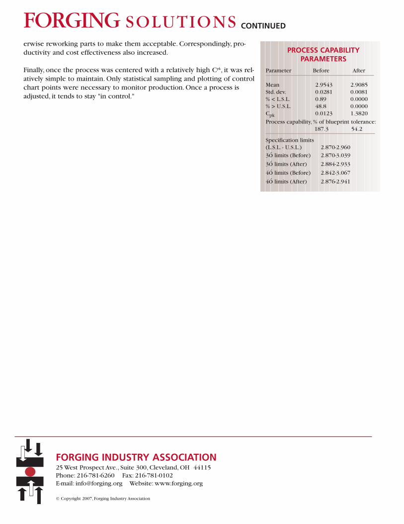
erwise reworking parts to make them acceptable. Correspondingly, pro-ductivity and cost effectiveness also increased.
Finally, once the process was centered with a relatively high Cpk, it was rel-atively simple to maintain. Only statistical sampling and plotting of controlchart points were necessary to monitor production. Once a process isadjusted, it tends to stay "in control."
PROCESS CAPABILITY PARAMETERS
Parameter Before After
Mean 2.9543 2.9085Std. dev. 0.0281 0.0081% < L.S.L. 0.89 0.0000% > U.S.L. 48.8 0.0000Cpk 0.0123 1.3820
Process capability, % of blueprint tolerance:187.3 54.2
Specification limits(L.S.L. - U.S.L.) 2.870-2.960
3ó limits (Before) 2.870-3.039
3ó limits (After) 2.884-2.933
4ó limits (Before) 2.842-3.067
4ó limits (After) 2.876-2.941
CONTINUEDFORGING SOLUTIONS
FORGING INDUSTRY ASSOCIATION25 West Prospect Ave., Suite 300, Cleveland, OH 44115Phone: 216-781-6260 Fax: 216-781-0102 E-mail: [email protected] Website: www.forging.org
© Copyright 2007, Forging Industry Association
CASE STUDY FROM THE FILES:Co-operative redesign delivered forged stop nut, eliminated machining,and consolidated parts
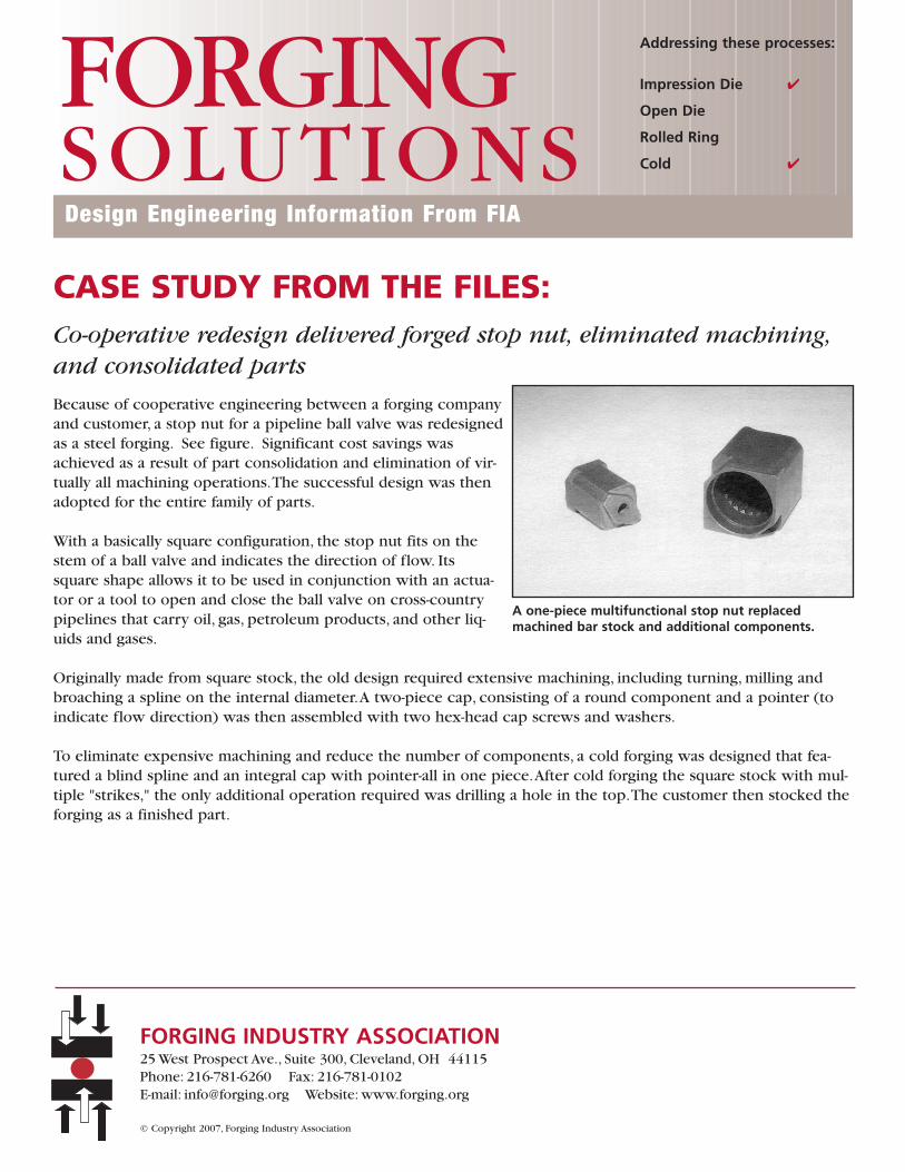
Because of cooperative engineering between a forging companyand customer, a stop nut for a pipeline ball valve was redesignedas a steel forging. See figure. Significant cost savings wasachieved as a result of part consolidation and elimination of vir-tually all machining operations.The successful design was thenadopted for the entire family of parts.
With a basically square configuration, the stop nut fits on thestem of a ball valve and indicates the direction of flow. Itssquare shape allows it to be used in conjunction with an actua-tor or a tool to open and close the ball valve on cross-countrypipelines that carry oil, gas, petroleum products, and other liq-uids and gases.
Originally made from square stock, the old design required extensive machining, including turning, milling andbroaching a spline on the internal diameter.A two-piece cap, consisting of a round component and a pointer (toindicate flow direction) was then assembled with two hex-head cap screws and washers.
To eliminate expensive machining and reduce the number of components, a cold forging was designed that fea-tured a blind spline and an integral cap with pointer-all in one piece.After cold forging the square stock with mul-tiple "strikes," the only additional operation required was drilling a hole in the top.The customer then stocked theforging as a finished part.
Design Engineering Information From FIA
FORGINGSOLUTIONS
Addressing these processes:
Impression Die
Open Die
Rolled Ring
Cold
FORGING INDUSTRY ASSOCIATION25 West Prospect Ave., Suite 300, Cleveland, OH 44115Phone: 216-781-6260 Fax: 216-781-0102 E-mail: [email protected] Website: www.forging.org
© Copyright 2007, Forging Industry Association
A one-piece multifunctional stop nut replacedmachined bar stock and additional components.
CASE STUDY FROM THE FILES:Redesign plus teamwork produced a forged part, saving 80% in material cost over casting
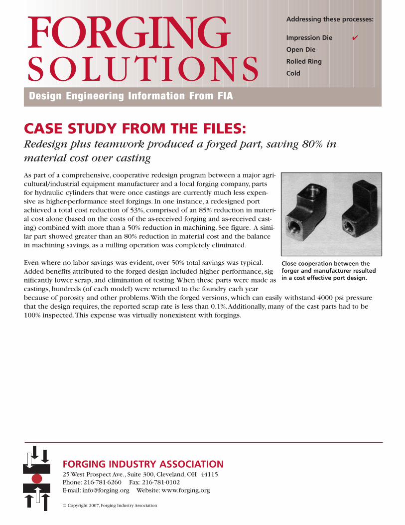
As part of a comprehensive, cooperative redesign program between a major agri-cultural/industrial equipment manufacturer and a local forging company, partsfor hydraulic cylinders that were once castings are currently much less expen-sive as higher-performance steel forgings. In one instance, a redesigned portachieved a total cost reduction of 53%, comprised of an 85% reduction in materi-al cost alone (based on the costs of the as-received forging and as-received cast-ing) combined with more than a 50% reduction in machining. See figure. A simi-lar part showed greater than an 80% reduction in material cost and the balancein machining savings, as a milling operation was completely eliminated.
Even where no labor savings was evident, over 50% total savings was typical.Added benefits attributed to the forged design included higher performance, sig-nificantly lower scrap, and elimination of testing.When these parts were made ascastings, hundreds (of each model) were returned to the foundry each yearbecause of porosity and other problems.With the forged versions, which can easily withstand 4000 psi pressurethat the design requires, the reported scrap rate is less than 0.1%.Additionally, many of the cast parts had to be100% inspected.This expense was virtually nonexistent with forgings.
Design Engineering Information From FIA
FORGINGSOLUTIONS
Addressing these processes:
Impression Die
Open Die
Rolled Ring
Cold
FORGING INDUSTRY ASSOCIATION25 West Prospect Ave., Suite 300, Cleveland, OH 44115Phone: 216-781-6260 Fax: 216-781-0102 E-mail: [email protected] Website: www.forging.org
© Copyright 2007, Forging Industry Association
Close cooperation between theforger and manufacturer resultedin a cost effective port design.
CASE STUDY FROM THE FILES:Forged-microalloyed yoke for driveline delivered net savings plusincreased performance
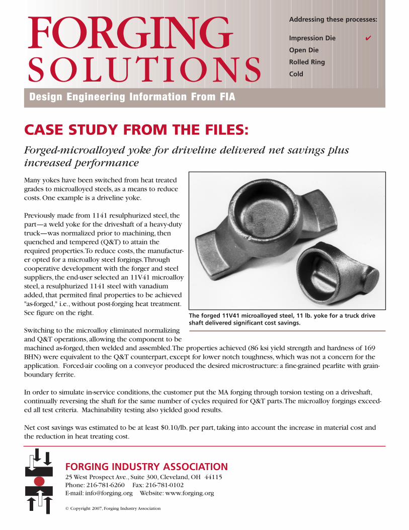
Many yokes have been switched from heat treatedgrades to microalloyed steels, as a means to reducecosts. One example is a driveline yoke.
Previously made from 1141 resulphurized steel, thepart—a weld yoke for the driveshaft of a heavy-dutytruck—was normalized prior to machining, thenquenched and tempered (Q&T) to attain therequired properties.To reduce costs, the manufactur-er opted for a microalloy steel forgings.Throughcooperative development with the forger and steelsuppliers, the end-user selected an 11V41 microalloysteel, a resulphurized 1141 steel with vanadiumadded, that permited final properties to be achieved"as-forged," i.e., without post-forging heat treatment.See figure on the right.
Switching to the microalloy eliminated normalizingand Q&T operations, allowing the component to bemachined as-forged, then welded and assembled.The properties achieved (86 ksi yield strength and hardness of 169BHN) were equivalent to the Q&T counterpart, except for lower notch toughness, which was not a concern for theapplication. Forced-air cooling on a conveyor produced the desired microstructure: a fine-grained pearlite with grain-boundary ferrite.
In order to simulate in-service conditions, the customer put the MA forging through torsion testing on a driveshaft,continually reversing the shaft for the same number of cycles required for Q&T parts.The microalloy forgings exceed-ed all test criteria. Machinability testing also yielded good results.
Net cost savings was estimated to be at least $0.10/lb. per part, taking into account the increase in material cost andthe reduction in heat treating cost.
Design Engineering Information From FIA
FORGINGSOLUTIONS
Addressing these processes:
Impression Die
Open Die
Rolled Ring
Cold
The forged 11V41 microalloyed steel, 11 lb. yoke for a truck driveshaft delivered significant cost savings.
FORGING INDUSTRY ASSOCIATION25 West Prospect Ave., Suite 300, Cleveland, OH 44115Phone: 216-781-6260 Fax: 216-781-0102 E-mail: [email protected] Website: www.forging.org
© Copyright 2007, Forging Industry Association
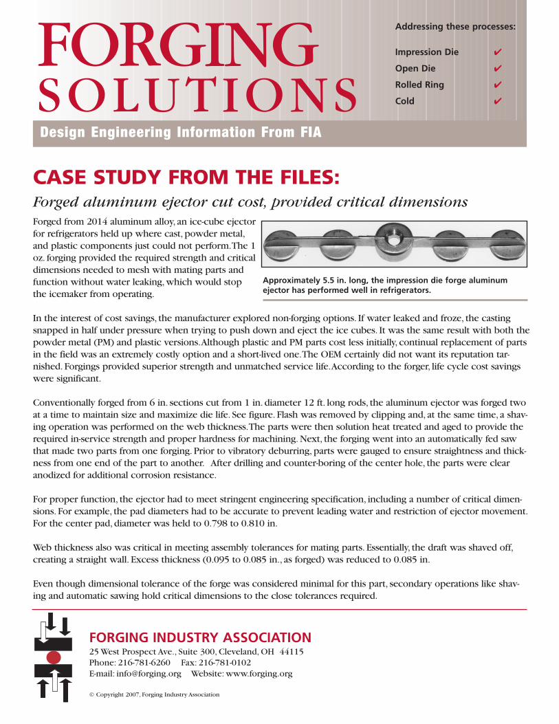
CASE STUDY FROM THE FILES:Forged aluminum ejector cut cost, provided critical dimensionsForged from 2014 aluminum alloy, an ice-cube ejectorfor refrigerators held up where cast, powder metal,and plastic components just could not perform.The 1oz. forging provided the required strength and criticaldimensions needed to mesh with mating parts andfunction without water leaking, which would stopthe icemaker from operating.
In the interest of cost savings, the manufacturer explored non-forging options. If water leaked and froze, the castingsnapped in half under pressure when trying to push down and eject the ice cubes. It was the same result with both thepowder metal (PM) and plastic versions.Although plastic and PM parts cost less initially, continual replacement of partsin the field was an extremely costly option and a short-lived one.The OEM certainly did not want its reputation tar-nished. Forgings provided superior strength and unmatched service life.According to the forger, life cycle cost savingswere significant.
Conventionally forged from 6 in. sections cut from 1 in. diameter 12 ft. long rods, the aluminum ejector was forged twoat a time to maintain size and maximize die life. See figure. Flash was removed by clipping and, at the same time, a shav-ing operation was performed on the web thickness.The parts were then solution heat treated and aged to provide therequired in-service strength and proper hardness for machining. Next, the forging went into an automatically fed sawthat made two parts from one forging. Prior to vibratory deburring, parts were gauged to ensure straightness and thick-ness from one end of the part to another. After drilling and counter-boring of the center hole, the parts were clearanodized for additional corrosion resistance.
For proper function, the ejector had to meet stringent engineering specification, including a number of critical dimen-sions. For example, the pad diameters had to be accurate to prevent leading water and restriction of ejector movement.For the center pad, diameter was held to 0.798 to 0.810 in.
Web thickness also was critical in meeting assembly tolerances for mating parts. Essentially, the draft was shaved off,creating a straight wall. Excess thickness (0.095 to 0.085 in., as forged) was reduced to 0.085 in.
Even though dimensional tolerance of the forge was considered minimal for this part, secondary operations like shav-ing and automatic sawing hold critical dimensions to the close tolerances required.
Design Engineering Information From FIA
FORGINGSOLUTIONS
Addressing these processes:
Impression Die
Open Die
Rolled Ring
Cold
Approximately 5.5 in. long, the impression die forge aluminumejector has performed well in refrigerators.
FORGING INDUSTRY ASSOCIATION25 West Prospect Ave., Suite 300, Cleveland, OH 44115Phone: 216-781-6260 Fax: 216-781-0102 E-mail: [email protected] Website: www.forging.org
© Copyright 2007, Forging Industry Association
CASE STUDY FROM THE FILES:Forging techniques made steel cam cost-effective for high-volume production
In the past, forged-steel rollercamshafts were not cost-effective fortwo reasons: 1) an extensive amountof material was required to provideproper flashing of the cam; and 2)extensive machining was required toadequately "clean up" the heavymachine stock.
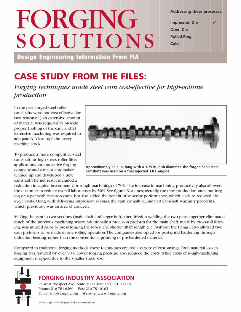
To produce a more competitive steelcamshaft for high-stress roller lifterapplications, an innovative forgingcompany and a major automakerteamed up and developed a newcamshaft.The net result included areduction in capital investment (for rough machining) of 70%.The increase in machining productivity also allowedthe customer to reduce overall labor costs by 50%. See figure. Not unexpectedly, the new production rates put forg-ing on a par with cast-iron cams, but also added the benefit of superior performance, which leads to reduced life-cycle costs.Along with delivering impressive savings, the cam virtually eliminated camshaft warranty problems,which previously was an area of concern.
Making the cam in two sections (main shaft and larger hub), then friction welding the two parts together eliminatedmuch of the previous machining waste.Additionally, a precision preform for the main shaft, made by cross-roll form-ing, was utilized prior to press forging the lobes.The shorter shaft length (i.e., without the flange) also allowed twocam preforms to be made in one rolling operation.The companies also opted for post-grind hardening throughinduction heating, rather than the conventional grinding of pre-hardened material.
Compared to traditional forging methods, these techniques created a variety of cost savings.Total material loss inforging was reduced by over 50%. Lower forging pressure also reduced die costs, while costs of rough-machiningequipment dropped due to the smaller stock size.
Approximately 15.5 in. long with a 3.75 in. hub diameter, the forged 5150 steelcamshaft was used on a fuel injected 3.8 L engine.
Design Engineering Information From FIA
FORGINGSOLUTIONS
Addressing these processes:
Impression Die
Open Die
Rolled Ring
Cold
FORGING INDUSTRY ASSOCIATION25 West Prospect Ave., Suite 300, Cleveland, OH 44115Phone: 216-781-6260 Fax: 216-781-0102 E-mail: [email protected] Website: www.forging.org
© Copyright 2007, Forging Industry Association
CASE STUDY FROM THE FILES:Forged microalloyed steel engine mount cut cost, outperformed alternatives
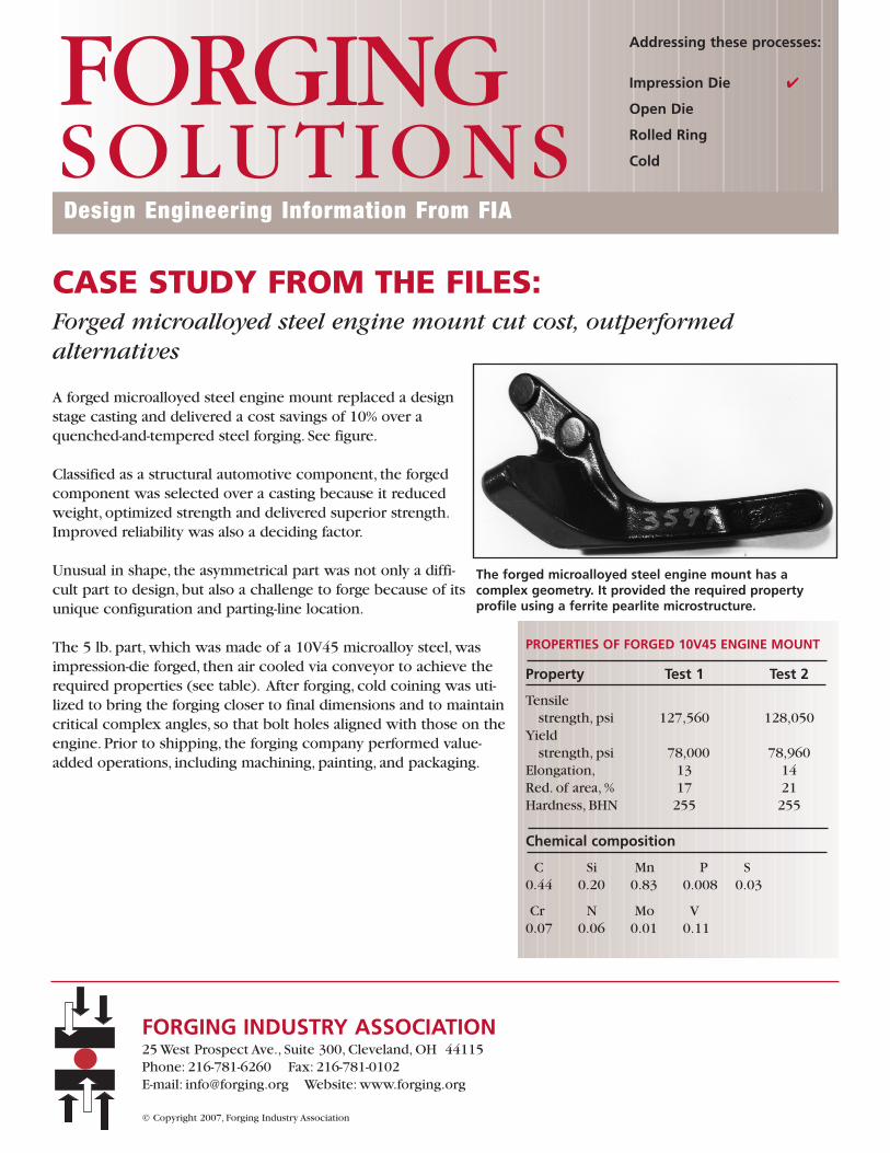
A forged microalloyed steel engine mount replaced a designstage casting and delivered a cost savings of 10% over aquenched-and-tempered steel forging. See figure.
Classified as a structural automotive component, the forgedcomponent was selected over a casting because it reducedweight, optimized strength and delivered superior strength.Improved reliability was also a deciding factor.
Unusual in shape, the asymmetrical part was not only a diffi-cult part to design, but also a challenge to forge because of itsunique configuration and parting-line location.
The 5 lb. part, which was made of a 10V45 microalloy steel, wasimpression-die forged, then air cooled via conveyor to achieve therequired properties (see table). After forging, cold coining was uti-lized to bring the forging closer to final dimensions and to maintaincritical complex angles, so that bolt holes aligned with those on theengine. Prior to shipping, the forging company performed value-added operations, including machining, painting, and packaging.
The forged microalloyed steel engine mount has a complex geometry. It provided the required property profile using a ferrite pearlite microstructure.
Design Engineering Information From FIA
FORGINGSOLUTIONS
Addressing these processes:
Impression Die
Open Die
Rolled Ring
Cold
FORGING INDUSTRY ASSOCIATION25 West Prospect Ave., Suite 300, Cleveland, OH 44115Phone: 216-781-6260 Fax: 216-781-0102 E-mail: [email protected] Website: www.forging.org
© Copyright 2007, Forging Industry Association
PROPERTIES OF FORGED 10V45 ENGINE MOUNT
Property Test 1 Test 2
Tensilestrength, psi 127,560 128,050
Yieldstrength, psi 78,000 78,960
Elongation, 13 14Red. of area, % 17 21Hardness, BHN 255 255
Chemical composition
C Si Mn P S0.44 0.20 0.83 0.008 0.03
Cr N Mo V0.07 0.06 0.01 0.11
CASE STUDY FROM THE FILES:Forged track links perform, thanks to harden-and-temper + induction
Track links can be used in a varietyof construction equipment becausethey are made of forged, heat-treatedsteel. Forging is the only manufactur-ing method that can produce proper-ties to meet design requirements.
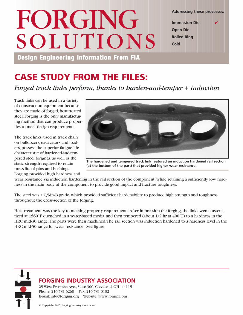
The track links, used in track chainon bulldozers, excavators and load-ers, possess the superior fatigue lifecharacteristic of hardened-and-tem-pered steel forgings, as well as thestatic strength required to retainpress-fits of pins and bushings.Forging provided high hardness and,wear resistance via induction hardening in the rail section of the component, while retaining a sufficiently low hard-ness in the main body of the component to provide good impact and fracture toughness.
The steel was a C/Mn/B grade, which provided sufficient hardenability to produce high strength and toughnessthroughout the cross-section of the forging.
Heat treatment was the key to meeting property requirements.After impression die forging, the links were austeni-tized at 1560˚F, quenched in a water-based media, and then tempered (about 1/2 hr at 400˚F) to a hardness in theHRC mid-30 range.The parts were then machined.The rail section was induction hardened to a hardness level in theHRC mid-50 range for wear resistance. See figure.
The hardened and tempered track link featured an induction hardened rail section(at the bottom of the part) that provided higher wear resistance.
Design Engineering Information From FIA
FORGINGSOLUTIONS
Addressing these processes:
Impression Die
Open Die
Rolled Ring
Cold
FORGING INDUSTRY ASSOCIATION25 West Prospect Ave., Suite 300, Cleveland, OH 44115Phone: 216-781-6260 Fax: 216-781-0102 E-mail: [email protected] Website: www.forging.org
© Copyright 2007, Forging Industry Association
CASE STUDY FROM THE FILES:Forging replaced casting in friction-welded assembly, cut cost by stream-lining manufacturing operations
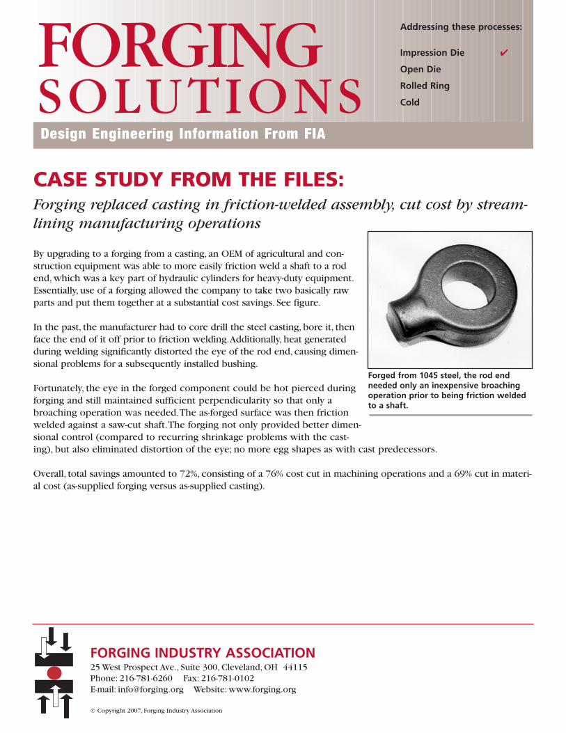
By upgrading to a forging from a casting, an OEM of agricultural and con-struction equipment was able to more easily friction weld a shaft to a rodend, which was a key part of hydraulic cylinders for heavy-duty equipment.Essentially, use of a forging allowed the company to take two basically rawparts and put them together at a substantial cost savings. See figure.
In the past, the manufacturer had to core drill the steel casting, bore it, thenface the end of it off prior to friction welding.Additionally, heat generatedduring welding significantly distorted the eye of the rod end, causing dimen-sional problems for a subsequently installed bushing.
Fortunately, the eye in the forged component could be hot pierced duringforging and still maintained sufficient perpendicularity so that only abroaching operation was needed.The as-forged surface was then frictionwelded against a saw-cut shaft.The forging not only provided better dimen-sional control (compared to recurring shrinkage problems with the cast-ing), but also eliminated distortion of the eye; no more egg shapes as with cast predecessors.
Overall, total savings amounted to 72%, consisting of a 76% cost cut in machining operations and a 69% cut in materi-al cost (as-supplied forging versus as-supplied casting).
Forged from 1045 steel, the rod endneeded only an inexpensive broachingoperation prior to being friction weldedto a shaft.
Design Engineering Information From FIA
FORGINGSOLUTIONS
Addressing these processes:
Impression Die
Open Die
Rolled Ring
Cold
FORGING INDUSTRY ASSOCIATION25 West Prospect Ave., Suite 300, Cleveland, OH 44115Phone: 216-781-6260 Fax: 216-781-0102 E-mail: [email protected] Website: www.forging.org
© Copyright 2007, Forging Industry Association