Embed Size (px)
Citation preview
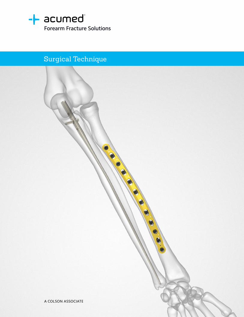
Surgical Technique
Forearm Fracture Solutions

Acumed® is a global leader of innovative orthopaedic and medical solutions.
We are dedicated to developing products, service methods, and approaches that improve patient care.
Definition
Warning Indicates critical information about a potential serious outcome to the patient or the user.
Caution Indicates instructions that must be followed in order to ensure the proper use of the device.
Note Indicates information requiring special attention.
Acumed® Forearm Fracture SolutionsAcumed Forearm Fracture Solutions includes plating and rodding systems with a range of diaphyseal radius and ulna fracture treatment options.
The plating system and rodding system may be used in combination for plating the radius and rodding the ulna, or vice versa.
By combining midshaft plates and nails for the radius and ulna, Acumed offers multiple surgical options for fractions, fusions, and osteotomies of the forearm, all in one tray.
Forearm Plate Indications for Use:Acumed Anatomic Midshaft Forearm Plates are indicated for the treatment of fractures, fusions, and osteotomies of the radius and ulna.
Forearm Rod Indications for Use:Acumed Forearm Rods are indicated for the treatment of fractures and osteotomies of the radius and ulna.

Acumed® Forearm Fracture Solutions Surgical Technique
Table of Contents
System Features . . . . . . . . . . . . . . . . . . . . . . . . . . . . . . . . . . . . . . . . . . . . . . . . . . . . . . . . . . . . . . . . 2
Instrument Overview . . . . . . . . . . . . . . . . . . . . . . . . . . . . . . . . . . . . . . . . . . . . . . . . . . . . . . . . . . . . 7
Surgical Technique Overview . . . . . . . . . . . . . . . . . . . . . . . . . . . . . . . . . . . . . . . . . . . . . . . . . . . . 10
Surgical Techniques . . . . . . . . . . . . . . . . . . . . . . . . . . . . . . . . . . . . . . . . . . . . . . . . . . . . . . . . . . . . 12
Anatomic Midshaft Forearm Plate Surgical Technique . . . . . . . . . . . . . . . . . . . . . . . . . . . . 12
Ulna Rod Surgical Technique . . . . . . . . . . . . . . . . . . . . . . . . . . . . . . . . . . . . . . . . . . . . . . . . . 15
Radius Rod Surgical Technique . . . . . . . . . . . . . . . . . . . . . . . . . . . . . . . . . . . . . . . . . . . . . . . 19
Ordering Information . . . . . . . . . . . . . . . . . . . . . . . . . . . . . . . . . . . . . . . . . . . . . . . . . . . . . . . . . . .23

2
System FeaturesPlates
Acumed® Forearm Fracture Solutions Surgical Technique
Tapered endsAre designed to reduce stress on bone and minimize the potential for refracture above or below the plate
Limited contact undersurfaceDesigned to ease compression of the periosteum to improve blood supply to the healing zone
Acumed Anatomic Midshaft Forearm Plates offer features not found in traditional straight plates. The system of precontoured plates, including Midshaft Ulna Plates, Volar Midshaft Plates, and Dorsolateral Midshaft Radius Plates, may be used to treat fractures, fusions, and osteotomies of the radius and ulna.
When used as templates, precontoured plates are intended to help restore forearm geometry and assist in reestablishing pronation and supination. Precontoured plates and rods are designed to help restore radial bow and may reduce the need for intraoperative bending, thereby reducing the risk of implant weakening that may come with bending of traditional implants.
Note: The plates may be used with either the Acumed cortical (hex) or hexalobe screws.
Low-profile designScrews sit flush with the plate. This design is intended to minimize soft tissue irritation
Approach-specific radius platesFor either a dorsolateral or volar approach

Midshaft Volar Radius Plates
Midshaft Ulna Plates
Dorsolateral Midshaft Radius Plates
6-Hole Midshaft Volar Radius Plate (80 mm)(70-0066)
8-Hole Midshaft Volar Radius Plate (100 mm)(70-0067)
10-Hole Midshaft Volar Radius Plate (130 mm)(70-0068)
12-Hole MIdshaft Volar Radius Plate (160 mm)(70-0069)
14-Hole Volar Midshaft Radius Plate (180 mm)(70-0469-S*)
16-Hole Volar Midshaft Radius Plate (210 mm)(70-0470-S*)
16-Hole Midshaft Ulna Plate (210 mm)(70-0464-S*)
14-Hole Midshaft Ulna Plate (180 mm)(70-0463-S*)
12-Hole Midshaft Ulna Plate (160 mm)(70-0073)
10-Hole Midshaft Ulna Plate (130 mm)(70-0072)
8-Hole Midshaft Ulna Plate (100 mm)(70-0071)
6-Hole Midshaft Ulna Plate (80 mm)(70-0070)
6-Hole Dorsolateral Midshaft Radius Plate (80 mm)(70-0074)
8-Hole Dorsolateral Midshaft Radius Plate (100 mm)(70-0075)
10-Hole Dorsolateral Midshaft Radius Plate (130 mm)(70-0076)
12-Hole Dorsolateral Midshaft Radius Plate (160 mm)(70-0077)
14-Hole Midshaft Dorsolateral Radius Plate (180 mm)(70-0466-S*)
16-Hole Midshaft Dorsolateral Radius Plate (210 mm)(70-0467-S*)
*Optional, sterile-packed only
Acumed® Forearm Fracture Solutions Surgical Technique
3
System Features [continued]
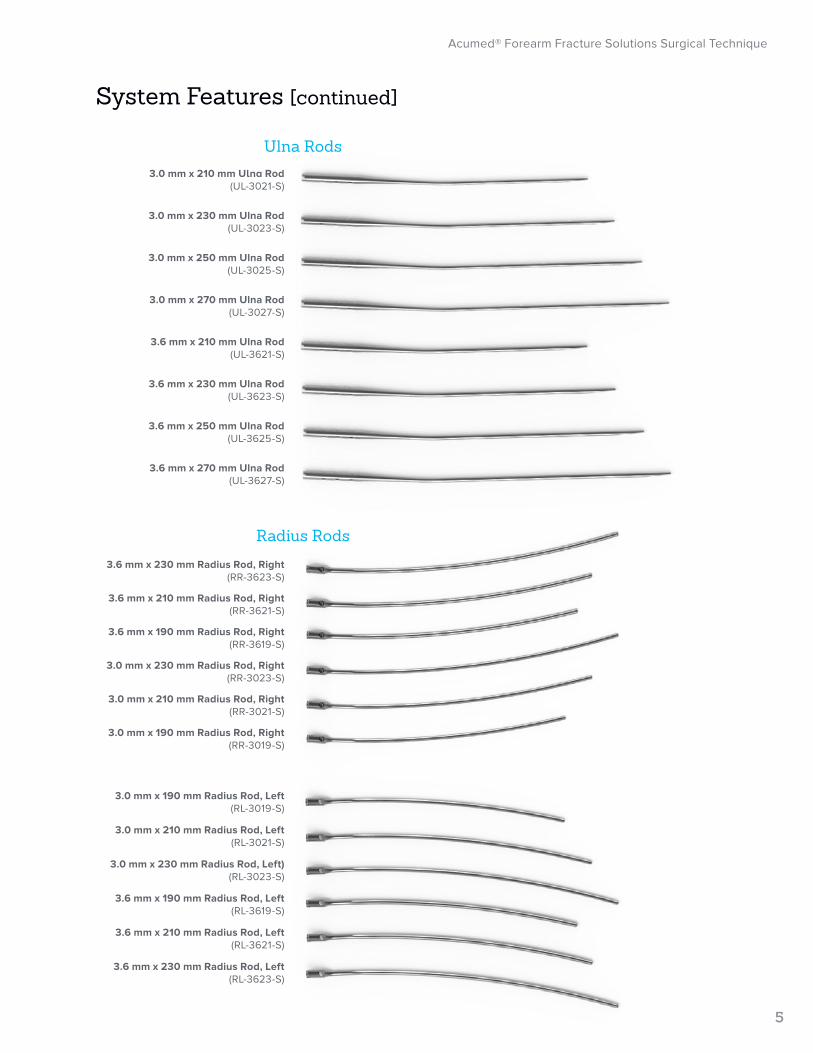
3.0 mm x 210 mm Ulna Rod(UL-3021-S)
3.6 mm x 210 mm Radius Rod, Left(RL-3621-S)
3.6 mm x 190 mm Radius Rod, Left(RL-3619-S)
3.6 mm x 230 mm Radius Rod, Left(RL-3623-S)
3.0 mm x 230 mm Ulna Rod(UL-3023-S)
3.0 mm x 230 mm Radius Rod, Left)(RL-3023-S)
3.0 mm x 250 mm Ulna Rod(UL-3025-S)
3.0 mm x 210 mm Radius Rod, Left(RL-3021-S)
3.0 mm x 270 mm Ulna Rod(UL-3027-S)
3.0 mm x 190 mm Radius Rod, Left(RL-3019-S)
3.0 mm x 190 mm Radius Rod, Right(RR-3019-S)
3.0 mm x 210 mm Radius Rod, Right(RR-3021-S)
3.0 mm x 230 mm Radius Rod, Right(RR-3023-S)
3.6 mm x 190 mm Radius Rod, Right(RR-3619-S)
3.6 mm x 210 mm Radius Rod, Right(RR-3621-S)
3.6 mm x 210 mm Ulna Rod(UL-3621-S)
3.6 mm x 230 mm Ulna Rod(UL-3623-S)
3.6 mm x 250 mm Ulna Rod(UL-3625-S)
3.6 mm x 270 mm Ulna Rod(UL-3627-S)
3.6 mm x 230 mm Radius Rod, Right(RR-3623-S)
Acumed® Forearm Fracture Solutions Surgical Technique
4
System Features [continued]Rods
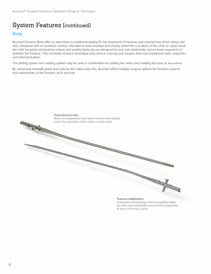
Acumed Forearm Rods offer an alternative to traditional plating for the treatment of fractures and osteotomies of the radius and ulna. Designed with an anatomic contour intended to ease insertion and closely match the curvature of the ulnar or radial canal, the rods’ targeted interlocking screws and paddle-blade tip are designed to lock and rotationally secure bone segments to stabilize the fracture. This minimally invasive technique may reduce scarring and surgery time over traditional open reduction and internal fixation.
The plating system and rodding system may be used in combination for plating the radius and rodding the ulna, or vice versa.
By combining midshaft plates and nails for the radius and ulna, Acumed offers multiple surgical options for fractions, fusions, and osteotomies of the forearm, all in one tray.
Precontoured rodsRods are designed to help ease insertion and closely match the geometry of the radial or ulnar canal
Fracture stabilizationA targeted interlocking screw and paddle-blade tip locks and rotationally secures bone fragments to assist in fracture union
3.0 mm x 210 mm Ulna Rod(UL-3021-S)
3.6 mm x 210 mm Radius Rod, Left(RL-3621-S)
3.6 mm x 190 mm Radius Rod, Left(RL-3619-S)
3.6 mm x 230 mm Radius Rod, Left(RL-3623-S)
3.0 mm x 230 mm Ulna Rod(UL-3023-S)
3.0 mm x 230 mm Radius Rod, Left)(RL-3023-S)
3.0 mm x 250 mm Ulna Rod(UL-3025-S)
3.0 mm x 210 mm Radius Rod, Left(RL-3021-S)
3.0 mm x 270 mm Ulna Rod(UL-3027-S)
3.0 mm x 190 mm Radius Rod, Left(RL-3019-S)
3.0 mm x 190 mm Radius Rod, Right(RR-3019-S)
3.0 mm x 210 mm Radius Rod, Right(RR-3021-S)
3.0 mm x 230 mm Radius Rod, Right(RR-3023-S)
3.6 mm x 190 mm Radius Rod, Right(RR-3619-S)
3.6 mm x 210 mm Radius Rod, Right(RR-3621-S)
3.6 mm x 210 mm Ulna Rod(UL-3621-S)
3.6 mm x 230 mm Ulna Rod(UL-3623-S)
3.6 mm x 250 mm Ulna Rod(UL-3625-S)
3.6 mm x 270 mm Ulna Rod(UL-3627-S)
3.6 mm x 230 mm Radius Rod, Right(RR-3623-S)
Ulna Rods
Radius Rods
Acumed® Forearm Fracture Solutions Surgical Technique
5
System Features [continued]

6
System Features [continued]Instrumentation
Acumed® Forearm Fracture Solutions Surgical Technique
Forearm Fracture Solutions includes several instruments designed to streamline the surgical experience.
Customized Plate Clamps ⊲ One end shaped to fit over and grasp the plate ⊲ Opposing end has serrated teeth to grip the bone to maintain plate placement and reduction ⊲ Fit of the clamp is intended to help position the plate on the bone and avoid scratching of the plate that can be caused by a
traditional clamp’s serrated jaw closing down on the plate
Angled Drill Guide (Optional) ⊲ Allows the surgeon to angle the drill at three predetermined angles: 15, 30, and 45 degrees. Surgeons may lag across the
fracture site through the plate or prior to plate application ⊲ Contains K-wire holes for visualization of the screw’s trajectory and placement in the bone
Soft Tissue Spreader ⊲ Attaches to the locking holes in the plate and holds the soft tissue away from the surgical site ⊲ Allows fewer retractors and instruments in the surgical site ⊲ K-wire holes secure spreader to the plate for alignment if the locking bolt is not used
Soft Tissue Spreader
Plate Clamps Angled Drill Guide

Reduction Forceps with Serrated Jaws(PL-CL04)
2.8 mm Quick Release Drill(80-0387) 3.5 mm Cortical Screw
Bone Tap(MS-LTT35)
Hexalobe Locking Drill Guide 6–65 mm(80-0668)
2.8 mm/3.5 mm Thin Drill Guide(PL-2196)
3.5 mm Narrow Drill Guide Cannula(PL-2095)
2.8 mm x 5" Quick Release Drill(MS-DC28)
Depth Gauge 6–65 mm(80-0623)
3.0 mm x 5" Quick Release Drill(80-1088)
Plate Clamp(80-0223)
2.3 mm Quick Release Drill(80-0627)
3.5 mm x 5" Quick Release Drill(MS-DC35)
Acumed® Forearm Fracture Solutions Surgical Technique
7
Instrument Overview
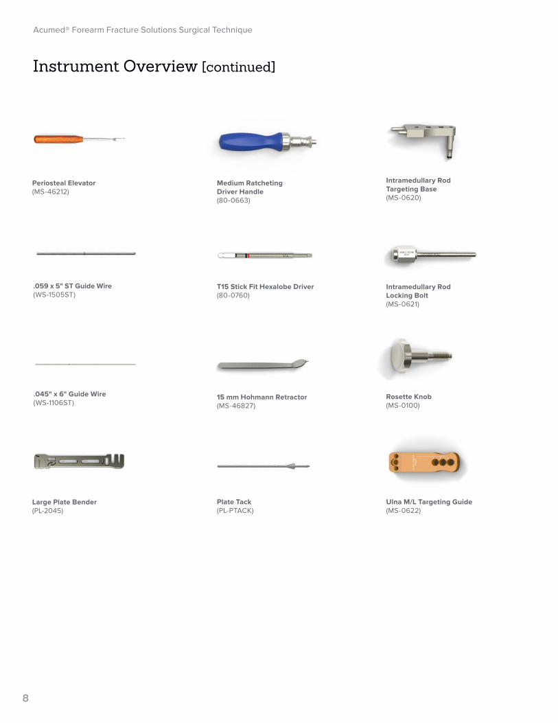
Intramedullary Rod Locking Bolt(MS-0621)
Rosette Knob(MS-0100)
Ulna M/L Targeting Guide(MS-0622)
Intramedullary Rod Targeting Base(MS-0620)
.045" x 6" Guide Wire(WS-1106ST)
Large Plate Bender(PL-2045)
Periosteal Elevator(MS-46212)
Plate Tack(PL-PTACK)
.059 x 5" ST Guide Wire(WS-1505ST)
Medium Ratcheting Driver Handle(80-0663)
T15 Stick Fit Hexalobe Driver(80-0760)
15 mm Hohmann Retractor(MS-46827)
8
Acumed® Forearm Fracture Solutions Surgical Technique
Instrument Overview [continued]
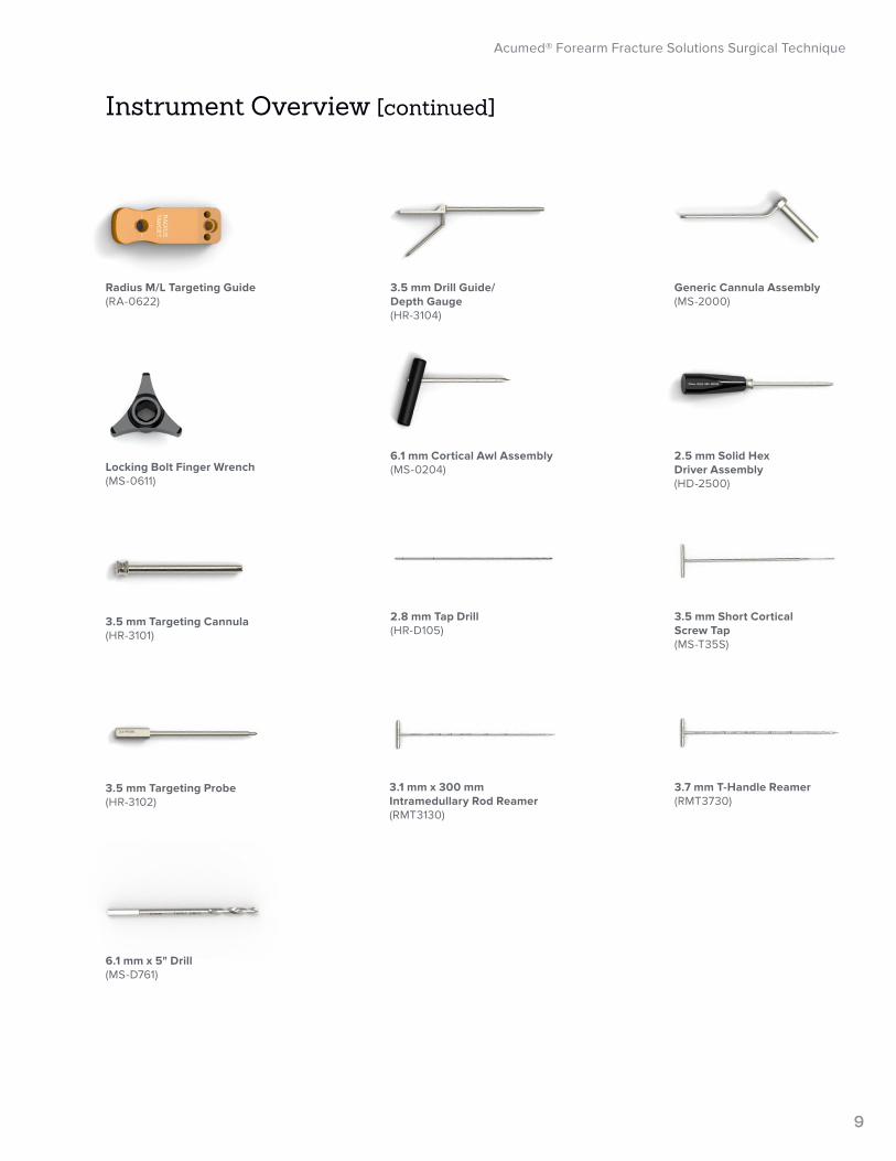
Locking Bolt Finger Wrench(MS-0611)
3.5 mm Targeting Probe(HR-3102)
6.1 mm x 5" Drill(MS-D761)
3.5 mm Drill Guide/ Depth Gauge(HR-3104)
6.1 mm Cortical Awl Assembly(MS-0204)
2.8 mm Tap Drill(HR-D105)
Generic Cannula Assembly(MS-2000)
2.5 mm Solid Hex Driver Assembly(HD-2500)
3.7 mm T-Handle Reamer(RMT3730)
Radius M/L Targeting Guide(RA-0622)
3.5 mm Targeting Cannula(HR-3101)
3.5 mm Short Cortical Screw Tap(MS-T35S)
3.1 mm x 300 mm Intramedullary Rod Reamer(RMT3130)
9
Acumed® Forearm Fracture Solutions Surgical Technique
Instrument Overview [continued]

Exposure and Fracture Reduction
Plate Selection and Placement
Nonlocking Screw Insertion
10
Acumed® Forearm Fracture Solutions Surgical Technique
Surgical Technique Overview
Anatomic Midshaft Forearm Plate Surgical Technique
Assemble Targeting Guide
Assemble Targeting Guide
Preoperative Planning and Evaluation
Preoperative Planning and Evaluation
Surgical Approach and Cortex Perforation
Surgical Approach and Cortex Perforation
Radius Rod Surgical Technique
Ulna Rod Surgical Technique

Locking Screw Insertion
Postoperative Protocol
Fracture Site Compression
11
Acumed® Forearm Fracture Solutions Surgical Technique
Interlocking Screw Insertion
Interlocking Screw Insertion
Implant Insertion
Implant Insertion
Canal Preparation and Rod Selection
Canal Preparation and Rod Selection

12
Acumed® Forearm Fracture Solutions Surgical Technique
Surgical Spreader(80-0251)
Surgical Spreader Locking Bolt(80-0252)
Reduction Forceps with Serrated Jaw(PL-CL04)
Plate Clamp (80-0223)
.045" x 6" ST Guide Wire (WS-1106ST)Also used as a K-wire
Plate Tack (PL-PTACK)
Figure 1
Anatomic Midshaft Forearm Plate Surgical Technique
1 Exposure and Fracture ReductionExpose the surgical site according to the surgeon's
preference, using either the anterior approach or the posterolateral approach for the radius, depending on the plate to be used for fixation. Ulnar fixation may be achieved through the standard approach, following the subcutaneous border of the ulna. If both the radius and the ulna are fractured, reduce the bone with the simpler fracture first.1
Note: A lag screw may be placed across the fracture site prior to plate application or through the plate in a later step.
1. Heim D, Luria S, Mosheiff R, Weil Y. AO surgery reference: forearm approach. AO Foundation website. www2.aofoundation.org. Accessed Feb. 10, 2017.
2 Plate Selection and PlacementUse fracture assessment and/or preoperative X-ray
templating to determine appropriate plate length.
Place the selected plate onto the bone with the middle of the plate positioned over the fracture site to optimize compression.
Use Plate Tacks (PL-PTACK), Plate Clamps (80-0223), Reduction Forceps with Serrated Jaw (PL-CL04), or .045" x 6" ST K-wires (WS-1106ST) to aid with provisional plate fixation if necessary.
Optional: Thread the Surgical Spreader (Plate Mounted) (80-0251) into one of the locking holes in the plate with the Surgical Spreader Locking Bolt (80-0252) to aid with visibility of the surgical site.
Note: Instrument availability may vary depending on which iteration of tray is supplied.
*Note: 14- and 16-hole plates are sterile-packed. Use a ruler and the plate length table to the left as a reference to determine if longer plates should be used.
Figure 2
Plate Lengths
Number of Holes Length (mm)
6 80
8 100
10 130
12 160
14* 180
16* 210

3.5 mm Narrow Drill Guide Cannula(PL-2095)
13
Acumed® Forearm Fracture Solutions Surgical Technique
2.8 mm Quick Release Drill(80-0387)
Angled Drill Guide (80-0204)
3.0 or 3.5 mm Nonlocking Hexalobe Screw (30-0XXX)
3.5 mm Short Cortical Screw Tap(MS-T35S)
Anatomic Midshaft Forearm Plate Surgical Technique [continued]
3 Nonlocking Screw InsertionInsert a 3.0 or 3.5 mm Nonlocking Hexalobe Screw
(30-0XXX) to ensure compression in the axial plane. It is recommended these screws be implanted bicortically for optimal fixation.
Use a 2.8 mm Quick Release Drill (80-0387) and appropriate drill guide for both neutral and dynamic compression drilling.
Insert screws by alternating from one side of the fracture to the other.
Check forearm rotation regularly throughout the procedure.
Optional: The Angled Drill Guide (80-0204) may be used to angle the drill at 15, 30, or 45 degree angles if desired. K-wire holes are also included in the drill guide for additional visualization of screw trajectory and bone placement.
Note: Cortical (hex) or hexalobe screws can be used in the Anatomic Midshaft Forearm Plate System. If dense bone is encountered, use the 3.5 mm Short Cortical Screw Tap (MS-T35S) prior to implanting screws.
4 Fracture Site CompressionUsing the gold end of the 3.5 mm Narrow Drill Guide
Cannula (PL-2095), drill in dynamic compression mode to provide compression at the fracture site.
Insert at least three 3.0 or 3.5 mm Nonlocking Hexalobe Screws (30-0XXX) on each side of the fracture.
Figure 3
Figure 4
Figure 5
14
Acumed® Forearm Fracture Solutions Surgical Technique
T15 Stick Fit Hexalobe Driver (80-0760)
Medium Ratcheting Driver Handle (80-0663)
3.5 mm Locking Hexalobe Screw(30-023X)
3.5 mm Cortical Screw(CO-3XXX-S)
Figure 6
Anatomic Midshaft Forearm Plate Surgical Technique [continued]
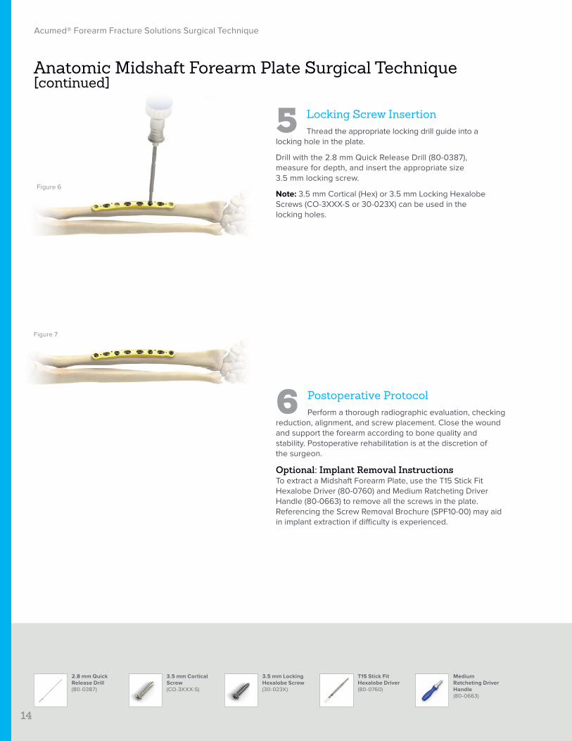
5 Locking Screw InsertionThread the appropriate locking drill guide into a
locking hole in the plate.
Drill with the 2.8 mm Quick Release Drill (80-0387), measure for depth, and insert the appropriate size 3.5 mm locking screw.
Note: 3.5 mm Cortical (Hex) or 3.5 mm Locking Hexalobe Screws (CO-3XXX-S or 30-023X) can be used in the locking holes.
6 Postoperative ProtocolPerform a thorough radiographic evaluation, checking
reduction, alignment, and screw placement. Close the wound and support the forearm according to bone quality and stability. Postoperative rehabilitation is at the discretion of the surgeon.
Optional: Implant Removal InstructionsTo extract a Midshaft Forearm Plate, use the T15 Stick Fit Hexalobe Driver (80-0760) and Medium Ratcheting Driver Handle (80-0663) to remove all the screws in the plate. Referencing the Screw Removal Brochure (SPF10-00) may aid in implant extraction if difficulty is experienced.
Figure 7
2.8 mm Quick Release Drill(80-0387)

15
Acumed® Forearm Fracture Solutions Surgical Technique
Ulna Rod Surgical Technique
Ulna M/L Targeting Guide(MS-0622)
Rosette Knob(MS-0100)
Intramedullary Rod Targeting Base(MS-0620)
Intramedullary Rod Locking Bolt(MS-0621)
Locking Bolt Finger Wrench(MS-0611)
Ulna Rod(UL-3XXX-S)
Figure 1
1 Preoperative Planning and EvaluationEvaluate positioning of the fracture(s) using fluoroscopy.
It may be necessary to reference the uninjured ulna to more accurately estimate screw length.
Place the patient in a supine position. A radiolucent arm board should be used. Alternatively a lateral position can be used, bringing the arm over the patient’s torso.
Implant the Ulna Rod (UL-3XXX-S) under fluoroscopy to evaluate the position of the rod and the screw. Radiographs in both the anterior to posterior (A/P) and medial to lateral (M/L) planes are suggested.
2 Assemble Targeting GuideTo assemble the targeting guide, first slide the
Intramedullary Rod Locking Bolt (MS-0621) through the Intramedullary Rod Targeting Base (MS-0620), then thread it into the rod.
Align the laser mark on the base plate barrel with the corresponding laser mark on the proximal end of the Ulna Rod. This will ensure proper orientation when implanting the rod.
Tighten the locking bolt with the Locking Bolt Finger Wrench (MS-0611). Slide the Ulna M/L Targeting Guide (MS-0622) onto the base plate pins. Lock it into place with a Rosette Knob (MS-0100).
Figure 2

16
Acumed® Forearm Fracture Solutions Surgical Technique
Generic Cannula Assembly(MS-2000)
Ulna Rod Surgical Technique [continued]
3.1 mm x 300 mm Intramedullary Rod Reamer(RMT3130)
3.7 mm T-Handle Reamer(RMT3730)
6.1 mm Cortical Awl Assembly(MS-0204)
Figure 3
Figure 5
3 Surgical Approach and Cortex Perforation
The method for approaching the insertion site is at the surgeon's discretion and may be altered based on the individual patient's anatomy. The following technique may be used as an approach:
Make a 1–2 cm incision longitudinally along the tip of the olecranon to expose the implant entry site.
Carry dissection down sharply through the subcutaneous tissues and the triceps tendon. Care should be taken to avoid the ulnar nerve that sits medially to the olecranon.
Establish the implant insertion point by using the 6.1 mm Cortical Awl Assembly (MS-0204) to perforate the cortex. The Generic Cannula Assembly (MS-2000) may be used in conjunction with the awl as a tissue protector.
Start the awl in the center of the olecranon process, directly in line with the proximal intramedullary canal of the ulna. Bury the awl to the depth groove on the shaft labeled “ULNA.” Fluoroscopy is helpful when verifying proper alignment within the intramedullary canal.
4 Canal Preparation and Rod SelectionReam the diaphyseal canal with the 3.1 mm x 300 mm
Intramedullary Rod Reamer (RMT3130) and, if necessary to achieve desired cortical engagement, use the 3.7 mm T-Handle Reamer (RMT3730). Start with the smaller reamer to avoid over-reaming. Rod length can be read directly off of the side of the reamer handle labeled “ULNA” (shown).
Note: Select a rod diameter that will pass down the canal with minimal reaming. Choosing a diameter that is too large may cause the rod to become impacted during insertion and difficult to remove.
The reamer should always be used to ensure that the rod will pass down the canal without becoming impacted upon insertion.
Figure 4
17
Acumed® Forearm Fracture Solutions Surgical Technique
Ulna Rod Surgical Technique [continued]
Ulna Rod(UL-3XXX-S)
Figure 6
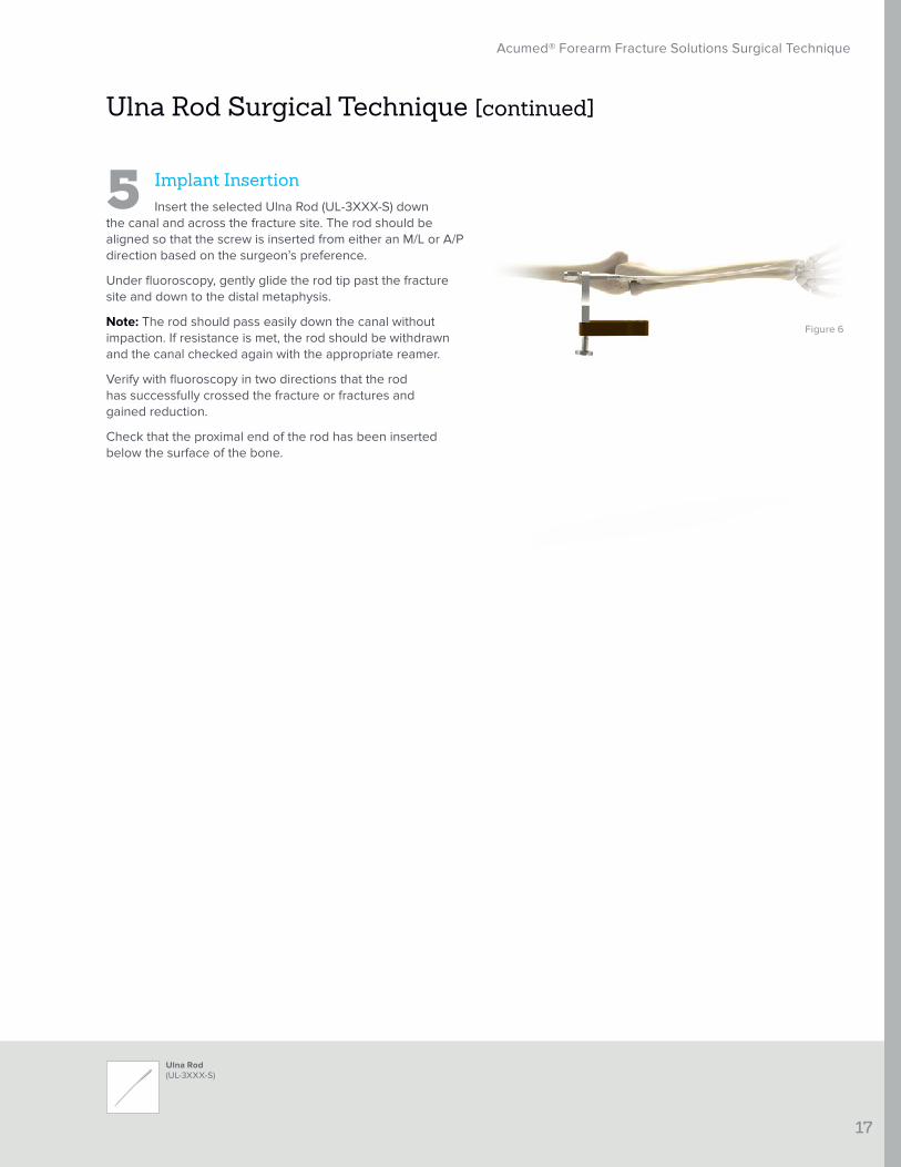
5 Implant InsertionInsert the selected Ulna Rod (UL-3XXX-S) down
the canal and across the fracture site. The rod should be aligned so that the screw is inserted from either an M/L or A/P direction based on the surgeon’s preference.
Under fluoroscopy, gently glide the rod tip past the fracture site and down to the distal metaphysis.
Note: The rod should pass easily down the canal without impaction. If resistance is met, the rod should be withdrawn and the canal checked again with the appropriate reamer.
Verify with fluoroscopy in two directions that the rod has successfully crossed the fracture or fractures and gained reduction.
Check that the proximal end of the rod has been inserted below the surface of the bone.
18
Acumed® Forearm Fracture Solutions Surgical Technique
3.5 mm Cortical Screw(CO-3XXX-S)
2.5 mm Solid Hex Driver Assembly(HD-2500)
3.5 mm Short Cortical Screw Tap(MS-T35S)
3.5 mm Drill Guide/ Depth Gauge(HR-3104)
Intramedullary Locking Bolt (MS-0621)
3.5 mm Targeting Probe(HR-3102)
2.8 mm Tap Drill(HR-D105)
3.5 mm Targeting Cannula(HR-3101)
Figure 7
Ulna Rod Surgical Technique [continued]
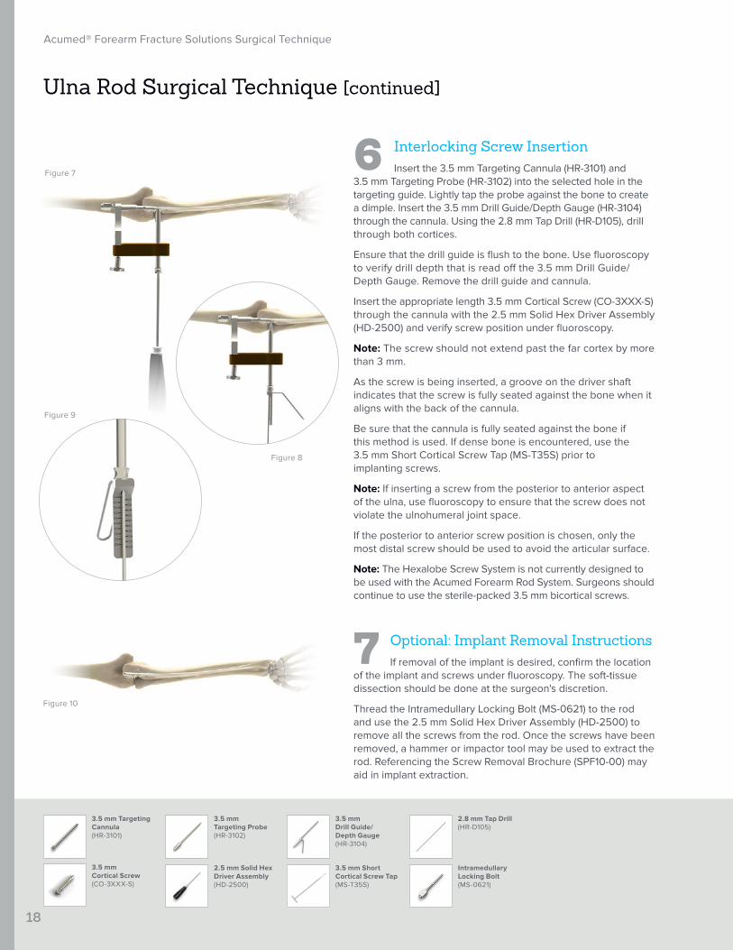
6 Interlocking Screw InsertionInsert the 3.5 mm Targeting Cannula (HR-3101) and
3.5 mm Targeting Probe (HR-3102) into the selected hole in the targeting guide. Lightly tap the probe against the bone to create a dimple. Insert the 3.5 mm Drill Guide/Depth Gauge (HR-3104) through the cannula. Using the 2.8 mm Tap Drill (HR-D105), drill through both cortices.
Ensure that the drill guide is flush to the bone. Use fluoroscopy to verify drill depth that is read off the 3.5 mm Drill Guide/ Depth Gauge. Remove the drill guide and cannula.
Insert the appropriate length 3.5 mm Cortical Screw (CO-3XXX-S) through the cannula with the 2.5 mm Solid Hex Driver Assembly (HD-2500) and verify screw position under fluoroscopy.
Note: The screw should not extend past the far cortex by more than 3 mm.
As the screw is being inserted, a groove on the driver shaft indicates that the screw is fully seated against the bone when it aligns with the back of the cannula.
Be sure that the cannula is fully seated against the bone if this method is used. If dense bone is encountered, use the 3.5 mm Short Cortical Screw Tap (MS-T35S) prior to implanting screws.
Note: If inserting a screw from the posterior to anterior aspect of the ulna, use fluoroscopy to ensure that the screw does not violate the ulnohumeral joint space.
If the posterior to anterior screw position is chosen, only the most distal screw should be used to avoid the articular surface.
Note: The Hexalobe Screw System is not currently designed to be used with the Acumed Forearm Rod System. Surgeons should continue to use the sterile-packed 3.5 mm bicortical screws.
7 Optional: Implant Removal InstructionsIf removal of the implant is desired, confirm the location
of the implant and screws under fluoroscopy. The soft-tissue dissection should be done at the surgeon's discretion.
Thread the Intramedullary Locking Bolt (MS-0621) to the rod and use the 2.5 mm Solid Hex Driver Assembly (HD-2500) to remove all the screws from the rod. Once the screws have been removed, a hammer or impactor tool may be used to extract the rod. Referencing the Screw Removal Brochure (SPF10-00) may aid in implant extraction.
Figure 8
Figure 9
Figure 10

Radius M/L Targeting Guide(RA-0622)
Rosette Knob(MS-0100)
19
Acumed® Forearm Fracture Solutions Surgical Technique
Intramedullary Rod Targeting Base(MS-0620)
Locking Bolt Finger Wrench(MS-0611)
Intramedullary Rod Locking Bolt(MS-0621)
Radius Rod(RX-3XXX-S)
Radius Rod Surgical Technique
Figure 1
Figure 2
1 Preoperative Planning and EvaluationEvaluate positioning of the fracture(s) using
fluoroscopy. It may be necessary to reference the uninjured radius to more accurately estimate screw length.
Place the patient in a supine position. A radiolucent arm board should be used. Alternatively a lateral position can be used, bringing the arm over the patient’s torso.
Implant the Radius Rod (RX-3XXX-S) under fluoroscopy to evaluate the position of the rod and the screw. Radiographs in both the anterior to posterior (A/P) and medial to lateral (M/L) planes are suggested.
2 Assemble Targeting GuideTo assemble the targeting guide, first slide the
Intramedullary Rod Locking Bolt (MS-0621) through the Intramedullary Rod Targeting Base (MS-0620) then thread it into the rod.
Align the laser mark on the base plate barrel with the corresponding laser mark on the distal end of the Radius Rod (RX-3XXX). This will ensure proper orientation when implanting the rod.
Tighten the Intramedullary Rod Locking Bolt with the Locking Bolt Finger Wrench (MS-0611). Slide the Radius M/L Targeting Guide (RA-0622) onto the base plate pins.
Lock the construct into place with a Rosette Knob (MS-0100).

20
Acumed® Forearm Fracture Solutions Surgical Technique
3.7 mm T-Handle Reamer(RMT3730)
3.1 mm x 300 mm Intramedullary Rod Reamer(RMT3130)
Radius Rod Surgical Technique [continued]
6.1 mm Cortical Awl Assembly(MS-0204)
Generic Cannula Assembly(MS-2000)
Figure 3
Figure 5
3 Surgical Approach and Cortex Perforation
The method for approaching the insertion site is at the surgeon's discretion and may be altered based on the individual patient's anatomy. The following technique may be used for the surgical approach.
Make a 2–3 cm incision longitudinally along the distal radius over the fourth extensor compartment to expose the implant entry site. Carry dissection down bluntly through the subcutaneous tissues.
Establish the implant insertion point by using the 6.1 mm Cortical Awl Assembly (MS-0204) and the Generic Cannula Assembly (MS-2000) to perforate the cortex just ulnar to Lister’s tubercle, approximately 5 mm from the articular surface.
Direct the awl down the canal and insert to the first depth groove labeled “RADIUS.” Care should be taken to avoid accidental penetration of the adjacent cortex.
Avoid penetrating the far cortex of the radius when using the awl.
Use the Generic Cannula Assembly in conjunction with the awl as a tissue protector if necessary. Fluoroscopy is helpful when verifying proper alignment of the rod.
4 Canal Preparation and Rod SelectionReam the diaphyseal canal with the 3.1 mm x 300 mm
Intramedullary Rod Reamer (RMT3130) and, if necessary to achieve desired cortical engagement, use the 3.7 mm T-Handle Reamer (RMT3730). Start with the smaller reamer to avoid over-reaming. Rod length can be read directly off of the side of the Reamer Handle labeled “RADIUS.”
Note: The reamer should always be used to ensure that the rod will pass down the canal without becoming impacted upon insertion.
Figure 4

21
Acumed® Forearm Fracture Solutions Surgical Technique
Radius Rod(RX-3XXX-S)
Radius Rod Surgical Technique [continued]
5 Implant InsertionInsert the Radius Rod (RX-3XXX-S) down the canal
and across the fracture site. The rod should be aligned so that the screw is inserted from a dorsal-to-volar direction.
Under fluoroscopy, gently glide the rod tip past the fracture site and up to the proximal metaphysis.
Note: The rod should pass easily down the canal without impaction. If resistance is met, the rod should be withdrawn and the canal checked again with the appropriate reamer.
Verify under fluoroscopy in two directions that the rod has successfully crossed the fracture or fractures and gained reduction. Check that the distal end of the rod has been inserted below the surface of the bone.
Figure 6

22
Acumed® Forearm Fracture Solutions Surgical Technique
Radius Rod Surgical Technique [continued]
6 Interlocking Screw InsertionInsert the 3.5 mm Targeting Cannula (HR-3101)
and 3.5 mm Targeting Probe (HR-3102) into the targeting guide hole.
Lightly tap the probe against the bone to create a dimple. Insert the 3.5 mm Drill Guide/Depth Gauge (HR-3104) through the cannula. Using the 2.8 mm Tap Drill (HR-D105), drill through both cortices. Ensure that the drill guide is flush to the bone. Use fluoroscopy to verify drill depth that is read off the drill guide.
Remove the drill guide and cannula. Insert the appropriate length 3.5 mm Cortical Screw (CO-3XXX-S) through the cannula with the 2.5 mm Solid Hex Driver Assembly (HD-2500).
Note: Verify screw position under fluoroscopy. The screw should not extend past the volar cortex by more than 3 mm.
As the screw is being inserted, a groove on the driver shaft indicates that the screw is fully seated against the bone when it aligns with the back of the cannula.
Be sure that the cannula is fully seated against the bone if this method is used. If dense bone is encountered, use the 3.5 mm Short Cortical Screw Tap (MS-T35S) prior to implanting screws.
Note: The Hexalobe Screw System is not currently designed to be used with the Acumed Forearm Rod System. Surgeons should continue to use the sterile-packed 3.5 mm bicortical screws.
7 Optional: Implant Removal Instructions
If removal of the implant is desired, confirm the location of the implant and screws under fluoroscopy. The soft-tissue dissection should be done at the surgeon's discretion.
Thread the Intramedullary Locking Bolt (MS-0621) to the rod and use the 2.5 mm Solid Hex Driver Assembly (HD-2500) to remove all the screws from the rod. Once the screws have been removed, a hammer or impactor tool may be used to extract the rod. Referencing the Screw Removal Brochure (SPF10-00) may aid in implant extraction.
Figure 7
Figure 8
Figure 9
Figure 10
3.5 mm Cortical Screw(CO-3XXX-S)
2.5 mm Solid Hex Driver Assembly(HD-2500)
3.5 mm Short Cortical Screw Tap(MS-T35S)
3.5 mm Drill Guide/ Depth Gauge(HR-3104)
3.5 mm Targeting Probe(HR-3102)
2.8 mm Tap Drill(HR-D105)
Intramedullary Locking Bolt (MS-0621)
3.5 mm Targeting Cannula(HR-3101)
23
Acumed® Forearm Fracture Solutions Surgical Technique
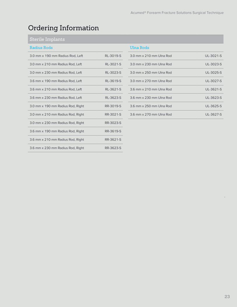
Ordering InformationSterile Implants
Radius Rods Ulna Rods
3.0 mm x 190 mm Radius Rod, Left RL-3019-S 3.0 mm x 210 mm Ulna Rod UL-3021-S
3.0 mm x 210 mm Radius Rod, Left RL-3021-S 3.0 mm x 230 mm Ulna Rod UL-3023-S
3.0 mm x 230 mm Radius Rod, Left RL-3023-S 3.0 mm x 250 mm Ulna Rod UL-3025-S
3.6 mm x 190 mm Radius Rod, Left RL-3619-S 3.0 mm x 270 mm Ulna Rod UL-3027-S
3.6 mm x 210 mm Radius Rod, Left RL-3621-S 3.6 mm x 210 mm Ulna Rod UL-3621-S
3.6 mm x 230 mm Radius Rod, Left RL-3623-S 3.6 mm x 230 mm Ulna Rod UL-3623-S
3.0 mm x 190 mm Radius Rod, Right RR-3019-S 3.6 mm x 250 mm Ulna Rod UL-3625-S
3.0 mm x 210 mm Radius Rod, Right RR-3021-S 3.6 mm x 270 mm Ulna Rod UL-3627-S
3.0 mm x 230 mm Radius Rod, Right RR-3023-S
3.6 mm x 190 mm Radius Rod, Right RR-3619-S
3.6 mm x 210 mm Radius Rod, Right RR-3621-S
3.6 mm x 230 mm Radius Rod, Right RR-3623-S

24
Acumed® Forearm Fracture Solutions Surgical Technique
Ordering Information [continued]
Optional Sterile Implants
Dorsolateral Midshaft Radius Plates Midshaft Volar Radius Plates
14-Hole Midshaft Dorsolateral Radius Plate (180 mm) 70-0466-S 14-Hole Volar Midshaft Radius Plate
(180 mm) 70-0469-S
16-Hole Midshaft Dorsolateral Radius Plate (210 mm) 70-0467-S 16-Hole Volar Midshaft Radius Plate
(210 mm) 70-0470-S
Midshaft Ulna Plates
14-Hole Midshaft Ulna Plate (180 mm) 70-0463-S
16-Hole Midshaft Ulna Plate (210 mm) 70-0464-S
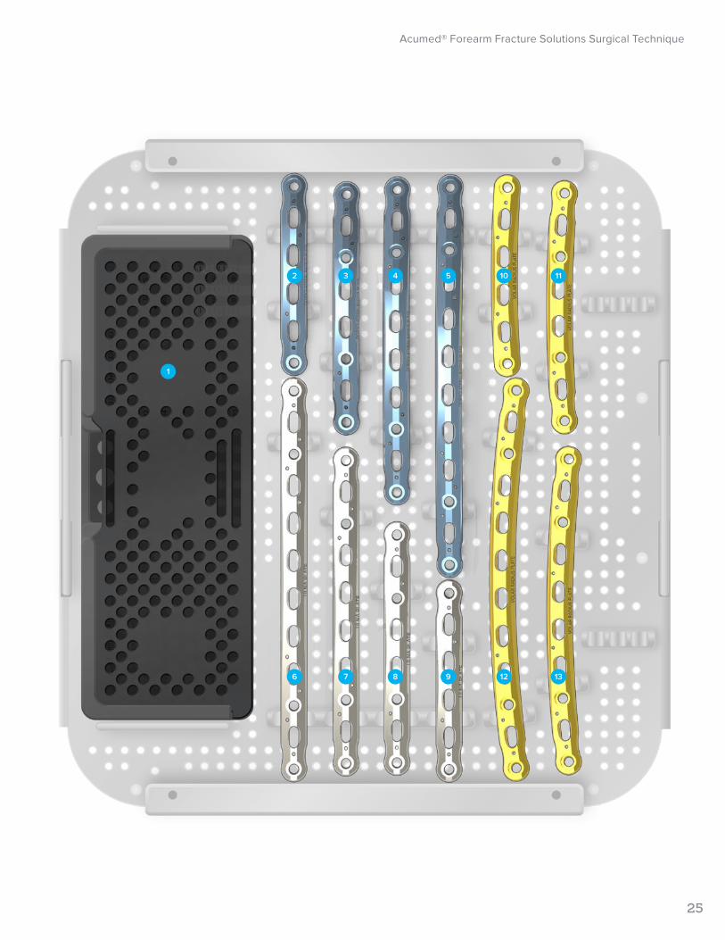
Tray Components
1 Hexalobe Screw Caddy 80-1917 Midshaft Ulna Plates
Dorsolateral Midshaft Radius Plates 6 12-Hole Midshaft Ulna Plate (160 mm) 70-0073
2 6-Hole Dorsolateral Midshaft Radius Plate (80 mm) 70-0074 7 10-Hole Midshaft Ulna Plate (130 mm) 70-0072
3 8-Hole Dorsolateral Midshaft Radius Plate (100 mm) 70-0075 8 8-Hole Midshaft Ulna Plate (100 mm) 70-0071
4 10-Hole Dorsolateral Midshaft Radius Plate (130 mm) 70-0076 9 6-Hole Midshaft Ulna Plate (80 mm) 70-0070
5 12-Hole Dorsolateral Midshaft Radius Plate (160 mm) 70-0077 Midshaft Volar Radius Plates
10 6-Hole Midshaft Volar Radius Plate (80 mm) 70-0066
11 8-Hole Midshaft Volar Radius Plate (100 mm) 70-0067
12 12-Hole MIdshaft Volar Radius Plate (160 mm) 70-0069
13 10-Hole Midshaft Volar Radius Plate (130 mm) 70-0068
Acumed® Forearm Fracture Solutions Surgical Technique
25
2
1
6
3
7
4
8
5
9
10
12
11
13

26
Acumed® Forearm Fracture Solutions Surgical Technique
Ordering Information [continued]
Tray Components
Midshaft Forearm Instrumentation
1 2.3 mm Quick Release Drill 80-0627 11 3.5 mm Cortical Screw Bone Tap MS-LTT35
2 2.8 mm Quick Release Drill 80-0387 12 3.5 mm x 5" Quick Release Drill MS-DC35
3 Periosteal Elevator MS-46212 13 3.0 mm x 5" Quick Release Drill 80-1088
4 Depth Gauge 6–65 mm 80-0623 14 2.8 mm x 5" Quick Release Drill MS-DC28
5 Hexalobe Locking Drill Guide 6–65 mm 80-0668 15 Plate Tack PL-PTACK
6 Large Plate Bender PL-2045 16 T15 Stick Fit Hexalobe Driver 80-0760
7 15 mm Hohmann Retractor MS-46827 17 .045" x 6" ST Guide Wire WS-1106ST
8 2.8 mm/3.5 mm Thin Drill Guide PL-2196 18 .059 x 5" ST Guide Wire WS-1505ST
9 3.5 mm Narrow Drill Guide Cannula PL-2095 19 Plate Clamp 80-0223
10 Medium Ratcheting Driver Handle 80-0663 20 Reduction Forceps with Serrated Jaws PL-CL04
Optional Components
Midshaft Forearm Plate Instrumentation
Angled Drill Guide Assembly 80-0204
Surgical Spreader (Plate Mounted) 80-0251
Surgical Spreader Locking Bolt 80-0252

Acumed® Forearm Fracture Solutions Surgical Technique
27
1
5
2
6
3
7
8
9
10
4
1312
15
14
181716
11
19
20

Plate Clamp 80-0223
Angled Drill Guide Assembly 80-0204
Surgical Spreader (Plate Mounted) 80-0251
Surgical Spreader Locking Bolt 80-0252
28
Acumed® Forearm Fracture Solutions Surgical Technique
Ordering Information [continued]
Tray Components
Forearm Rod Instrumentation
1 Intramedullary Rod Targeting Base MS-0620 10 3.5 mm Targeting Probe HR-3102
2 Intramedullary Rod Locking Bolt MS-0621 11 6.1 mm Cortical Awl Assembly MS-0204
3 Rosette Knob MS-0100 12 2.5 mm Solid Hex Driver Assembly HD-2500
4 Ulna M/L Targeting Guide MS-0622 13 3.5 mm Short Cortical Screw Tap MS-T35S
5 Radius M/L Targeting Guide RA-0622 14 6.1 mm x 5" Drill MS-D761
6 Locking Bolt Finger Wrench MS-0611 15 2.8 mm Tap Drill HR-D105
7 3.5 mm Drill Guide/Depth Gauge HR-3104 16 3.7 mm T-Handle Reamer RMT3730
8 Generic Cannula Assembly MS-2000 17 3.1 mm x 300 mm Intramedullary Rod Reamer RMT3130
9 3.5 mm Targeting Cannula HR-3101

Acumed® Forearm Fracture Solutions Surgical Technique
29
1
5
2
6
3
7
8
9
10
11
4
13
15
14
171612
30
Acumed® Forearm Fracture Solutions Surgical Technique
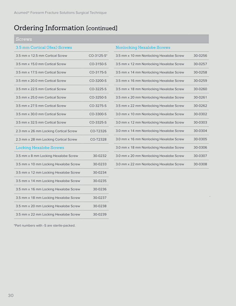
Ordering Information [continued]
Screws
3.5 mm Cortical (Hex) Screws Nonlocking Hexalobe Screws
3.5 mm x 12.5 mm Cortical Screw CO-3125-S* 3.5 mm x 10 mm Nonlocking Hexalobe Screw 30-0256
3.5 mm x 15.0 mm Cortical Screw CO-3150-S 3.5 mm x 12 mm Nonlocking Hexalobe Screw 30-0257
3.5 mm x 17.5 mm Cortical Screw CO-3175-S 3.5 mm x 14 mm Nonlocking Hexalobe Screw 30-0258
3.5 mm x 20.0 mm Cortical Screw CO-3200-S 3.5 mm x 16 mm Nonlocking Hexalobe Screw 30-0259
3.5 mm x 22.5 mm Cortical Screw CO-3225-S 3.5 mm x 18 mm Nonlocking Hexalobe Screw 30-0260
3.5 mm x 25.0 mm Cortical Screw CO-3250-S 3.5 mm x 20 mm Nonlocking Hexalobe Screw 30-0261
3.5 mm x 27.5 mm Cortical Screw CO-3275-S 3.5 mm x 22 mm Nonlocking Hexalobe Screw 30-0262
3.5 mm x 30.0 mm Cortical Screw CO-3300-S 3.0 mm x 10 mm Nonlocking Hexalobe Screw 30-0302
3.5 mm x 32.5 mm Cortical Screw CO-3325-S 3.0 mm x 12 mm Nonlocking Hexalobe Screw 30-0303
2.3 mm x 26 mm Locking Cortical Screw CO-T2326 3.0 mm x 14 mm Nonlocking Hexalobe Screw 30-0304
2.3 mm x 28 mm Locking Cortical Screw CO-T2328 3.0 mm x 16 mm Nonlocking Hexalobe Screw 30-0305
Locking Hexalobe Screws 3.0 mm x 18 mm Nonlocking Hexalobe Screw 30-0306
3.5 mm x 8 mm Locking Hexalobe Screw 30-0232 3.0 mm x 20 mm Nonlocking Hexalobe Screw 30-0307
3.5 mm x 10 mm Locking Hexalobe Screw 30-0233 3.0 mm x 22 mm Nonlocking Hexalobe Screw 30-0308
3.5 mm x 12 mm Locking Hexalobe Screw 30-0234
3.5 mm x 14 mm Locking Hexalobe Screw 30-0235
3.5 mm x 16 mm Locking Hexalobe Screw 30-0236
3.5 mm x 18 mm Locking Hexalobe Screw 30-0237
3.5 mm x 20 mm Locking Hexalobe Screw 30-0238
3.5 mm x 22 mm Locking Hexalobe Screw 30-0239
*Part numbers with -S are sterile-packed.

31
Acumed® Forearm Fracture Solutions Surgical Technique
Notes:

Acumed Headquarters5885 NW Cornelius Pass RoadHillsboro, OR 97124 Office: +1.888.627.9957Office: +1.503.627.9957 Fax: +1.503.520.9618 www.acumed.net
Acumed® is a registered trademark of Acumed LLC
These materials contain information about products that may or may not be available in any particular country or may be available under different trademarks in different countries. The products may be approved or cleared by governmental regulatory organizations for sale or use with different indications or restrictions in different countries. Products may not be approved for use in all countries. Nothing contained on these materials should be construed as a promotion or solicitation for any product or for the use of any product in a particular way which is not authorized under the laws and regulations of the country where the reader is located. Specific questions physicians may have about the availability and use of the products described on these materials should be directed to their particular authorized Acumed distributor. Specific questions patients may have about the use of the products described in these materials or the appropriateness for their own conditions should be directed to their own physician.
ELB10-02-F | Effective: 2017/07 | © 2017 Acumed® LLC