Embed Size (px)
Citation preview
LIT. NO. 13762October 1, 2002
FORD
UNDER-FRAME MOUNT
INSTALLATION INSTRUCTIONS
FOR. .SINGLE-STAGE AND. .TWO~ST AGE TAILGATE SPREADERS
The under-fre mount is recommended tor use on the followig vehicles with an 8 foot box:
1980..1996 Ford F1S0 I F20 I F250 HD I F350.19971'0 HDI.50
This mount is NOT appliable to trucks equipped with a sbort (6-11 foot) box.
Read and understad Installatiøn InstrlJcti()n.~ béfor-iiisfåålittgtbe wwder..fre mounL
TABLE OF CONTENTS
TABLE OF CONTENTS.
SAFTY .......... ,. '. . . . . 1I . .. ... 1Safety Definitions . 0 00 . . ... . . o' 1
Safety Procedures . ~... . . . . . . . .. 1
Battry Safety .... .. . . .. . . . .. 1
WEIGHT RESTRICTONS. . . . . . . . .. 2UNDER-FRAME MOUNTINSTALLATION ........... 3BumperRemovaJ 0......... 3Rear Brackets Installation .'. . . . . . .. 3
Subframe Assembly . .. . . . 0 . . . . . 4
~t1bftåreAssembiylnstailatìon . . . . " 5
Secondary Frae Assembly . . . . . . . . 6
Mounting the Secondary Frame . . 0 . o. 6
Hopper Installation . . . . . . . . . . . . . 7
PARTS LIST . . . . . . . . . . . ~ . . . o. 8Under-Frame Mount Assembly .. . . .. 8
Ford Mounts . . . . . ... . 0 . . . . . . 10
Douglas Dynamcs reeives the right under its product improvement procdures to change constnction or design detals and
fuish equipment when so altered without reference to ilustrations or specifications used herein.
October 1 , 2002 Printed in the U.S.A. Ut. No. 13762
SAFETY
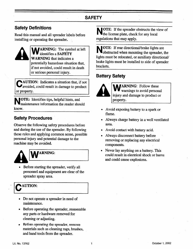
Safety Definitions
Read this manual and all spreader labels beforeinstaling or operatig the spreader.
A.... . W.... ....AR.......... G:. ...TheSymbolatieft
'. .... identifies a SAFETY
W.ARNING that indicates a
potentially hazarous situation that,if not avoided, could result in deathor serious personal injury.
C.' AUTION: Indicates a situation that, if
notavoided, could result in damage to product
or property.
N. ... OTE: Identifies tips, helpful hints, andmaitenance informtion the reader shouldknow.
Safety ProceduresObserve the following safety procedures beforeand during the use of the spreader. By followingthese rules and applying common sense, possiblepersonal injury and potential damage to themachine may be avoided.
A/WARG:. Before stang the spreader, veriy all
personnel and equipment are clea of thespreader spray area.
. I CAU'ON:
· Do not opeate a spreader in nee ofmaintenance.
. Before operatig the spreader, reassemble
any par or hardwar removed for
cieaning or aàjusting.
. R~fote operälìri,g the'spreader,rernove
materials such as cleang rags, brushes,and hand tools from the spreader.
Lit. No. 13762
N.' .... OTE: If
the spreader obstncts the view ofthe license plate, check for any local
regulations that may apply.
NOTE: If rear directionalbrake lights are. . . obstructed when mounting the spreader, thelights must be relocated, or auxiliar directional/
brake lights must be installed to side of spreaderbrackets.
Battery Safety
A WARING: Follow these. ... wargs to avoid penal
.... injur and daage to pruct or
propert .
· Avoid exposing battery to a spark orflame.
· Always charge battery in a wen ventilatedarea.
· Avoid contact with battery acid.
. Always disconnect battery before
removing or replacing any electricaJcomponents.
· Never lay anything on a battery. Thiscould result in electrcal shock or bumsand could cause explosions.
October 1. 2002
WEIGHT RESTRICTIONS
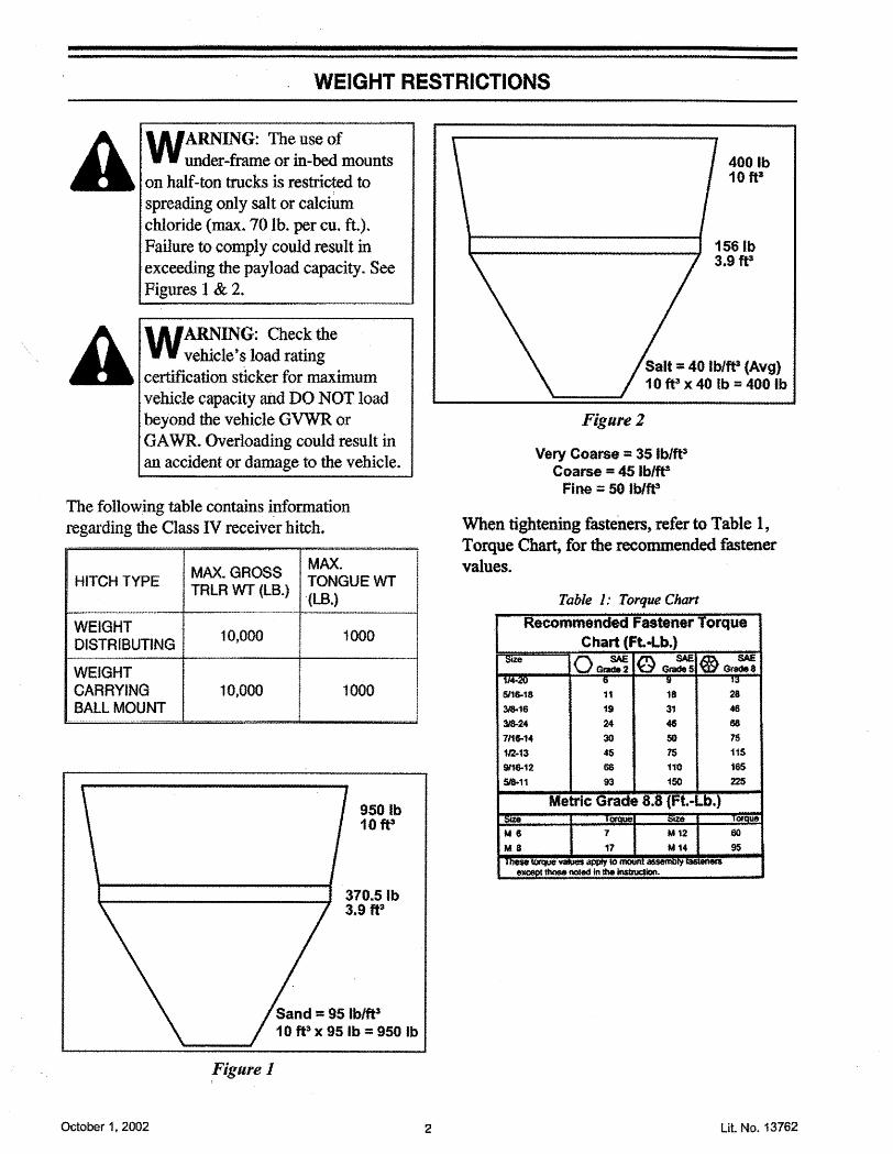
A WARNING: The use of..... ... under-fre or in-bed mounts
.... on half-ton trck is restrct to
spreading only salt or calciumchloride (max. 70 lb. per cu. ft.).Failure to comply could result inexceedng the payload capacity. SeeFigures 1 & 2.
A WARING: Checkthe. ... . . ... vehicle' s loa ra
. . . .. certification sticker for maximumvehicle capacity and DO NOT loadbeyond the vehicleGVW orGA WR. Overloading could result inan accident or damage to the vehicle.
The following table contains ~formationregarding the Class iv receiver hitch.
MAX. GROSS MAX.HITCH TYPE TONGUE WT
TRLR WT (LB.). (LB.)
WEIGHT 10,000 1000DISTRIBUTING
WEIGHTCARRYING 10,000 1000BALL MOUNT
~'.~"'U__'___"_____'''''_'___'
950 Ib1 Oft3
Sand =95 Ib/ft'10 ft3 x 95 Ib = 950 Ib
,Figure 1
October 1. 2002
400 Ib10 ft3
156 Ib3.9 ft'
Salt = 40lblft (Avg)10 ft3 x 40lb = 400 Ib
Figure 2
Very Coarse=35 Iblf'Coarse = 45 Ib/tPFine = 50lblff
When tightening fasteners, refer to Table 1,Torque Char, for the recommended fasteervalues.
5116-18
3&163i24711&44
112-13
916-125111
18
31
46
so75
110
150
11
1$
24
3045
66
93
Metric Grade 8.8 (. t.-Lb.)ue e
2
28
46
68
15
115
165
22
U&
00
95
Lit. No. 13762
UNDER-FRAME MOUNT INSTALLATION
N. ..... OTE: Remove any existing trailer hitch andother after"rrarket equipment which mayinteifere with the installation of this productaccording to these instrctions. '
A WARING: Beforeworking'.. .. ....... .. with th. e spre...a. de.r, seur al
loose fittig clothing and
unrestrained hair.
N. ... OTE: Instal aU fasteners finger tight untilassen1bly is complete. Then tightenaccording to the Torque Char on page 2.
Bumper Removal1. Remove light sockets and bulbs frm bumper.
2. Reïnövetourboltsseuring bumper
mounting brackets to vehicle frame (two boltson each side).
3. Remove bumper and brackets by sliding back.
N. " . OTE: Instal all fasteners finger tight untilassembly is complete. Then tightenaccording to the Torque Chart on page 2.
Rear Brackets Installationi. Loosen bumper mountig brackets at bumper.
See Figure 3.
Figure 3Driver's Sid Shown
Lit. No. 13762
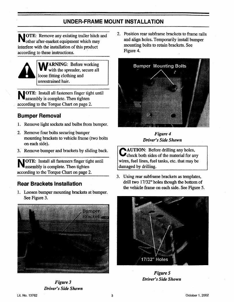
2. Position rear subframe brckets to frame rails
and align holes. Temporarily instal bumpermounting bolts to retan brackets. SeeFigure 4.
:/ligure 4
Drivers Sid Shown
CAUTION: Before drilling
any holes,. .... " 'check: both sides of the material for anywires) fuel lines, fuel t:,etc. that may bedamaged by drilling.
3. Using reasubfre brackets as tennplates,drill two 17/32" holes though the bottom ofthe vehicle frame on each side. See Figure 5.
Figure 5Driver's Sid Shown
3 October 1. 2002
UNDER-FRAME MOUNT INSTALLATION
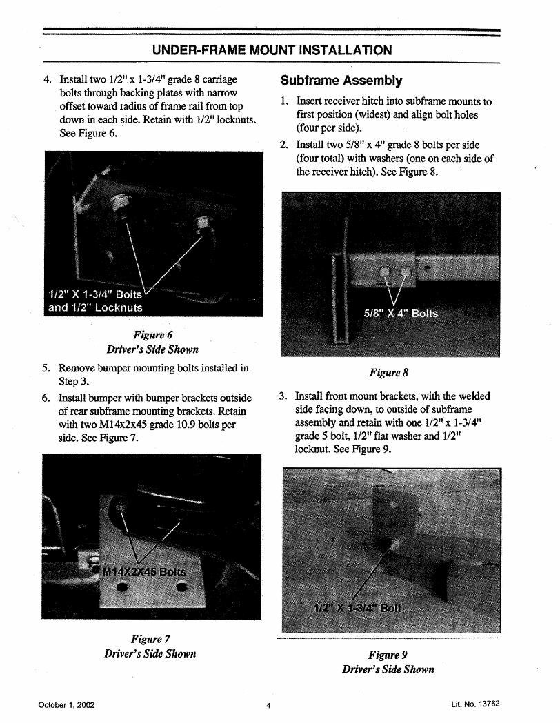
4. In.sta1 two 1/211 x i -3/4" grade 8 carriage
bolts though backing plates with narowoffset toward radius of frame rail from topdown in each side. Reta with 112" locknuts.See Figure 6.
Figure 6Driver's Side Shown
5. Remove bumper mountig bolts instaled inStep 3.
6. Instal bumper with bumper brackets outside
of rea subframe mounting brackets. Retawith two M14x2x45 grde 10.9 bolts perside. See Figure 7.
Figure 7Driver's Side Shown
October 1, 2002
Subframe Assemblyi. Insert receiver hitch into subframe mounts to
first position (widest) and align bolt boles
(four per side).2. Instal two 5/8" x 4JJgrade 8 bolts per side
(four tota) with washers (one on each side of
the receiver hitch). See Figure 8.
Figure 8
3. Instal front mount brackets, with the welded
side facing down, to outside of subframeassembly and reta with one 1/2flx 1-3/4"gradeS bolt, 1/21f flat washer and 1/2"locknut. See Figure 9.
Figure 9Driver's Side Shown
4 Lit. No. 13762
UNDER.FRAME MOUNT INSTALLATION
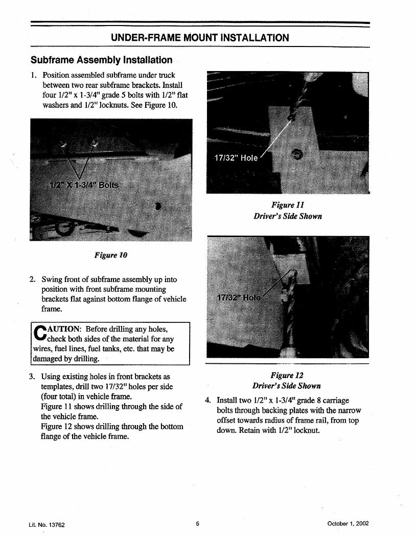
Subframe Assembly Installation1. Position assembled subframe under trck
between two rear subframe brackets. Instalfour 1/2" x 1-3/4u grde 5 bolts with 1/2ll flatwashers and 1/2" locknuts. See Figue i O.
Figure 10
2. Swing front of subfre assembly up into
position with front sub fre mounting
brackets flat agaist bottom flange of vehicleframe.
C. . . .
AUTION: BeforedriUing any holes,check both sides of the material for any
wires, fuel lines, fuel taks,. etc.. that may bed.amaged by drilling.
3. Usingexìsting holes in frontbrackets as
templates, drill two 17/32ll holes per side
(four tota) in vehicle frme..Figure 1 i shows drilling through the side ofthe vehicle fre.
Figure 12 shows drilling through the bottomflange of the vehicle frame..
Lit No. 13762
Fìgure 11
Driver's Side Shown
Figute 12Driver's Side Shown
4. Instal two 1/2" x 1-3/4ft grde 8 caragebolts through backing plate with the narowoffset towards radius of fre raU, from topdown. Retain with 1/2" locknut
5 October 1, 2002

UNDER-FRAME MOUNT INSTAllATION
5. Install two 1/2" x 2" grade 5 bolts and 1/2"
flat washers from inside vehicle fraethough frame and. front brackets. Retain withIJ2u flat washer and 11211 locknut. SeeFigure 13.
. Figure 13Driver's Side Shown
6. Tighten all fasteners according to the Torque
Char on page 2.
7 . Re-instaIlligl1t sockefSa.dbulbs i1 bumper..
Secondary Frame Assembly1. Position center secondar frame setion
betwee curb- and driver-side frame sections.See Under-Frae Mount Assembly drawing
on page 10..
N. .... OTE: Secondar frame must be assembledwith mount bas to the outside of vertcaltubes. Top of center section should beappro~imateiy six inches above top of verticaltubes. The notch in the top cross-member mustface rearard..
NOTE: Center seconda frame may be· assembled th or six inches lower for usewith higher trucks.
October 1, 2002
2. Align holes and instal six 3/8" x 2-1I2l' grade8 bolts through vertical tubes and centersection sideplates. Retan with flat washerand locknuts, three on each side.
3. Tighten all fasteners according to the TorqueChart on page 2.
Moul1tingthe Secondary . Framè1. Position .secol1dååfrál1ebehind trck and
insert mount bars of secondar frame intosubframe pokets. See Figure 14.
Figure 14
2. Slide seondar frme into subframe until3/4" holesaIign.
3. Instal two 3/411 pins through subfre andseconda frme. See Figure 15.
Figure 15
6 Lit No. 13762
UNDER-FRAME MOUNT INSTALLATION
4. Retain 3/4" pins by installing 3/16H linchpin
into hole in 3/4" pins.
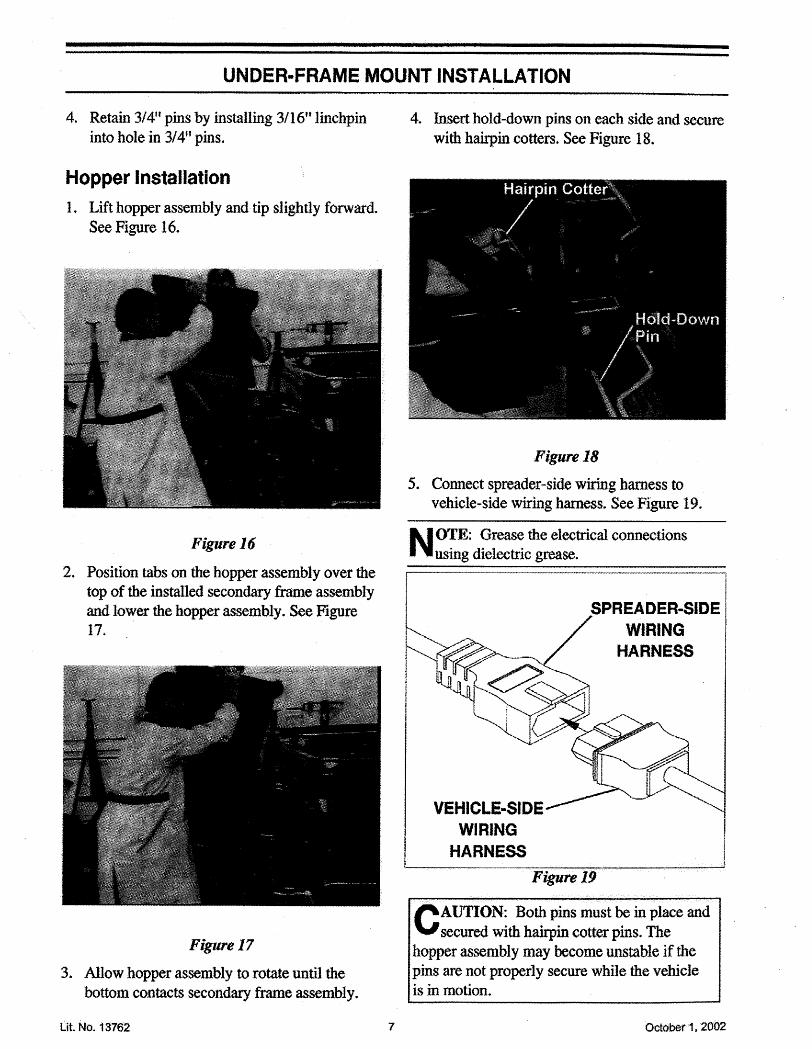
Hopper Installation
i. Lift hoppr assembly and. tip slightly forward.
See Figure 16.
Figure 16
2. Position tabs on the hopper assembly over the
top of the instaled .seonda fre assemblyand lower the hopper asmbly. Se Figure17.
Figure 17
3. Allow hopper assembly to rotate until thebottom contacts secondar frame assembly.
Lit No. 13762
4. Insert hold-down pins on each side and secure
with hairin cottrs. See Figure 18.
Figure 18
5. Connect spreader-side wirng haress to
vehicle-side wiring harss. See Figue 19.
.N. .. .OTE: Greae the electrical connectionsusing dielectric grease.
SPREADER-SIDEWIRING
HARNESS
VEHICLE-SIDEWIRING
HARNESS
Fìgure 19.....
c.... .
AUTION: Both pins must be in place andsecured with haiin cotter pins. The
hopper asmbly may become unstable if thepins are not properly secure while the vehicleis in motion.
7 Octobet 1. 2002
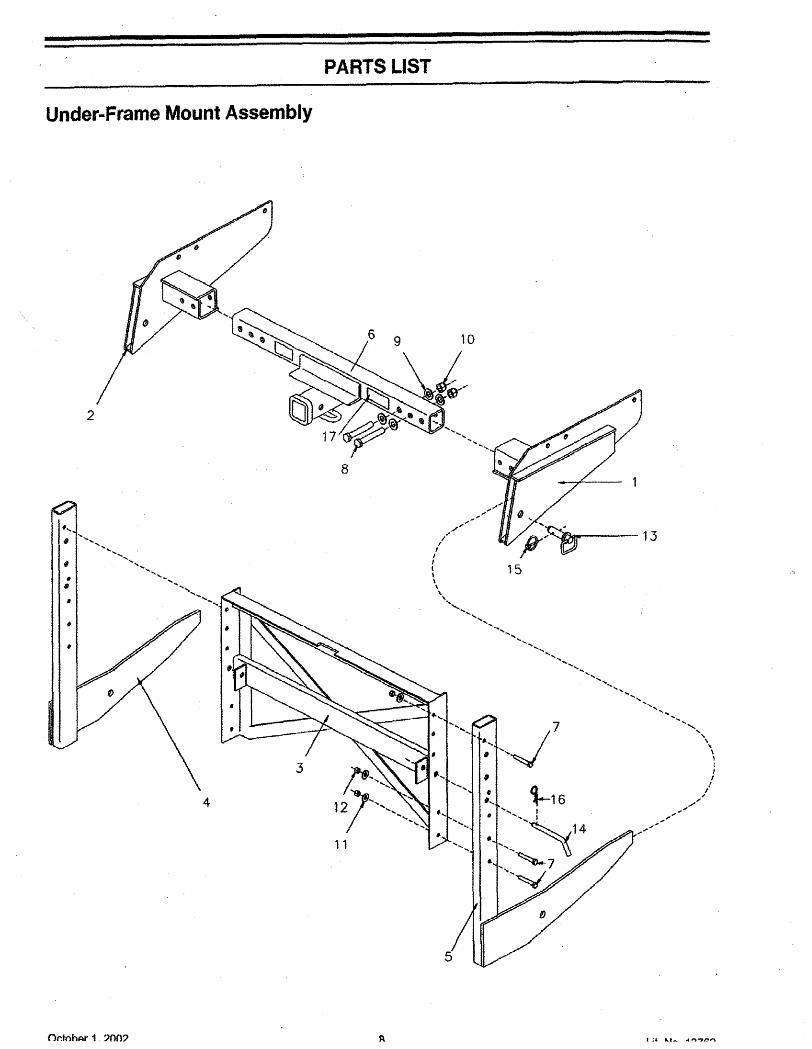
PARTS LIST
Under-Frame Mount Assembly
2
~~~" .7 '..12 . '''''-' "', ......
","';""..
..'"../..I"
I"Ii1L\\\\"',,
...."-'-....
-.'..,....,
.... ....,"
.... .., '..,.., ..,..
......'.. .... ....
..".."\\
;1
Ii...../
",""
..."..,,""
....
13...
...ø ...... .."-,'..',-..-
".... ''''''
....,....
IJ 15".
4
.... 17, ..,~,
.
11 "..
Or:ohAr 1 ?OO? ~ l a;, Lt-. A: ~..~.,

PARTS LIST
Under-Frame Mount Assembly
fiRM QTV.1 i2 i3 14 15 i6 1
7 68 49 810 411 612 613 214 215 216 217 1
DESCRIPTON
?YI0UN SUBFRAME . CUMOUNT SUBFRME - DRSECONDARY FRAME. CTRSECONDARY FRAMESECONDARY FRREt"'lVER HITCH WI LABELS
(includes items 17)
3/8-16X2-1/2 HX CS 08 ZYCSf8-11X4HX CS 08 ZYC5/8 PLAIN WASHER TY A 8AE ZP5/8.11 PT FI LK NUT NYIS ZYC3/8 PLAIN WASHR TY A SID ZP3/8-16 PT me LK NUT NYIS ZYC3/4X2-3/4 HITCH PIN ZYCPIN 1I2''X5.5t13116" LINCHPIN ZYCHAIRIN CO'I 1/8"LABEL - INFORMA110N (WARNIG)
Part 7-16 are found in the followig assembly;i BOLT BAG ASSY
NOTE: See Owner's Manual for repair parnumbers.
Lit. No. 13762
ASSYBPOCBCSCTRcuDR
10!¡HXiLK¡
iNYISInISABSFLSSIDTYZPZYC
ABBREVIATION KEYAsemblyBlack Phosphat a.nd OilCarage BoltCap ScrewCenterCurb-SideDriver-Side'GradeHexLokNylon hhsertPrevailing TorqueSocety of Automotive Engineers
Serrated Flange Lock ScrewStandardTypeZic PläteZinc Yenow Chomate
9 October 1. 2002
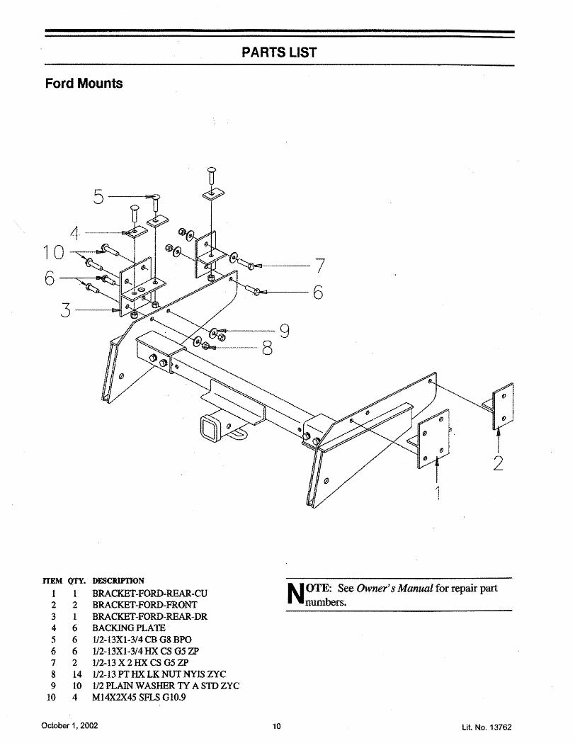
PARTS LIST
Ford Mounts
---.----.~- 7
6
9
ITEM QTY. DECIUONi 1 BRACKET-FORD-REA-CU2 2 BRACKET-FORDFRONT3 1 BRACKET-PORD-REAR-DR4 6 BACKING PLATE5 6 1/2-13Xl-3/4CB 08 BPO6 6 1/2-13Xl-3/4HXCSG5ZP7 2 1/2-13X2HX CS 05 ZP8 14 1/2-13 PT HX LK NU NYIS ZYC9 10 1/2PLAIN.WASHER IT ASTDZYC10 4 M14X2X45 SFLS G10.9
N.. OTE: See Owner's Manual for repair parnumbers.
October 1, 2002 10 Lit No. 13762


