Embed Size (px)
Citation preview
INSTALLATIONINSTRUCTIONS
9002-2750v2 Instructions 6-28-17.docx Page 1 of 6 GS
Ford 4” MyFord factory display interface for backup camera (Kit # 9002-2750v2)
Please read thoroughly before starting installation and check that kit contents are complete.
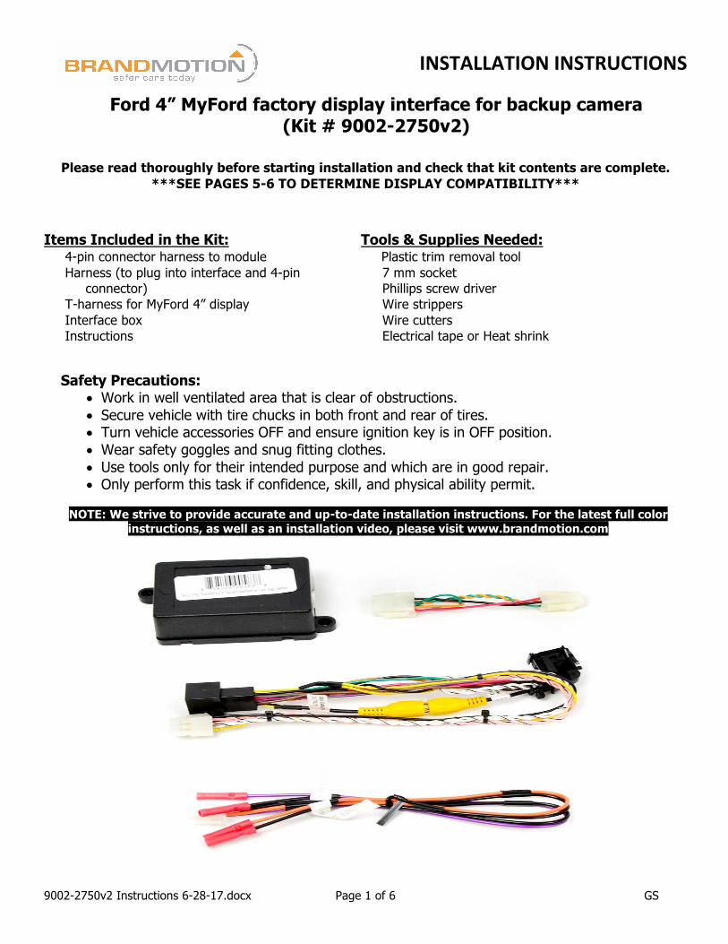
***SEE PAGES 5-6 TO DETERMINE DISPLAY COMPATIBILITY*** Items Included in the Kit: Tools & Supplies Needed:
4-pin connector harness to module Harness (to plug into interface and 4-pin
connector) T-harness for MyFord 4” display Interface box Instructions
Plastic trim removal tool 7 mm socket Phillips screw driver Wire strippers Wire cutters Electrical tape or Heat shrink
Safety Precautions:
• Work in well ventilated area that is clear of obstructions. • Secure vehicle with tire chucks in both front and rear of tires. • Turn vehicle accessories OFF and ensure ignition key is in OFF position. • Wear safety goggles and snug fitting clothes. • Use tools only for their intended purpose and which are in good repair. • Only perform this task if confidence, skill, and physical ability permit.
NOTE: We strive to provide accurate and up-to-date installation instructions. For the latest full color
instructions, as well as an installation video, please visit www.brandmotion.com
INSTALLATIONINSTRUCTIONS
9002-2750v2 Instructions 6-28-17.docx Page 2 of 6 GS
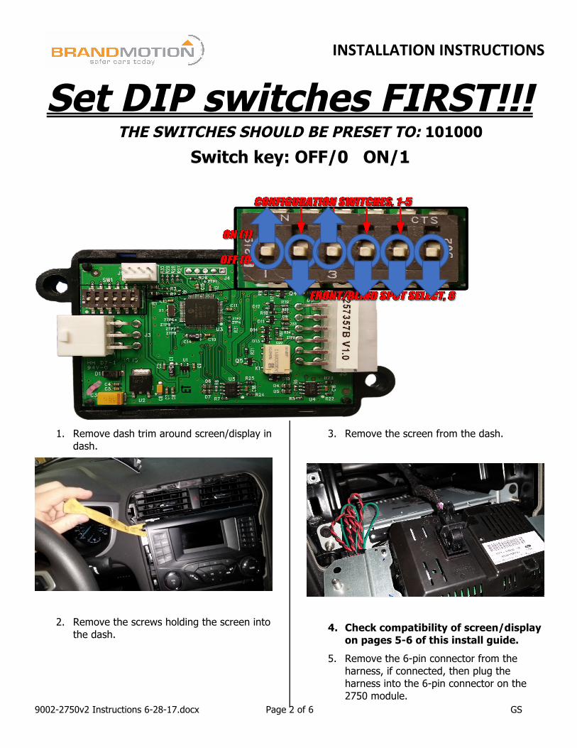
Set DIP switches FIRST!!! THE SWITCHES SHOULD BE PRESET TO: 101000
Switch key: OFF/0 ON/1
1. Remove dash trim around screen/display in dash.
2. Remove the screws holding the screen into the dash.
3. Remove the screen from the dash.
4. Check compatibility of screen/display on pages 5-6 of this install guide.
5. Remove the 6-pin connector from the harness, if connected, then plug the harness into the 6-pin connector on the 2750 module.
INSTALLATIONINSTRUCTIONS
9002-2750v2 Instructions 6-28-17.docx Page 3 of 6 GS
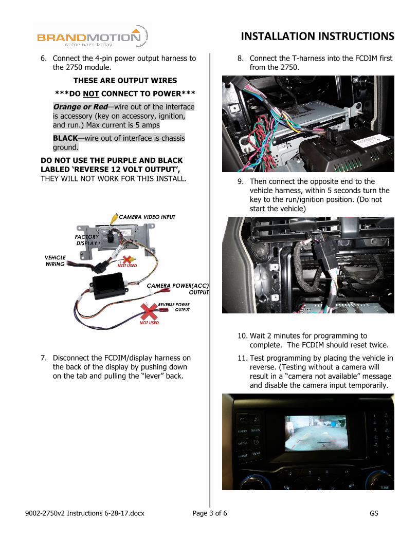
6. Connect the 4-pin power output harness to the 2750 module.
THESE ARE OUTPUT WIRES ***DO NOT CONNECT TO POWER*** Orange or Red—wire out of the interface is accessory (key on accessory, ignition, and run.) Max current is 5 amps BLACK—wire out of interface is chassis ground.
DO NOT USE THE PURPLE AND BLACK LABLED ‘REVERSE 12 VOLT OUTPUT’, THEY WILL NOT WORK FOR THIS INSTALL.
7. Disconnect the FCDIM/display harness on the back of the display by pushing down on the tab and pulling the “lever” back.
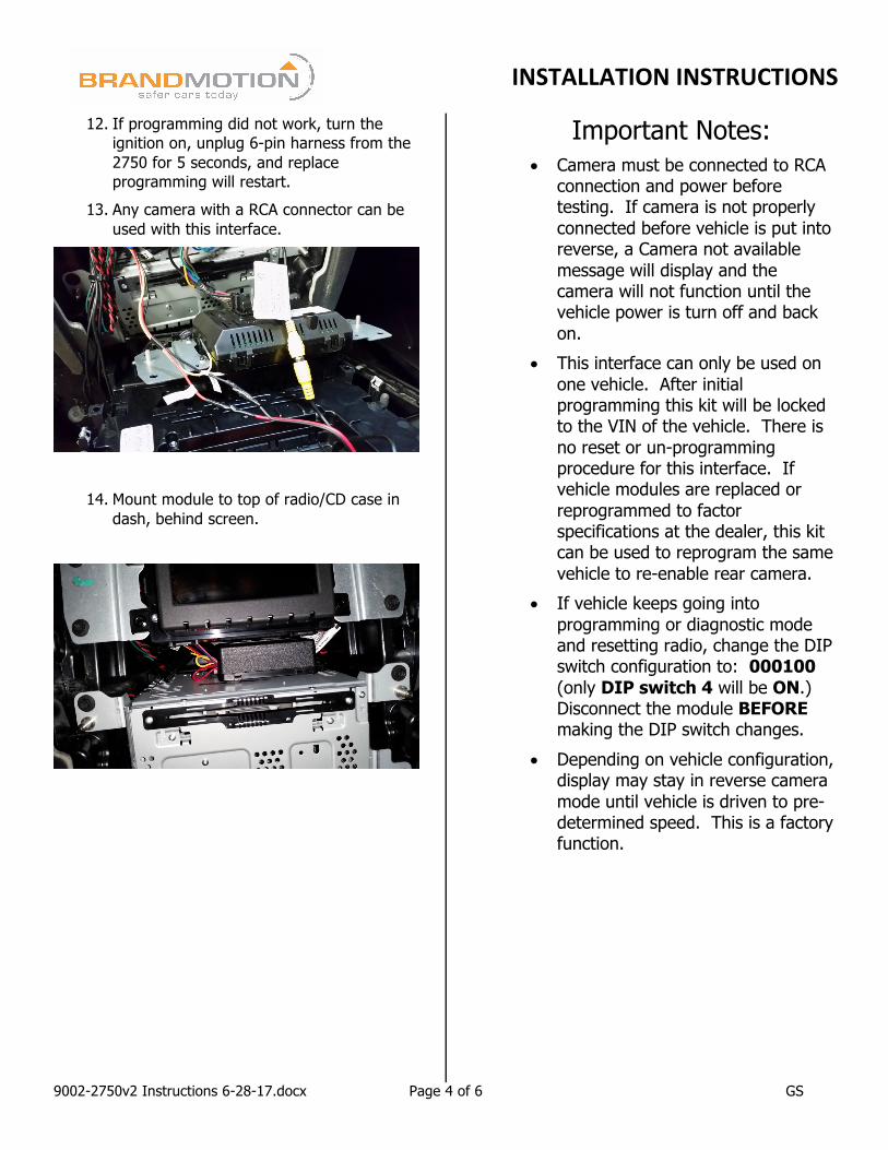
8. Connect the T-harness into the FCDIM first from the 2750.
9. Then connect the opposite end to the
vehicle harness, within 5 seconds turn the key to the run/ignition position. (Do not start the vehicle)
10. Wait 2 minutes for programming to complete. The FCDIM should reset twice.
11. Test programming by placing the vehicle in reverse. (Testing without a camera will result in a “camera not available” message and disable the camera input temporarily.
INSTALLATIONINSTRUCTIONS
9002-2750v2 Instructions 6-28-17.docx Page 4 of 6 GS
12. If programming did not work, turn the ignition on, unplug 6-pin harness from the 2750 for 5 seconds, and replace programming will restart.
13. Any camera with a RCA connector can be used with this interface.
14. Mount module to top of radio/CD case in dash, behind screen.
Important Notes: • Camera must be connected to RCA
connection and power before testing. If camera is not properly connected before vehicle is put into reverse, a Camera not available message will display and the camera will not function until the vehicle power is turn off and back on.
• This interface can only be used on one vehicle. After initial programming this kit will be locked to the VIN of the vehicle. There is no reset or un-programming procedure for this interface. If vehicle modules are replaced or reprogrammed to factor specifications at the dealer, this kit can be used to reprogram the same vehicle to re-enable rear camera.
• If vehicle keeps going into programming or diagnostic mode and resetting radio, change the DIP switch configuration to: 000100 (only DIP switch 4 will be ON.) Disconnect the module BEFORE making the DIP switch changes.
• Depending on vehicle configuration, display may stay in reverse camera mode until vehicle is driven to pre-determined speed. This is a factory function.
INSTALLATIONINSTRUCTIONS
9002-2750v2 Instructions 6-28-17.docx Page 5 of 6 GS
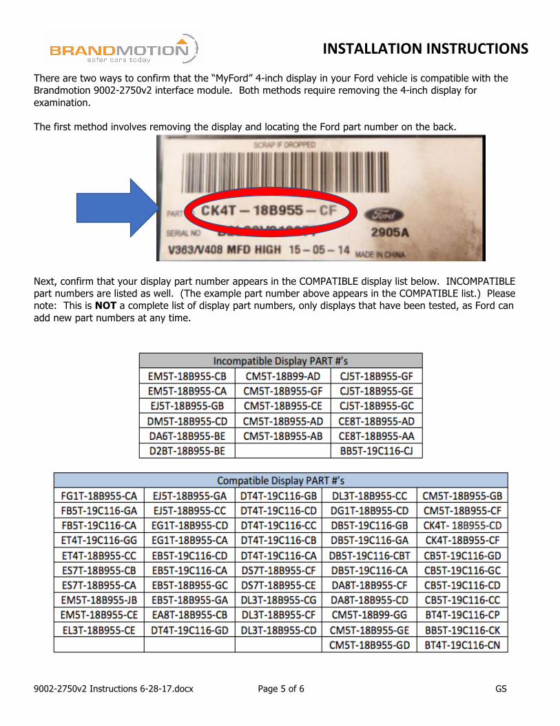
There are two ways to confirm that the “MyFord” 4-inch display in your Ford vehicle is compatible with the Brandmotion 9002-2750v2 interface module. Both methods require removing the 4-inch display for examination. The first method involves removing the display and locating the Ford part number on the back.
Next, confirm that your display part number appears in the COMPATIBLE display list below. INCOMPATIBLE part numbers are listed as well. (The example part number above appears in the COMPATIBLE list.) Please note: This is NOT a complete list of display part numbers, only displays that have been tested, as Ford can add new part numbers at any time.
INSTALLATIONINSTRUCTIONS
9002-2750v2 Instructions 6-28-17.docx Page 6 of 6 GS
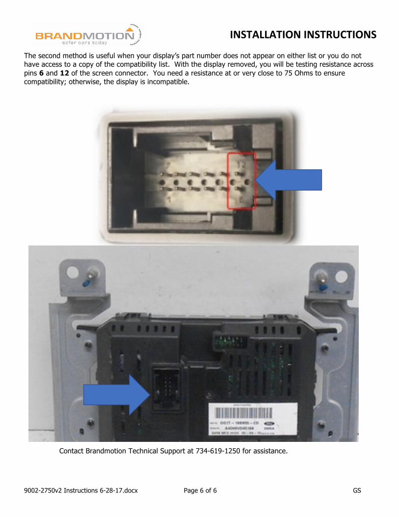
The second method is useful when your display’s part number does not appear on either list or you do not have access to a copy of the compatibility list. With the display removed, you will be testing resistance across pins 6 and 12 of the screen connector. You need a resistance at or very close to 75 Ohms to ensure compatibility; otherwise, the display is incompatible.
Contact Brandmotion Technical Support at 734-619-1250 for assistance.