Embed Size (px)
Citation preview
Copyright © 2006, TRINAMIC Motion Control GmbH & Co. KG www.trinamic.com
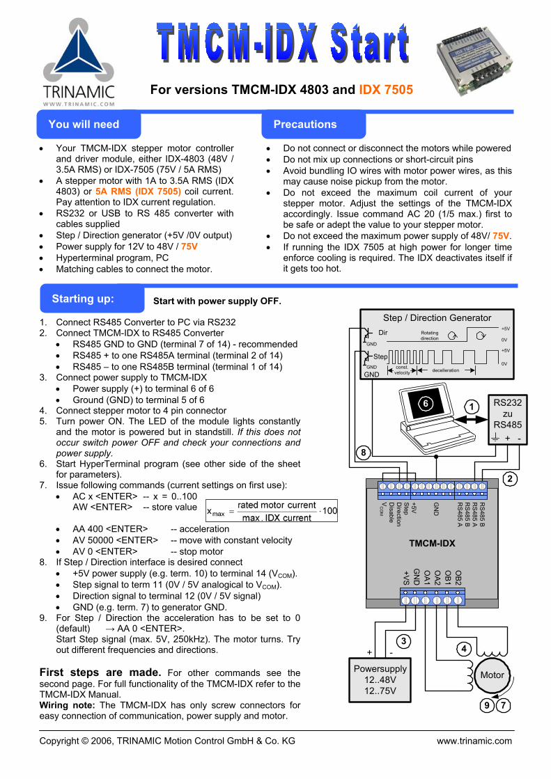
For versions TMCM-IDX 4803 and IDX 7505
• Your TMCM-IDX stepper motor controller and driver module, either IDX-4803 (48V / 3.5A RMS) or IDX-7505 (75V / 5A RMS)
• A stepper motor with 1A to 3.5A RMS (IDX 4803) or 5A RMS (IDX 7505) coil current. Pay attention to IDX current regulation.
• RS232 or USB to RS 485 converter with cables supplied
• Step / Direction generator (+5V /0V output) • Power supply for 12V to 48V / 75V • Hyperterminal program, PC • Matching cables to connect the motor.
• Do not connect or disconnect the motors while powered • Do not mix up connections or short-circuit pins • Avoid bundling IO wires with motor power wires, as this
may cause noise pickup from the motor. • Do not exceed the maximum coil current of your
stepper motor. Adjust the settings of the TMCM-IDX accordingly. Issue command AC 20 (1/5 max.) first to be safe or adept the value to your stepper motor.
• Do not exceed the maximum power supply of 48V/ 75V. • If running the IDX 7505 at high power for longer time
enforce cooling is required. The IDX deactivates itself if it gets too hot.
Start with power supply OFF.
1. Connect RS485 Converter to PC via RS232 2. Connect TMCM-IDX to RS485 Converter
• RS485 GND to GND (terminal 7 of 14) - recommended • RS485 + to one RS485A terminal (terminal 2 of 14) • RS485 – to one RS485B terminal (terminal 1 of 14)
3. Connect power supply to TMCM-IDX • Power supply (+) to terminal 6 of 6 • Ground (GND) to terminal 5 of 6
4. Connect stepper motor to 4 pin connector 5. Turn power ON. The LED of the module lights constantly
and the motor is powered but in standstill. If this does not occur switch power OFF and check your connections and power supply.
6. Start HyperTerminal program (see other side of the sheet for parameters).
7. Issue following commands (current settings on first use): • AC x <ENTER> -- x = 0..100
AW <ENTER> -- store value
• AA 400 <ENTER> -- acceleration • AV 50000 <ENTER> -- move with constant velocity • AV 0 <ENTER> -- stop motor
8. If Step / Direction interface is desired connect • +5V power supply (e.g. term. 10) to terminal 14 (VCOM). • Step signal to term 11 (0V / 5V analogical to VCOM). • Direction signal to terminal 12 (0V / 5V signal) • GND (e.g. term. 7) to generator GND.
9. For Step / Direction the acceleration has to be set to 0 (default) → AA 0 <ENTER>. Start Step signal (max. 5V, 250kHz). The motor turns. Try out different frequencies and directions.
First steps are made. For other commands see the second page. For full functionality of the TMCM-IDX refer to the TMCM-IDX Manual. Wiring note: The TMCM-IDX has only screw connectors for easy connection of communication, power supply and motor.
GND
GND
Step0V
const.velocity
Dir+5V
0VRotatingdirection
decelleration
+5V
Step / Direction Generator
GND
Powersupply12..48V12..75V
Motor
-+
2
3
8
4
79
6
TMCM-IDX
RS
485 BR
S485 A
RS
485 BR
S485 A
GN
D
+5VS
tepD
irectionD
isableV
CO
M
OB2
OB1
OA2
OA1
GN
D+VS
1 RS232zu
RS485+ -
Starting up:
You will need Precautions
Copyright © 2006, TRINAMIC Motion Control GmbH & Co. KG www.trinamic.com
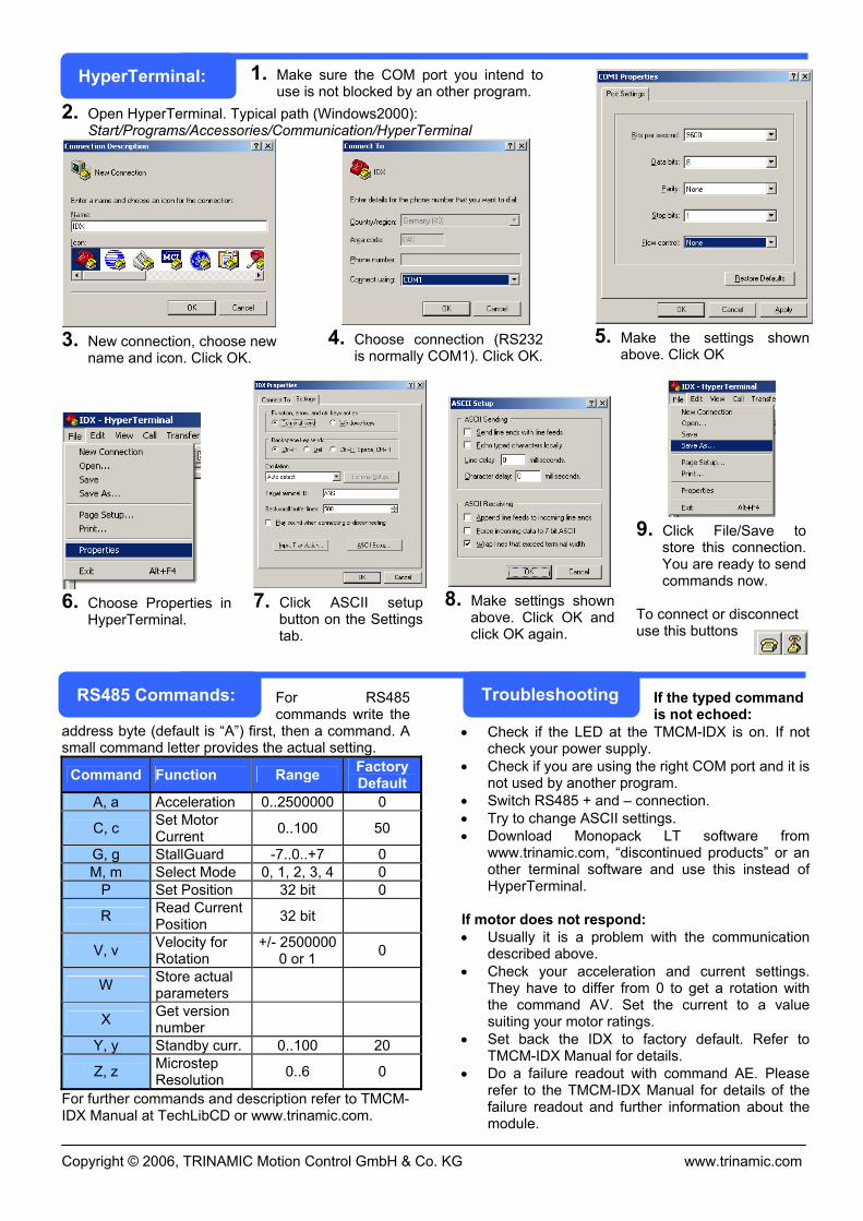
1. Make sure the COM port you intend to use is not blocked by an other program.
2. Open HyperTerminal. Typical path (Windows2000): Start/Programs/Accessories/Communication/HyperTerminal
3. New connection, choose new
name and icon. Click OK.
4. Choose connection (RS232
is normally COM1). Click OK. 5. Make the settings shown
above. Click OK
6. Choose Properties in
HyperTerminal.
7. Click ASCII setup
button on the Settings tab.
8. Make settings shown
above. Click OK and click OK again.
9. Click File/Save to
store this connection. You are ready to send commands now.
To connect or disconnect use this buttons
For RS485 commands write the
address byte (default is “A”) first, then a command. A small command letter provides the actual setting.
Command Function Range Factory Default
A, a Acceleration 0..2500000 0
C, c Set Motor Current 0..100 50
G, g StallGuard -7..0..+7 0 M, m Select Mode 0, 1, 2, 3, 4 0
P Set Position 32 bit 0
R Read Current Position 32 bit
V, v Velocity for Rotation
+/- 2500000 0 or 1 0
W Store actual parameters
X Get version number
Y, y Standby curr. 0..100 20
Z, z Microstep Resolution 0..6 0
For further commands and description refer to TMCM-IDX Manual at TechLibCD or www.trinamic.com.
If the typed command is not echoed:
• Check if the LED at the TMCM-IDX is on. If not check your power supply.
• Check if you are using the right COM port and it is not used by another program.
• Switch RS485 + and – connection. • Try to change ASCII settings. • Download Monopack LT software from
www.trinamic.com, “discontinued products” or an other terminal software and use this instead of HyperTerminal.
If motor does not respond: • Usually it is a problem with the communication
described above. • Check your acceleration and current settings.
They have to differ from 0 to get a rotation with the command AV. Set the current to a value suiting your motor ratings.
• Set back the IDX to factory default. Refer to TMCM-IDX Manual for details.
• Do a failure readout with command AE. Please refer to the TMCM-IDX Manual for details of the failure readout and further information about the module.
HyperTerminal:
RS485 Commands: Troubleshooting