Embed Size (px)
Citation preview
M2015 – Effective October 1, 2014, Page 1 of 44
2015 STANDARD FOR PROTECTIVE HEADGEAR
For Use with Motorcycles and Other Motorized Vehicles
Special Note to Helmet Users
There are four reasons for you to be interested in this Standard:
1. The use of motorcycles and other motorized vehicles imposes risks of death or
permanent impairment due to head injury.
2. The proper use of protective helmets can minimize the risk of death or
permanent impairment.
3. The protective capacity of a helmet is difficult to estimate, particularly at the
time of purchase or use. Protective capability is currently measured by
destructive testing which is beyond the means of most helmet wearers.
4. Snell certification backed by ongoing destructive testing samples taken
randomly from dealers and distributors identifies those helmet models providing
and maintaining the highest levels of head protection.
Four of the most critical elements affecting a helmet's protective properties are:
1. Impact management - how well the helmet protects against collisions with large
objects.
2. Helmet positional stability - whether the helmet will be in place, on the head,
when it's needed.
3. Retention system strength - whether the chin straps are sufficiently strong to
hold the helmet throughout a head impact.
4. Extent of Protection - the area of the head protected by the helmet.
M2015 – Effective October 1, 2014, Page 2 of 44
This Standard describes simple tests for all four of these items. However, the
tests for the second item, helmet stability, of necessity presume that the helmet is well
matched to the wearer's head and that it has been carefully adjusted to obtain the
best fit possible. Unless you take similar care in the selection and fitting of your own
helmet, you may not obtain the level of protection that current headgear can provide.
The Foundation recommends the simple, straightforward procedure
recommended to consumers by most helmet manufacturers:
Position the helmet on your head so that it sits low on your forehead; if you
can't see the edge of the brim at the extreme upper range of your vision, the helmet is
probably out of place. Adjust the retention system so that when in use, it will hold the
helmet firmly in place. This positioning and adjusting should be repeated to obtain the
very best result possible. The procedure initially may be time consuming. Take the
time.
Try to remove the helmet without undoing the retention system closures. If the
helmet comes off or shifts over your eyes, readjust and try again. If no adjustment
seems to work, this helmet is not for you; try another.
This procedure is also the basis of the test for helmet stability described in this
Standard. This test performs the same steps but uses standard head forms.
However, you must still perform this procedure for yourself when buying a helmet and
every time you wear a helmet. Only in this way will you be able to make all the proper
adjustments to get the best fit possible. Furthermore, your test on your own head will
be an improvement on ours; you will determine whether the helmet is appropriate for
you personally.
M2015 – Effective October 1, 2014, Page 3 of 44
There are several other important aspects of helmets to consider. Full face
helmets provide a measure of protection from facial injuries. These helmets
incorporate a rigid "chin" guard which covers the lower part of the face. The
Foundation has devised special tests for the chin bars of full face helmets.
There are two varieties of full face helmets. The chin guard may be an integral,
immovable part of the helmet but, in so-called “modular” or “flip-up” helmets the chin
guard may be hinged so that, when released, it will pivot or flip up and out of the way
for the rider’s convenience. Modular helmets must meet all the same requirements as
those equipped with integral chin bars with the additional requirement that the chin
guard release mechanism must be sufficiently secure to prevent inadvertent opening
in a crash impact.
Some helmets come with a separate structure which bolts to the helmet and
which is intended to cover the lower part of the face. These removable chin bars are
often intended to deflect small stones and debris encountered in some motorcycle
sports and may not be effective facial protection in falls and accidents. The
Foundation does not test bolt-on chin bars and considers any headgear equipped with
them to be an open face helmet.
If a full face helmet is equipped with a face shield, it may also provide a
measure of eye protection. The Foundation tests the face shields of full face helmets
for particle penetration resistance. Face shields provided with open face helmets
generally do not provide the same levels of eye protection and, for that reason are not
considered.
M2015 – Effective October 1, 2014, Page 4 of 44
The shells of both open and full face helmets should also provide a measure of
protection from penetration. The Foundation tests the shells of both full and open
face helmets for penetration resistance.
Effective headgear must be removable. Paramedics and other emergency
personnel must be able to quickly remove headgear from accident victims in order to
check for vital signs and to perform emergency procedures. The Foundation has
devised tests and criteria for helmet removability.
The Foundation tests helmets for visual field. The helmet must provide a
minimum range of vision appropriate to its use as measured on standard head forms.
Most Snell certified helmets will meet the requirements stated in this Standard and are
considered appropriate for street use. However, the Foundation may also certify
headgear with much more restricted visual fields for use only in carefully controlled
competitive environments. Such headgear will include warning labels identifying them
as appropriate only for certain activities.
Be absolutely certain that your helmet is appropriate for your intended uses.
Furthermore, since the range of vision you obtain may vary considerably from our
measurement, be absolutely certain that the helmet and face shield permit you
adequate vision.
There are several important factors which the Foundation does not consider
directly but which bear on the effectiveness of protective helmets. Be certain your
helmet is wearable, that is, that it’s comfortable and adequately ventilated when worn
for prolonged periods. Few people will wear an uncomfortable helmet. A helmet that
is not worn won't protect anyone. Also, while you’re trying the helmet on, take a good
M2015 – Effective October 1, 2014, Page 5 of 44
look in a mirror and ask some friends what they think. Most people will quit using an
ugly helmet much more quickly than one that is merely uncomfortable.
Check for conspicuity. Bright colors and reflective patches will make you more
visible to others and therefore less likely to be involved in a collision. All your riding
gear and especially your helmet should be unmistakable, even to the most inattentive
driver.
FOREWORD
In a motorcycle accident, the rider may suffer injury or death. Helmets on the
market today offer varying degrees of protection, but the consumer has little basis for
judging the relative effectiveness of a given model. This Standard presents rational
methods for identifying those helmet models which definitely meet specified standards
for impact (crash) protection and retention system strength and, afterwards, identifying
those which definitely have ceased to meet those standards.
The Snell Foundation urges that protective helmets be required for all
individuals participating in supervised racing events and encourages the general
public to wear helmets which meet appropriate performance standards1.
This 2015 Standard establishes performance characteristics suitable for
motorcycling and for use with other open motorized vehicles in which the driver and
passengers may not be enclosed such as boats, motorized carts, all-terrain vehicles
and snowmobiles. This Standard does not establish construction and material
1The Foundation has also published Standards for headgear used in bicycling, non-motorized sports, automobile racing, karting, competitive skiing, skiing and snowboarding and equestrian activities. Copies of these Standards are available upon request.
M2015 – Effective October 1, 2014, Page 6 of 44
specifications. The Foundation does not recommend specific materials or
designs. Manufacturers voluntarily submit helmets to be tested to this Standard and
if the submitted helmets pass, a certification is issued.
The Foundation will make available the identity of those products which have
been Snell certified but will not attempt to rank those products according to
performance nor to any other criteria. Neither does the Foundation distinguish
between the needs of participants in competitive events and those of the general
public.
All of the requirements described herein, including both initial
certification and random sample testing, are an integral part of this Standard.
No helmet can satisfy the Standard unless it is subject to both certification and
random sample testing by the Foundation.
Snell certification for protective headgear requires a specific contractual
agreement between the primary headgear manufacturer and the Foundation.
Certification procedures may be obtained upon application to the Foundation.
SNELL MEMORIAL FOUNDATION is a registered certification mark and
M2015 is a certification mark of the Snell Memorial Foundation.
INTRODUCTION
This Standard addresses the problem of protecting the head from direct impact
with surfaces or objects that might be encountered in a motorcycling accident. The
Standard prescribes direct measures of several factors bearing on a helmet's ability to
protect the head as well as its general serviceability as motorcyclist headgear. Thus,
this Standard is directed towards the kinds of performance bearing on head protection

M2015 – Effective October 1, 2014, Page 7 of 44
that may not readily be discernable by even knowledgeable consumers at the time of
purchase.
Some of these performance requirements have been expressed in terms of
limitations on the various components and features of the single general helmet
configuration currently available. These expressions have been used only for the
sake of clarity and should not be misinterpreted as requiring specific configurations or
materials. As newer helmet technologies appear, these limitations will be re-examined
and, perhaps, restated.
A motorcycle helmet consists generally of a rigid head covering and a retention
system composed of flexible straps and hardware. The rigid covering consists of a
strong, stiff outer shell and a crushable liner. The stiff outer shell protects by its
capacity to spread a concentrated load at its outer surface over a larger area of the
liner and the wearer's head. The crushable liner protects the head from direct impact
by its capacity to manage impact energy. Since there is no certain way to anticipate
the severity of a head impact or whether the impact surface will be such that it will
spread the load over the helmet or concentrate it at a single point, the most generally
effective helmet will combine the strongest, stiffest possible outer shell with a liner
chosen to limit the peak deceleration of the wearer’s head to within tolerable limits.
The retention system holds the headgear in position throughout normal usage
and especially during falls and accidents, ensuring that the helmet will be in place to
manage a direct impact. This Standard applies two different tests to the retention
system. The first of these tests for stability by fitting the headgear to a standard head
form and then attempting to displace it by applying tangential shock loadings. The
M2015 – Effective October 1, 2014, Page 8 of 44
second tests retention system strength by applying a shock load to the system
components through a simulated chin.
The quality of the fit and the care taken with the adjustments are absolutely
critical elements in these tests. The manufacturer must provide suitable guidance
so that the wearer will be able to select and adjust headgear to obtain the
necessary quality of fit and positional stability.
The capacity for impact protection is determined by direct measurement of the
shock delivered through the helmet to a head form when the helmeted head form is
dropped in a specified manner onto any of three unyielding anvils.
Most motorcycle helmets are intended to accommodate a range of head sizes
and shapes. Various thicknesses of resilient padding are sometimes placed within
otherwise identical helmets during production or during fitting to configure the helmet
to several different ranges of head size. This resilient padding does not significantly
affect the way the helmet absorbs and attenuates impact and is not directly addressed
in this Standard.
The helmet must also resist penetration by sharp edged and pointed
projections and projectiles. This capacity is tested by placing the helmet on a head
form and dropping a metal cone of specified mass and geometry onto the shell. The
tip of this cone must not penetrate to the head form.
Similarly, the helmets must resist chemical attack by bodily fluids as well as
solvents and chemicals associated with motorsports. This capacity may be tested by
applying a solvent mix before further conditioning and testing.
M2015 – Effective October 1, 2014, Page 9 of 44
Full face helmets including “modular” or “flip-up” helmets provide a measure of
facial protection in addition to the impact protection generally sought. The principle
feature of these is a chin bar that extends forward to cover the jaw area converting the
facial opening into a visual port. Frequently, a face shield is also provided so that the
wearer's face is completely covered.
In traditional full face helmets, the chin bar is an integral, immovable part of the
helmet structure. In “modular” or “flip-up” full face configurations, the chin bar may be
released to pivot about a hinge up and away from the face enabling wearers to adjust
eyeglasses, eat, drink or converse when not actually riding. Although other helmets
may be configured to allow the use of “bolt-on” chin bar elements, these helmets are
not considered to be full face and are treated instead as open face configurations.
For full face helmets, this Standard tests the rigidity of the chin bar by dropping
a weight onto it at a specified velocity so as to attempt to force the chin bar toward the
interior of the helmet. The chin bar must not deflect more than a specified amount.
If a face shield is provided with a full face helmet, then this face shield must
resist penetration by small particles. A sharp lead pellet of a specified weight is
directed into the face shield at a specified velocity. The pellet must not penetrate into
the helmet interior.
This Standard also includes a test intended to determine whether the headgear
may be removed from an unconscious accident victim quickly, easily and reliably in
spite of any damage the headgear might reasonably be expected to sustain.
Traditional helmet architectures have satisfied this requirement so readily that many
Standards including previous Snell Foundation Standards have not mentioned it.
M2015 – Effective October 1, 2014, Page 10 of 44
Even so, it is unthinkable that a headgear might protect its wearer in an accident only
to thwart attempts at rescue afterward.
Inadequate ventilation may render a helmet unwearable in hot climates,
especially if the helmet is full faced. But this Standard makes no direct demands on
either the quantity or quality of air flow to the wearer.
Other general features of motorcycle helmets may include eyeshades and
accommodations for goggles, and visibility enhancements such as bright colors and
reflective surfaces. These features all deal with matters of safety and comfort that are
not directly addressed in this Standard but which merit the consideration of wearers as
well as manufacturers.
Although helmet use has been shown to reduce the risk of head injuries
significantly, there are limits to a helmet's protective capability. No helmet can protect
the wearer against all foreseeable accidents. Therefore injury may occur in accidents
which exceed the protective capability of any helmet including even those helmets
meeting the requirements of this Standard.
A helmet's protective capability may be exhausted protecting the wearer in an
accident. Helmets are constructed so that the energy of a blow is managed by the
helmet, causing its partial destruction. The damage may not be readily apparent and
the Foundation strongly recommends that a helmet involved in an accident be
returned to the manufacturer for complete inspection. If it is not possible to do so, the
helmet should always be destroyed and replaced.
Finally, the protective capability may diminish over time. Some helmets are
made of materials which deteriorate with age and therefore have a limited life span.

M2015 – Effective October 1, 2014, Page 11 of 44
At the present time, the Foundation recommends that motorcycle helmets be replaced
after five (5) years, or less if the manufacturer so recommends.
CONSTRUCTION
A. General
The assembled helmet shall have smooth external and internal surfaces. Any
feature projecting more than 7 mm beyond the outer surface must readily break away;
all other projections on the outer surface shall be smoothly faired and offer minimal
frictional resistance to tangential impact forces. Rivets and similar projections into the
helmet interior must offer no laceration or puncture hazard. Restraint clips may be
used at the rear or on the side of the helmet. The helmet shall provide as nearly
uniform impact protection over the entire protected area as is possible.
If the absence of any detachable component of the helmet does not prevent its
being worn, then this absence must not compromise either the retention system or the
impact protection. If any part of the helmet detaches during testing, it must offer no
laceration or puncture hazard nor reduce the coverage of the head.
If the manufacturer provides add-ons such as visors, face shields and neck
curtains with the helmet, these add-ons must not lessen the protective capability of the
basic helmet nor reduce the visual field below standard requirements nor create a
direct hazard for the wearer.
B. Shell
If rivets are used, the heads shall not have sharp edges and shall not project
more than 2 mm from the outer surface of the helmet.
M2015 – Effective October 1, 2014, Page 12 of 44
C. Materials
Ideally, materials used in the manufacture of the helmet should be of durable
quality and not be harmed by exposure to sun, rain, dust, vibration, sweat or products
applied to the skin or hair. Similarly, the materials should not degrade due to
temperature extremes likely to be encountered in routine storage or transportation.
Materials which are known to cause skin irritation or are conducive to disease
shall not be used for the parts which contact the skin. Materials which support the
growth of fungi or algae shall not be used. Fabric lining or padding materials, if used,
may be detachable for the purpose of washing so long as their absence does not
degrade the protective capabilities of the helmet.
D. Finish
All edges of the helmet shall be smoothed and rounded with no metallic parts
or other rigid projections on the inside of the shell that might injure the wearer's head
in the event of impact.
E. Retention System
The retention system shall be designed so as to discourage misuse. That is, of
all the ways in which the retention system might be used, the design use shall be the
simplest and quickest to implement. Helmets shall not be fitted with "non-essential"
features which, if misused, can degrade the performance. Quick release buckles, if
used, shall not be able to be released inadvertently.
Fabric chinstraps, if used, shall not be secured to the shell by a bolt, pin or rivet
passing through the fabric itself. Although other alternatives may be proposed, the
preferred method of attachment is that the strap be looped through and sewn about a
M2015 – Effective October 1, 2014, Page 13 of 44
metal hanger which can then be secured to the shell by bolt, rivet or other appropriate
means.
F. Peripheral Vision
The helmet shall provide peripheral visual clearance as measured using a
reference head form appropriate to the size of the helmet. This peripheral vision
includes a horizontal clearance of at least 210º, an upward clearance of at least 7º
and a downward clearance of at least 30º. However, this downward clearance makes
specific allowance for breath deflectors. These clearances are described in terms of
planes fixed in the reference head forms.
Some competitive applications may require helmets with more restricted visual
fields. When justified, special addenda to this Standard will define reduced visual
fields, the procedures for determining whether a helmet satisfies the requirement and
the additional labeling requirements warning that the headgear may be appropriate
only for certain uses.
G. Sizing
The requirements of this standard are such that most helmets will perform
optimally only when tested within a range of head circumferences. Outside this range,
helmets may still provide a measure of protection but they may not meet requirements
for certification. The manufacturer must specify this entire range when helmets are
submitted for certification. Later, when helmets are distributed for sale, every helmet
shall include a permanent label indicating the range of head circumferences for which
it is intended.

M2015 – Effective October 1, 2014, Page 14 of 44
QUALIFICATIONS FOR CERTIFICATION
For qualification testing, helmets shall be in the same condition as those
offered for sale. No helmet or component which has been subjected to any tests
described in this Standard shall be offered for sale after testing. At least five (5) and
as many as seven (7) complete helmets must be submitted by the manufacturer for a
certification test program for each distinct structural configuration of the models
offered for sale. All but one of these samples will be destroyed in testing; the untested
sample shall be retained for comparison and reference. If different fit pad
configurations are planned in order to accommodate this head gear for different size
ranges, five of the samples submitted must be configured for the largest size range. If
seven samples are considered necessary, the remaining two samples must be
configured for the smallest intended size. Additional samples representing different fit
pad configurations may also be provided at the discretion of the submitter.
MODIFICATIONS
Cosmetic changes to certified headgear are permissible. Such changes are
generally limited to marking or trimming the headgear with manufacturer approved
paint or tape. Otherwise, modifications to certified headgear effectively create new
configurations which shall not have the confidence and certification of the Foundation
until properly evaluated. Manufacturers must not place the Foundation's certification
label in any modified headgear without the Foundation’s written authorization.
The Foundation recommends that helmet owners not modify or contract with
someone else to modify their helmets. Any structural modification may adversely
affect a helmet's protective capability. The Foundation’s certification and, quite likely,

M2015 – Effective October 1, 2014, Page 15 of 44
all manufacturer warranties apply to the headgear only in its as manufactured
condition.
RANDOM SAMPLE TESTING
In addition to the certification testing, the Foundation will routinely obtain and
test samples of previously certified models. These samples will be selected from
among those stocks intended for retail sale to consumers. In this manner, the
Foundation will attempt to ensure that the helmets made available to the public
continue to meet the performance requirements of this Standard.
For those cases in which helmets are provided directly to users and do not
pass through a normal sales distribution system, the Foundation will set up alternative
procedures to monitor certified products. Specifically, if helmets are provided directly
to teams or individuals for use in events, the Foundation must have access to the
helmets for spot checking and non-destructive evaluation.
LABELING AND MARKING
Each helmet shall have durable, visible and legible labeling identifying the
manufacturer, the month and year of manufacture, the model and the size. Labeling
shall be uncoded and either in English or a language common to the area where the
helmets are to be distributed. The headgear shall also be labeled to the following
effect:
1. The Certification ID#: This number consists of two alpha characters, four
numerics, a hyphen and two more numerics indicating the year in which the
certification was awarded. This certification id# is marked on the test reports,
cover letter and the certificate awarded to the helmet maker shortly after the
M2015 – Effective October 1, 2014, Page 16 of 44
helmet met requirements, it identifies the tests and the archive samples on
which the certification is based.
2. No helmet can protect the wearer against all foreseeable impacts. However,
for maximum protection, the helmet must be of good fit and the retention
system must be securely fastened to retain the helmet. The helmet, when
fitted and fastened, shall not be removed easily.
3. This helmet is so constructed that the energy of an impact may be absorbed
through its partial destruction, though damage may not be visible. If it suffers
an impact, it must either be returned to the manufacturer for inspection or be
destroyed and replaced.
4. Intended for head circumferences from XX cm through YY cm.
If any of the helmet components are sensitive to common solvents, adhesives,
paints or cleansers; the helmet must also bear labels to the following effect:
This helmet can be seriously damaged by some common substances
without visible damage. Apply only the following: (Recommended
cleaning agents, paints, adhesives and the like) as appropriate.
If the helmet model was certified according to a special addendum to this
standard, each helmet shall also include the warning labels required by that
addendum.
The Certification ID# label requirement is intended to minimize confusion during
standards enforcement. It may be waived at the discretion of the Foundation if the
manufacturer can demonstrate that existing brand and model labels will reasonably
identify the unit sufficiently. Any such waiver must be obtained in writing.
M2015 – Effective October 1, 2014, Page 17 of 44
Each helmet shall also include one of the Foundation's serialized certification
labels. The Snell certification label shall be placed either inside or on the outside of
the helmet, as appropriate, in such a way that it cannot be removed intact.
The registered trademark (certification label) of the Snell Memorial Foundation
may be used by the manufacturer only under license from the Snell Memorial
Foundation. The specifics of licensure may be obtained from the Foundation.
MARKING AND LABELING OF CRITICAL COMPONENTS
If a helmet component may reasonably be replaced with an inappropriate
substitute that might degrade wearer safety and performance in any of the tests called
out in this standard, the manufacturer must mark those components so that users may
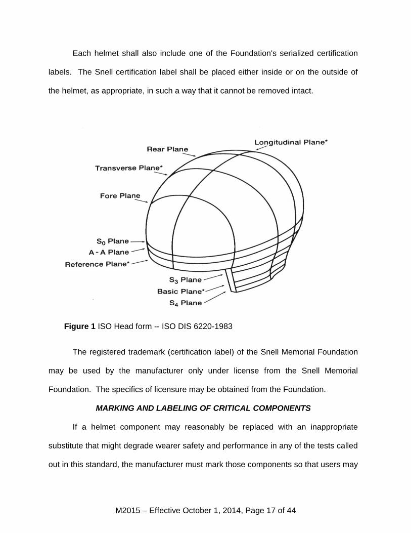
Figure 1 ISO Head form -- ISO DIS 6220-1983
M2015 – Effective October 1, 2014, Page 18 of 44
avoid the purchase and use of inappropriate replacement parts. In particular, face
shields on full face helmets must be marked to identify the manufacturer and the
month and year of manufacture.
HEAD FORMS
This standard invokes six standard head forms for helmet inspection, marking
and testing. The geometry of these head forms is according to the definitions for the
‘A’, ‘C’, ‘E’, ‘J’, ‘M’, and ‘O’ head forms described in International Standards
Organization (ISO) Draft Standard ISO DIS 6220-1983. The impact mass
specifications for the impact test phase are comparable to those in ECE 22-05 for
these same head form designations.
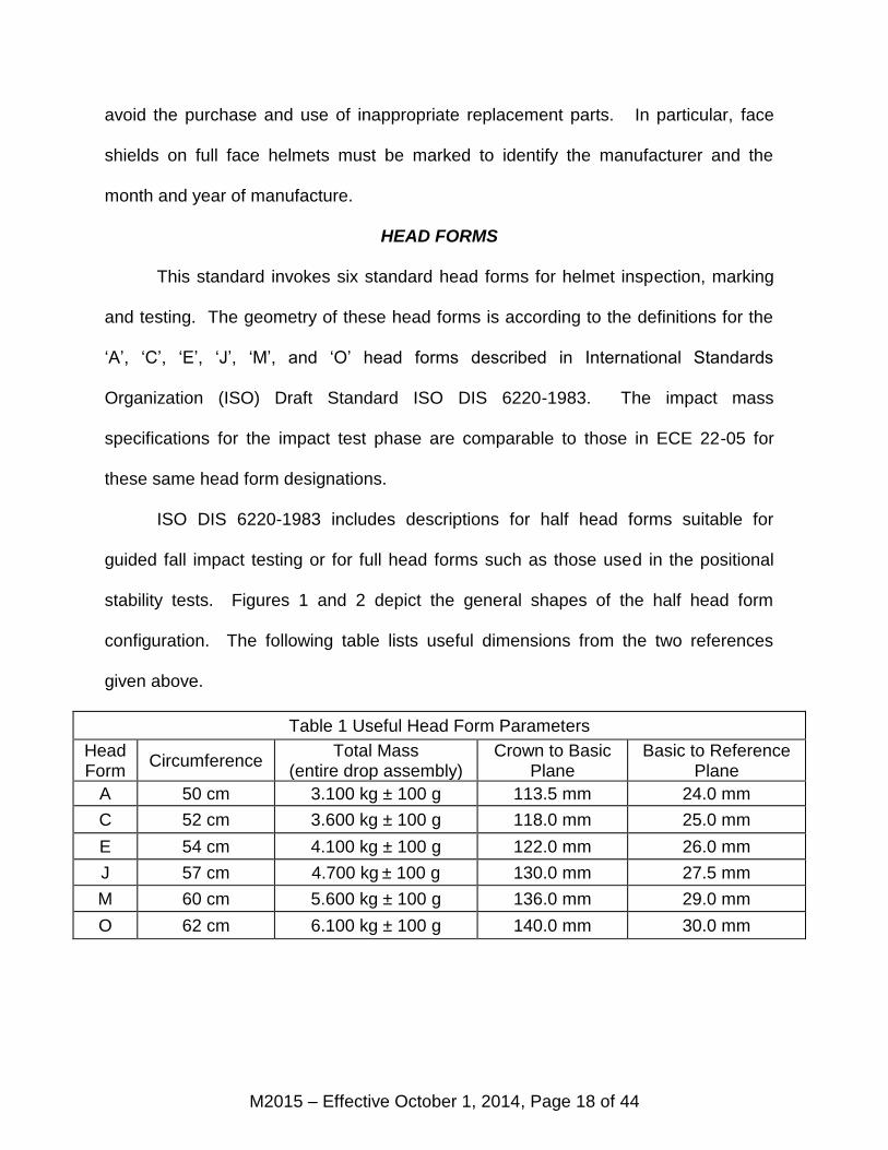
ISO DIS 6220-1983 includes descriptions for half head forms suitable for
guided fall impact testing or for full head forms such as those used in the positional
stability tests. Figures 1 and 2 depict the general shapes of the half head form
configuration. The following table lists useful dimensions from the two references
given above.
Table 1 Useful Head Form Parameters
Head Form
Circumference Total Mass
(entire drop assembly) Crown to Basic
Plane Basic to Reference
Plane
A 50 cm 3.100 kg ± 100 g 113.5 mm 24.0 mm
C 52 cm 3.600 kg ± 100 g 118.0 mm 25.0 mm
E 54 cm 4.100 kg ± 100 g 122.0 mm 26.0 mm
J 57 cm 4.700 kg ± 100 g 130.0 mm 27.5 mm
M 60 cm 5.600 kg ± 100 g 136.0 mm 29.0 mm
O 62 cm 6.100 kg ± 100 g 140.0 mm 30.0 mm
M2015 – Effective October 1, 2014, Page 19 of 44
EXTENT OF PROTECTION
The extent of protection corresponds to that region of the head for which
protection is sought. There are a number of planes fixed in the geometry of these
head forms as shown in Figure 1. This description of the extent of protection uses the
ISO definitions of the basic plane, the longitudinal plane, the transverse plane and the
reference plane. Other planes have also been defined strictly for convenience and
clarity.
The basic plane corresponds to the anatomical plane (Frankfort plane) that
includes the auditory meatuses and the inferior orbital rims. The reference plane is
above and parallel to the basic plane. The longitudinal or midsagittal plane is
perpendicular to the basic plane and is the plane of symmetry dividing the right half of
the head form from the left. The transverse or coronal plane is perpendicular to both
the longitudinal and basic planes. It corresponds to the anatomical plane that
contains the two auditory meatuses and divides the front from the rear portions of the
head.
These planes are all well known entities. Several other planes, however, have
proven useful. The S0 plane is parallel to the basic plane and lies above it at a
distance determined by the size of the head form. The S3 plane is parallel to the S0
plane and the basic plane and lies between them. The S4 plane is also parallel to
these planes and lies below the basic plane.
M2015 – Effective October 1, 2014, Page 20 of 44
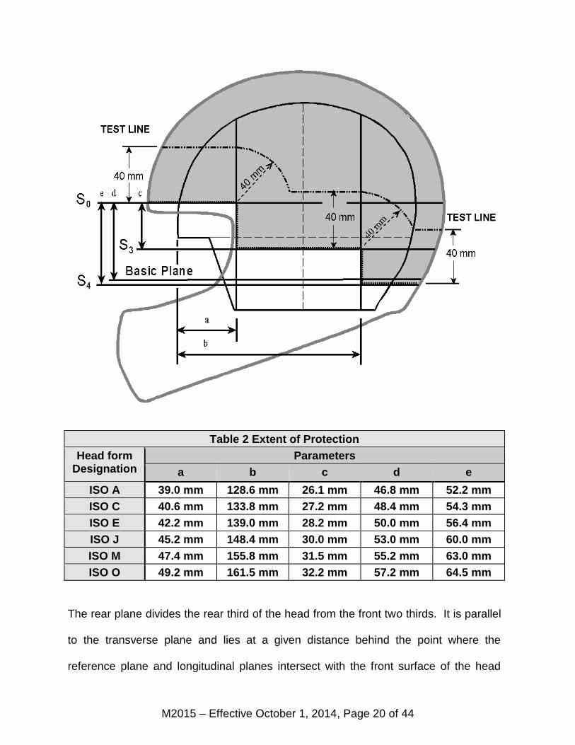
Table 2 Extent of Protection
Head form Designation
Parameters
a b c d e
ISO A 39.0 mm 128.6 mm 26.1 mm 46.8 mm 52.2 mm
ISO C 40.6 mm 133.8 mm 27.2 mm 48.4 mm 54.3 mm
ISO E 42.2 mm 139.0 mm 28.2 mm 50.0 mm 56.4 mm
ISO J 45.2 mm 148.4 mm 30.0 mm 53.0 mm 60.0 mm
ISO M 47.4 mm 155.8 mm 31.5 mm 55.2 mm 63.0 mm
ISO O 49.2 mm 161.5 mm 32.2 mm 57.2 mm 64.5 mm
The rear plane divides the rear third of the head from the front two thirds. It is parallel
to the transverse plane and lies at a given distance behind the point where the
reference plane and longitudinal planes intersect with the front surface of the head
Figure 2 Extent of Protection
M2015 – Effective October 1, 2014, Page 21 of 44
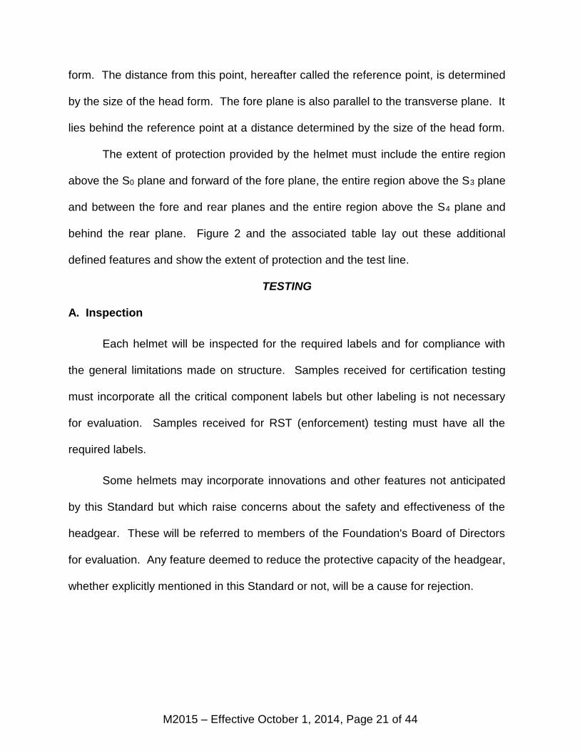
form. The distance from this point, hereafter called the reference point, is determined
by the size of the head form. The fore plane is also parallel to the transverse plane. It
lies behind the reference point at a distance determined by the size of the head form.
The extent of protection provided by the helmet must include the entire region
above the S0 plane and forward of the fore plane, the entire region above the S3 plane
and between the fore and rear planes and the entire region above the S4 plane and
behind the rear plane. Figure 2 and the associated table lay out these additional
defined features and show the extent of protection and the test line.
TESTING
A. Inspection
Each helmet will be inspected for the required labels and for compliance with
the general limitations made on structure. Samples received for certification testing
must incorporate all the critical component labels but other labeling is not necessary
for evaluation. Samples received for RST (enforcement) testing must have all the
required labels.
Some helmets may incorporate innovations and other features not anticipated
by this Standard but which raise concerns about the safety and effectiveness of the
headgear. These will be referred to members of the Foundation's Board of Directors
for evaluation. Any feature deemed to reduce the protective capacity of the headgear,
whether explicitly mentioned in this Standard or not, will be a cause for rejection.
M2015 – Effective October 1, 2014, Page 22 of 44
B. Head Forms and Helmet Positioning
The determination of which head forms are appropriate to a helmet is based on
the specified smallest and largest head circumferences for the helmet. For samples
submitted for certification, this specification must include the smallest and largest
values of head circumference for every possible fit pad configuration of the helmet.
For helmets received for RST testing, the smallest and largest head circumferences
will be taken directly from the helmet label.
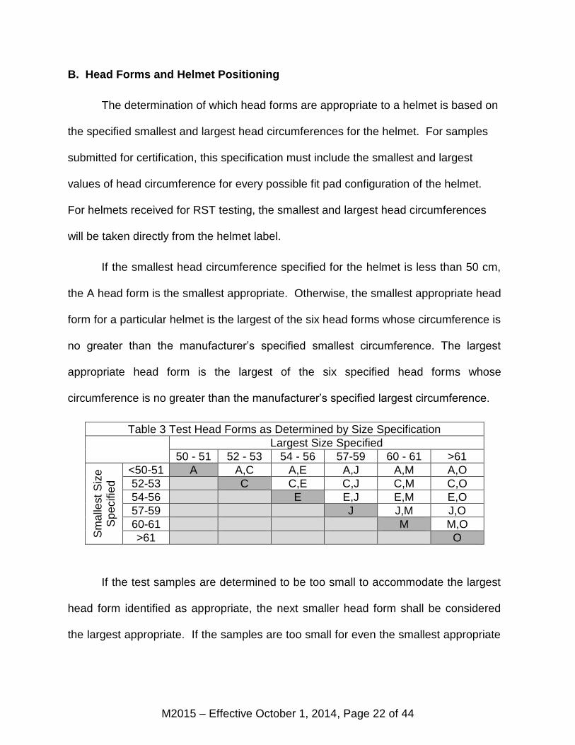
If the smallest head circumference specified for the helmet is less than 50 cm,
the A head form is the smallest appropriate. Otherwise, the smallest appropriate head
form for a particular helmet is the largest of the six head forms whose circumference is
no greater than the manufacturer’s specified smallest circumference. The largest
appropriate head form is the largest of the six specified head forms whose
circumference is no greater than the manufacturer’s specified largest circumference.
Table 3 Test Head Forms as Determined by Size Specification Largest Size Specified
50 - 51 52 - 53 54 - 56 57-59 60 - 61 >61
Sm
alle
st
Siz
e
Sp
ecifie
d
<50-51 A A,C A,E A,J A,M A,O
52-53 C C,E C,J C,M C,O
54-56 E E,J E,M E,O
57-59 J J,M J,O
60-61 M M,O
>61 O
If the test samples are determined to be too small to accommodate the largest
head form identified as appropriate, the next smaller head form shall be considered
the largest appropriate. If the samples are too small for even the smallest appropriate
M2015 – Effective October 1, 2014, Page 23 of 44
head form as indicated by the manufacture specification, the samples shall be
rejected for certification.
The table shows which head forms will be used in certification testing for
various head size specifications. Since the largest head size should never be smaller
than the smallest head size, most of the lower left region of the table is blank.
If the size specification corresponds to one of the gray cells along the table’s
main diagonal, only a single test head form will be necessary and the manufacturer
need only submit five samples identical samples configured with comfort padding for
the largest intended head size for certification testing. Otherwise, two more samples
are required, identical to the first five in all respects except that the comfort padding
must be configured for the smallest intended head size.
During testing, helmets will be positioned on the selected test head form
according to the manufacturer’s specified helmet positioning indices. If the
manufacturer fails to provide positioning information with certification samples, the
helmets will be positioned according to the best judgment of the authorized technical
personnel. If the helmets meet certification requirements, the helmet positioning
indices will be those used in all future testing.
These helmet positioning indices represent distances on the front of the head
form from the basic plane along the intersection with the longitudinal plane upward to
the lower brow edge of the helmet. Helmet positioning indices will be assigned for all
head form sizes appropriate to the headgear. Each headgear could conceivably
M2015 – Effective October 1, 2014, Page 24 of 44
require as many as six helmet positioning indices, one each for the ‘A’, ‘C’, ‘E’, ‘J’, ‘M’
and ‘O’ head forms.
C. Marking
The helmet is placed upon the largest appropriate ISO head form, positioned
according to the apposite helmet positioning index and held in place with an applied
force of 50 newtons (11.25 lbs). The intersections of the shell with the various defined
planes are then traced onto the outer surface of the helmet in the following manner:
The level of the S0 plane is marked on that portion of the helmet in front of the
fore plane. The level of the S3 plane is marked on that portion lying between the fore
and rear planes. The level of the S4 plane is marked on that portion behind the rear
plane. Finally, line segments along the fore plane are marked to join the S0 and S3
planes and, similarly, line segments along the rear plane are marked to join the S3 and
S4 planes.
These lines enclose the top of the helmet and are the boundary of the required
extent of protection. However, it shall not be a cause for rejection if parts of this
boundary fall below the edge of the helmet. A test line shall be constructed within the
extent of protection 40 mm from the closest point on the boundary as shown in figure
2.
If identical helmets are to be configured with different thicknesses of comfort
padding to accommodate different ranges of head size, the required extent of
protection marked on the test samples shall include the required extent of protection
for each different configuration as marked on the largest head form appropriate for
M2015 – Effective October 1, 2014, Page 25 of 44
each. That is: the helmet must meet all the requirements of this Standard in each of
the intended configurations.
D. Peripheral Vision
The clearance for peripheral vision will be checked by placing the helmet on
each appropriate ISO head form, positioning it according to the apposite helmet
positioning index and holding it in place with a force of 50 newtons. The clearance
must include the following solid angles to the front of the head form:
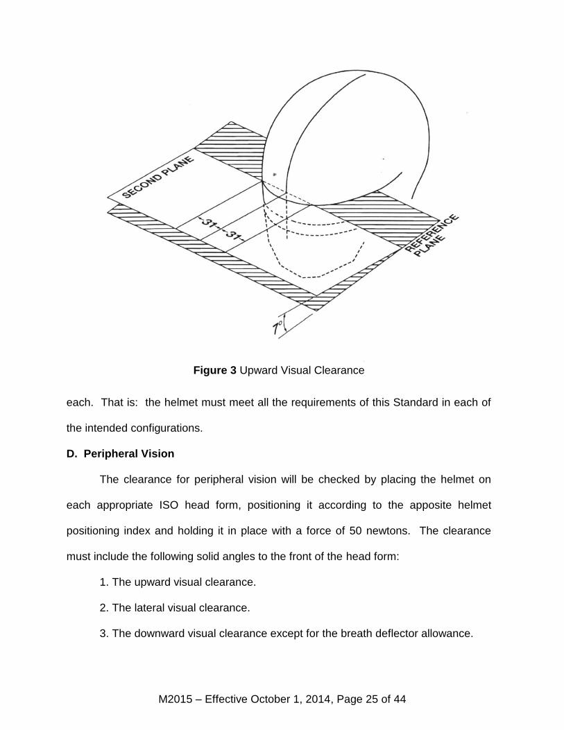
1. The upward visual clearance.
2. The lateral visual clearance.
3. The downward visual clearance except for the breath deflector allowance.
Figure 3 Upward Visual Clearance
M2015 – Effective October 1, 2014, Page 26 of 44
Helmets certified to a special addendum to this standard and bearing the
warning labels specified in the addendum will not be subjected to the following
procedures and criteria for evaluating clearances for vision. However, the procedures
and criteria specified in the addendum will be applied instead.
The upward visual clearance is the solid angle bounded by the reference plane
of the head form and a second plane tilted 7º up from the reference plane. This
second plane intersects the reference plane at two points on the front surface of the
head form that are 31 mm to the right and left of the longitudinal plane as shown in
figure 3.
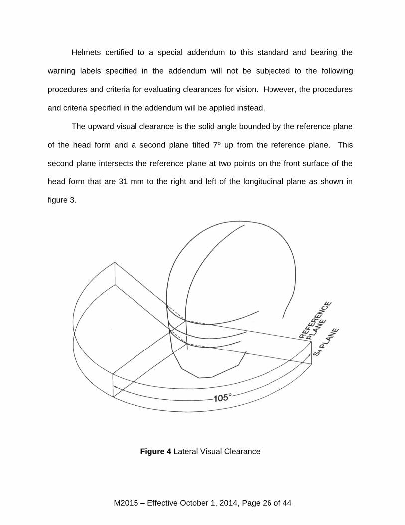
Figure 4 Lateral Visual Clearance
M2015 – Effective October 1, 2014, Page 27 of 44
The lateral visual clearance, as shown in figure 4, is the solid angle bounded by
the reference plane, the S4 plane and two more planes that are perpendicular to the
reference plane and that contain the reference point on the front of the head form.
One of these two planes forms an angle of 105º with the longitudinal plane and lies to
the left of the head form. The other forms the same angle to the right of the head
form.
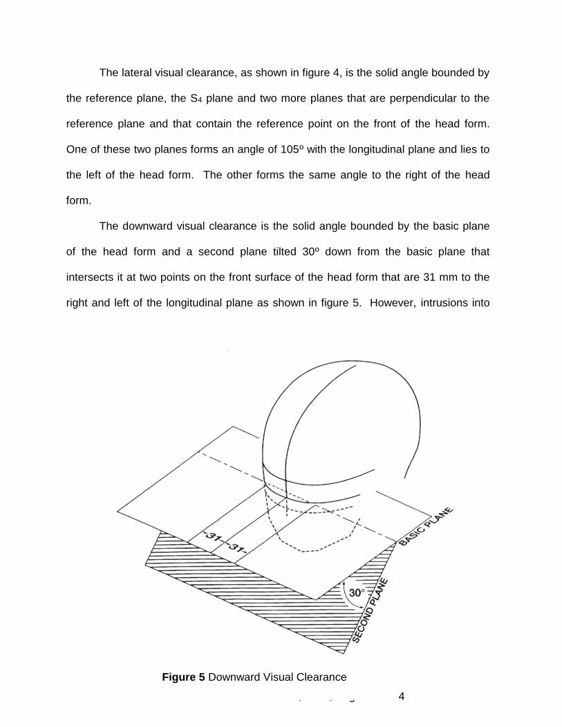
The downward visual clearance is the solid angle bounded by the basic plane
of the head form and a second plane tilted 30º down from the basic plane that
intersects it at two points on the front surface of the head form that are 31 mm to the
right and left of the longitudinal plane as shown in figure 5. However, intrusions into
Figure 5 Downward Visual Clearance
M2015 – Effective October 1, 2014, Page 28 of 44
this downward clearance are permitted so long as the intrusions are within the breath
deflector allowance.
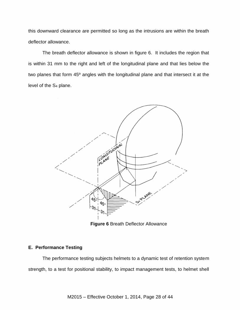
The breath deflector allowance is shown in figure 6. It includes the region that
is within 31 mm to the right and left of the longitudinal plane and that lies below the
two planes that form 45º angles with the longitudinal plane and that intersect it at the
level of the S4 plane.
E. Performance Testing
The performance testing subjects helmets to a dynamic test of retention system
strength, to a test for positional stability, to impact management tests, to helmet shell
Figure 6 Breath Deflector Allowance
M2015 – Effective October 1, 2014, Page 29 of 44
penetration tests, to a removability test, and to chin bar and face shield tests if
appropriate. These tests are conducted upon helmet samples kept under laboratory
ambient temperature and humidity or that have been conditioned in one of three
environments simulating some of the conditions in which the helmet might reasonably
be expected to be used.
Prior to conditioning and testing, samples may be exposed to solvents common
to motorsports which have been found to attack and degrade some helmet
components.
In certification testing, four samples are required for testing on the largest
appropriate head form. The first of these is kept at laboratory ambient temperature
and humidity and allowed to come to equilibrium. It is subjected first to the positional
stability test and then to the impact management and other tests. The second, third
and fourth samples are conditioned hot, cold and wet, and subjected to the dynamic
test of the retention system, the impact management test and the other tests. If the
smallest appropriate head form is not the same as the largest, two additional samples
are required for testing on this head form. The first of these will be allowed to stabilize
at laboratory ambient temperature and humidity and then will be subjected to the test
for positional stability. This sample may then be conditioned hot or cold or kept at
laboratory ambient for impact testing. The second additional sample shall be tested in
impact conditioned hot, cold or wet or kept at lab ambient according to the best
judgment of the test personnel.
The selection of tests, conditioning and special conditioning is left to the
discretion of the Foundation's technical personnel. However, for certification testing,
M2015 – Effective October 1, 2014, Page 30 of 44
each of the specified tests shall be applied to at least one sample. Furthermore, it is
expected that all testing will be conducted so as to exercise all the likely failure modes
of the helmet.
E1. Conditioning for Testing
Test samples may be kept at laboratory ambient temperature and humidity or
may be conditioned cold, hot or wet according to the specifications given below. At
the discretion of the Foundation's technical personnel and at any point during the
testing, a sample previously kept at ambient may be conditioned cold, hot or wet.
However, once a sample has been conditioned cold, hot or wet, the sample must be
maintained in that condition throughout the rest of the testing.
The special solvent wipe conditioning described below may be applied to any
sample at the discretion of the Foundation's technical personnel.
a. Special Conditioning. Prior to any impact or retention system testing
helmets may first be conditioned with a solvent mix of 50% toluene and 50%
isooctane. A cotton cloth or suitable substitute shall be soaked in the solvent and
used as an applicator. The solvent will be applied to the shell first in an area within 5
mm of the chin strap attachments for not less than five (5) seconds on each side and
then applied to the remainder of the shell for not less than ten (10) seconds. At least
thirty minutes shall elapse before further conditioning and testing.
b. Cold. The sample shall be conditioned by being exposed to a temperature
of -20 ±2º C for a period of not less than four (4) hours, or more than twenty-four (24)
hours.
M2015 – Effective October 1, 2014, Page 31 of 44
c. Heat. The sample shall be conditioned by being exposed to a temperature
of 50 ±2º C for a period of not less than four (4) hours, or more than twenty-four (24)
hours.
d. Wet. The sample shall be conditioned by being continuously sprayed with
water at a temperature of 25 ±5º C for a period of not less than four (4) hours, or more
than twenty-four (24) hours. This spray shall be directed at the helmet's external
surfaces. The helmet shall not be subjected to total immersion.
All testing of these hot, cold and wet helmets shall begin within two (2) minutes
from the time of removal from the conditioning apparatus. The samples shall be
returned to the conditioning apparatus between tests.
E2. Positional Stability (Roll-Off)
The test for positional stability shall only be applied to samples kept at ambient
laboratory temperature and humidity. The helmet shall not have been subjected to
any prior performance testing.
The helmet shall be tested on the smallest appropriate standard full-face head
form. The head form shall be supported on a stand so that its vertical axis points
downward at an angle of 135º to the direction of gravity. The head form shall be
oriented face down. The helmet shall be placed on the head form and adjusted to
obtain the best configuration of the retention system. An inelastic strap shall be
hooked to the edge of the helmet at the rear centerline and brought forward so that its
free end hangs downward across the top of the helmet. An inertial hammer shall be
suspended from the free end of the strap. This inertial hammer shall enable a 4.0 kg
±50 g mass to be dropped through a 0.6 m guided fall in order to deliver an abrupt
M2015 – Effective October 1, 2014, Page 32 of 44
shock load to the headgear. The shock load will force the helmet to rotate forward on
the head form. The helmet may be shifted but must remain on the head form.
The head form shall be repositioned so that it is facing upward but with the
vertical axis still oriented downward at 135º to gravity. The helmet shall be positioned
and adjusted to obtain the best configuration of the retention system. The
strap/inertial hammer shall be hooked to the brow edge of the helmet at the center line
so that the strap lies along the centerline and the hammer is suspended from the top
of the helmet. The shock weight shall be dropped through the 0.6 m guided fall
delivering an abrupt shock load forcing the helmet to rotate rearward. The helmet may
be shifted but must remain on the head form.
The entire portion of the inertial hammer assembly that participates in the
loading of the helmet shall be such that its mass is no more than 5.0 kg including the
4.0 kg shock mass.
E3. Dynamic Test of Retention System
The dynamic test of the retention system may be applied to any sample either
kept at ambient temperature and humidity or conditioned hot, cold or wet. This test
may be performed before, after, or between any of the other procedures in the test
sequence. However, the retention test shall not be valid if an integral chin bar has
been removed from a full face helmet.
The helmet shall be supported on its lower shell edge in such a manner that the
chin strap may be fastened under a device whose upper end approximates the
contour of the bony structure of the jaw. The device will then be given a mechanical
pre-load followed by a dynamic loading. The retention system fails if it cannot support
M2015 – Effective October 1, 2014, Page 33 of 44
the mechanical loads or if the maximum deflection during the dynamic load exceeds
30 mm. The retention system also fails if it cannot be easily and quickly unfastened
after testing.
If the technician determines that the helmet cannot be adequately supported on
its lower shell edge, at his discretion, he may support the helmet on a head form for
this test.
a. This chinstrap loading device shall consist of a simulated jaw and
accommodations for the pre-load and dynamic load. The jaw portion shall consist of
two metal bars or rollers, each one 12.7 ±0.5 mm in diameter, separated by 76 ±0.5
mm on center. The mass of this device shall not exceed 6.0 kg.
b. A pre-load shall be applied for at least 60 seconds. This pre-load shall
consist of the mass of the chin strap loading device, static load of 23 kg and the shock
load of 38 kg ± 500g which will total 61 kg ±500 g.
c. Raise the 38 kg ±500 g mass which will then be dropped in a vertical guided
fall through a distance of 120 mm to load the retaining system abruptly; the shock load
of 38 kg mass and static load of 23 kg mass shall not be additive. In order to protect
the test mechanism, the impact of the 38 kg mass may be cushioned with a 00-93
durometer rubber pad 150 mm in diameter by 6½ mm thick, or its equivalent.
E4. Impact Management Tests
The impact management tests may be performed on samples kept at ambient
temperature and humidity or conditioned hot, cold or wet. The sample shall not have
been subjected to the shell penetration test beforehand.
M2015 – Effective October 1, 2014, Page 34 of 44
These tests involve a series of controlled impacts in which the helmet is
positioned on a test head form. The helmeted head form is then dropped in guided
falls onto specified test anvils. The impact site and the impact energy must meet
certain requirements in order for the tests to be valid.
If the sample is so constructed that it interferes with the test equipment
preventing impacts at sites within the test line, then, at the discretion of the
Foundation's technical personnel, parts of the helmet may be cut away to facilitate
testing. Every reasonable effort to minimize such cutting will be made. However,
there shall be no relaxation of the impact levels or of the test criteria.
Certain tests shall not be valid when performed on samples that have been cut
for impact testing: the dynamic strength of retention system test of section E3., the
positional stability test of section E2., the chin bar test of section E5. and the
removability test of section E8.
Special considerations apply when the helmet is a “flip-up” model, that is:
configured with a chin bar that pivots up and away from the face of the wearer. For
the first three impacts on any flip-up sample, the impact tests will be performed with
the chin bar locked in the closed position. In these tests the chin bar must not release
and “flip-up” inadvertently. In certification testing, the tests will be structured so as to
investigate performance in frontal followed by lateral impact.
E4.1 Impact Management Test Equipment
The test equipment shall consist of at least the following items:
a. The smallest and largest of the head forms appropriate for the helmet
sample. This head form shall be of rigid, low resonance metal such as magnesium
M2015 – Effective October 1, 2014, Page 35 of 44
alloy and shall conform to the 'A', 'C', 'E', 'J', 'M' or 'O' geometries specified in ISO DIS
6220-1983.
b. A ball-arm/collar assembly which is fitted to a socket machined into the base
of the head form. The ball/socket configuration shall be such that the geometrical
center of the ball is located on the central vertical axis of the head form 12.7 mm
above the reference plane as described in ISO DIS 6220-1983. The ball-arm/collar
assembly shall also include a uniaxial accelerometer fixed firmly into the ball.
c. A head form support assembly rigidly attached to the ball-arm. This support
assembly shall be such that it and consequently the head form may be guided in a
vertical drop. The mass of this support assembly shall not exceed 1.2 kg. The total
mass of the head form plus ball-arm/collar assembly plus head form support assembly
shall be within 100 grams of: 3.1 kg for the ISO A head form, 3.6 kg for the ISO C
head form, 4.1 kg for the ISO E head form, 4.7 kg for the ISO J head form, 5.6 kg for
the ISO M head form and 6.1 kg for the ISO O head form.
d. A guidance system such that the head form/support assembly is guided in a
vertical drop onto a test anvil. This guidance system may consist of two or more wires
or one or more rails. The head form/support - guidance system - test anvil alignment
shall be such that:
d1. The drop trajectory shall be a straight line within 3º of vertical and within 5º
of the sensitive axis of the uniaxial accelerometer.
d2. The line parallel to the drop trajectory and passing through the center of
the head form ball-socket shall pass within 5 mm of the center of the test anvil, within
10 mm of the center of gravity of the head form/support assembly, and within 5 mm of
M2015 – Effective October 1, 2014, Page 36 of 44
the sensitive element of the uniaxial accelerometer.
e. A rigid anvil mount consisting of a solid mass of at least 500 kg. The upper
surface of the anvil mount shall consist of a steel plate with a minimum thickness of 12
mm and a minimum surface area of 0.10 m2.
f. Three test anvils: flat, hemispherical and edge.
f1. The flat anvil shall have a minimum surface area of 0.0127 m2, e.g. 127
mm diameter face. When fixed in position on the anvil mount, the surface shall be
perpendicular to the head form trajectory.
f2. The hemispherical anvil shall have a 48 ±0.5 mm radius.
f3. The edge anvil shall have a striking face 6.3 mm wide with a depth of at
least 35 mm. The radius of the edges on the impact face shall not exceed 0.5 mm.
When in position, the striking face shall be perpendicular to the head form trajectory.
The anvil shall be sufficiently long that the ends do not contact the helmet during
impact.
g. A uniaxial accelerometer. The acceleration data channel must comply with
SAE recommended practice J 211 requirements for channel class 1000 with the
exception that the frequency response need not include the range from dc to 10 hz
which may not be obtainable using certain types of transducers.
h. A velocity measurement device which will yield the velocity of the head
form/support assembly within the last 40 mm of travel before impact. The velocity
measurement must be accurate to within ±1%.
M2015 – Effective October 1, 2014, Page 37 of 44
E4.2 Test Definitions
a. The impact site refers to the portion of the helmet struck during an impact
test. It is defined as the point where a line passing through the center of the head
form ball and the center of the anvil intersects the outer surface of the helmet at the
instant the helmet first touches the anvil.
b. The impact velocity is the velocity of the head form/support assembly as
measured within no more than 4 cm of the first contact between the helmet and the
impact surface.
c. This standard specifies nominal impact velocities which must be adjusted in
order to allow for deviations between the actual mass of the test head form assembly
and the specified ideal value. The actual test impact velocity shall be the specified
nominal velocity multiplied by the square root of the value obtained by dividing the
ideal head form assembly mass by the actual mass. For example, if, for the ‘A’ head
form, the mass of the head form plus ball-arm/collar and support assembly as in
paragraph E4.1c masses 3.2 kg instead of the ideal mass of 3.1 kg, the test impact
velocities shall be obtained by multiplying the nominal velocities by a factor of 0.984.
d. There are two levels of test: the first is the standard level used to identify
those helmets which definitely meet this standard. It is applied to samples submitted
for certification testing and to those acquired for the Foundation’s random sample test
(RST) program. The second is the deviation level which is applied to samples
acquired for second round RST procedures, that is: testing of samples of currently
certified models for which previous samples have obtained failing results in RST
M2015 – Effective October 1, 2014, Page 38 of 44
testing. Failure to meet test criteria at the deviation levels indicates that the sample
definitely does not meet the requirements of the standard.
E4.3 Test Impacts
Test impact sites shall be on or above the test line. Rivets, vents and any other
helmet feature within this region shall be valid test sites. Each impact site will be
subjected to a group of one or two impacts according to the anvil selected for that site.
The impact site for the first impact within in a group is the target for the
successive impacts in the same group. However, if an impact group is sited closer
than 120 mm to any previous impact group, that later impact shall be declared invalid.
There is no restriction regarding test anvil selection. The impact velocities for
each test impact depend on the type of test and on the head form designation.
Second impacts do not apply to helmets in tests against the edge anvil.
The technician may select either the largest or smallest appropriate head form
for any particular group of impacts. In all cases the technician may impact any site on
the helmet surface on or within the test lines as drawn for any of the head forms
considered appropriate for that helmet.
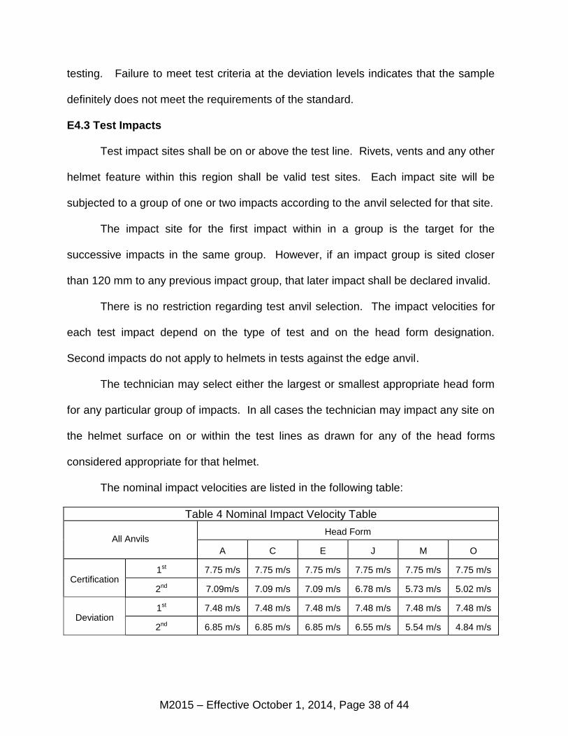
The nominal impact velocities are listed in the following table:
Table 4 Nominal Impact Velocity Table
All Anvils Head Form
A C E J M O
Certification 1st 7.75 m/s 7.75 m/s 7.75 m/s 7.75 m/s 7.75 m/s 7.75 m/s
2nd 7.09m/s 7.09 m/s 7.09 m/s 6.78 m/s 5.73 m/s 5.02 m/s
Deviation 1st 7.48 m/s 7.48 m/s 7.48 m/s 7.48 m/s 7.48 m/s 7.48 m/s
2nd 6.85 m/s 6.85 m/s 6.85 m/s 6.55 m/s 5.54 m/s 4.84 m/s
M2015 – Effective October 1, 2014, Page 39 of 44
a. Each site tested against the flat anvil shall be tested according to the values
in the impact velocity table adjusted for the mass of the head form assembly.
b. Each site tested against the hemispherical anvil shall be tested according to
the values in the impact velocity table adjusted for the mass of the head form
assembly.
c. Each site tested against the edge anvil shall be tested according to the
values in the impact velocity table adjusted for the mass of the head form assembly.
No helmet shall be subjected to the second impact for this anvil.
d. If the impact velocity for any test impact exceeds the specified mass
adjusted velocity by more than 1.5%, that impact shall be declared invalid.
Please Note: The impacts described above are based on specific velocities
and not prescribed drop heights. To attain the proper velocity for an impact, it is likely
that the drop height will need to be adjusted to compensate for frictions inherent in
most mechanical helmet testing systems. Height adjustments for these frictions should
not account for more than 10% of the total drop height. Also, the 1.5% margin allowed
for impact velocity reflects the uncertainties expected even for well maintained drop
equipment. It is expected that drop heights will always be selected to produce, as
closely as possible, the precise impact velocity as called out in the standards and
adjusted for head form assembly drop mass.
M2015 – Effective October 1, 2014, Page 40 of 44
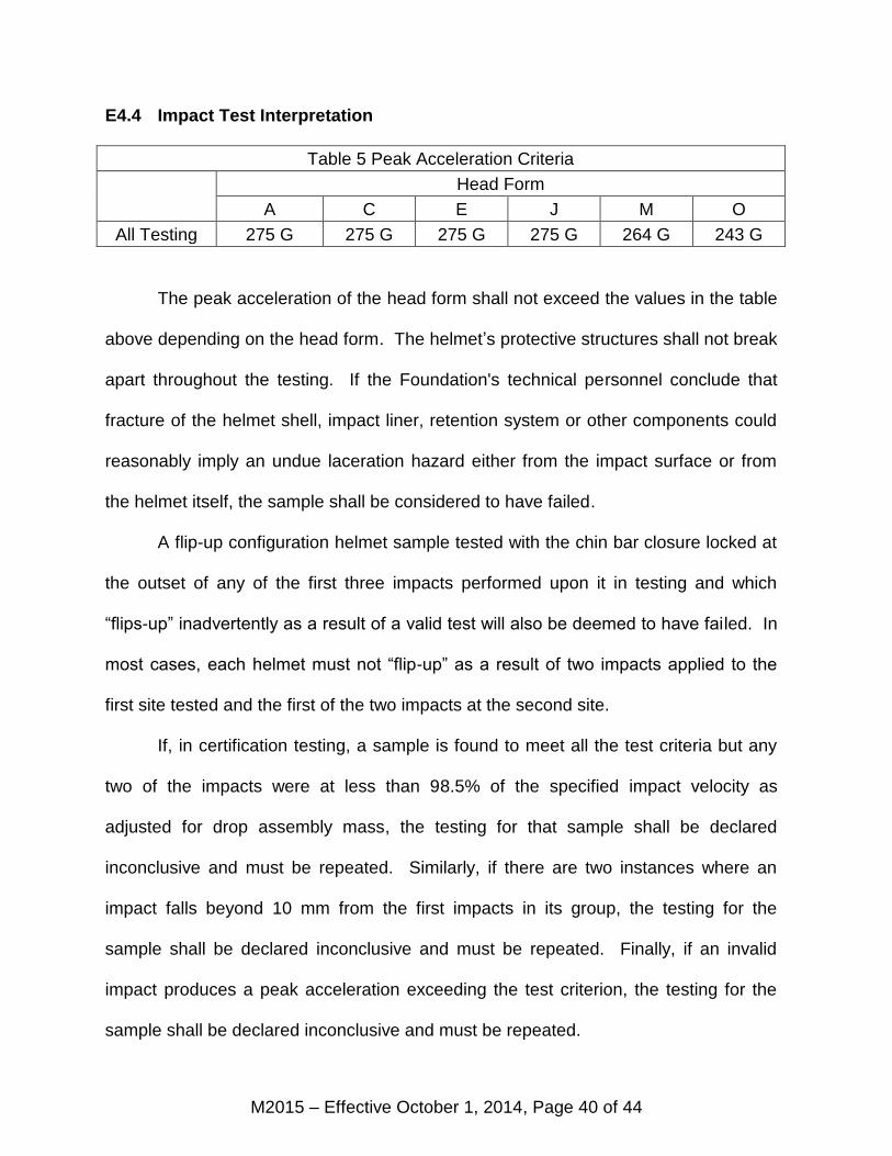
E4.4 Impact Test Interpretation
Table 5 Peak Acceleration Criteria
Head Form
A C E J M O
All Testing 275 G 275 G 275 G 275 G 264 G 243 G
The peak acceleration of the head form shall not exceed the values in the table
above depending on the head form. The helmet’s protective structures shall not break
apart throughout the testing. If the Foundation's technical personnel conclude that
fracture of the helmet shell, impact liner, retention system or other components could
reasonably imply an undue laceration hazard either from the impact surface or from
the helmet itself, the sample shall be considered to have failed.
A flip-up configuration helmet sample tested with the chin bar closure locked at
the outset of any of the first three impacts performed upon it in testing and which
“flips-up” inadvertently as a result of a valid test will also be deemed to have failed. In
most cases, each helmet must not “flip-up” as a result of two impacts applied to the
first site tested and the first of the two impacts at the second site.
If, in certification testing, a sample is found to meet all the test criteria but any
two of the impacts were at less than 98.5% of the specified impact velocity as
adjusted for drop assembly mass, the testing for that sample shall be declared
inconclusive and must be repeated. Similarly, if there are two instances where an
impact falls beyond 10 mm from the first impacts in its group, the testing for the
sample shall be declared inconclusive and must be repeated. Finally, if an invalid
impact produces a peak acceleration exceeding the test criterion, the testing for the
sample shall be declared inconclusive and must be repeated.
M2015 – Effective October 1, 2014, Page 41 of 44
The impact test procedures leave considerable latitude to the helmet tester
regarding site and anvil selection. It is expected that the tester will orchestrate each
standard test series in order to investigate potential weaknesses and to exercise each
likely failure mode and will conduct deviation level testing to exercise the failure
modes identified previously.
If at the end of a certification test series, the Foundation's technical personnel
conclude that the results obtained in valid impacts are not sufficient to determine
whether the helmet model meets the performance requirements of this standard,
additional samples may be conditioned and tested. It is expected that all samples
submitted will meet all the test requirements.
E5. Chin Bar Test
The chin bar test applies to full face helmets only. At least one helmet in each
certification series shall be tested. The helmet shall be firmly mounted on a rigid base
so that the chin bar faces up and the reference plane is at 65 ±5º from horizontal. A
mass of 5 ± .2 kg with a flat striking face of 0.01 m5 minimum area shall be dropped in
a guided fall so as to strike the central portion of the chin bar with an impact velocity of
3.5 ±0.2 m/sec. The maximum downward deflection of the chin bar must not exceed
60 mm nor shall any component fail so as to cause a potential injury to the wearer.
E6. Shell Penetration Test
The shell penetration test may be applied to helmets kept at laboratory ambient
temperature and humidity or helmets conditioned hot, cold or wet. At least one helmet
sample shall be tested in shell penetration. The complete helmet shall be placed on a
rigidly mounted head form. The test head form for the penetration test need not be
M2015 – Effective October 1, 2014, Page 42 of 44
the standard ISO head form shape used in the impact testing and helmet marking. It
is expected only that the device used will provide reasonable support for the helmet
and conformance with the interior of the helmet immediately beneath the site of the
penetration test. If the helmet contains a sling or some other adjustable sizing
component, it shall be relaxed to its most extendable position.
The penetration test striker shall have a mass of 3 kg ±50 g and the point of the
striker shall be a cone with an included angle of 60º ±0.5º and an altitude of 38 ±0.38
mm. The striking tip shall have a hardness of 60 Rockwell (scale C ± 3 points) and a
radius of 0.5 ± 0.1 mm. The region of the support head form directly beneath the
striker tip shall be wax or soft plastic so and covered with a thin tell-tale of paper, foil,
tape or some similar material.
The striker shall be dropped to strike the surface of the helmet shell at a
velocity of 7.45 ± 0.15 meters per second as measured when the striker is no more
than 4 centimeters away from contact with the helmet. The helmet may be oriented on
the support head form so that the test striker is directed at any site on or above the
test line but the penetration test site must be at least 7.5 cm removed from the center
of any impact test site or any other penetration test site. At the test technician’s
discretion, samples may be tested at more than one site on the shell.
For all penetration tests performed, the test striker must not penetrate through
the helmet wall so as to put a hole in the tell-tale between the helmet and the support
head form.
M2015 – Effective October 1, 2014, Page 43 of 44
E7. Face Shield Penetration Test
If a face shield is provided with a full face helmet, this face shield shall be
tested for penetration resistance in the following manner:
The face shield shall be tested on the appropriate helmet, correctly deployed
across the facial opening and under laboratory ambient conditions. A soft lead pellet
weighing 1 ±0.1 g with a diameter of 5.5 ±0.1 mm and traveling at a velocity of 500
±20 km per hour shall strike the face shield normal to the surface. The face shield
shall be tested in at least three different locations: the center line and 80 ±5 mm to
either side of the center line. The pellet must not penetrate to the interior of the
helmet.
E8. Removability
The helmet removability test determines whether the helmet can be removed
from an unconscious victim without resorting to any buckles, clasps or other
mechanisms which may be rendered non-functional by impact stresses. The helmet is
placed on the largest appropriate complete ISO head form with all the closures and
retention systems engaged. A technician must remove the helmet from the head form
using simple, common hand tools but without accessing any of the helmet
mechanisms.
The hand tools for this test are limited to shears, simple edged tools and flat
bladed screw drivers. The operation must not require more than thirty seconds.
E9. Post-testing Disassembly and Inspection
If a set of helmets is submitted for and passes certification testing, at least one
of the tested samples shall be disassembled and inspected. If the laboratory staff
M2015 – Effective October 1, 2014, Page 44 of 44
identifies any internal feature that is not plausible for inclusion in a production helmet,
the model shall be rejected. If an internal projection on the helmet shell is deemed to
present an undue laceration or puncture hazard, the model shall be rejected. In
evaluating these internal projections, no allowance shall be made for liner thickness.
At the discretion of the technician, any helmet may be disassembled in order to
check for internal projections, plausibility or for deviations from the originally certified
configuration.
Certification Series Test Plan
Certification Test Matrix
Helmets Configured for Largest Intended Size
Helmet Conditioning Appropriate Tests
#1 Archive Ambient Not subject to performance testing
#2 Lab Ambient E2, E5, E7, E4, E6, E8, E9
#3 Wet E3, E5, E7, E4, E6, E8, E9
#4 Cold E3, E5, E7, E4, E6, E8, E9
#5 Hot E3, E5, E7, E4, E6, E8, E9
When Necessary – Helmets Configured for Smallest Intended Size
#6 Cold E2 (prior to cold condition), E5, E4, E6, E8, E9
#7 Hot E3, E5, E7, E4, E6, E8, E9
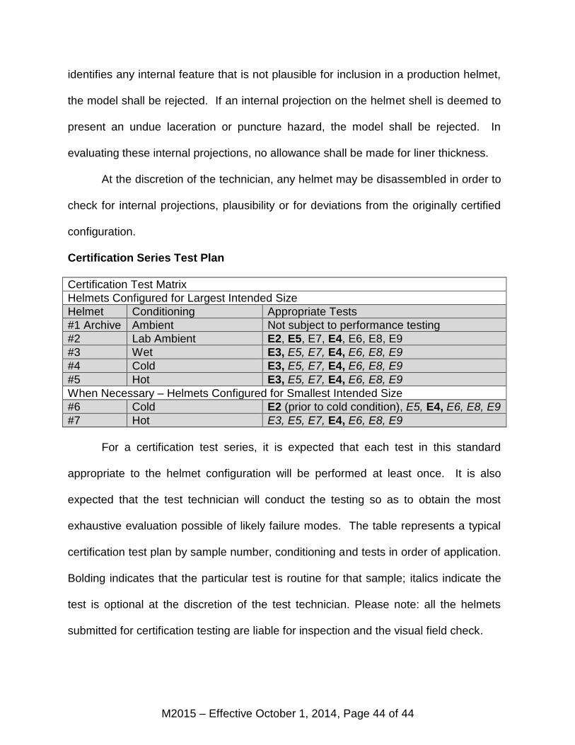
For a certification test series, it is expected that each test in this standard
appropriate to the helmet configuration will be performed at least once. It is also
expected that the test technician will conduct the testing so as to obtain the most
exhaustive evaluation possible of likely failure modes. The table represents a typical
certification test plan by sample number, conditioning and tests in order of application.
Bolding indicates that the particular test is routine for that sample; italics indicate the
test is optional at the discretion of the test technician. Please note: all the helmets
submitted for certification testing are liable for inspection and the visual field check.