Embed Size (px)
Citation preview
For Peer Review O
nly
Archaeological applications of low-cost integrated sidescan
sonar/single-beam echosounder systems in Irish inland waterways
Journal: Archaeological Prospection
Manuscript ID ARP-15-0023.R1
Wiley - Manuscript type: Research Article
Date Submitted by the Author: n/a
Complete List of Authors: Westley, Kieran; University of Southampton, Coastal and Offshore
Archaeological Research Services McNeary, Rory; Department of Agriculture, Environment and Rural Affairs, Northern Ireland
Keywords: sidescan sonar, marine geophysics, shipwreck, underwater archaeology, crannog, logboat
http://mc.manuscriptcentral.com/arp
Archaeological Prospection

For Peer Review O
nly
1
Revised manuscript for submission to Archaeological Prospection
Archaeological applications of low-cost integrated sidescan
sonar/single-beam echosounder systems in Irish inland
waterways
Kieran Westley
1,* and Rory McNeary
2
1Coastal and Offshore Archaeological Research Services, University of Southampton
2Marine and Fisheries Division, Department of Agriculture, Environment and Rural Affairs,
Northern Ireland
*Corresponding Author ([email protected])
Abstract
Inland waterways, such as rivers and lakes have been foci of human settlement and
use for millennia. However, underwater archaeological prospection or survey in these
environments is often hindered by poor or no-visibility conditions. While this can be
overcome using a range of well-established geophysical techniques, their application in
inland waterways seems comparatively less common than in offshore environments.
Possible reasons include the logistical challenges of surveying shallow confined, often
inaccessible and uncharted waters coupled with a wider lack of awareness of the
submerged archaeological potential of inland waterways. This paper demonstrates one
method by which the logistical challenge can be circumvented, specifically the use of
low-cost acoustic systems which combine a single-beam echo sounder and sidescan
sonar. These systems have appeared within the last decade and are smaller and
cheaper than their survey-grade counterparts. Although developed for the sport
fishing community, as shown here, they can also be used for archaeological purposes.
Their effectiveness for archaeological prospection is illustrated via three case studies
from lacustrine and riverine settings in Northern Ireland and by reference to object
detection and bathymetric mapping. The data presented indicate that the low-cost
systems are capable of collecting data that is sufficient for archaeological purposes but
they are best suited to shallow confined waters where their disadvantages (limited
range and depth of operation, reduced image quality) are minimized.
Keywords
Sidescan sonar, marine geophysics, shipwreck, crannog, logboat, underwater
archaeology
Page 1 of 40
http://mc.manuscriptcentral.com/arp
Archaeological Prospection
123456789101112131415161718192021222324252627282930313233343536373839404142434445464748495051525354555657585960

For Peer Review O
nly
2
Introduction
Inland waterways such as rivers and lakes have been the focus of human settlement
and exploitation for millennia. They provide fresh water, a range of subsistence
resources, can form natural transport corridors or defensive barriers and may also
constitute sites of ritual deposition. As a result, they comprise a rich multi-period
archaeological and palaeo-environmental resource, often with organic remains well-
preserved by waterlogging (Coles, 1984; Coles and Coles, 1989; Coles and Lawson,
1987; Brown, 1997; Menotti, 2012; Menotti and O’Sullivan, 2013).
A large proportion of archaeological work has traditionally tended to focus either on
sites currently above-water on the margins of these waterbodies or now-drained areas
where the archaeology no longer lies in, or adjacent to, the former waterbody (e.g.
Hencken, 1950; Collins, 1955; Bradley, 1991; Keane, 1995; Croes et al., 2009;
Fredengren et al., 2010; Conneller et al., 2012; Palomo et al., 2014; Malim et al., 2015).
Based on the published literature, comparatively less appears to have been
accomplished on archaeological material which is presently submerged in inland
waterways.
This relates at least partly to the challenge of undertaking archaeology underwater,
particularly in inland waterways, which are often typified by low- to no-visibility
conditions that make diver-based prospection, survey and excavation difficult, though
not impossible (e.g. Farrell and Buckley, 1984; Kelly, 1993; Cantelas and Rodgers, 1994;
Moore, 1996; Henderson, 1998; Tóth, 2009; Brady, 2014a; b). One means of
overcoming this challenge is through use of geophysical techniques to either survey
archaeological features or identify potential archaeological features (anomalies) that
require follow-up targeted diver ground-truthing. The present range of such
techniques includes sidescan sonar (SSS), sub-bottom profiler (SBP), single-beam
echosounder (SBES), magnetometer and swath bathymetry (Quinn, 2011; Plets, 2013).
These are all well-established techniques which are tried and tested in both
commercial (Firth, 2011; Firth et al., 2012) and research projects (Quinn et al., 2002;
2005; Quinn, 2007; Bates et al., 2011). They have been variously used to locate and
image shipwrecks (Papatheodorou et al., 2005; Quinn, 2007; Hamel, 2011; Plets et al.,
2011), submerged structures (Sonnenburg and Boyce, 2008; Cassen et al., 2011) and
map exposed or buried landscapes (Gaffney et al., 2007; Lübke et al., 2011; Bates et
al., 2013; Westley et al., 2014). Nevertheless, even though the aforementioned
techniques are all suitable for archaeological prospection in both freshwater and
saltwater, based on the published literature, their deployment seems more common in
the marine environment with relatively fewer examples from inland waterways (e.g.
Duck and McManus, 1987; Stickel and Garrison, 1988; Rönnby, 1990; Henderson,
1998; Lafferty et al., 2006; Sonnenburg and Boyce, 2008; Plets et al., 2009; Tóth, 2006;
2009).
Several factors are probably responsible, one of which is certainly logistical (Plets,
2013). Many inland waterbodies are small, confined and uncharted. Thus, while the
Page 2 of 40
http://mc.manuscriptcentral.com/arp
Archaeological Prospection
123456789101112131415161718192021222324252627282930313233343536373839404142434445464748495051525354555657585960
For Peer Review O
nly
3
standard deployment consisting of a towed instrument, as is usual for SSS,
magnetometer and SBP, works well on the open sea and larger lakes and rivers, it
restricts the survey vessel’s manoeuvrability and risks snagging the towfish in smaller
shallow waterbodies (Parker et al., 2010). This can be overcome by pole-mounting the
instrument over the bow or side of the survey vessel, but may entail extra equipment
or cost. Also, placement of the instrument closer to the survey vessel’s engines can
increase the amount of noise in the data, since in very shallow water, engine-
generated bubbles in the water column take longer to dissipate resulting in acoustic
blanking (Plets, 2013). In exceptional circumstances, such as detailed survey of a very
small shallow area, this could necessitate a non-motorized deployment (e.g. Plets et
al., 2009). For equipment which is usually hull-mounted, such as swath systems,
standard equipment may be too large or complex for the small boats needed in
confined waterways, unless dedicated shallow water/small boat setups are used (e.g.
Bates et al., 2013; Bates and Fenning, 2013; see Hare, 2008 for review of
considerations in small boat surveys). A further, and perhaps more fundamental
reason, is a wider lack of awareness of the potential of the submerged component of
inland waterways (Firth, 2014). This creates a vicious circle in that without awareness,
there is less impetus to commission or conduct underwater geophysical survey, and
without successful examples of said work, awareness is hard to raise.
As a result, inland waterways may hold a significant archaeological resource which, as
yet, is often poorly recorded and quantified. Moreover, this record is under threat
from urbanization, dredging (for navigation and aggregates), water abstraction,
canalization/river realignment, hydro-power schemes and flood management
(McNeary, 2011; Firth, 2014). Some of these activities, such as flood management,
may well increase in the near future given the impact of climate change (Howard et al.,
2008; Howard et al. in press). Therefore, there is a clear need to quantify and
document the submerged resource and, in so doing, facilitate more proactive research
and management.
To support this, there is a need to raise awareness of this archaeological potential and
provide examples of work which have been able to deal with the logistical and/or
technical challenges described above. With this in mind, this paper will report on
archaeological survey in a range of confined inland waterways based around the use of
a low-cost integrated SSS and SBES system. The primary motivation is to provide case
studies of method and interpretation which can supplement the extant but relatively
sparse body of published material and give stakeholders an example of a rapid and
cost-effective means of how the challenge of working in these environments can be
overcome.
Background: Archaeology of inland waterways in Ireland
The case studies presented in this paper are drawn from the island of Ireland which
itself provides an excellent example of the archaeological potential of inland
waterways, both large and small (O’Sullivan, 1998; O’Sullivan, 2007). Ireland has a
Page 3 of 40
http://mc.manuscriptcentral.com/arp
Archaeological Prospection
123456789101112131415161718192021222324252627282930313233343536373839404142434445464748495051525354555657585960

For Peer Review O
nly
4
profusion of rivers and lakes ranging in size from small streams and ponds to Lough
Neagh (the largest freshwater body in the British Isles at 392km2) and the River
Shannon (c. 360km long and >2km across at its widest). Such environments have been
used since the island’s first settlement with concentrations of Mesolithic sites along,
for example, the River Bann (Woodman, 2015), and also situated on lakeshores at sites
such as Lough Boora (Ryan, 1980) and Lough Kinale (Fredengren et al., 2010). Though
the succeeding Neolithic period appears to have less direct evidence for use of inland
waterways, in the Bronze Age there is a renewed intensification in settlement and use
of these environments. This includes settlement sites on lake shores and islands, and
the construction of artificial islands, known as crannogs (O’Sullivan, 1998; 2007).
Crannogs in particular represent one of the most pervasive indications of human use of
inland waterways in Ireland, with up to 2000 known examples found across the island
and concentrating mainly in a band stretching across southern Ulster and the adjacent
counties of north and central Connacht (Fredengren, 2002; Neill, 2014). They also
continue to be built and used after the Bronze Age and through both Early and Late
Medieval Periods (i.e. up to 17th
Century AD) though their most intensive phase of
construction appears to have been between the 6th
to 10th
Centuries AD (Fredengren,
2002; O’Sullivan and Downey, 2005; O’Sullivan, 2007).
Activity along inland waterways is also reflected in the presence of considerable
artefact assemblages, with hundreds of small finds that have been dredged from
Ireland’s rivers. For instance, lithic, bone and metalwork assemblages have come from
the Bann (Bourke, 2001; McNeary, 2011; Woodman, 2015), Blackwater (Bourke, 1998;
Bourke, 2001) and Shannon rivers (Raftery, 1982; Condit and O’Sullivan, 1999; Bourke,
2001). Much of the material is prehistoric, ranging from the Mesolithic to the Iron Age,
but there are also examples of Medieval metalwork (e.g. Bourke, 1998). Some material
may have accumulated as a result of accidental loss, but the quantity, type and
distribution of material also suggest votive deposition for ritual purposes (Bourke,
2001; O’Sullivan, 2007).
Travel across and along inland waterways is also demonstrated by at least 450, and
potentially up to 560 logboat discoveries ranging in date from the Mesolithic to as late
as the 18th
Century AD, of which the vast majority are from riverine or lacustrine
contexts (Fry, 2000; K. Brady, pers. comm. 2016). This has been recently highlighted by
the discovery of at least 14 well-preserved logboats, dating from c. 2500BC to the 12th
Century AD in Lough Corrib (Brady, 2014a; Brady, 2014b). From the late 18th
to early
19th
Century onwards, inland navigation along rivers and newly constructed canals also
formed a major part of Ireland’s burgeoning transport infrastructure (McCutcheon,
1980; Delany, 1988).
Despite the considerable quantity of archaeological evidence from Irish inland
waterways, and an obvious recognition of their archaeological potential (Boland, 1994;
O’Sullivan, 1998; O’Sullivan, 2007; McNeary 2011), the pattern of investigation largely
follows that discussed above. Most archaeological evidence has come from peatland,
bogs (i.e. former wetlands), lakeshores, islands or dredged assemblages. There are
Page 4 of 40
http://mc.manuscriptcentral.com/arp
Archaeological Prospection
123456789101112131415161718192021222324252627282930313233343536373839404142434445464748495051525354555657585960

For Peer Review O
nly
5
some notable exceptions with diver-led work being undertaken by the Crannog
Archaeological Project (CAP) between 1983 and 1993 in midland lakes (Farrell and
Buckley, 1984; Farrell, 1989; Farrell et al., 1989) and by the Underwater Archaeological
Research Team (IUART) in the 1990s on river fords and loughs (Boland, 1994;
O’Connor, 1989; Lavelle, 1992; Kelly, 1993). A prominent find during the period of
research in the 1990s was the Early Medieval wooden bridge across the River Shannon
at Clonmacnoise (Moore, 1996; Boland and O’Sullivan, 1997). More recent years have
seen a multi-disciplinary project (including archaeological diving) focused on Coolure
Demesne crannog in Lough Derraveragh (O’Sullivan et al., 2007) and also discoveries
made through development-led underwater work such as Medieval and Post-Medieval
bridge remains located during the River Nore flood alleviation scheme at Kilkenny
(Brady, 2000; 2001). However, with the exception of Lafferty et al. (2006), McNeary et
al. (2013) and Brady (2014a; 2014b), there are very few published examples of
underwater remote sensing survey work on the submerged portions of the
archaeological record.
While it might be expected that only larger water bodies would likely be foci of
settlement and activity, it should be noted that structures such as crannogs can be
found in lakes <200m across. Indeed, the overall crannog distribution pattern suggests
a preference for small lakes, with relatively few found in large waterbodies such as
Loughs Erne, Ree, Derg and Neagh (O’Sullivan and Downey, 2005). Many dredged finds
and logboats also come from channels a few tens of metres across. Thus, smaller,
more confined waterways which are difficult to survey should not be automatically
written off as candidates for remote sensing investigation. Three such waterways
located in Northern Ireland are discussed in this paper as representative case studies
(Figure 1).
Methodology
The survey method demonstrated here comprises sidescan sonar (SSS) and single-
beam echosounder (SBES). However, it does not use a conventional towed SSS
instrument combined with a separate SBES transceiver. Rather it uses a low-cost
system which integrates both instruments into a single package. These low-cost
systems have appeared within the last decade aimed principally at the sport fishing
community (McNeary et al., 2013; Kaeser et al., 2013). There are three immediately
noticeable differences with traditional systems. Firstly, the low-cost/sport fishing
systems are much smaller, with transceivers measuring c. 20cm long that are designed
to be mounted on the hull or an outboard engine. Secondly, they integrate an SBES
alongside the SSS allowing bathymetry to be derived as an additional product from the
same unit. Finally, they are much cheaper, retailing in the hundreds of pounds range
versus the tens of thousands of pounds typical of survey-grade systems.
Their small size, portability and integration of both SSS and SBES into a single unit
makes them immediately attractive for work in confined waterways where small
shallow draft boats are essential. The chief disadvantage is that these systems are not
Page 5 of 40
http://mc.manuscriptcentral.com/arp
Archaeological Prospection
123456789101112131415161718192021222324252627282930313233343536373839404142434445464748495051525354555657585960
For Peer Review O
nly
6
capable of the same level of precision or image quality as survey-grade SBES or SSS
systems. There are also a number of operational limitations which will be discussed
further following the case studies. Nevertheless, as we demonstrate here, they can still
be effective for archaeological purposes in certain environments, namely confined
inland waterways.
The low-cost system used in the following case studies is a Lowrance Structurescan®
LSS-1 HDS (hereafter referred as the LSS-1). This comprises both SSS and SBES, a
processing unit and a display/control unit incorporating a WAAS/EGNOS-enabled
dGPS. The SSS component offers two operating frequencies: low resolution/high range
(455 kHz) and high resolution/low range (800kHz). The integrated SBES (referred to by
the manufacturers as the Downscan®) images high-resolution profiles from directly
beneath the transceiver thus filling in the gap between port and starboard SSS
channels. An additional conventional SBES transceiver can also be directly connected
to the display/control unit and run simultaneously alongside the SSS and Downscan®
transceivers.
The LSS-1 was acquired in 2011 by the Centre for Maritime Archaeology, Ulster
University as part of a remit to investigate inland waterways (McNeary and Bourke,
2009; McNeary, 2011; McNeary et al., 2013). From the outset, it was intended to be
transferable between small shallow draft vessels of opportunity. Therefore the topside
unit (incorporating battery, processing and display/control units) was installed within a
portable waterproof case and a variety of mounting plates and arms were constructed
to hold the transceiver heads (Figure 2A). All equipment was improvised in-house at
low cost, often from second-hand materials.
The survey platform used most frequently in inland waterways is a 3.5m plastic-hulled
boat powered by a 20hp petrol outboard or 12V electric engine (Figure 2B). The
transceiver heads are hull-mounted on a removable plate located on the transom and
offset to starboard (Figure 2C). This craft is sufficiently small and has a shallow enough
draft to cover the majority of confined waterways, but is also stable enough to survey
larger bodies of water. On occasions, the LSS-1 has been used on either a 6.5m Rigid
Hull Inflatable Boat (RHIB) powered by twin 90hp petrol engines or a 2m inflatable
powered by a 12V electric engine. These respectively cover larger rivers and lakes and
small inaccessible waterways. The latter craft is particular well-suited for locations with
no boat or trailer access (Figure 2D). In both cases, the transceiver heads are mounted
on a detachable rigid arm rather than the hull.
Although the system has been used on different vessels and in different waterbodies,
it has not been standard practice to bar test it or correct for variations in sound
velocity. This is because, as stated previously, the low-cost system is not capable of
achieving the precision required of survey-grade equipment. Given that sound velocity
errors propagate with increasing distance from the transducer, in the shallow waters
(<10m) where the LSS-1 is most commonly used the errors are relatively small (c. 15cm
max for a difference of 5°C or 15psu at c. 10m depth/two-way-travel-time of 0.015ms).
Page 6 of 40
http://mc.manuscriptcentral.com/arp
Archaeological Prospection
123456789101112131415161718192021222324252627282930313233343536373839404142434445464748495051525354555657585960

For Peer Review O
nly
7
We feel that this margin of error is acceptable given that the aim of the bathymetric
surveys conducted to date has been to provide a rapid general characterization of
depth to guide survey planning in uncharted waters, rather than to obtain
hydrographic-quality data, where precise absolute depth measurements are necessary
for safety of navigation. That said, on occasion (see below), this data has also later
proved to be of use in archaeological interpretation.
Post-survey, the acquired data are imported as .sl2 files (proprietary Lowrance format
containing both SSS and SBES data in a single file) into Reefmaster software for
processing and visualization. SBES data are first checked for spurious datapoints which
are manually removed or adjusted. Tidal and/or vertical datum corrections can also be
added at this stage if necessary. Individual SBES lines are then combined and gridded
into a raster bathymetric surface using Reefmaster’s in-built processing. These rasters
can then be exported for use in Geographical Information Systems (GIS) software.
Playback of SSS data and identification of archaeological anomalies is also done in
Reefmaster with anomalies tagged as waypoint sets which can later be imported into
GIS software. However, creation of georeferenced raster mosaics of SSS imagery is
usually done using SonarTRX software as this allows greater user control compared to
Reefmaster which is largely automated. The standard processing workflow for
SonarTRX comprises: 1) Speed correction using readings from the LSS-1’s in-built GPS;
2) Slant range correction to remove the water column; 3) Beam Angle Correction to
balance backscatter intensity across track; 4) Application of Time Varying Gain and/or
global gain and contrast as required; 5) Mosaic to georeferenced raster format for
import to GIS.
Since its acquisition, the LSS-1 has been deployed in a number of inland waterways in
the Republic of Ireland and Northern Ireland (see McNeary, 2012a; McNeary, 2012b;
McNeary et al., 2013). Three such examples covering both riverine and lacustrine
settings are presented here, while data from a fourth is used in the discussion to
highlight particular aspects of the system’s capabilities (Figure 1).
Case study 1: Riverine Environment, Dunnalong
Site description
Survey was conducted on the River Foyle, a 129km long waterway which drains the
northwest of Ireland. The specific focus of survey was the site of Dunnalong, a star-
shaped artillery fort and associated settlement located c. 17km upstream from the
river mouth. This was done as part of a wider community archaeology project centred
on Dunnalong fort, which had been built by the English in 1600 on the site of an earlier
(16th
Century AD) Gaelic tower house during the ‘Nine Years War’ between the English
and the Irish (Roulston, 2013). This was a strategic location controlling an important
river crossing and salmon fishery, as well as providing a port for shipping along the
Foyle River.
Page 7 of 40
http://mc.manuscriptcentral.com/arp
Archaeological Prospection
123456789101112131415161718192021222324252627282930313233343536373839404142434445464748495051525354555657585960
For Peer Review O
nly
8
The overarching project spanned both land and water. The inland portion of the site
was subject to geophysical survey (resistivity and magnetometry) to define the extent
of the fortification and identify structural remains within it (McHugh, 2013) while
targeted excavation was conducted over sections of the former defences and potential
structural remains (Logue and McHugh, 2013). The riverine component of the project
was more exploratory as no previous field study had been made of either the
foreshore or the riverbed despite the site’s role as a fishery, ferrying point and port.
The only recorded historic assets in this regard were the location of four fishing ‘shots’
in the general vicinity, a causeway and associated ferry and two logboats hauled up by
fishermen in the early 20th
Century (Wallace, 1917).
Survey aim and method
No nautical charts exist for this section of the Foyle River. Consequently, at the time of
survey, the only information available was that the channel was wide (c. 600-900m
across), tidally influenced with shoals exposed at low water, and with strong currents
(c. 4.5 kts average but increasing depending on the wind and tide). Therefore, the aim
of the survey was twofold (McNeary, 2012a; McNeary, 2013):
1) To obtain bathymetric data which could guide any future survey; and,
2) To identify if any archaeological material relating to Dunnalong was present on the
riverbed.
An area of c. 1.5km2 covering the entire width of the channel in the vicinity of the
former settlement was accordingly surveyed over two phases. Phase 1 was a
reconnaissance survey which aimed to rapidly characterise the local bathymetry and
general riverbed conditions. The objective of Phase 2 was then to focus on a more
limited area where it was felt (on the basis of Phase 1) that there was the most
archaeological potential. Parameters for each Phase are summarized in Table 1. In
both cases, the 3.5m shallow-draft boat with transom-mounted transducers was used.
Although the site is tidal, no vertical corrections were applied to the acquired
bathymetric data because site-specific tide records were not available. We regard the
resulting degree of vertical error as acceptable given the aim of the bathymetric
component of the survey (rapid characterization of depth), the accuracy of the system
as mentioned previously and the actual amount of tidal fluctuation during each Phase
(c. 0.2-0.3m based on tidal data from Lisahalley, the only tide record on the Foyle, c.
17km downstream). However, bathymetric data from each Phase have not been
combined as the absolute difference in tide level between each is not known and only
bathymetric data from Phase 1 are used in the images and interpretation presented
here. All depths are therefore relative to the water level at time of survey.
Results
Page 8 of 40
http://mc.manuscriptcentral.com/arp
Archaeological Prospection
123456789101112131415161718192021222324252627282930313233343536373839404142434445464748495051525354555657585960

For Peer Review O
nly
9
Bathymetric data collected during Phase 1 show that channel in the vicinity of
Dunnalong ranges in depth from 0-8m. The deepest section is located c. 60-100m off
the northern shore and forms a c. 300m long by 90m wide depression. By contrast,
water depths on the opposing shore immediately adjacent to Dunnalong are generally
shallow (<1-2m). This shallow area is separated from the main channel by a sand bar c.
400m long by 80m wide which is visible at low water and was a recognized salmon net
hauling ground used within living memory and artificially raised to form a cairn from
which nets could be deployed on a rising tide. A deeper pool up to c. 3.5 m deep and c.
130m by 60m across lies directly off the fort and is sheltered from the main channel by
another sand bar, also clearly visible on the bathymetric data (Figure 3).
Inspection of the data following Phase 1 resulted in Phase 2 focusing specifically on the
deeper pool lying immediately off the fort. This decision was made firstly because the
proximity of the pool to the southern causeway suggested it could have served as a
loading/unloading area (see interpretation below). Secondly, the distribution of SSS
anomalies also suggested a potential concentration in/around the southern pool
(Figure 3). Inspection of the SSS data from both Phases indicated a total of 50
anomalies, comprising either individual small (<2m) upstanding objects, or clusters of
features. The individual anomalies are spread across the study area, whereas the
clusters concentrate at the southern pool and its immediate environs (Figure 3). In
general, the clusters consist of upstanding features ranging in size from 1 to 4m across
and include both regular (e.g. linear) as well as irregular shapes (Figure 4).
Interpretation
Although the original intention of the bathymetric survey was to obtain sufficient data
to guide future survey, the acquired data actually proved to have some use for
archaeological interpretation. Overlaying the bathymetric data with historic maps
indicated that the two deeper pools are situated at the terminus of stone ferry
‘causeways’ on both sides of the river. The causeways are marked on mid- to late 19th
Century Ordnance Survey Second Edition map (Figure 3) and sections of them remain
visible on the foreshore at low water (McNeary, 2012a; McNeary, 2013). Their
submerged tips are also recorded on individual SBES profiles as distinct peaks
upstanding from the river bed by 0.5-0.6m (Figure 3). Though the causeways are
undated, documentary sources mention the presence of quays and a ferry at
Dunnalong from as early as 1622 (Roulston, 2010). This finding seems to reflect a clear
rationale when it came to the original siting of the settlement. In addition to the river
being relatively narrow at this point, the deeper pools would have facilitated the
loading and unloading of persons and goods at all states of the tide. They may also
have served as an anchoring point at high water for larger draught vessels, such as the
vessels of up to 200 tons recorded by documentary sources as reaching Dunnalong
(Hunter, 2011) and one- and two-masted sailing vessels depicted on 17th
Century maps
anchored off Dunnalong (Roulston, 2013).
The majority of the anomalies detected by the SSS survey are small (<2m) objects
Page 9 of 40
http://mc.manuscriptcentral.com/arp
Archaeological Prospection
123456789101112131415161718192021222324252627282930313233343536373839404142434445464748495051525354555657585960

For Peer Review O
nly
10
slightly upstanding from the riverbed which cannot be verified as archaeological
features on the basis of the SSS imagery alone. It is likely that many are natural
features, for example partly buried boulders or tree trunks such as can be seen on the
immediate muddy foreshore at low water off Dunnalong (McNeary, 2012a). An
exception is the submerged tip of the southern causeway which appears on the SSS as
a linear NNE-SSW aligned feature terminating in a cluster of small rounded anomalies
(Figure 4). This fits with the intertidal potion of the causeway visible at low water
which comprises a line of boulders c. 2-3m wide with vertical wooden stakes
occasionally visible along its edges (Figure 5; McNeary, 2012a). Another area of
archaeological potential is the dense cluster of upstanding anomalies, including linear
features up to several metres in length within the southern pool (Figure 4). These have
the general appearance of debris, though this has not been verified by diver
inspection. However, historic sources describe repairs to the quay at Dunnalong in
1768 as follows: “The quay will require to be ten perches in length and nine foot broad,
that by taking down three feet of each side of the old quay, that by rebuilding it and
properly joining it to three feet of the old work in the centre may answer when fully
bound with timber along each side, large bars across and staked to secure stones from
falling…the timber must be well bound with wood pins as iron would very soon rust and
break with the salt water, but there must be some staples and rings to make the boat
fast.” (John Sinclair to Earl of Abercorn 1768, PRONI Public Record D623/A/37/120;
cited in Roulston, 2013: 14).
This implies a substantial quantity of wood and stone was used in both the original and
re-built quays; therefore it would not be unreasonable to surmise that much of this
material later accumulated in the adjacent pool as the structure deteriorated when it
fell out of use. Although it is possible that some of the material could be natural
flotsam (e.g. trees and branches) which has become trapped in this pool, the very
dense concentration does contrast strongly with the otherwise scattered nature of the
anomalies across the surveyed area (Figures 3 and 4).
Case study 2: Lacustrine Environment, Coney Island
Site description
Survey was conducted around Coney Island, a small island in the southwest corner of
Lough Neagh, the largest freshwater body in the British Isles at c. 382km2 (UK Lakes
Portal, 2016) (Figures 2 and 6). The size and depth (8.9m average) of the lake meant
that large areas had been previously surveyed with a conventional SSS and SBES
deployment. However, inshore areas such as around Coney Island were not surveyed
as they are shallow, restricted and thus difficult to work in using a conventional setup
(McKenna et al. 2008).
The Coney Island locale was chosen for survey because of a high archaeological
potential linked to its long history of occupation and use. The island had been variously
occupied during the Mesolithic, Neolithic, Bronze Age and Medieval periods and, in the
Page 10 of 40
http://mc.manuscriptcentral.com/arp
Archaeological Prospection
123456789101112131415161718192021222324252627282930313233343536373839404142434445464748495051525354555657585960

For Peer Review O
nly
11
13th
Century AD, became an Anglo-Norman frontier post sited to control access to two
nearby rivers (the Bann and Blackwater: Figure 6) which drain into the Lough. It later
became a stronghold of the O’Neill clan in the 16th
Century AD and was ‘…thought to
be the most strength of any that he [Shane O’Neill] had, and where he kept his plate,
jewels and apparel’ (Cal. State Papers, Carew MSS., 1575-1588, 339, cited in Addyman
1965:80). It was handed over to Sir Henry Sydney in 1567 and put under the command
of James Vaughan and continued in use as a military stronghold into the early 17th
Century. In the late 19th
Century the island became the retreat of Lord Charlemont,
who built a modern cottage on the island (Addyman, 1965). Tradition also records that
St. Patrick, the patron saint of Ireland, visited Coney Island during the 5th
Century AD
via a causeway which extended from the mainland out to the island. Given the
religious significance of this visit, this then later formed part of a pilgrimage route
leading to Armagh City. This causeway, known as St. Patrick’s Road, was said to have
been partly removed during the early 19th century to allow for the passage of barges
from the Bann to the Blackwater River via the Maghery Canal (Addyman 1965).
Despite this history, the underwater environs of Coney Island had never been subject
to previous archaeological survey. Recent concerns had also been raised by the Lough
Neagh Partnership (a local non-profit organization engaged in managing, conserving
and enhancing the Lough environment whilst developing economic and social
opportunities) regarding future programmes of dredging in the locality for navigation
purposes. It was therefore felt timely to conduct an underwater survey of the
surrounding lakebed.
Survey aim and method
Unlike Dunnalong, limited hydrographic data was available in the form of Admiralty
Chart 2163 (published 1983; 1:40,000 scale). Although most charted depths in the
Lough were based on a 1981 SBES survey, close inshore areas were not surveyed and
thus, depths to the south of Coney Island are still based on an 1835 lead line survey
(McKenna et al., 2008). Nonetheless, though sparse, these indicated significant areas
of shallows around the island (c. <-2m Chart Datum) which would make a conventional
towed SSS deployment difficult.
The sonar survey therefore had three primary aims:
1) To obtain up-to-date bathymetric data to guide any future survey;
2) To identify if any archaeological material was present on the riverbed with particular
focus on the possible remains of St. Patrick’s Road; and,
3) To ground-truth potential archaeological remains by diving.
An area of c. 0.4km2 covering the inshore area between Coney Island and the mainland
along with a single circuit around the island was accordingly surveyed in two Phases.
Page 11 of 40
http://mc.manuscriptcentral.com/arp
Archaeological Prospection
123456789101112131415161718192021222324252627282930313233343536373839404142434445464748495051525354555657585960

For Peer Review O
nly
12
Phase 1 was a reconnaissance survey which aimed to rapidly characterise the local
bathymetry and general lakebed conditions and as well as identifying potential
archaeological features. Phase 2 was then was subsequently carried out to obtain
further imagery over anomalies of high archaeological potential identified from Phase
1. This in turn was followed by a third phase comprising diver inspection of the
aforementioned high potential anomalies. Parameters for each acoustic survey are
summarized in Table 1. In both cases, the 3.5m shallow-draft boat with transom-
mounted transducers was used. Tidal corrections were not necessary at this site as the
lake is not tidal. Therefore, all depths are relative to lake level at the time of survey.
Results
SBES data indicated the presence of a natural shoal or ridge ranging in depth from 0.4-
1.2m at the southwest tip of Coney Island. To the south, this gives way to a deeper (up
to c. 2.5m) depression and to the west is separated from shallows (<1.75m) by a
deeper channel (Figure 7). As for Dunnalong, while the original intent of the
bathymetry data had been to guide future survey, it also provided information for
archaeological interpretation (see below).
The SSS survey detected a total of 25 anomalies comprising mainly of small (<3m long)
features upstanding from the soft lakebed. This included a number of linear features,
which could represent archaeological assets such as upturned or partly buried logboats
or alternatively could be large branches or tree trunks embedded in the lakebed mud
(Figure 8C). A series of narrow sub-parallel grooves up to 50m long located c. 175m
southwest of the island probably represent anchor drag marks or possibly scars related
to former dredging activity (Figure 8D).
However, two anomalies stood out as having high archaeological potential and were
accordingly re-surveyed in Phase 2. The first was located c. 250m south of Coney Island
in a water depth of 2.5m. It appeared on the SSS to be an upstanding oval-shaped
anomaly 10.7m in length and up to 4.6m wide with clearly raised sides and a rounded
or tapering end (Figure 8A). Two further upstanding linear features were visible cutting
across the anomaly and additional square upstanding features located immediately to
its south. Overall, it had the appearance of a sunken boat with associated debris
and/or displaced cargo. The second anomaly was located close to the southeast shore
of the island in a water depth of 1.6m. It appeared on the sonograph to be a 7.5m long
by 1m wide linear feature with two upstanding sides, reminiscent of a logboat (Figure
8B).
Due to their high potential nature, these two anomalies were subject to diver
inspection which confirmed the initial interpretation. Despite the poor visibility (<0.3
m), the first anomaly was confirmed as a timber boat with iron fittings. The diver
verification also revealed that it was carrying a cargo of roof and ridge tiles which
appear to be 19th
Century or later in date. The second anomaly was confirmed as a
substantial logboat with upstanding gunwales and evidence for internal fittings.
Page 12 of 40
http://mc.manuscriptcentral.com/arp
Archaeological Prospection
123456789101112131415161718192021222324252627282930313233343536373839404142434445464748495051525354555657585960
For Peer Review O
nly
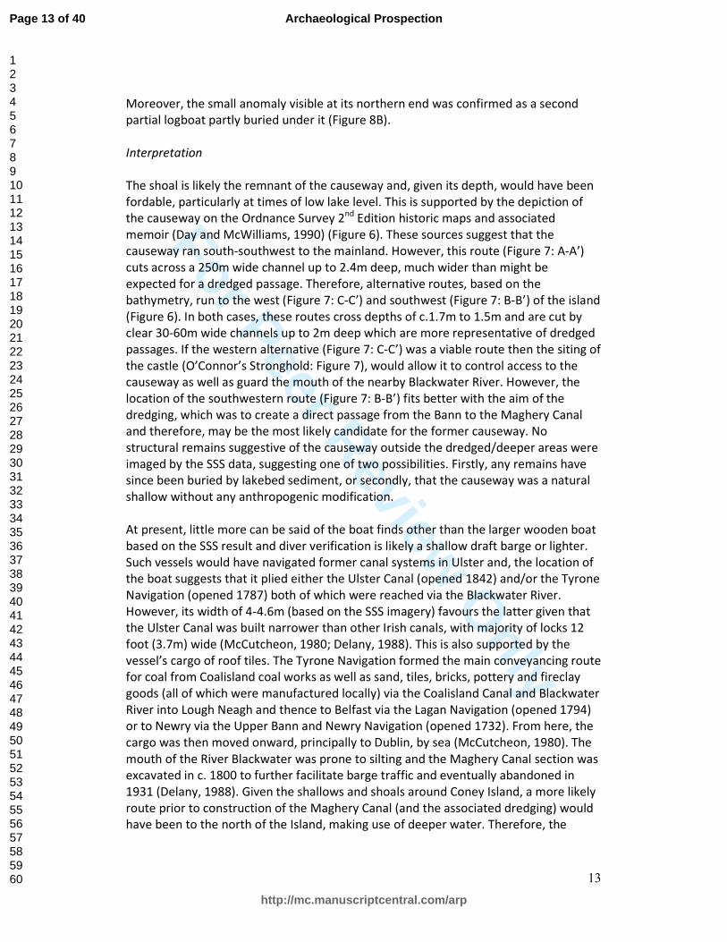
13
Moreover, the small anomaly visible at its northern end was confirmed as a second
partial logboat partly buried under it (Figure 8B).
Interpretation
The shoal is likely the remnant of the causeway and, given its depth, would have been
fordable, particularly at times of low lake level. This is supported by the depiction of
the causeway on the Ordnance Survey 2nd
Edition historic maps and associated
memoir (Day and McWilliams, 1990) (Figure 6). These sources suggest that the
causeway ran south-southwest to the mainland. However, this route (Figure 7: A-A’)
cuts across a 250m wide channel up to 2.4m deep, much wider than might be
expected for a dredged passage. Therefore, alternative routes, based on the
bathymetry, run to the west (Figure 7: C-C’) and southwest (Figure 7: B-B’) of the island
(Figure 6). In both cases, these routes cross depths of c.1.7m to 1.5m and are cut by
clear 30-60m wide channels up to 2m deep which are more representative of dredged
passages. If the western alternative (Figure 7: C-C’) was a viable route then the siting of
the castle (O’Connor’s Stronghold: Figure 7), would allow it to control access to the
causeway as well as guard the mouth of the nearby Blackwater River. However, the
location of the southwestern route (Figure 7: B-B’) fits better with the aim of the
dredging, which was to create a direct passage from the Bann to the Maghery Canal
and therefore, may be the most likely candidate for the former causeway. No
structural remains suggestive of the causeway outside the dredged/deeper areas were
imaged by the SSS data, suggesting one of two possibilities. Firstly, any remains have
since been buried by lakebed sediment, or secondly, that the causeway was a natural
shallow without any anthropogenic modification.
At present, little more can be said of the boat finds other than the larger wooden boat
based on the SSS result and diver verification is likely a shallow draft barge or lighter.
Such vessels would have navigated former canal systems in Ulster and, the location of
the boat suggests that it plied either the Ulster Canal (opened 1842) and/or the Tyrone
Navigation (opened 1787) both of which were reached via the Blackwater River.
However, its width of 4-4.6m (based on the SSS imagery) favours the latter given that
the Ulster Canal was built narrower than other Irish canals, with majority of locks 12
foot (3.7m) wide (McCutcheon, 1980; Delany, 1988). This is also supported by the
vessel’s cargo of roof tiles. The Tyrone Navigation formed the main conveyancing route
for coal from Coalisland coal works as well as sand, tiles, bricks, pottery and fireclay
goods (all of which were manufactured locally) via the Coalisland Canal and Blackwater
River into Lough Neagh and thence to Belfast via the Lagan Navigation (opened 1794)
or to Newry via the Upper Bann and Newry Navigation (opened 1732). From here, the
cargo was then moved onward, principally to Dublin, by sea (McCutcheon, 1980). The
mouth of the River Blackwater was prone to silting and the Maghery Canal section was
excavated in c. 1800 to further facilitate barge traffic and eventually abandoned in
1931 (Delany, 1988). Given the shallows and shoals around Coney Island, a more likely
route prior to construction of the Maghery Canal (and the associated dredging) would
have been to the north of the Island, making use of deeper water. Therefore, the
Page 13 of 40
http://mc.manuscriptcentral.com/arp
Archaeological Prospection
123456789101112131415161718192021222324252627282930313233343536373839404142434445464748495051525354555657585960

For Peer Review O
nly
14
position of the wreck to the south of the Island makes it more like that it was in use
and sank during the lifetime of the Maghery canal (c.1800-1931).
With the logboat finds, there is little in the way of chronological accuracy; no samples
were taken for dating, so their precise age remains to be confirmed. As previously
stated, logboats are not uncommon finds from Irish inland waterways, with as many as
560 recorded examples ranging in date from the Mesolithic to the Post-Medieval (K.
Brady pers. comm. 2016). For Lough Neagh specifically, not including the finds
described here, 30 logboats have been previously recorded ranging in age from the
Mesolithic (Brookend logboat: 5490-5246 BC) to the Medieval (Derryloughan boat 2:
1430-1620 AD) (Fry, 2000). Eleven of these logboats cluster in the southwest corner of
the Lough; two possibly from the Lough itself and others dredged from the Bann,
Blackwater or excavated from bogs (Lanting and Brindley, 1996; Fry, 2000; McNeary,
2010). Given the long occupation history of Coney Island (Addyman, 1965) and the
occurrence of similar boat finds in the locale, their presence at a river/lough
confluence is not to be unexpected.
Case study 3: Lacustrine Environment, Moorlough Lake
Site description
Survey was conducted within Moorlough Lake, a small inter-drumlin lake located in
County Fermanagh. The lake measures 950m by 300m across, representing an area of
c. 0.22km2. No information was available on the lake’s depth or substrate because it
had never been surveyed. Moorlough Lake is a typical example of the small lakes which
are a common feature of the drumlin belt of north-central Ireland. Many of these
contain known historic assets in the form of crannogs, and within Co. Fermanagh,
there appears to be a preference for crannogs to be located within small, relatively
isolated bodies of water (O’Sullivan, 1998; Neill, 2014). Despite this evidence of past
usage, these lakes are usually uncharted but their archaeological potential has been
reflected by the work of antiquarians in the late 1800s (Wakeman, 1870-1; Wakeman,
1872; Wood-Martin, 1886) and more recent archaeological study (Williams, 1993;
Foley and Williams, 2006; Bermingham et al., 2013). But despite past work on
Fermanagh crannogs, almost half (64) of the 142 recorded crannogs within the County
have not been positively identified and are listed only as probable crannogs. In the
case of Moorlough, a small circular island at its southern end is recorded in the
Northern Ireland Sites and Monuments Record (NI SMR) as a ‘probable’ crannog. This
assessment had been made on the basis that a small circular island was depicted on
the Ordnance Survey 1st
Edition map (though not on the 2nd
Edition). At the time of
survey, it had not been visited or subject to archaeological recording to verify this
assertion (FER 246:062: NI SMR, 2016).
Survey aim and methods
Moorlough Lake was chosen for survey as part of a wider pilot project which aimed to
Page 14 of 40
http://mc.manuscriptcentral.com/arp
Archaeological Prospection
123456789101112131415161718192021222324252627282930313233343536373839404142434445464748495051525354555657585960

For Peer Review O
nly
15
verify whether fully submerged, and hence unrecorded crannog remains, were present
within Co. Fermanagh’s small inter-drumlin lakes (Henry et al., 2014). Survey
concentrated primarily in the deeper portions of the lake where minor water level
fluctuations might not be expected to reveal fully submerged crannogs and secondarily
in the environs of the probable crannog at the southern end of the lake.
The primary aim of the survey was therefore to:
1) To identify if submerged crannog remains were present on the lakebed.
Secondary aims were:
2) To identify if any archaeological material was present on the lakebed; and,
3) To ground-truth potential archaeological remains by diving.
Parameters for the survey are summarized in Table 1. Tidal corrections were not
necessary as the lake is not tidal. All depths are therefore referenced to the lake level
on the day of survey
Results
Survey conducted over the lakebed found no evidence for any fully submerged
crannogs on the lakebed. Instead, the SBES data showed a flat or gently sloping
lakebed, with no anomalous mounds as might be expected if a crannog was present
(Figure 9). The SSS data also showed no indication of upstanding sub-circular features
or debris which might characterize a sunken crannog (e.g. Duck and McManus, 1987).
In fact, the majority of the lakebed was largely featureless, with 17 small anomalies
spread out across the lough with small clusters along the central part of the lake and
its north-eastern margin (Figure 9). These comprise various small (<2-3m across)
upstanding features or depressions which appear different to the natural acoustic
signature of the lake. The precise origins of the majority of the anomalies are unclear
as they were not subject to ground-truthing, and many are likely natural features such
as partly buried branches, tree trunks or boulders.
However, results from the environs of the small island were more encouraging. The
SSS data clearly delineated the northern perimeter of the island, showing it to be a
distinct circular mound with a diameter of c. total diameter of c. 35m versus the above
water diameter of 20m. The shallows around the southern, western and eastern edges
the island however, were choked with aquatic vegetation, which was difficult to
penetrate with either the SBES or SSS. The acquired data however, hint at the
continuation of the submerged circular perimeter. In addition, two closely spaced
vertical upstanding anomalies were imaged 35m north of the island’s shoreline and a
series of small low-lying anomalies can be seen on the western side of the island slope
(Figure 10).
Page 15 of 40
http://mc.manuscriptcentral.com/arp
Archaeological Prospection
123456789101112131415161718192021222324252627282930313233343536373839404142434445464748495051525354555657585960
For Peer Review O
nly
16
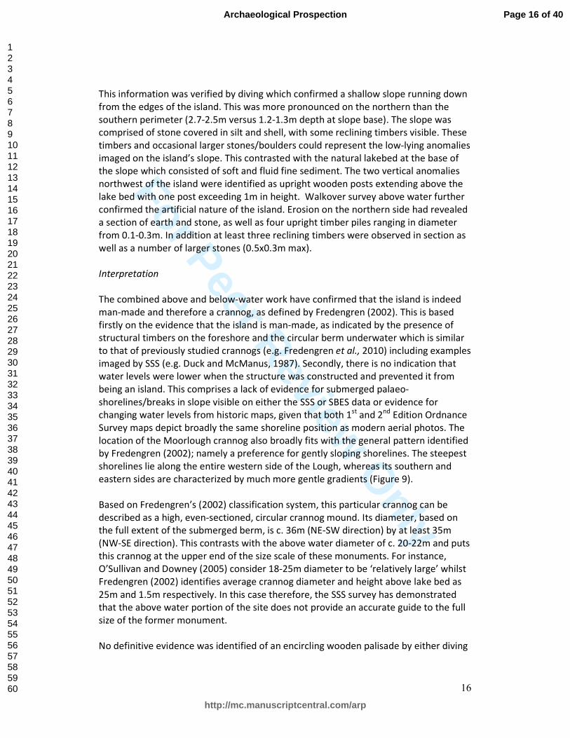
This information was verified by diving which confirmed a shallow slope running down
from the edges of the island. This was more pronounced on the northern than the
southern perimeter (2.7-2.5m versus 1.2-1.3m depth at slope base). The slope was
comprised of stone covered in silt and shell, with some reclining timbers visible. These
timbers and occasional larger stones/boulders could represent the low-lying anomalies
imaged on the island’s slope. This contrasted with the natural lakebed at the base of
the slope which consisted of soft and fluid fine sediment. The two vertical anomalies
northwest of the island were identified as upright wooden posts extending above the
lake bed with one post exceeding 1m in height. Walkover survey above water further
confirmed the artificial nature of the island. Erosion on the northern side had revealed
a section of earth and stone, as well as four upright timber piles ranging in diameter
from 0.1-0.3m. In addition at least three reclining timbers were observed in section as
well as a number of larger stones (0.5x0.3m max).
Interpretation
The combined above and below-water work have confirmed that the island is indeed
man-made and therefore a crannog, as defined by Fredengren (2002). This is based
firstly on the evidence that the island is man-made, as indicated by the presence of
structural timbers on the foreshore and the circular berm underwater which is similar
to that of previously studied crannogs (e.g. Fredengren et al., 2010) including examples
imaged by SSS (e.g. Duck and McManus, 1987). Secondly, there is no indication that
water levels were lower when the structure was constructed and prevented it from
being an island. This comprises a lack of evidence for submerged palaeo-
shorelines/breaks in slope visible on either the SSS or SBES data or evidence for
changing water levels from historic maps, given that both 1st
and 2nd
Edition Ordnance
Survey maps depict broadly the same shoreline position as modern aerial photos. The
location of the Moorlough crannog also broadly fits with the general pattern identified
by Fredengren (2002); namely a preference for gently sloping shorelines. The steepest
shorelines lie along the entire western side of the Lough, whereas its southern and
eastern sides are characterized by much more gentle gradients (Figure 9).
Based on Fredengren’s (2002) classification system, this particular crannog can be
described as a high, even-sectioned, circular crannog mound. Its diameter, based on
the full extent of the submerged berm, is c. 36m (NE-SW direction) by at least 35m
(NW-SE direction). This contrasts with the above water diameter of c. 20-22m and puts
this crannog at the upper end of the size scale of these monuments. For instance,
O’Sullivan and Downey (2005) consider 18-25m diameter to be ‘relatively large’ whilst
Fredengren (2002) identifies average crannog diameter and height above lake bed as
25m and 1.5m respectively. In this case therefore, the SSS survey has demonstrated
that the above water portion of the site does not provide an accurate guide to the full
size of the former monument.
No definitive evidence was identified of an encircling wooden palisade by either diving
Page 16 of 40
http://mc.manuscriptcentral.com/arp
Archaeological Prospection
123456789101112131415161718192021222324252627282930313233343536373839404142434445464748495051525354555657585960

For Peer Review O
nly
17
or the SSS. It possible that the stumps of the palisade have since been buried by the
lake mud, but it is equally possible that one was never built. Although crannogs by
definition were once required to have palisades (Lynn, 1983), more recent work has
shown that many crannogs did not have them or had partial rather than encircling
palisades (O’Sullivan, 1998; Fredengren, 2002). The purpose of the two isolated
wooden posts to the north of the crannog remains unclear. One possibility is that they
are remains of an outer palisade (see O’Sullivan and Downey 2005: Fig 2), but seems
odd that the remains of only two posts would survive both in close proximity and to a
significant length above the lakebed with no such remains evident elsewhere.
Similarly, there is no definitive evidence for a causeway linking the lakeshore and the
crannog. In this case, the area concerned was choked with weeds and vegetation
which hindered both acoustic survey and diver observations. Nevertheless, SBES data
indicate that water depth on the inside of the crannog rises gradually from c. 1.8m to
1.2m with the shallowest point directly between the crannog and the lakeshore, and
thus hinting at a possible route for a causeway, if one was present (Figure 10).
No samples were taken for dating, but based on the size and general shape of the
crannog (see Fredengren, 2002: Fig 20) there is a strong possibility that it dates to the
(early) Medieval period. If so, then it could be associated with the two raths (circular
earthwork enclosures) situated on high ground 600m west (FER246:044: NI SMR, 2016)
and 330m east (FER246:0045: NI SMR, 2016) of the crannog (Figure 9). Neither are
radiometrically dated or excavated, but along with the crannog, raths are regarded as
the characteristic sites of the Irish early Medieval, and thus the Moorlough crannog
could have provided a location for seasonal occupation or specialist activities for the
inhabitants of these raths.
Discussion
In each of the inland waterways discussed here, useful archaeological data was
obtained by remote sensing survey using a low-cost integrated SSS/SBES system. In all
instances, this setup was used to detect relatively small and low lying anomalies and,
for Coney Island and Moorlough Lake, these were subsequently ground-truthed as
features of genuine archaeological interest, specifically a sunken barge, two logboats
and wooden posts or timbers possibly associated with a crannog. The Moorlough data
was also useful in delineating the full extent of the crannog mound, showing it to be
much larger than appears above water. For Dunnalong, though ground-truthing has
yet to be undertaken, the positioning of the main debris scatter coupled with historic
accounts of the former settlement and/or quay structure suggest that some of the
material may be of archaeological interest. For all surveys, though the primary role of
the acquired bathymetry was to guide survey, in practice it provided added value in
giving a rationale for the positioning of the fort and ferry at Dunnalong and suggesting
possible former causeway routes for Coney Island and the Moorlough crannog.
Moreover, for all the case studies, the surveys conducted were the first to be done in
Page 17 of 40
http://mc.manuscriptcentral.com/arp
Archaeological Prospection
123456789101112131415161718192021222324252627282930313233343536373839404142434445464748495051525354555657585960

For Peer Review O
nly
18
these particular locations. All constitute areas which traditionally might be regarded
as difficult to survey or archaeologically unpromising as they are shallow, uncharted,
and in the case of Moorlough, have no formal boat access either by slip or waterway.
This has been overcome by use of the integrated SBES/SSS setup on a small shallow-
draft boat and demonstrated that such environments can be subject to effective
archaeological survey. Elsewhere, similar systems have been employed, for example in
Hungary, where they have been used for pre-dive prospection to great effect in the
Drava River (Toth, 2006; Toth, 2009) and Lough Corrib (Republic of Ireland) where
recent discoveries of multiple logboats were made off the back of a mapping project to
make hydrographic charts for anglers (Brady, 2014a; 2014b; Northage, 2016). These
recent projects supplement previous demonstrations using more conventional setups
(e.g. Duck and McManus, 1987; Sonnenburg and Boyce, 2008).
While results here are encouraging and demonstrate the usefulness of the low-cost
system, there are, however, some performance issues to be considered. One concerns
the image quality of the SSS, which itself is partly controlled by its resolving power.
Range to target and beam angle are particularly important for transverse (also referred
to as along-track) resolution: the ability of the system to distinguish between two
objects parallel to the line of travel and the primary determinant of image quality (Key,
2000; Quinn et al., 2005). Small beam angles create narrower beams and hence offer
greater resolving power. In general, narrow beams are produced by longer transceiver
arrays and higher frequencies (Key, 2000; Edgetech, 2005). Given that beam angle is
dependent on transceiver array length, the fact that the LSS-1 has a short transceiver
(17.3cm) suggests it has a wide beam angle and hence lower resolving power.
Moreover, since beams naturally spread away from the transceiver, the effective
transverse resolution is also controlled by the range to the target. Consequently,
distant targets will not be imaged to the same resolution as nearby targets.
These factors appear to be borne out by our experience of surveying with this system.
In general, image quality decreases with swath width such that optimal range for
object detection is <30m and with the best imagery collected with the target within c.
15m of the transceiver. This is illustrated in Figure 11 which shows wreckage and
associated debris imaged during a survey of the Foyle Bridge area (River Foyle; see
Figure 1 for location). Based on discussion with the harbourmaster, this wreckage
probably represents the base of a former navigation beacon. Other man-made objects
are also present immediately adjacent to the wreckage including at least two circular
objects interpreted as car tyres and, to the west, a rectangular patch of smaller
upstanding objects, possibly representing pile bases. In this case, the nature of this
survey (confirmation of an anomaly originally reported during a search and recovery
operation for a missing person: see Westley, 2012) meant that the same piece of
wreckage was imaged on multiple passes at a distance of 5-10 m from the transceivers,
but at different ranges and frequencies. Thus Figure 11A and 11B show the difference
between 800kHz and 455khz settings at 30m range, while 11B and 11C compare
455kHz but at ranges of 30m and 60m. From these it is clear that the LSS-1 is capable
of detecting the wreckage as a man-made anomaly at close ranges (<15m) and both
Page 18 of 40
http://mc.manuscriptcentral.com/arp
Archaeological Prospection
123456789101112131415161718192021222324252627282930313233343536373839404142434445464748495051525354555657585960

For Peer Review O
nly
19
frequencies. This is true even with the LSS-1’s lower resolution (455 kHz) mode (Figure
11B). However, the tyres and pilings immediately adjacent to the wreckage are no
longer discernible, though another tyre c. 20m south of the wreckage is identifiable.
Performance worsens as swath width increases. This is illustrated in Figure 11C which
shows the same wreckage, again imaged at 455 kHz but using a larger range (60m).
Even though the wreckage is located c. 10m from the transceivers it shows up only as a
faint anomaly with no discernible structure. Therefore, this shows that there are
limitations to the imaging ability of the low-cost system, and that the choice of
frequency and range are particularly important in its ability to detect small objects,
such as archaeological assets often are.
In addition, the low-cost setup as used here has three disadvantages. Firstly, the
inability to raise/lower the transceivers with changing water depth which, in our
experience, makes the low-cost system less effective when water depth increases
beyond c. 20m. Either the water column takes up most of the data, or if compensated
for by increasing the range, resolution decreases and small anomalies become harder
to see. Further, since acoustic shadows can play a major role in object identification
(Bates et al., 2011), it can be important to maximize these by dropping the towfish to a
minimum height above seabed. This is simply not possible with the current set up of
hull-mounted transceivers. Secondly, a fixed mounting means that the transceivers are
more sensitive to survey vessel motion compared to a towed setup in which the tow
cable damps some of the motion. Consequently, when conditions are less than
optimal, for instance with waves and strong currents, the resulting data often contain
numerous distortions from heave and course corrections. Thirdly, noise in the data is
also a factor, due to the proximity to the survey vessels’ engines compared to a towed
system. However, this tends to only affect one channel (that closest to the engines)
and can be mitigated by surveying at sufficiently low speed (<3-4kts), increasing the
distance between the transceiver and engine or almost completely eliminated by using
an electric engine.
That said, all the above disadvantages are mitigated in shallow confined inland
waterways. The limited swath width and depth range is compensated for by the
generally small areal extent and depth of the target waterbodies. They also tend to be
calmer than offshore environments, hence reducing distortions caused by survey
vessel motion. This in turn means that less powerful engines (including quiet electric
motors) are feasible which has the effect of reducing noise in the data even when the
transducers are transom-mounted. Consequently, the setup described here is best-
suited for shallow, restricted inland waterways. Hull- or pole-mounting the small
transceivers also reduces the potential for snagging or impacting the river/lakebed and
allows tight manoeuvring, which is often necessary in these restricted waterways. The
small size of the integrated topside unit is also an advantage, particularly when using
the requisite small and shallow draft boats. In short, the combination of a small
integrated SBES and SSS in an easily portable package allows the logistical challenges
of surveying confined waterways described in the introduction to be easily overcome.
Page 19 of 40
http://mc.manuscriptcentral.com/arp
Archaeological Prospection
123456789101112131415161718192021222324252627282930313233343536373839404142434445464748495051525354555657585960

For Peer Review O
nly
20
This is not to say that conventional SSS and SBES systems are not effective in these
environments. On the contrary, relatively portable survey-grade systems are available
which can be pole-mounted and it would be desirable to have the improved accuracy,
image quality and range which comes with such a system. Unfortunately, the reality is
that as equipment improves, so too does the price and consequently, their use may be
unaffordable to projects or organizations which are on a tight budget. This may be
particularly true of inland waterways, given their comparative lack of attention
compared to offshore and marine environments. In these situations, as demonstrated
here, and provided that its limitations are understood and accounted for, the low cost
system can be an adequate substitute capable of acquiring data that are sufficient for
archaeological purposes.
Conclusion
In the case studies presented here, a series of shallow confined inland waterways have
been subject to effective archaeological survey using a low-cost integrated SSS/SBES
system. This has allowed potential insights into the location of former structures and
the identification of archaeological anomalies for follow up ground-truthing. In these
cases, the low-cost system has proved a useful addition to the archaeological toolkit.
Although these system should not be seen as a direct replacement for survey-grade
systems owing to limitations in their useful depth and range of operation and reduced
image quality, they do perform well in shallow, confined waterways where their
disadvantages are minimized. Under such conditions, image quality and their object
detection ability is sufficient for archaeological purposes and they can be considered to
be an acceptable substitute for more expensive survey-grade systems. The traditional
difficulty of surveying low visibility, shallow, restricted and inaccessible waterways
means that they may hold a great deal of unrecorded or poorly-documented material.
Geophysical approaches, such as discussed here, are one means by which to open up
the possibility of effective survey of these submerged heritage assets and offer
opportunities for improved mitigation in development contexts; record enhancement
and new underwater archaeological research.
Acknowledgements
All survey work presented here was supported by the Northern Ireland Environment
Agency; we thank our colleagues there, notably Rhonda Robinson, Paul Logue and
Claire Foley. All historic maps were supplied by Land and Property Services under the
Northern Ireland Mapping Agreement. Survey and ground-truthing would not have
been possible without assistance from colleagues at Ulster University, in particular,
Colin Breen, Wes Forsythe, Sandra Henry and Chris McGonigle. Special thanks to Rory
Quinn for his insightful comments on the manuscript and knowledge of all things
sidescan-related and Nigel Macauley for applying his workshop savvy in the
construction of the various deployment rigs.
Page 20 of 40
http://mc.manuscriptcentral.com/arp
Archaeological Prospection
123456789101112131415161718192021222324252627282930313233343536373839404142434445464748495051525354555657585960

For Peer Review O
nly
21
References
Addyman P. 1965. Coney Island, Lough Neagh: Prehistoric settlement, Anglo-Norman
castle and Elizabethan native fortress: An interim report on excavations in 1962 to
1964. Ulster Journal of Archaeology 28: 78-101.
Bates CR, Lawrence M, Dean M, Robertson P. 2011. Geophysical methods for wreck-
site monitoring: the Rapid Archaeological Site Surveying and Evaluation (RASSE)
programme. International Journal of Nautical Archaeology 40(2): 404-416.
Bates CR, Fenning P. 2013. An adaptable survey A-platform for shallow water. Hydro
International. (http://www.hydro-international.com/content/article/an-adaptable-
survey-platform-for-shallow-water). Last accessed May 2016.
Bates MR, Nayling N, Bates CR, Dawson S, Huws D, Wickham-Jones C. 2013. A multi-
disciplinary approach to the archaeological investigation of a bedrock-dominated
shallow-marine landscape: an example from the Bay of Firth, Orkney, UK. International
Journal of Maritime Archaeology 42: 24-43.
Bermingham N, Moore C, O’Keeffe J, Gormley M. 2013. Drumclay: a most surprising
crannog. Archaeology Ireland 27(2): 37-40.
Boland D. 1994. Underwater Archaeology in Ireland. Archaeology Ireland 8(3): 13-14.
Boland D, O’Sullivan. A. 1997. An early medieval wooden bridge at Clonmacnoise. In
The Quaternary of the Irish Midlands, Mitchell F, Delaney C (eds), Field Guide 21. Irish
Association for Quaternary Studies: Dublin; 14-21.
Bourke C. 1998. Fine Metalwork from the River Blackwater. Archaeology Ireland 12(3):
30-31.
Bourke L. 2001. Crossing the Rubicon: Bronze Age Metalwork from Irish Rivers. National
University of Ireland, Galway: Galway.
Bradley J. 1991. Excavations at Moynagh Lough, Co. Meath. Journal of the Royal
Society of Antiquaries of Ireland 111: 5-26
Brady N. 2000. John’s Bridge, River Nore, Kilkenny (2000:0538). Excavations.ie online
database of Irish Excavation reports.
(http://www.excavations.ie/report/2000/Kilkenny/0005363/). Last accessed May 2016
Brady N. 2001. John’s Bridge, River Nore, Kilkenny (2001:704). Excavations.ie online
database of Irish Excavation reports.
(http://www.excavations.ie/report/2001/Kilkenny/0006642/). Last accessed May 2016
Page 21 of 40
http://mc.manuscriptcentral.com/arp
Archaeological Prospection
123456789101112131415161718192021222324252627282930313233343536373839404142434445464748495051525354555657585960

For Peer Review O
nly
22
Brady K. 2014a. The logboats in the lake. Current Archaeology 292: 10-15.
Brady K. 2014b. Secrets of the lake: the Lough Corrib logboats. Archaeology Ireland
28(4): 34-38.
Brown A. 1997. Alluvial Geoarchaeology. Floodplain Archaeology and Environmental
Change. Cambridge University Press: Cambridge.
Cantelas F, Rodgers B. The Maple Leaf: a case study in cost-effective zero-visibility
riverine archaeology. International Journal of Nautical Archaeology 23: 271-282.
Cassen S, Baltzer A, Lorin A, Fournier J, Sellier D. 2011. Submarine Neolithic Stone
Rows near Carnac (Morbihan), France: preliminary results from acoustic and
underwater survey. In Submerged Prehistory, Benjamin J, Bonsall C, Pickard C, Fischer
A. (eds). Oxbow: Oxford; 99-110.
Coles J. 1984. The archaeology of wetlands. Edinburgh University Press: Edinburgh.
Coles J, Coles B. 1989. People of the wetlands. Bogs, bodies and lake-dwellers. Thames
and Hudson: London.
Coles J, Lawson A. 1987. European wetlands in prehistory. Oxford University Press:
Oxford.
Collins A. 1955. Excavations at Lough Faughan crannog, Co. Down, 1950-51. Ulster
Journal of Archaeology 22: 92-101
Condit T, O’Sullivan A. 1999. Landscapes of movement and control: interpreting
prehistoric hillforts and fording-places on the River Shannon. Discovery Programme
Reports 5: 25-39.
Conneller C, Milner N, Taylor B, Taylor M. 2012. Substantial settlement in the European
Early Mesolithic: new research at Star Carr. Antiquity 86: 1004-1020.
Croes D, Fagan J, Zehendner M. 2009. Sunken Village, Sauvie Island, Oregon, USA: A
Report on the 2006–2007 Investigations of National Historic Landmark Wet Site
35MU4. Journal of Wetland Archaeology 9: 1-215.
Day A, McWilliams P. 1990. Ordnance Survey Memoirs of Ireland. Parishes of County
Armagh 1835-8. Institute of Irish Studies: Belfast.
Delany R. 1988. A Celebration of 250 years of Ireland’s Inland Waterways. Appletree
Press: Belfast.
Duck R, McManus K. 1987. Sidescan sonar applications in limnoarchaeology.
Page 22 of 40
http://mc.manuscriptcentral.com/arp
Archaeological Prospection
123456789101112131415161718192021222324252627282930313233343536373839404142434445464748495051525354555657585960

For Peer Review O
nly
23
Geoarchaeology: An International Journal 2: 223-230.
Edgetech. 2005. Application note: Sidescan sonar beamwidth.
(http://www.edgetech.com/pdfs/ut/app_note_beamwidth.pdf). last accessed May
2015.
Farrell R, Buckley V. 1984. Preliminary examination of the potential of offshore and
underwater sites in Loughs Ennell and Analla, Co. Westmeath, Ireland. International
Journal of Nautical Archaeology 13: 281-285.
Farrell R. 1989. The Crannog Archaeological Project (CAP), Republic of Ireland II: Lough
Lene – offshore island survey. International Journal of Nautical Archaeology 18: 221-
228.
Farrell R, Kelly E, Gowan M. 1989. The Crannog Archaeological Project (CAP), Republic
of Ireland: a pre-preliminary report. International Journal of Nautical Archaeology 18:
123-136.
Firth A. 2011. Marine Geophysics: integrated approaches to sensing the seabed. In
Remote Sensing for Archaeological Heritage Management. Proceedings of the 11th
EAC
Heritage Management Symposium, Cowley D (ed). EAC Occasional Paper 5. EAC:
Brussels; 129-142.
Firth A, Callan N, Scott G, Gane T, Arnott S. 2012. London Gateway. Maritime
Archaeology in the Thames Estuary. Wessex Archaeology Report No. 30. Wessex
Archaeology: Salisbury.
Firth A. 2014. Heritage Assets in Inland Waters. Report Prepared for English Heritage.
Fjordr Ltd: Salisbury.
Foley C, William B. 2006. The Crannogs of County Fermanagh. In The Modern Traveller
to Our Past: Festschrift in Honour of Ann Hamlin, Meek M (ed). Colourbooks: Dublin;
53-64.
Fredengren C. 2002. Crannogs. Wordwell: Bray
Fredengren C, Kilfeather A, Stuijts I. 2010. Lough Kinale: studies of an Irish lake.
Discovery Program Monograph 8. Wordwell: Dublin.
Fry M. 2000. Coiti: Logboats from Northern Ireland. Greystone Press: Antrim.
Gaffney V, Thomson K, Fitch S (eds). 2007. Mapping Doggerland: The Mesolithic
Landscapes of the Southern North Sea. Archaeopress: Oxford.
Hare R. 2008. Small boat surveys in shallow water. In Marine Habitat Mapping
Page 23 of 40
http://mc.manuscriptcentral.com/arp
Archaeological Prospection
123456789101112131415161718192021222324252627282930313233343536373839404142434445464748495051525354555657585960

For Peer Review O
nly
24
Technology for Alaska, Reynolds J, Green H (eds) Alaska Sea Grant for North Pacific
Research Board: Fairbanks; 71-89.
Hamel A. 2011 Wrecks at Sea: Marine ALSF Research in Context. Marine ALSF Science
Monograph Series No. 6. Marine Aggregates Levy Sustainability Fund.
Hencken H. 1950. Lagore crannog: an Irish royal residence of the seventh to tenth
century A.D. Proceedings of the Royal Irish Academy 53C: 1-248.
Henderson J. 1998. A survey of crannogs on the Lake of Menteith, Stirlingshire.
Proceedings of the Society of Antiquaries of Scotland 128: 273-292.
Henry S, Westley K, Forsythe W. 2014. Fermanagh Crannog Identification Project.
Report prepared for the Northern Ireland Environment Agency: Historic Environment
Division. pp. 49.
Howard A, Challis K, Holden J, Kincey M, Passmore D. 2008. The impact of climate
change on archaeological resources in Britain: a catchment scale assessment. Climatic
Change 91: 405-422.
Howard A, Knight D, Coulthard T, Hudson-Edwards K, Kossoff D, Malone S. (in press).
Assessing riverine threats to heritage assets posed by future climate change through a
geomorphological approach and predictive modelling in the Derwent Valley Mills WHS,
UK. Journal of Cultural Heritage
Hunter R. 2011. Strabane Barony during the Ulster Plantation 1607-1641. Ulster
Historical Foundation: Belfast.
Kaeser A, Litts T, Tracy T. 2013. Using low-cost side-scan sonar for benthic mapping
throughout the lower Flint River, Georgia, USA. River Research and Applications 29:
634-644.
Keane M. 1995. Lough More, Co. Mayo: the crannog. Irish Archaeological Wetland Unit
Transactions 4: 167-182
Kelly E. 1993. Investigation of ancient fords on the River Suck. Inland Waterways 20: 4-
5.
Key W. 2000. Side scan sonar technology. OCEANS 2000 MTS/IEEE Conference and
Exhibition 2: 1029-1033.
Lafferty B, Quinn R, Breen C. 2006. A side-scan sonar and high-resolution Chirp sub-
bottom profile study of the natural and anthropogenic sedimentary record of Lower
Lough Erne, northwestern Ireland. Journal of Archaeological Science 33(6): 756-766.
Page 24 of 40
http://mc.manuscriptcentral.com/arp
Archaeological Prospection
123456789101112131415161718192021222324252627282930313233343536373839404142434445464748495051525354555657585960

For Peer Review O
nly
25
Lavelle D. 1992. The Lough Carra causeway, Ireland. NewsWARP 11: 13-15.
Lanting J, Brindley A. 1996. Irish Logboats and Their European Context. Journal of Irish
Archaeology 7: 85-95.
Logue P, McHugh R. 2013. The 2012 Excavation. In: The Lost Settlement of Dunnalong.
Guildhall Press: Derry; 51-60.
Lübke H, Schmölckem U, Tauber F. 2011. Mesolithic hunter-fishers in a changing world:
a case study of submerged sites on the Jäckelberg, Wismar Bay, northeastern
Germany. In Submerged Prehistory, Benjamin J, Bonsall C, Pickard C, Fischer A. (eds).
Oxbow: Oxford; 21-37.
Lynn C. 1983. Some ‘early’ ring-forts and crannogs. Journal of Irish Archaeology 1: 47–
58.
Malim T, Morgan D, Panter I. 2015. Suspended preservation: Particular preservation
conditions within the Must Farm - Flag Fen Bronze Age landscape. Quaternary
International 368: 19-30.
McCutcheon W. 1980. The Industrial Archaeology of Northern Ireland. HMSO: Belfast.
McHugh R. 2013. The geophysical survey of Dunnalong fort. In: The Lost Settlement of
Dunnalong. Guildhall Press: Derry; 46-50.
McKenna J, Quinn R, Donnelly D, Cooper JAG. 2008. Accurate Mental Maps as an
Aspect of Local Ecological Knowledge (LEK): a Case Study from Lough Neagh, Northern
Ireland. Ecology and Society 13(1): 1-23.
McNeary R, Bourke L. 2009. Freshwater archaeology in Northern Ireland. Archaeology
Ireland 23(2): 38-39.
McNeary R. 2010. Freshwater Archaeology in Northern Ireland: summary strategy
document for rivers. Report prepared for the Northern Ireland Environment Agency:
Built Heritage Division. 146pp.
McNeary R. 2011. Riverine Archaeology in Northern Ireland: an evaluation.
International Journal of Nautical Archaeology 40(1): 162-170.
McNeary R. 2012a. Underwater Investigations at Dunnalong Fort 2012. Unpublished
report prepared for the Northern Ireland Environment Agency, Dept. of the
Environment. 32pp.
McNeary R. 2012b. Underwater Investigations at Rindoon 2012. Unpublished report
prepared for St. John’s Parish Heritage Group and the Royal Irish Academy. 60pp.
Page 25 of 40
http://mc.manuscriptcentral.com/arp
Archaeological Prospection
123456789101112131415161718192021222324252627282930313233343536373839404142434445464748495051525354555657585960

For Peer Review O
nly
26
McNeary R. 2013. Maritime Archaeology and the river. In: The Lost Settlement of
Dunnalong. Guildhall Press: Derry; 36-41.
McNeary R, Campbell L, O’Keeffe J, Robinson R. 2013. Beyond the gloom. Archaeology
Ireland 27(1): 37-39.
Menotti F. 2012. Wetland archaeology and beyond: theory and practice. Oxford
University Press: Oxford.
Menotti F, O’Sullivan A. (eds). 2013. The Oxford Handbook of Wetland Archaeology.
Oxford University Press: Oxford.
Moore F. 1996. Ireland's Oldest Bridge: At Clonmacnoise. Archaeology Ireland 10(4):
24-27.
Neill K. 2014. Early Christian Secular Monuments. In An Archaeological Survey of
County Fermanagh: Volume 1, Part 2: Early Christian and Medieval Periods, Foley C,
McHugh R (eds). Northern Ireland Environment Agency: Belfast; 305-327.
NI SMR. 2016. Northern Ireland Sites and Monuments Record.
(http://apps.ehsni.gov.uk/ambit/ ). Last accessed May 2016.
Northage T. 2016. Fishing and cruising charts for Lough Corrib and lakes in the west of
Ireland.( http://www.anglingcharts.com/). Last accessed May 2016.
O’Connor N. 1989. Underwater Archaeology. Archaeology Ireland 3(1): 26-29.
O’Sullivan A. 1998. The Archaeology of Lake Settlement in Ireland. Discovery
Programme Monograph 4. Royal Irish Academy. Dublin.
O’Sullivan A. 2007. Exploring past people's interactions with wetland environments in
Ireland. Proceedings of the Royal Irish Academy 107C: 147-203
O’Sullivan A, Sands R, Kelly E. 2007. Coolure Demesne crannog, Lough Derravaragh: an
introduction to its archaeology and landscapes. Wordwell: Bray.
O’Sullivan M, Downey L. 2005. Crannogs. Archaeology Ireland 19(4): 34-36.
Palomo A, Piqué R, Terradas X, Bosch A, Buxó R, Chinchilla J, Saña M, Tarrús J. 2014.
Prehistoric cccupation of Banyoles lakeshore: results of recent excavations at La Draga
site, Girona, Spain. Journal of Wetland Archaeology 14: 58-73.
Papatheodorou G, Geraga M, Ferentinos G. 2005. The Navarino naval battle site,
Greece – an integrated remote-sensing survey and rational management approach.
Page 26 of 40
http://mc.manuscriptcentral.com/arp
Archaeological Prospection
123456789101112131415161718192021222324252627282930313233343536373839404142434445464748495051525354555657585960

For Peer Review O
nly
27
International Journal of Nautical Archaeology 34(1): 95-109.
Parker R, Ruffell A, Hughes D, Pringle J. 2010. Geophysics and the search of freshwater
bodies: A review. Science and Justice 50: 141-149.
Plets R, Dix J, Adams J, Bull J, Henstock T, Gutowski M, Best A. 2009. The use of a high-
resolution 3D Chirp sub-bottom profiler for the reconstruction of the shallow water
archaeological site of the Grace Dieu (1439), River Hamble, UK. Journal of
Archaeological Science 36(2): 408-418
Plets R, Quinn R, Forsythe W, Westley K, Bell T, Benetti S, McGrath F, Robinson R.
2011. Using Multibeam Echo-Sounder Data to Identify Shipwreck Sites: archaeological
assessment of the Joint Irish Bathymetric Survey data. International Journal of Nautical
Archaeology 40(1): 87-98.
Plets R. 2013. Underwater survey and acoustic detection and characterization of
archaeological materials. In The Oxford Handbook of Wetland Archaeology, Menotti F,
O’Sullivan A. (eds). Oxford University Press: Oxford; 433-449.
Ryan M. 1980. An early Mesolithic site in the Irish midlands. Antiquity 80: 46-47.
Quinn R, Breen C, Forsythe W, Barton K, Rooney S, O'Hara D. 2002. Integrated
geophysical surveys of the French frigate La-Surveillante (1797), Bantry Bay, Co. Cork,
Ireland. Journal of Archaeological Science 29(4): 413-422.
Quinn R, Dean M, Lawrence M, Liscoe S, Boland D. 2005. Backscatter responses and
resolution considerations in archaeological side-scan sonar surveys: a control
experiment. Journal of Archaeological Science 32(8): 1252-1264.
Quinn R. 2007. The assimilation of marine geophysical data into the maritime sites and
monuments record, Northern Ireland. Historical Archaeology 41(3): 9-24.
Quinn R. 2011. Acoustic Remote Sensing in Maritime Archaeology. In The Oxford
Handbook of Maritime Archaeology. Catsambis A, Ford B, Hamilton DL (eds). Oxford
University Press: Oxford; 68-89.
Raftery B. 1982. Two recently discovered shields from the Shannon Basin. Journal of
the Royal Society of Antiquaries of Ireland 112: 5-17.
Rönnby J. 1990. New research at Bulverket Lake Building, Gotland, Sweden.
International Journal of Nautical Archaeology 19(3): 233-237.
Roulston W. 2010. Three centuries of life in a Tyrone parish: a history of Donagheady
from 1600 to 1900. Strabane Historical Society: Letterkenny.
Page 27 of 40
http://mc.manuscriptcentral.com/arp
Archaeological Prospection
123456789101112131415161718192021222324252627282930313233343536373839404142434445464748495051525354555657585960

For Peer Review O
nly
28
Roulston W. 2013. Fort of the ships: Dunnalong through the ages. In: The Lost
Settlement of Dunnalong. Guildhall Press: Derry; 10-19.
Stickel E, Garrison E. 1988. New applications of remote sensing: geophysical
prospection for underwater archaeological sites in Switzerland. In Wet Site
Archaeology, Purdy B (ed.). Telford Press: New Jersey; 69-87.
Sonnenburg E, Boyce J. 2008. Data-fused digital bathymetry and side-scan sonar as a
base for archaeological inventory of submerged landscapes in the Rideau Canal,
Ontario, Canada. Geoarchaeology: An International Journal 23(5): 654-674.
Tóth A. 2006. River archaeology—a new field of research. Archeometriai Mühely 1: 61–
66.
Tóth A. 2009. La Drava (Hongrie). Un fleuve inconnu. Dossiers d’Archaeologie 331: 46-
49.
UK Lakes Portal. 2016. Lough Neagh.
(https://eip.ceh.ac.uk/apps/lakes/detail.html#wbid=50001). Last accessed April 2016.
Wakeman W. 1870-1. Remarks upon three hitherto unnoticed crannogs in Drumgay
Lake, near Enniskillen. Journal of the Royal Society of Antiquaries of Ireland 11: 232-
235.
Wakeman W. 1872. Observations on the principal crannogs of Fermanagh. Journal of
the Royal Society of Antiquaries of Ireland (4th
series) 2: 216.
Wallace J. 1917. A Find of Oak Dug-Outs. Journal of the Royal Society of Antiquaries of
Ireland 7(1): 85-86.
Westley K. 2012. ‘Foyle anomaly’ survey report. Unpublished report prepared for the
Northern Ireland Environment Agency, Dept. of the Environment. 22pp.
Westley K, Plets R, Quinn R. 2014. Holocene palaeo-geographic reconstructions of the
Ramore Head area, Northern Ireland, using geophysical and geotechnical data: palaeo-
landscape mapping and archaeological implications, Geoarchaeology: An International
Journal 29: 411-430.
Wood-Martin W. 1886. The lake dwellings of Ireland or ancient lacustrine habitations
or Erin commonly called crannogs. Dublin.
Woodman P. 2015. Ireland’s First Settlers: Time and the Mesolithic. Oxbow: Oxford.
Page 28 of 40
http://mc.manuscriptcentral.com/arp
Archaeological Prospection
123456789101112131415161718192021222324252627282930313233343536373839404142434445464748495051525354555657585960

For Peer Review Only
29
Tables
Table 1. Summary table showing survey parameters for each of the case studies discussed in this paper
Date Line
Spacing
(m)
Frequency
(kHz)
Range
(m)
Overall
trackline
length
(km)
Aim
Dunnalong 1 25/07/2012 20m 455 25m 27.6km Primary: bathymetry of the fort/settlement
environs
Secondary: anomaly detection
Dunnalong 2 08/08/2012 20m 455, 800 20-25m 5.7km Focus on the southern pool for anomaly
detection
Coney Island 1 22/08/2013 25m 455 30m 12.1km Primary: bathymetry of Coney Island
environs
Secondary: anomaly detection
Coney Island 2 29/08/2013 10-20m 455, 800 12-30m 8.9km Focus on high potential anomalies
Moorlough
Lake
24/06/2014 20-30m 455, 800 18-25m 7.9km Primary: identify potential crannog remains
Secondary: anomaly detection
Page 29 of 40
http://mc.manuscriptcentral.com/arp
Archaeological Prospection
123456789101112131415161718192021222324252627282930313233343536373839404142434445464748495051525354555657585960
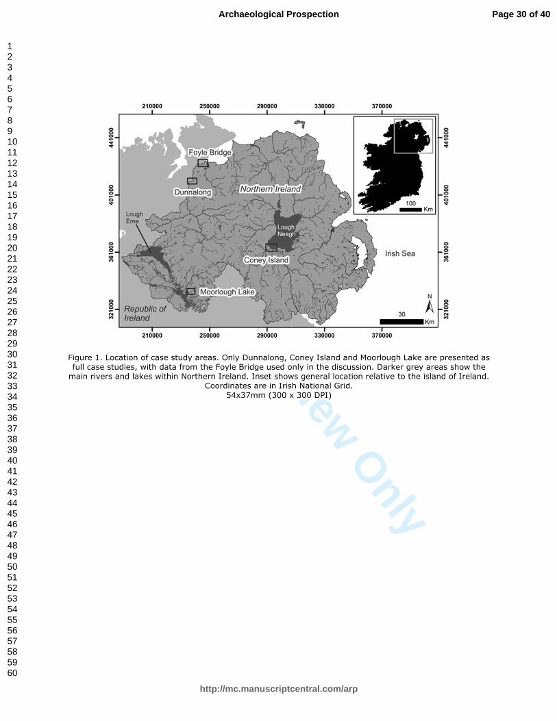
For Peer Review O
nly
Figure 1. Location of case study areas. Only Dunnalong, Coney Island and Moorlough Lake are presented as full case studies, with data from the Foyle Bridge used only in the discussion. Darker grey areas show the main rivers and lakes within Northern Ireland. Inset shows general location relative to the island of Ireland.
Coordinates are in Irish National Grid. 54x37mm (300 x 300 DPI)
Page 30 of 40
http://mc.manuscriptcentral.com/arp
Archaeological Prospection
123456789101112131415161718192021222324252627282930313233343536373839404142434445464748495051525354555657585960
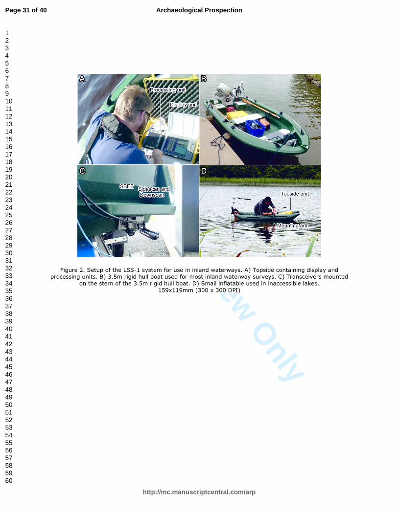
For Peer Review O
nly
Figure 2. Setup of the LSS-1 system for use in inland waterways. A) Topside containing display and processing units. B) 3.5m rigid hull boat used for most inland waterway surveys. C) Transceivers mounted
on the stern of the 3.5m rigid hull boat. D) Small inflatable used in inaccessible lakes.
159x119mm (300 x 300 DPI)
Page 31 of 40
http://mc.manuscriptcentral.com/arp
Archaeological Prospection
123456789101112131415161718192021222324252627282930313233343536373839404142434445464748495051525354555657585960

For Peer Review O
nly
Figure 3. Bathymetric map generated from Phase 1 SBES data for the riverbed off Dunnalong superimposed onto a georeferenced Second Edition (1850-55) Ordnance Survey historic map. Note the location of the fort, ferry and causeways in relation to the deeper pools directly in front of them. Profiles A-A’ and B-B’ are from
individual SBES lines which cross the submerged tips of the causeways and accordingly show a distinct 0.5-0.6m high peak. Also shown are individual anomalies or anomaly clusters identified from the SSS from both
Phases 1 and 2. 203x209mm (300 x 300 DPI)
Page 32 of 40
http://mc.manuscriptcentral.com/arp
Archaeological Prospection
123456789101112131415161718192021222324252627282930313233343536373839404142434445464748495051525354555657585960
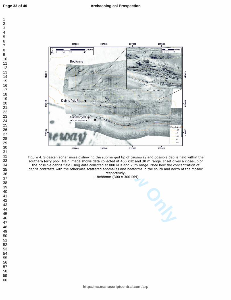
For Peer Review O
nly
Figure 4. Sidescan sonar mosaic showing the submerged tip of causeway and possible debris field within the southern ferry pool. Main image shows data collected at 455 kHz and 30 m range. Inset gives a close-up of the possible debris field using data collected at 800 kHz and 20m range. Note how the concentration of
debris contrasts with the otherwise scattered anomalies and bedforms in the south and north of the mosaic respectively.
118x88mm (300 x 300 DPI)
Page 33 of 40
http://mc.manuscriptcentral.com/arp
Archaeological Prospection
123456789101112131415161718192021222324252627282930313233343536373839404142434445464748495051525354555657585960
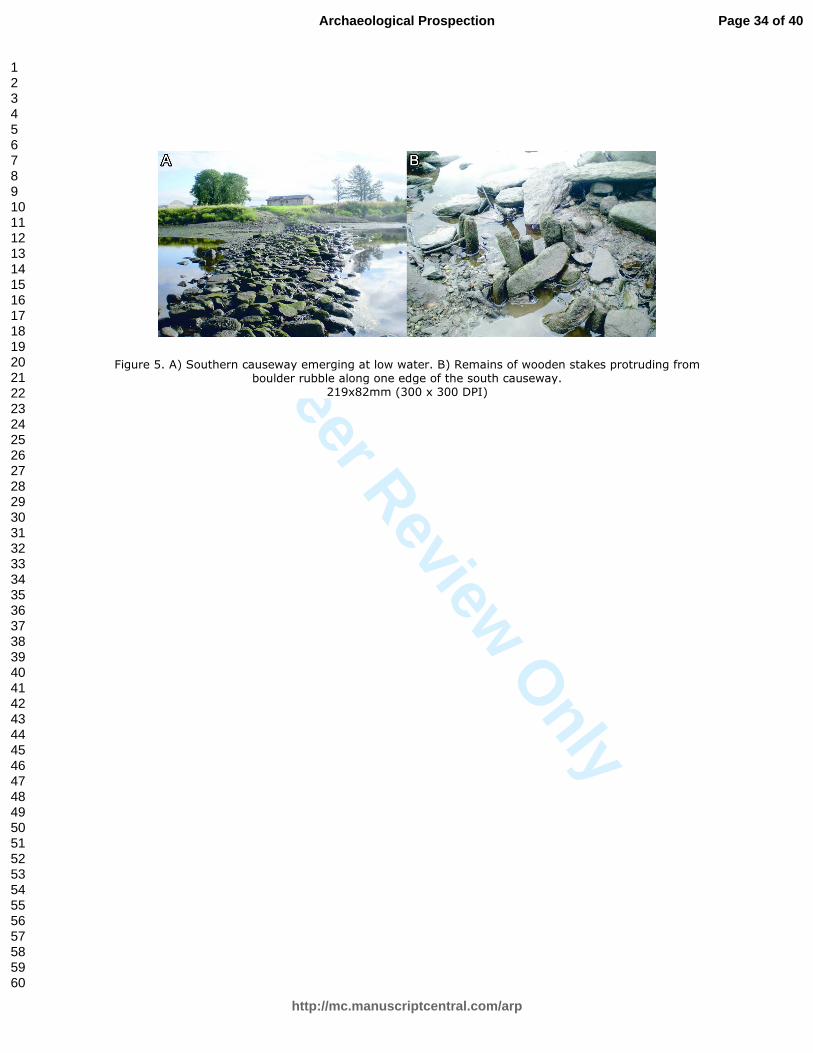
For Peer Review O
nly
Figure 5. A) Southern causeway emerging at low water. B) Remains of wooden stakes protruding from boulder rubble along one edge of the south causeway.
219x82mm (300 x 300 DPI)
Page 34 of 40
http://mc.manuscriptcentral.com/arp
Archaeological Prospection
123456789101112131415161718192021222324252627282930313233343536373839404142434445464748495051525354555657585960
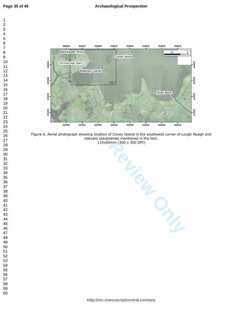
For Peer Review O
nly
Figure 6. Aerial photograph showing location of Coney Island in the southwest corner of Lough Neagh and relevant placenames mentioned in the text.
110x60mm (300 x 300 DPI)
Page 35 of 40
http://mc.manuscriptcentral.com/arp
Archaeological Prospection
123456789101112131415161718192021222324252627282930313233343536373839404142434445464748495051525354555657585960

For Peer Review O
nly
Figure 7. Second Edition (1858-60) Ordnance Survey historic map overlain with bathymetric map generated from SBES data for the area between Coney Island and the mainland. Also shown are the locations of SSS anomalies. Profiles A-A’, B-B’ and C-C’ are taken from the interpolated bathymetric data and cross recorded
(A-A’) and alternative (B-B’, C-C’) routes for St. Patrick’s Road. 193x169mm (300 x 300 DPI)
Page 36 of 40
http://mc.manuscriptcentral.com/arp
Archaeological Prospection
123456789101112131415161718192021222324252627282930313233343536373839404142434445464748495051525354555657585960

For Peer Review O
nly
Figure 8. SSS data showing archaeological objects and anomalies in the vicinity of Coney Island A) Sunken canal barge and associated debris c. 250m south of Coney Island in 2.5m water depth. Data acquired at
800kHz and 20m range. B) Two logboats (indicated by arrows) in 1.6m water depth off the southeast shore
of Coney Island. A number of other upstanding anomalies are also visible in the surrounding area which have not been subject to ground truthing. Data acquired at 455kHz and 25m range. C) Two linear anomalies
c. 300m south of Coney Island in 2.4m depth. These have not been ground-truthed. Data acquired at 800kHz and 12m range. D) Sub-parallel scars on the lakebed c. 180m SW of Coney Island in 1-1.3m water depth. These have not been ground-truthed but their general appearance is suggestive of anchor drag
marks or possibly dredging activity. Data acquired at 455kHz and 30m range 140x143mm (300 x 300 DPI)
Page 37 of 40
http://mc.manuscriptcentral.com/arp
Archaeological Prospection
123456789101112131415161718192021222324252627282930313233343536373839404142434445464748495051525354555657585960
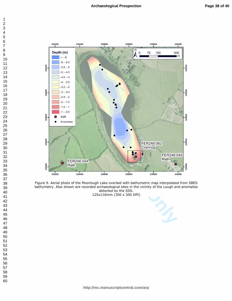
For Peer Review O
nly
Figure 9. Aerial photo of the Moorlough Lake overlaid with bathymetric map interpolated from SBES bathymetry. Also shown are recorded archaeological sites in the vicinity of the Lough and anomalies
detected by the SSS.
125x116mm (300 x 300 DPI)
Page 38 of 40
http://mc.manuscriptcentral.com/arp
Archaeological Prospection
123456789101112131415161718192021222324252627282930313233343536373839404142434445464748495051525354555657585960
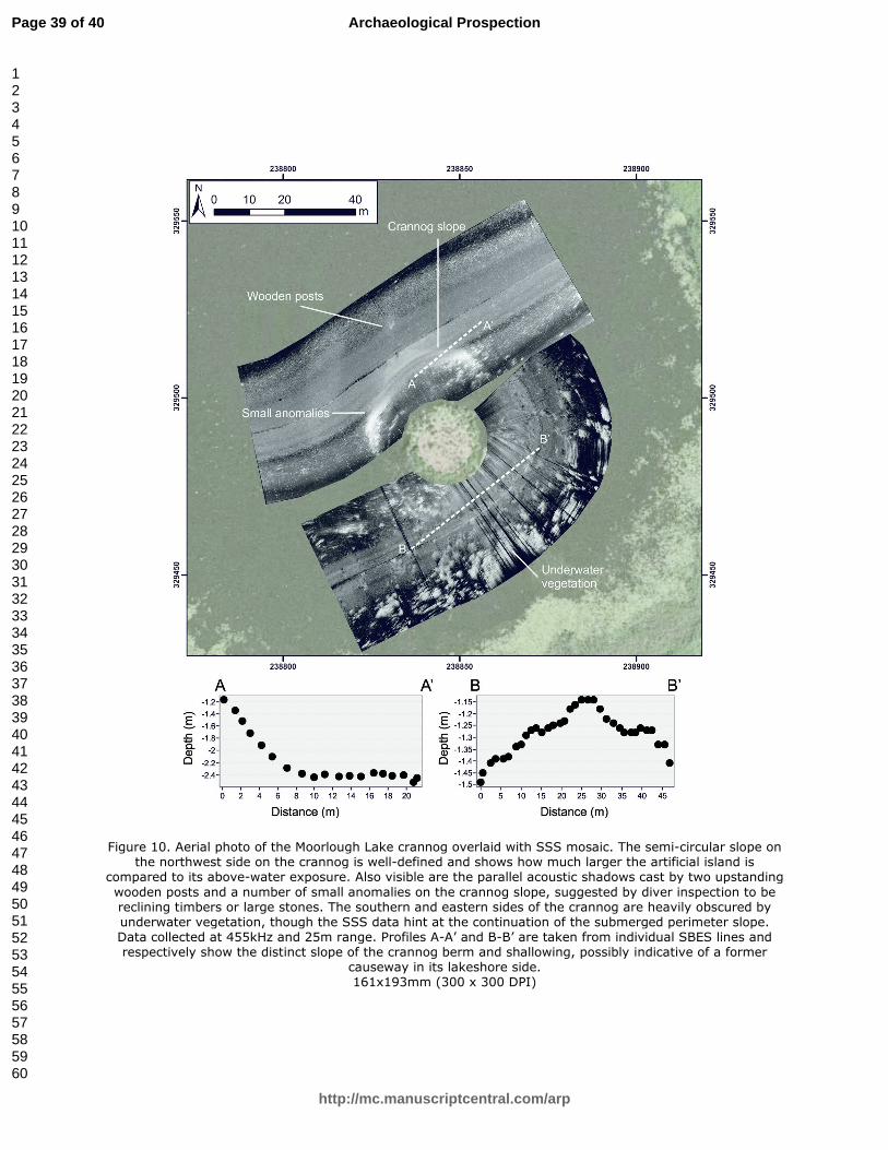
For Peer Review O
nly
Figure 10. Aerial photo of the Moorlough Lake crannog overlaid with SSS mosaic. The semi-circular slope on the northwest side on the crannog is well-defined and shows how much larger the artificial island is
compared to its above-water exposure. Also visible are the parallel acoustic shadows cast by two upstanding
wooden posts and a number of small anomalies on the crannog slope, suggested by diver inspection to be reclining timbers or large stones. The southern and eastern sides of the crannog are heavily obscured by underwater vegetation, though the SSS data hint at the continuation of the submerged perimeter slope. Data collected at 455kHz and 25m range. Profiles A-A’ and B-B’ are taken from individual SBES lines and respectively show the distinct slope of the crannog berm and shallowing, possibly indicative of a former
causeway in its lakeshore side. 161x193mm (300 x 300 DPI)
Page 39 of 40
http://mc.manuscriptcentral.com/arp
Archaeological Prospection
123456789101112131415161718192021222324252627282930313233343536373839404142434445464748495051525354555657585960
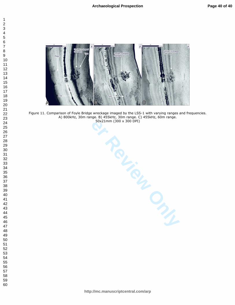
For Peer Review O
nly
Figure 11. Comparison of Foyle Bridge wreckage imaged by the LSS-1 with varying ranges and frequencies. A) 800kHz, 30m range. B) 455kHz, 30m range. C) 455kHz, 60m range.
50x21mm (300 x 300 DPI)
Page 40 of 40
http://mc.manuscriptcentral.com/arp
Archaeological Prospection
123456789101112131415161718192021222324252627282930313233343536373839404142434445464748495051525354555657585960