Embed Size (px)
Citation preview
SUMMARY OF TECHNICAL INFORMATION FOR DESIGNING
ALUMINIUM HEATING BODIES
BIMETALLIC HEATING BODIES
THE CAST-IRON HEATING BODIES
Kalor / Kalor 3 / Termo
Residence
Bohemia / Bohemia RStyl / Hellas
Duostar

Page 3 of 217
CAST-IRON HEATING BODIES
KALOR
Page 4 of 217
KALOR
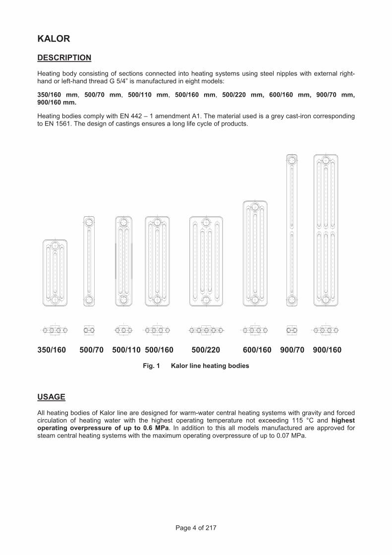
DESCRIPTION Heating body consisting of sections connected into heating systems using steel nipples with external right-hand or left-hand thread G 5/4” is manufactured in eight models:
350/160 mm, 500/70 mm, 500/110 mm, 500/160 mm, 500/220 mm, 600/160 mm, 900/70 mm, 900/160 mm.
Heating bodies comply with EN 442 – 1 amendment A1. The material used is a grey cast-iron corresponding to EN 1561. The design of castings ensures a long life cycle of products.
350/160 500/70 500/110 500/160 500/220 600/160 900/70 900/160
Fig. 1 Kalor line heating bodies
USAGE
All heating bodies of Kalor line are designed for warm-water central heating systems with gravity and forced circulation of heating water with the highest operating temperature not exceeding 115 °C and highest operating overpressure of up to 0.6 MPa. In addition to this all models manufactured are approved for steam central heating systems with the maximum operating overpressure of up to 0.07 MPa.
Page 5 of 217
THERMAL AND TECHNICAL PARAMETERS
Table 1 Significant thermal and technical parameters of Kalor heating sections
Property Symbol Unit 350/160 500/70 500/110 500/160 500/220 600/160 900/70 900/160
Identification number
1 3 5 7 9 11 13 15
Total height H (mm) 430 580 580 580 580 680 980 980
Spacing h (mm) 350 500 500 500 500 600 900 900
Depth B (mm) 160 70 110 160 220 160 70 160
Width L (mm) 60 60 60 60 60 60 60 60
Connection thread
G " 5/4 5/4 5/4 5/4 5/4 5/4 5/4 5/4
Weight M (kg/section) 4,30 3,20 4,00 5,60 6,95 6,60 5,20 10,60
Equivalent heating area
SL (m2/section) 0,185 0,120 0,180 0,255 0,345 0,306 0,205 0,440
Water volume V (dm3/section) 0,8 0,5 0,8 1,1 1,3 1,2 0,8 1,5
Thermal power QTn (W/section) 70 53 73 94 120 110 89 152
Thermal module QM (W/m) 1162 889 1162 1516 1979 1815 1370 2475
Temperature exponent
n (-) 1,250 1,240 1,250 1,250 1,285 1,270 1,280 1,310
All Kalor models are certified by SZÚ Brno. Thermal and technical parameters are verified experimentally in compliance with EN 442_1 amendment A1 Tables 2 through to 33 provide values of thermal power for individual models of cast-iron heating bodies for number of sections ranging from 2 up to 30, variable required air temperature and temperature gradient of the heat-transfer fluid (water) equal to 90/70 °C, 75/65 °C, 55/45 °C and steam.
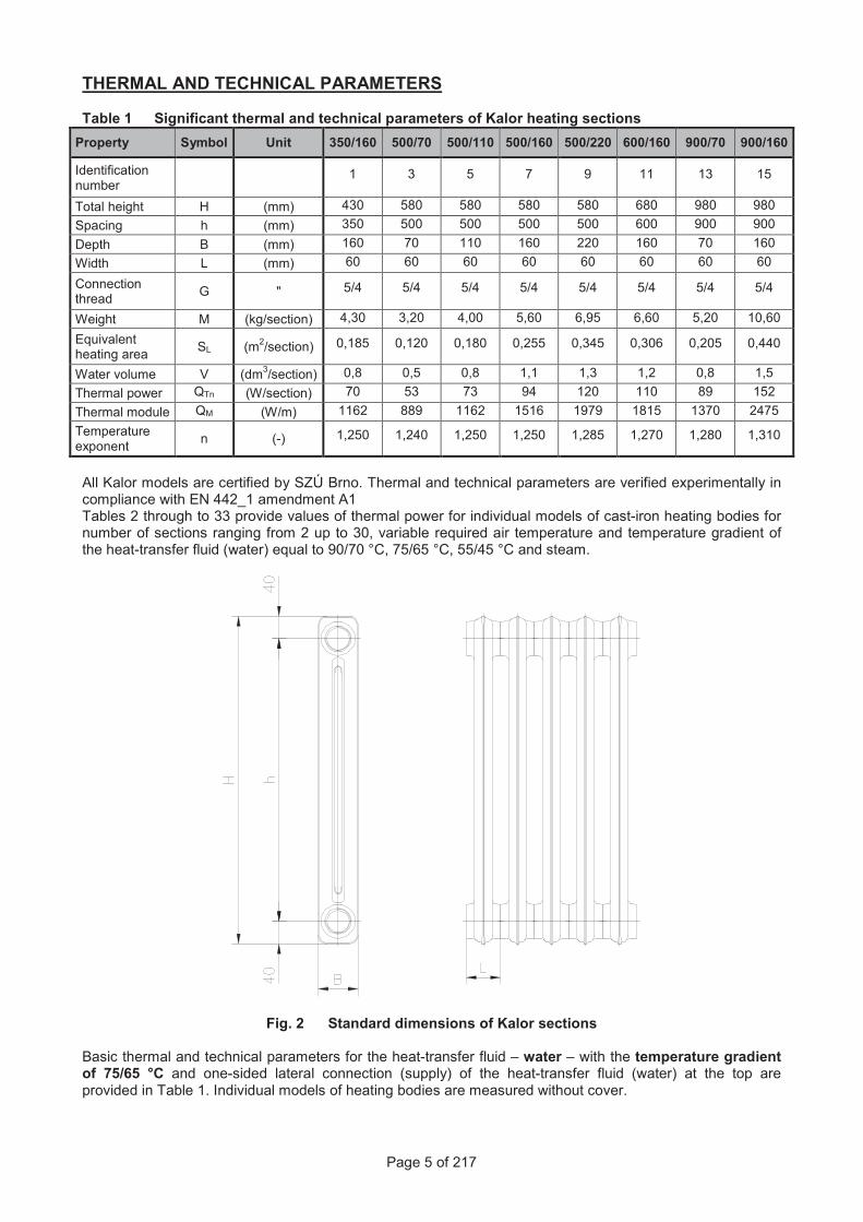
Fig. 2 Standard dimensions of Kalor sections
Basic thermal and technical parameters for the heat-transfer fluid – water – with the temperature gradient of 75/65 °C and one-sided lateral connection (supply) of the heat-transfer fluid (water) at the top are provided in Table 1. Individual models of heating bodies are measured without cover.
Page 6 of 217
TESTING OVERPRESSURE
Units manufactured are subject to the pressure test performed in manufacturer’s facility using overpressure of cold water equal to 1 MPa.
ASSEMBLY
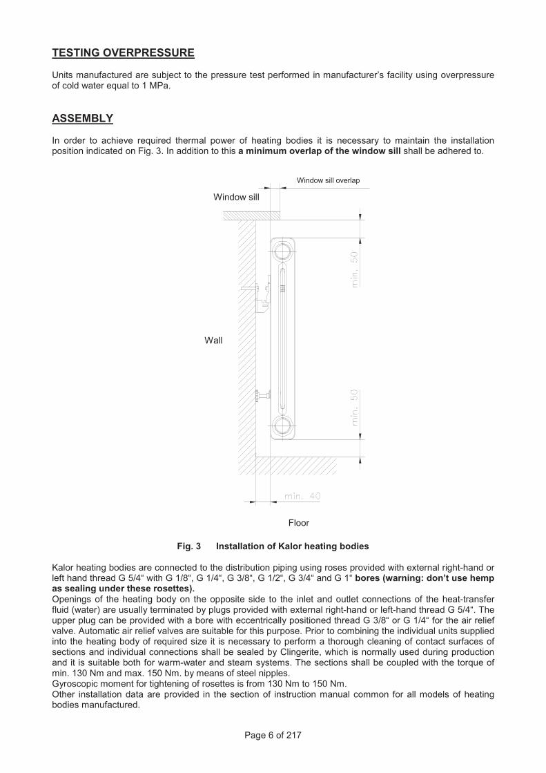
In order to achieve required thermal power of heating bodies it is necessary to maintain the installation position indicated on Fig. 3. In addition to this a minimum overlap of the window sill shall be adhered to.
Fig. 3 Installation of Kalor heating bodies Kalor heating bodies are connected to the distribution piping using roses provided with external right-hand or left hand thread G 5/4“ with G 1/8“, G 1/4“, G 3/8“, G 1/2“, G 3/4“ and G 1“ bores (warning: don’t use hemp as sealing under these rosettes). Openings of the heating body on the opposite side to the inlet and outlet connections of the heat-transfer fluid (water) are usually terminated by plugs provided with external right-hand or left-hand thread G 5/4“. The upper plug can be provided with a bore with eccentrically positioned thread G 3/8“ or G 1/4“ for the air relief valve. Automatic air relief valves are suitable for this purpose. Prior to combining the individual units supplied into the heating body of required size it is necessary to perform a thorough cleaning of contact surfaces of sections and individual connections shall be sealed by Clingerite, which is normally used during production and it is suitable both for warm-water and steam systems. The sections shall be coupled with the torque of min. 130 Nm and max. 150 Nm. by means of steel nipples. Gyroscopic moment for tightening of rosettes is from 130 Nm to 150 Nm. Other installation data are provided in the section of instruction manual common for all models of heating bodies manufactured.
Window sill overlap
Window sill
Wall
Floor

Page 176 of 217
7. Support under KALOR and KALOR 3 heating body
This fixation method is used for KALOR and KALOR 3 heating bodies in combination with holders.
Fig. 11 Support under heating bodies KALOR and KALOR 3
Table 9 Number of supports depending on dimensions of sections KALOR
Dimensions of sections
(mm)
Number of sections
3 4 6 8 10 12 14 16 18 20 22 24 26 28 30
Kalor 350/160 2 3 4 4 4 5 5 Kalor 500/70 2 3 4 4 4 5 5 Kalor 500/110 2 3 4 4 4 5 5 Kalor 500/160 2 3 4 4 4 5 5 Kalor 500/220 2 3 4 4 4 5 5 Kalor 900/70 2 3 4 4 4 5 5 Kalor 900/160 2 3 4 4 4 5 5
Table 10 Number of supports depending on dimensions of sections KALOR 3
Dimensions of sections
(mm)
Number of sections
3 4 6 8 10 12 14 16 18 20 22 24 26 28 30
Kalor 3 350/160 2 3 4 4 4 5 5 Kalor 3 500/70 2 3 4 4 4 5 5 Kalor 3 500/110 2 3 4 4 4 5 5 Kalor 3 500/160 2 3 4 4 4 5 5 Kalor 3 900/70 2 3 4 4 4 5 5
supply number 9213
Dimensions of support:Height 123 mm Width 60 mm Depth 100 mm