Embed Size (px)
Citation preview
8/18/2019 Footing design and analysis
http://slidepdf.com/reader/full/footing-design-and-analysis 1/53
1
Footings
Footings
Definition
Footings are structural members used to support
columns and walls and to transmit and distribute
their loads to the soil in such a way that the load
bearing capacity of the soil is not exceeded,
excessive settlement, differential settlement,or
rotation are prevented and adequate safety
against overturning or sliding is maintained.
8/18/2019 Footing design and analysis
http://slidepdf.com/reader/full/footing-design-and-analysis 2/53
2
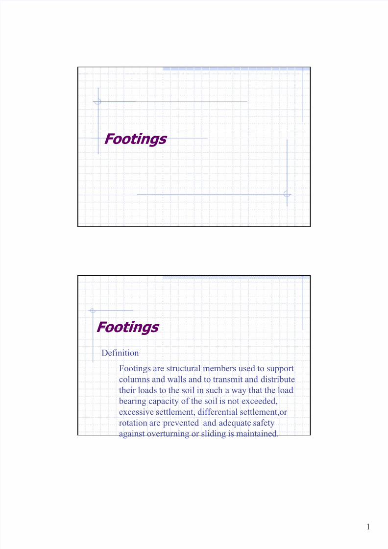
Types of Footings
Wall footings are used to
support structural walls that
carry loads for other floors
or to support nonstructural
walls.
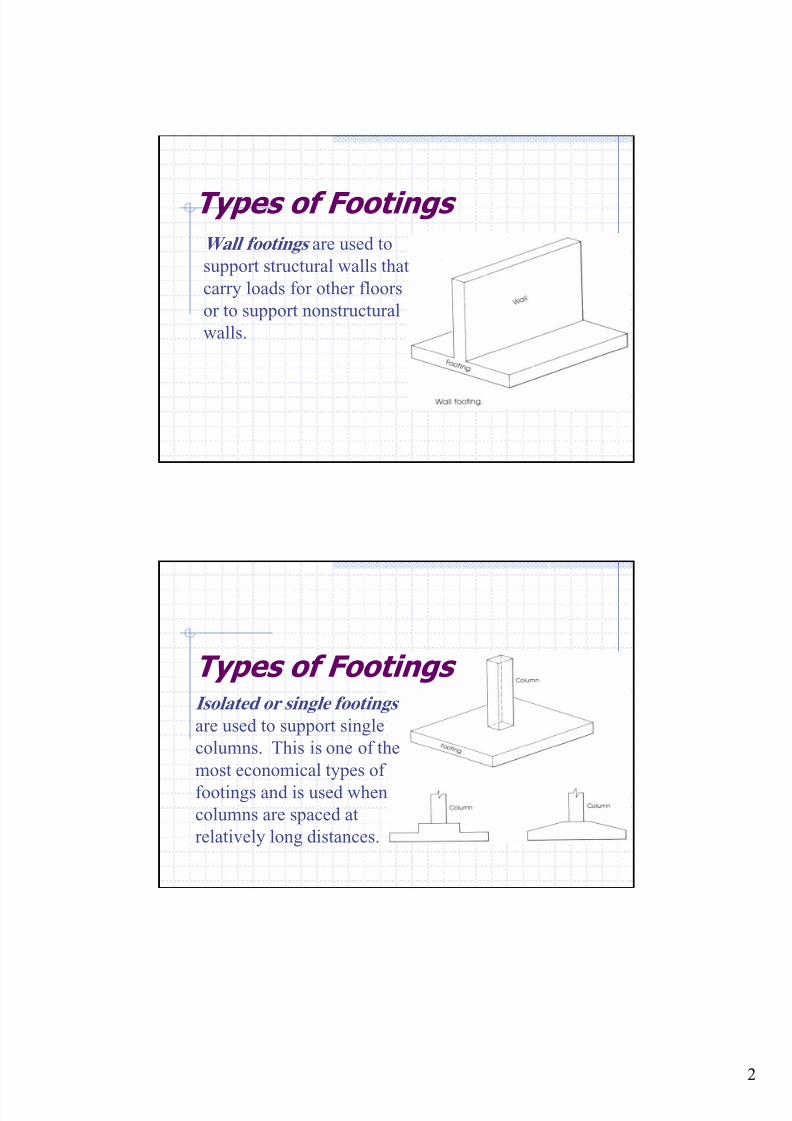
Types of Footings Isolated or single footings
are used to support single
columns. This is one of the
most economical types of
footings and is used when
columns are spaced at
relatively long distances.
8/18/2019 Footing design and analysis
http://slidepdf.com/reader/full/footing-design-and-analysis 3/53
8/18/2019 Footing design and analysis
http://slidepdf.com/reader/full/footing-design-and-analysis 4/53
4
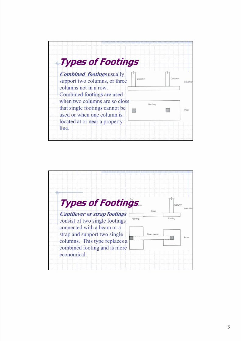
Types of Footings
Continuous footings
support a row of three or
more columns. They have
limited width and continue
under all columns.
Types of Footings Rafted or mat foundation
consists of one footing usually
placed under the entire building
area. They are used, when soil
bearing capacity is low, column
loads are heavy single footings
cannot be used, piles are not used
and differential settlement must
be reduced.
8/18/2019 Footing design and analysis
http://slidepdf.com/reader/full/footing-design-and-analysis 5/53
5
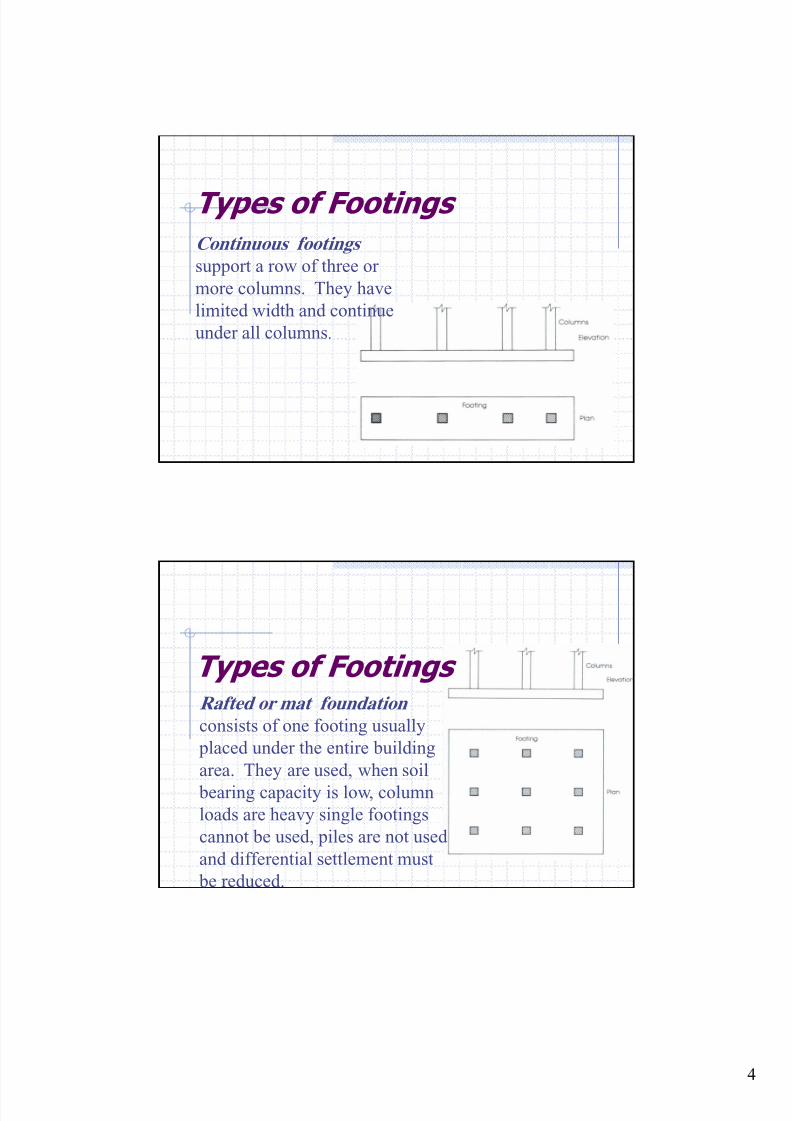
Types of Footings
Pile caps are thick slabs
used to tie a group of piles
together to support and
transmit column loads to the
piles.
Distribution of Soil Pressure
When the column load P is
applied on the centroid of the
footing, a uniform pressure is
assumed to develop on the soilsurface below the footing area.
However the actual distribution of the soil is not uniform,
but depends on may factors especially the composition of
the soil and degree of flexibility of the footing.
8/18/2019 Footing design and analysis
http://slidepdf.com/reader/full/footing-design-and-analysis 6/53
6
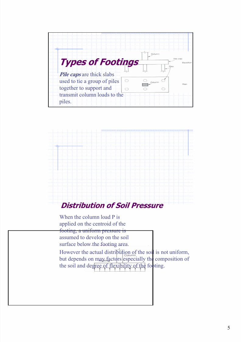
Distribution of Soil Pressure
Soil pressure distribution in
cohesionless soil.
Soil pressure distribution incohesive soil.
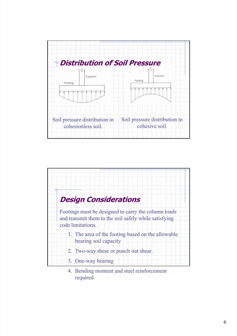
Design Considerations
Footings must be designed to carry the column loads
and transmit them to the soil safely while satisfying
code limitations.
The area of the footing based on the allowable bearing soil capacity
Two-way shear or punch out shear.
One-way bearing
Bending moment and steel reinforcement
required
1.
2.
3.
4.
8/18/2019 Footing design and analysis
http://slidepdf.com/reader/full/footing-design-and-analysis 7/53
7
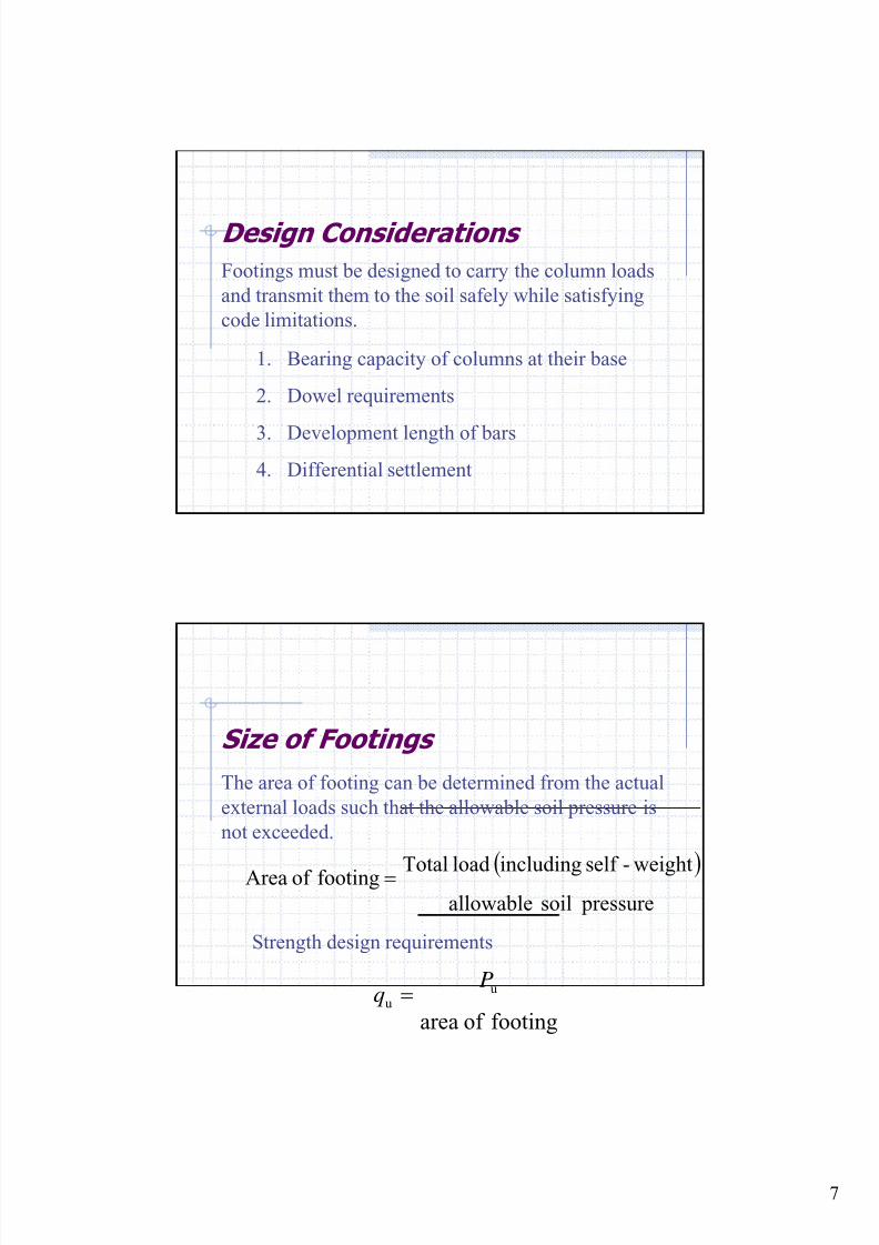
Design Considerations
Footings must be designed to carry the column loads
and transmit them to the soil safely while satisfying
code limitations.
Bearing capacity of columns at their base
Dowel requirements
Development length of bars
Differential settlement
1.
2.
3.
4.
Size of Footings
The area of footing can be determined from the actual
external loads such that the allowable soil pressure is
not exceeded.
( ) pressure soil allowable
weight-self includingload Total footingof Area =
footingof area
uu
Pq =
Strength design requirements
8/18/2019 Footing design and analysis
http://slidepdf.com/reader/full/footing-design-and-analysis 8/53
8
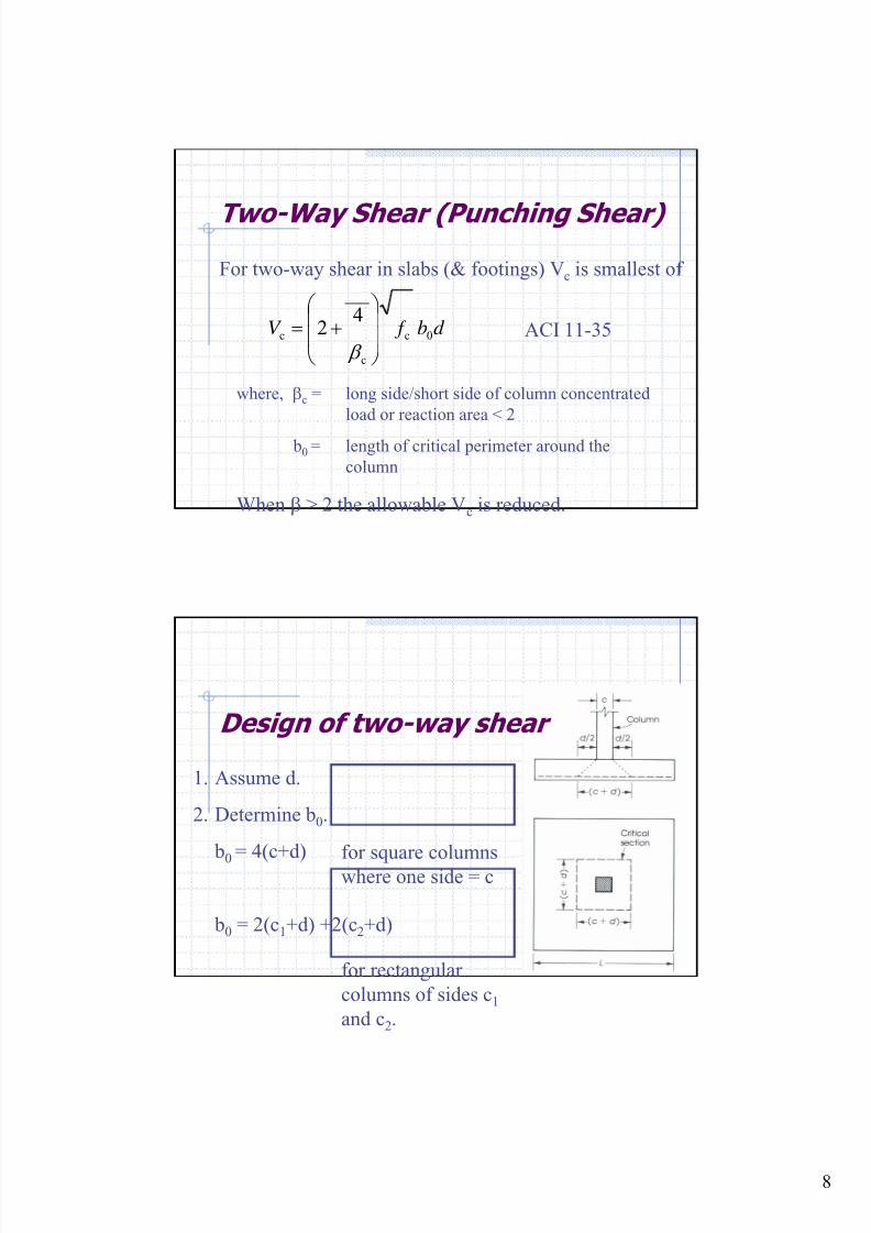
Two-Way Shear (Punching Shear)
For two-way shear in slabs (& footings) Vc is smallest of
long side/short side of column concentrated
load or reaction area < 2
length of critical perimeter around the
column
where, βc =
b0 =
ACI 11-35d b f V 0c
c
c 4
2 ⎟⎟
⎠
⎞
⎜⎜
⎝
⎛ += β
When β > 2 the allowable Vc is reduced.
Design of two-way shear
Assume d.
Determine b0.
b0
= 4(c+d)
b0 = 2(c1+d) +2(c2+d)
1.
2.
for square columns
where one side = c
for rectangular
columns of sides c1
and c2.
8/18/2019 Footing design and analysis
http://slidepdf.com/reader/full/footing-design-and-analysis 9/53
9
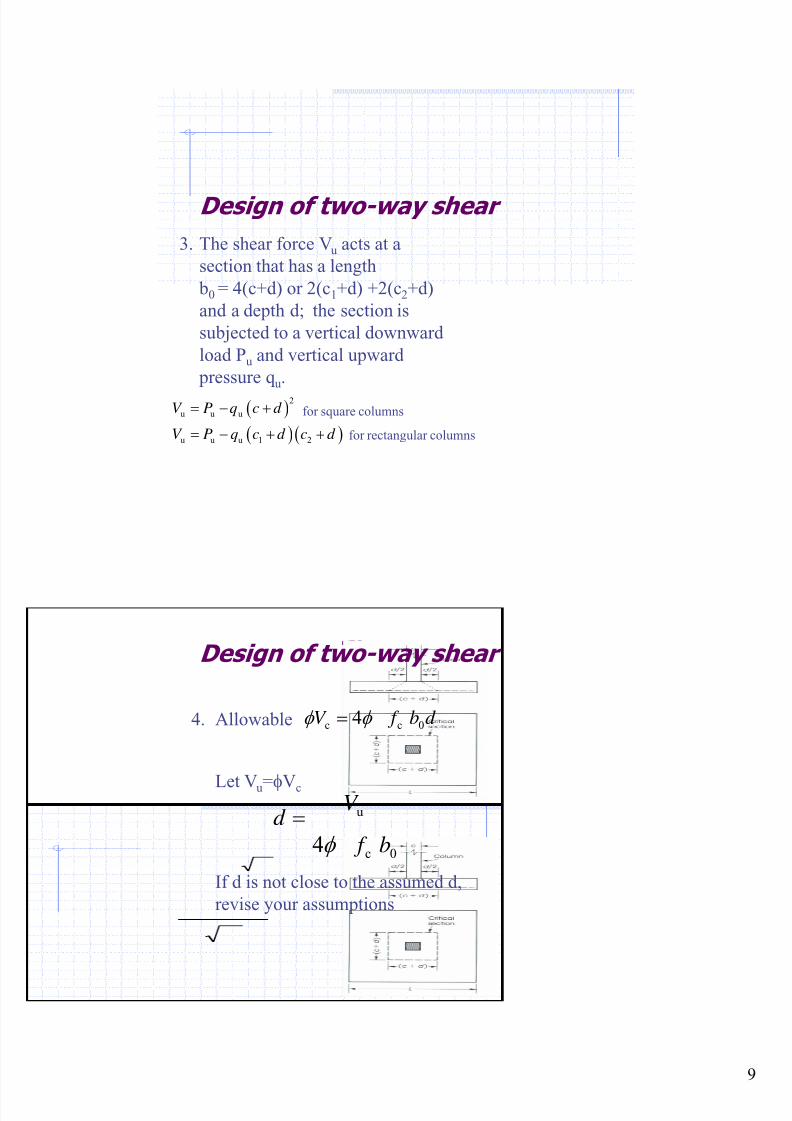
Design of two-way shear
The shear force Vu acts at a
section that has a length
b0 = 4(c+d) or 2(c1+d) +2(c2+d)
and a depth d; the section is
subjected to a vertical downward
load Pu and vertical upward
pressure q u.
3.
( )
( ) ( )
2
u u u
u u u 1 2
V P q c d
V P q c d c d
= − +
= − + +
for square columns
for rectangular columns
Design of two-way shear
Allowable
Let Vu=φVc
4. d b f V 0cc 4φ φ =
0c
u
4 b f
V d
φ
=
If d is not close to the assumed d,
revise your assumptions
8/18/2019 Footing design and analysis
http://slidepdf.com/reader/full/footing-design-and-analysis 10/53
10
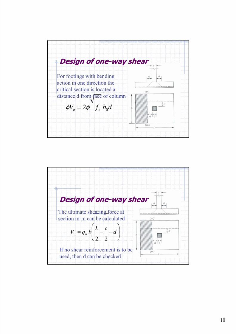
Design of one-way shear
For footings with bending
action in one direction the
critical section is located a
distance d from face of column
d b f V 0cc 2φ φ =
Design of one-way shear
The ultimate shearing force at
section m-m can be calculated
⎟⎟ ⎠
⎞
⎜⎜⎝
⎛
−−= d
c L
bqV 22 uu
If no shear reinforcement is to be
used, then d can be checked
8/18/2019 Footing design and analysis
http://slidepdf.com/reader/full/footing-design-and-analysis 11/53
11
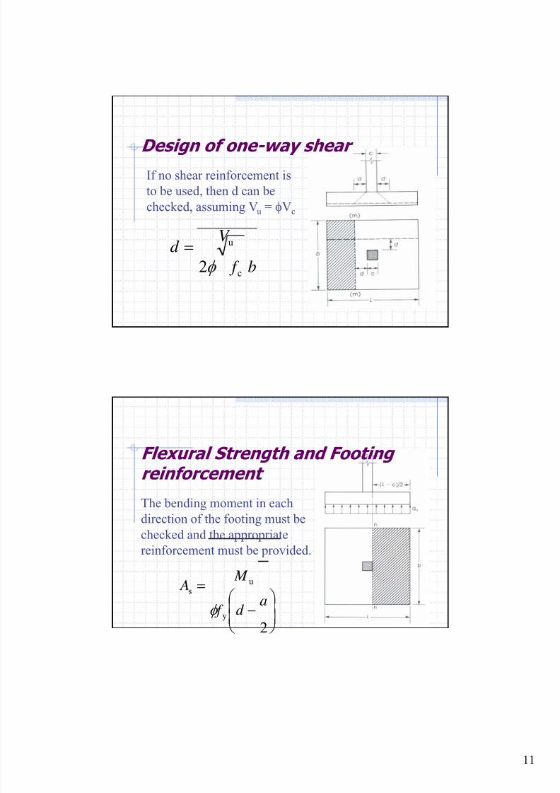
Design of one-way shear
b f
V d
2c
u
φ
=
If no shear reinforcement is
to be used, then d can be
checked, assuming Vu = φVc
Flexural Strength and Footingreinforcement
2y
us
⎟⎟
⎠
⎞⎜⎜⎝
⎛ −
=a
d f
M A
φ
The bending moment in each
direction of the footing must be
checked and the appropriate
reinforcement must be provided.
8/18/2019 Footing design and analysis
http://slidepdf.com/reader/full/footing-design-and-analysis 12/53
12
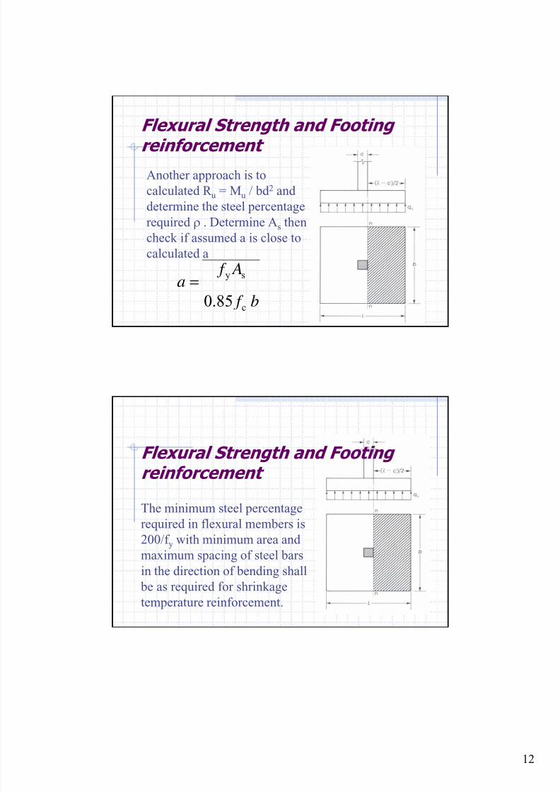
Flexural Strength and Footingreinforcement
b f A f a
85.0 c
sy=
Another approach is to
calculated R u = Mu / bd 2 and
determine the steel percentage
required ρ . Determine As then
check if assumed a is close to
calculated a
Flexural Strength and Footingreinforcement
The minimum steel percentage
required in flexural members is
200/f y with minimum area and
maximum spacing of steel barsin the direction of bending shall
be as required for shrinkage
temperature reinforcement.
8/18/2019 Footing design and analysis
http://slidepdf.com/reader/full/footing-design-and-analysis 13/53
13
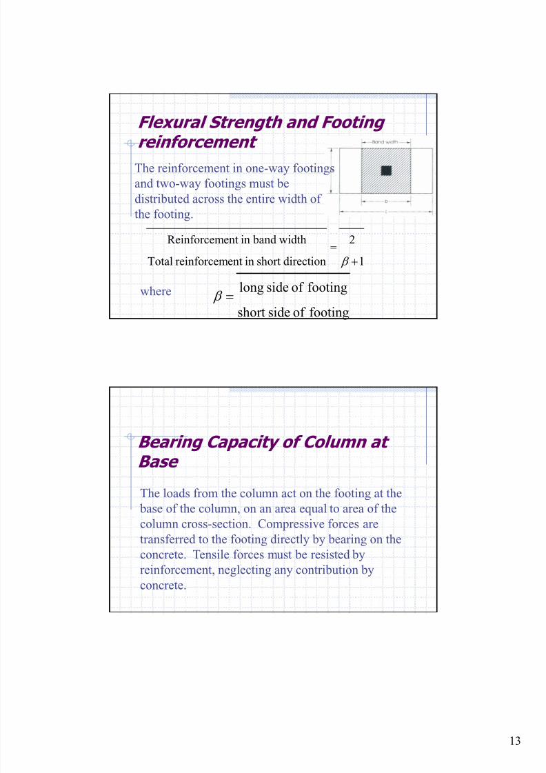
Flexural Strength and Footingreinforcement
The reinforcement in one-way footings
and two-way footings must be
distributed across the entire width of
the footing.
1
2
directionshortinentreinforcemTotal
width band inentReinforcem
+= β
footingof sideshort
footingof sidelong= β where
Bearing Capacity of Column atBase
The loads from the column act on the footing at the
base of the column, on an area equal to area of the
column cross-section. Compressive forces are
transferred to the footing directly by bearing on theconcrete. Tensile forces must be resisted by
reinforcement, neglecting any contribution by
concrete.
8/18/2019 Footing design and analysis
http://slidepdf.com/reader/full/footing-design-and-analysis 14/53
14
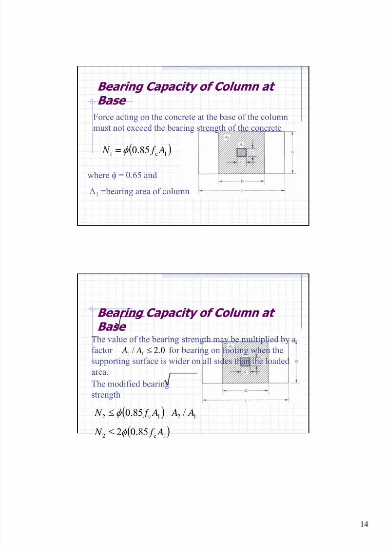
Bearing Capacity of Column atBase
Force acting on the concrete at the base of the column
must not exceed the bearing strength of the concrete
( )1c1 85.0 A f N φ =
where φ = 0.65 and
A1 =bearing area of column
Bearing Capacity of Column atBase
The value of the bearing strength may be multiplied by a
factor for bearing on footing when the
supporting surface is wider on all sides than the loaded
area.
0.2/ 12 ≤ A A
The modified bearingstrength
( )
( )1c2
121c2
85.02
/85.0
A f N
A A A f N
φ
φ
≤
≤

8/18/2019 Footing design and analysis
http://slidepdf.com/reader/full/footing-design-and-analysis 15/53
15
Dowels in Footings
A minimum steel ratio ρ = 0.005 of the column section
as compared to ρ = 0.01 as minimum reinforcement for
the column itself. The number of dowel bars needed is
four these may be placed at the four corners of the
column. The dowel bars are usually extended into the
footing, bent at the ends, and tied to the main footing
reinforcement. The dowel diameter shall not exceed
the diameter of the longitudinal bars in the column by
more than 0.15 in.
Development length of theReinforcing Bars
The development length for compression bars was given
but not less than
Dowel bars must be checked for proper development
length.
c byd /02.0 f d f l =
in.8003.0 by ≥d f
8/18/2019 Footing design and analysis
http://slidepdf.com/reader/full/footing-design-and-analysis 16/53
16
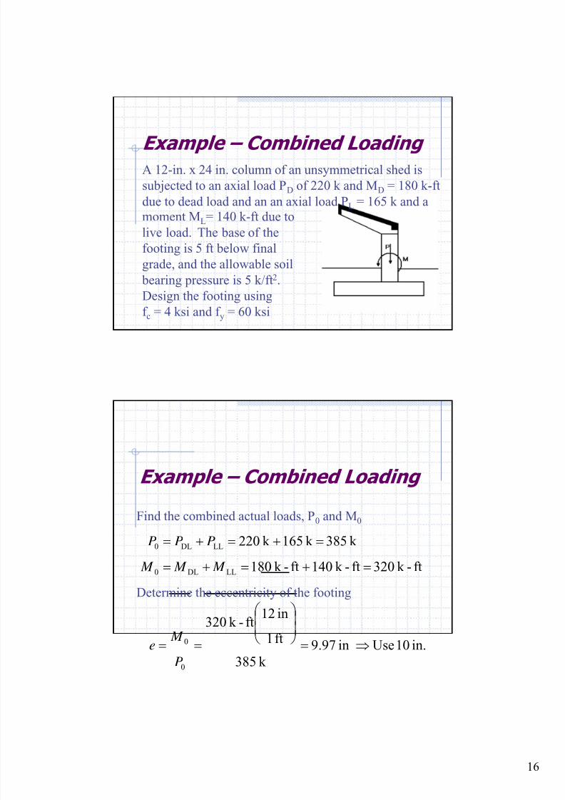
Example – Combined Loading
A 12-in. x 24 in. column of an unsymmetrical shed is
subjected to an axial load PD of 220 k and MD = 180 k-ft
due to dead load and an an axial load PL = 165 k and a
moment ML= 140 k-ft due to
live load. The base of the
footing is 5 ft below final
grade, and the allowable soil
bearing pressure is 5 k/ft2.Design the footing using
f c = 4 ksi and f y = 60 ksi
Example – Combined Loading
Find the combined actual loads, P0 and M0
ft-k 320ft-k 140ft-k 180
k 385k165k220
LLDL0
LLDL0
=+=+=
=+=+=
M M M
PPP
Determine the eccentricity of the footing
in.10Usein97.9
k 385
ft1
in12ft-k 320
0
0 ⇒=⎟⎟ ⎠
⎞⎜⎜⎝
⎛
==P
M e
8/18/2019 Footing design and analysis
http://slidepdf.com/reader/full/footing-design-and-analysis 17/53
17
Example – Combined Loading
Assume a depth of footing, 24 in. The weight of
concrete and the soil are:
23
c lb/ft300
in.12
ft.1*in.24*lb/ft150 === d W γ
23
sss lb/ft300
in.12
ft.1*in.24ft5*lb/ft100 =⎟
⎟ ⎠
⎞⎜⎜⎝
⎛ −== d W γ
Example – Combined Loading
The effective soil pressure is given as:
22
222
scseff
k/ft4.4lb/ft4400
lb/ft300lb/ft300lb/ft5000
⇒=
−−=
−−= W W qq
8/18/2019 Footing design and analysis
http://slidepdf.com/reader/full/footing-design-and-analysis 18/53
8/18/2019 Footing design and analysis
http://slidepdf.com/reader/full/footing-design-and-analysis 19/53
19
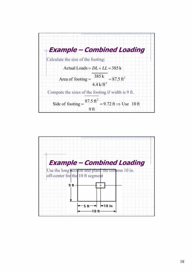
Example – Combined Loading
Calculate net upward pressure:
( ) ( )
( )( )2
n
ftk /5.87
ft01ft9
k528.0
pressureupward Net
k 528.0
k 1651.6k 2022.1
6.12.1LoadsActual
=
=
=
+=
+=
q
LL DL
Example – Combined Loading
Calculate the depth of the reinforcement use # 8 bars
with a crisscrossing layering.
( )
in.5.19
in0.15.1in3in.24
5.1cover b
=
−−=
−−=
d
d hd
8/18/2019 Footing design and analysis
http://slidepdf.com/reader/full/footing-design-and-analysis 20/53
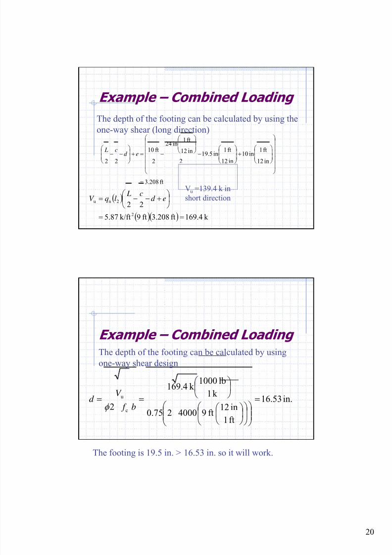
20
Example – Combined Loading
( )
( )( ) k 4.169ft208.3ft9k/ft87.5
22
2
2nu
==
⎟ ⎠ ⎞⎜
⎝ ⎛ +−−= ed c LlqV
ft208.3
in12
ft1in10
in12
ft1in5.19
2
in12
ft1in42
2
ft10
22
=
⎟⎟⎟⎟⎟
⎠
⎞
⎜⎜⎜⎜⎜
⎝
⎛
⎟⎟ ⎠
⎞⎜⎜⎝
⎛ +⎟
⎟ ⎠
⎞⎜⎜⎝
⎛ −
⎟⎟ ⎠
⎞⎜⎜⎝
⎛
−=+⎟⎟ ⎠
⎞⎜⎜⎝
⎛ −− ed
c L
Vu =139.4 k in
short direction
The depth of the footing can be calculated by using the
one-way shear (long direction)
Example – Combined LoadingThe depth of the footing can be calculated by using
one-way shear design
in.53.16
ft1
in12ft9400020.75
k 1
lb1000
k 4.169
2 c
u =
⎟⎟ ⎠
⎞⎜⎜⎝
⎛ ⎟
⎠
⎞⎜⎝
⎛ ⎟
⎠
⎞⎜⎝
⎛ ⎟ ⎠
⎞⎜⎝ ⎛
==b f
V d
φ
The footing is 19.5 in. > 16.53 in. so it will work.
8/18/2019 Footing design and analysis
http://slidepdf.com/reader/full/footing-design-and-analysis 21/53
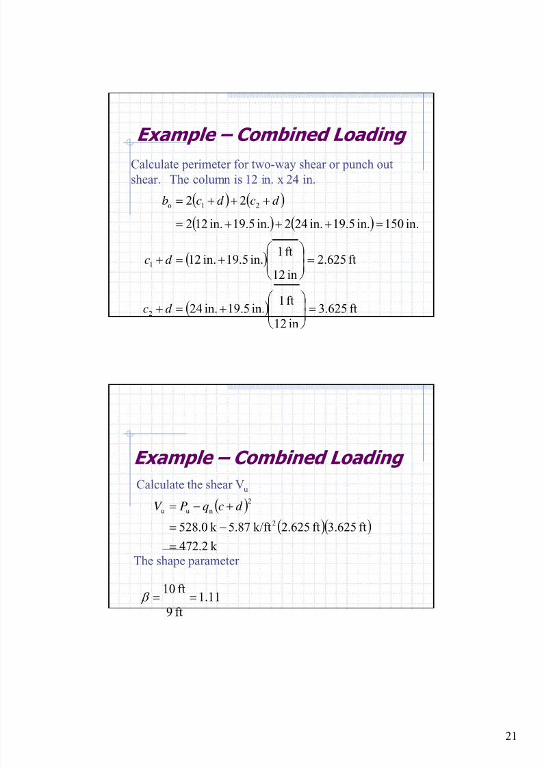
21
Example – Combined LoadingCalculate perimeter for two-way shear or punch out
shear. The column is 12 in. x 24 in.
( ) ( )
( ) ( )
( )
( ) ft625.3
in12
ft1in.5.19in.24
ft625.2
in12
ft1in.5.19in.12
in.150in.5.19in.242in.5.19in.122
22
2
1
21o
=⎟⎟
⎠
⎞⎜⎜⎝
⎛ +=+
=⎟
⎟
⎠
⎞
⎜
⎜
⎝
⎛ +=+
=+++=
+++=
d c
d c
d cd cb
Example – Combined Loading
Calculate the shear Vu
( )
( )( )k 2.472
ft625.3ft625.2k/ft5.87k0.5282
2
nuu
=
−=
+−= d cqPV
11.1
ft9
ft10== β
The shape parameter
8/18/2019 Footing design and analysis
http://slidepdf.com/reader/full/footing-design-and-analysis 22/53
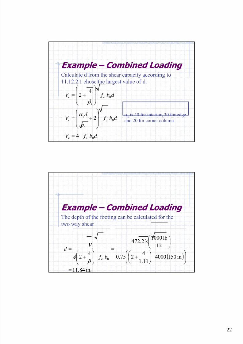
22
Example – Combined LoadingCalculate d from the shear capacity according to
11.12.2.1 chose the largest value of d.
d b f V 0c
c
c 4
2 ⎟⎟
⎠
⎞
⎜⎜
⎝
⎛ += β
d b f V 0cc 4=
d b f b
d
V 0c
o
s
c 2⎟
⎟
⎠
⎞
⎜
⎜
⎝
⎛
+=
α αs is 40 for interior, 30 for edge
and 20 for corner column
Example – Combined LoadingThe depth of the footing can be calculated for the
two way shear
( )
in.84.11
in150400011.1
420.75
k 1
lb1000k 2.472
4
2 0c
u
=
⎟ ⎠
⎞⎜⎝
⎛ ⎟ ⎠
⎞⎜⎝
⎛ +
⎟ ⎠ ⎞⎜⎝ ⎛ =
⎟⎟ ⎠
⎞⎜⎜⎝
⎛ +
=
b f
V d
β φ
8/18/2019 Footing design and analysis
http://slidepdf.com/reader/full/footing-design-and-analysis 23/53
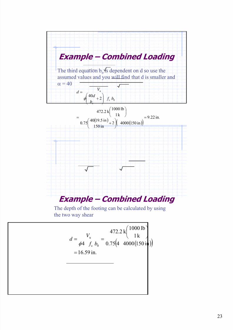
23
Example – Combined LoadingThe third equation bo is dependent on d so use the
assumed values and you will find that d is smaller and
α = 40
( )( )( )
in.22.9
in15040002in150
in9.51400.75
k 1
lb1000k 2.472
240
0c
o
u
=⎟
⎠ ⎞
⎜⎝ ⎛ +
⎟
⎠
⎞⎜
⎝
⎛
=
⎟⎟ ⎠
⎞⎜⎜⎝
⎛ +
=
b f b
d
V d
φ
Example – Combined LoadingThe depth of the footing can be calculated by using
the two way shear
( )( )in.59.16
in150400040.75
k 1
lb1000k 72.24
4 0c
u
=
⎟ ⎠ ⎞⎜⎝ ⎛ ==
b f
V d
φ
8/18/2019 Footing design and analysis
http://slidepdf.com/reader/full/footing-design-and-analysis 24/53
24
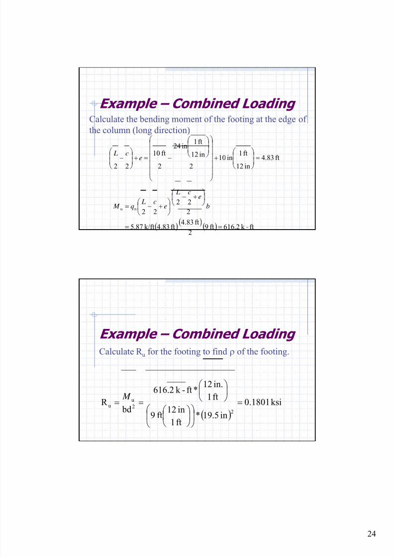
Example – Combined LoadingCalculate the bending moment of the footing at the edge of
the column (long direction)
ft83.4
in12
ft1in10
2
in12
ft1in24
2
ft10
22
=⎟⎟
⎠
⎞⎜⎜⎝
⎛ +
⎟⎟⎟⎟⎟
⎠
⎞
⎜⎜⎜⎜⎜
⎝
⎛
⎟⎟
⎠
⎞⎜⎜⎝
⎛
−=+⎟⎟
⎠
⎞⎜⎜⎝
⎛ − e
c L
( )( )
( ) ft-k 2.616ft92
ft83.4ft83.4k/ft87.5
2
22
22nu
==
⎟ ⎠ ⎞⎜⎝ ⎛ +−⎟
⎠
⎞⎜⎝
⎛ +−= b
ec L
ec L
q M
Example – Combined LoadingCalculate R u for the footing to find ρ of the footing.
( )ksi1801.0
in5.19*ft1
in12ft9
ft1
in.12*ft-k 2.616
bd R
22
uu =
⎟ ⎠
⎞⎜⎝
⎛ ⎟
⎠ ⎞
⎜⎝ ⎛
⎟ ⎠ ⎞
⎜⎝ ⎛
== M
8/18/2019 Footing design and analysis
http://slidepdf.com/reader/full/footing-design-and-analysis 25/53
25
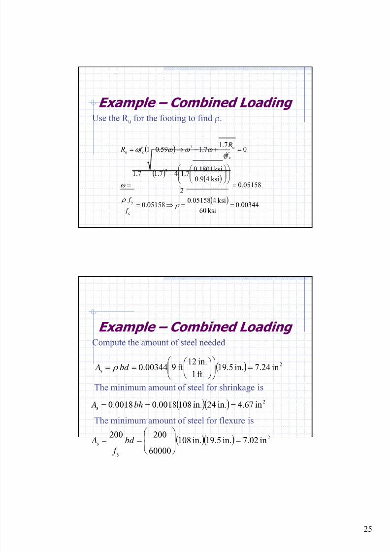
Example – Combined LoadingUse the R u for the footing to find ρ.
( )
( )( )
( )00344.0
ksi60
ksi405158.005158.0
05158.0
2
ksi49.0
ksi1801.07.147.17.1
07.1
7.159.01
c
y
2
c
u2
cu
==⇒=
=⎟⎟
⎠
⎞⎜⎜⎝
⎛ ⎟⎟
⎠
⎞⎜⎜⎝
⎛ −−
=
=+−⇒−=
ρ ρ
ω
φ ω ω ω ω
f
f
f
R f R
Example – Combined LoadingCompute the amount of steel needed
( ) 2
s in24.7in.5.19ft1
in.12ft900344.0 =⎟⎟
⎠
⎞⎜⎜⎝
⎛ ⎟ ⎠
⎞⎜⎝
⎛ == bd A ρ
The minimum amount of steel for shrinkage is
( )( ) 2
s in67.4in.24in.1080018.00018.0 === bh A
The minimum amount of steel for flexure is
( )( ) 2
y
s in02.7in.9.51in.108
60000
200
200=⎟
⎟ ⎠
⎞⎜⎜⎝
⎛ == bd
f
A

8/18/2019 Footing design and analysis
http://slidepdf.com/reader/full/footing-design-and-analysis 26/53
26
Example – Combined LoadingUse As =8.36 in2 with #8 bars (0.79 in2). Compute
the number of bars need
bars11Use25.10
in79.0
in1.8
2
2
b
s ⇒=== A
An
Determine the spacing between bars
( )( ) in2.10
10
in32-in108
1
cover *2 ==−
−=n
Ls
Example – Combined Loading
Calculate the bending moment of the footing at the
edge of the column for short length
ft42
in12
ft1in12
2
ft9
22 =⎟⎟⎟
⎟⎟
⎠
⎞
⎜⎜⎜
⎜⎜
⎝
⎛
⎟⎟
⎠
⎞⎜⎜⎝
⎛
−=⎟⎟ ⎠
⎞
⎜⎜⎝
⎛
−
c L
( )( )
( )
ft-k 6.469
ft102
ft4ft4k/ft87.5
2
22
22nu
=
=⎟ ⎠ ⎞
⎜⎝ ⎛ −
⎟ ⎠
⎞⎜⎝
⎛ −= b
c L
c Lq M
8/18/2019 Footing design and analysis
http://slidepdf.com/reader/full/footing-design-and-analysis 27/53
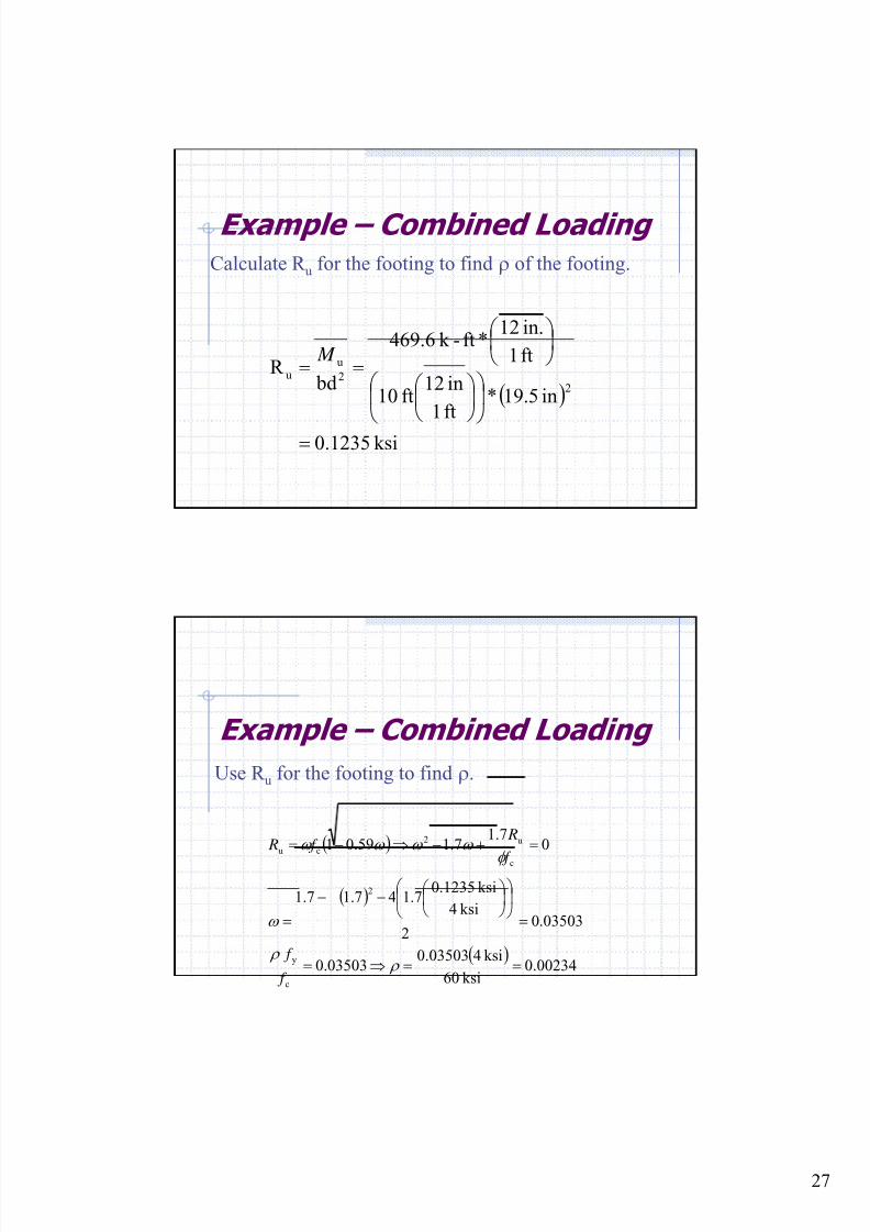
27
Example – Combined LoadingCalculate R u for the footing to find ρ of the footing.
( )
ksi1235.0
in5.19*ft1
in12ft10
ft1
in.12*ft-k 69.64
bd R
22
uu
=
⎟ ⎠
⎞⎜⎝
⎛ ⎟
⎠ ⎞
⎜⎝ ⎛
⎟ ⎠ ⎞
⎜⎝ ⎛
== M
Example – Combined Loading
Use R u for the footing to find ρ.
( )
( )
( )00234.0
ksi60
ksi403503.003503.0
03503.02
ksi4
ksi1235.07.147.17.1
07.1
7.159.01
c
y
2
c
u2
cu
==⇒=
=
⎟ ⎠
⎞⎜⎝
⎛ ⎟
⎠
⎞⎜⎝
⎛ −−
=
=+−⇒−=
ρ ρ
ω
φ
ω ω ω ω
f
f
f
R f R
8/18/2019 Footing design and analysis
http://slidepdf.com/reader/full/footing-design-and-analysis 28/53
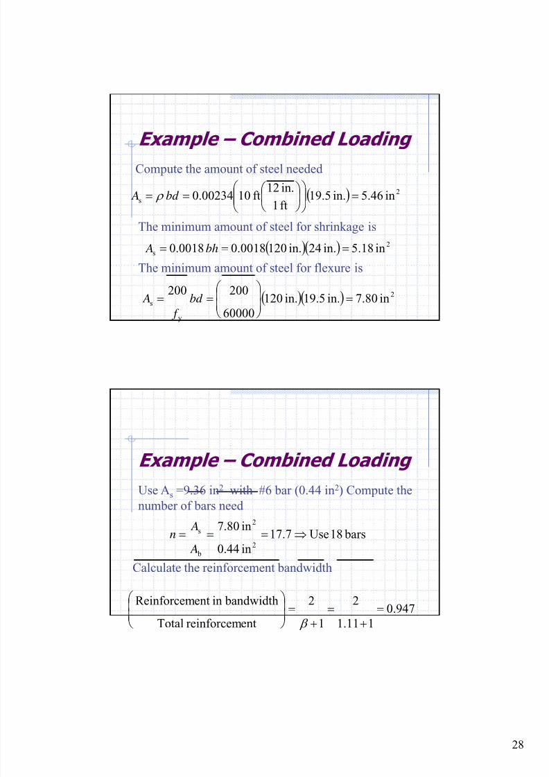
28
Example – Combined Loading
Compute the amount of steel needed
( ) 2
s in46.5in.5.19ft1
in.12ft1000234.0 =⎟⎟
⎠
⎞⎜⎜⎝
⎛ ⎟ ⎠
⎞⎜⎝
⎛ == bd A ρ
The minimum amount of steel for shrinkage is
( )( ) 2
s in18.5in.24in.1200018.00018.0 === bh A
The minimum amount of steel for flexure is
( )( ) 2
y
s in80.7in.9.51in.120
60000
200
200=⎟
⎟ ⎠
⎞⎜⎜⎝
⎛ == bd
f
A
Example – Combined Loading
Use As =9.36 in2 with #6 bar (0.44 in2) Compute the
number of bars need
bars18Use7.17
in44.0
in.807
2
2
b
s ⇒=== A
An
Calculate the reinforcement bandwidth
947.0
111.1
2
1
2
entreinforcemTotal
bandwidthinentReinforcem=
+=
+=⎟
⎟ ⎠
⎞⎜⎜⎝
⎛
β
8/18/2019 Footing design and analysis
http://slidepdf.com/reader/full/footing-design-and-analysis 29/53
29
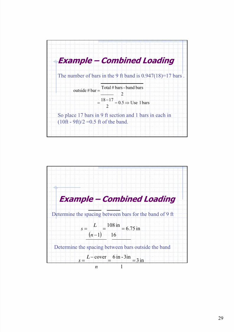
Example – Combined Loading
The number of bars in the 9 ft band is 0.947(18)=17 bars .
So place 17 bars in 9 ft section and 1 bars in each in(10ft - 9ft)/2 =0.5 ft of the band.
bars1 Use5.02
1718
2
bars band - bars#Total bar#outside
⇒=−
=
=
Example – Combined Loading
Determine the spacing between bars for the band of 9 ft
( )in75.6
16
in108
1
==−
=n
Ls
Determine the spacing between bars outside the band
in3
1
3in-in6cover ==
−=
n
Ls
8/18/2019 Footing design and analysis
http://slidepdf.com/reader/full/footing-design-and-analysis 30/53
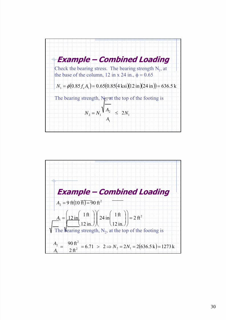
30
Example – Combined LoadingCheck the bearing stress. The bearing strength N1, at
the base of the column, 12 in x 24 in., φ = 0.65
( ) ( )( )( )( ) k 5.636in42in12ksi485.065.085.0 1c1 === A f N φ
The bearing strength, N2, at the top of the footing is
1
1
212 2 N
A A N N ≤=
Example – Combined Loading
The bearing strength, N2, at the top of the footing is
( ) k 1273k 636.5222 6.71ft2
ft90122
2
1
2 ===⇒>== N N A
A
( )
2
1
2
2
ft2
in.12
ft1in42
in.12
ft1in12
ft90ft10ft9
=⎟⎟
⎠
⎞
⎜⎜
⎝
⎛
⎟⎟
⎠
⎞⎜⎜
⎝
⎛
⎟⎟
⎠
⎞
⎜⎜
⎝
⎛
⎟⎟
⎠
⎞⎜⎜
⎝
⎛ =
==
A
A
8/18/2019 Footing design and analysis
http://slidepdf.com/reader/full/footing-design-and-analysis 31/53
31
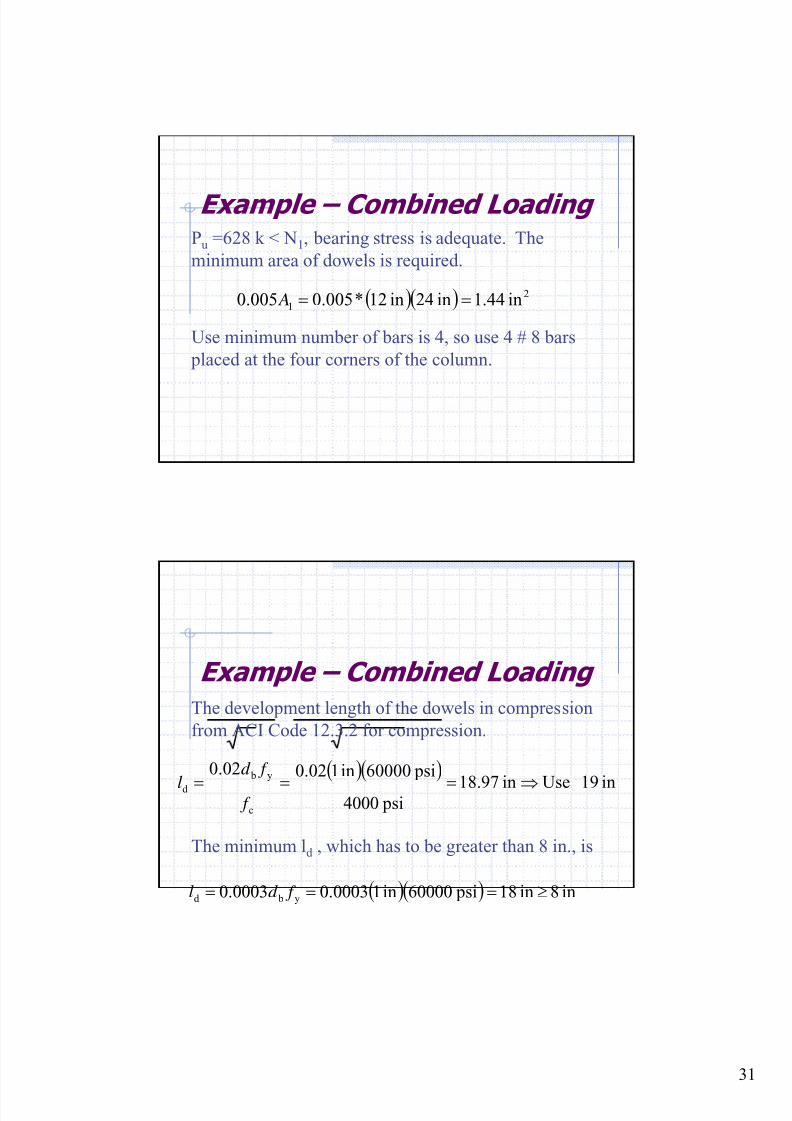
Example – Combined LoadingPu =628 k < N1, bearing stress is adequate. The
minimum area of dowels is required.
( )( ) 2
1 in44.1in42in12*005.0005.0 == A
Use minimum number of bars is 4, so use 4 # 8 bars
placed at the four corners of the column.
Example – Combined Loading
The development length of the dowels in compression
from ACI Code 12.3.2 for compression.
( )( )in19 Usein97.18
psi4000
psi60000in102.002.0
c
y b
d ⇒=== f
f d
l
The minimum ld , which has to be greater than 8 in., is
( )( ) in8in18 psi60000in10003.00003.0 y bd ≥=== f d l
8/18/2019 Footing design and analysis
http://slidepdf.com/reader/full/footing-design-and-analysis 32/53
32
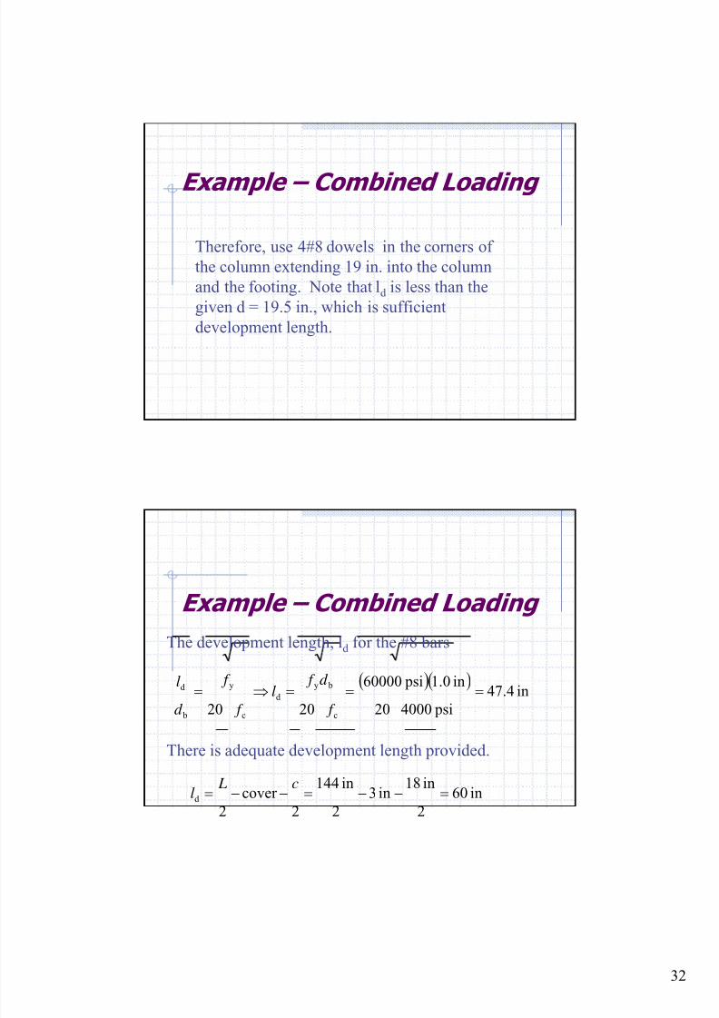
Example – Combined Loading
Therefore, use 4#8 dowels in the corners of
the column extending 19 in. into the column
and the footing. Note that ld is less than the
given d = 19.5 in., which is sufficient
development length.
Example – Combined Loading
The development length, ld for the #8 bars
( )( )in4.47
psi400020
in0.1 psi60000
2020 c
by
d
c
y
b
d ===⇒=
f
d f l
f
f
d
l
There is adequate development length provided.
in60
2
in18in3
2
in144
2
cover
2d =−−=−−=
c Ll
8/18/2019 Footing design and analysis
http://slidepdf.com/reader/full/footing-design-and-analysis 33/53
33
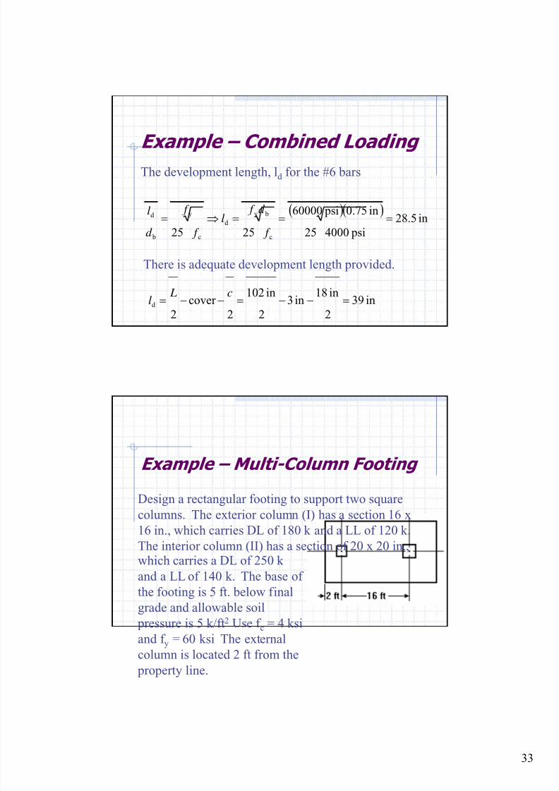
Example – Combined Loading
The development length, ld for the #6 bars
( )( )in5.28
psi400025
in75.0 psi60000
2525 c
by
d
c
y
b
d ===⇒= f
d f l
f
f
d
l
There is adequate development length provided.
in39
2
in18in3
2
in102
2
cover
2d =−−=−−=
c Ll
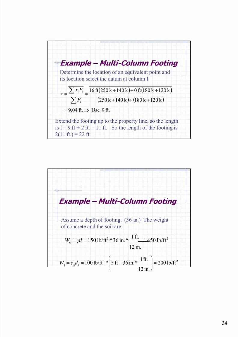
Example – Multi-Column Footing
Design a rectangular footing to support two square
columns. The exterior column (I) has a section 16 x
16 in., which carries DL of 180 k and a LL of 120 k.
The interior column (II) has a section of 20 x 20 in.,which carries a DL of 250 k
and a LL of 140 k. The base of
the footing is 5 ft. below final
grade and allowable soil
pressure is 5 k/ft2 Use f c = 4 ksi
and f y = 60 ksi The external
column is located 2 ft from the
property line.
8/18/2019 Footing design and analysis
http://slidepdf.com/reader/full/footing-design-and-analysis 34/53
34
Example – Multi-Column FootingDetermine the location of an equivalent point and
its location select the datum at column I
( ) ( )
( ) ( )
ft.9 Useft.04.9
k 120k 180k 140k 250
k 120k 180ft0k 140k 250ft16
i
ii
⇒=
+++
+++==
∑∑
F
F x x
Extend the footing up to the property line, so the length
is l = 9 ft + 2 ft. = 11 ft. So the length of the footing is
2(11 ft.) = 22 ft.
Example – Multi-Column Footing
Assume a depth of footing. (36 in.) The weight
of concrete and the soil are:
23
c lb/ft450
in.12
ft.1*in.36*lb/ft150 === d W γ
23
sss lb/ft200
in.12
ft.1*in.36ft5*lb/ft100 =⎟
⎟ ⎠
⎞⎜⎜⎝
⎛ −== d W γ
8/18/2019 Footing design and analysis
http://slidepdf.com/reader/full/footing-design-and-analysis 35/53
35
Example – Multi-Column Footing
The effective soil pressure is given as:
22
222
scseff
k/ft35.4lb/ft4350
lb/ft200lb/ft450lb/ft5000
⇒=
−−=
−−= W W qq
Example – Multi-Column Footing
Calculate the size of the footing:
ft7.5Useft21.7
ft22
ft8.651footingof Side
ft8.651
k/ft35.4
k906footingof Area
k 690k300k390LoadsTotal
k 300k120k180LoadsActual
k 390k140k250LoadsActual
2
2
2
21
⇒==
==
=+=+=
=+=+=
=+=+=
AL AL
LL DL
LL DL
8/18/2019 Footing design and analysis
http://slidepdf.com/reader/full/footing-design-and-analysis 36/53
36
Example – Multi-Column FootingCalculate net upward pressure:
( ) ( )
( ) ( )
( )( )
2
n ftk /6.33
ft7.5ft22
k1044 pressureupward Net
k 1044
k588k456
k 1401.7k 2504.1
k 1201.7k 1804.1
7.14.1LoadsActual
==
=
+=
++
+=
+=
q
LL DL
Example – Multi-Column Footing
Calculate the depth of the reinforcement use # 8 bars
with a crisscrossing layering.
( )
in.5.31
in0.15.1in3in.36
5.1cover b
=
−−=
−−=
d
d hd
8/18/2019 Footing design and analysis
http://slidepdf.com/reader/full/footing-design-and-analysis 37/53
37
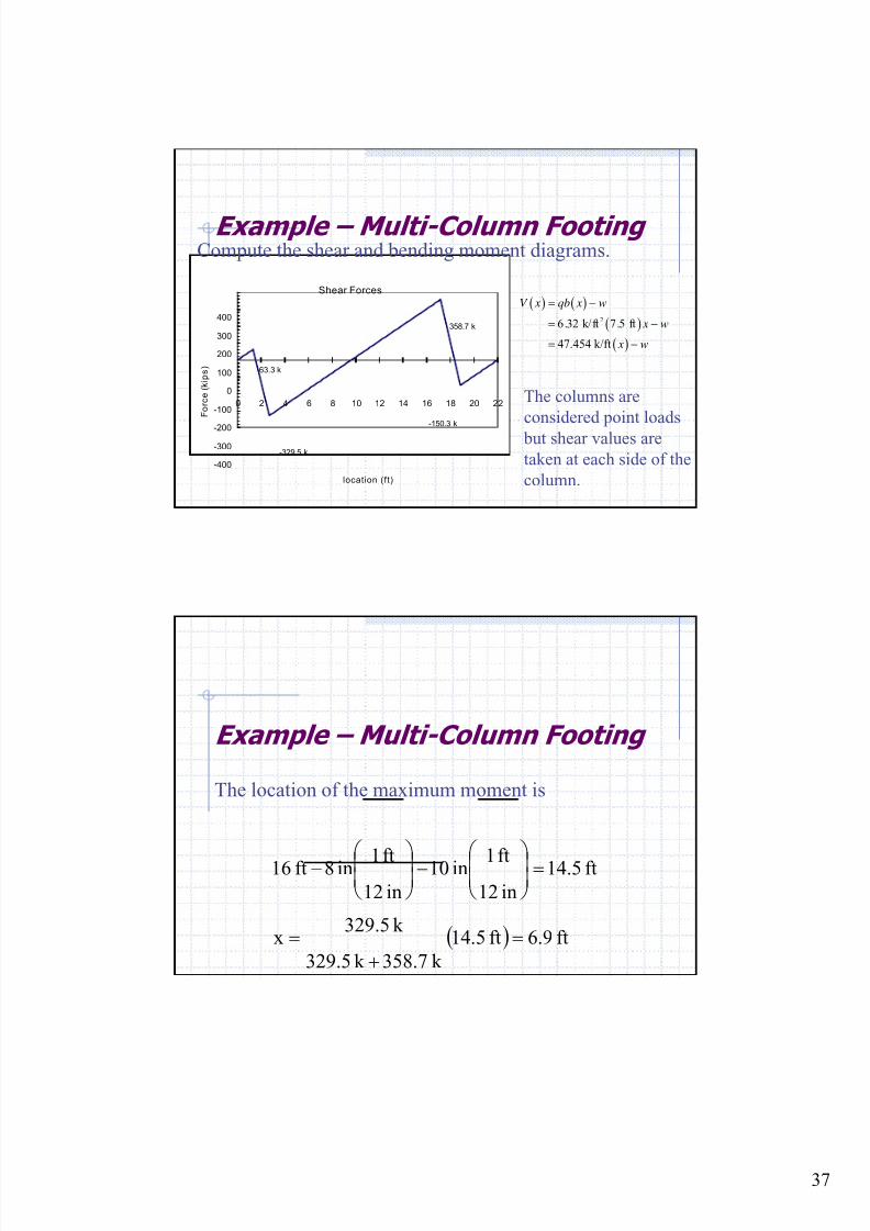
Example – Multi-Column FootingCompute the shear and bending moment diagrams.
Shear Forces
-400
-300
-200
-100
0
100
200
300
400
0 2 4 6 8 10 12 14 16 18 20 22
location (ft)
F o r c e (
k i p s )
63.3 k
-329.5 k
358.7 k
-150.3 k
The columns are
considered point loads
but shear values are
taken at each side of the
column.
( ) ( )
( )
( )
26.32 k/ft 7.5 ft
47.454 k/ft
V x qb x w
x w
x w
= −
= −
= −
Example – Multi-Column Footing
The location of the maximum moment is
( ) ft9.6ft5.14
k 7.358k 329.5
k 329.5x
ft5.14in12ft1in10
in12ft1in8ft16
=+
=
=⎟⎟ ⎠
⎞⎜⎜⎝
⎛ −⎟⎟
⎠
⎞⎜⎜⎝
⎛ −
8/18/2019 Footing design and analysis
http://slidepdf.com/reader/full/footing-design-and-analysis 38/53
38
Example – Multi-Column Footing
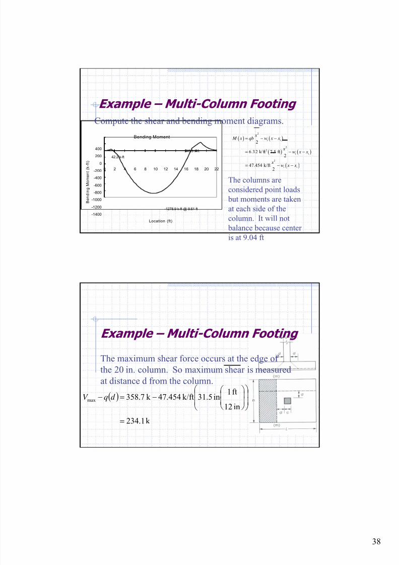
Compute the shear and bending moment diagrams.
The columns are
considered point loads
but moments are takenat each side of the
column. It will not
balance because center
is at 9.04 ft
Bending Moment
-1400
-1200
-1000
-800
-600
-400
-200
0
200
400
0 2 4 6 8 10 12 14 16 18 20 22
Location (ft)
B e n
d i n g M o m e n t ( k - f t )
-1278.9 k-ft @ 9.61 ft
42.2 k-ft
249.9 k-ft
( ) ( )
( ) ( )
( )
2
i i
22
i i
2
i i
2
6.32 k/ft 7.5 ft2
47.454 k/ft2
x M x qb w x x
xw x x
xw x x
= − −
= − −
= − −
Example – Multi-Column Footing
The maximum shear force occurs at the edge of
the 20 in. column. So maximum shear is measured
at distance d from the column.
( )
k 1.234
in12ft1in31.5k/ft454.47k7.358max
=
⎟⎟ ⎠
⎞
⎜⎜⎝
⎛
⎟⎟ ⎠
⎞⎜⎜⎝
⎛ −=− d qV
8/18/2019 Footing design and analysis
http://slidepdf.com/reader/full/footing-design-and-analysis 39/53
39
Example – Multi-Column Footing
The depth of the footing can be calculated by using
one-way shear
in.2.24
ft1
in12ft.57400020.85
k 1
lb1000k 34.12
2 c
u =
⎟
⎟
⎠
⎞
⎜
⎜
⎝
⎛
⎟
⎟
⎠
⎞
⎜
⎜
⎝
⎛
⎟
⎟
⎠
⎞
⎜
⎜
⎝
⎛
⎟⎟
⎠
⎞⎜⎜⎝
⎛
==b f
V d
φ
The footing is 31.5 in. > 24.2 in. so it will work.
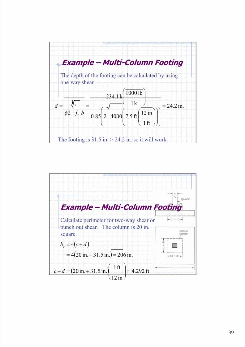
Example – Multi-Column Footing
Calculate perimeter for two-way shear or
punch out shear. The column is 20 in.
square.
( )( )
( ) ft292.4
in12
ft1in.5.31in.02
in.206in.5.31in.024
4o
=⎟⎟
⎠
⎞⎜⎜⎝
⎛ +=+
=+=+=
d c
d cb
8/18/2019 Footing design and analysis
http://slidepdf.com/reader/full/footing-design-and-analysis 40/53
40
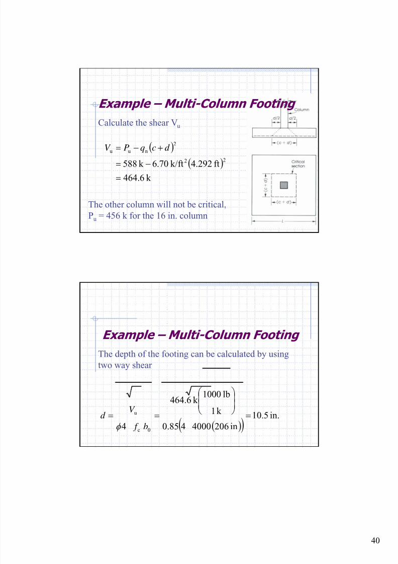
Example – Multi-Column Footing
Calculate the shear Vu
( )
( )
k 6.464
ft292.4k/ft6.70k58822
2
nuu
=
−=
+−= d cqPV
The other column will not be critical,
Pu = 456 k for the 16 in. column
Example – Multi-Column Footing
The depth of the footing can be calculated by using
two way shear
( )( )in.5.10
in206400040.85
k 1
lb1000k 64.64
4 0c
u =⎟⎟
⎠ ⎞⎜⎜
⎝ ⎛
==b f
V d
φ
8/18/2019 Footing design and analysis
http://slidepdf.com/reader/full/footing-design-and-analysis 41/53
41
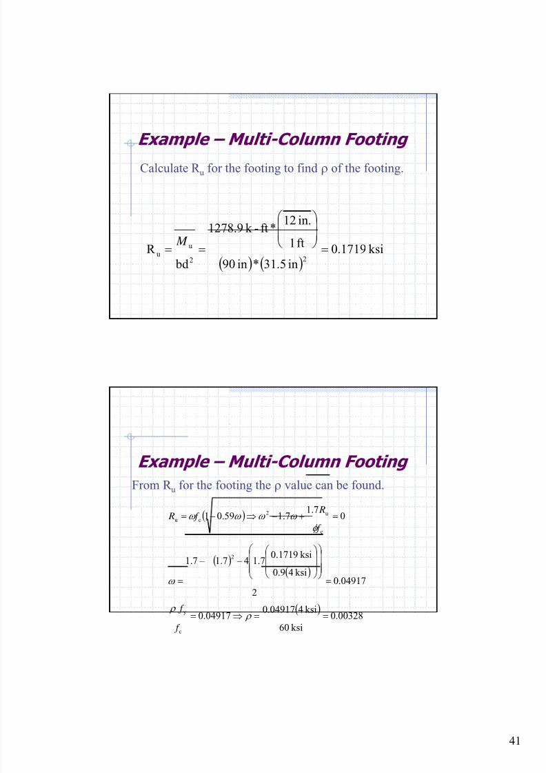
Example – Multi-Column Footing
Calculate R u for the footing to find ρ of the footing.
( ) ( )
ksi1719.0
in5.31*in90
ft1
in.12*ft-k 278.91
bd
R 22
uu =
⎟⎟
⎠
⎞⎜⎜⎝
⎛
== M
Example – Multi-Column Footing
From R u for the footing the ρ value can be found.
( )
( )( )
( )00328.0
ksi60
ksi404917.004917.0
04917.0
2
ksi49.0
ksi1719.07.147.17.1
07.1
7.159.01
c
y
2
c
u2
cu
==⇒=
=⎟⎟⎟
⎠
⎞
⎜⎜⎜
⎝
⎛
⎟⎟
⎠
⎞
⎜⎜
⎝
⎛ −−
=
=+−⇒−=
ρ ρ
ω
φ
ω ω ω ω
f
f
f
R f R
8/18/2019 Footing design and analysis
http://slidepdf.com/reader/full/footing-design-and-analysis 42/53
42
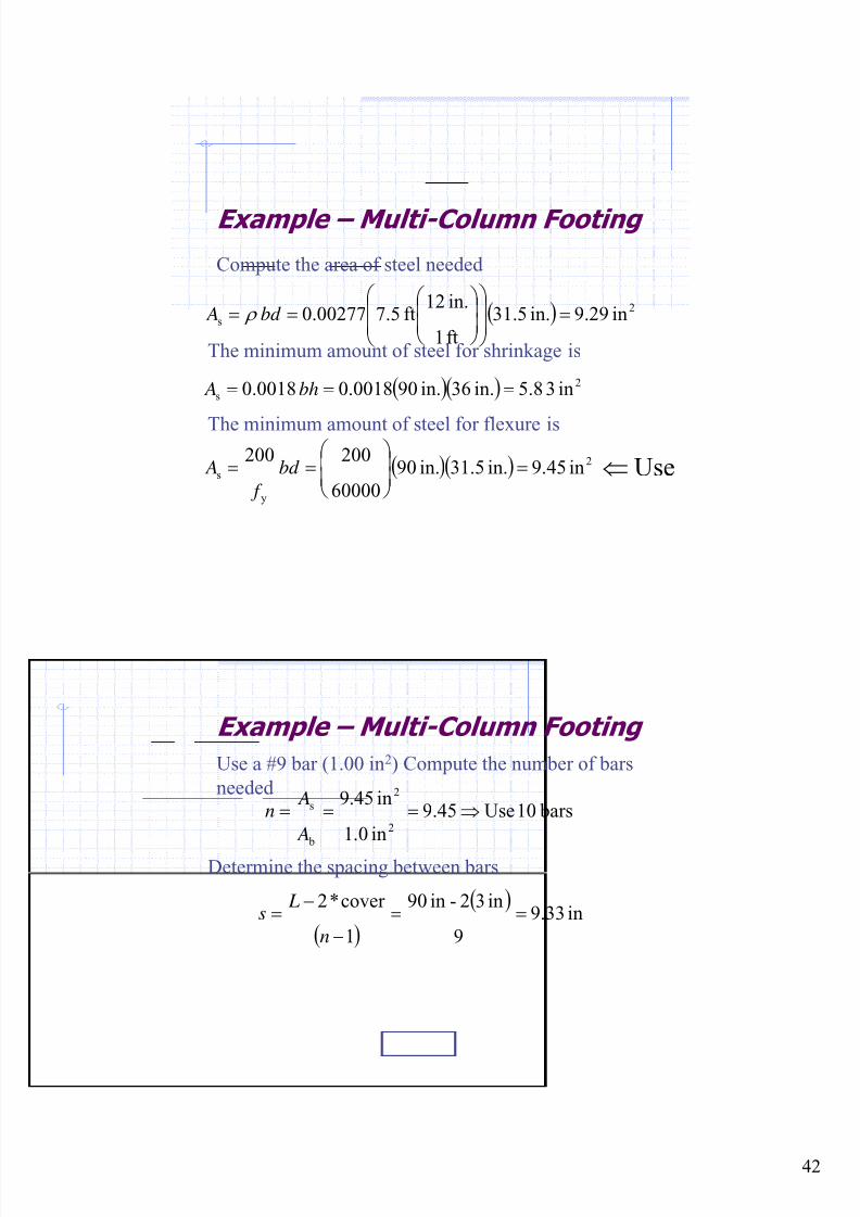
Example – Multi-Column Footing
Compute the area of steel needed
( ) 2
s in29.9in.5.31
ft1
in.12ft5.700277.0 =
⎟⎟
⎠
⎞
⎜⎜
⎝
⎛
⎟⎟ ⎠
⎞⎜⎜⎝
⎛ == bd A ρ
The minimum amount of steel for shrinkage is
( )( ) 2
s in38.5in.63in.900018.00018.0 === bh A
The minimum amount of steel for flexure is
( )( ) 2
y
s in45.9in.1.53in.90
60000
200
200=⎟
⎟ ⎠
⎞⎜⎜⎝
⎛ == bd
f
A Use⇐
Example – Multi-Column Footing
Use a #9 bar (1.00 in2) Compute the number of bars
needed bars10Use45.9
in0.1
in45.9
2
2
b
s ⇒=== A
An
Determine the spacing between bars
( )
( )in33.9
9
in32-in90
1
cover *2==
−
−=
n
Ls
8/18/2019 Footing design and analysis
http://slidepdf.com/reader/full/footing-design-and-analysis 43/53
43
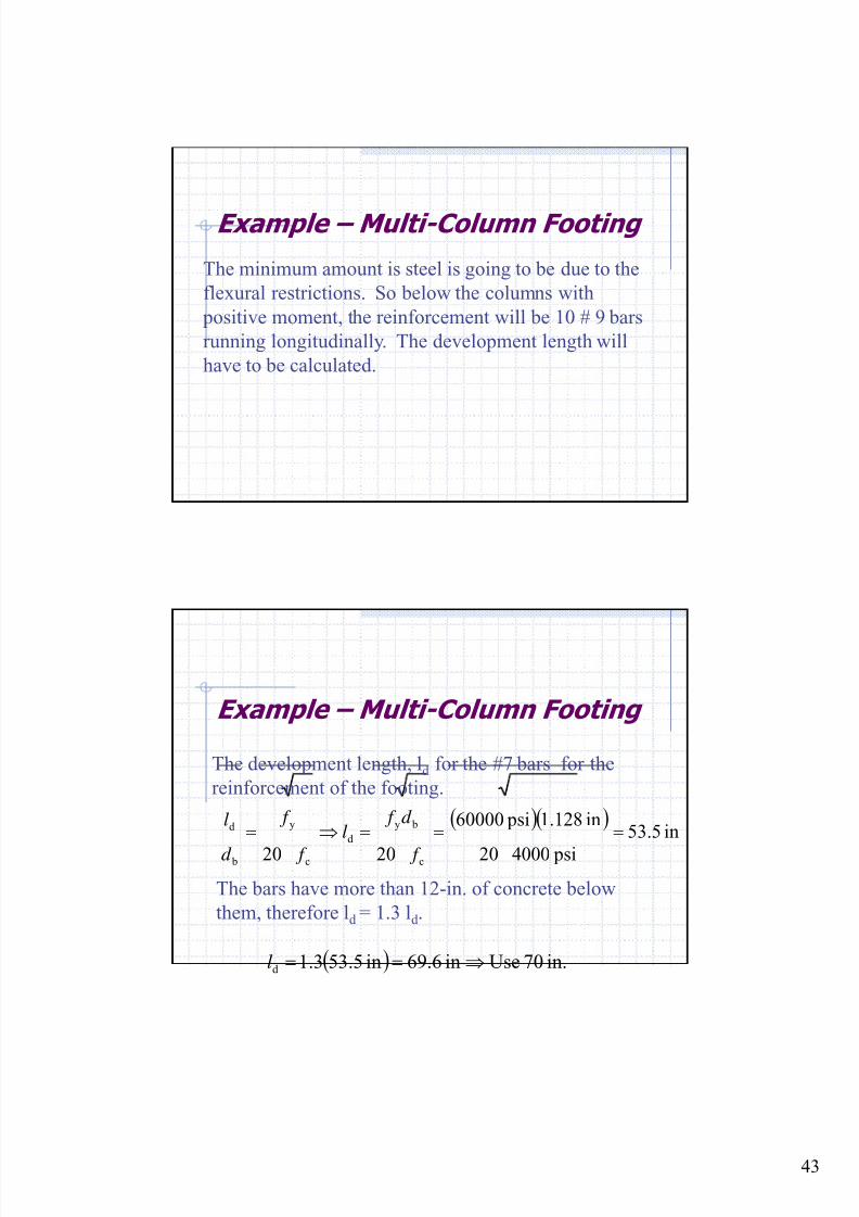
Example – Multi-Column Footing
The minimum amount is steel is going to be due to the
flexural restrictions. So below the columns with
positive moment, the reinforcement will be 10 # 9 bars
running longitudinally. The development length will
have to be calculated.
Example – Multi-Column Footing
The development length, ld for the #7 bars for the
reinforcement of the footing.
( )( )in5.53
psi400020
in.1281 psi60000
2020 c
by
d
c
y
b
d ===⇒=
f
d f l
f
f
d
l
The bars have more than 12-in. of concrete below
them, therefore ld = 1.3 ld .
( ) in.70Usein6.69in3.553.1d ⇒==l
8/18/2019 Footing design and analysis
http://slidepdf.com/reader/full/footing-design-and-analysis 44/53
44
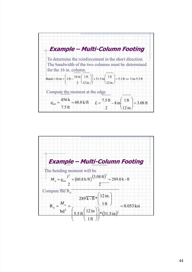
Example – Multi-Column Footing
To determine the reinforcement in the short direction.
The bandwidth of the two columns must be determined
for the 16 in. column.
ft5.5 Useft3.5
in.12
ft1in5.31
in.12
ft1
2
in16 ft2in16Band ⇒=⎟
⎟ ⎠
⎞⎜⎜⎝
⎛ +
⎟⎟
⎠
⎞
⎜⎜
⎝
⎛
⎟⎟ ⎠
⎞⎜⎜⎝
⎛ −+=
Compute the moment at the edge
k/ft8.60
ft7.5
k 456net ==q ft08.3
in12
ft1in8
2
ft5.7=⎟
⎟ ⎠
⎞⎜⎜⎝
⎛ −= L
Example – Multi-Column Footing
The bending moment will be
Compute the R u
( )( )
ft-k 0.289
2
ft3.08k/ft8.60
2
22
netu === l
q M
( )
ksi053.0
in5.31*
ft1
in12ft5.5
ft1
in.12*ft-k 289
bd
R
22
uu =
⎟⎟
⎠
⎞
⎜⎜
⎝
⎛
⎟⎟
⎠
⎞⎜⎜⎝
⎛
⎟⎟
⎠
⎞⎜⎜⎝
⎛
== M
8/18/2019 Footing design and analysis
http://slidepdf.com/reader/full/footing-design-and-analysis 45/53
45
Example – Multi-Column Footing
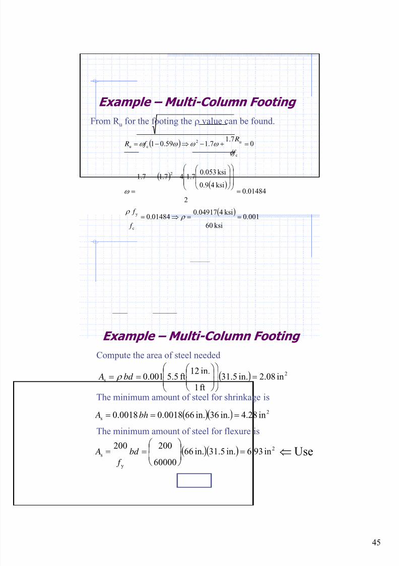
From R u for the footing the ρ value can be found.
( )
( )( )
( )001.0
ksi60
ksi404917.001484.0
01484.0
2
ksi49.0
ksi053.07.147.17.1
07.1
7.159.01
c
y
2
c
u2
cu
==⇒=
=⎟⎟⎟
⎠
⎞
⎜⎜⎜
⎝
⎛
⎟⎟
⎠
⎞
⎜⎜
⎝
⎛ −−
=
=+−⇒−=
ρ ρ
ω
φ
ω ω ω ω
f
f
f
R f R
Example – Multi-Column Footing
Compute the area of steel needed
( ) 2
s in08.2in.5.31
ft1
in.12ft5.5001.0 =
⎟⎟
⎠
⎞
⎜⎜
⎝
⎛
⎟⎟ ⎠
⎞⎜⎜⎝
⎛ == bd A ρ
The minimum amount of steel for shrinkage is
( )( ) 2
s in28.4in.63in.660018.00018.0 === bh A
The minimum amount of steel for flexure is
( )( ) 2
y
s in93.6in.1.53in.66
60000
200
200=⎟
⎟ ⎠
⎞⎜⎜⎝
⎛ == bd
f
A Use⇐
8/18/2019 Footing design and analysis
http://slidepdf.com/reader/full/footing-design-and-analysis 46/53
46
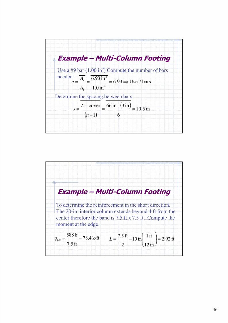
Example – Multi-Column Footing
Use a #9 bar (1.00 in2) Compute the number of bars
needed bars7Use93.6
in0.1
in93.6
2
2
b
s ⇒=== A
An
Determine the spacing between bars
( )
( )in5.10
6
in3-in66
1
cover ==
−
−=
n
Ls
Example – Multi-Column Footing
To determine the reinforcement in the short direction.
The 20-in. interior column extends beyond 4 ft from the
center therefore the band is 7.5 ft x 7.5 ft. Compute the
moment at the edge
k/ft4.78
ft7.5
k 885net ==q ft92.2
in12
ft1in10
2
ft5.7=⎟
⎟ ⎠
⎞⎜⎜⎝
⎛ −= L
8/18/2019 Footing design and analysis
http://slidepdf.com/reader/full/footing-design-and-analysis 47/53
47
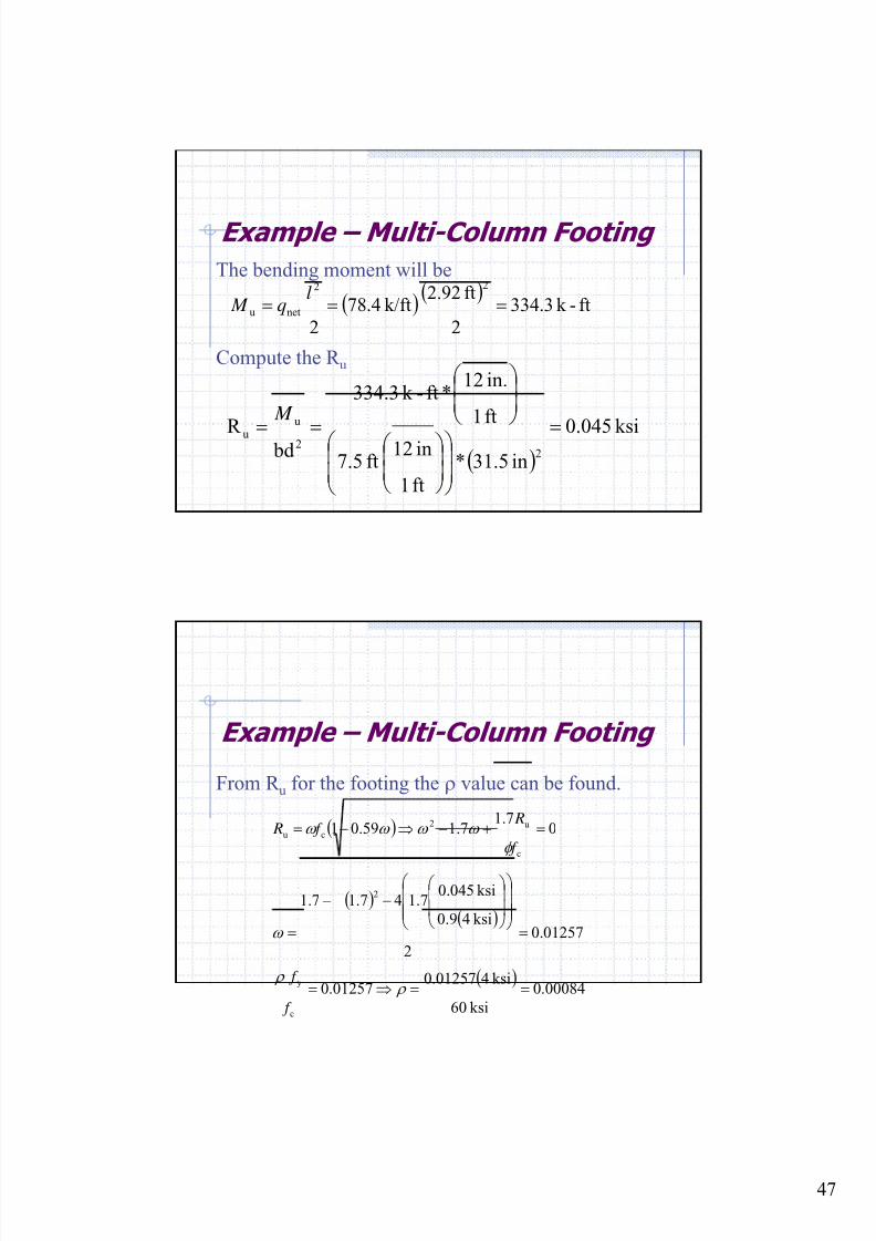
Example – Multi-Column Footing
The bending moment will be
Compute the R u
( )( )
ft-k 3.334
2
ft2.92k/ft4.78
2
22
netu === l
q M
( )ksi045.0
in5.31*
ft1
in12ft7.5
ft1
in.12*ft-k 334.3
bd R 2
2
u
u =⎟⎟
⎠
⎞⎜⎜
⎝
⎛ ⎟⎟
⎠
⎞⎜⎜⎝
⎛
⎟⎟
⎠
⎞⎜⎜⎝
⎛
==
M
Example – Multi-Column Footing
From R u for the footing the ρ value can be found.
( )
( )( )
( )00084.0
ksi60
ksi401257.001257.0
01257.0
2
ksi49.0
ksi045.07.147.17.1
07.1
7.159.01
c
y
2
c
u2
cu
==⇒=
=⎟⎟⎟
⎠
⎞
⎜⎜⎜
⎝
⎛
⎟⎟
⎠
⎞
⎜⎜
⎝
⎛ −−
=
=+−⇒−=
ρ ρ
ω
φ
ω ω ω ω
f
f
f
R f R
8/18/2019 Footing design and analysis
http://slidepdf.com/reader/full/footing-design-and-analysis 48/53
48
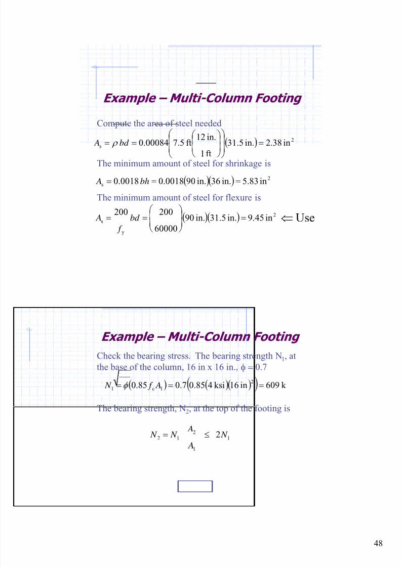
Example – Multi-Column Footing
Compute the area of steel needed
( ) 2
s in38.2in.5.31
ft1
in.12ft5.700084.0 =
⎟⎟
⎠
⎞
⎜⎜
⎝
⎛
⎟⎟ ⎠
⎞⎜⎜⎝
⎛ == bd A ρ
The minimum amount of steel for shrinkage is
( )( ) 2
s in83.5in.63in.090018.00018.0 === bh A
The minimum amount of steel for flexure is
( )( ) 2
y
s in45.9in.1.53in.09
60000
200
200=⎟
⎟ ⎠
⎞⎜⎜⎝
⎛ == bd
f
A Use⇐
Example – Multi-Column Footing
Check the bearing stress. The bearing strength N1, at
the base of the column, 16 in x 16 in., φ = 0.7
( ) ( )( )( ) k 609in16ksi485.07.085.02
1c1 === A f N φ
The bearing strength, N2, at the top of the footing is
1
1
212 2 N
A
A N N ≤=
8/18/2019 Footing design and analysis
http://slidepdf.com/reader/full/footing-design-and-analysis 49/53
49
Example – Multi-Column Footing
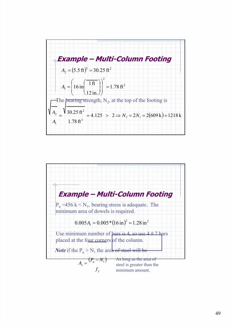
The bearing strength, N2, at the top of the footing is
( ) k 1218k 096222 4.125ft78.1ft30.25 12
2
2
1
2 ===⇒>== N N A A
( )
2
2
1
22
2
ft78.1
in.12
ft1in16
ft25.30ft.55
=⎟⎟
⎠
⎞
⎜⎜
⎝
⎛
⎟⎟ ⎠
⎞⎜⎜⎝
⎛ =
==
A
A
Example – Multi-Column Footing
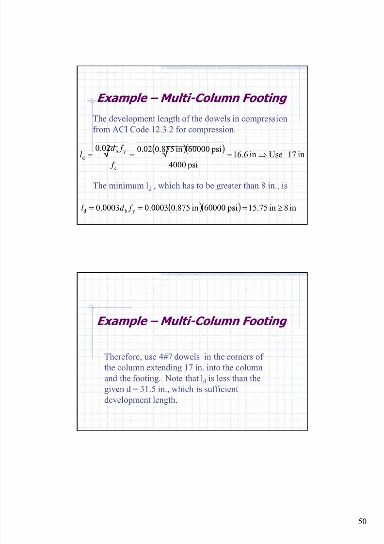
Pu =456 k < N1, bearing stress is adequate. The
minimum area of dowels is required.
( ) 22
1 in28.1in16*005.0005.0 == A
Use minimum number of bars is 4, so use 4 # 7 bars
placed at the four corners of the column.
Note if the Pu > N1 the area of steel will be
( )
y
1us
f
N P A
−=
As long as the area of
steel is greater than the
minimum amount.
8/18/2019 Footing design and analysis
http://slidepdf.com/reader/full/footing-design-and-analysis 50/53
50
Example – Multi-Column Footing
The development length of the dowels in compression
from ACI Code 12.3.2 for compression.
( )( )in17 Usein6.16
psi4000
psi60000in.875002.002.0
c
y b
d ⇒=== f
f d l
The minimum ld , which has to be greater than 8 in., is
( )( ) in8in75.15 psi60000in.87500003.00003.0 y bd ≥=== f d l
Example – Multi-Column Footing
Therefore, use 4#7 dowels in the corners of
the column extending 17 in. into the column
and the footing. Note that ld is less than thegiven d = 31.5 in., which is sufficient
development length.
8/18/2019 Footing design and analysis
http://slidepdf.com/reader/full/footing-design-and-analysis 51/53
51
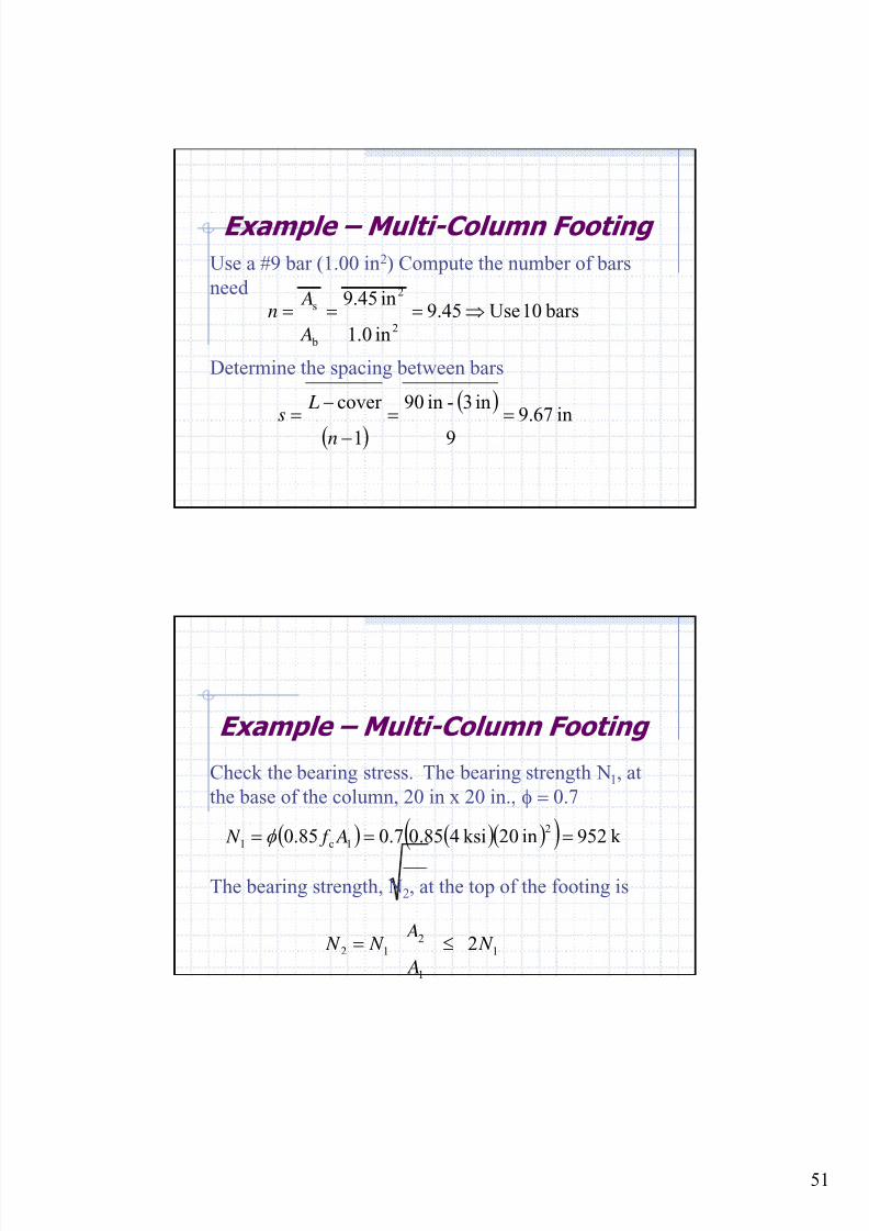
Example – Multi-Column Footing
Use a #9 bar (1.00 in2) Compute the number of bars
need bars10Use45.9
in0.1
in45.9
2
2
b
s ⇒=== A
An
Determine the spacing between bars
( )
( )in67.9
9
in3-in90
1
cover ==
−
−=
n
Ls
Example – Multi-Column Footing
Check the bearing stress. The bearing strength N1, at
the base of the column, 20 in x 20 in., φ = 0.7
( ) ( )( )( ) k 952in02ksi485.07.085.02
1c1 === A f N φ
The bearing strength, N2, at the top of the footing is
1
1
212 2 N
A
A N N ≤=
8/18/2019 Footing design and analysis
http://slidepdf.com/reader/full/footing-design-and-analysis 52/53
52
Example – Multi-Column Footing
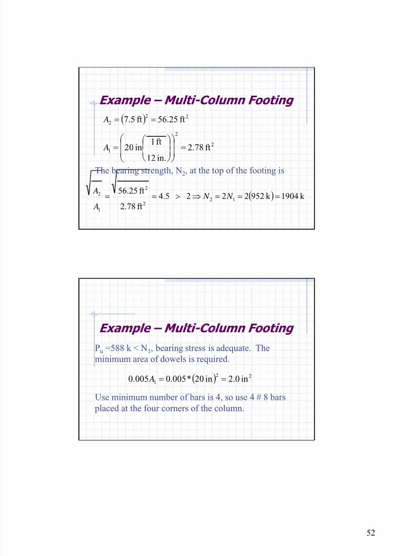
The bearing strength, N2, at the top of the footing is
( ) k 1904k 952222 4.5ft78.2ft56.25 12
2
2
1
2 ===⇒>== N N A A
( )
2
2
1
22
2
ft78.2
in.12
ft1in02
ft25.56ft.57
=⎟⎟
⎠
⎞
⎜⎜
⎝
⎛
⎟⎟ ⎠
⎞⎜⎜⎝
⎛ =
==
A
A
Example – Multi-Column Footing
Pu =588 k < N1, bearing stress is adequate. The
minimum area of dowels is required.
( ) 22
1 in0.2in02*005.0005.0 == A
Use minimum number of bars is 4, so use 4 # 8 bars
placed at the four corners of the column.
8/18/2019 Footing design and analysis
http://slidepdf.com/reader/full/footing-design-and-analysis 53/53
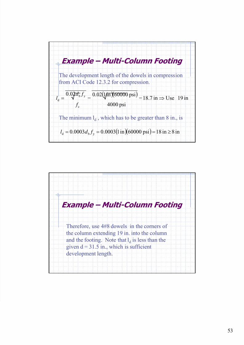
Example – Multi-Column Footing
The development length of the dowels in compression
from ACI Code 12.3.2 for compression.
( )( )in19 Usein7.18
psi4000
psi60000in102.002.0
c
y b
d ⇒=== f
f d l
The minimum ld , which has to be greater than 8 in., is
( )( ) in8in18 psi60000in10003.00003.0 y bd ≥=== f d l
Example – Multi-Column Footing
Therefore, use 4#8 dowels in the corners of
the column extending 19 in. into the column
and the footing. Note that ld is less than thegiven d = 31.5 in., which is sufficient
development length.