Embed Size (px)
DESCRIPTION
FM 3-05.211 Special Forces Military Free-Fall Operations
Citation preview
FM 3-05.211 (FM 31-19) MCWP 3-15.6
NAVSEA SS400-AG-MMO-010 AFMAN 11-411(I)
Special Forces Military Free-Fall
Operations
APRIL 2005
DISTRIBUTION RESTRICTION: Distribution authorized to U.S. Government agencies and their contractors only to protect technical or operational information from automatic dissemination under the International Exchange Program or
by other means. This determination was made on 15 December 2004. Other requests for this document must be referred to Commander, United States Army John F. Kennedy Special Warfare
Center and School, ATTN: AOJK-DT-SFA, Fort Bragg, NC 28310-5000.
DESTRUCTION NOTICE: Destroy by any method that will prevent disclosure of contents or reconstruction of the document.
Headquarters, Department of the Army
Foreword This publication has been prepared under our direction for use by our respective commands and other commands as appropriate.
JAMES W. PARKER RONALD E. KEYS Major General, USA Lieutenant General, USAF Commanding Deputy Chief of Staff U.S. Army John F. Kennedy Special Air & Space Operations Warfare Center and School
JOHN M. KELLY J. N. MATTIS Rear Admiral, USN Lieutenant General, USMC Program Executive Officer Commanding General Expeditionary Warfare Marine Corps Combat
Development Command
i
*FM 3-05.211 (FM 31-19) MCWP 3-15.6
NAVSEA SS400-AG-MMO-010 AFMAN 11-411(I)
Field Manual Headquarters No. 3-05.211 Department of the Army Washington, DC, 6 April 2005
Special Forces Military Free-Fall Operations
Contents Page
PREFACE .................................................................................................................. v Chapter 1 MILITARY FREE-FALL PARACHUTE OPERATIONS ..........................................1-1
Characteristics .........................................................................................................1-1 Planning Considerations ..........................................................................................1-2 Phases of Military Free-Fall Operations ..................................................................1-5
Chapter 2 MC-4 RAM-AIR PARACHUTE SYSTEM ................................................................2-1 MC-4 Ram-Air Parachute System Components ......................................................2-1 Donning and Recovering the MC-4 Ram-Air Parachute System ..........................2-15
Chapter 3 AUTOMATIC RIPCORD RELEASE .......................................................................3-1 Automatic Ripcord Release Activation Setting and Operation ................................3-1 FF-2 Automatic Ripcord Release ............................................................................3-1
DISTRIBUTION RESTRICTION: Distribution authorized to U.S. Government agencies and their contractors only to protect technical or operational information from automatic dissemination under the International Exchange Program or by other means. This determination was made on 15 December 2004. Other requests for this document must be referred to Commander, United States Army John F. Kennedy Special Warfare Center and School, ATTN: AOJK-DT-SFA, Fort Bragg, NC 28310-5000.
DESTRUCTION NOTICE: Destroy by any method that will prevent disclosure of contents or reconstruction of the document.
Marine Corps distribution: PCN 14300004300
*This publication supersedes FM 31-19, 1 October 1999.
FM 3-05.211
ii FM 3-05.211/MCWP 3-15.6/NAVSEA SS400-AG-MMO-010/AFMAN 11-411(I) 6 April 2005
Page
AR2 Automatic Ripcord Release, M451 ................................................................. 3-6 AR2 Barometric Calculator, Model 466-001 ........................................................... 3-9 Sentinel MK 2100 .................................................................................................. 3-20 Military CYPRES ................................................................................................... 3-22
Chapter 4 USE OF OXYGEN IN SUPPORT OF MILITARY FREE-FALL OPERATIONS ..... 4-1 Physiological Effects of High-Altitude Military Free-Fall Operations ....................... 4-1 Oxygen Forms ......................................................................................................... 4-4 Oxygen Requirements ............................................................................................ 4-5 Oxygen Life-Support Equipment ............................................................................. 4-7 The “PRICE” Check .............................................................................................. 4-19 Oxygen Safety Personnel and Preflight Checks ................................................... 4-19 Oxygen Handling and Safety ................................................................................ 4-24
Chapter 5 EQUIPMENT AND WEAPON RIGGING PROCEDURES ..................................... 5-1 Equipment and Weapon Packing Considerations .................................................. 5-1 Parachutist and Parachute Load Limitations .......................................................... 5-1 Hook-Pile Tape (Velcro) Lowering Line Assembly ................................................. 5-3 Combat Packs and Other Equipment Containers ................................................... 5-5 Parachutist Drop Bag ............................................................................................ 5-31 Weapon-Rigging Procedures ................................................................................ 5-36 Life Preservers ...................................................................................................... 5-50
Chapter 6 AIRCRAFT PROCEDURE SIGNALS AND JUMP COMMANDS .......................... 6-1 Aircraft Procedure Signals ...................................................................................... 6-1 Jump Commands .................................................................................................... 6-7
Chapter 7 BODY STABILIZATION ......................................................................................... 7-1 Tabletop Body Stabilization Training ...................................................................... 7-1 Recovery From Instability ....................................................................................... 7-3
Chapter 8 RAM-AIR PARACHUTE FLIGHT CHARACTERISTICS AND CANOPY CONTROL ..................................................................................... 8-1 Ram-Air Parachute Characteristics ......................................................................... 8-1 Ram-Air Parachute Deployment Sequence ............................................................ 8-3 Ram-Air Parachute Theory of Flight ....................................................................... 8-7 Ram-Air Parachute Flight Characteristics ............................................................... 8-8 Canopy Control ....................................................................................................... 8-9 Turbulence ............................................................................................................ 8-19
FM 3-05.211
6 April 2005 FM 3-05.211/MCWP 3-15.6/NAVSEA SS400-AG-MMO-010/AFMAN 11-411(I) iii
Page
Land and Sea Breezes ..........................................................................................8-20 Valley and Mountain Breezes ................................................................................8-21
Chapter 9 EMERGENCY PROCEDURES FOR MILITARY FREE-FALL OPERATIONS ......9-1 Refresher Training ...................................................................................................9-1 Emergency Measures ..............................................................................................9-1
Chapter 10 HIGH-ALTITUDE HIGH-OPENING AND LIMITED-VISIBILITY OPERATIONS .......................................................................................................10-1 Techniques and Requirements .............................................................................10-1 Special Equipment .................................................................................................10-2 Free-Fall Delays ....................................................................................................10-3 Parachute Jump Phases .......................................................................................10-3 Limited-Visibility Operations ..................................................................................10-4
Chapter 11 MILITARY FREE-FALL DROP ZONE OPERATIONS .........................................11-1 Responsibilities ......................................................................................................11-1 Drop Zone Selection Criteria .................................................................................11-1 Drop Zone Surveys ................................................................................................11-2 Drop Zone Personnel Qualifications and Responsibilities ....................................11-3 Military Free-Fall Drop Zone Markings ..................................................................11-6 High-Altitude Release Point and Military Free-Fall Drop Zone Detection .............11-6 Aircraft or High-Altitude High-Opening Team Identification ..................................11-7 Authentication System ...........................................................................................11-7
Chapter 12 DELIBERATE WATER MILITARY FREE-FALL OPERATIONS .........................12-1 Additional Support Requirements ..........................................................................12-1 Parachutist Requirements .....................................................................................12-2 Equipment Requirements ......................................................................................12-2 Drop Zone Requirements and Markings ...............................................................12-4 Parachutist Procedures for Water Jumps ..............................................................12-4 Drop Zone Procedures for Pickup of Parachutists and Equipment .......................12-5 Night Water Parachute Operations .......................................................................12-6 Water Jumps With Combat Equipment .................................................................12-6
Chapter 13 JUMPMASTER RESPONSIBILITIES AND CURRENCY QUALIFICATIONS .....13-1 Responsibilities ......................................................................................................13-1 Qualifications .........................................................................................................13-2 Cardinal Rules .......................................................................................................13-2 Currency and Requalification Requirements .........................................................13-3
FM 3-05.211
iv FM 3-05.211/MCWP 3-15.6/NAVSEA SS400-AG-MMO-010/AFMAN 11-411(I) 6 April 2005
Page
Appendix A MILITARY FREE-FALL CRITICAL TASK LISTS ..................................................A-1 Appendix B MILITARY FREE-FALL PARACHUTIST QUALIFICATION
AND REFRESHER TRAINING REQUIREMENTS ................................................B-1 Appendix C RECOMMENDED MILITARY FREE-FALL TRAINING PROGRAMS .................. C-1 Appendix D SUGGESTED MILITARY FREE-FALL SUSTAINED AIRBORNE TRAINING ..... D-1 Appendix E SAMPLE ACCIDENT REPORT .............................................................................E-1 Appendix F HIGH-ALTITUDE RELEASE POINT CALCULATION ...........................................F-1 Appendix G JUMPMASTER PERSONNEL INSPECTION ....................................................... G-1 Appendix H SAMPLE AIRCRAFT INSPECTION CHECKLIST ................................................ H-1 Appendix I JUMPMASTER AIRCREW BRIEFING CHECKLIST .............................................. I-1 GLOSSARY ................................................................................................Glossary-1 BIBLIOGRAPHY ................................................................................... Bibliography-1 INDEX .............................................................................................................. Index-1
FM 3-05.211
6 April 2005 FM 3-05.211/MCWP 3-15.6/NAVSEA SS400-AG-MMO-010/AFMAN 11-411(I) v
Preface Department of Defense (DOD) Directive 5100.1, Functions of the Department of Defense and Its Major Components, page 17, paragraph 6.6.1.2.3.2, has designated the United States Army as the proponent for military parachute operations.
Department of the Army memorandum, Subject: Army Military Free-Fall Proponency, dated 23 September 1998, establishes USASOC as the proponent for military free-fall (MFF) training, operations, equipment, and doctrine.
United States Special Operations Command (USSOCOM) Directive 10-1, Organization and Functions, Terms of Reference for Component Commanders, Appendix A, page A-5, paragraph R, establishes Commander, USASOC, as the proponent for MFF training, doctrine, safety, equipment, and interoperability for USSOCOM Active and Reserve forces.
The Commander, United States Army John F. Kennedy Special Warfare Center and School (USAJFKSWCS), Fort Bragg, North Carolina, is USASOC’s executive agent for MFF training and doctrine.
This field manual (FM) presents a series of concise, proven techniques and guidelines that are essential to safe, successful MFF operations. The techniques and guidelines prescribed herein are generic in nature and represent the safest and most effective methodologies available for executing MFF operations.
This FM applies to Army and USSOCOM MFF-capable units. USSOCOM components are authorized to produce publications to supplement this manual to clarify and amplify the procedures of this manual and Service publications. Commanders can request waivers from their Service or component commanders to meet specific operational requirements when methodologies contained in this manual impede mission accomplishment.
When Service publications and USSOCOM publications conflict, USSOCOM publications will take precedence during operations in which USSOCOM units are the supported unit. When conducting Service-pure MFF operations, Services will use their applicable regulations and standing operating procedures (SOPs).
The proponent and preparing agency of this publication is USAJFKSWCS. Reviewers and users of this publication should submit comments and recommended changes on Department of the Army Form 2028 to Commander, USAJFKSWCS, ATTN: AOJK-DT-SFA, Fort Bragg, NC 28310-5000.
This FM implements Standardization Agreement (STANAG) 3570, Drop Zones and Extraction Zones—Criteria and Markings, 26 March 1986.
Unless this publication states otherwise, masculine nouns and pronouns do not refer exclusively to men.

This page intentionally left blank.
FM 3-05.211
6 April 2005 FM 3-05.211/MCWP 3-15.6/NAVSEA SS400-AG-MMO-010/AFMAN 11-411(I) 1-1
Chapter 1
Military Free-Fall Parachute Operations Special operations forces (SOF) must conduct a detailed mission analysis to determine an appropriate method of infiltration. MFF operations are one of the many options available to a commander to infiltrate personnel into a designated area of operations (AO). MFF operations are ideally suited for, but not limited to, the infiltration of operational elements, pilot teams, pathfinder elements, special tactics team (STT) assets, and personnel replacements conducting various missions across the operational continuum. A thorough understanding of all the factors impacting MFF operations is essential due to the inherently high levels of risk associated with MFF operations. The objective of this chapter is to familiarize the reader with MFF operations and to outline the planning considerations needed to successfully execute MFF operations.
CHARACTERISTICS 1-1. MFF parachute operations are used when enemy air defense systems, terrain restrictions, or politically sensitive environments prevent low altitude penetration or when mission needs require a clandestine insertion. MFF parachute infiltrations are conducted using the Ram-Air Parachute System (RAPS), which is a high-performance gliding system. The RAPS is a highly maneuverable parachute that has forward air speeds of 20 to 30 miles per hour (mph). The glide capability of the RAPS provides commanders the means to conduct standoff infiltrations of designated areas without having to physically fly over the target area. This process allows commanders to keep high-value air assets outside the detection and threat ranges of enemy air defense systems or politically sensitive areas.
1-2. MFF parachuting allows SOF personnel to deploy their parachutes at a predetermined altitude, assemble in the air, navigate under canopy, and land safely together as a tactical unit ready to execute their mission. Although free-fall parachuting can produce highly accurate landings, it is primarily a means of entering a designated impact area within the objective area. The following are two basic types of MFF operations:
• High-altitude low-opening (HALO) operations are jumps made with an exit altitude of up to 35,000 feet mean sea level (MSL) and a parachute deployment altitude at or below 6,000 feet above ground level (AGL). HALO infiltrations are the preferred MFF method of infiltration when the enemy air defense posture is not a viable threat to the infiltration platform. HALO infiltrations require the infiltration platform to fly within several kilometers of the drop zone (DZ).
• High-altitude high-opening (HAHO) operations are standoff infiltration jumps made with an exit altitude of up to 35,000 feet MSL and a

FM 3-05.211
1-2 FM 3-05.211/MCWP 3-15.6/NAVSEA SS400-AG-MMO-010/AFMAN 11-411(I) 6 April 2005
parachute deployment altitude at or above 6,000 feet AGL. HAHO infiltrations are the preferred method of infiltration when the enemy air defense threat is viable or when a low-signature infiltration is required. Standoff HAHO infiltrations provide commanders a means to drop MFF parachutists outside the air defense umbrella, where they can navigate undetected under canopy to the DZ or objective area.
1-3. Personnel involved in MFF operations require extensive knowledge of meteorology and navigation. They must be able to conduct realistic premission training, gather information, plan, rehearse, and use the appropriate MFF infiltration technique to accomplish their assigned mission. (Appendix A includes the critical task lists for the MFF basic, advanced, and jumpmaster courses.) Tandem operations, however, must be conducted in accordance with (IAW) current doctrine and approved tactics, techniques, and procedures (TTP).
1-4. When used correctly, MFF infiltrations give commanders another means to move SOF and influence the battlefield. The skills and techniques used in MFF operations are equally applicable to all SF core tasks, especially direct action (DA), special reconnaissance (SR), unconventional warfare (UW), and foreign internal defense (FID).
PLANNING CONSIDERATIONS 1-5. Successful MFF operations depend on thorough mission planning, preparation, coordination, and rehearsals. MFF operations are almost always joint operations that require coordination with an aircrew. Premission planning must include joint briefings and rehearsals between the infiltrating element and the supporting aircrew. Both elements must have a thorough understanding of primary, alternate, and emergency plans. When planning MFF operations, mission planners must consider—
• Mission, enemy, terrain and weather, troops and support available, time available, civil considerations (METT-TC).
• Ingress and egress routes. • Suppression of enemy air defenses (SEAD) support. • Availability of deception air operations in support of actual infiltration. • Use of commercial airline routes if clandestine infiltration is required
in politically sensitive areas. • In-flight abort criteria. • En route evasion plan of action (EPA) for the infiltrating element and
the aircrew. • Availability of aircrews working under arduous conditions in
depressurized aircraft at high altitudes. • Specialized training of personnel and special equipment requirements. • Currency and proficiency level of the parachutist. • Drop altitudes requiring the use of oxygen and special environmental
protective clothing.
FM 3-05.211
6 April 2005 FM 3-05.211/MCWP 3-15.6/NAVSEA SS400-AG-MMO-010/AFMAN 11-411(I) 1-3
• Limitations on jumping with extremely bulky or heavy equipment. The total combined weight of the parachutist, parachute, and equipment cannot exceed the maximum suspended weight of the canopy.
• Accurate weather data. This information is essential. The lack of accurate meteorological data, such as winds aloft, jet stream direction and velocity, seasonal variances, or topographical effects on turbulence, can severely affect the infiltration’s success or the mission’s combat effectiveness.
• HAHO standoff operations. Wind, cold, and high-altitude openings increase the probability of physiological stress and injury, parachute damage, and opening shock injuries.
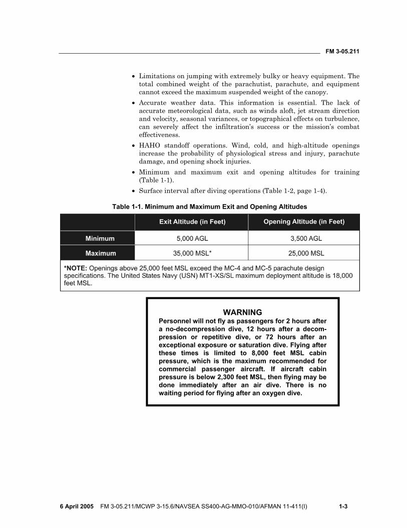
• Minimum and maximum exit and opening altitudes for training (Table 1-1).
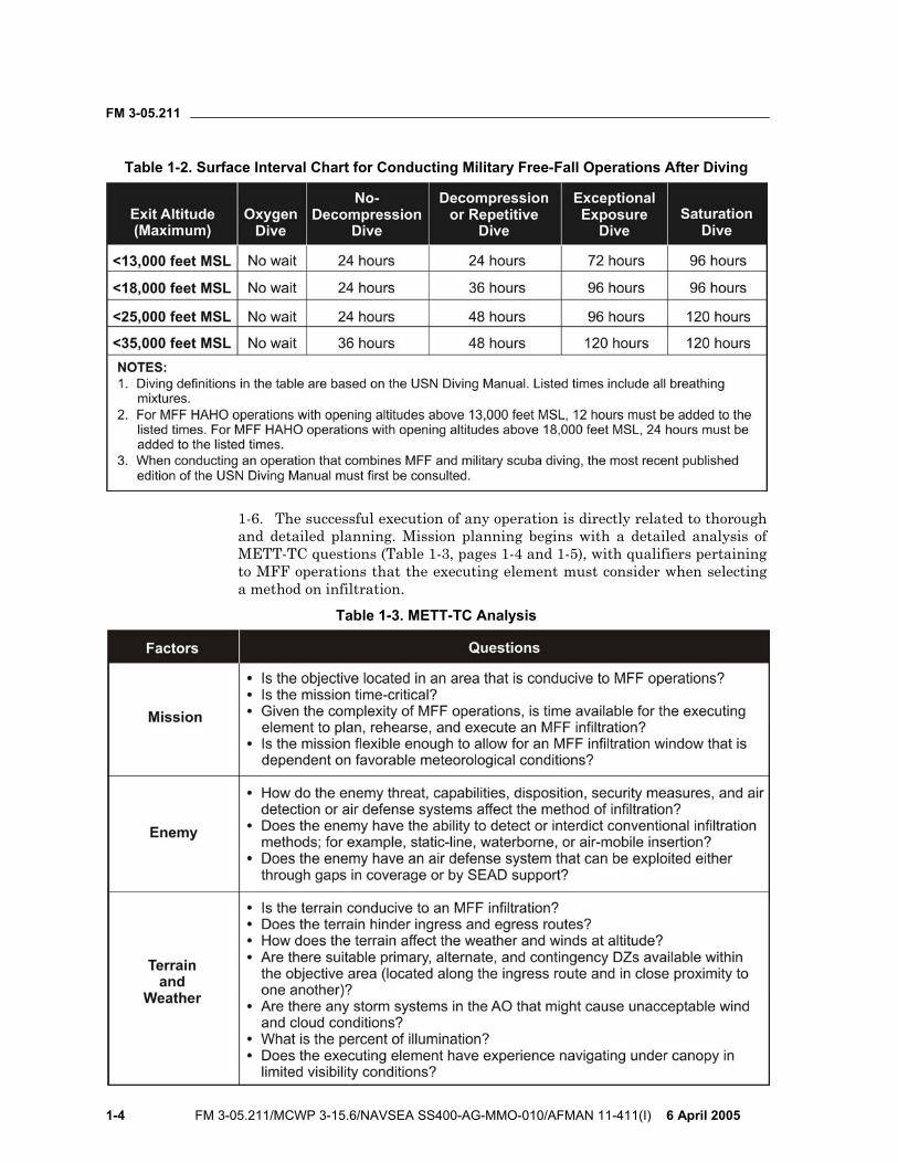
• Surface interval after diving operations (Table 1-2, page 1-4).
Table 1-1. Minimum and Maximum Exit and Opening Altitudes
WARNING Personnel will not fly as passengers for 2 hours after a no-decompression dive, 12 hours after a decom-pression or repetitive dive, or 72 hours after an exceptional exposure or saturation dive. Flying after these times is limited to 8,000 feet MSL cabin pressure, which is the maximum recommended for commercial passenger aircraft. If aircraft cabin pressure is below 2,300 feet MSL, then flying may be done immediately after an air dive. There is no waiting period for flying after an oxygen dive.
FM 3-05.211
1-4 FM 3-05.211/MCWP 3-15.6/NAVSEA SS400-AG-MMO-010/AFMAN 11-411(I) 6 April 2005
Table 1-2. Surface Interval Chart for Conducting Military Free-Fall Operations After Diving
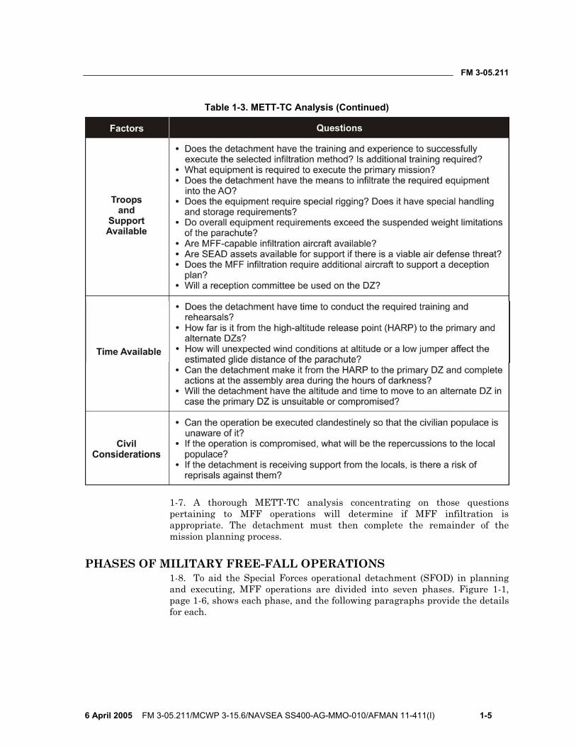
1-6. The successful execution of any operation is directly related to thorough and detailed planning. Mission planning begins with a detailed analysis of METT-TC questions (Table 1-3, pages 1-4 and 1-5), with qualifiers pertaining to MFF operations that the executing element must consider when selecting a method on infiltration.
Table 1-3. METT-TC Analysis
FM 3-05.211
6 April 2005 FM 3-05.211/MCWP 3-15.6/NAVSEA SS400-AG-MMO-010/AFMAN 11-411(I) 1-5
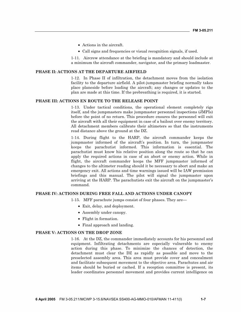
Table 1-3. METT-TC Analysis (Continued)
1-7. A thorough METT-TC analysis concentrating on those questions pertaining to MFF operations will determine if MFF infiltration is appropriate. The detachment must then complete the remainder of the mission planning process.
PHASES OF MILITARY FREE-FALL OPERATIONS 1-8. To aid the Special Forces operational detachment (SFOD) in planning and executing, MFF operations are divided into seven phases. Figure 1-1, page 1-6, shows each phase, and the following paragraphs provide the details for each.

FM 3-05.211
1-6 FM 3-05.211/MCWP 3-15.6/NAVSEA SS400-AG-MMO-010/AFMAN 11-411(I) 6 April 2005
Figure 1-1. Military Free-Fall Operations Planning Phases
PHASE I: PREINFILTRATION PREPARATION 1-9. Preinfiltration preparation starts with preparing an estimate of the situation. The detachment uses the military decision-making process (MDMP) to identify critical nodes in the mission and develop courses of action (COAs) to address them. During this phase, the detachment will plan the mission, prepare plans and orders, conduct briefbacks, conduct training, prepare equipment, and conduct inspections and rehearsals.
1-10. The air mission brief is one of the key briefings conducted during premission planning. The air mission brief takes place during isolation, before the briefback. The ground commander, primary jumpmaster, and aircrew conduct face-to-face coordination to discuss the following items:
• Flight routes and in-flight checkpoints, to include the point of no return.
• En route mission-abort criteria. • En route EPA procedures. • Emergency landing procedures.
FM 3-05.211
6 April 2005 FM 3-05.211/MCWP 3-15.6/NAVSEA SS400-AG-MMO-010/AFMAN 11-411(I) 1-7
• Actions in the aircraft. • Call signs and frequencies or visual recognition signals, if used.
1-11. Aircrew attendance at the briefing is mandatory and should include at a minimum the aircraft commander, navigator, and the primary loadmaster.
PHASE II: ACTIONS AT THE DEPARTURE AIRFIELD 1-12. In Phase II of infiltration, the detachment moves from the isolation facility to the departure airfield. A pilot-jumpmaster briefing normally takes place planeside before loading the aircraft; any changes or updates to the plan are made at this time. If the prebreathing is required, it is started.
PHASE III: ACTIONS EN ROUTE TO THE RELEASE POINT 1-13. Under tactical conditions, the operational element completely rigs itself, and the jumpmasters make jumpmaster personnel inspections (JMPIs) before the point of no return. This procedure ensures the personnel will exit the aircraft with all their equipment in case of a bailout over enemy territory. All detachment members calibrate their altimeters so that the instruments read distance above the ground at the DZ. 1-14. During flight to the HARP, the aircraft commander keeps the jumpmaster informed of the aircraft’s position. In turn, the jumpmaster keeps the parachutist informed. This information is essential. The parachutist must know his relative position along the route so that he can apply the required actions in case of an abort or enemy action. While in flight, the aircraft commander keeps the MFF jumpmaster informed of changes to the altimeter reading should it be necessary to abort and make an emergency exit. All actions and time warnings issued will be IAW premission briefings and this manual. The pilot will signal the jumpmaster upon arriving at the HARP. The parachutists exit the aircraft on the jumpmaster’s command.
PHASE IV: ACTIONS DURING FREE FALL AND ACTIONS UNDER CANOPY 1-15. MFF parachute jumps consist of four phases. They are—
• Exit, delay, and deployment. • Assembly under canopy. • Flight in formation. • Final approach and landing.
PHASE V: ACTIONS ON THE DROP ZONE 1-16. At the DZ, the commander immediately accounts for his personnel and equipment. Infiltrating detachments are especially vulnerable to enemy action during this phase. To minimize the chances of detection, the detachment must clear the DZ as rapidly as possible and move to the preselected assembly area. This area must provide cover and concealment and facilitate subsequent movement to the objective area. Parachutes and air items should be buried or cached. If a reception committee is present, its leader coordinates personnel movement and provides current intelligence on
FM 3-05.211
1-8 FM 3-05.211/MCWP 3-15.6/NAVSEA SS400-AG-MMO-010/AFMAN 11-411(I) 6 April 2005
the enemy situation. Finally, the detachment sterilizes the assembly area and begins moving to the objective area.
PHASE VI: MOVEMENT TO AND ACTIONS AT THE OBJECTIVE 1-17. Movement from the DZ to the objective area may require guides. If a reception committee is present, it provides guides to the area or mission support sites where additional equipment brought ashore may be cached. If guides are not available, the detachment follows the preselected route based on detailed intelligence and the patrolling plan developed during isolation. The route must take maximum advantage of cover and concealment and avoid enemy outposts, patrols, and installations. The detachment carries only mission-essential equipment and supplies (individual equipment, weapons, communications, and ammunition).
PHASE VII: EXFILTRATION 1-18. Exfiltration planning considerations require the same planning, preparations, tactics, and techniques as infiltrations do. However, in exfiltration the planners are primarily concerned with recovery methods. Distances involved in exfiltration usually require additional means of transport. Fixed- or rotary-wing aircraft, vehicles, surface craft, submarines, or various combinations of these methods can be used to recover operational elements.
FM 3-05.211
6 April 2005 FM 3-05.211/MCWP 3-15.6/NAVSEA SS400-AG-MMO-010/AFMAN 11-411(I) 2-1
Chapter 2
MC-4 Ram-Air Parachute System The evolution of the parachute used in MFF operations has been considerable over the years. This chapter identifies the MC-4 RAPS components and donning and recovery procedures. There are several RAPSs used in DOD that have similar employment and flight characteristics to the MC-4—the USN MT1-XS/SL and MT2-XX/SL, and the United States Marine Corps (USMC) MC-5. All three RAPSs have a static-line capability, though the MT1-XS/SL has a smaller reserve canopy. NOTE: Questions regarding employment of the RAPS in the static-line configuration should be addressed to the Airborne School, Fort Benning, Georgia. Technical manual (TM) 10-1670-287-23&P, Unit and Direct Support Maintenance Manual for MC-4 Ram-Air Free-Fall Personnel Parachute System, contains information on repairing and maintaining the MC-4; USMC TM 09770A-12&P/1A, Operational Instructions and Organizational Maintenance With Illustrated Parts Breakdown for the Ram-Air Parachute Assembly, MC-5, contains information for the MC-5; and Naval Air Systems Command (NAVAIR) 13-1-21, Organizational Maintenance With Illustrated Parts Breakdown for the Ram-Air Parachute Assembly (MT1-XS/SL), contains information for the MT1-XS/SL.
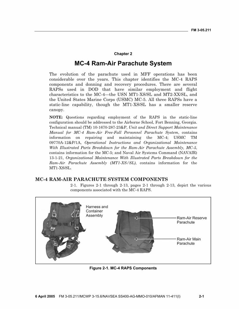
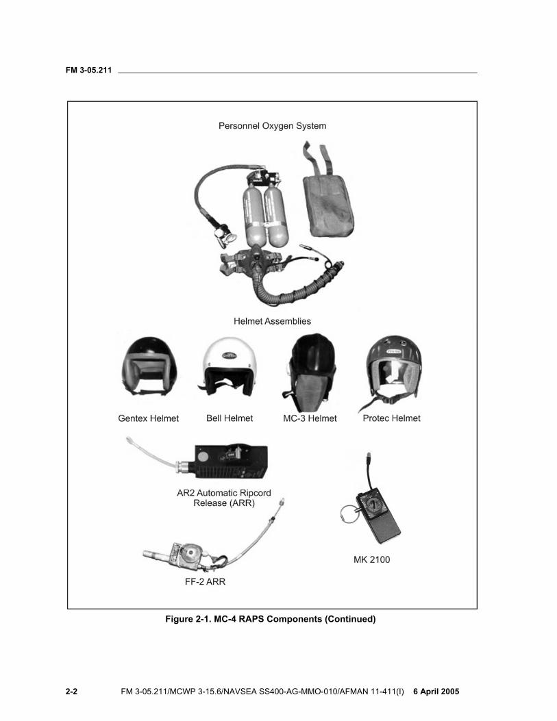
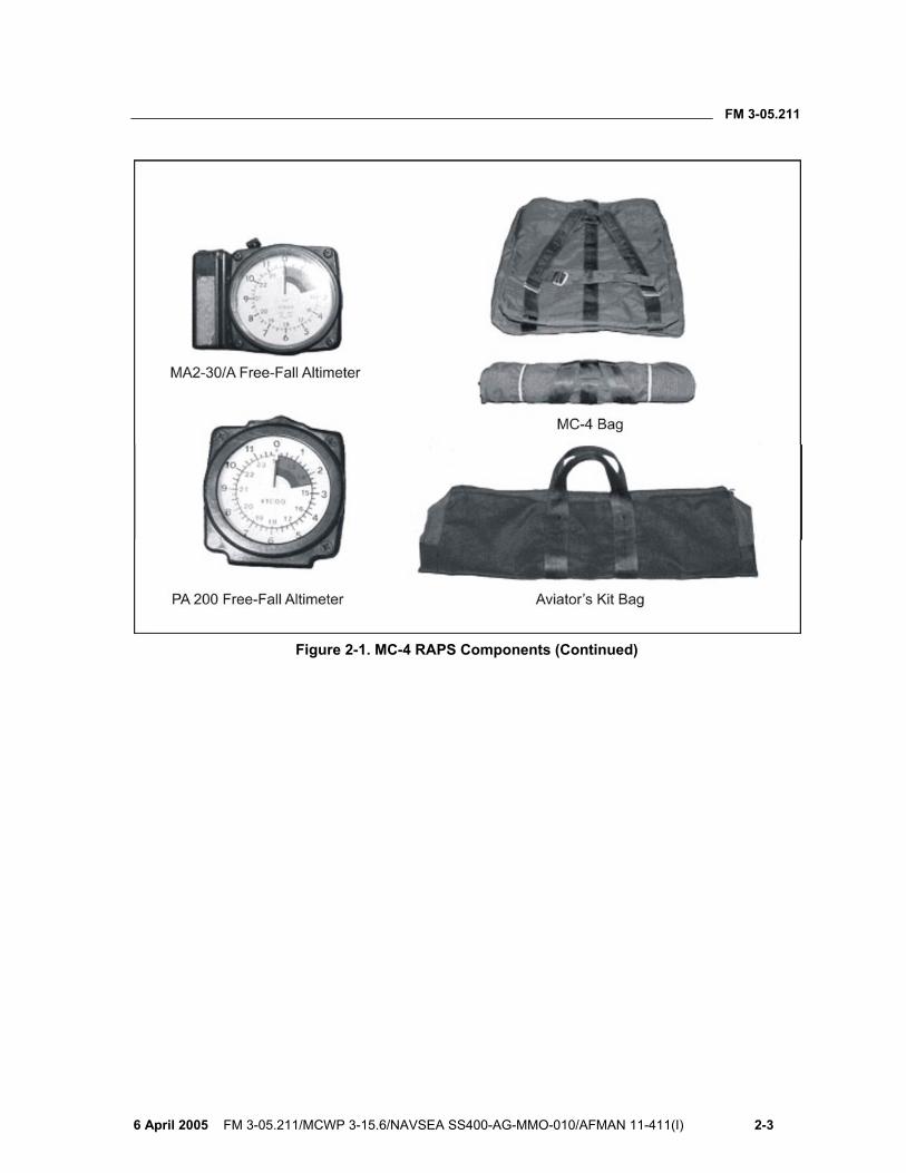
MC-4 RAM-AIR PARACHUTE SYSTEM COMPONENTS 2-1. Figures 2-1 through 2-13, pages 2-1 through 2-13, depict the various components associated with the MC-4 RAPS.
Figure 2-1. MC-4 RAPS Components
FM 3-05.211
2-2 FM 3-05.211/MCWP 3-15.6/NAVSEA SS400-AG-MMO-010/AFMAN 11-411(I) 6 April 2005
Figure 2-1. MC-4 RAPS Components (Continued)
FM 3-05.211
6 April 2005 FM 3-05.211/MCWP 3-15.6/NAVSEA SS400-AG-MMO-010/AFMAN 11-411(I) 2-3
Figure 2-1. MC-4 RAPS Components (Continued)
FM 3-05.211
2-4 FM 3-05.211/MCWP 3-15.6/NAVSEA SS400-AG-MMO-010/AFMAN 11-411(I) 6 April 2005
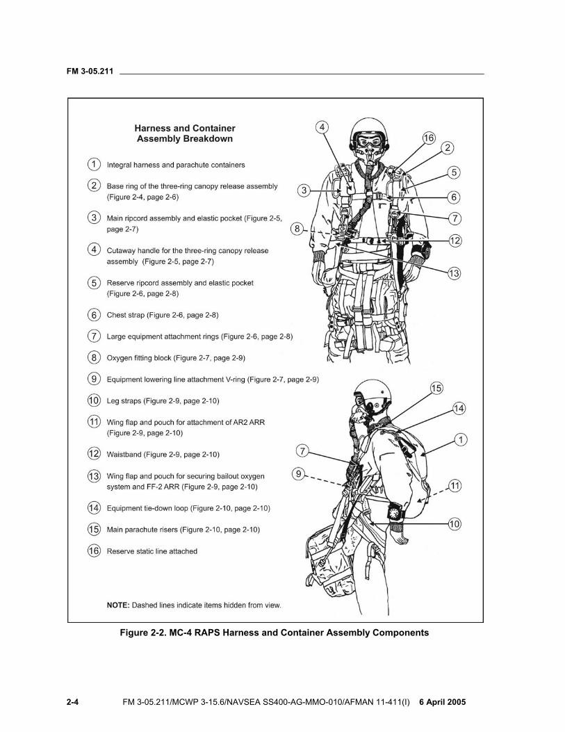
Figure 2-2. MC-4 RAPS Harness and Container Assembly Components
FM 3-05.211
6 April 2005 FM 3-05.211/MCWP 3-15.6/NAVSEA SS400-AG-MMO-010/AFMAN 11-411(I) 2-5
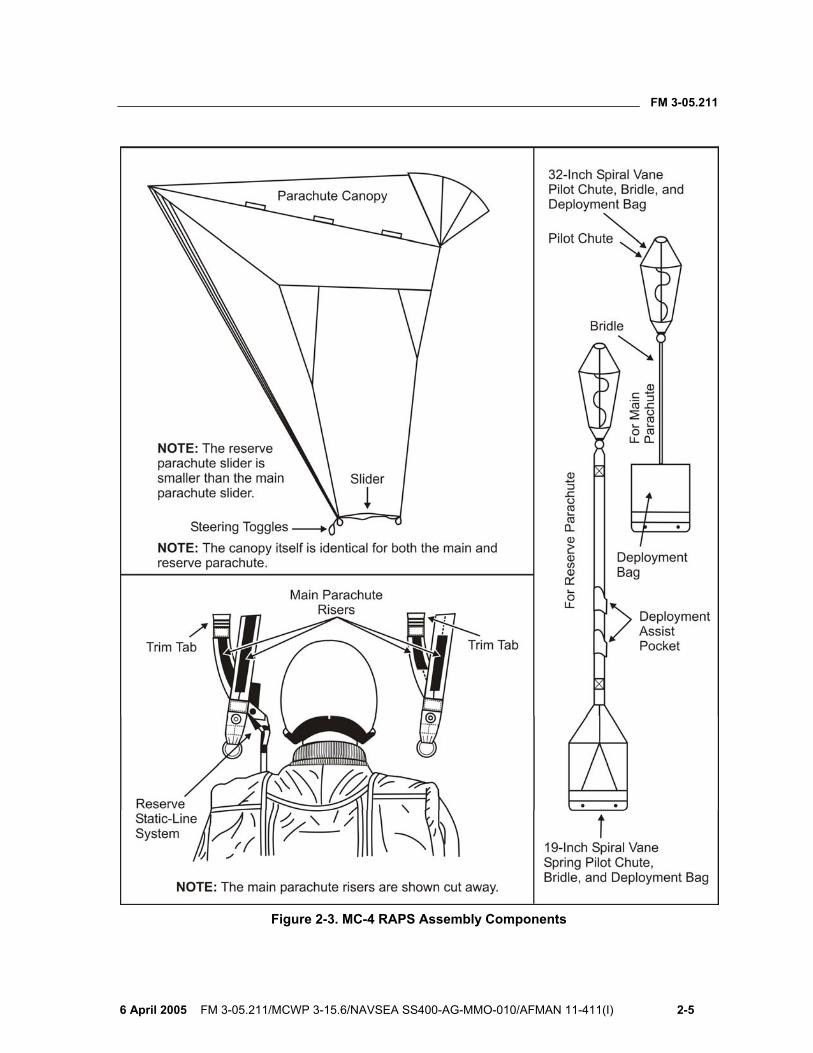
Figure 2-3. MC-4 RAPS Assembly Components

FM 3-05.211
2-6 FM 3-05.211/MCWP 3-15.6/NAVSEA SS400-AG-MMO-010/AFMAN 11-411(I) 6 April 2005
Figure 2-4. Location of the Three-Ring Canopy Release Assembly
FM 3-05.211
6 April 2005 FM 3-05.211/MCWP 3-15.6/NAVSEA SS400-AG-MMO-010/AFMAN 11-411(I) 2-7
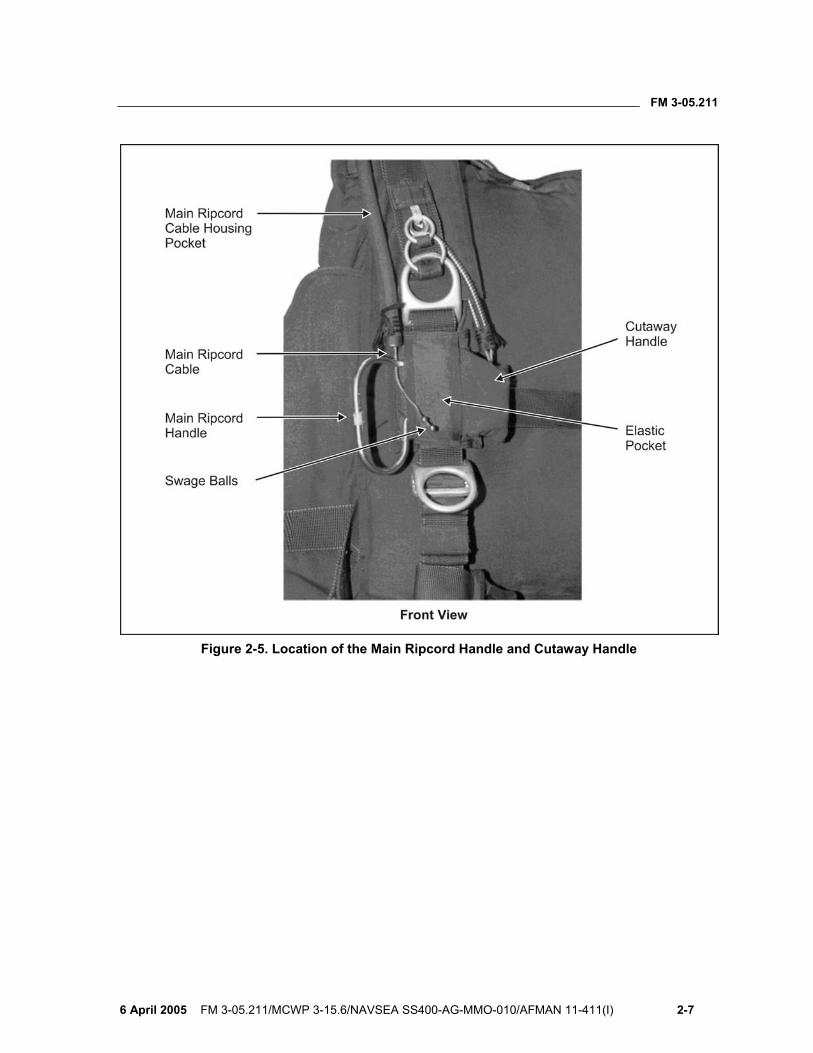
Figure 2-5. Location of the Main Ripcord Handle and Cutaway Handle
FM 3-05.211
2-8 FM 3-05.211/MCWP 3-15.6/NAVSEA SS400-AG-MMO-010/AFMAN 11-411(I) 6 April 2005
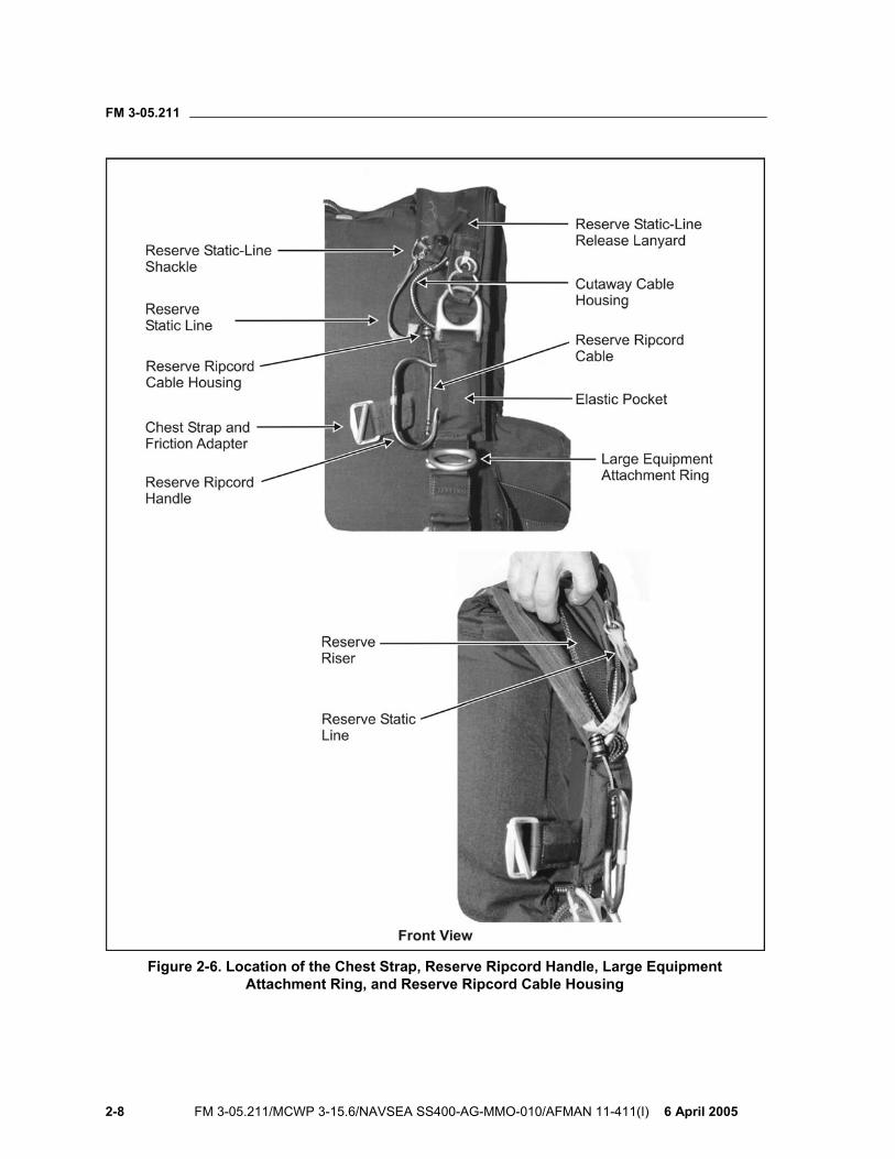
Figure 2-6. Location of the Chest Strap, Reserve Ripcord Handle, Large Equipment Attachment Ring, and Reserve Ripcord Cable Housing
FM 3-05.211
6 April 2005 FM 3-05.211/MCWP 3-15.6/NAVSEA SS400-AG-MMO-010/AFMAN 11-411(I) 2-9
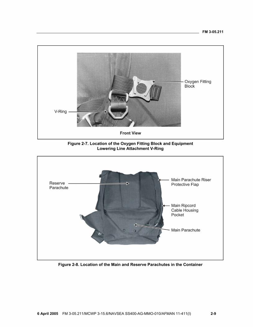
Figure 2-7. Location of the Oxygen Fitting Block and Equipment Lowering Line Attachment V-Ring
Figure 2-8. Location of the Main and Reserve Parachutes in the Container

FM 3-05.211
2-10 FM 3-05.211/MCWP 3-15.6/NAVSEA SS400-AG-MMO-010/AFMAN 11-411(I) 6 April 2005
Figure 2-9. Location of Straps
Figure 2-10. Location of the Equipment Tie-Down Loop and Main Risers

FM 3-05.211
6 April 2005 FM 3-05.211/MCWP 3-15.6/NAVSEA SS400-AG-MMO-010/AFMAN 11-411(I) 2-11
Figure 2-11. Location of Main and Reserve Components
FM 3-05.211
2-12 FM 3-05.211/MCWP 3-15.6/NAVSEA SS400-AG-MMO-010/AFMAN 11-411(I) 6 April 2005
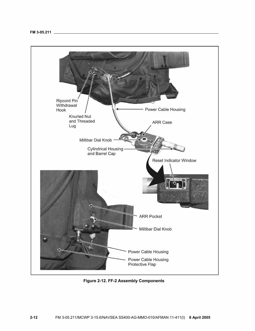
Figure 2-12. FF-2 Assembly Components
FM 3-05.211
6 April 2005 FM 3-05.211/MCWP 3-15.6/NAVSEA SS400-AG-MMO-010/AFMAN 11-411(I) 2-13
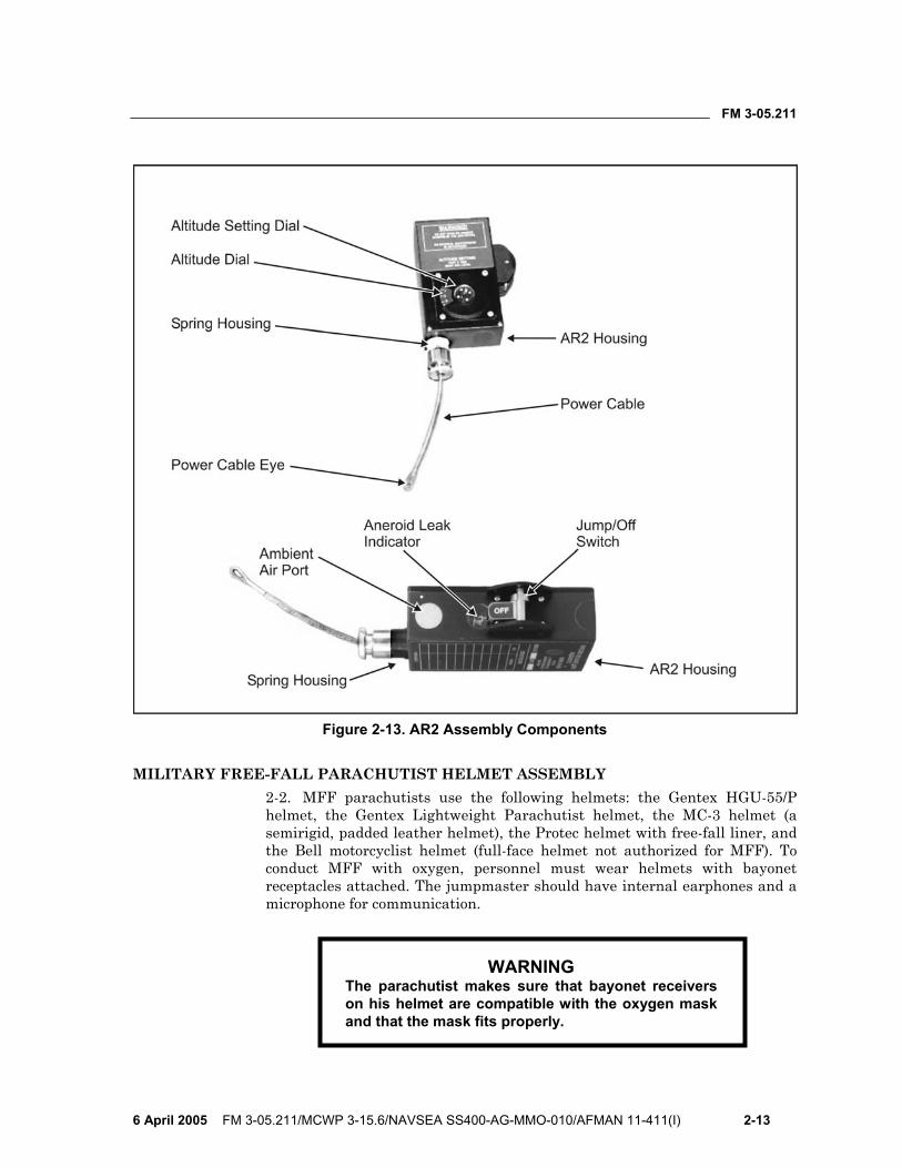
Figure 2-13. AR2 Assembly Components
MILITARY FREE-FALL PARACHUTIST HELMET ASSEMBLY 2-2. MFF parachutists use the following helmets: the Gentex HGU-55/P helmet, the Gentex Lightweight Parachutist helmet, the MC-3 helmet (a semirigid, padded leather helmet), the Protec helmet with free-fall liner, and the Bell motorcyclist helmet (full-face helmet not authorized for MFF). To conduct MFF with oxygen, personnel must wear helmets with bayonet receptacles attached. The jumpmaster should have internal earphones and a microphone for communication.
WARNING The parachutist makes sure that bayonet receivers on his helmet are compatible with the oxygen mask and that the mask fits properly.
FM 3-05.211
2-14 FM 3-05.211/MCWP 3-15.6/NAVSEA SS400-AG-MMO-010/AFMAN 11-411(I) 6 April 2005
WARNING The clear full-face shield (issued with the Gentex helmet and jumped with the oxygen mask) may become dislodged in free fall if not properly fitted and tightened.
2-3. MFF parachutists must use eye protection. Commercial (Kroop) goggles provide a wide field of vision and come in two sizes: regular and a larger box design that fits over standard military eyeglasses. Military-issue sun, wind, and dust goggles are authorized but not recommended because they restrict the parachutist’s field of vision. Both of these goggles are authorized for parachuting with or without an oxygen mask. The clear full-face shield issued with the Gentex helmet is authorized for use only with an oxygen mask. All lenses used should be clear and relatively free of scratches that might obstruct vision.
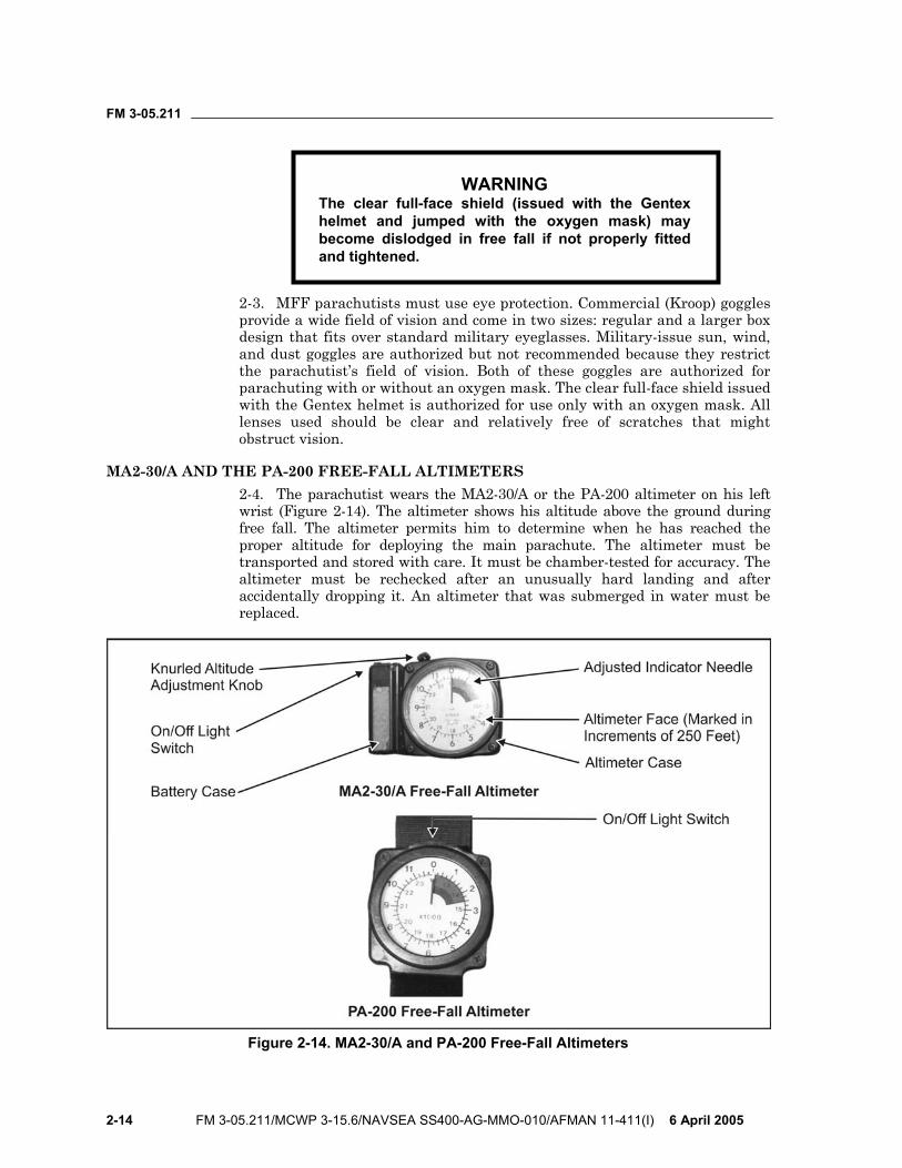
MA2-30/A AND THE PA-200 FREE-FALL ALTIMETERS 2-4. The parachutist wears the MA2-30/A or the PA-200 altimeter on his left wrist (Figure 2-14). The altimeter shows his altitude above the ground during free fall. The altimeter permits him to determine when he has reached the proper altitude for deploying the main parachute. The altimeter must be transported and stored with care. It must be chamber-tested for accuracy. The altimeter must be rechecked after an unusually hard landing and after accidentally dropping it. An altimeter that was submerged in water must be replaced.
Figure 2-14. MA2-30/A and PA-200 Free-Fall Altimeters
FM 3-05.211
6 April 2005 FM 3-05.211/MCWP 3-15.6/NAVSEA SS400-AG-MMO-010/AFMAN 11-411(I) 2-15
2-5. The computation for the altimeter setting follows. The parachutist— • Finds the difference in elevation between the departure airfield (DAF)
and the DZ. • If the DAF is lower than the DZ, sets the altimeter back (–), or to the
left. • If the DAF is higher than the DZ, sets the altimeter forward (+), or to
the right. • If the DAF and DZ elevation are the same, makes no adjustment to the
altimeter except to place the altitude indicator arrow on zero.
CAUTION Special consideration will be given to any obstacles (for example, ridgelines, mountains, towers, and other such items and their elevations) that may be located within 3 nautical miles or 5.5 kilometers of the parachutist’s release point (RP) or desired impact point (DIP). These obstacles may force the parachutist to consider alternatives to HALO.
OTHER RECOMMENDED ITEMS 2-6. Boots (without speed lacing hooks) are not RAPS components; however, they are considered mandatory safety equipment. Different types of gloves, boots, and jumpsuits may be necessary depending upon the degree of environmental protection required.
DONNING AND RECOVERING THE MC-4 RAM-AIR PARACHUTE SYSTEM
2-7. The buddy system, or the pairing of parachutists, within each operational element provides the most efficient and accurate way for parachutists to don, adjust, and check each other’s parachutes. Using the buddy system to properly don and adjust the MC-4 RAPS provides an additional safety check and prevents unnecessary delays during the JMPI.
PREPARING THE KIT BAGS 2-8. The parachutist determines how he will wear the kit bags. He prepares them as follows:
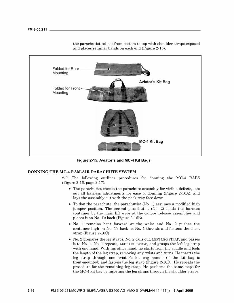
• Aviator’s kit bag. The parachutist closes the slide fastener and secures all snap fasteners. If the kit bag is worn front-mounted, he folds it in two folds from the bottom leaving the handles centered (Figure 2-15, page 2-16). If the kit bag is worn rear-mounted, he folds each end of it with one fold toward the center leaving the handles exposed at one end (Figure 2-15).
• MC-4 kit bag. The parachutist closes the slide fastener. The kit bag can be worn like a rucksack under the MC-4 RAPS. If it is front-mounted,
FM 3-05.211
2-16 FM 3-05.211/MCWP 3-15.6/NAVSEA SS400-AG-MMO-010/AFMAN 11-411(I) 6 April 2005
the parachutist rolls it from bottom to top with shoulder straps exposed and places retainer bands on each end (Figure 2-15).
Figure 2-15. Aviator’s and MC-4 Kit Bags
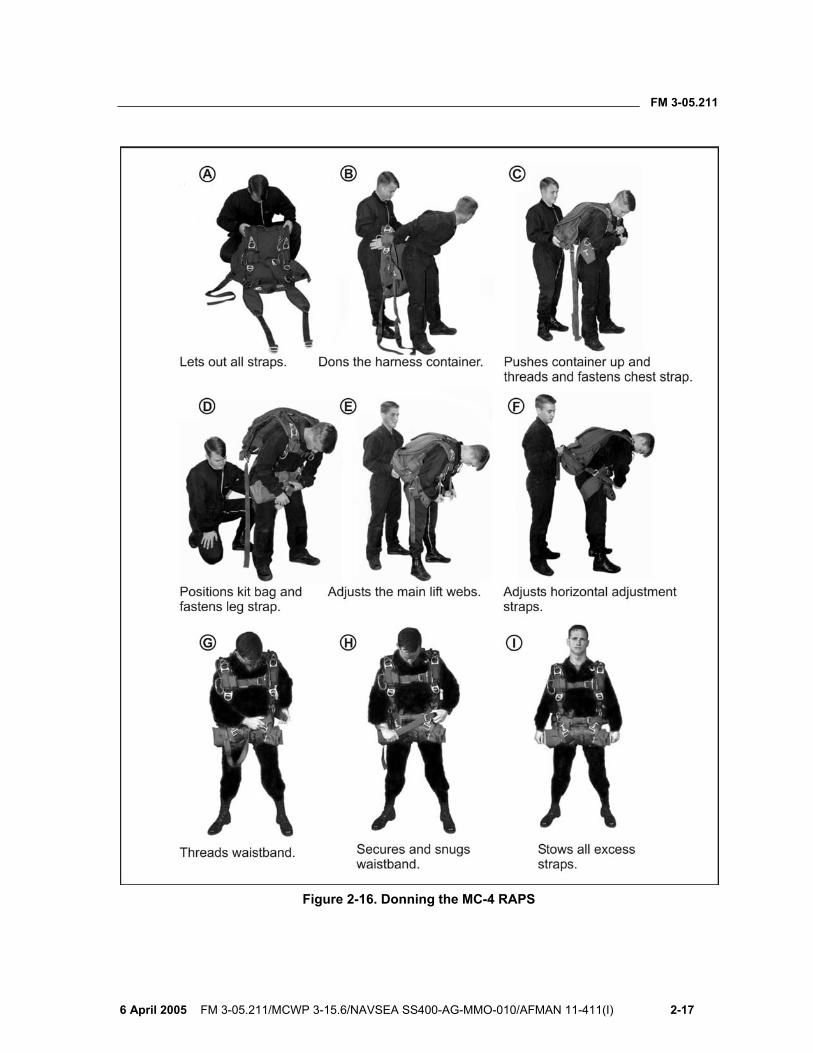
DONNING THE MC-4 RAM-AIR PARACHUTE SYSTEM 2-9. The following outlines procedures for donning the MC-4 RAPS (Figure 2-16, page 2-17):
• The parachutist checks the parachute assembly for visible defects, lets out all harness adjustments for ease of donning (Figure 2-16A), and lays the assembly out with the pack tray face down.
• To don the parachute, the parachutist (No. 1) assumes a modified high jumper position. The second parachutist (No. 2) holds the harness container by the main lift webs at the canopy release assemblies and places it on No. 1’s back (Figure 2-16B).
• No. 1 remains bent forward at the waist and No. 2 pushes the container high on No. 1’s back as No. 1 threads and fastens the chest strap (Figure 2-16C).
• No. 2 prepares the leg straps. No. 2 calls out, LEFT LEG STRAP, and passes it to No. 1. No. 1 repeats, LEFT LEG STRAP, and grasps the left leg strap with one hand. With his other hand, he starts from the saddle and feels the length of the leg strap, removing any twists and turns. He inserts the leg strap through one aviator’s kit bag handle (if the kit bag is front-mounted) and fastens the leg strap (Figure 2-16D). He repeats the procedure for the remaining leg strap. He performs the same steps for the MC-4 kit bag by inserting the leg straps through the shoulder straps.
FM 3-05.211
6 April 2005 FM 3-05.211/MCWP 3-15.6/NAVSEA SS400-AG-MMO-010/AFMAN 11-411(I) 2-17
Figure 2-16. Donning the MC-4 RAPS
FM 3-05.211
2-18 FM 3-05.211/MCWP 3-15.6/NAVSEA SS400-AG-MMO-010/AFMAN 11-411(I) 6 April 2005
• No. 1 stands erect and checks to make sure the canopy release assemblies are in the hollows of his shoulders by adjusting the main lift webs (Figure 2-16E, page 2-17).
• No. 1 locates the free-running ends of the horizontal adjustment straps and tightens the harness so it fits snugly and comfortably (Figure 2-16F).
• No. 2 then threads the long-running end of the waistband through both kit bag handles (if the kit bag is rear-mounted), and No. 1 fastens the waistband to the waistband extension (Figures 2-16G and H).
• After final adjustment, No. 1 folds all excess straps inward, except for the main lift webs that are folded outward, and secures them using the elastic keepers (Figure 2-16I). No. 1 should be able to stand erect without straining.
• When properly donned, the system should feel snug but not so tight as to restrict movement. The jumper should be able to properly arch, look, reach, and pull the ripcord on the ground before the actual jump.
• No. 1 and No. 2 then change positions and repeat the procedure. • When both parachutists have donned their parachute assemblies and
adjusted their harnesses, they face each other, make a visual inspection of each other, and correct any deficiencies before the JMPI.
RECOVERING THE RAM-AIR PARACHUTE SYSTEM 2-10. The parachutist uses the following procedures to recover a RAPS:
• If jumping oxygen, locks the ON/OFF switch in the OFF position and removes the bailout bottles and pouch from the waistband.
NOTE: Parachutists do not place the oxygen mask on the ground unprotected during parachute recovery. Moisture from breathing and condensation due to temperature changes will cause dirt and debris to adhere to the mask, interfering with sealing and increasing risk of injury. • Removes the harness and container and daisy-chains the suspension lines. • Removes and opens the aviator’s kit bag. • Replaces the arming pin in the FF-2 or moves the JUMP/OFF switch to
OFF on the AR2. • Replaces the ripcord in the ripcord cable housing and the ripcord
handle in the stow pocket. • Places the pilot chute next to the kit bag. • Places the canopy, deployment bag, suspension lines, and risers in the
kit bag. • Removes the quick-release snap hooks and lowering line quick-ejector
snap from the equipment rings on the parachute harness. • Places the harness and container in the kit bag with the back pad
facing up to protect the AR2. • Finally, places the pilot chute in the kit bag and snaps or zips the
fasteners.
FM 3-05.211
6 April 2005 FM 3-05.211/MCWP 3-15.6/NAVSEA SS400-AG-MMO-010/AFMAN 11-411(I) 3-1
Chapter 3
Automatic Ripcord Release The ARR is a safety device designed to activate the main or reserve parachute of the RAPS should the parachutist fail to do so. The ARR functions at a predetermined altitude AGL by sensing changes in barometric pressure. The jumpmaster calculates the proper millibar setting and inspects the ARR for the proper setting. The current ARRs include the FF-2 Hite Finder, the AR2, the Sentinel MK 2100, and the Military Cybernetic Parachute Release System (CYPRES). TM 10-1670-305-23&P, Unit and Direct Support Maintenance Manual for Automatic Ripcord Release, AR2, and TM 10-1670-300-20&P, Unit and Direct Support Maintenance Manual for Ancillary Equipment for Military Free-Fall System, provide further information.
AUTOMATIC RIPCORD RELEASE ACTIVATION SETTING AND OPERATION
3-1. The ARRs are set to activate at 500 feet or more below the briefed main parachute manual activation altitude; however, they are not under any circumstances set to activate below the ARR’s prescribed activation altitude. The activation altitudes are 2,500 feet AGL for the FF-2, 1,500 feet AGL for the AR2, and 1,500 feet AGL for the MK 2100. The ARRs sense the altitude 1,000 feet above the MSL activation altitude. The ARR fires after the timer’s activation, withdrawing the ripcord pin from the main or the reserve parachute-closing loop, depending on the ARR model. The process cannot be stopped once the timer is activated.
NOTE: The ARR is a mechanical safety device. It is a secondary means to activate the main or reserve parachute. Its use is mandatory for all MFF operations.
FF-2 AUTOMATIC RIPCORD RELEASE 3-2. The FF-2 ARR (Figure 3-1, page 3-2) is a main parachute-mounted ARR. The FF-2 automatically opens an MFF parachutist’s parachute at the preset altitude when the parachutist fails to pull the manual ripcord at the prescribed pull altitude. The FF-2’s mechanical response depends on presetting the instrument for the barometric pressure at the desired activation altitude, computed in millibars, above the intended DZ.
FM 3-05.211
3-2 FM 3-05.211/MCWP 3-15.6/NAVSEA SS400-AG-MMO-010/AFMAN 11-411(I) 6 April 2005
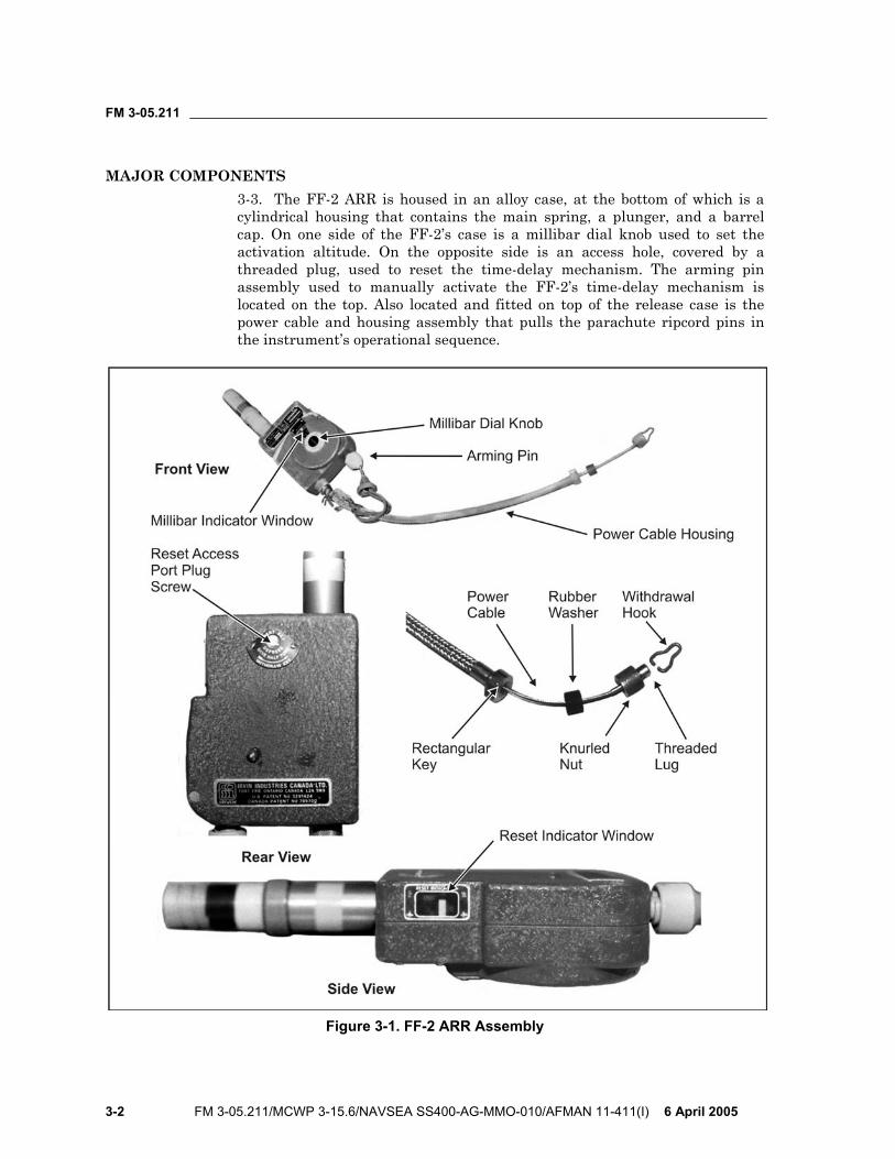
MAJOR COMPONENTS 3-3. The FF-2 ARR is housed in an alloy case, at the bottom of which is a cylindrical housing that contains the main spring, a plunger, and a barrel cap. On one side of the FF-2’s case is a millibar dial knob used to set the activation altitude. On the opposite side is an access hole, covered by a threaded plug, used to reset the time-delay mechanism. The arming pin assembly used to manually activate the FF-2’s time-delay mechanism is located on the top. Also located and fitted on top of the release case is the power cable and housing assembly that pulls the parachute ripcord pins in the instrument’s operational sequence.
Figure 3-1. FF-2 ARR Assembly
FM 3-05.211
6 April 2005 FM 3-05.211/MCWP 3-15.6/NAVSEA SS400-AG-MMO-010/AFMAN 11-411(I) 3-3
PRINCIPLE OF OPERATION 3-4. The FF-2 senses the barometric pressure in inches of mercury (Hg) and is set to activate a minimum of 500 feet below the manual pull altitude of the parachute. The FF-2 minimum activation setting is 2,500 feet AGL.
CHECKING THE RESET INDICATOR 3-5. The parachutist can check the reset operation using the “RESET INDICATOR” window (Figure 3-1, page 3-2), located immediately below the FF-2 case’s rounded face, by visually checking the window and observing the location of the two white marks. If the FF-2’s time-delay mechanism has been reset, the two marks will be aligned. If the lower, movable mark is offset more than one half the width of the indicator, the time-delay mechanism may not have been reset properly. The parachutist should replace an FF-2 that has not been reset with another FF-2 that has been reset, or have the support rigger reset the time-delay mechanism.
INSTALLATION AND REMOVAL 3-6. In most cases, the FF-2 ARR has been installed when the parachute is issued. The FF-2 ARR fits into a stowage pocket specifically designed to contain it. Should the parachutist have to install the release, he follows the procedures in Figure 3-2, page 3-4.
WARNING Due to the exposed mounting location of the FF-2 ARR, personnel must take extreme care when handling, storing, and transporting an MC-4 steerable parachute.
3-7. Personnel should follow the steps outlined below to remove the FF-2 ARR from the parachute:
• Remove the withdrawal hook by unscrewing the knurled locking nut and removing it from the retainer slot.
• Rotate the withdrawal hook off the locking pin. • Reinstall the open end of the withdrawal hook in the hook retainer slot
and secure it to the retainer by screwing the knurled locking nut back across the retainer.
• Remove the FF-2 from the parachute’s ARR pocket.
FF-2 MILLIBAR SETTING CALCULATION 3-8. The jumpmaster obtains the forecasted aircraft “altimeter setting” for the DZ. The altimeter (pressure) setting will be given in inches of mercury. The jumpmaster obtains the setting to the nearest one-hundredth of an inch. If flying a mission with limited weather information, the aircrew can provide the altimeter setting en route to the drop area.

FM 3-05.211
3-4 FM 3-05.211/MCWP 3-15.6/NAVSEA SS400-AG-MMO-010/AFMAN 11-411(I) 6 April 2005
Figure 3-2. Installing the FF-2 ARR
FM 3-05.211
6 April 2005 FM 3-05.211/MCWP 3-15.6/NAVSEA SS400-AG-MMO-010/AFMAN 11-411(I) 3-5
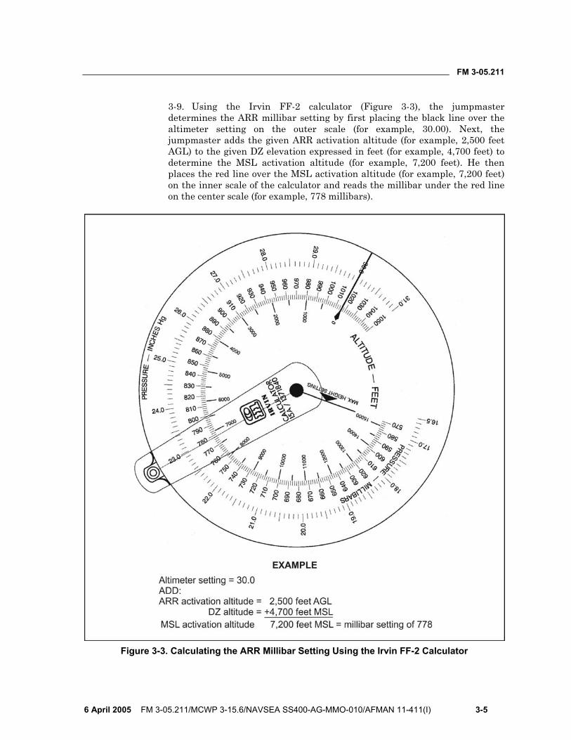
3-9. Using the Irvin FF-2 calculator (Figure 3-3), the jumpmaster determines the ARR millibar setting by first placing the black line over the altimeter setting on the outer scale (for example, 30.00). Next, the jumpmaster adds the given ARR activation altitude (for example, 2,500 feet AGL) to the given DZ elevation expressed in feet (for example, 4,700 feet) to determine the MSL activation altitude (for example, 7,200 feet). He then places the red line over the MSL activation altitude (for example, 7,200 feet) on the inner scale of the calculator and reads the millibar under the red line on the center scale (for example, 778 millibars).
Figure 3-3. Calculating the ARR Millibar Setting Using the Irvin FF-2 Calculator
FM 3-05.211
3-6 FM 3-05.211/MCWP 3-15.6/NAVSEA SS400-AG-MMO-010/AFMAN 11-411(I) 6 April 2005
FF-2 ARMING AND DISARMING 3-10. On the jumpmaster’s command, the parachutist removes the arming pin to arm the FF-2. The safe arming altitude for the FF-2 is 2,500 feet above the MSL activation altitude. If the aircraft must descend below the safe arming altitude, the parachutist reinserts the arming pin to disarm the FF-2. He must disarm the FF-2 not lower than 2,500 feet above the MSL activation altitude to prevent an inadvertent firing. The minimum exit altitude when using the FF-2 is 5,000 feet AGL (2,500-foot minimum activation setting plus 2,500-foot arming requirement).
AR2 AUTOMATIC RIPCORD RELEASE, M451 3-11. The AR2 is an all-mechanical automatic opening device (AOD) that contains a pressure-sensing aneroid capsule. The AR2 is designed to release its spring-powered actuation mechanism and deploy a parachute when the surrounding atmospheric pressure has compressed the aneroid capsule to a length corresponding to a specific preset altitude, provided that the descent velocity at that point exceeds a required minimum limit. The relationship between external pressure and actuation altitude of the AR2 is established during manufacture by means of a uniform calibration procedure. This procedure ensures that all AR2s respond alike, within a prescribed tolerance, to a given external pressure.
3-12. The AR2 automatically deploys a parachute at a predetermined altitude. The AR2 is designed to open the reserve parachute but can be used with the main parachute. It may also be used with cargo parachutes. The AR2 senses rate of fall and altitude above MSL (not AGL). The AR2 actuates when it falls through a preselected altitude at a fall rate of 80 feet per second (ft/sec) or greater. Altitude settings are in 250-foot increments.
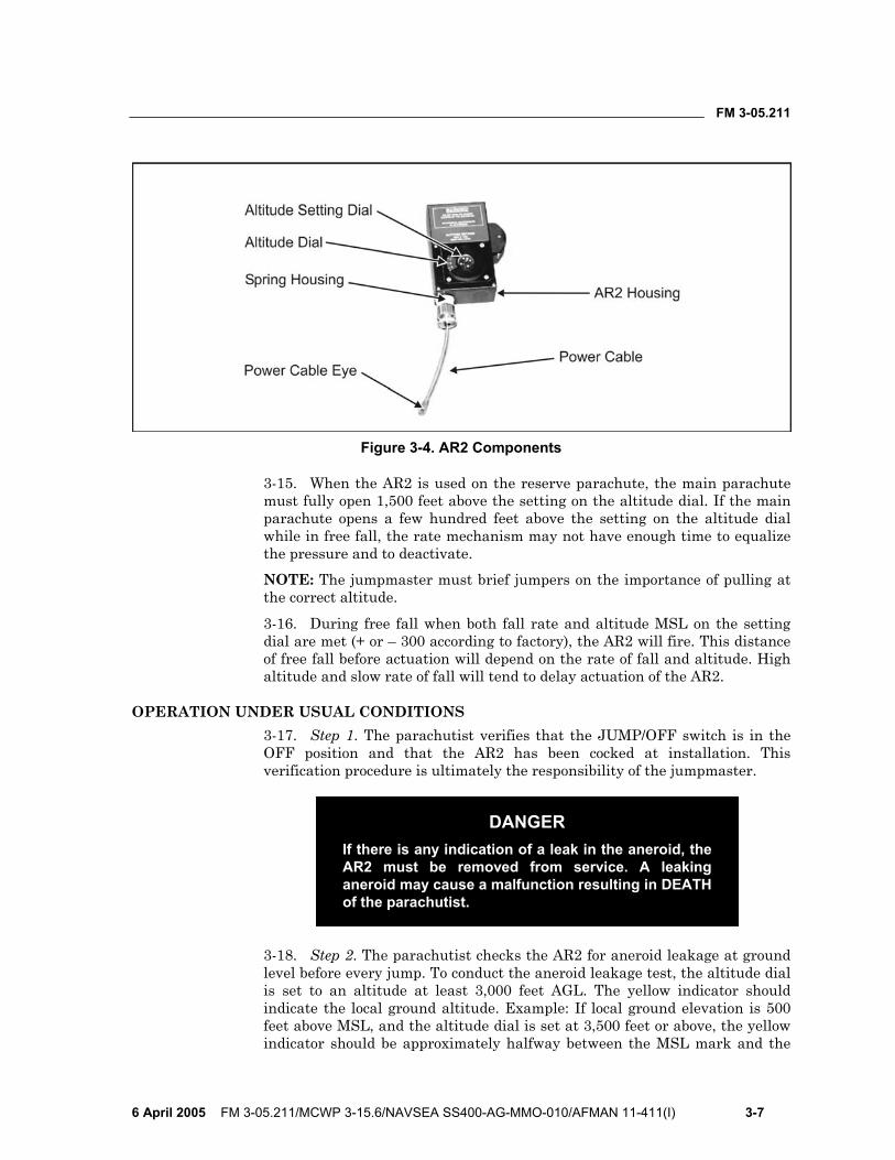
MAJOR COMPONENTS 3-13. The AR2 basically consists of an aneroid with associated mechanism, rate-of-fall sensing chamber, and a spring-loaded power cable. All components, except the power cable and its flexible housing, are contained in a housing. The housing provides all required chambers, passages, and mounting pads for each component. An altitude setting dial and JUMP/OFF switch are mounted on the housing. The power cable supplied for use with the reserve parachute has a fixed eye that connects to the reserve parachute ripcord pin. Figure 3-4, page 3-7, shows the AR2 components.
PRINCIPLES OF OPERATION 3-14. The AR2 senses the rate of fall and altitude above MSL (not AGL). When the AR2 falls through the altitude set on the altitude dial at a rate of fall of over 0.0368 pounds per square inch/second (psi/sec) (which equates to 80 ft/sec at an altitude above MSL of 5,500 feet), the power cable will retract 2 inches (minimum) and at an initial force of 70 pounds. If the rate of fall is at a slower speed, such as 70 ft/sec measured at 5,500 feet, the AR2 will not actuate.
FM 3-05.211
6 April 2005 FM 3-05.211/MCWP 3-15.6/NAVSEA SS400-AG-MMO-010/AFMAN 11-411(I) 3-7
Figure 3-4. AR2 Components
3-15. When the AR2 is used on the reserve parachute, the main parachute must fully open 1,500 feet above the setting on the altitude dial. If the main parachute opens a few hundred feet above the setting on the altitude dial while in free fall, the rate mechanism may not have enough time to equalize the pressure and to deactivate. NOTE: The jumpmaster must brief jumpers on the importance of pulling at the correct altitude.
3-16. During free fall when both fall rate and altitude MSL on the setting dial are met (+ or – 300 according to factory), the AR2 will fire. This distance of free fall before actuation will depend on the rate of fall and altitude. High altitude and slow rate of fall will tend to delay actuation of the AR2.
OPERATION UNDER USUAL CONDITIONS 3-17. Step 1. The parachutist verifies that the JUMP/OFF switch is in the OFF position and that the AR2 has been cocked at installation. This verification procedure is ultimately the responsibility of the jumpmaster.
DANGER If there is any indication of a leak in the aneroid, the AR2 must be removed from service. A leaking aneroid may cause a malfunction resulting in DEATH of the parachutist.
3-18. Step 2. The parachutist checks the AR2 for aneroid leakage at ground level before every jump. To conduct the aneroid leakage test, the altitude dial is set to an altitude at least 3,000 feet AGL. The yellow indicator should indicate the local ground altitude. Example: If local ground elevation is 500 feet above MSL, and the altitude dial is set at 3,500 feet or above, the yellow indicator should be approximately halfway between the MSL mark and the
FM 3-05.211
3-8 FM 3-05.211/MCWP 3-15.6/NAVSEA SS400-AG-MMO-010/AFMAN 11-411(I) 6 April 2005
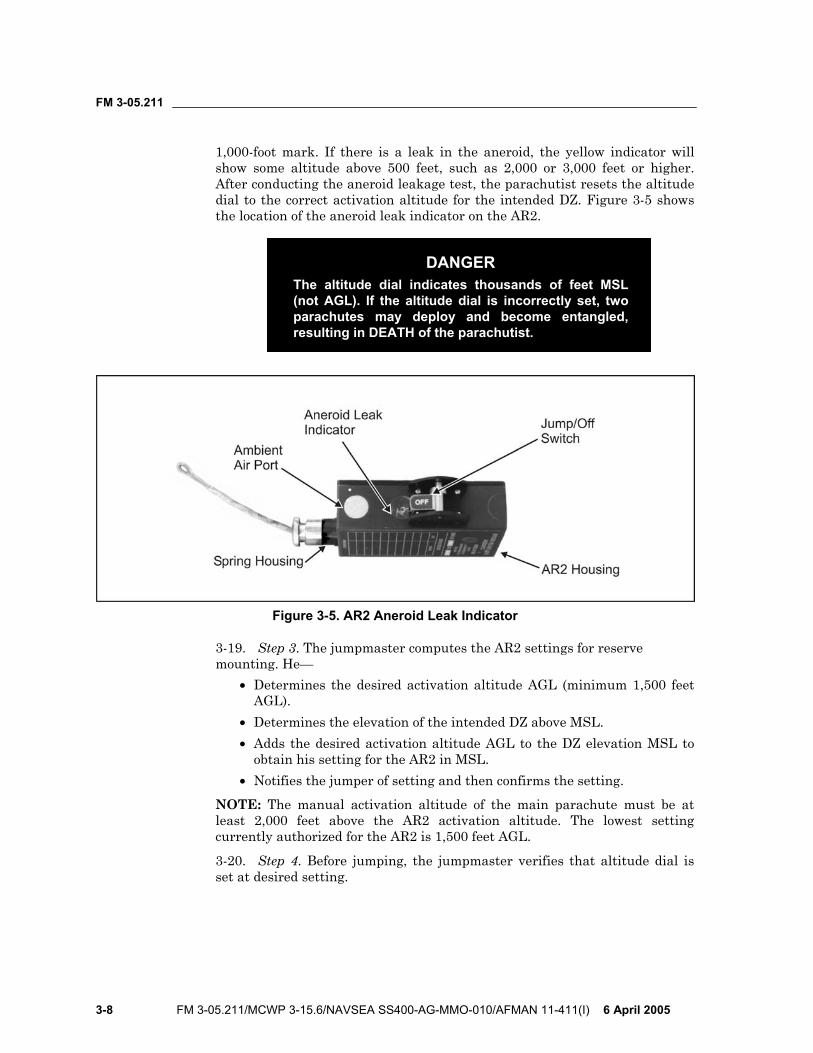
1,000-foot mark. If there is a leak in the aneroid, the yellow indicator will show some altitude above 500 feet, such as 2,000 or 3,000 feet or higher. After conducting the aneroid leakage test, the parachutist resets the altitude dial to the correct activation altitude for the intended DZ. Figure 3-5 shows the location of the aneroid leak indicator on the AR2.
DANGER The altitude dial indicates thousands of feet MSL (not AGL). If the altitude dial is incorrectly set, two parachutes may deploy and become entangled, resulting in DEATH of the parachutist.
Figure 3-5. AR2 Aneroid Leak Indicator
3-19. Step 3. The jumpmaster computes the AR2 settings for reserve mounting. He—
• Determines the desired activation altitude AGL (minimum 1,500 feet AGL).
• Determines the elevation of the intended DZ above MSL. • Adds the desired activation altitude AGL to the DZ elevation MSL to
obtain his setting for the AR2 in MSL. • Notifies the jumper of setting and then confirms the setting.
NOTE: The manual activation altitude of the main parachute must be at least 2,000 feet above the AR2 activation altitude. The lowest setting currently authorized for the AR2 is 1,500 feet AGL.
3-20. Step 4. Before jumping, the jumpmaster verifies that altitude dial is set at desired setting.
FM 3-05.211
6 April 2005 FM 3-05.211/MCWP 3-15.6/NAVSEA SS400-AG-MMO-010/AFMAN 11-411(I) 3-9
DANGER Parachutist must not move JUMP/OFF switch to the JUMP position unless the aircraft is at least 1,500 feet above the altitude set on the dial. The AR2 must remain well above the altitude set on the dial at all times after the JUMP/OFF switch has been moved to JUMP. If the altitude dial is incorrectly set, two parachutes may deploy and become entangled, resulting in DEATH of the parachutist.
3-21. Step 5. The parachutist moves JUMP/OFF switch to JUMP and verifies that the switch is all the way over to the detent position. 3-22. Step 6. After completing the jump, the parachutist moves the JUMP/OFF switch to OFF.
3-23. Step 7. With the JUMP/OFF switch in OFF position, the parachutist prepares the AR2 for the next jump by repeating steps 1 through 5.
DANGER Moving the JUMP/OFF switch to OFF repositions the mechanism for the next jump. If the switch is left in the JUMP position, the next jump will cause the AR2 to activate prematurely, causing deployment of two parachutes that may become entangled, resulting in DEATH of the parachutist.
AR2 BAROMETRIC CALCULATOR, MODEL 466-001 3-24. The AR2 barometric calculator was designed to compensate for altitude offsets caused by atmospheric pressure variations and thus provide more accurate AR2 dial settings. The calculator also makes it possible to accurately set both AR2s and wrist altimeters at locations remote from the DZ.
3-25. The barometric calculator has three selectable operational modes. These modes are explained below:
• Mode 1: Operator located at DZ. This is the simplest mode of operation and is the one in effect when the calculator is turned on. Only one input, the AR2 actuation altitude, is required for operation in this mode.
• Mode 2: Remote operation with DZ equivalent altitude available. This mode permits calculation of AR2 dial settings when the operator is at a location other than the DZ. In addition to knowing the AR2 actuation altitude, the equivalent altitude of the DZ must be obtained from someone at that location. Equivalent altitude may be determined from either another barometric calculator or from an aviation altimeter located on the ground at the DZ.
• Mode 3: Remote operation with DZ altimeter setting and elevation available. This mode is an alternate to Mode 2 when no calculator or
FM 3-05.211
3-10 FM 3-05.211/MCWP 3-15.6/NAVSEA SS400-AG-MMO-010/AFMAN 11-411(I) 6 April 2005
altimeter is available on the ground at the DZ. The local altimeter setting and MSL elevation of the DZ are necessary for operation in this mode.
3-26. Remote setting of wrist altimeters may be accomplished in either Mode 2 or Mode 3 using the same input information as that required for the AR2 dial setting. Employing the calculator to determine both settings assures that no altitude offset exists between the two devices. Barometric pressure changes that occur at the DZ between the time the AR2s and wrist altimeters are set and the time the jump is carried out will affect both settings by the same amount in the same direction. For this reason, remote settings should be made as close to the time of the jump as is practicable.
DESCRIPTION 3-27. The AR2 barometric calculator, Figure 3-6, page 3-11, is a hand-held, self-contained, battery-powered device that automatically measures the surrounding barometric pressure, calculates the necessary altitude offset, and provides an accurate revised setting for the AR2 altitude dial, rounded to the nearest 250-foot dial graduation. The calculator possesses the following characteristics and features:
• A rugged, compact, streamlined enclosure. • Redundant sensors with temperature compensation to measure the
surrounding atmospheric pressure. • An electronic microprocessor incorporating mathematical formulas to
convert the measured pressure to an equivalent altitude on the standard atmospheric pressure curve.
• Simple operation with input prompts and error messages. • A single required input value, the AR2 actuation altitude in feet AGL,
for operation at the DZ. • Automatic computation and display of the corrected altitude setting,
rounded to the nearest 250-foot graduation to facilitate setting the AR2 dial.
• Two alternate modes of operation when remote from the DZ, with capability for remote wrist altimeter setting.
• Display of the local equivalent MSL altitude. • Standard battery power with lighted display, automatic shutoff, and
low-battery indicator.
3-28. The nonnumeric keys on the keypad function as follows: • ON/OFF—Turns the calculator on or off. • MODE—Allows selection of remote operation modes and wrist
altimeter adjustment. • CLEAR—Allows changes or corrections to input values and resets the
calculator. • ENTER—Puts a newly keyed-in number into the calculator program
for computation and fixes it in the display.

FM 3-05.211
6 April 2005 FM 3-05.211/MCWP 3-15.6/NAVSEA SS400-AG-MMO-010/AFMAN 11-411(I) 3-11
• RUN—Causes the calculator to compute a setting for the AR2 dial or wrist altimeter, depending on the mode of operation.
• DATA—After dial-setting calculation, causes the display to show the present equivalent altitude of the calculator.
• LIGHT—Illuminates the display.
Figure 3-6. AR2 Barometric Calculator
DEFINITIONS 3-29. The following definitions will be helpful for correctly interpreting and implementing the operating instructions, which begin on page 3-13:
• Above ground level (AGL). Height above a surface referenced as zero, regardless of that surface’s actual MSL elevation.
• Actuation altitude (ACT ALT). The altitude above the DZ, in feet AGL, at which the AR2 functions to deploy the reserve parachute. This altitude should be at least 1,500 feet below the altitude at which the main parachute is fully deployed. The main parachute pull altitude must allow for this amount of separation.
• Altimeter setting (ALTM STG). The setting applied to an aircraft altimeter’s barometric correction counter that results in an altimeter reading equal to the MSL ground elevation of an airport, or other location, when the aircraft is sitting on the ground at that location.
FM 3-05.211
3-12 FM 3-05.211/MCWP 3-15.6/NAVSEA SS400-AG-MMO-010/AFMAN 11-411(I) 6 April 2005
• AR2 dial setting. The number of feet MSL to which the AR2 dial should be set to obtain the correct actuation altitude after DZ elevation and all barometric adjustments have been taken into account.
• Aviation (master) altimeter. An altimeter of the type installed in all aircraft. This instrument has an adjustment mechanism to provide offset corrections (altimeter settings) for local deviations from standard barometric pressure conditions.
• Barometric correction counter. The adjustment mechanism that allows an altimeter to be corrected for local deviations from standard pressure.
• DZ elevation (DZ ELEV). The actual physical (ground) altitude of the DZ, in feet MSL, obtained from topographic maps or a global positioning system (GPS).
• Equivalent altitude (EQUIVALENT ALT). The MSL altitude for a location, derived from the standard atmosphere pressure-altitude curve, which corresponds to the prevailing ambient pressure at that location. This parameter is computed by the barometric calculator and is used to bring locations with different atmospheric pressure variations to the same reference point. Depending on the prevailing pressure, equivalent altitude may be higher or lower than the actual ground elevation. Equivalent altitudes may be negative for locations at or near sea level. The equivalent altitude of any location may also be determined using an aviation altimeter by adjusting its barometric correction counter to the standard setting of 29.92 (no correction) and reading the altitude directly.
• Local barometric reference data. Information describing the atmospheric conditions presently surrounding the barometric calculator. When this data is accessed, the equivalent altitude of the calculator is displayed. The equivalent altitude of a calculator located at the DZ is used during Mode 2 operation to compute remote AR2 dial and wrist altimeter settings.
• Mean sea level (MSL). The average height of the sea for all tidal conditions; the zero altitude reference point used in determining ground elevations.
• Remote operation. Operation of the barometric calculator and resultant setting of AR2s and wrist altimeters at a location other than the DZ.
• Standard atmosphere. An idealized description of the average properties of the earth’s atmosphere, including the relationship between atmospheric pressure and altitude, based on a pressure of 29.92 inches of mercury (in Hg), or 1013 millibars (mb), at MSL. All aviation altimeters are calibrated to the standard atmosphere pressure-altitude curve to permit uniform adjustment under variable atmospheric and geographic conditions. The AR2 is also calibrated to the standard atmosphere.
• Wrist altimeter adjustment (WRIST ALTM ADJUSTMENT). In general, the practice of setting a wrist altimeter to zero on the ground at the DZ to permit determination of a jumper’s height AGL. The barometric calculator provides the capability for adjusting wrist
FM 3-05.211
6 April 2005 FM 3-05.211/MCWP 3-15.6/NAVSEA SS400-AG-MMO-010/AFMAN 11-411(I) 3-13
altimeters at a remote location to obtain a zero reading on the ground at the DZ.
• Wrist altimeter setting. The number of feet, AGL, to which a wrist altimeter at a remote location should be set to obtain a zero reading on the ground at the DZ.
OPERATION 3-30. The following paragraphs outline the steps taken in operating the calculator at various modes.
Mode 1: Operator Located at Drop Zone 3-31. The parachutist should perform the following steps:
• Step 1. Press ON/OFF to turn on the calculator. The calculator will perform self-tests when it is first turned on. If the temperature or altitude environment is outside the operating range of the calculator, or if the measurements from the two pressure sensors do not agree, the calculator will not function. The appropriate error message will appear in the display. Paragraph 3-37 outlines a listing and definition of all possible error messages.
• Step 2. (The words ACTUATION ALTITUDE will appear, blinking, in the first display line, and FT AGL will be displayed in the second line.) Key the desired actuation altitude for the AR2, in feet AGL, into the second display line and press ENTER. Both display lines will become steadily illuminated. The acceptable actuation altitude input range is 1,000 to 24,999 feet AGL. INPUT OUT OF RANGE will appear if the input value is not within these limits.
• Step 3. Press RUN. SET AR2 DIAL will appear in the third display line, and XXXXX FT MSL, the calculated dial setting rounded to the nearest 250 feet, will be displayed in the bottom line. The acceptable AR2 dial setting range is 500 to 25,000 feet MSL. SETTING OUT OF RANGE will appear if the calculated setting is not within these limits.
• Step 4. After the calculation is made, press DATA to obtain the local equivalent altitude. The message LOCAL BAROMETRIC REFERENCE DATA will appear in the first two lines of the display. EQUIVALENT ALTITUDE and XXXXX FT MSL will be displayed in the third and fourth lines, respectively. In Mode 1, this value is used to calculate the AR2 dial setting and is available only after RUN has been pressed and the calculation has been made.
• Step 5. Press DATA again to toggle back to the previous display readings.
• Step 6. Press CLEAR to correct input errors at any time or to reset the calculator.
• Step 7. Press ON/OFF to turn off the calculator.
FM 3-05.211
3-14 FM 3-05.211/MCWP 3-15.6/NAVSEA SS400-AG-MMO-010/AFMAN 11-411(I) 6 April 2005
Mode 2: Remote Operation With Drop Zone Equivalent Altitude Available
3-32. The parachutist should perform the following steps: • Step 1. Press ON/OFF to turn on the calculator. • Step 2. Press MODE once; DZ EQUIVALENT ALT will appear,
blinking, in the first display line and FT MSL will be displayed in the second line.
• Step 3. Obtain the present equivalent altitude at the DZ, in feet MSL, (not DZ ground elevation) from one of the two following sources:
A barometric calculator located on the ground at the DZ (refer to Mode 1 operation).
An aviation altimeter located on the ground at the DZ with its barometric correction counter set to 29.92 (1013 if calibrated in millibars).
Key this value into the second line and press ENTER. The acceptable DZ equivalent altitude input range is –2,000 to 16,000 feet MSL.
• Step 4. (The first two lines will become steadily illuminated and ACT ALT will blink in the third line.) Key the desired actuation altitude for the AR2, in feet AGL, into the third line and press ENTER. The acceptable actuation altitude input range is 1,000 to 24,999 feet AGL.
• Step 5. (The third line will become steadily illuminated.) Press RUN. SET AR2 XXXXX FT MSL will be displayed in the bottom line. The acceptable AR2 dial setting range is 500 to 25,000 feet MSL.
NOTE: Information on remote wrist altimeter adjustment is discussed in paragraph 3-34. • Step 6. After the calculation is made, press DATA to obtain the local
equivalent altitude. DATA works exactly the same as in Mode 1. However, the equivalent altitude displayed while in Mode 2 reflects the present location of the calculator and is not the information used to calculate the AR2 dial setting for the remote DZ.
• Step 7. Press CLEAR to correct input errors or reset the calculator. • Step 8. Press ON/OFF to turn off the calculator.
Mode 3: Remote Operation With Drop Zone Altimeter Setting and Elevation Available
3-33. The parachutist should perform the following steps: • Step 1. Press ON/OFF to turn on the calculator. • Step 2. Press MODE twice; DZ ALTM STG will appear, blinking, in the
first display line.

FM 3-05.211
6 April 2005 FM 3-05.211/MCWP 3-15.6/NAVSEA SS400-AG-MMO-010/AFMAN 11-411(I) 3-15
DANGER Moving the JUMP/OFF switch to OFF repositions the mechanism for the next jump. lf the switch is left in the JUMP position, the next jump will cause the AR2 to activate prematurely, causing deployment of two parachutes that may become entangled, resulting in DEATH of the parachutist.
• Step 3. Obtain the altimeter setting, in inches of mercury, at or close to the DZ from someone at that location. The parachutist keys this setting into the first line of the display using the format XX.XX IN and presses ENTER. (If the altimeter setting is given in millibars, he divides by 33.86 to get inches of mercury.) The acceptable altimeter setting input range is 28.10 to 31.00 inches of mercury.
• Step 4. (The first line of the display will become steadily illuminated and DZ ELEV will blink in the second line.) Key the actual ground elevation for the DZ, in feet MSL (not equivalent altitude as in Mode 2), into the second display line and press ENTER. The acceptable DZ elevation input range is 1,000 to 15,000 feet MSL.
• Step 5. (The second line of the display will become steadily illuminated and ACT ALT will blink in the third line.) Key the desired actuation altitude for the AR2, in feet AGL, into the third line and press ENTER. The acceptable actuation altitude input range is 1,000 to 24,999 feet AGL.
• Step 6. (The third line will become steadily illuminated.) Press RUN. SET AR2 XXXXX FT MSL will be displayed in the bottom line. The acceptable AR2 dial setting range is 500 to 25,000 feet MSL.
NOTE: Information on remote wrist altimeter adjustment is discussed in paragraph 3-34. • Step 7. After the calculation is made, press DATA to obtain the local
equivalent altitude. DATA works exactly the same as in Mode 1. However, the equivalent altitude displayed while in Mode 3 reflects the present location of the calculator and is not the information used to calculate the AR2 dial setting for the remote DZ.
• Step 8. Press CLEAR to correct input errors or reset the calculator. • Step 9. Press ON/OFF to turn off the calculator.
Remote Wrist Altimeter Adjustment in Mode 2 or Mode 3 3-34. This information can be accessed only after the AR2 dial setting calculation in Mode 2 or Mode 3 above has been made. The parachutist must not turn the calculator off before selecting the wrist altimeter adjustment mode.

FM 3-05.211
3-16 FM 3-05.211/MCWP 3-15.6/NAVSEA SS400-AG-MMO-010/AFMAN 11-411(I) 6 April 2005
WARNING To obtain an accurate adjustment, the calculator and wrist altimeters must be located in the same pressure environment during the calculation and adjustment procedure. The parachutist should set the wrist altimeters immediately. Local barometric pressure changes that occur between the time the calculation is made and the wrist altimeters are set may affect the accuracy of the setting. Remote calculations and settings should be made as close to the time of the jump as is practicable.
3-35. The parachutist should perform the following steps when setting the remote wrist altimeter adjustment in Mode 2 or Mode 3:
• Step 1. Press MODE once; WRIST ALTM ADJUSTMENT will appear in the first display line. The parachutist should note the following:
If the calculator is in Mode 2, DZ EQUIVALENT ALT and its previously input value will be displayed in the second and third lines, respectively.
If the calculator is in Mode 3, DZ ALTM STG and DZ ELEV, and their previously input values, will be displayed in the second and third lines, respectively.
• Step 2. Press RUN. SET WRIST ALTM XXXXX, the required adjustment in feet, will be displayed in the bottom line. NOTE: This number may be negative if the remote wrist altimeters are located at or below the MSL altitude of the DZ.
• Step 3. Press DATA, which displays the same information as in Mode 2 or Mode 3, respectively.
• Step 4. Press CLEAR to correct input errors or reset the calculator. • Step 5. Press ON/OFF to turn off the calculator.
LIGHTED DISPLAY 3-36. At any time while the barometric calculator is turned on, pressing LIGHT will illuminate its display. The display will remain lit until the calculator is turned off or automatically shuts itself off to conserve battery power.
AUTOMATIC SHUTOFF 3-37. If no key is pressed for approximately 5 minutes, the calculator will automatically shut itself off to conserve battery power. The parachutist presses ON/OFF to return the calculator to service.
FM 3-05.211
6 April 2005 FM 3-05.211/MCWP 3-15.6/NAVSEA SS400-AG-MMO-010/AFMAN 11-411(I) 3-17
ERROR MESSAGES 3-38. The following error messages may appear during operation of the barometric calculator:
• LOW BATTERY. Appears if the battery voltage is insufficient to operate the unit. If this message appears, the parachutist should replace the battery before attempting to use the calculator.
• UNIT INOPERABLE. Appears if the two pressure sensors do not agree or if there is a malfunction of other electrical components inside the unit. If this message persists after several on/off cycles, the unit is defective and must be repaired. Only the manufacturer can repair the calculator.
• ALT OUT OF LIMITS. Appears if the ambient pressure measured by the sensors corresponds to an altitude greater than approximately 20,000 feet. The calculator will function normally when transported to a lower altitude.
• TEMP OUT OF LIMITS. Appears if the temperature inside the calculator housing is less than 10 degrees Fahrenheit (F) or greater than 130 degrees F. The calculator will function normally when its temperature is brought back within this range.
• INPUT OUT OF RANGE. Appears in the appropriate line of the display if a number outside the acceptable input range is keyed in and ENTER is pressed.
• SETTING OUT OF RANGE. Appears in the bottom line of the display when RUN is pressed if the setting calculated by the program is outside the range of the AR2 dial.
MAINTENANCE 3-39. Maintenance for the barometric calculator consists of periodically verifying the accuracy of its sensors, changing the battery when necessary, and keeping the unit free from dirt and other contaminants. Parachutists must not drop the calculator or subject it to rough handling. The calculator should be kept in its protective case when not in use.
3-40. If the calculator will be out of service for 180 days or more, the battery should be removed.
ACCURACY VERIFICATION 3-41. The altitude accuracy of the calculator should be verified every 120 days. Verification is most easily accomplished by using the Model 467 Wrist Altimeter Test Chamber (WATC) in conjunction with the Model 453 Electronic Test Chamber (ETC) and following the procedure described below. The parachutist—
• Connects the Model 467 WATC to the Model 453 ETC using the hose assembly supplied with the WATC, and then closes the lids of both chambers.
• Plugs the power cord of the ETC into the correct power outlet and switches it on. Allows the ETC to warm up for at least 30 minutes.
FM 3-05.211
3-18 FM 3-05.211/MCWP 3-15.6/NAVSEA SS400-AG-MMO-010/AFMAN 11-411(I) 6 April 2005
Verifies that the two units together will hold a set altitude; for example, 2,000 feet above the local ground elevation.
• Prepares the calculator so that it displays the real-time local equivalent altitude. To display this altitude, the parachutist—
Runs a hypothetical test case in Mode 1 and obtains any valid AR2 dial setting.
Presses and holds the – key, and then presses and holds DATA. Releases – first, then releases DATA. The local equivalent altitude
will be displayed, and its value will change as the altitude of the calculator changes.
• Returns the altitude to ground level, opens the lid of the WATC, and places the calculator inside one of the compartments; closes the lid.
• Sets the ETC’s altimeter to zero (0) feet, + 10 feet. NOTE: If this altitude is lower than the local ambient altitude, it may be necessary to clamp or weight the lids of both chambers so that they can contain the required pressure. The parachutist uses care to avoid damaging the chambers.
• Allows the altitude to stabilize and notes the equivalent altitude displayed on the calculator—it should be within 100 feet of the ETC altimeter reading.
• Repeats the above two steps at 2,000, 4,000, 8,000, 12,000, and 16,000 feet. Each calculator reading should be within 100 feet of the corresponding ETC altimeter reading. If the calculator shuts off during this process, the parachutist removes it from the WATC, obtains the local equivalent altitude as before, and continues the test. If any of the corresponding readings differ from each other by more than 100 feet, the calculator is defective and must be repaired.
BATTERY REPLACEMENT 3-42. Parachutists must replace the battery immediately whenever LOW BATTERY appears in the display. To replace the battery, the parachutist—
• Turns off the calculator.
CAUTION
Parachutists must not attempt to open the calculator unless it is in a flat position with the top half uppermost.
• Turns the calculator over to access six disassembly screws. The parachutist uses finger pressure to hold the two halves of the case together while removing the screws, then turns the case back over to place the top half uppermost.
FM 3-05.211
6 April 2005 FM 3-05.211/MCWP 3-15.6/NAVSEA SS400-AG-MMO-010/AFMAN 11-411(I) 3-19
WARNING Parachutists must not tamper with internal components of the calculator in any manner; inaccurate readings could result.
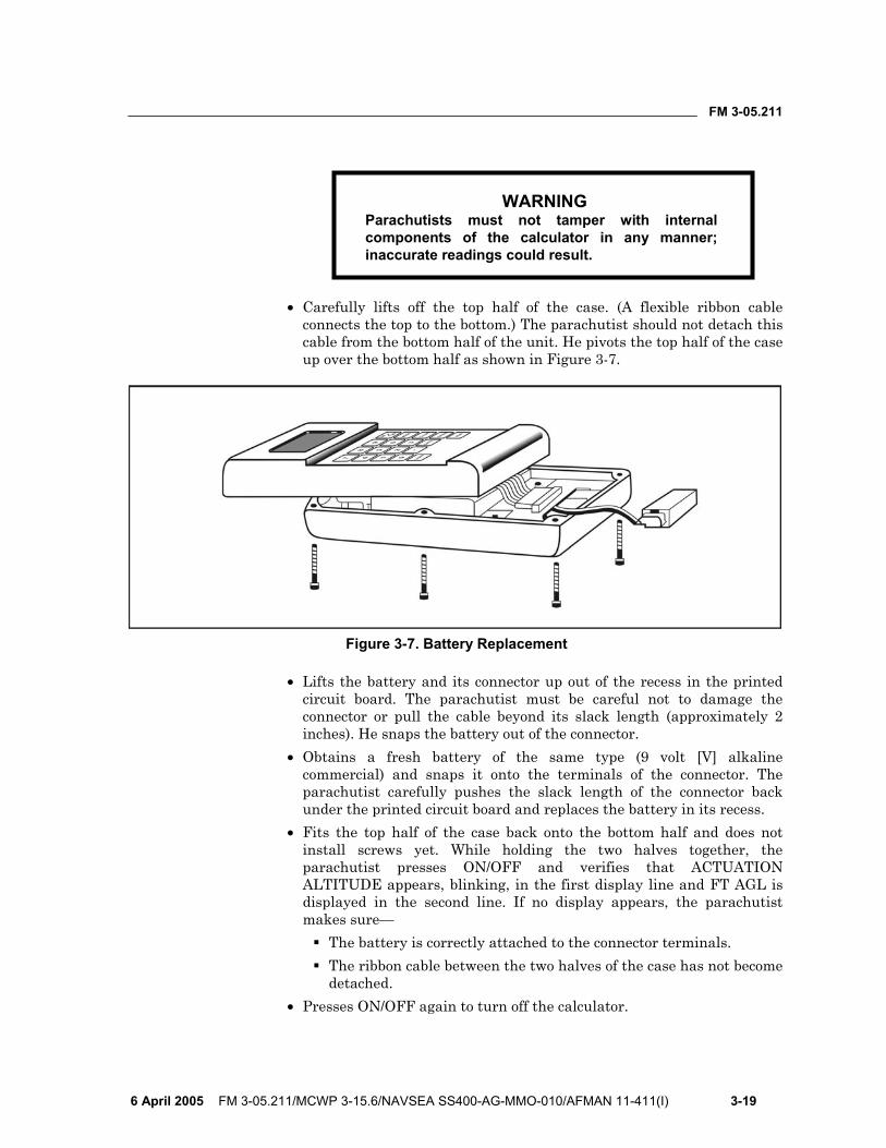
• Carefully lifts off the top half of the case. (A flexible ribbon cable connects the top to the bottom.) The parachutist should not detach this cable from the bottom half of the unit. He pivots the top half of the case up over the bottom half as shown in Figure 3-7.
Figure 3-7. Battery Replacement
• Lifts the battery and its connector up out of the recess in the printed circuit board. The parachutist must be careful not to damage the connector or pull the cable beyond its slack length (approximately 2 inches). He snaps the battery out of the connector.
• Obtains a fresh battery of the same type (9 volt [V] alkaline commercial) and snaps it onto the terminals of the connector. The parachutist carefully pushes the slack length of the connector back under the printed circuit board and replaces the battery in its recess.
• Fits the top half of the case back onto the bottom half and does not install screws yet. While holding the two halves together, the parachutist presses ON/OFF and verifies that ACTUATION ALTITUDE appears, blinking, in the first display line and FT AGL is displayed in the second line. If no display appears, the parachutist makes sure—
The battery is correctly attached to the connector terminals. The ribbon cable between the two halves of the case has not become
detached. • Presses ON/OFF again to turn off the calculator.

FM 3-05.211
3-20 FM 3-05.211/MCWP 3-15.6/NAVSEA SS400-AG-MMO-010/AFMAN 11-411(I) 6 April 2005
• Maintains finger pressure to hold the two halves of the case together while reinstalling the assembly screws. The parachutist must use care in tightening the screws. The parachutist may find it helpful to place a finger against the case joint to feel the amount of clearance remaining between the two halves as each screw is tightened.
CAUTION
Parachutists must not overtighten screws. Stripped threads may render the calculator unserviceable.
CLEANING 3-43. Parachutists clean the exterior surfaces of the calculator using a clean cloth dampened with water and, if necessary, a little mild soap. They do not use solvents or immerse the calculator in water or other liquids.
SENTINEL MK 2100 3-44. The Sentinel MK 2100 automatic emergency parachute release system (Figure 3-8) is precision engineered to provide automatic emergency opening of the parachute pack assembly. Altitude and rate of descent sensing capability combined with reliable solid-state electronic circuitry provide completely automatic operation while in the air. The electronic circuitry supplies the power to the explosive detonating cartridge. When the explosive cartridge fires, powerful expanding gases drive the actuating piston within the power actuating cylinder with ample force and movement to extract the pins from the locking cones on the reserve parachute. Properly calibrated, the Sentinel MK 2100 can accurately sense the preset actuation altitude of 1,000 feet to 20,000 feet.
Figure 3-8. Sentinel MK 2100
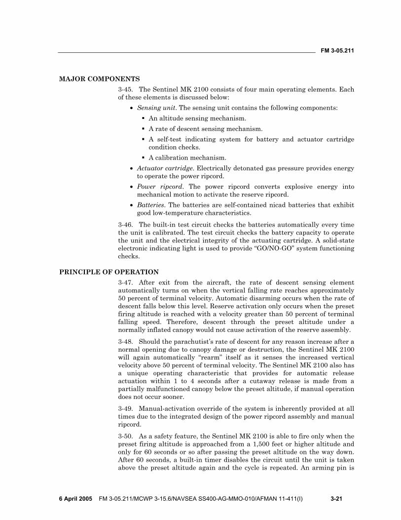
FM 3-05.211
6 April 2005 FM 3-05.211/MCWP 3-15.6/NAVSEA SS400-AG-MMO-010/AFMAN 11-411(I) 3-21
MAJOR COMPONENTS 3-45. The Sentinel MK 2100 consists of four main operating elements. Each of these elements is discussed below:
• Sensing unit. The sensing unit contains the following components: An altitude sensing mechanism. A rate of descent sensing mechanism. A self-test indicating system for battery and actuator cartridge
condition checks. A calibration mechanism.
• Actuator cartridge. Electrically detonated gas pressure provides energy to operate the power ripcord.
• Power ripcord. The power ripcord converts explosive energy into mechanical motion to activate the reserve ripcord.
• Batteries. The batteries are self-contained nicad batteries that exhibit good low-temperature characteristics.
3-46. The built-in test circuit checks the batteries automatically every time the unit is calibrated. The test circuit checks the battery capacity to operate the unit and the electrical integrity of the actuating cartridge. A solid-state electronic indicating light is used to provide “GO/NO-GO” system functioning checks.
PRINCIPLE OF OPERATION 3-47. After exit from the aircraft, the rate of descent sensing element automatically turns on when the vertical falling rate reaches approximately 50 percent of terminal velocity. Automatic disarming occurs when the rate of descent falls below this level. Reserve activation only occurs when the preset firing altitude is reached with a velocity greater than 50 percent of terminal falling speed. Therefore, descent through the preset altitude under a normally inflated canopy would not cause activation of the reserve assembly.
3-48. Should the parachutist’s rate of descent for any reason increase after a normal opening due to canopy damage or destruction, the Sentinel MK 2100 will again automatically “rearm” itself as it senses the increased vertical velocity above 50 percent of terminal velocity. The Sentinel MK 2100 also has a unique operating characteristic that provides for automatic release actuation within 1 to 4 seconds after a cutaway release is made from a partially malfunctioned canopy below the preset altitude, if manual operation does not occur sooner.
3-49. Manual-activation override of the system is inherently provided at all times due to the integrated design of the power ripcord assembly and manual ripcord.
3-50. As a safety feature, the Sentinel MK 2100 is able to fire only when the preset firing altitude is approached from a 1,500 feet or higher altitude and only for 60 seconds or so after passing the preset altitude on the way down. After 60 seconds, a built-in timer disables the circuit until the unit is taken above the preset altitude again and the cycle is repeated. An arming pin is
FM 3-05.211
3-22 FM 3-05.211/MCWP 3-15.6/NAVSEA SS400-AG-MMO-010/AFMAN 11-411(I) 6 April 2005
provided to completely disable the sensing unit and must be removed prior to exit to enable proper operation.
SAFETY CONSIDERATIONS 3-51. An operational cartridge light indicates only that the electrical output and wiring circuitry, up to and including the cartridge, is operational. It does not ensure that the explosive charge is good.
3-52. A visual inspection of the charge before use is the only way to verify whether the charge has been fired. (On occasion, it is possible for a fired cartridge to still light the cartridge light.) This visual check should be considered mandatory due to critical use of the Sentinel MK 2100 as lifesaving equipment.
3-53. If anything appears abnormal or out of the ordinary when calibrating or using the MK 2100, parachutists discontinue its use and return it for repairs immediately.
3-54. If the jump is aborted for any reason, the arming pin must be reinserted. This action is taken to avoid any possibility of the unit firing in a rapidly descending aircraft.
3-55. Parachutists avoid operating the Sentinel MK 2100 unnecessarily. It is an emergency system and should be treated as such.
3-56. During cold weather jumping, parachutists check the battery’s condition prior to exit to determine if the lower temperature at jump altitude has degraded the battery’s capacity to activate the cartridge.
MILITARY CYPRES 3-57. The Military CYPRES is an automatic activation device that meets the needs and requirements of MFF operations (HALO and HAHO). The Military CYPRES senses the rate of fall and altitude (AGL) by the use of pressure relation of the set default altitude above a DZ (training mode), or a programmed virtual DZ (operational mode) by means of setting a calculated pressure setting in millibars into the CYPRES unit. When the CYPRES falls through the altitude window set above the DZ, either actual or virtual, at a rate of fall at or beyond the default speed of the CYPRES, the CYPRES will activate. The explosive-powered cutter assembly will activate electronically and sever the reserve parachute’s special-made continuous closing loop to allow positive opening of the reserve pack assembly. If the rate of fall is slower than the set default speed, the CYPRES will not actuate.
COMPONENTS 3-58. The Military CYPRES has only three components—the control unit, the processing unit, and the release unit. The Military CYPRES system is water resistant for 15 minutes at a depth of 15 feet and is encased in a robust case with rounded corners and edges.
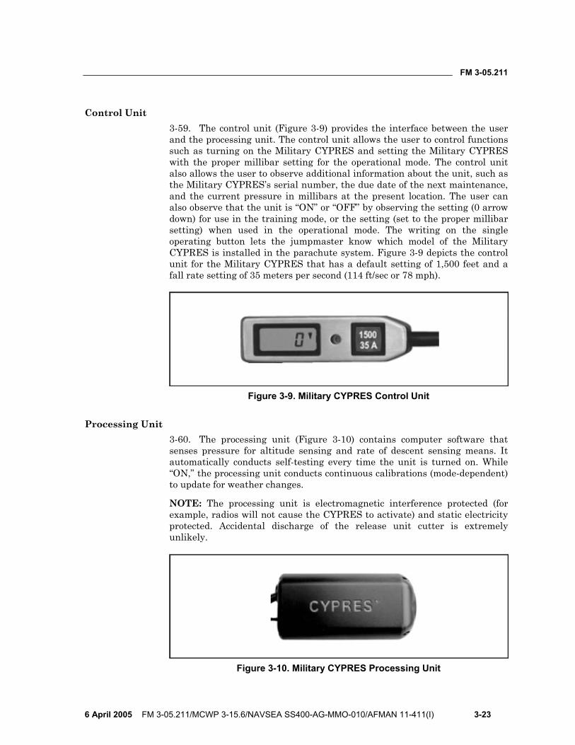
FM 3-05.211
6 April 2005 FM 3-05.211/MCWP 3-15.6/NAVSEA SS400-AG-MMO-010/AFMAN 11-411(I) 3-23
Control Unit 3-59. The control unit (Figure 3-9) provides the interface between the user and the processing unit. The control unit allows the user to control functions such as turning on the Military CYPRES and setting the Military CYPRES with the proper millibar setting for the operational mode. The control unit also allows the user to observe additional information about the unit, such as the Military CYPRES’s serial number, the due date of the next maintenance, and the current pressure in millibars at the present location. The user can also observe that the unit is “ON” or “OFF” by observing the setting (0 arrow down) for use in the training mode, or the setting (set to the proper millibar setting) when used in the operational mode. The writing on the single operating button lets the jumpmaster know which model of the Military CYPRES is installed in the parachute system. Figure 3-9 depicts the control unit for the Military CYPRES that has a default setting of 1,500 feet and a fall rate setting of 35 meters per second (114 ft/sec or 78 mph).
Figure 3-9. Military CYPRES Control Unit
Processing Unit 3-60. The processing unit (Figure 3-10) contains computer software that senses pressure for altitude sensing and rate of descent sensing means. It automatically conducts self-testing every time the unit is turned on. While “ON,” the processing unit conducts continuous calibrations (mode-dependent) to update for weather changes.
NOTE: The processing unit is electromagnetic interference protected (for example, radios will not cause the CYPRES to activate) and static electricity protected. Accidental discharge of the release unit cutter is extremely unlikely.
Figure 3-10. Military CYPRES Processing Unit
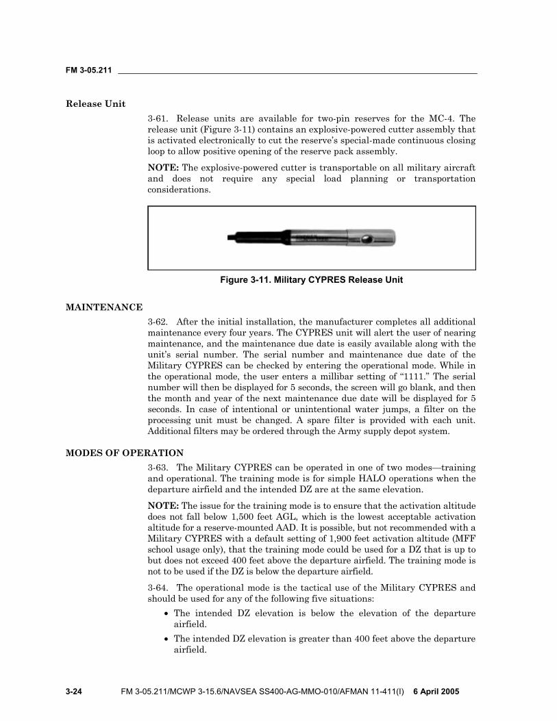
FM 3-05.211
3-24 FM 3-05.211/MCWP 3-15.6/NAVSEA SS400-AG-MMO-010/AFMAN 11-411(I) 6 April 2005
Release Unit 3-61. Release units are available for two-pin reserves for the MC-4. The release unit (Figure 3-11) contains an explosive-powered cutter assembly that is activated electronically to cut the reserve’s special-made continuous closing loop to allow positive opening of the reserve pack assembly.
NOTE: The explosive-powered cutter is transportable on all military aircraft and does not require any special load planning or transportation considerations.
Figure 3-11. Military CYPRES Release Unit
MAINTENANCE 3-62. After the initial installation, the manufacturer completes all additional maintenance every four years. The CYPRES unit will alert the user of nearing maintenance, and the maintenance due date is easily available along with the unit’s serial number. The serial number and maintenance due date of the Military CYPRES can be checked by entering the operational mode. While in the operational mode, the user enters a millibar setting of “1111.” The serial number will then be displayed for 5 seconds, the screen will go blank, and then the month and year of the next maintenance due date will be displayed for 5 seconds. In case of intentional or unintentional water jumps, a filter on the processing unit must be changed. A spare filter is provided with each unit. Additional filters may be ordered through the Army supply depot system.
MODES OF OPERATION 3-63. The Military CYPRES can be operated in one of two modes—training and operational. The training mode is for simple HALO operations when the departure airfield and the intended DZ are at the same elevation.
NOTE: The issue for the training mode is to ensure that the activation altitude does not fall below 1,500 feet AGL, which is the lowest acceptable activation altitude for a reserve-mounted AAD. It is possible, but not recommended with a Military CYPRES with a default setting of 1,900 feet activation altitude (MFF school usage only), that the training mode could be used for a DZ that is up to but does not exceed 400 feet above the departure airfield. The training mode is not to be used if the DZ is below the departure airfield.
3-64. The operational mode is the tactical use of the Military CYPRES and should be used for any of the following five situations:
• The intended DZ elevation is below the elevation of the departure airfield.
• The intended DZ elevation is greater than 400 feet above the departure airfield.
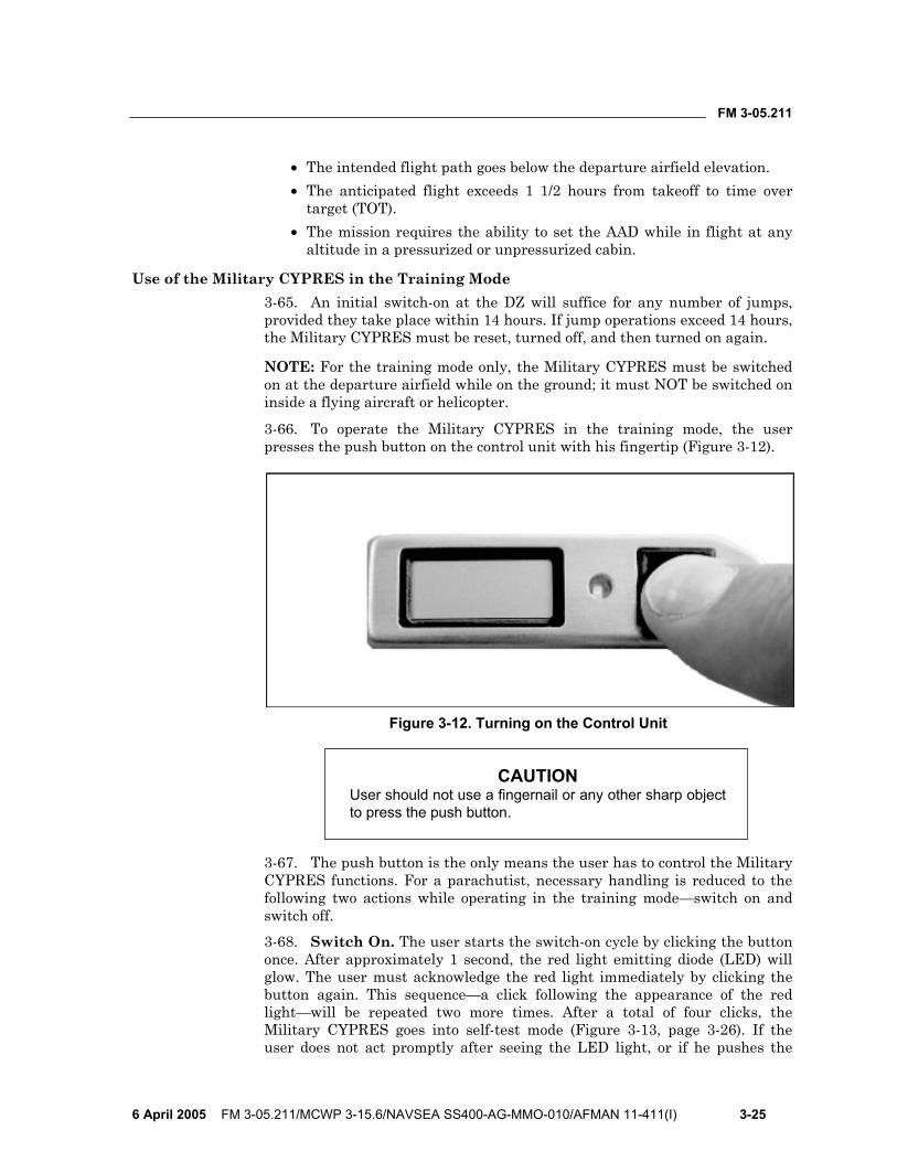
FM 3-05.211
6 April 2005 FM 3-05.211/MCWP 3-15.6/NAVSEA SS400-AG-MMO-010/AFMAN 11-411(I) 3-25
• The intended flight path goes below the departure airfield elevation. • The anticipated flight exceeds 1 1/2 hours from takeoff to time over
target (TOT). • The mission requires the ability to set the AAD while in flight at any
altitude in a pressurized or unpressurized cabin.
Use of the Military CYPRES in the Training Mode 3-65. An initial switch-on at the DZ will suffice for any number of jumps, provided they take place within 14 hours. If jump operations exceed 14 hours, the Military CYPRES must be reset, turned off, and then turned on again.
NOTE: For the training mode only, the Military CYPRES must be switched on at the departure airfield while on the ground; it must NOT be switched on inside a flying aircraft or helicopter.
3-66. To operate the Military CYPRES in the training mode, the user presses the push button on the control unit with his fingertip (Figure 3-12).
Figure 3-12. Turning on the Control Unit
CAUTION User should not use a fingernail or any other sharp object to press the push button.
3-67. The push button is the only means the user has to control the Military CYPRES functions. For a parachutist, necessary handling is reduced to the following two actions while operating in the training mode—switch on and switch off. 3-68. Switch On. The user starts the switch-on cycle by clicking the button once. After approximately 1 second, the red light emitting diode (LED) will glow. The user must acknowledge the red light immediately by clicking the button again. This sequence—a click following the appearance of the red light—will be repeated two more times. After a total of four clicks, the Military CYPRES goes into self-test mode (Figure 3-13, page 3-26). If the user does not act promptly after seeing the LED light, or if he pushes the
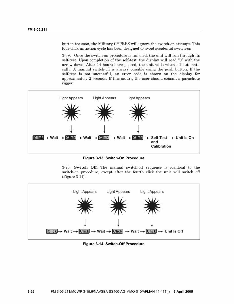
FM 3-05.211
3-26 FM 3-05.211/MCWP 3-15.6/NAVSEA SS400-AG-MMO-010/AFMAN 11-411(I) 6 April 2005
button too soon, the Military CYPRES will ignore the switch-on attempt. This four-click initiation cycle has been designed to avoid accidental switch-on.
3-69. Once the switch-on procedure is finished, the unit will run through its self-test. Upon completion of the self-test, the display will read “0” with the arrow down. After 14 hours have passed, the unit will switch off automati-cally. A manual switch-off is always possible using the push button. If the self-test is not successful, an error code is shown on the display for approximately 2 seconds. If this occurs, the user should consult a parachute rigger.
Figure 3-13. Switch-On Procedure
3-70. Switch Off. The manual switch-off sequence is identical to the switch-on procedure, except after the fourth click the unit will switch off (Figure 3-14).
Figure 3-14. Switch-Off Procedure
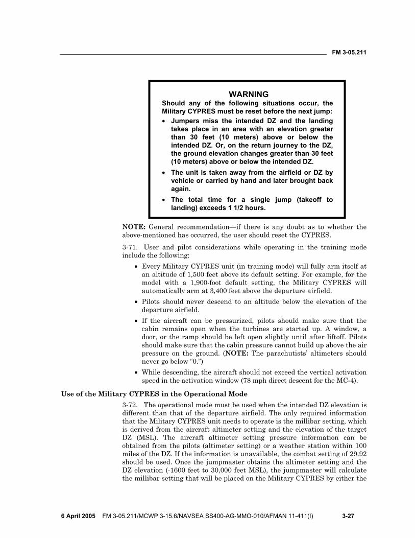
FM 3-05.211
6 April 2005 FM 3-05.211/MCWP 3-15.6/NAVSEA SS400-AG-MMO-010/AFMAN 11-411(I) 3-27
WARNING Should any of the following situations occur, the Military CYPRES must be reset before the next jump: • Jumpers miss the intended DZ and the landing
takes place in an area with an elevation greater than 30 feet (10 meters) above or below the intended DZ. Or, on the return journey to the DZ, the ground elevation changes greater than 30 feet (10 meters) above or below the intended DZ.
• The unit is taken away from the airfield or DZ by vehicle or carried by hand and later brought back again.
• The total time for a single jump (takeoff to landing) exceeds 1 1/2 hours.
NOTE: General recommendation—if there is any doubt as to whether the above-mentioned has occurred, the user should reset the CYPRES.
3-71. User and pilot considerations while operating in the training mode include the following:
• Every Military CYPRES unit (in training mode) will fully arm itself at an altitude of 1,500 feet above its default setting. For example, for the model with a 1,900-foot default setting, the Military CYPRES will automatically arm at 3,400 feet above the departure airfield.
• Pilots should never descend to an altitude below the elevation of the departure airfield.
• If the aircraft can be pressurized, pilots should make sure that the cabin remains open when the turbines are started up. A window, a door, or the ramp should be left open slightly until after liftoff. Pilots should make sure that the cabin pressure cannot build up above the air pressure on the ground. (NOTE: The parachutists’ altimeters should never go below “0.”)
• While descending, the aircraft should not exceed the vertical activation speed in the activation window (78 mph direct descent for the MC-4).
Use of the Military CYPRES in the Operational Mode 3-72. The operational mode must be used when the intended DZ elevation is different than that of the departure airfield. The only required information that the Military CYPRES unit needs to operate is the millibar setting, which is derived from the aircraft altimeter setting and the elevation of the target DZ (MSL). The aircraft altimeter setting pressure information can be obtained from the pilots (altimeter setting) or a weather station within 100 miles of the DZ. If the information is unavailable, the combat setting of 29.92 should be used. Once the jumpmaster obtains the altimeter setting and the DZ elevation (-1600 feet to 30,000 feet MSL), the jumpmaster will calculate the millibar setting that will be placed on the Military CYPRES by either the
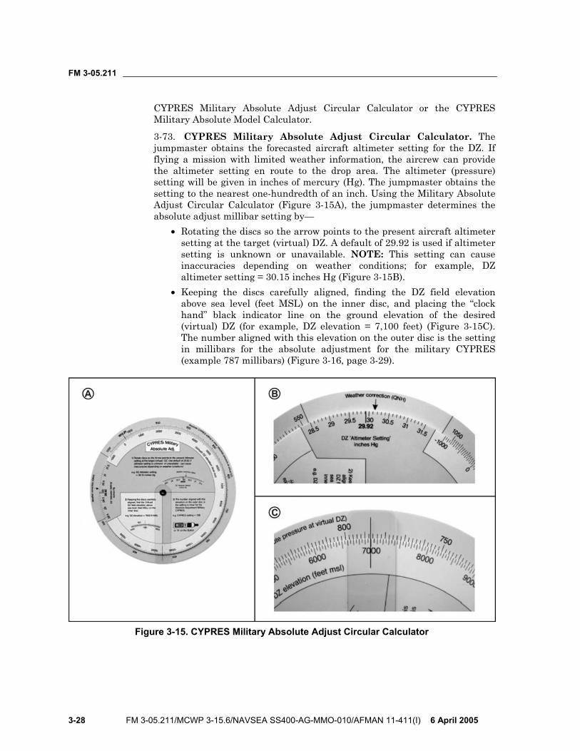
FM 3-05.211
3-28 FM 3-05.211/MCWP 3-15.6/NAVSEA SS400-AG-MMO-010/AFMAN 11-411(I) 6 April 2005
CYPRES Military Absolute Adjust Circular Calculator or the CYPRES Military Absolute Model Calculator.
3-73. CYPRES Military Absolute Adjust Circular Calculator. The jumpmaster obtains the forecasted aircraft altimeter setting for the DZ. If flying a mission with limited weather information, the aircrew can provide the altimeter setting en route to the drop area. The altimeter (pressure) setting will be given in inches of mercury (Hg). The jumpmaster obtains the setting to the nearest one-hundredth of an inch. Using the Military Absolute Adjust Circular Calculator (Figure 3-15A), the jumpmaster determines the absolute adjust millibar setting by—
• Rotating the discs so the arrow points to the present aircraft altimeter setting at the target (virtual) DZ. A default of 29.92 is used if altimeter setting is unknown or unavailable. NOTE: This setting can cause inaccuracies depending on weather conditions; for example, DZ altimeter setting = 30.15 inches Hg (Figure 3-15B).
• Keeping the discs carefully aligned, finding the DZ field elevation above sea level (feet MSL) on the inner disc, and placing the “clock hand” black indicator line on the ground elevation of the desired (virtual) DZ (for example, DZ elevation = 7,100 feet) (Figure 3-15C). The number aligned with this elevation on the outer disc is the setting in millibars for the absolute adjustment for the military CYPRES (example 787 millibars) (Figure 3-16, page 3-29).
Figure 3-15. CYPRES Military Absolute Adjust Circular Calculator

FM 3-05.211
6 April 2005 FM 3-05.211/MCWP 3-15.6/NAVSEA SS400-AG-MMO-010/AFMAN 11-411(I) 3-29
Figure 3-16. Example of Military CYPRES Control Unit Setting
3-74. CYPRES Military Absolute Adjust Model Calculator. To use this calculator (Figure 3-17), the jumpmaster—
• Enters the altimeter setting of the intended DZ or the aircraft altimeter setting (in either Hg or millibars).
• Enters the DZ elevation (MSL). • Selects from the drop down box the elevation scale (either feet or
meters). • Clicks the ‘Calculate!’ button.
The value for the CYPRES setting is then displayed in the box.
Figure 3-17. CYPRES Military Absolute Adjust Model Calculator
3-75. To operate the Military CYPRES in the operational mode, the user presses the push button on the control unit. The push button is the only means the user has to control the Military CYPRES functions. For a parachutist, necessary handling is reduced to the following four actions while operating in the operational mode:
• Switch on. • Increase altitude reference.
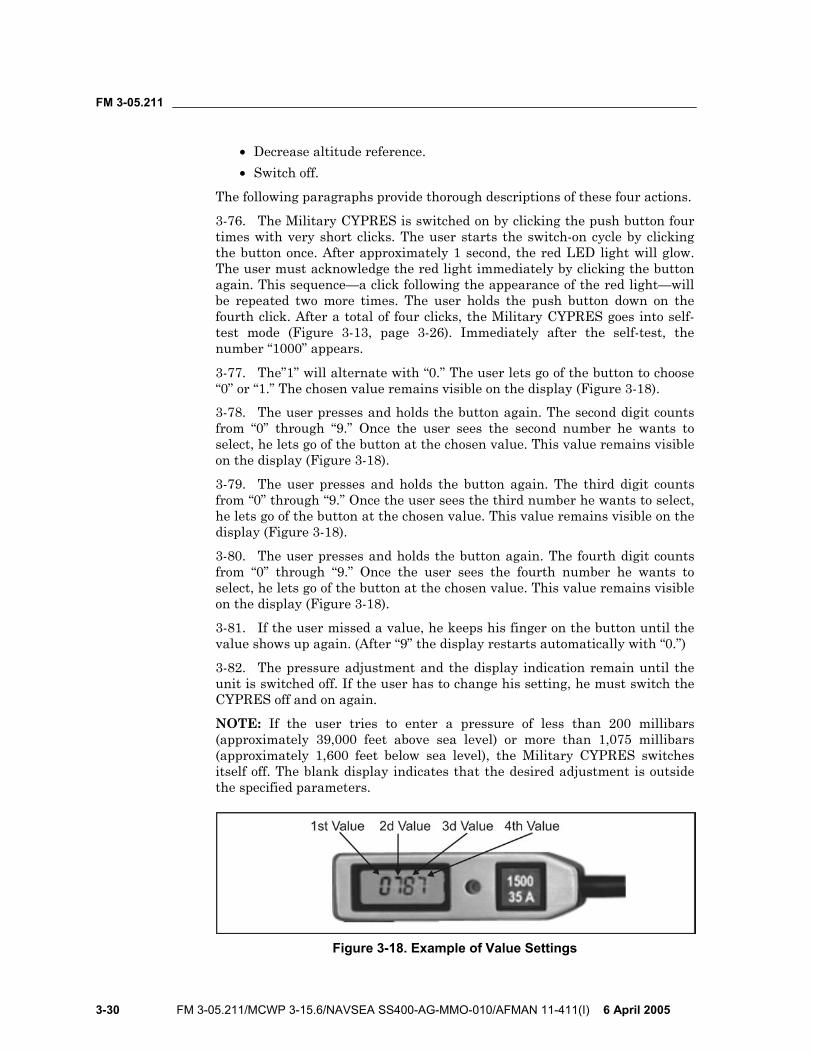
FM 3-05.211
3-30 FM 3-05.211/MCWP 3-15.6/NAVSEA SS400-AG-MMO-010/AFMAN 11-411(I) 6 April 2005
• Decrease altitude reference. • Switch off.
The following paragraphs provide thorough descriptions of these four actions.
3-76. The Military CYPRES is switched on by clicking the push button four times with very short clicks. The user starts the switch-on cycle by clicking the button once. After approximately 1 second, the red LED light will glow. The user must acknowledge the red light immediately by clicking the button again. This sequence—a click following the appearance of the red light—will be repeated two more times. The user holds the push button down on the fourth click. After a total of four clicks, the Military CYPRES goes into self-test mode (Figure 3-13, page 3-26). Immediately after the self-test, the number “1000” appears.
3-77. The”1” will alternate with “0.” The user lets go of the button to choose “0” or “1.” The chosen value remains visible on the display (Figure 3-18). 3-78. The user presses and holds the button again. The second digit counts from “0” through “9.” Once the user sees the second number he wants to select, he lets go of the button at the chosen value. This value remains visible on the display (Figure 3-18).
3-79. The user presses and holds the button again. The third digit counts from “0” through “9.” Once the user sees the third number he wants to select, he lets go of the button at the chosen value. This value remains visible on the display (Figure 3-18).
3-80. The user presses and holds the button again. The fourth digit counts from “0” through “9.” Once the user sees the fourth number he wants to select, he lets go of the button at the chosen value. This value remains visible on the display (Figure 3-18).
3-81. If the user missed a value, he keeps his finger on the button until the value shows up again. (After “9” the display restarts automatically with “0.”)
3-82. The pressure adjustment and the display indication remain until the unit is switched off. If the user has to change his setting, he must switch the CYPRES off and on again.
NOTE: If the user tries to enter a pressure of less than 200 millibars (approximately 39,000 feet above sea level) or more than 1,075 millibars (approximately 1,600 feet below sea level), the Military CYPRES switches itself off. The blank display indicates that the desired adjustment is outside the specified parameters.
Figure 3-18. Example of Value Settings

FM 3-05.211
6 April 2005 FM 3-05.211/MCWP 3-15.6/NAVSEA SS400-AG-MMO-010/AFMAN 11-411(I) 3-31
3-83. User and pilot considerations while operating in the operational mode include the following:
• Every Military CYPRES unit (in operational mode) will fully arm itself when the millibar setting is inputted into the control unit.
• Descent to an altitude below the elevation of departure airfield will not affect the Military CYPRES in the operational mode.
• When operating in the operational mode, the Military CYPRES can be set in a pressurized or depressurized aircraft while in flight.
• While descending, the aircraft should not exceed the vertical activation speed in the activation window (78 mph direct descent for the MC-4).
• The pilot should maintain a climb rate of no more than 1,000 feet per minute (ft/min) if depressurized or a steady pressurized rate within 1,000 ft/min if pressurized.

This page intentionally left blank.
FM 3-05.211
6 April 2005 FM 3-05.211/MCWP 3-15.6/NAVSEA SS400-AG-MMO-010/AFMAN 11-411(I) 4-1
Chapter 4
Use of Oxygen in Support of Military Free-Fall Operations
MFF parachuting is physically demanding. It exposes the parachutist to temperature extremes, rapid pressure changes, and long exposures at altitudes requiring supplemental oxygen. To prepare for this environment, the MFF parachutist must be thoroughly familiar with the physiological effects of oxygen, oxygen use, and the operation of oxygen equipment. All personnel participating in MFF operations must meet the physiological training requirements outlined in Appendix B, regardless of altitude and type of aircraft used.
PHYSIOLOGICAL EFFECTS OF HIGH-ALTITUDE MILITARY FREE-FALL OPERATIONS
4-1. Most physiological effects of high-altitude MFF operations fall into the category of pressure-change hazards. These hazards usually include various physiological symptoms. Based on Class C physiological mishaps since 1984, the most common types have been sinus blocks and ear blocks, hypoxia, decompression sickness, and hyperventilation. Each of these is discussed in the following paragraphs. Procedures for physiological and oxygen equipment-related emergencies are also discussed.
SINUS BLOCKS AND EAR BLOCKS 4-2. Sinus blocks and ear blocks normally occur when an MFF parachutist jumps with a head cold or some other type of upper respiratory illness. Sinus blocks and ear blocks usually occur during free-fall descent or during aircraft pressurization. Performing a Valsalva maneuver as the parachutist feels his ears getting “full” can clear most ear blocks. A Valsalva maneuver may clear a sinus block but may require additional medical attention. Use of nasal sprays may alleviate the symptoms associated with sinus and ear blocks.
HYPOXIA 4-3. Hypoxia is a condition caused by lack of oxygen. A reduction in the partial pressure of oxygen in the atmosphere occurs as the parachutist ascends. When the parachutist inhales, he receives fewer oxygen molecules. The reduction of the partial pressure inhibits the body’s ability to transfer oxygen to the tissues. The most common symptoms of hypoxia are blurred or tunnel vision, color blindness, dizziness, headache, nausea, numbness, tingling, euphoria, belligerence, loss of coordination, and lack of good judgment. Corrective action for a parachutist who becomes hypoxic is to place him on 100 percent oxygen and inform the aircraft commander. In extreme cases, it may be necessary to descend the aircraft and evacuate the
FM 3-05.211
4-2 FM 3-05.211/MCWP 3-15.6/NAVSEA SS400-AG-MMO-010/AFMAN 11-411(I) 6 April 2005
parachutist to the nearest medical facility. If hypoxia goes unrecognized and uncorrected, it can result in seizures, unconsciousness, or even death.
DECOMPRESSION SICKNESS 4-4. Decompression sickness (DCS) is a condition caused by the release of nitrogen from body tissues. DCS usually occurs during unpressurized flights above 18,000 feet MSL, but can occur at lower altitudes. Many factors contribute to DCS. Facial hair can cause an insufficient seal of the oxygen mask to the parachutist’s face, rendering prebreathing ineffective. Poor physical conditioning and fatigue will make the individual more susceptible to DCS. Alcohol use dehydrates the body, constricting the capillaries and decreasing the efficiency of the cardiovascular system. Nicotine from tobacco use hardens arteries and restricts blood flow to the capillaries, reducing the efficiency of the cardiovascular system. Smoking also reduces the efficiency of the lungs.
4-5. There are four types of DCS: the bends, chokes, neurological (central nervous system) hits, and skin manifestations. Each of these is discussed in the following paragraphs.
The Bends 4-6. The bends are the most common type of DCS. The most frequent symptom is a deep, dull, and penetrating pain in major movable joints that can increase to agonizing intensity. This pain may be significant enough to make the parachutist feel as if he cannot move the joint. The affected parachutist might also go into shock. Corrective action for a parachutist who experiences the bends is to—
• Place him on 100 percent oxygen. • Inform the aircraft commander. • Descend the aircraft and pressurize the cabin to as close to sea level as
possible. • Evacuate to the nearest medical facility with a recompression chamber.
A flight surgeon or aero medical examiner will determine if compression therapy is required.
The Chokes
4-7. The chokes are a rare but potentially life-threatening form of DCS. They are similar to the bends, but occur in the smaller blood vessels of the lungs, resulting in poor gas exchange and oxygenation of the blood. The most common symptoms are a deep, sharp pain near the breastbone; a dry, nonproductive cough; the inability to take a normal breath; a feeling of suffocation and apprehension; and possible shock symptoms, such as sweating, fainting, and cyanosis. Corrective action for a parachutist who experiences the chokes is the same as that stated in paragraph 4-6.
Neurological Hits 4-8. Neurological hits occur in extreme cases of DCS when the central nervous system becomes affected. The affected parachutist may experience
FM 3-05.211
6 April 2005 FM 3-05.211/MCWP 3-15.6/NAVSEA SS400-AG-MMO-010/AFMAN 11-411(I) 4-3
vision disturbances, headaches, partial paralysis, loss of orientation, delirium, and vertigo. Corrective action for a parachutist who experiences a central nervous system hit is the same as that stated in paragraph 4-6.
Skin Manifestations or Paresthesia 4-9. Skin manifestations or paresthesia is caused by nitrogen bubbles forming at the subcutaneous layer of the skin. The most common symptoms are itching, hot and cold flashes, a creepy feeling or gritty sensation, mottled reddish or purplish rash, and a tingling feeling of the affected area. Corrective action for a parachutist who experiences any of these symptoms is to—
• Place him on 100 percent oxygen. • Keep him from scratching or exercising the affected area. • Inform the aircraft commander.
4-10. Normally, the condition will dissipate upon descent. However, if the parachutist is incapacitated due to the condition, further corrective action is to—
• Descend the aircraft and pressurize the cabin to as close to sea level as possible.
• Evacuate to a medical facility with a recompression chamber. A flight surgeon or aero medical examiner will determine if compression therapy is required.
HYPERVENTILATION 4-11. Hyperventilation is a condition characterized by abnormal shallow and rapid breathing. Fear, anxiety, stress, intense concentration, or pain normally causes hyperventilation. Symptoms are similar to hypoxia and include lightheadedness, visual impairment, dizziness, numbness and tingling of the extremities, and loss of coordination and judgment. Personnel should conduct the following corrective actions:
• Calm the parachutist and have him talk, which will make him reduce his rate and depth of breathing. The goal is to achieve a breathing rate of 12 to 16 breaths per minute.
• Because of the similarity to hypoxia, continue or place him on 100 percent oxygen.
• Inform the aircraft commander. • Reevaluate the parachutist’s conscious state. If he is not responsive,
treat the situation as an in-flight emergency and evacuate the parachutist to the nearest medical facility.
PHYSIOLOGICAL AND OXYGEN EQUIPMENT-RELATED EMERGENCIES 4-12. Procedures for physiological and oxygen equipment-related emergencies are discussed below. Personnel should—
• For in-flight emergencies, make sure the jumpmaster, oxygen safety, and aircraft commander (also United States Air Force [USAF]
FM 3-05.211
4-4 FM 3-05.211/MCWP 3-15.6/NAVSEA SS400-AG-MMO-010/AFMAN 11-411(I) 6 April 2005
physiological technician if flight is above 18,000 feet MSL) are made aware of the problem.
• Ensure that the parachutist is receiving 100 percent oxygen from the console, the walk-around bottle, or an onboard aircraft regulator.
• Attempt to establish communications with the parachutist. Identify the problem and take corrective actions, to include immobilizing the affected areas, if possible.
• If the problem becomes progressive or severe, inform the aircraft commander of the nature of the problem and declare an in-flight emergency.
• Descend the aircraft and pressurize the cabin to as close to sea level as possible.
• Evacuate to a medical facility with a recompression chamber. A flight surgeon or aero medical examiner will determine if compression therapy is required.
4-13. Parachutists should be aware of the symptoms of DCS and monitor themselves on return to the ground. Some parachutists may have symptoms of DCS during flight that they do not notice due to discomfort from the parachute and equipment worn or that they do not report. Although these symptoms usually resolve themselves upon returning to ground, some personnel may continue to have symptoms. These personnel require prompt medical evaluation since their illness is more severe.
OXYGEN FORMS 4-14. Oxygen is an odorless, colorless, tasteless gas that makes up 21 percent of the atmosphere. The remaining atmosphere consists of 78 percent nitrogen and 1 percent of other trace gases. There are four types of oxygen in use today—aviation, medical, welding, and research. Aviation oxygen is the only one suitable for MFF operations. The following paragraphs discuss the various forms of aviator’s oxygen and their associated containers.
GASEOUS OXYGEN 4-15. Gaseous aviator’s breathing oxygen is designated Grade A, Type I, Military Specification MIL-0-27210E. No other manufactured oxygen is acceptable. The difference between aviator’s and medical or technical (welder’s) oxygen is the absence of water vapor. The purity requirement for aviator’s oxygen is 99.5 percent by volume. It may not contain more than 0.005 milligram of water vapor per liter at 760 millimeters of mercury at 68 degrees F. It must be odorless and free from contaminants, including drying agents. The other types of oxygen may be adequate for breathing, but they usually contain excessive water vapor that, with the temperature drop encountered at altitude, could freeze and restrict the flow of oxygen through the oxygen system the parachutist uses. The two types of gaseous aviator’s breathing oxygen are as follows:
• Gaseous-low pressure. Low-pressure aviator’s breathing oxygen is stored in yellow, lightweight, shatterproof cylinders. These cylinders are filled to a maximum pressure of 450 psi; however, they are

FM 3-05.211
6 April 2005 FM 3-05.211/MCWP 3-15.6/NAVSEA SS400-AG-MMO-010/AFMAN 11-411(I) 4-5
normally filled in the range of 400 to 450 psi. They are considered empty when they reach 100 psi. If a cylinder is stored at a pressure less than 50 psi for more than 2 hours, it must be purged because of the water condensation that forms.
• Gaseous-high pressure. High-pressure aviator’s breathing oxygen is stored in lime green, heavyweight, shatterproof bottles stenciled with AVIATOR’S BREATHING OXYGEN. These bottles can be filled to a maximum pressure of 2,200 psi; however, they are normally filled in the range of 1,800 to 2,200 psi.
LIQUID OXYGEN 4-16. Liquid aviator’s breathing oxygen is designated Grade B, Type II, Military Specification MIL-0-27210E. The most common use of liquid oxygen is in storage facilities and for aircraft oxygen supplies because a large quantity can be carried in a small space.
OXYGEN REQUIREMENTS 4-17. The lower density of oxygen at high altitude causes many physiological problems. For this reason, MFF parachutists and aircrews need additional oxygen. Table 4-1, page 4-6, contains USAF-established requirements for supplemental oxygen for the MFF parachutist during unpressurized flight. Air Force Instruction (AFI) 11-409, High Altitude Airdrop Mission Support Program, outlines these requirements. The following briefly describe the requirements:
• All personnel will prebreathe 100 percent oxygen at or below 10,000 feet MSL pressure or cabin altitude below 10,000 feet MSL pressure on any mission scheduled for a drop at or above 18,000 feet MSL.
• The required prebreathing time will be completed before the 20-minute warning and before the cabin altitude ascends through 10,000 feet MSL.
• Any break in prebreathing requires restarting the prebreathing period or removing the individuals whose prebreathing was interrupted from the mission.
• Prebreathing requires the presence of an Air Force physiological technician onboard the aircraft.
• All personnel onboard during unpressurized operations above 10,000 feet MSL and higher will use oxygen. (Exception: Parachutists may operate without supplemental oxygen during unpressurized flights up to 13,000 feet MSL provided the time above 10,000 feet MSL does not exceed 30 minutes each sortie.)
4-18. MFF parachuting is physically demanding. The higher jump altitudes associated with MFF operations expose the body to rapid pressure changes that require the use of supplemental oxygen. As a result, the MFF parachutist must—
• Conduct no more than two oxygen jumps between 13,000 and 17,999 feet in a 24-hour period.
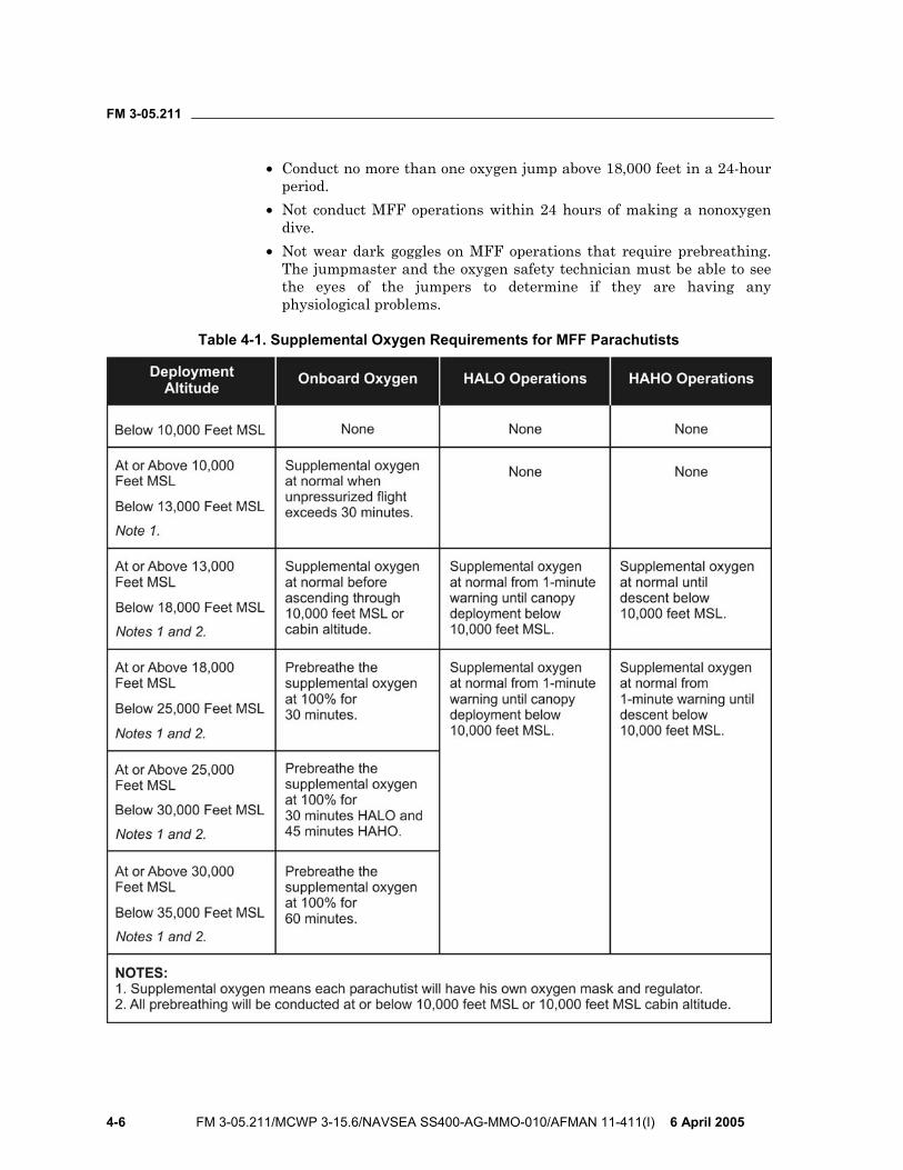
FM 3-05.211
4-6 FM 3-05.211/MCWP 3-15.6/NAVSEA SS400-AG-MMO-010/AFMAN 11-411(I) 6 April 2005
• Conduct no more than one oxygen jump above 18,000 feet in a 24-hour period.
• Not conduct MFF operations within 24 hours of making a nonoxygen dive.
• Not wear dark goggles on MFF operations that require prebreathing. The jumpmaster and the oxygen safety technician must be able to see the eyes of the jumpers to determine if they are having any physiological problems.
Table 4-1. Supplemental Oxygen Requirements for MFF Parachutists
FM 3-05.211
6 April 2005 FM 3-05.211/MCWP 3-15.6/NAVSEA SS400-AG-MMO-010/AFMAN 11-411(I) 4-7
OXYGEN LIFE-SUPPORT EQUIPMENT 4-19. Life-support equipment consists of the oxygen mask, the portable bailout oxygen system with the AIROX VIII assembly, the six-man prebreather portable oxygen system, the MA-1 portable oxygen assembly, and the prebreather attachment. This equipment is discussed in the paragraphs below.
OXYGEN MASK 4-20. The oxygen mask is designed to be worn with parachutist helmets that have bayonet lug receivers for the mask’s harness assembly. Oxygen enters the face piece through the valve located at the front of the mask. Exhaled air passes out through the same valve. The construction of the valve’s exhalation port allows a pressure of only 1 millimeter of mercury greater than the pressure of the oxygen being supplied by the regulator to force open the valve and allow exhaled air to pass to the atmosphere. A 17.5-inch-long convoluted silicone hose with a 3/4-inch internal diameter attaches to the mask. Inside the hose is an antistretch cord that prevents extreme stretching and hose separation during free fall. The mask has an integral microphone that adapts to the aircraft’s communication system.
WARNING Commercial sunblock, camouflage paint, and lip balm used by MFF parachutists can cause oxygen burns and flash burns when using nonmilitary-approved petroleum, oil, and lubricant products with oxygen.
Types of Oxygen Masks 4-21. There are several types of oxygen masks currently in use. The most common of these masks are described below.
4-22. MBU-5/P. The MBU-5/P pressure-demand oxygen mask has been a military standard for more than 15 years (Figure 4-1, page 4-8). It has a soft, pliable silicone rubber face piece with a separate plastic outer shell. Four face piece sizes are available.
4-23. MBU-12/P. The MBU-12/P pressure-demand oxygen mask is a replacement for the MBU-5/P mask (Figure 4-2, page 4-9). It has a soft, supple silicone rubber face piece integrally bonded to a plastic hard shell. It seals firmly during pressure breathing. It comes in four sizes to provide proper fit and superior comfort during extended wear. The lower profile design and four-point suspension are more stable than the MBU-5P mask during free fall. Antiroll webs at the nose seal prevent downward roll-off. The integral face piece and hard shell design permit good downward vision and increased head mobility.
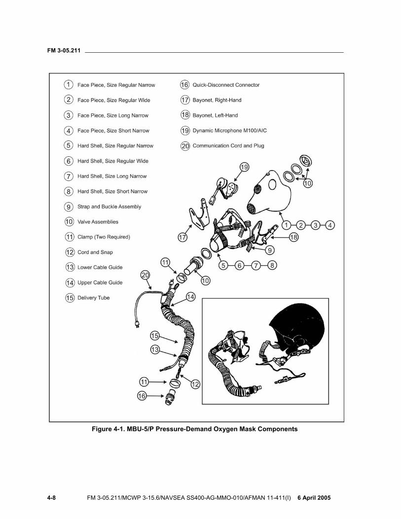
FM 3-05.211
4-8 FM 3-05.211/MCWP 3-15.6/NAVSEA SS400-AG-MMO-010/AFMAN 11-411(I) 6 April 2005
Figure 4-1. MBU-5/P Pressure-Demand Oxygen Mask Components
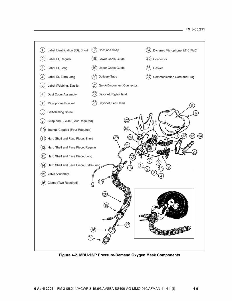
FM 3-05.211
6 April 2005 FM 3-05.211/MCWP 3-15.6/NAVSEA SS400-AG-MMO-010/AFMAN 11-411(I) 4-9
Figure 4-2. MBU-12/P Pressure-Demand Oxygen Mask Components
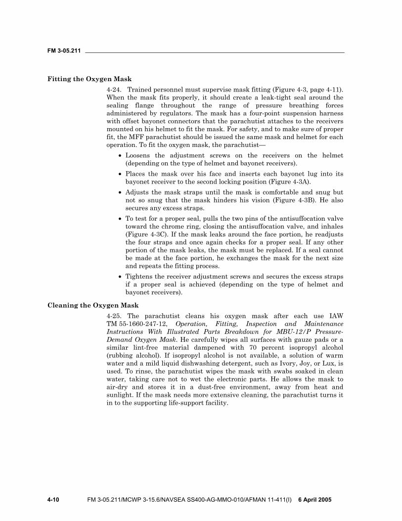
FM 3-05.211
4-10 FM 3-05.211/MCWP 3-15.6/NAVSEA SS400-AG-MMO-010/AFMAN 11-411(I) 6 April 2005
Fitting the Oxygen Mask 4-24. Trained personnel must supervise mask fitting (Figure 4-3, page 4-11). When the mask fits properly, it should create a leak-tight seal around the sealing flange throughout the range of pressure breathing forces administered by regulators. The mask has a four-point suspension harness with offset bayonet connectors that the parachutist attaches to the receivers mounted on his helmet to fit the mask. For safety, and to make sure of proper fit, the MFF parachutist should be issued the same mask and helmet for each operation. To fit the oxygen mask, the parachutist—
• Loosens the adjustment screws on the receivers on the helmet (depending on the type of helmet and bayonet receivers).
• Places the mask over his face and inserts each bayonet lug into its bayonet receiver to the second locking position (Figure 4-3A).
• Adjusts the mask straps until the mask is comfortable and snug but not so snug that the mask hinders his vision (Figure 4-3B). He also secures any excess straps.
• To test for a proper seal, pulls the two pins of the antisuffocation valve toward the chrome ring, closing the antisuffocation valve, and inhales (Figure 4-3C). If the mask leaks around the face portion, he readjusts the four straps and once again checks for a proper seal. If any other portion of the mask leaks, the mask must be replaced. If a seal cannot be made at the face portion, he exchanges the mask for the next size and repeats the fitting process.
• Tightens the receiver adjustment screws and secures the excess straps if a proper seal is achieved (depending on the type of helmet and bayonet receivers).
Cleaning the Oxygen Mask 4-25. The parachutist cleans his oxygen mask after each use IAW TM 55-1660-247-12, Operation, Fitting, Inspection and Maintenance Instructions With Illustrated Parts Breakdown for MBU-12/P Pressure-Demand Oxygen Mask. He carefully wipes all surfaces with gauze pads or a similar lint-free material dampened with 70 percent isopropyl alcohol (rubbing alcohol). If isopropyl alcohol is not available, a solution of warm water and a mild liquid dishwashing detergent, such as Ivory, Joy, or Lux, is used. To rinse, the parachutist wipes the mask with swabs soaked in clean water, taking care not to wet the electronic parts. He allows the mask to air-dry and stores it in a dust-free environment, away from heat and sunlight. If the mask needs more extensive cleaning, the parachutist turns it in to the supporting life-support facility.
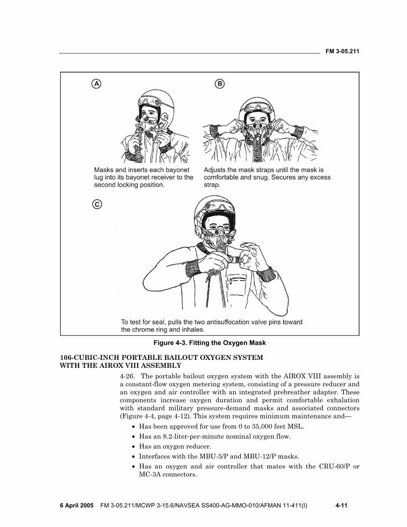
FM 3-05.211
6 April 2005 FM 3-05.211/MCWP 3-15.6/NAVSEA SS400-AG-MMO-010/AFMAN 11-411(I) 4-11
Figure 4-3. Fitting the Oxygen Mask
106-CUBIC-INCH PORTABLE BAILOUT OXYGEN SYSTEM WITH THE AIROX VIII ASSEMBLY
4-26. The portable bailout oxygen system with the AIROX VIII assembly is a constant-flow oxygen metering system, consisting of a pressure reducer and an oxygen and air controller with an integrated prebreather adapter. These components increase oxygen duration and permit comfortable exhalation with standard military pressure-demand masks and associated connectors (Figure 4-4, page 4-12). This system requires minimum maintenance and—
• Has been approved for use from 0 to 35,000 feet MSL. • Has an 8.2-liter-per-minute nominal oxygen flow. • Has an oxygen reducer. • Interfaces with the MBU-5/P and MBU-12/P masks. • Has an oxygen and air controller that mates with the CRU-60/P or
MC-3A connectors.
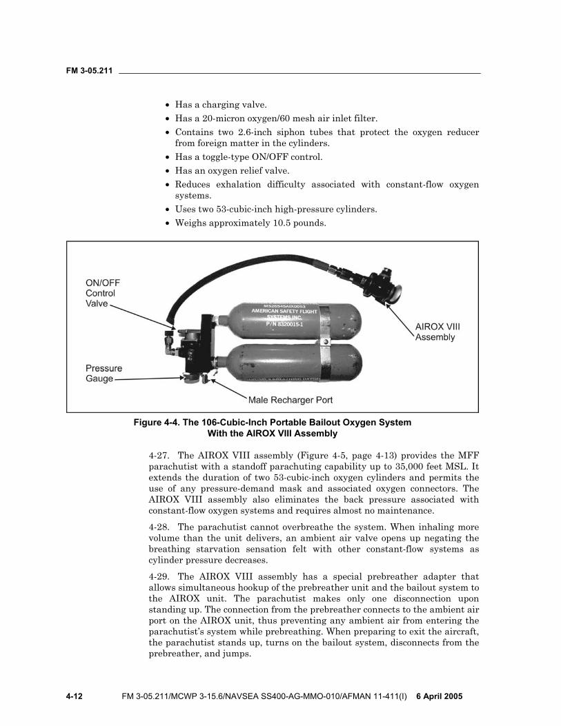
FM 3-05.211
4-12 FM 3-05.211/MCWP 3-15.6/NAVSEA SS400-AG-MMO-010/AFMAN 11-411(I) 6 April 2005
• Has a charging valve. • Has a 20-micron oxygen/60 mesh air inlet filter. • Contains two 2.6-inch siphon tubes that protect the oxygen reducer
from foreign matter in the cylinders. • Has a toggle-type ON/OFF control. • Has an oxygen relief valve. • Reduces exhalation difficulty associated with constant-flow oxygen
systems. • Uses two 53-cubic-inch high-pressure cylinders. • Weighs approximately 10.5 pounds.
Figure 4-4. The 106-Cubic-Inch Portable Bailout Oxygen System With the AIROX VIII Assembly
4-27. The AIROX VIII assembly (Figure 4-5, page 4-13) provides the MFF parachutist with a standoff parachuting capability up to 35,000 feet MSL. It extends the duration of two 53-cubic-inch oxygen cylinders and permits the use of any pressure-demand mask and associated oxygen connectors. The AIROX VIII assembly also eliminates the back pressure associated with constant-flow oxygen systems and requires almost no maintenance.
4-28. The parachutist cannot overbreathe the system. When inhaling more volume than the unit delivers, an ambient air valve opens up negating the breathing starvation sensation felt with other constant-flow systems as cylinder pressure decreases.
4-29. The AIROX VIII assembly has a special prebreather adapter that allows simultaneous hookup of the prebreather unit and the bailout system to the AIROX unit. The parachutist makes only one disconnection upon standing up. The connection from the prebreather connects to the ambient air port on the AIROX unit, thus preventing any ambient air from entering the parachutist’s system while prebreathing. When preparing to exit the aircraft, the parachutist stands up, turns on the bailout system, disconnects from the prebreather, and jumps.
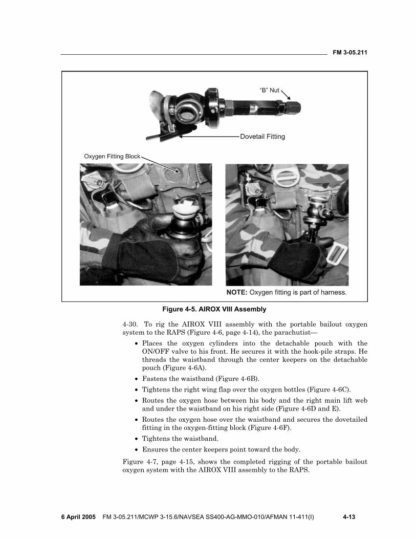
FM 3-05.211
6 April 2005 FM 3-05.211/MCWP 3-15.6/NAVSEA SS400-AG-MMO-010/AFMAN 11-411(I) 4-13
Figure 4-5. AIROX VIII Assembly
4-30. To rig the AIROX VIII assembly with the portable bailout oxygen system to the RAPS (Figure 4-6, page 4-14), the parachutist—
• Places the oxygen cylinders into the detachable pouch with the ON/OFF valve to his front. He secures it with the hook-pile straps. He threads the waistband through the center keepers on the detachable pouch (Figure 4-6A).
• Fastens the waistband (Figure 4-6B). • Tightens the right wing flap over the oxygen bottles (Figure 4-6C). • Routes the oxygen hose between his body and the right main lift web
and under the waistband on his right side (Figure 4-6D and E). • Routes the oxygen hose over the waistband and secures the dovetailed
fitting in the oxygen-fitting block (Figure 4-6F). • Tightens the waistband. • Ensures the center keepers point toward the body.
Figure 4-7, page 4-15, shows the completed rigging of the portable bailout oxygen system with the AIROX VIII assembly to the RAPS.
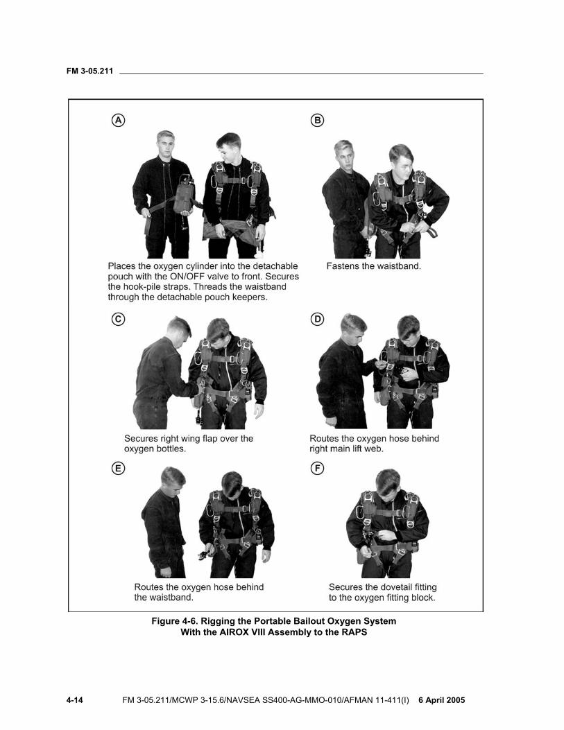
FM 3-05.211
4-14 FM 3-05.211/MCWP 3-15.6/NAVSEA SS400-AG-MMO-010/AFMAN 11-411(I) 6 April 2005
Figure 4-6. Rigging the Portable Bailout Oxygen System With the AIROX VIII Assembly to the RAPS
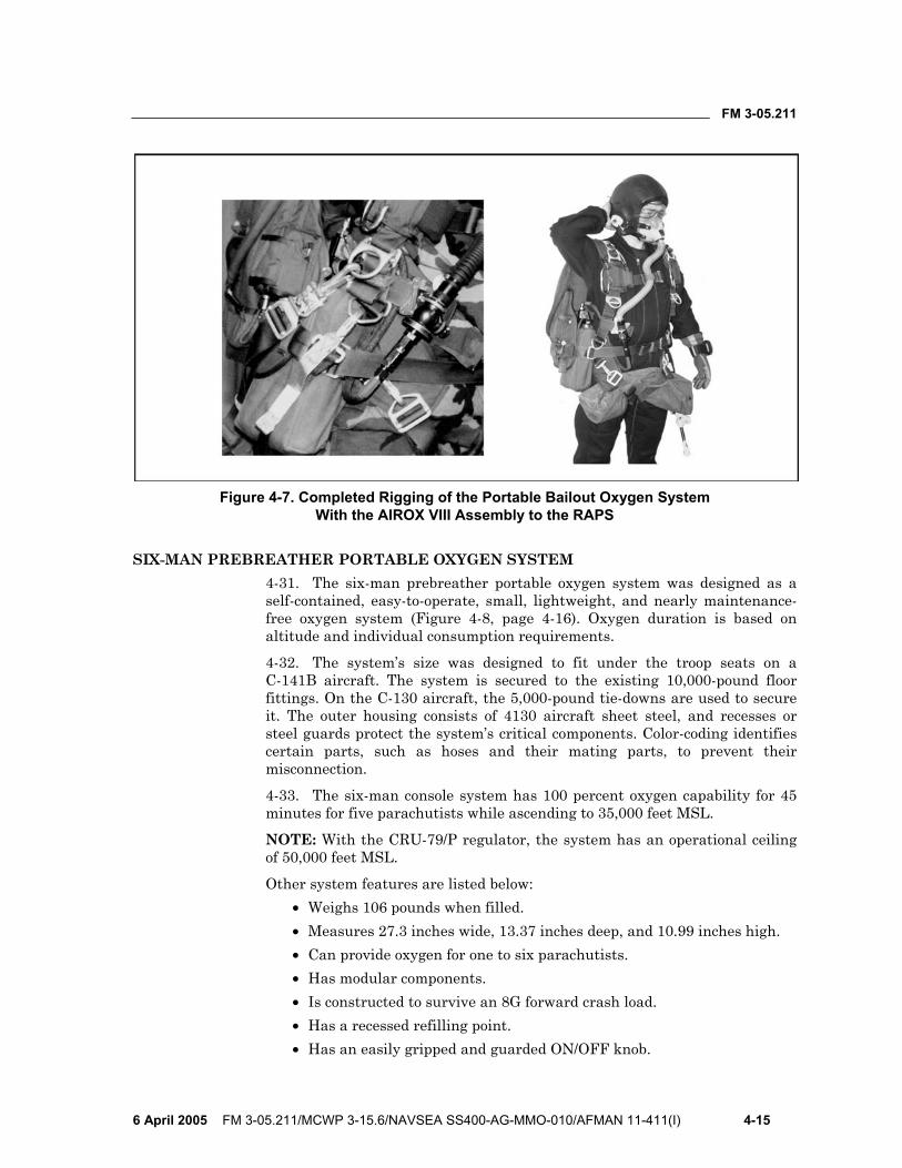
FM 3-05.211
6 April 2005 FM 3-05.211/MCWP 3-15.6/NAVSEA SS400-AG-MMO-010/AFMAN 11-411(I) 4-15
Figure 4-7. Completed Rigging of the Portable Bailout Oxygen System With the AIROX VIII Assembly to the RAPS
SIX-MAN PREBREATHER PORTABLE OXYGEN SYSTEM 4-31. The six-man prebreather portable oxygen system was designed as a self-contained, easy-to-operate, small, lightweight, and nearly maintenance-free oxygen system (Figure 4-8, page 4-16). Oxygen duration is based on altitude and individual consumption requirements.
4-32. The system’s size was designed to fit under the troop seats on a C-141B aircraft. The system is secured to the existing 10,000-pound floor fittings. On the C-130 aircraft, the 5,000-pound tie-downs are used to secure it. The outer housing consists of 4130 aircraft sheet steel, and recesses or steel guards protect the system’s critical components. Color-coding identifies certain parts, such as hoses and their mating parts, to prevent their misconnection.
4-33. The six-man console system has 100 percent oxygen capability for 45 minutes for five parachutists while ascending to 35,000 feet MSL.
NOTE: With the CRU-79/P regulator, the system has an operational ceiling of 50,000 feet MSL.
Other system features are listed below: • Weighs 106 pounds when filled. • Measures 27.3 inches wide, 13.37 inches deep, and 10.99 inches high. • Can provide oxygen for one to six parachutists. • Has modular components. • Is constructed to survive an 8G forward crash load. • Has a recessed refilling point. • Has an easily gripped and guarded ON/OFF knob.
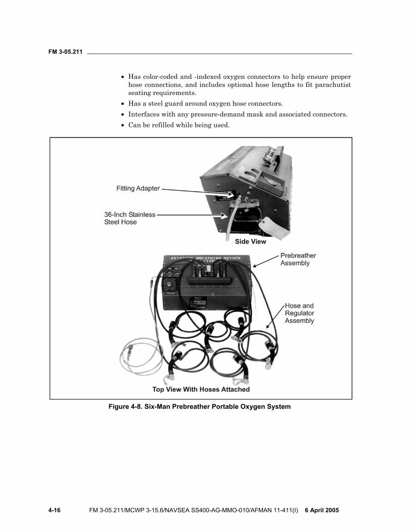
FM 3-05.211
4-16 FM 3-05.211/MCWP 3-15.6/NAVSEA SS400-AG-MMO-010/AFMAN 11-411(I) 6 April 2005
• Has color-coded and -indexed oxygen connectors to help ensure proper hose connections, and includes optional hose lengths to fit parachutist seating requirements.
• Has a steel guard around oxygen hose connectors. • Interfaces with any pressure-demand mask and associated connectors. • Can be refilled while being used.
Figure 4-8. Six-Man Prebreather Portable Oxygen System
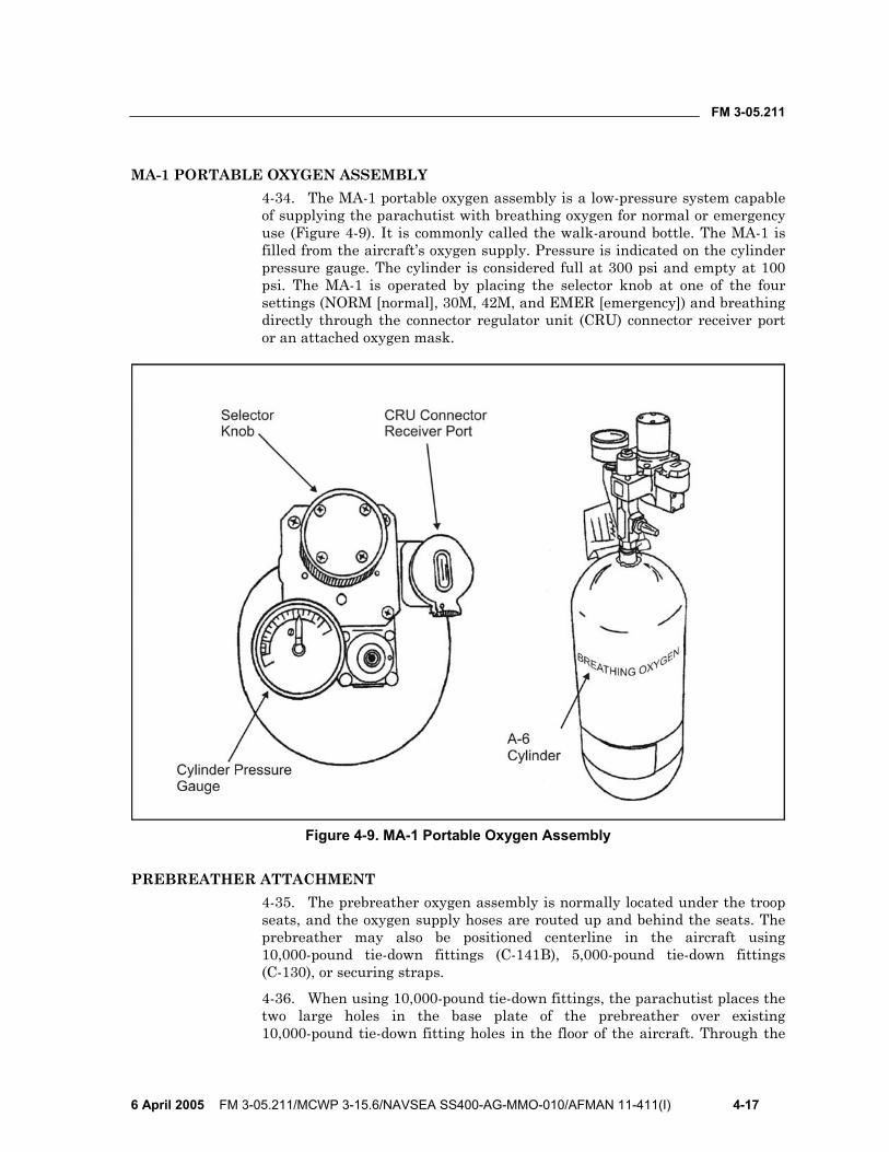
FM 3-05.211
6 April 2005 FM 3-05.211/MCWP 3-15.6/NAVSEA SS400-AG-MMO-010/AFMAN 11-411(I) 4-17
MA-1 PORTABLE OXYGEN ASSEMBLY 4-34. The MA-1 portable oxygen assembly is a low-pressure system capable of supplying the parachutist with breathing oxygen for normal or emergency use (Figure 4-9). It is commonly called the walk-around bottle. The MA-1 is filled from the aircraft’s oxygen supply. Pressure is indicated on the cylinder pressure gauge. The cylinder is considered full at 300 psi and empty at 100 psi. The MA-1 is operated by placing the selector knob at one of the four settings (NORM [normal], 30M, 42M, and EMER [emergency]) and breathing directly through the connector regulator unit (CRU) connector receiver port or an attached oxygen mask.
Figure 4-9. MA-1 Portable Oxygen Assembly
PREBREATHER ATTACHMENT 4-35. The prebreather oxygen assembly is normally located under the troop seats, and the oxygen supply hoses are routed up and behind the seats. The prebreather may also be positioned centerline in the aircraft using 10,000-pound tie-down fittings (C-141B), 5,000-pound tie-down fittings (C-130), or securing straps.
4-36. When using 10,000-pound tie-down fittings, the parachutist places the two large holes in the base plate of the prebreather over existing 10,000-pound tie-down fitting holes in the floor of the aircraft. Through the
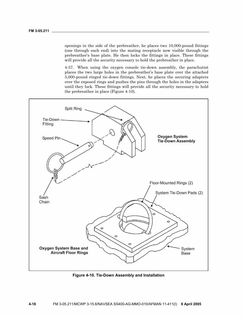
FM 3-05.211
4-18 FM 3-05.211/MCWP 3-15.6/NAVSEA SS400-AG-MMO-010/AFMAN 11-411(I) 6 April 2005
openings in the side of the prebreather, he places two 10,000-pound fittings (one through each end) into the mating receptacle now visible through the prebreather’s base plate. He then locks the fittings in place. These fittings will provide all the security necessary to hold the prebreather in place.
4-37. When using the oxygen console tie-down assembly, the parachutist places the two large holes in the prebreather’s base plate over the attached 5,000-pound ringed tie-down fittings. Next, he places the securing adapters over the exposed rings and pushes the pins through the holes in the adapters until they lock. These fittings will provide all the security necessary to hold the prebreather in place (Figure 4-10).
Figure 4-10. Tie-Down Assembly and Installation
FM 3-05.211
6 April 2005 FM 3-05.211/MCWP 3-15.6/NAVSEA SS400-AG-MMO-010/AFMAN 11-411(I) 4-19
4-38. Cargo straps are not necessary for added security when using the 10,000-pound tie-down fittings or oxygen console tie-down assembly. If cargo straps are used in place of the tie-down fittings, the parachutist places the straps through the securing access holes at each end of the prebreather and cinches tightly to existing fittings. NOTE: The prebreather carrying handles are not stressed for use as securing points.
THE “PRICE” CHECK 4-39. Each letter of the acronym PRICE represents an area of or a specific item of oxygen equipment that the parachutist must check. The PRICE check makes no provision for inspecting the mask or protective helmet. The parachutist checks—
• P - Pressure. He checks for full pressure on the particular system in use. • R - Regulator. He checks everything on the particular regulator in use.
He checks for dents, cracks, broken gauges, grease or oil, and movement of dials and levers. He checks the entire oxygen delivery system for leaks.
• I - Indicator. He checks to make sure the flow indicator shows that gas is flowing through the regulator from the storage system.
• C - Connections. He checks all hose connections. • E - Emergency equipment. He does a complete PRICE check on any
emergency oxygen equipment and the complete bailout system.
OXYGEN SAFETY PERSONNEL AND PREFLIGHT CHECKS 4-40. Oxygen safety personnel must be onboard each aircraft during MFF operations using supplemental oxygen. They must have received physio-logical training and unit-level technical training on the oxygen systems being used. For jumps from 18,000 feet or above, a USAF physiological technician will be requested with the aircraft and will be onboard for the jump. The oxygen safety personnel or the USAF physiological technician will—
• Plan for all oxygen equipment required for the mission. He will provide one additional mask of each size and one additional complete bailout system per six parachutists, and plan for one additional open oxygen station per every six parachutists in the event of a hose or regulator failure.
• Conduct preflight inspection and preflight operational checks of all oxygen equipment (Figures 4-11 and 4-12, pages 4-20 through 4-22).
• Supervise the transportation of and installation onboard the aircraft of prebreathers and oxygen cylinders.
• Issue oxygen supply hoses to each parachutist and supervise hose connection.
• Make sure the parachutists mask properly, fully open shutoff valves on the prebreathers, and receive oxygen after the aircraft procedure signal MASK is given.
• Periodically check oxygen pressure and equipment function during use (every 10 minutes).
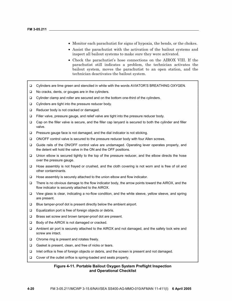
FM 3-05.211
4-20 FM 3-05.211/MCWP 3-15.6/NAVSEA SS400-AG-MMO-010/AFMAN 11-411(I) 6 April 2005
• Monitor each parachutist for signs of hypoxia, the bends, or the chokes. • Assist the parachutist with the activation of the bailout systems and
inspect all bailout systems to make sure they were activated. • Check the parachutist’s hose connections on the AIROX VIII. If the
parachutist still indicates a problem, the technician activates the bailout system, moves the parachutist to an open station, and the technician deactivates the bailout system.
Cylinders are lime green and stenciled in white with the words AVIATOR’S BREATHING OXYGEN.
No cracks, dents, or gouges are in the cylinders.
Cylinder clamp and roller are secured and on the bottom one-third of the cylinders.
Cylinders are tight into the pressure reducer body.
Reducer body is not cracked or damaged.
Filler valve, pressure gauge, and relief valve are tight into the pressure reducer body.
Cap on the filler valve is secure, and the filler cap lanyard is secured to both the cylinder and filler valve.
Pressure gauge face is not damaged, and the dial indicator is not sticking.
ON/OFF control valve is secured to the pressure reducer body with four Allen screws.
Guide rails of the ON/OFF control valve are undamaged. Operating lever operates properly, and the detent will hold the valve in the ON and the OFF positions.
Union elbow is secured tightly to the top of the pressure reducer, and the elbow directs the hose over the pressure gauge.
Hose assembly is not frayed or crushed, and the cloth covering is not worn and is free of oil and other contaminants.
Hose assembly is securely attached to the union elbow and flow indicator.
There is no obvious damage to the flow indicator body, the arrow points toward the AIROX, and the flow indicator is securely attached to the AIROX.
View glass is clear, indicating a no-flow condition, and the white sleeve, yellow sleeve, and spring are present.
Blue tamper-proof dot is present directly below the ambient airport.
Equalization port is free of foreign objects or debris.
Brass set screw and brown tamper-proof dot are present.
Body of the AIROX is not damaged or cracked.
Ambient air port is securely attached to the AIROX and not damaged, and the safety lock wire and screw are intact.
Chrome ring is present and rotates freely.
Gasket is present, clean, and free of nicks or tears.
Inlet orifice is free of foreign objects or debris, and the screen is present and not damaged.
Cover of the outlet orifice is spring-loaded and seats properly.
Figure 4-11. Portable Bailout Oxygen System Preflight Inspection and Operational Checklist
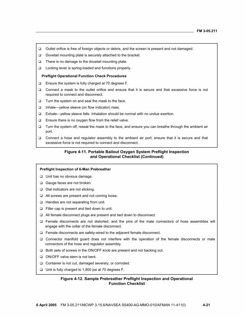
FM 3-05.211
6 April 2005 FM 3-05.211/MCWP 3-15.6/NAVSEA SS400-AG-MMO-010/AFMAN 11-411(I) 4-21
Outlet orifice is free of foreign objects or debris, and the screen is present and not damaged.
Dovetail mounting plate is securely attached to the bracket.
There is no damage to the dovetail mounting plate.
Locking lever is spring-loaded and functions properly.
Preflight Operational Function Check Procedures
Ensure the system is fully charged at 70 degrees F.
Connect a mask to the outlet orifice and ensure that it is secure and that excessive force is not required to connect and disconnect.
Turn the system on and seal the mask to the face.
Inhale—yellow sleeve (on flow indicator) rises.
Exhale—yellow sleeve falls. Inhalation should be normal with no undue exertion.
Ensure there is no oxygen flow from the relief valve.
Turn the system off, reseal the mask to the face, and ensure you can breathe through the ambient air port.
Connect a hose and regulator assembly to the ambient air port; ensure that it is secure and that excessive force is not required to connect and disconnect.
Figure 4-11. Portable Bailout Oxygen System Preflight Inspection and Operational Checklist (Continued)
Preflight Inspection of 6-Man Prebreather
Unit has no obvious damage.
Gauge faces are not broken.
Dial indicators are not sticking.
All screws are present and not coming loose.
Handles are not separating from unit.
Filler cap is present and tied down to unit.
All female disconnect plugs are present and tied down to disconnect.
Female disconnects are not distorted, and the pins of the male connectors of hose assemblies will engage with the collar of the female disconnect.
Female disconnects are safety-wired to the adjacent female disconnect.
Connector manifold guard does not interfere with the operation of the female disconnects or male connectors of the hose and regulator assembly.
Both sets of screws in the ON/OFF knob are present and not backing out.
ON/OFF valve stem is not bent.
Container is not cut, damaged severely, or corroded.
Unit is fully charged to 1,800 psi at 70 degrees F.
Figure 4-12. Sample Prebreather Preflight Inspection and Operational Function Checklist
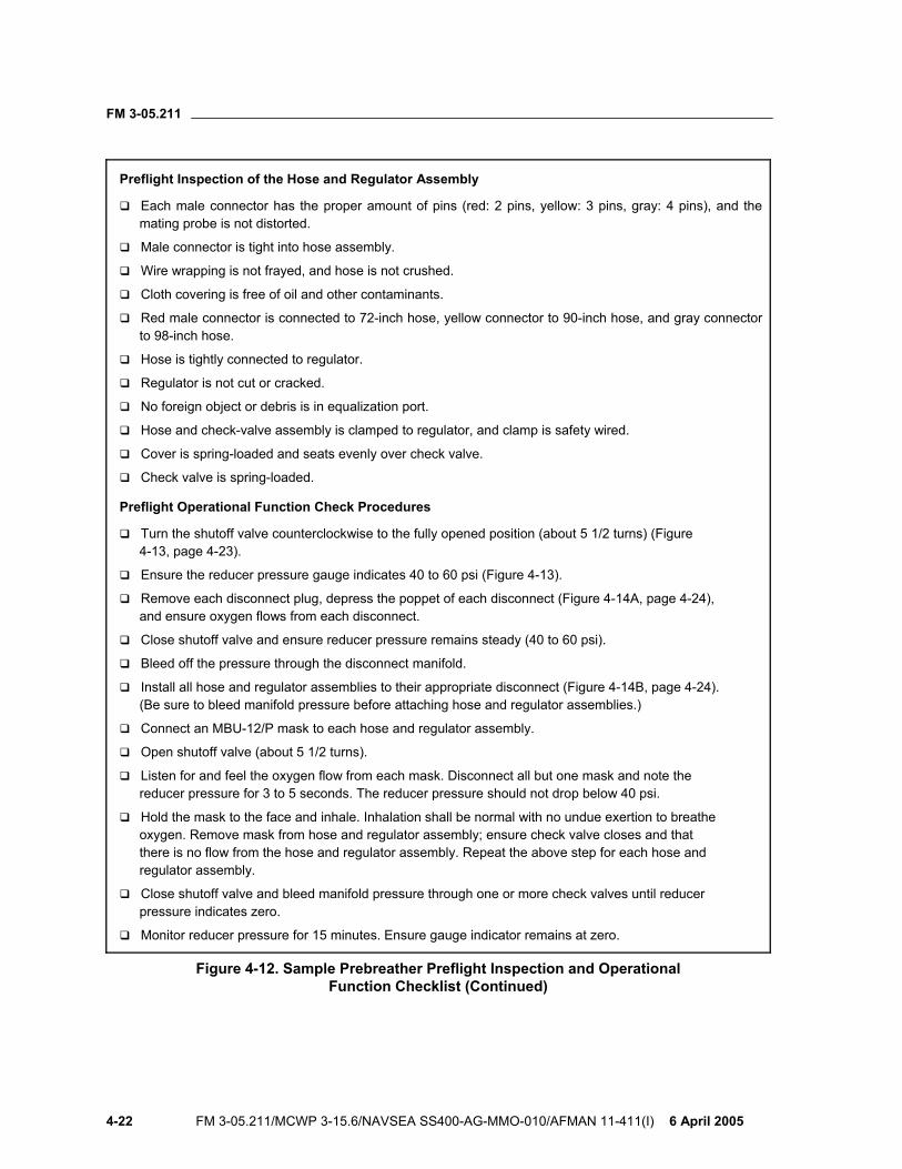
FM 3-05.211
4-22 FM 3-05.211/MCWP 3-15.6/NAVSEA SS400-AG-MMO-010/AFMAN 11-411(I) 6 April 2005
Preflight Inspection of the Hose and Regulator Assembly
Each male connector has the proper amount of pins (red: 2 pins, yellow: 3 pins, gray: 4 pins), and the mating probe is not distorted.
Male connector is tight into hose assembly.
Wire wrapping is not frayed, and hose is not crushed.
Cloth covering is free of oil and other contaminants.
Red male connector is connected to 72-inch hose, yellow connector to 90-inch hose, and gray connector to 98-inch hose.
Hose is tightly connected to regulator.
Regulator is not cut or cracked.
No foreign object or debris is in equalization port.
Hose and check-valve assembly is clamped to regulator, and clamp is safety wired.
Cover is spring-loaded and seats evenly over check valve.
Check valve is spring-loaded.
Preflight Operational Function Check Procedures
Turn the shutoff valve counterclockwise to the fully opened position (about 5 1/2 turns) (Figure 4-13, page 4-23).
Ensure the reducer pressure gauge indicates 40 to 60 psi (Figure 4-13).
Remove each disconnect plug, depress the poppet of each disconnect (Figure 4-14A, page 4-24), and ensure oxygen flows from each disconnect.
Close shutoff valve and ensure reducer pressure remains steady (40 to 60 psi).
Bleed off the pressure through the disconnect manifold.
Install all hose and regulator assemblies to their appropriate disconnect (Figure 4-14B, page 4-24). (Be sure to bleed manifold pressure before attaching hose and regulator assemblies.)
Connect an MBU-12/P mask to each hose and regulator assembly.
Open shutoff valve (about 5 1/2 turns).
Listen for and feel the oxygen flow from each mask. Disconnect all but one mask and note the reducer pressure for 3 to 5 seconds. The reducer pressure should not drop below 40 psi.
Hold the mask to the face and inhale. Inhalation shall be normal with no undue exertion to breathe oxygen. Remove mask from hose and regulator assembly; ensure check valve closes and that there is no flow from the hose and regulator assembly. Repeat the above step for each hose and regulator assembly.
Close shutoff valve and bleed manifold pressure through one or more check valves until reducer pressure indicates zero.
Monitor reducer pressure for 15 minutes. Ensure gauge indicator remains at zero.
Figure 4-12. Sample Prebreather Preflight Inspection and Operational Function Checklist (Continued)
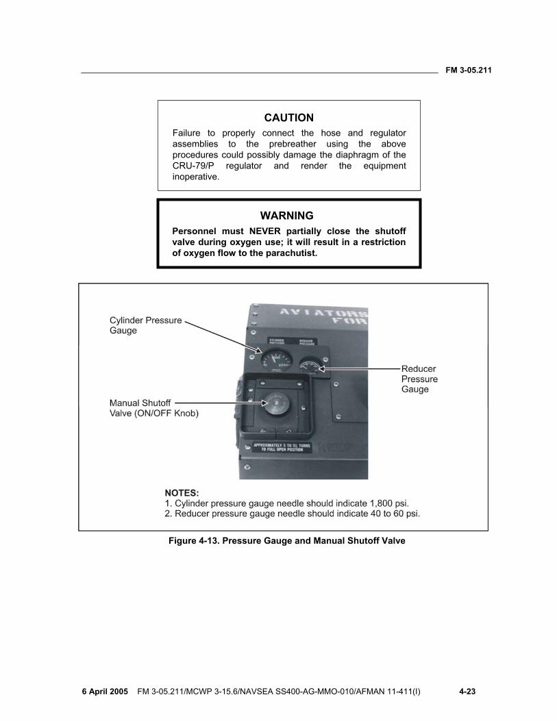
FM 3-05.211
6 April 2005 FM 3-05.211/MCWP 3-15.6/NAVSEA SS400-AG-MMO-010/AFMAN 11-411(I) 4-23
CAUTION
Failure to properly connect the hose and regulator assemblies to the prebreather using the above procedures could possibly damage the diaphragm of the CRU-79/P regulator and render the equipment inoperative.
WARNING Personnel must NEVER partially close the shutoff valve during oxygen use; it will result in a restriction of oxygen flow to the parachutist.
Figure 4-13. Pressure Gauge and Manual Shutoff Valve
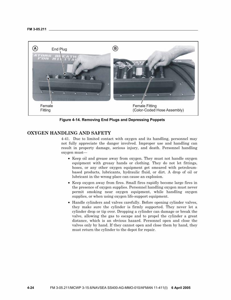
FM 3-05.211
4-24 FM 3-05.211/MCWP 3-15.6/NAVSEA SS400-AG-MMO-010/AFMAN 11-411(I) 6 April 2005
Figure 4-14. Removing End Plugs and Depressing Poppets
OXYGEN HANDLING AND SAFETY 4-41. Due to limited contact with oxygen and its handling, personnel may not fully appreciate the danger involved. Improper use and handling can result in property damage, serious injury, and death. Personnel handling oxygen must—
• Keep oil and grease away from oxygen. They must not handle oxygen equipment with greasy hands or clothing. They do not let fittings, hoses, or any other oxygen equipment get smeared with petroleum-based products, lubricants, hydraulic fluid, or dirt. A drop of oil or lubricant in the wrong place can cause an explosion.
• Keep oxygen away from fires. Small fires rapidly become large fires in the presence of oxygen supplies. Personnel handling oxygen must never permit smoking near oxygen equipment, while handling oxygen supplies, or when using oxygen life-support equipment.
• Handle cylinders and valves carefully. Before opening cylinder valves, they make sure the cylinder is firmly supported. They never let a cylinder drop or tip over. Dropping a cylinder can damage or break the valve, allowing the gas to escape and to propel the cylinder a great distance, which is an obvious hazard. Personnel open and close the valves only by hand. If they cannot open and close them by hand, they must return the cylinder to the depot for repair.
FM 3-05.211
6 April 2005 FM 3-05.211/MCWP 3-15.6/NAVSEA SS400-AG-MMO-010/AFMAN 11-411(I) 5-1
Chapter 5
Equipment and Weapon Rigging Procedures Free-fall parachutists will normally operate with individual equipment that includes clothing and equipment in keeping with the climatic conditions, food, and survival items. In addition, each parachutist will have a weapon, free-fall parachutist’s jump helmet, goggles, and altimeter. Free-fall parachutists jump and carry all detachment equipment and supplies as individual loads. If selected items must be dropped as accompanying supplies, they pack these supplies in appropriate aerial delivery containers.
EQUIPMENT AND WEAPON PACKING CONSIDERATIONS 5-1. The parachutist can attach or wear his individual equipment and weapon in several configurations (for example, exposed, placed in containers, or a mix of the two). Unit SOPs specify ways to pack equipment that are consistent with safety requirements. As a rule, units pack hard, bulky, or irregularly shaped (nonaerodynamic) items in containers. Parachutists can use rucksack rigging systems approved by their Service Test Board.
5-2. The parachutist packs his individual equipment in containers, kit bags, or the medium or large combat pack. He then attaches it to the equipment rings on the parachute’s main lift web. He may front or rear mount the combat pack using the improved equipment attaching sling or the H-harness (modified). He may attach both a front- and rear-mounted rucksack and equipment as long as he is under the 360-pound “all-up” total weight (to include personnel, gear, and weight of canopy suspended below the parachute). He should lower combat packs or any equipment that weighs more than 35 pounds.
5-3 The parachutist pads fragile items, such as weapon sights. He does not place crushable items, such as the protective mask, directly under the attaching harnesses. Exposed weapons or equipment, snap hooks, and projections are potential safety hazards that the parachutist tapes.
PARACHUTIST AND PARACHUTE LOAD LIMITATIONS 5-4 Commanders must not overload the parachutist with equipment. The variety and weight of equipment and weapons that can be attached to a parachutist (Tables 5-1 through 5-4, pages 5-2 and 5-3) may exceed the safe design limits of the MC-4 RAPS. Overloading can result in parachute damage, unsafe descent rates, and injury to the parachutist. Also, the parachutist’s actions and the time available to release the tie-down straps and to lower the equipment may interfere with his control of the parachute close to the ground.
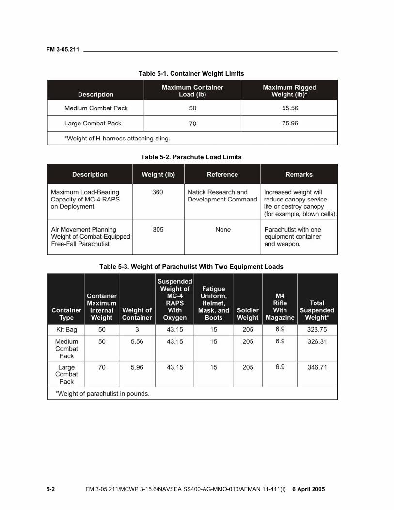
FM 3-05.211
5-2 FM 3-05.211/MCWP 3-15.6/NAVSEA SS400-AG-MMO-010/AFMAN 11-411(I) 6 April 2005
Table 5-1. Container Weight Limits
Table 5-2. Parachute Load Limits
Table 5-3. Weight of Parachutist With Two Equipment Loads
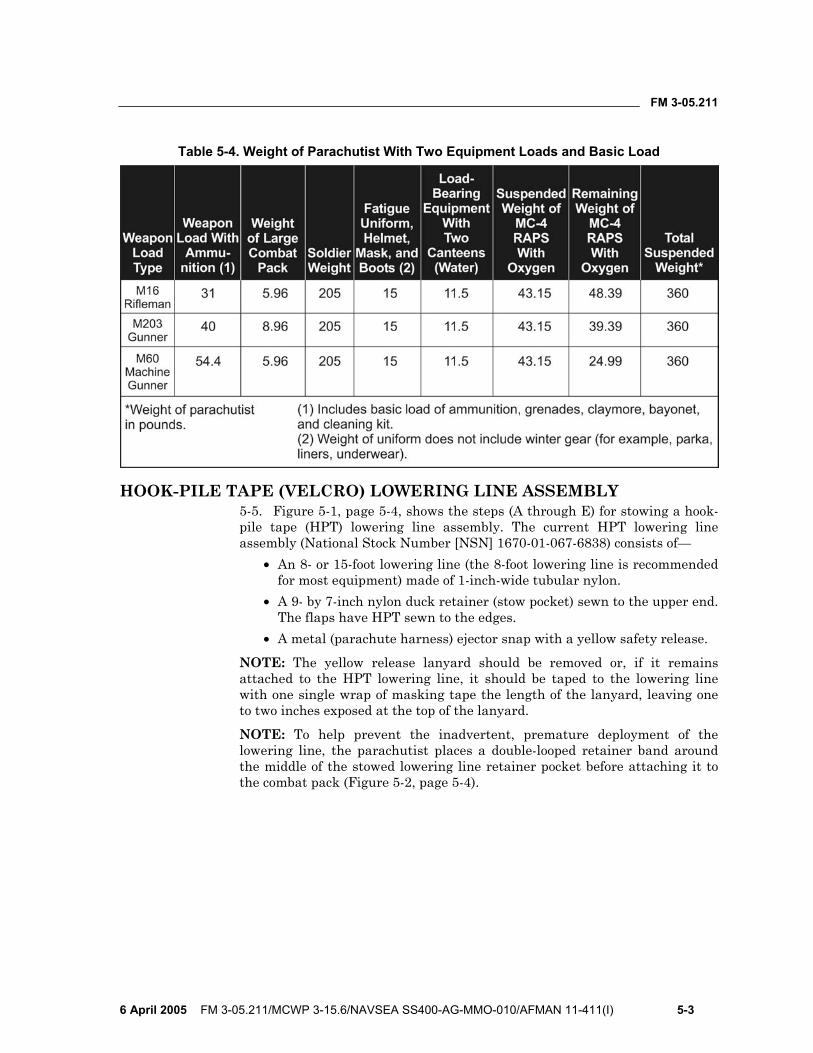
FM 3-05.211
6 April 2005 FM 3-05.211/MCWP 3-15.6/NAVSEA SS400-AG-MMO-010/AFMAN 11-411(I) 5-3
Table 5-4. Weight of Parachutist With Two Equipment Loads and Basic Load
HOOK-PILE TAPE (VELCRO) LOWERING LINE ASSEMBLY 5-5. Figure 5-1, page 5-4, shows the steps (A through E) for stowing a hook-pile tape (HPT) lowering line assembly. The current HPT lowering line assembly (National Stock Number [NSN] 1670-01-067-6838) consists of—
• An 8- or 15-foot lowering line (the 8-foot lowering line is recommended for most equipment) made of 1-inch-wide tubular nylon.
• A 9- by 7-inch nylon duck retainer (stow pocket) sewn to the upper end. The flaps have HPT sewn to the edges.
• A metal (parachute harness) ejector snap with a yellow safety release.
NOTE: The yellow release lanyard should be removed or, if it remains attached to the HPT lowering line, it should be taped to the lowering line with one single wrap of masking tape the length of the lanyard, leaving one to two inches exposed at the top of the lanyard.
NOTE: To help prevent the inadvertent, premature deployment of the lowering line, the parachutist places a double-looped retainer band around the middle of the stowed lowering line retainer pocket before attaching it to the combat pack (Figure 5-2, page 5-4).
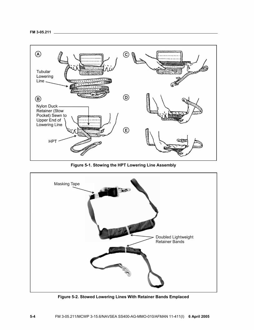
FM 3-05.211
5-4 FM 3-05.211/MCWP 3-15.6/NAVSEA SS400-AG-MMO-010/AFMAN 11-411(I) 6 April 2005
Figure 5-1. Stowing the HPT Lowering Line Assembly
Figure 5-2. Stowed Lowering Lines With Retainer Bands Emplaced
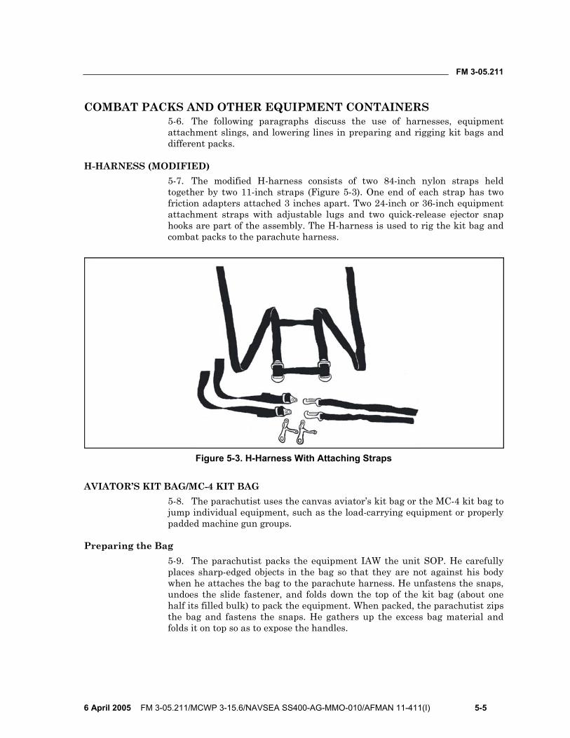
FM 3-05.211
6 April 2005 FM 3-05.211/MCWP 3-15.6/NAVSEA SS400-AG-MMO-010/AFMAN 11-411(I) 5-5
COMBAT PACKS AND OTHER EQUIPMENT CONTAINERS 5-6. The following paragraphs discuss the use of harnesses, equipment attachment slings, and lowering lines in preparing and rigging kit bags and different packs.
H-HARNESS (MODIFIED) 5-7. The modified H-harness consists of two 84-inch nylon straps held together by two 11-inch straps (Figure 5-3). One end of each strap has two friction adapters attached 3 inches apart. Two 24-inch or 36-inch equipment attachment straps with adjustable lugs and two quick-release ejector snap hooks are part of the assembly. The H-harness is used to rig the kit bag and combat packs to the parachute harness.
Figure 5-3. H-Harness With Attaching Straps
AVIATOR’S KIT BAG/MC-4 KIT BAG 5-8. The parachutist uses the canvas aviator’s kit bag or the MC-4 kit bag to jump individual equipment, such as the load-carrying equipment or properly padded machine gun groups.
Preparing the Bag 5-9. The parachutist packs the equipment IAW the unit SOP. He carefully places sharp-edged objects in the bag so that they are not against his body when he attaches the bag to the parachute harness. He unfastens the snaps, undoes the slide fastener, and folds down the top of the kit bag (about one half its filled bulk) to pack the equipment. When packed, the parachutist zips the bag and fastens the snaps. He gathers up the excess bag material and folds it on top so as to expose the handles.
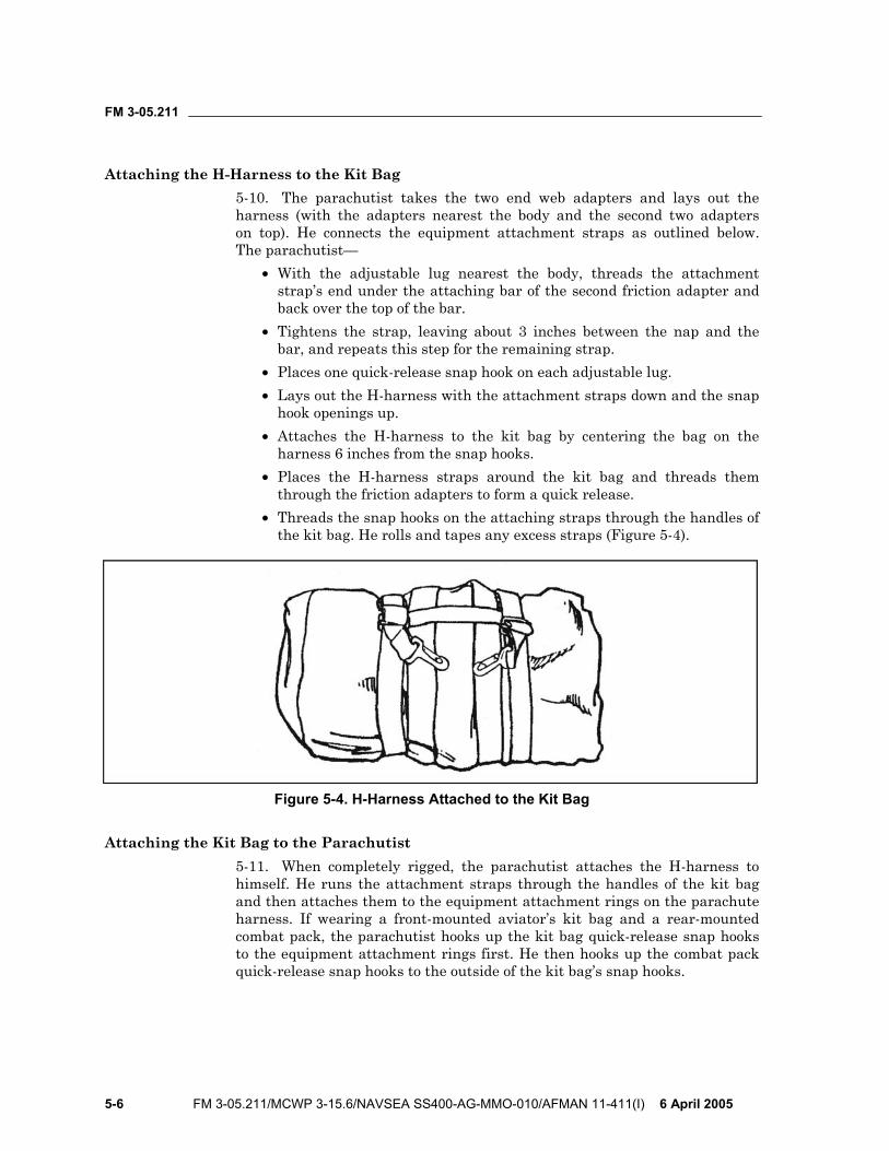
FM 3-05.211
5-6 FM 3-05.211/MCWP 3-15.6/NAVSEA SS400-AG-MMO-010/AFMAN 11-411(I) 6 April 2005
Attaching the H-Harness to the Kit Bag 5-10. The parachutist takes the two end web adapters and lays out the harness (with the adapters nearest the body and the second two adapters on top). He connects the equipment attachment straps as outlined below. The parachutist—
• With the adjustable lug nearest the body, threads the attachment strap’s end under the attaching bar of the second friction adapter and back over the top of the bar.
• Tightens the strap, leaving about 3 inches between the nap and the bar, and repeats this step for the remaining strap.
• Places one quick-release snap hook on each adjustable lug. • Lays out the H-harness with the attachment straps down and the snap
hook openings up. • Attaches the H-harness to the kit bag by centering the bag on the
harness 6 inches from the snap hooks. • Places the H-harness straps around the kit bag and threads them
through the friction adapters to form a quick release. • Threads the snap hooks on the attaching straps through the handles of
the kit bag. He rolls and tapes any excess straps (Figure 5-4).
Figure 5-4. H-Harness Attached to the Kit Bag
Attaching the Kit Bag to the Parachutist 5-11. When completely rigged, the parachutist attaches the H-harness to himself. He runs the attachment straps through the handles of the kit bag and then attaches them to the equipment attachment rings on the parachute harness. If wearing a front-mounted aviator’s kit bag and a rear-mounted combat pack, the parachutist hooks up the kit bag quick-release snap hooks to the equipment attachment rings first. He then hooks up the combat pack quick-release snap hooks to the outside of the kit bag’s snap hooks.
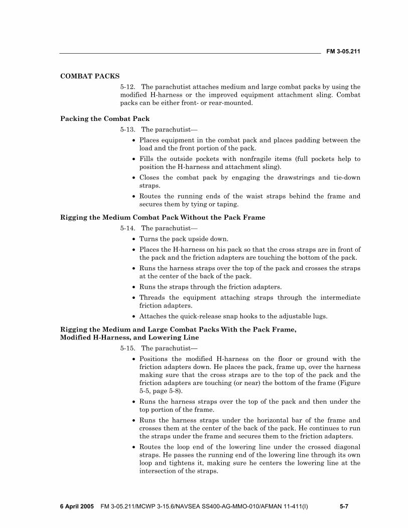
FM 3-05.211
6 April 2005 FM 3-05.211/MCWP 3-15.6/NAVSEA SS400-AG-MMO-010/AFMAN 11-411(I) 5-7
COMBAT PACKS 5-12. The parachutist attaches medium and large combat packs by using the modified H-harness or the improved equipment attachment sling. Combat packs can be either front- or rear-mounted.
Packing the Combat Pack 5-13. The parachutist—
• Places equipment in the combat pack and places padding between the load and the front portion of the pack.
• Fills the outside pockets with nonfragile items (full pockets help to position the H-harness and attachment sling).
• Closes the combat pack by engaging the drawstrings and tie-down straps.
• Routes the running ends of the waist straps behind the frame and secures them by tying or taping.
Rigging the Medium Combat Pack Without the Pack Frame 5-14. The parachutist—
• Turns the pack upside down. • Places the H-harness on his pack so that the cross straps are in front of
the pack and the friction adapters are touching the bottom of the pack. • Runs the harness straps over the top of the pack and crosses the straps
at the center of the back of the pack. • Runs the straps through the friction adapters. • Threads the equipment attaching straps through the intermediate
friction adapters. • Attaches the quick-release snap hooks to the adjustable lugs.
Rigging the Medium and Large Combat Packs With the Pack Frame, Modified H-Harness, and Lowering Line
5-15. The parachutist— • Positions the modified H-harness on the floor or ground with the
friction adapters down. He places the pack, frame up, over the harness making sure that the cross straps are to the top of the pack and the friction adapters are touching (or near) the bottom of the frame (Figure 5-5, page 5-8).
• Runs the harness straps over the top of the pack and then under the top portion of the frame.
• Runs the harness straps under the horizontal bar of the frame and crosses them at the center of the back of the pack. He continues to run the straps under the frame and secures them to the friction adapters.
• Routes the loop end of the lowering line under the crossed diagonal straps. He passes the running end of the lowering line through its own loop and tightens it, making sure he centers the lowering line at the intersection of the straps.
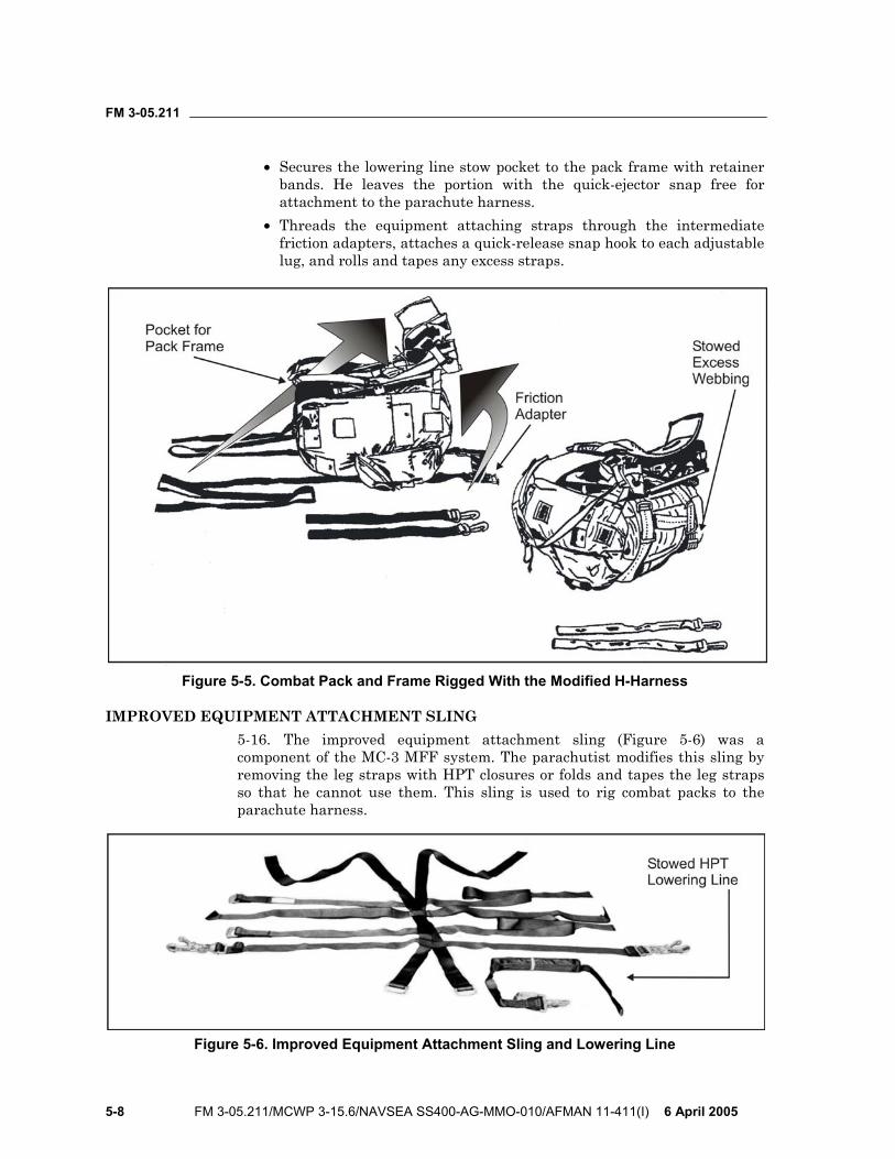
FM 3-05.211
5-8 FM 3-05.211/MCWP 3-15.6/NAVSEA SS400-AG-MMO-010/AFMAN 11-411(I) 6 April 2005
• Secures the lowering line stow pocket to the pack frame with retainer bands. He leaves the portion with the quick-ejector snap free for attachment to the parachute harness.
• Threads the equipment attaching straps through the intermediate friction adapters, attaches a quick-release snap hook to each adjustable lug, and rolls and tapes any excess straps.
Figure 5-5. Combat Pack and Frame Rigged With the Modified H-Harness
IMPROVED EQUIPMENT ATTACHMENT SLING 5-16. The improved equipment attachment sling (Figure 5-6) was a component of the MC-3 MFF system. The parachutist modifies this sling by removing the leg straps with HPT closures or folds and tapes the leg straps so that he cannot use them. This sling is used to rig combat packs to the parachute harness.
Figure 5-6. Improved Equipment Attachment Sling and Lowering Line
FM 3-05.211
6 April 2005 FM 3-05.211/MCWP 3-15.6/NAVSEA SS400-AG-MMO-010/AFMAN 11-411(I) 5-9
Rigging the Large Combat Pack With the Improved Equipment Attachment Sling (Spider Harness) and Lowering Line
5-17. The parachutist— • Tightens and secures all straps on the pack and positions the pack with
the frame up (Figure 5-7A, page 5-10). • Positions the harness on the frame with the friction adapters on the
diagonal locking straps at the bottom of the frame and the running ends at the top of the frame.
• Routes the diagonal locking strap friction adapters under the pack frame’s base.
• Routes the anchor straps (parachute harness attaching straps with adjustable quick-release lugs) and lateral locking straps under the shoulder straps and over the pack frame.
• Turns the pack over and routes the running ends of the diagonal locking straps around the long axis of the pack, across the straps at the center of the back.
• Secures the diagonal locking straps to the respective friction adapters that protrude beneath the bottom of the pack frame (Figure 5-7B).
• Tightens the lateral locking straps and secures them around the pack and to their respective friction adapters (Figure 5-7C).
NOTE: If the pack is small, the parachutist crosses and tightens the lateral locking straps and secures them around the pack and to their opposite friction adapters. • Folds and secures the running ends of all straps to themselves with
tape or ties them with 1/4-inch cotton webbing. • Places the combat pack in an upright position. • Attaches a quick-release snap hook to each adjustable lug so that the
latch handles face away from his body when he attaches the combat pack to the equipment rings (Figure 5-7D).
WARNING The parachutist tapes all combat pack shoulder strap quick-ejector releases to preclude inadvertent release in free fall, causing instability.
Attaching the Lowering Line 5-18. The parachutist—
• Routes the loop end of the lowering line under the crossed diagonal straps between the diagonal straps and the loop on the backside of the diagonal straps.
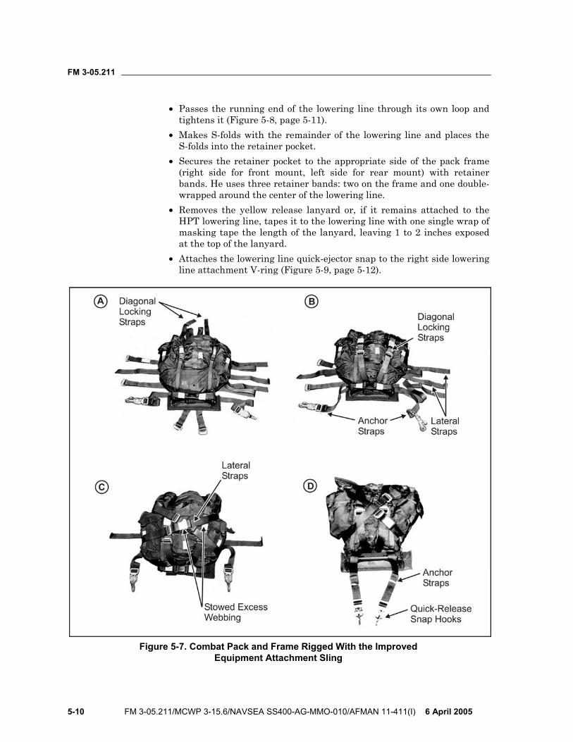
FM 3-05.211
5-10 FM 3-05.211/MCWP 3-15.6/NAVSEA SS400-AG-MMO-010/AFMAN 11-411(I) 6 April 2005
• Passes the running end of the lowering line through its own loop and tightens it (Figure 5-8, page 5-11).
• Makes S-folds with the remainder of the lowering line and places the S-folds into the retainer pocket.
• Secures the retainer pocket to the appropriate side of the pack frame (right side for front mount, left side for rear mount) with retainer bands. He uses three retainer bands: two on the frame and one double-wrapped around the center of the lowering line.
• Removes the yellow release lanyard or, if it remains attached to the HPT lowering line, tapes it to the lowering line with one single wrap of masking tape the length of the lanyard, leaving 1 to 2 inches exposed at the top of the lanyard.
• Attaches the lowering line quick-ejector snap to the right side lowering line attachment V-ring (Figure 5-9, page 5-12).
Figure 5-7. Combat Pack and Frame Rigged With the Improved Equipment Attachment Sling
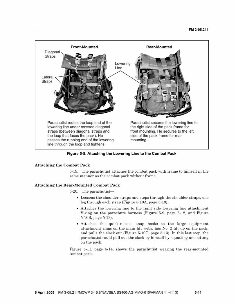
FM 3-05.211
6 April 2005 FM 3-05.211/MCWP 3-15.6/NAVSEA SS400-AG-MMO-010/AFMAN 11-411(I) 5-11
Figure 5-8. Attaching the Lowering Line to the Combat Pack
Attaching the Combat Pack 5-19. The parachutist attaches the combat pack with frame to himself in the same manner as the combat pack without frame.
Attaching the Rear-Mounted Combat Pack 5-20. The parachutist—
• Loosens the shoulder straps and steps through the shoulder straps, one leg through each strap (Figure 5-10A, page 5-13).
• Attaches the lowering line to the right side lowering line attachment V-ring on the parachute harness (Figure 5-9, page 5-12, and Figure 5-10B, page 5-13).
• Attaches the quick-release snap hooks to the large equipment attachment rings on the main lift webs, has No. 2 lift up on the pack, and pulls the slack out (Figure 5-10C, page 5-13). In this last step, the parachutist could pull out the slack by himself by squatting and sitting on the pack.
Figure 5-11, page 5-14, shows the parachutist wearing the rear-mounted combat pack.
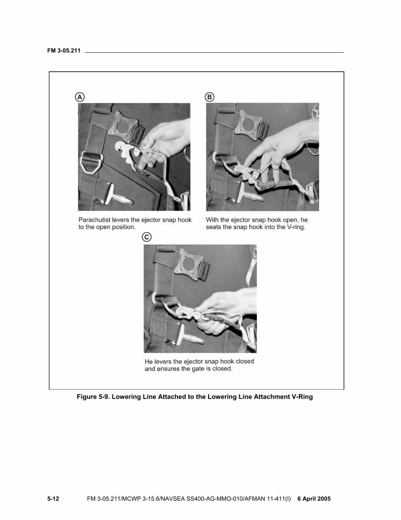
FM 3-05.211
5-12 FM 3-05.211/MCWP 3-15.6/NAVSEA SS400-AG-MMO-010/AFMAN 11-411(I) 6 April 2005
Figure 5-9. Lowering Line Attached to the Lowering Line Attachment V-Ring
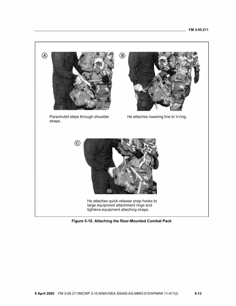
FM 3-05.211
6 April 2005 FM 3-05.211/MCWP 3-15.6/NAVSEA SS400-AG-MMO-010/AFMAN 11-411(I) 5-13
Figure 5-10. Attaching the Rear-Mounted Combat Pack
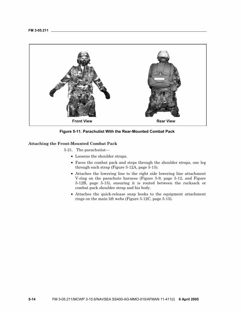
FM 3-05.211
5-14 FM 3-05.211/MCWP 3-15.6/NAVSEA SS400-AG-MMO-010/AFMAN 11-411(I) 6 April 2005
Figure 5-11. Parachutist With the Rear-Mounted Combat Pack
Attaching the Front-Mounted Combat Pack 5-21. The parachutist—
• Loosens the shoulder straps. • Faces the combat pack and steps through the shoulder straps, one leg
through each strap (Figure 5-12A, page 5-15). • Attaches the lowering line to the right side lowering line attachment
V-ring on the parachute harness (Figure 5-9, page 5-12, and Figure 5-12B, page 5-15), ensuring it is routed between the rucksack or combat pack shoulder strap and his body.
• Attaches the quick-release snap hooks to the equipment attachment rings on the main lift webs (Figure 5-12C, page 5-15).
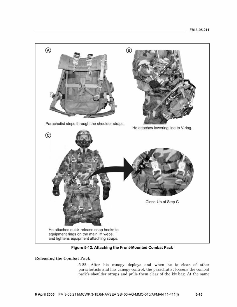
FM 3-05.211
6 April 2005 FM 3-05.211/MCWP 3-15.6/NAVSEA SS400-AG-MMO-010/AFMAN 11-411(I) 5-15
Figure 5-12. Attaching the Front-Mounted Combat Pack
Releasing the Combat Pack 5-22. After his canopy deploys and when he is clear of other parachutists and has canopy control, the parachutist loosens the combat pack’s shoulder straps and pulls them clear of the kit bag. At the same
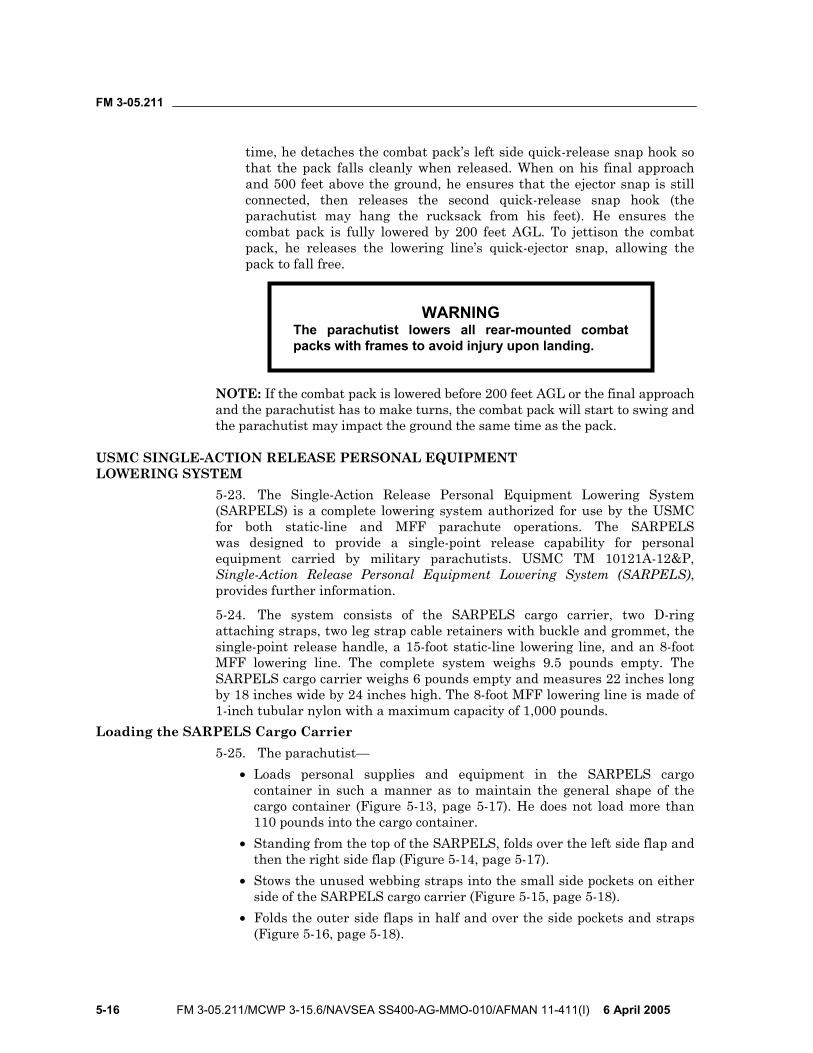
FM 3-05.211
5-16 FM 3-05.211/MCWP 3-15.6/NAVSEA SS400-AG-MMO-010/AFMAN 11-411(I) 6 April 2005
time, he detaches the combat pack’s left side quick-release snap hook so that the pack falls cleanly when released. When on his final approach and 500 feet above the ground, he ensures that the ejector snap is still connected, then releases the second quick-release snap hook (the parachutist may hang the rucksack from his feet). He ensures the combat pack is fully lowered by 200 feet AGL. To jettison the combat pack, he releases the lowering line’s quick-ejector snap, allowing the pack to fall free.
WARNING The parachutist lowers all rear-mounted combat packs with frames to avoid injury upon landing.
NOTE: If the combat pack is lowered before 200 feet AGL or the final approach and the parachutist has to make turns, the combat pack will start to swing and the parachutist may impact the ground the same time as the pack.
USMC SINGLE-ACTION RELEASE PERSONAL EQUIPMENT LOWERING SYSTEM
5-23. The Single-Action Release Personal Equipment Lowering System (SARPELS) is a complete lowering system authorized for use by the USMC for both static-line and MFF parachute operations. The SARPELS was designed to provide a single-point release capability for personal equipment carried by military parachutists. USMC TM 10121A-12&P, Single-Action Release Personal Equipment Lowering System (SARPELS), provides further information.
5-24. The system consists of the SARPELS cargo carrier, two D-ring attaching straps, two leg strap cable retainers with buckle and grommet, the single-point release handle, a 15-foot static-line lowering line, and an 8-foot MFF lowering line. The complete system weighs 9.5 pounds empty. The SARPELS cargo carrier weighs 6 pounds empty and measures 22 inches long by 18 inches wide by 24 inches high. The 8-foot MFF lowering line is made of 1-inch tubular nylon with a maximum capacity of 1,000 pounds.
Loading the SARPELS Cargo Carrier 5-25. The parachutist—
• Loads personal supplies and equipment in the SARPELS cargo container in such a manner as to maintain the general shape of the cargo container (Figure 5-13, page 5-17). He does not load more than 110 pounds into the cargo container.
• Standing from the top of the SARPELS, folds over the left side flap and then the right side flap (Figure 5-14, page 5-17).
• Stows the unused webbing straps into the small side pockets on either side of the SARPELS cargo carrier (Figure 5-15, page 5-18).
• Folds the outer side flaps in half and over the side pockets and straps (Figure 5-16, page 5-18).
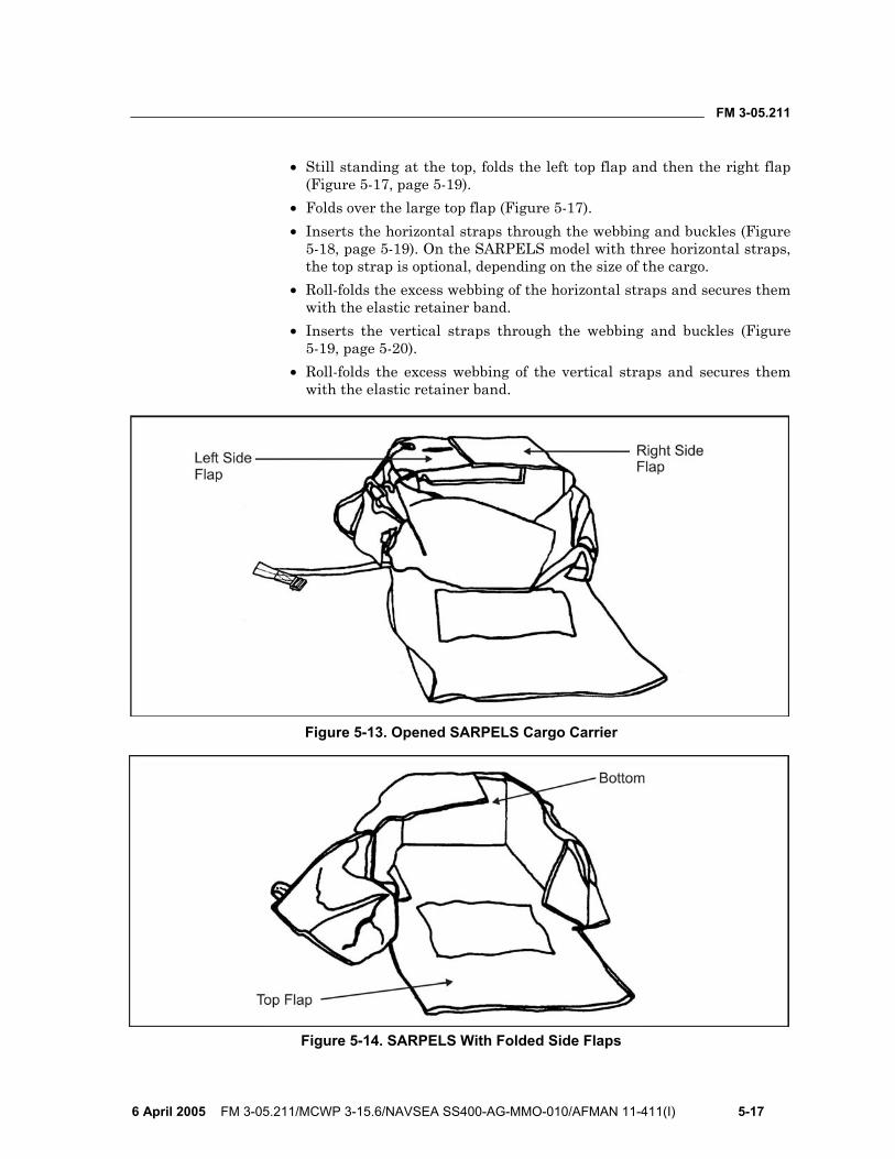
FM 3-05.211
6 April 2005 FM 3-05.211/MCWP 3-15.6/NAVSEA SS400-AG-MMO-010/AFMAN 11-411(I) 5-17
• Still standing at the top, folds the left top flap and then the right flap (Figure 5-17, page 5-19).
• Folds over the large top flap (Figure 5-17). • Inserts the horizontal straps through the webbing and buckles (Figure
5-18, page 5-19). On the SARPELS model with three horizontal straps, the top strap is optional, depending on the size of the cargo.
• Roll-folds the excess webbing of the horizontal straps and secures them with the elastic retainer band.
• Inserts the vertical straps through the webbing and buckles (Figure 5-19, page 5-20).
• Roll-folds the excess webbing of the vertical straps and secures them with the elastic retainer band.
Figure 5-13. Opened SARPELS Cargo Carrier
Figure 5-14. SARPELS With Folded Side Flaps
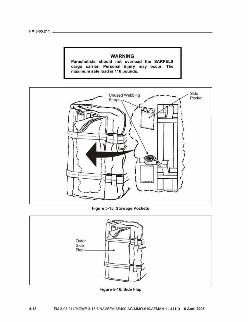
FM 3-05.211
5-18 FM 3-05.211/MCWP 3-15.6/NAVSEA SS400-AG-MMO-010/AFMAN 11-411(I) 6 April 2005
WARNING Parachutists should not overload the SARPELS cargo carrier. Personal injury may occur. The maximum safe load is 110 pounds.
Figure 5-15. Stowage Pockets
Figure 5-16. Side Flap
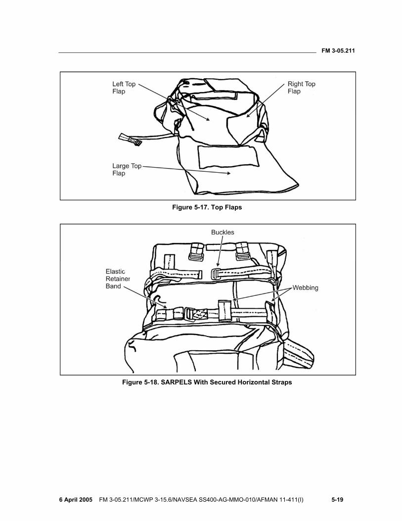
FM 3-05.211
6 April 2005 FM 3-05.211/MCWP 3-15.6/NAVSEA SS400-AG-MMO-010/AFMAN 11-411(I) 5-19
Figure 5-17. Top Flaps
Figure 5-18. SARPELS With Secured Horizontal Straps
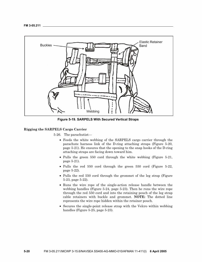
FM 3-05.211
5-20 FM 3-05.211/MCWP 3-15.6/NAVSEA SS400-AG-MMO-010/AFMAN 11-411(I) 6 April 2005
Figure 5-19. SARPELS With Secured Vertical Straps
Rigging the SARPELS Cargo Carrier 5-26. The parachutist—
• Feeds the white webbing of the SARPELS cargo carrier through the parachute harness link of the D-ring attaching straps (Figure 5-20, page 5-21). He ensures that the opening to the snap hooks of the D-ring attaching straps are facing down toward him.
• Pulls the green 550 cord through the white webbing (Figure 5-21, page 5-21).
• Pulls the red 550 cord through the green 550 cord (Figure 5-22, page 5-22).
• Pulls the red 550 cord through the grommet of the leg strap (Figure 5-23, page 5-22).
• Runs the wire rope of the single-action release handle between the webbing handles (Figure 5-24, page 5-23). Then he runs the wire rope through the red 550 cord and into the retaining pouch of the leg strap cable retainers with buckle and grommet. NOTE: The dotted line represents the wire rope hidden within the retainer pouch.
• Secures the single-point release strap with the Velcro within webbing handles (Figure 5-25, page 5-23).
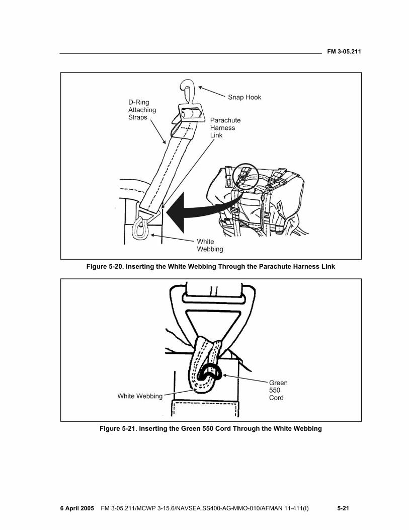
FM 3-05.211
6 April 2005 FM 3-05.211/MCWP 3-15.6/NAVSEA SS400-AG-MMO-010/AFMAN 11-411(I) 5-21
Figure 5-20. Inserting the White Webbing Through the Parachute Harness Link
Figure 5-21. Inserting the Green 550 Cord Through the White Webbing
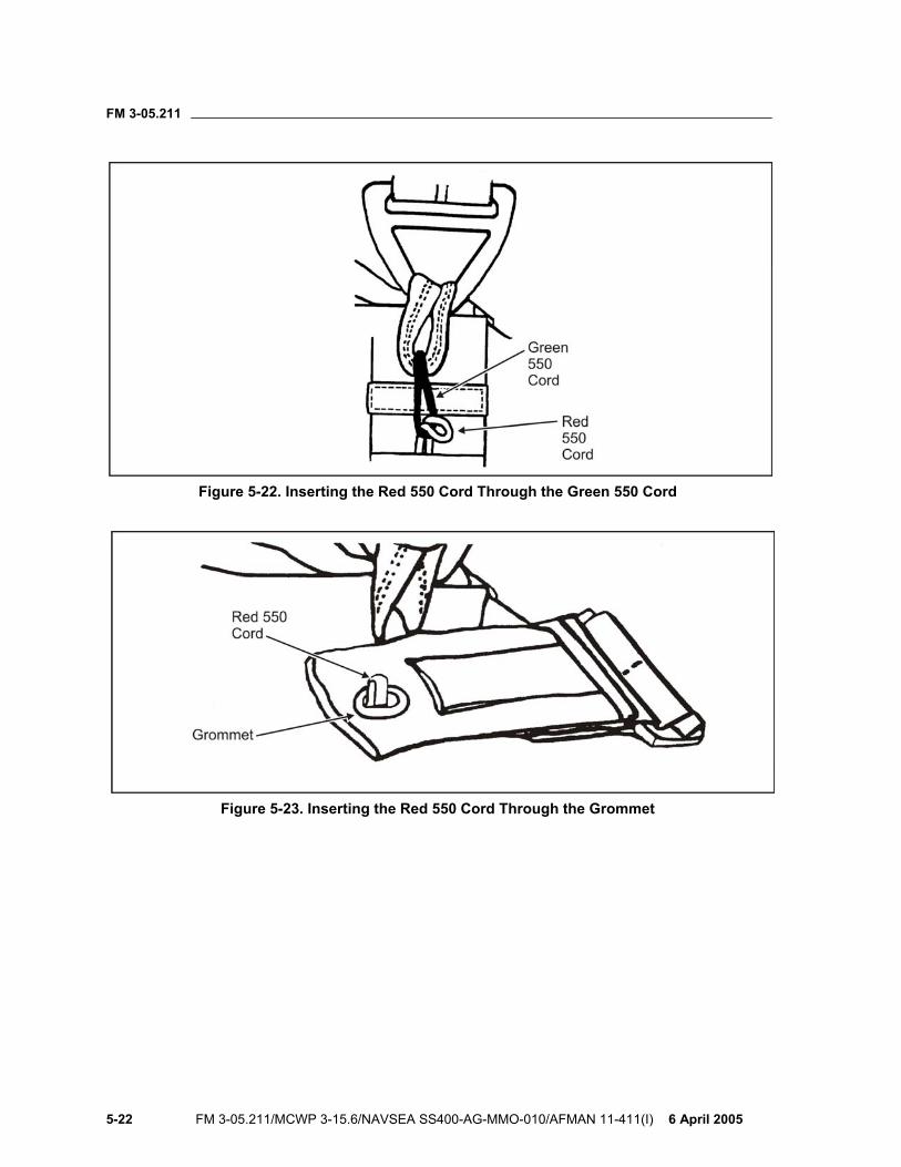
FM 3-05.211
5-22 FM 3-05.211/MCWP 3-15.6/NAVSEA SS400-AG-MMO-010/AFMAN 11-411(I) 6 April 2005
Figure 5-22. Inserting the Red 550 Cord Through the Green 550 Cord
Figure 5-23. Inserting the Red 550 Cord Through the Grommet
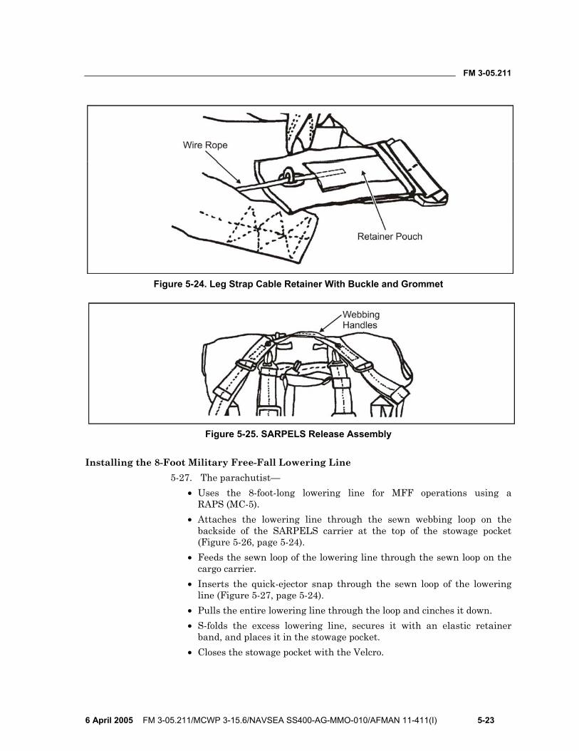
FM 3-05.211
6 April 2005 FM 3-05.211/MCWP 3-15.6/NAVSEA SS400-AG-MMO-010/AFMAN 11-411(I) 5-23
Figure 5-24. Leg Strap Cable Retainer With Buckle and Grommet
Figure 5-25. SARPELS Release Assembly
Installing the 8-Foot Military Free-Fall Lowering Line 5-27. The parachutist—
• Uses the 8-foot-long lowering line for MFF operations using a RAPS (MC-5).
• Attaches the lowering line through the sewn webbing loop on the backside of the SARPELS carrier at the top of the stowage pocket (Figure 5-26, page 5-24).
• Feeds the sewn loop of the lowering line through the sewn loop on the cargo carrier.
• Inserts the quick-ejector snap through the sewn loop of the lowering line (Figure 5-27, page 5-24).
• Pulls the entire lowering line through the loop and cinches it down. • S-folds the excess lowering line, secures it with an elastic retainer
band, and places it in the stowage pocket. • Closes the stowage pocket with the Velcro.
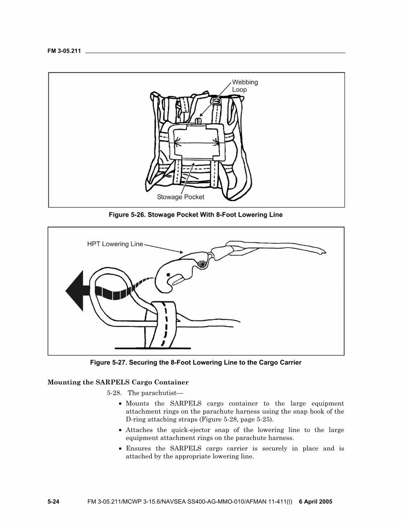
FM 3-05.211
5-24 FM 3-05.211/MCWP 3-15.6/NAVSEA SS400-AG-MMO-010/AFMAN 11-411(I) 6 April 2005
Figure 5-26. Stowage Pocket With 8-Foot Lowering Line
Figure 5-27. Securing the 8-Foot Lowering Line to the Cargo Carrier
Mounting the SARPELS Cargo Container 5-28. The parachutist—
• Mounts the SARPELS cargo container to the large equipment attachment rings on the parachute harness using the snap hook of the D-ring attaching straps (Figure 5-28, page 5-25).
• Attaches the quick-ejector snap of the lowering line to the large equipment attachment rings on the parachute harness.
• Ensures the SARPELS cargo carrier is securely in place and is attached by the appropriate lowering line.
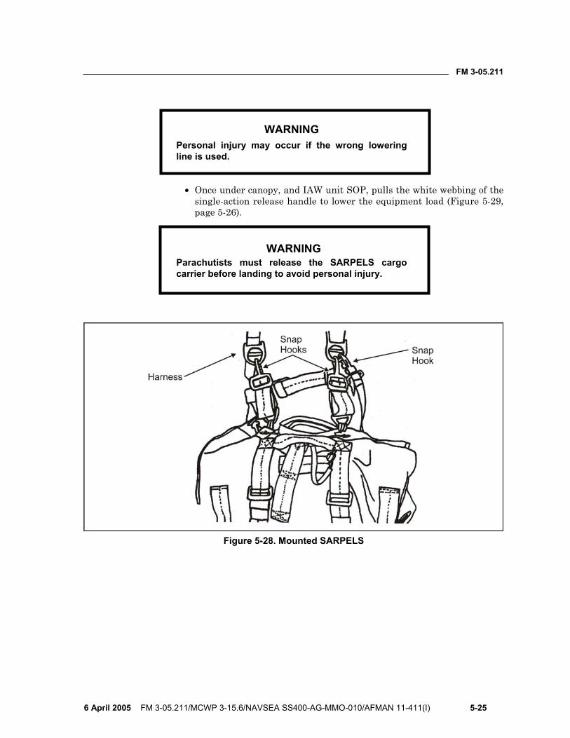
FM 3-05.211
6 April 2005 FM 3-05.211/MCWP 3-15.6/NAVSEA SS400-AG-MMO-010/AFMAN 11-411(I) 5-25
WARNING Personal injury may occur if the wrong lowering line is used.
• Once under canopy, and IAW unit SOP, pulls the white webbing of the
single-action release handle to lower the equipment load (Figure 5-29, page 5-26).
WARNING Parachutists must release the SARPELS cargo carrier before landing to avoid personal injury.
Figure 5-28. Mounted SARPELS
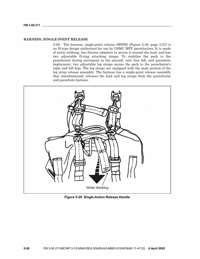
FM 3-05.211
5-26 FM 3-05.211/MCWP 3-15.6/NAVSEA SS400-AG-MMO-010/AFMAN 11-411(I) 6 April 2005
HARNESS, SINGLE-POINT RELEASE 5-29. The harness, single-point release (HSPR) (Figure 5-30, page 5-27) is an H-type design authorized for use by USMC MFF parachutists. It is made of nylon webbing, has friction adapters to secure it around the load, and has two adjustable D-ring attaching straps. To stabilize the pack to the parachutist during movement in the aircraft, exit, free fall, and parachute deployment, two adjustable leg straps secure the pack to the parachutist’s right and left legs. The leg straps are equipped with the male portion of the leg strap release assembly. The harness has a single-point release assembly that simultaneously releases the load and leg straps from the parachutist and parachute harness.
Figure 5-29. Single-Action Release Handle
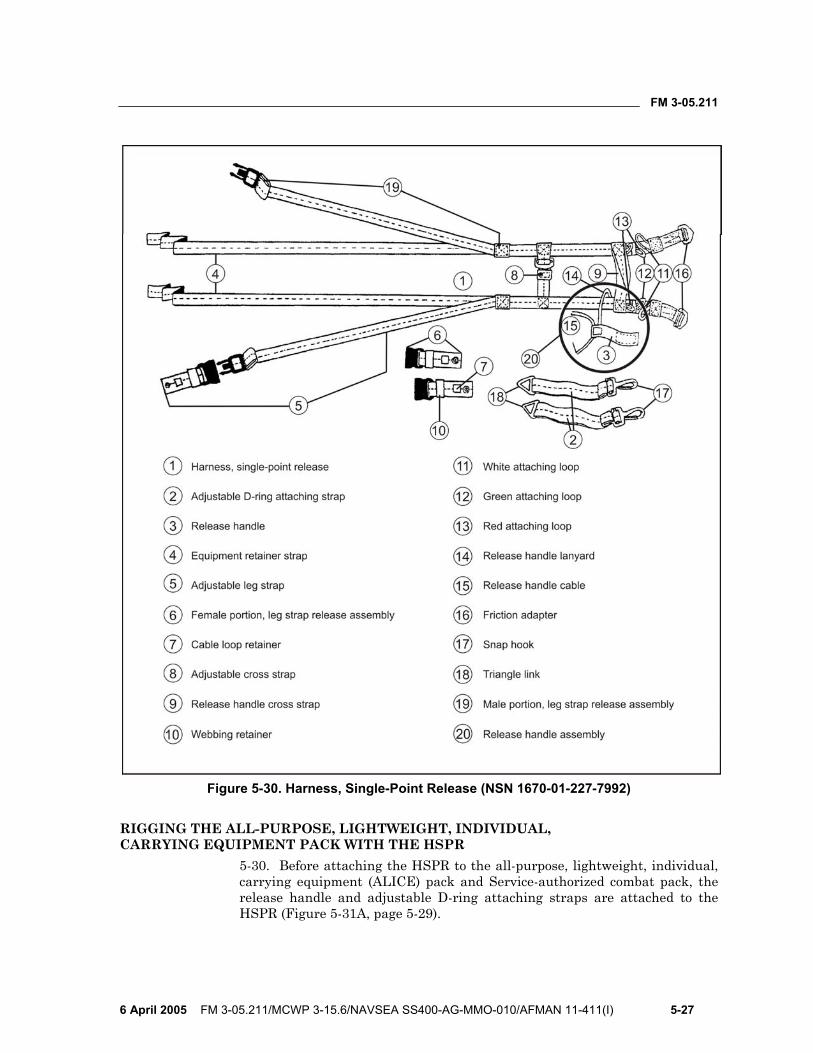
FM 3-05.211
6 April 2005 FM 3-05.211/MCWP 3-15.6/NAVSEA SS400-AG-MMO-010/AFMAN 11-411(I) 5-27
Figure 5-30. Harness, Single-Point Release (NSN 1670-01-227-7992)
RIGGING THE ALL-PURPOSE, LIGHTWEIGHT, INDIVIDUAL, CARRYING EQUIPMENT PACK WITH THE HSPR
5-30. Before attaching the HSPR to the all-purpose, lightweight, individual, carrying equipment (ALICE) pack and Service-authorized combat pack, the release handle and adjustable D-ring attaching straps are attached to the HSPR (Figure 5-31A, page 5-29).
FM 3-05.211
5-28 FM 3-05.211/MCWP 3-15.6/NAVSEA SS400-AG-MMO-010/AFMAN 11-411(I) 6 April 2005
5-31. The parachutist— • Routes the two release handle cables between the two plies of the
release handle cross strap. • Attaches the pile tape of the release handle to the hook tape attaching
tab located between the plies of the release handle cross strap. He ensures that the release handle lanyard is not misrouted.
• Places the triangle links of the adjustable D-ring attaching straps on top of the white attaching loops.
• Routes the white attaching loop up through the triangle link. • Routes the green attaching loop up through the white attaching loop. • Routes the red attaching loop up through the green attaching loop. • Routes the red attaching loop through the grommet on the female portion
of the leg strap release assembly. He ensures that the cable loop retainer on the female portion of the leg strap release assembly is facing up.
• Routes the release handle cable through the red attaching loop and then through the cable loop retainer. He repeats the process for the other strap.
• Turns the harness over so that the adjustable D-ring attaching straps are on the bottom.
• Places the ALICE pack on top of the harness so that the middle outer cargo pocket is placed between the release handle cross strap and the adjustable cross strap.
• Ensures the top of the pack is facing the equipment retainer straps (Figure 5-31B, page 5-29).
• Routes the equipment retainer straps underneath the top of the frame, crosses them on the back of the pack to form an X, then routes them underneath the frame and the backrest of the pack.
• Routes the equipment retainer straps through their appropriate friction adapters (a two- or three-finger quick release is optional; if used, the quick-release loop is secured to the harness with tape or a retainer band).
• S-rolls the excess webbing and secures it with retainer bands or tape (separates from the quick-release loop, if used).
• Attaches the HPT lowering line in the same way as with the modified H-harness for a front-mounted combat pack (Figure 5-31C). The 8-foot HPT lowering line is normally used for MFF operations. Terrain considerations may require use of a 15-foot HPT and is authorized. NOTE: Oscillation under canopy is dramatically increased when using the 15-foot HPT lowering line.
• Tightens the shoulder straps (Figure 5-31D). • Routes the adjustable leg straps around the pack and attaches the
male portion of the leg strap release assembly to the female portion of the leg strap release assembly, leaving it connected until it is time to attach the combat pack to the parachutist (Figure 5-31E). HSPR leg strap release (male portion) may be routed through the pack, between the frame and pack, on shorter parachutists to allow tighter attachment of the rucksack.
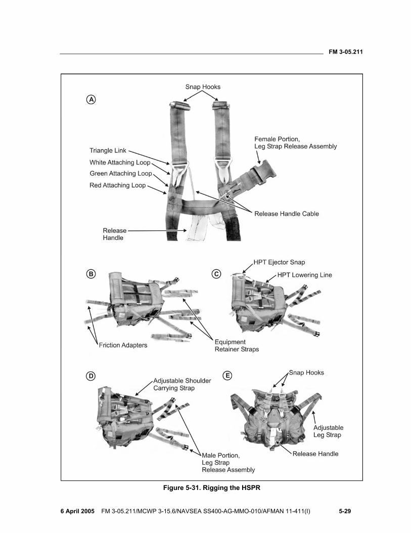
FM 3-05.211
6 April 2005 FM 3-05.211/MCWP 3-15.6/NAVSEA SS400-AG-MMO-010/AFMAN 11-411(I) 5-29
Figure 5-31. Rigging the HSPR
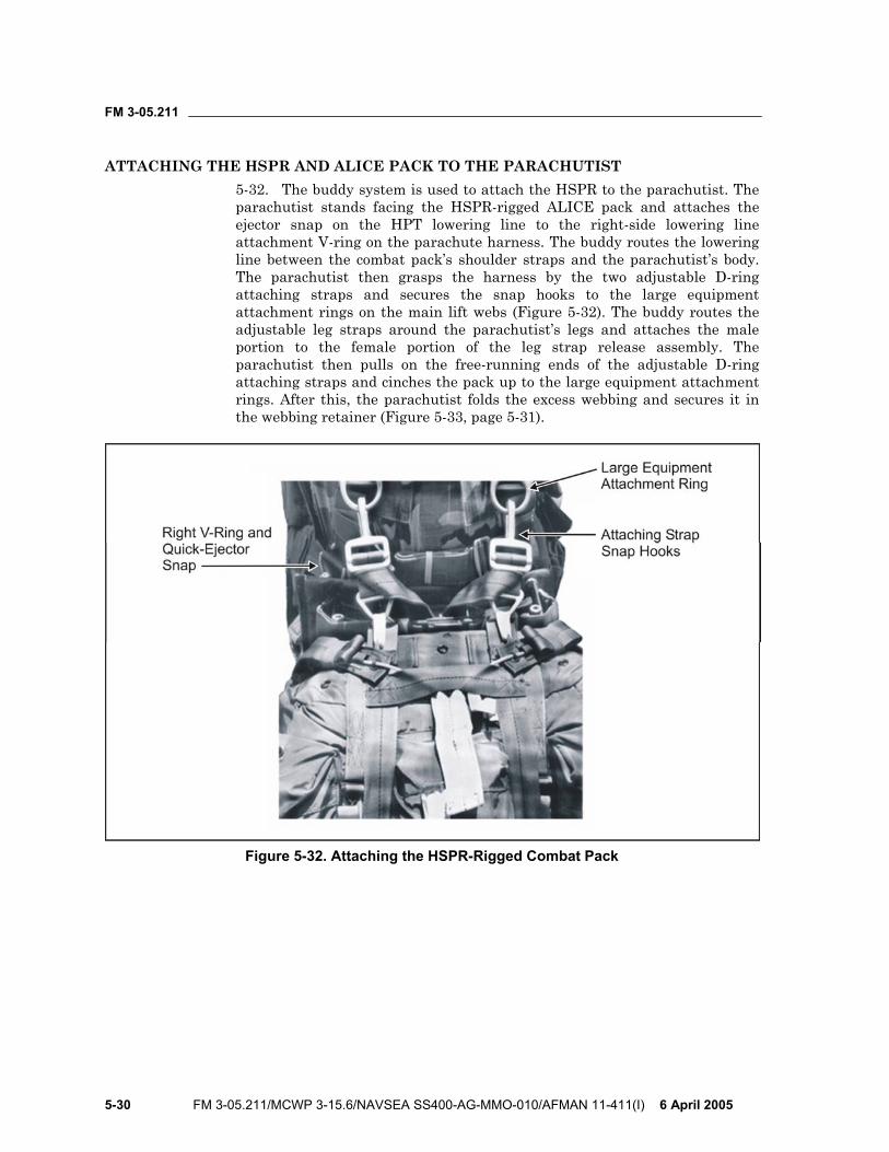
FM 3-05.211
5-30 FM 3-05.211/MCWP 3-15.6/NAVSEA SS400-AG-MMO-010/AFMAN 11-411(I) 6 April 2005
ATTACHING THE HSPR AND ALICE PACK TO THE PARACHUTIST 5-32. The buddy system is used to attach the HSPR to the parachutist. The parachutist stands facing the HSPR-rigged ALICE pack and attaches the ejector snap on the HPT lowering line to the right-side lowering line attachment V-ring on the parachute harness. The buddy routes the lowering line between the combat pack’s shoulder straps and the parachutist’s body. The parachutist then grasps the harness by the two adjustable D-ring attaching straps and secures the snap hooks to the large equipment attachment rings on the main lift webs (Figure 5-32). The buddy routes the adjustable leg straps around the parachutist’s legs and attaches the male portion to the female portion of the leg strap release assembly. The parachutist then pulls on the free-running ends of the adjustable D-ring attaching straps and cinches the pack up to the large equipment attachment rings. After this, the parachutist folds the excess webbing and secures it in the webbing retainer (Figure 5-33, page 5-31).
Figure 5-32. Attaching the HSPR-Rigged Combat Pack
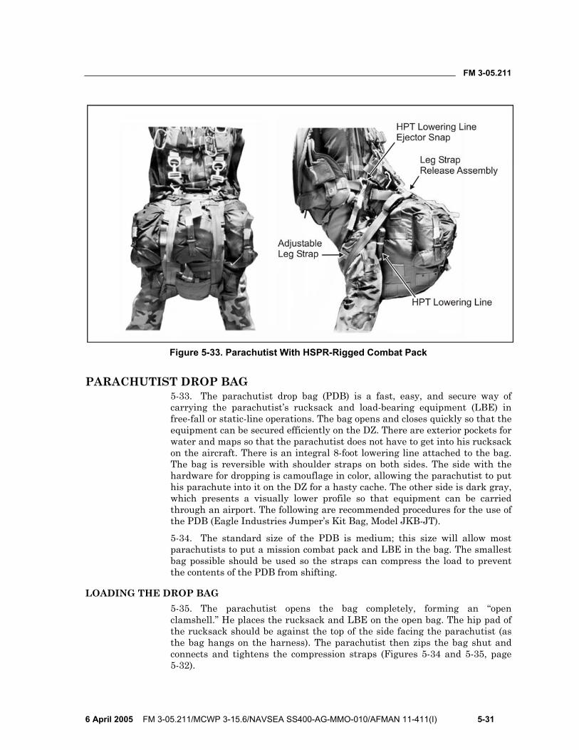
FM 3-05.211
6 April 2005 FM 3-05.211/MCWP 3-15.6/NAVSEA SS400-AG-MMO-010/AFMAN 11-411(I) 5-31
Figure 5-33. Parachutist With HSPR-Rigged Combat Pack
PARACHUTIST DROP BAG 5-33. The parachutist drop bag (PDB) is a fast, easy, and secure way of carrying the parachutist’s rucksack and load-bearing equipment (LBE) in free-fall or static-line operations. The bag opens and closes quickly so that the equipment can be secured efficiently on the DZ. There are exterior pockets for water and maps so that the parachutist does not have to get into his rucksack on the aircraft. There is an integral 8-foot lowering line attached to the bag. The bag is reversible with shoulder straps on both sides. The side with the hardware for dropping is camouflage in color, allowing the parachutist to put his parachute into it on the DZ for a hasty cache. The other side is dark gray, which presents a visually lower profile so that equipment can be carried through an airport. The following are recommended procedures for the use of the PDB (Eagle Industries Jumper’s Kit Bag, Model JKB-JT).
5-34. The standard size of the PDB is medium; this size will allow most parachutists to put a mission combat pack and LBE in the bag. The smallest bag possible should be used so the straps can compress the load to prevent the contents of the PDB from shifting.
LOADING THE DROP BAG 5-35. The parachutist opens the bag completely, forming an “open clamshell.” He places the rucksack and LBE on the open bag. The hip pad of the rucksack should be against the top of the side facing the parachutist (as the bag hangs on the harness). The parachutist then zips the bag shut and connects and tightens the compression straps (Figures 5-34 and 5-35, page 5-32).
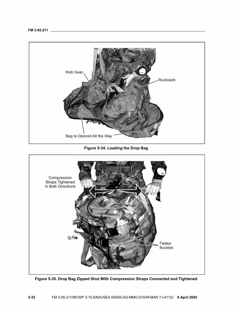
FM 3-05.211
5-32 FM 3-05.211/MCWP 3-15.6/NAVSEA SS400-AG-MMO-010/AFMAN 11-411(I) 6 April 2005
Figure 5-34. Loading the Drop Bag
Figure 5-35. Drop Bag Zipped Shut With Compression Straps Connected and Tightened
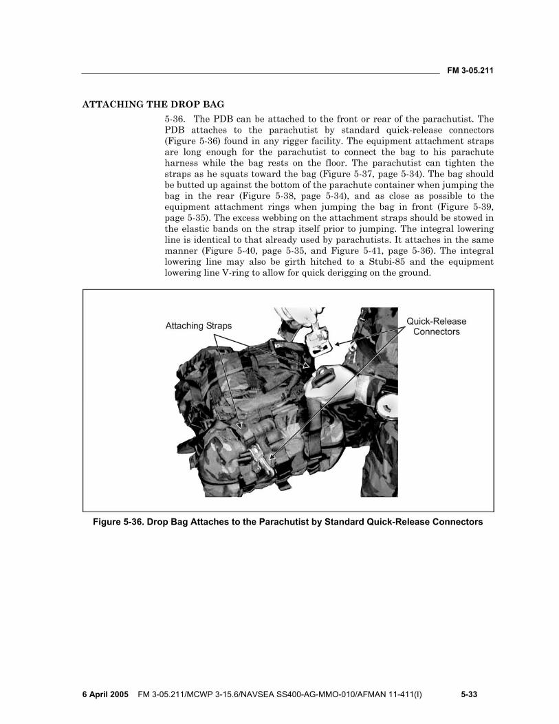
FM 3-05.211
6 April 2005 FM 3-05.211/MCWP 3-15.6/NAVSEA SS400-AG-MMO-010/AFMAN 11-411(I) 5-33
ATTACHING THE DROP BAG 5-36. The PDB can be attached to the front or rear of the parachutist. The PDB attaches to the parachutist by standard quick-release connectors (Figure 5-36) found in any rigger facility. The equipment attachment straps are long enough for the parachutist to connect the bag to his parachute harness while the bag rests on the floor. The parachutist can tighten the straps as he squats toward the bag (Figure 5-37, page 5-34). The bag should be butted up against the bottom of the parachute container when jumping the bag in the rear (Figure 5-38, page 5-34), and as close as possible to the equipment attachment rings when jumping the bag in front (Figure 5-39, page 5-35). The excess webbing on the attachment straps should be stowed in the elastic bands on the strap itself prior to jumping. The integral lowering line is identical to that already used by parachutists. It attaches in the same manner (Figure 5-40, page 5-35, and Figure 5-41, page 5-36). The integral lowering line may also be girth hitched to a Stubi-85 and the equipment lowering line V-ring to allow for quick derigging on the ground.
Figure 5-36. Drop Bag Attaches to the Parachutist by Standard Quick-Release Connectors
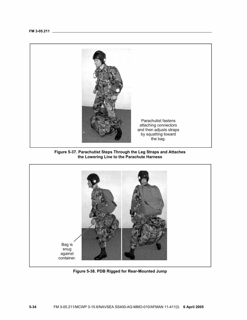
FM 3-05.211
5-34 FM 3-05.211/MCWP 3-15.6/NAVSEA SS400-AG-MMO-010/AFMAN 11-411(I) 6 April 2005
Figure 5-37. Parachutist Steps Through the Leg Straps and Attaches the Lowering Line to the Parachute Harness
Figure 5-38. PDB Rigged for Rear-Mounted Jump
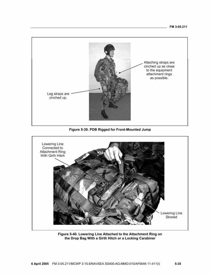
FM 3-05.211
6 April 2005 FM 3-05.211/MCWP 3-15.6/NAVSEA SS400-AG-MMO-010/AFMAN 11-411(I) 5-35
Figure 5-39. PDB Rigged for Front-Mounted Jump
Figure 5-40. Lowering Line Attached to the Attachment Ring on the Drop Bag With a Girth Hitch or a Locking Carabiner
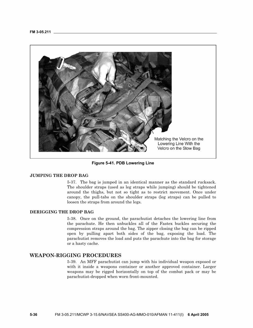
FM 3-05.211
5-36 FM 3-05.211/MCWP 3-15.6/NAVSEA SS400-AG-MMO-010/AFMAN 11-411(I) 6 April 2005
Figure 5-41. PDB Lowering Line
JUMPING THE DROP BAG 5-37. The bag is jumped in an identical manner as the standard rucksack. The shoulder straps (used as leg straps while jumping) should be tightened around the thighs, but not so tight as to restrict movement. Once under canopy, the pull-tabs on the shoulder straps (leg straps) can be pulled to loosen the straps from around the legs.
DERIGGING THE DROP BAG 5-38. Once on the ground, the parachutist detaches the lowering line from the parachute. He then unbuckles all of the Fastex buckles securing the compression straps around the bag. The zipper closing the bag can be ripped open by pulling apart both sides of the bag, exposing the load. The parachutist removes the load and puts the parachute into the bag for storage or a hasty cache.
WEAPON-RIGGING PROCEDURES 5-39. An MFF parachutist can jump with his individual weapon exposed or with it inside a weapons container or another approved container. Larger weapons may be rigged horizontally on top of the combat pack or may be parachutist-dropped when worn front-mounted.
FM 3-05.211
6 April 2005 FM 3-05.211/MCWP 3-15.6/NAVSEA SS400-AG-MMO-010/AFMAN 11-411(I) 5-37
EXPOSED WEAPONS CONSIDERATIONS 5-40. If the commander decides that parachutists are to jump with weapons exposed, he must consider the increased risk of injury to the parachutists. To minimize the risks of jumping with exposed weapons, the commander should—
• Consider the proficiency and experience level of the parachutists. • Conduct a thorough risk assessment that addresses the following risks
associated with jumping exposed weapons: Interference with the oxygen system or AOD. Interference with the parachutist’s exit from the aircraft. Stability of the parachutist while in free fall. Ability of the parachutist to perform pull procedures. Ability of the parachutist to perform emergency procedures. Deployment of the parachute. Entanglement of the weapon with another parachutist’s parachute should a midair entanglement occur. Ability of the parachutist to perform a parachute landing fall (PLF). Injury to the parachutist during landing. Damage to the weapon upon landing or when dragged on the ground.
M16-SERIES AND M4 CARBINE-SERIES RIFLES 5-41. To prepare the M16-series and M4 carbine-series rifles for jumping (Figure 5-42, page 5-38), the parachutist should—
• Extend the weapon sling all the way and tape the sling keeper in place. NOTE: A padded sling should not be used as it may interfere with emergency procedures when rigged on the parachutist. • Pad and tape the side-mounted bolt assist and the operating handle. • Pad and tape the muzzle and the sights to avoid possible entanglement
with the parachute suspension lines or dirt clogging the weapon upon landing.
• Insert the magazine and tape it to the receiver, including the ejector port cover, to prevent loss of the magazine and to keep debris from entering the bolt area.
• Tape the hand guards to prevent their loss during free fall or upon landing.
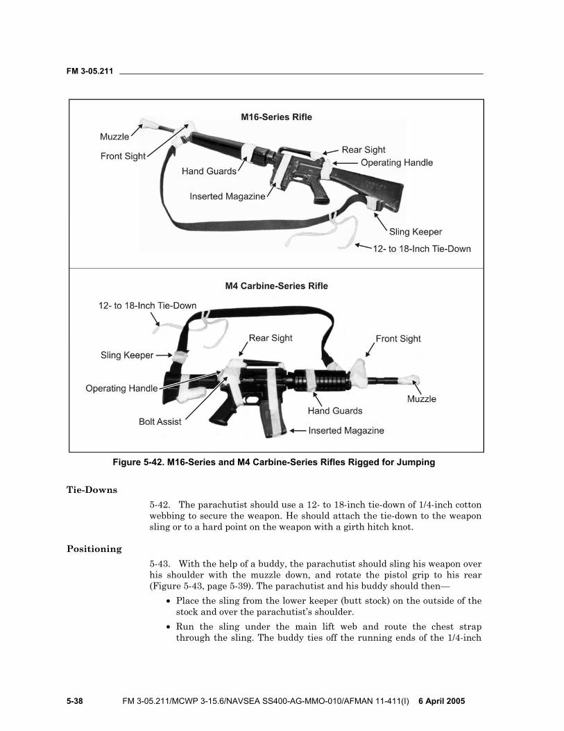
FM 3-05.211
5-38 FM 3-05.211/MCWP 3-15.6/NAVSEA SS400-AG-MMO-010/AFMAN 11-411(I) 6 April 2005
Figure 5-42. M16-Series and M4 Carbine-Series Rifles Rigged for Jumping
Tie-Downs 5-42. The parachutist should use a 12- to 18-inch tie-down of 1/4-inch cotton webbing to secure the weapon. He should attach the tie-down to the weapon sling or to a hard point on the weapon with a girth hitch knot.
Positioning 5-43. With the help of a buddy, the parachutist should sling his weapon over his shoulder with the muzzle down, and rotate the pistol grip to his rear (Figure 5-43, page 5-39). The parachutist and his buddy should then—
• Place the sling from the lower keeper (butt stock) on the outside of the stock and over the parachutist’s shoulder.
• Run the sling under the main lift web and route the chest strap through the sling. The buddy ties off the running ends of the 1/4-inch
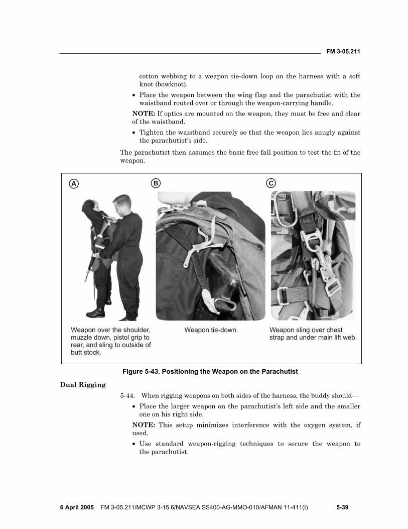
FM 3-05.211
6 April 2005 FM 3-05.211/MCWP 3-15.6/NAVSEA SS400-AG-MMO-010/AFMAN 11-411(I) 5-39
cotton webbing to a weapon tie-down loop on the harness with a soft knot (bowknot).
• Place the weapon between the wing flap and the parachutist with the waistband routed over or through the weapon-carrying handle.
NOTE: If optics are mounted on the weapon, they must be free and clear of the waistband. • Tighten the waistband securely so that the weapon lies snugly against
the parachutist’s side. The parachutist then assumes the basic free-fall position to test the fit of the weapon.
Figure 5-43. Positioning the Weapon on the Parachutist
Dual Rigging 5-44. When rigging weapons on both sides of the harness, the buddy should—
• Place the larger weapon on the parachutist’s left side and the smaller one on his right side.
NOTE: This setup minimizes interference with the oxygen system, if used. • Use standard weapon-rigging techniques to secure the weapon to
the parachutist.
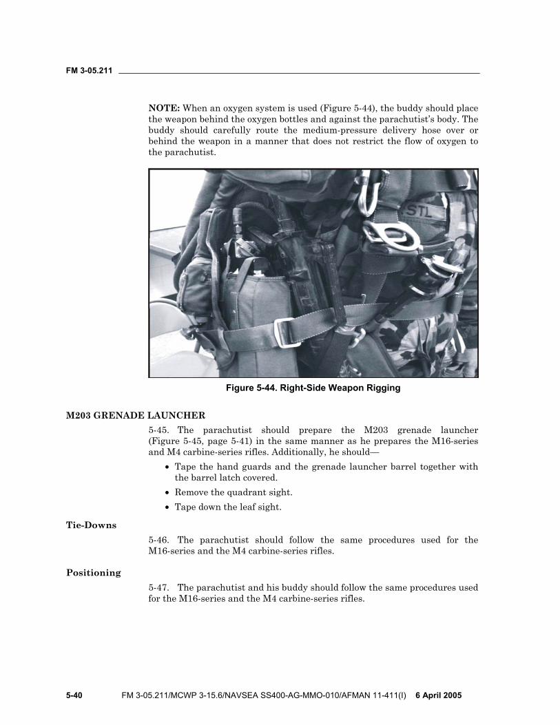
FM 3-05.211
5-40 FM 3-05.211/MCWP 3-15.6/NAVSEA SS400-AG-MMO-010/AFMAN 11-411(I) 6 April 2005
NOTE: When an oxygen system is used (Figure 5-44), the buddy should place the weapon behind the oxygen bottles and against the parachutist’s body. The buddy should carefully route the medium-pressure delivery hose over or behind the weapon in a manner that does not restrict the flow of oxygen to the parachutist.
Figure 5-44. Right-Side Weapon Rigging
M203 GRENADE LAUNCHER 5-45. The parachutist should prepare the M203 grenade launcher (Figure 5-45, page 5-41) in the same manner as he prepares the M16-series and M4 carbine-series rifles. Additionally, he should—
• Tape the hand guards and the grenade launcher barrel together with the barrel latch covered.
• Remove the quadrant sight. • Tape down the leaf sight.
Tie-Downs 5-46. The parachutist should follow the same procedures used for the M16-series and the M4 carbine-series rifles.
Positioning 5-47. The parachutist and his buddy should follow the same procedures used for the M16-series and the M4 carbine-series rifles.
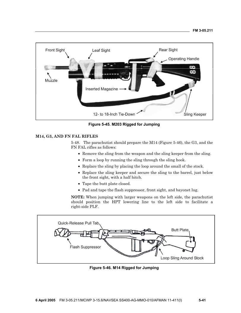
FM 3-05.211
6 April 2005 FM 3-05.211/MCWP 3-15.6/NAVSEA SS400-AG-MMO-010/AFMAN 11-411(I) 5-41
Figure 5-45. M203 Rigged for Jumping
M14, G3, AND FN FAL RIFLES 5-48. The parachutist should prepare the M14 (Figure 5-46), the G3, and the FN FAL rifles as follows:
• Remove the sling from the weapon and the sling keeper from the sling. • Form a loop by running the sling through the sling hook. • Replace the sling by placing the loop around the small of the stock. • Replace the sling keeper and secure the sling to the barrel, just below
the front sight, with a half hitch. • Tape the butt plate closed. • Pad and tape the flash suppressor, front sight, and bayonet lug.
NOTE: When jumping with larger weapons on the left side, the parachutist should position the HPT lowering line to the left side to facilitate a right-side PLF.
Figure 5-46. M14 Rigged for Jumping
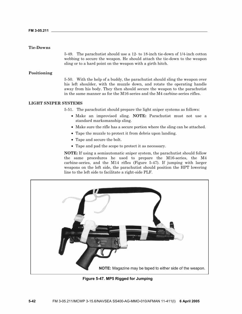
FM 3-05.211
5-42 FM 3-05.211/MCWP 3-15.6/NAVSEA SS400-AG-MMO-010/AFMAN 11-411(I) 6 April 2005
Tie-Downs 5-49. The parachutist should use a 12- to 18-inch tie-down of 1/4-inch cotton webbing to secure the weapon. He should attach the tie-down to the weapon sling or to a hard point on the weapon with a girth hitch.
Positioning 5-50. With the help of a buddy, the parachutist should sling the weapon over his left shoulder, with the muzzle down, and rotate the operating handle away from his body. They then should secure the weapon to the parachutist in the same manner as for the M16-series and the M4 carbine-series rifles.
LIGHT SNIPER SYSTEMS 5-51. The parachutist should prepare the light sniper systems as follows:
• Make an improvised sling. NOTE: Parachutist must not use a standard marksmanship sling.
• Make sure the rifle has a secure portion where the sling can be attached. • Tape the muzzle to protect it from debris upon landing. • Tape and secure the bolt. • Tape and pad the scope to protect it as necessary.
NOTE: If using a semiautomatic sniper system, the parachutist should follow the same procedures he used to prepare the M16-series, the M4 carbine-series, and the M14 rifles (Figure 5-47). If jumping with larger weapons on the left side, the parachutist should position the HPT lowering line to the left side to facilitate a right-side PLF.
Figure 5-47. MP5 Rigged for Jumping
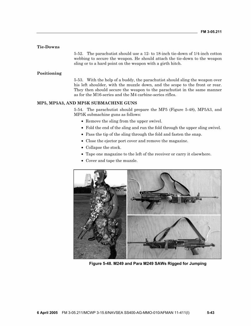
FM 3-05.211
6 April 2005 FM 3-05.211/MCWP 3-15.6/NAVSEA SS400-AG-MMO-010/AFMAN 11-411(I) 5-43
Tie-Downs 5-52. The parachutist should use a 12- to 18-inch tie-down of 1/4-inch cotton webbing to secure the weapon. He should attach the tie-down to the weapon sling or to a hard point on the weapon with a girth hitch.
Positioning 5-53. With the help of a buddy, the parachutist should sling the weapon over his left shoulder, with the muzzle down, and the scope to the front or rear. They then should secure the weapon to the parachutist in the same manner as for the M16-series and the M4 carbine-series rifles.
MP5, MP5A3, AND MP5K SUBMACHINE GUNS 5-54. The parachutist should prepare the MP5 (Figure 5-48), MP5A3, and MP5K submachine guns as follows:
• Remove the sling from the upper swivel. • Fold the end of the sling and run the fold through the upper sling swivel. • Pass the tip of the sling through the fold and fasten the snap. • Close the ejector port cover and remove the magazine. • Collapse the stock. • Tape one magazine to the left of the receiver or carry it elsewhere. • Cover and tape the muzzle.
Figure 5-48. M249 and Para M249 SAWs Rigged for Jumping
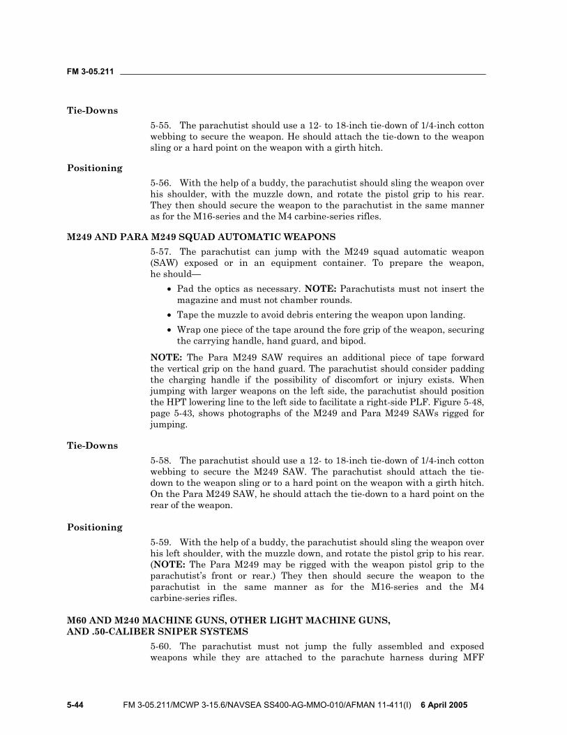
FM 3-05.211
5-44 FM 3-05.211/MCWP 3-15.6/NAVSEA SS400-AG-MMO-010/AFMAN 11-411(I) 6 April 2005
Tie-Downs 5-55. The parachutist should use a 12- to 18-inch tie-down of 1/4-inch cotton webbing to secure the weapon. He should attach the tie-down to the weapon sling or a hard point on the weapon with a girth hitch.
Positioning 5-56. With the help of a buddy, the parachutist should sling the weapon over his shoulder, with the muzzle down, and rotate the pistol grip to his rear. They then should secure the weapon to the parachutist in the same manner as for the M16-series and the M4 carbine-series rifles.
M249 AND PARA M249 SQUAD AUTOMATIC WEAPONS 5-57. The parachutist can jump with the M249 squad automatic weapon (SAW) exposed or in an equipment container. To prepare the weapon, he should—
• Pad the optics as necessary. NOTE: Parachutists must not insert the magazine and must not chamber rounds.
• Tape the muzzle to avoid debris entering the weapon upon landing. • Wrap one piece of the tape around the fore grip of the weapon, securing
the carrying handle, hand guard, and bipod. NOTE: The Para M249 SAW requires an additional piece of tape forward the vertical grip on the hand guard. The parachutist should consider padding the charging handle if the possibility of discomfort or injury exists. When jumping with larger weapons on the left side, the parachutist should position the HPT lowering line to the left side to facilitate a right-side PLF. Figure 5-48, page 5-43, shows photographs of the M249 and Para M249 SAWs rigged for jumping.
Tie-Downs 5-58. The parachutist should use a 12- to 18-inch tie-down of 1/4-inch cotton webbing to secure the M249 SAW. The parachutist should attach the tie-down to the weapon sling or to a hard point on the weapon with a girth hitch. On the Para M249 SAW, he should attach the tie-down to a hard point on the rear of the weapon.
Positioning 5-59. With the help of a buddy, the parachutist should sling the weapon over his left shoulder, with the muzzle down, and rotate the pistol grip to his rear. (NOTE: The Para M249 may be rigged with the weapon pistol grip to the parachutist’s front or rear.) They then should secure the weapon to the parachutist in the same manner as for the M16-series and the M4 carbine-series rifles.
M60 AND M240 MACHINE GUNS, OTHER LIGHT MACHINE GUNS, AND .50-CALIBER SNIPER SYSTEMS
5-60. The parachutist must not jump the fully assembled and exposed weapons while they are attached to the parachute harness during MFF
FM 3-05.211
6 April 2005 FM 3-05.211/MCWP 3-15.6/NAVSEA SS400-AG-MMO-010/AFMAN 11-411(I) 5-45
operations. The parachutist may break the weapons down and pack them inside the combat pack, PDB, or a horizontally mounted kit bag with an H-harness. They may also be jumped exposed horizontally attached to a front-mounted combat pack or container.
PISTOLS 5-61. The parachutist can jump with a pistol in a shoulder holster or in an equipment container. The parachutist should wear a shoulder holster under his jumpsuit or other protective clothing. He should secure the pistol in the holster by taping the holster closed or by using a lanyard.
AT-4, 84-MILLIMETER CARL GUSTAF RECOILLESS RIFLE, AND OTHER LIGHT ANTIARMOR WEAPONS
5-62. The recommended procedure for rigging the AT-4 and 84-millimeter (mm) Carl Gustaf recoilless rifle (RCLR) is to front-mount the weapon horizontally on top of a combat pack or a PDB, or in an H-harness. This arrangement limits the parachutist to a ramp-only exit because of the rigged width of the parachutist. To rig these weapons for a front-mounted jump on top of a combat pack or a PDB, the parachutist—
• Tapes and pads the end of the launch tube to prevent debris from entering the tube upon landing. If the launch tube has removable end caps, he tapes and secures them to the launch tube (Figure 5-49).
• Tapes the sling securely to the launch tube (Figure 5-49). • Pads and tapes the weapon sights and the trigger mechanism
(Figure 5-49).
Figure 5-49. AT-4 and 84-mm Carl Gustaf Rigged for Jumping
• Mounts the weapon system on top of the combat pack or PDB. He routes the H-harness, Spider harness, or PDB vertical compression straps over the weapon and through the carrying handle of the Carl Gustaf or through the sling of the AT-4, and tightens securely (Figure 5-50, page 5-46).
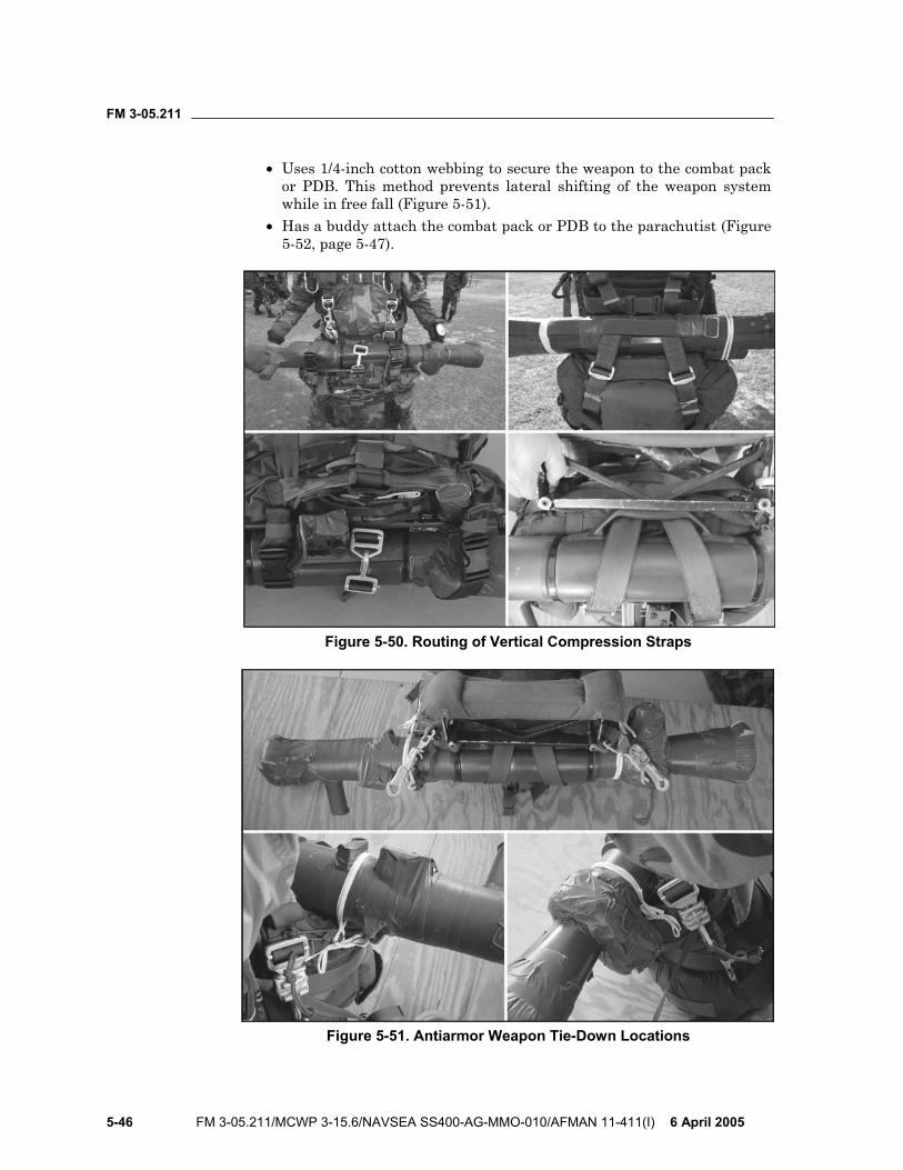
FM 3-05.211
5-46 FM 3-05.211/MCWP 3-15.6/NAVSEA SS400-AG-MMO-010/AFMAN 11-411(I) 6 April 2005
• Uses 1/4-inch cotton webbing to secure the weapon to the combat pack or PDB. This method prevents lateral shifting of the weapon system while in free fall (Figure 5-51).
• Has a buddy attach the combat pack or PDB to the parachutist (Figure 5-52, page 5-47).
Figure 5-50. Routing of Vertical Compression Straps
Figure 5-51. Antiarmor Weapon Tie-Down Locations
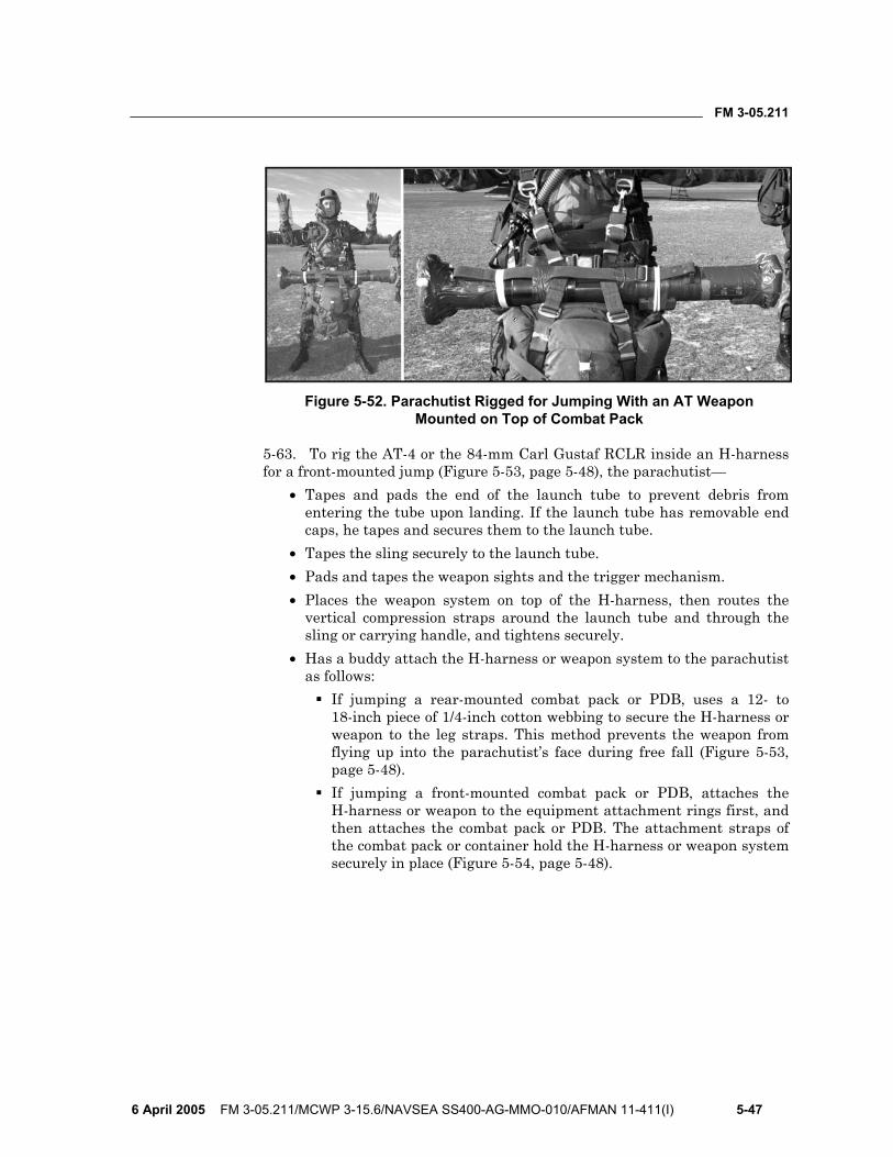
FM 3-05.211
6 April 2005 FM 3-05.211/MCWP 3-15.6/NAVSEA SS400-AG-MMO-010/AFMAN 11-411(I) 5-47
Figure 5-52. Parachutist Rigged for Jumping With an AT Weapon Mounted on Top of Combat Pack
5-63. To rig the AT-4 or the 84-mm Carl Gustaf RCLR inside an H-harness for a front-mounted jump (Figure 5-53, page 5-48), the parachutist—
• Tapes and pads the end of the launch tube to prevent debris from entering the tube upon landing. If the launch tube has removable end caps, he tapes and secures them to the launch tube.
• Tapes the sling securely to the launch tube. • Pads and tapes the weapon sights and the trigger mechanism. • Places the weapon system on top of the H-harness, then routes the
vertical compression straps around the launch tube and through the sling or carrying handle, and tightens securely.
• Has a buddy attach the H-harness or weapon system to the parachutist as follows:
If jumping a rear-mounted combat pack or PDB, uses a 12- to 18-inch piece of 1/4-inch cotton webbing to secure the H-harness or weapon to the leg straps. This method prevents the weapon from flying up into the parachutist’s face during free fall (Figure 5-53, page 5-48).
If jumping a front-mounted combat pack or PDB, attaches the H-harness or weapon to the equipment attachment rings first, and then attaches the combat pack or PDB. The attachment straps of the combat pack or container hold the H-harness or weapon system securely in place (Figure 5-54, page 5-48).
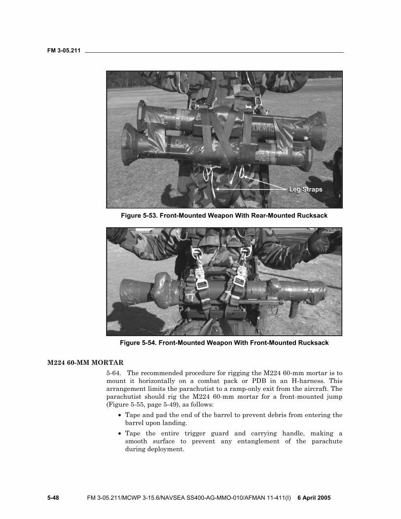
FM 3-05.211
5-48 FM 3-05.211/MCWP 3-15.6/NAVSEA SS400-AG-MMO-010/AFMAN 11-411(I) 6 April 2005
Figure 5-53. Front-Mounted Weapon With Rear-Mounted Rucksack
Figure 5-54. Front-Mounted Weapon With Front-Mounted Rucksack
M224 60-MM MORTAR 5-64. The recommended procedure for rigging the M224 60-mm mortar is to mount it horizontally on a combat pack or PDB in an H-harness. This arrangement limits the parachutist to a ramp-only exit from the aircraft. The parachutist should rig the M224 60-mm mortar for a front-mounted jump (Figure 5-55, page 5-49), as follows:
• Tape and pad the end of the barrel to prevent debris from entering the barrel upon landing.
• Tape the entire trigger guard and carrying handle, making a smooth surface to prevent any entanglement of the parachute during deployment.
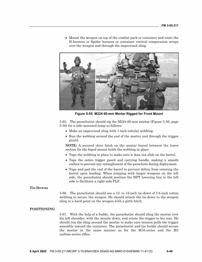
FM 3-05.211
6 April 2005 FM 3-05.211/MCWP 3-15.6/NAVSEA SS400-AG-MMO-010/AFMAN 11-411(I) 5-49
• Mount the weapon on top of the combat pack or container and route the H-harness or Spider harness or container vertical compression straps over the weapon and through the improvised sling.
Figure 5-55. M224 60-mm Mortar Rigged for Front Mount
5-65. The parachutist should rig the M224 60-mm mortar (Figure 5-56, page 5-50) for a side-mounted jump as follows:
• Make an improvised sling with 1-inch tubular webbing. • Run the webbing around the end of the mortar and through the trigger
guard. NOTE: A secured clove hitch on the mortar barrel between the lower section for the bipod mount holds the webbing in place. • Tape the webbing in place to make sure it does not slide on the barrel. • Tape the entire trigger guard and carrying handle, making a smooth
surface to prevent any entanglement of the parachute during deployment. • Tape and pad the end of the barrel to prevent debris from entering the
barrel upon landing. When jumping with larger weapons on the left side, the parachutist should position the HPT lowering line to the left side to facilitate a right-side PLF.
Tie-Downs 5-66. The parachutist should use a 12- to 18-inch tie-down of 1/4-inch cotton webbing to secure the weapon. He should attach the tie-down to the weapon sling or a hard point on the weapon with a girth hitch.
POSITIONING 5-67. With the help of a buddy, the parachutist should sling the mortar over his left shoulder, with the muzzle down, and rotate the trigger to his rear. He should run the sling around the mortar to make sure tension pulls the trigger assembly toward the container. The parachutist and his buddy should secure the mortar in the same manner as for the M16-series and the M4 carbine-series rifles.
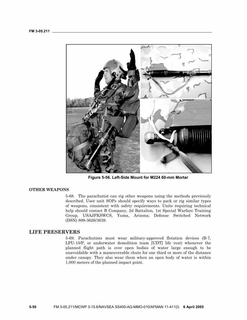
FM 3-05.211
5-50 FM 3-05.211/MCWP 3-15.6/NAVSEA SS400-AG-MMO-010/AFMAN 11-411(I) 6 April 2005
Figure 5-56. Left-Side Mount for M224 60-mm Mortar
OTHER WEAPONS 5-68. The parachutist can rig other weapons using the methods previously described. User unit SOPs should specify ways to pack or rig similar types of weapons, consistent with safety requirements. Units requiring technical help should contact B Company, 2d Battalion, 1st Special Warfare Training Group, USAJFKSWCS, Yuma, Arizona; Defense Switched Network (DSN) 899-3626/3639.
LIFE PRESERVERS 5-69. Parachutists must wear military-approved flotation devices (B-7, LPU-10/P, or underwater demolition team [UDT] life vest) whenever the planned flight path is over open bodies of water large enough to be unavoidable with a maneuverable chute for one third or more of the distance under canopy. They also wear them when an open body of water is within 1,000 meters of the planned impact point.
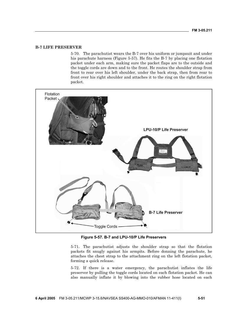
FM 3-05.211
6 April 2005 FM 3-05.211/MCWP 3-15.6/NAVSEA SS400-AG-MMO-010/AFMAN 11-411(I) 5-51
B-7 LIFE PRESERVER 5-70. The parachutist wears the B-7 over his uniform or jumpsuit and under his parachute harness (Figure 5-57). He fits the B-7 by placing one flotation packet under each arm, making sure the packet flaps are to the outside and the toggle cords are down and to the front. He routes the shoulder strap from front to rear over his left shoulder, under the back strap, then from rear to front over his right shoulder and attaches it to the ring on the right flotation packet.
Figure 5-57. B-7 and LPU-10/P Life Preservers
5-71. The parachutist adjusts the shoulder strap so that the flotation packets fit snugly against his armpits. Before donning the parachute, he attaches the chest strap to the attachment ring on the left flotation packet, forming a quick release.
5-72. If there is a water emergency, the parachutist inflates the life preserver by pulling the toggle cords located on each flotation packet. He can also manually inflate it by blowing into the rubber hose located on each
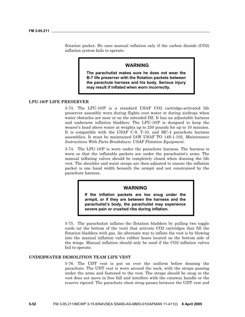
FM 3-05.211
5-52 FM 3-05.211/MCWP 3-15.6/NAVSEA SS400-AG-MMO-010/AFMAN 11-411(I) 6 April 2005
flotation packet. He uses manual inflation only if the carbon dioxide (CO2) inflation system fails to operate.
WARNING The parachutist makes sure he does not wear the B-7 life preserver with the flotation packets between the parachute harness and his body. Serious injury may result if inflated when worn incorrectly.
LPU-10/P LIFE PRESERVER 5-73. The LPU-10/P is a standard USAF CO2 cartridge-activated life preserver assembly worn during flights over water or during airdrops when water obstacles are near or on the intended DZ. It has an adjustable harness and underarm inflation bladders. The LPU-10/P is designed to keep the wearer’s head above water at weights up to 250 pounds for up to 10 minutes. It is compatible with the USAF C-9, T-10, and MC-4 parachute harness assemblies. It must be maintained IAW USAF TO 14S-1-102, Maintenance Instructions With Parts Breakdown: USAF Flotation Equipment.
5-74. The LPU-10/P is worn under the parachute harness. The harness is worn so that the inflatable packets are under the parachutist’s arms. The manual inflating valves should be completely closed when donning the life vest. The shoulder and waist straps are then adjusted to ensure the inflation packet is one hand width beneath the armpit and not constrained by the parachute harness.
WARNING If the inflation packets are too snug under the armpit, or if they are between the harness and the parachutist’s body, the parachutist may experience severe pain or crushed ribs during inflation.
5-75. The parachutist inflates the flotation bladders by pulling two toggle cords (at the bottom of the vest) that activate CO2 cartridges that fill the flotation bladders with gas. An alternate way to inflate the vest is by blowing into the manual inflation valve rubber hoses located on the bottom side of the wings. Manual inflation should only be used if the CO2 inflation valves fail to operate.
UNDERWATER DEMOLITION TEAM LIFE VEST 5-76. The UDT vest is put on over the uniform before donning the parachute. The UDT vest is worn around the neck, with the straps passing under the arms and fastened to the vest. The straps should be snug so the vest does not move in free fall and interfere with the cutaway handle or the reserve ripcord. The parachute chest strap passes between the UDT vest and
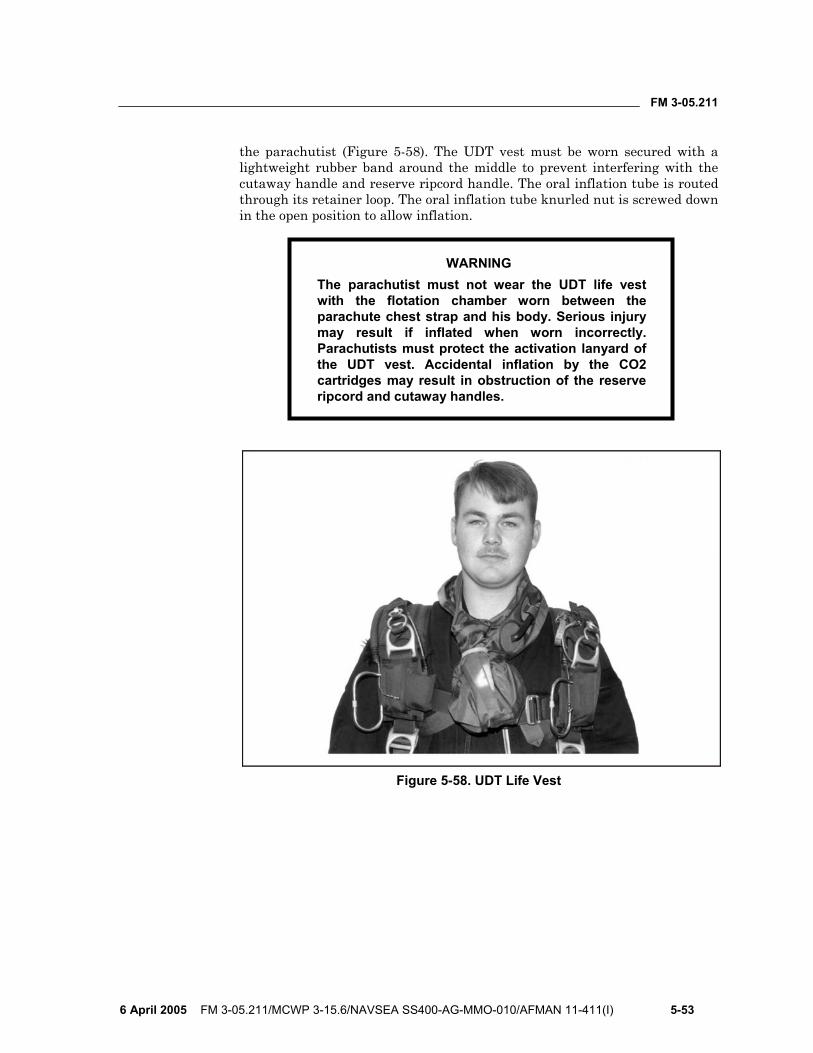
FM 3-05.211
6 April 2005 FM 3-05.211/MCWP 3-15.6/NAVSEA SS400-AG-MMO-010/AFMAN 11-411(I) 5-53
the parachutist (Figure 5-58). The UDT vest must be worn secured with a lightweight rubber band around the middle to prevent interfering with the cutaway handle and reserve ripcord handle. The oral inflation tube is routed through its retainer loop. The oral inflation tube knurled nut is screwed down in the open position to allow inflation.
WARNING The parachutist must not wear the UDT life vest with the flotation chamber worn between the parachute chest strap and his body. Serious injury may result if inflated when worn incorrectly. Parachutists must protect the activation lanyard of the UDT vest. Accidental inflation by the CO2 cartridges may result in obstruction of the reserve ripcord and cutaway handles.
Figure 5-58. UDT Life Vest

This page intentionally left blank.
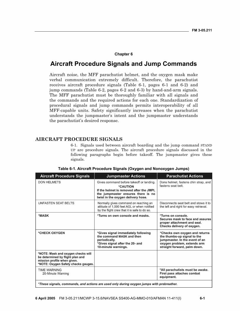
FM 3-05.211
6 April 2005 FM 3-05.211/MCWP 3-15.6/NAVSEA SS400-AG-MMO-010/AFMAN 11-411(I) 6-1
Chapter 6
Aircraft Procedure Signals and Jump Commands Aircraft noise, the MFF parachutist helmet, and the oxygen mask make verbal communication extremely difficult. Therefore, the parachutist receives aircraft procedure signals (Table 6-1, pages 6-1 and 6-2) and jump commands (Table 6-2, pages 6-2 and 6-3) by hand-and-arm signals. The MFF parachutist must be thoroughly familiar with all signals and the commands and the required actions for each one. Standardization of procedural signals and jump commands permits interoperability of all MFF-capable units. Safety significantly increases when the parachutist understands the jumpmaster’s intent and the jumpmaster understands the parachutist’s desired response.
AIRCRAFT PROCEDURE SIGNALS 6-1. Signals used between aircraft boarding and the jump command STAND UP are procedure signals. The aircraft procedure signals discussed in the following paragraphs begin before takeoff. The jumpmaster gives these signals.
Table 6-1. Aircraft Procedure Signals (Oxygen and Nonoxygen Jumps)
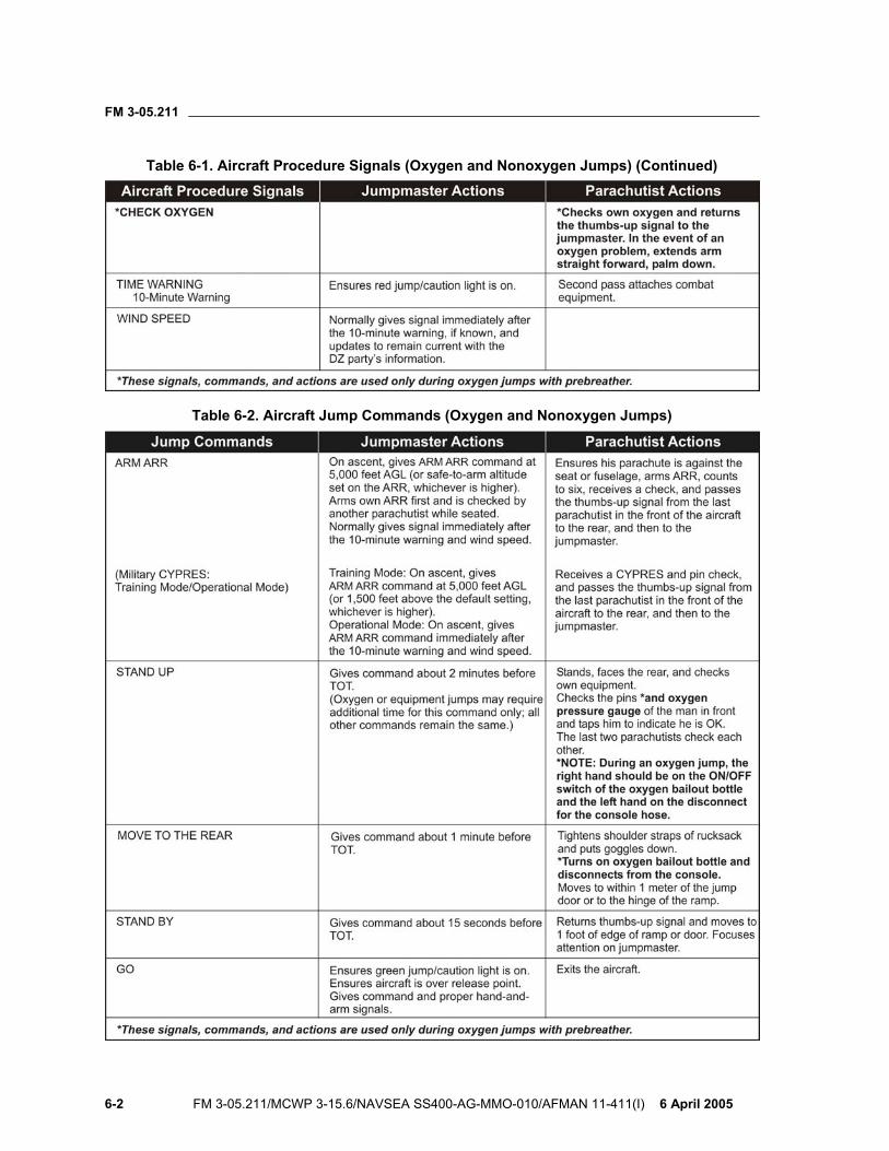
FM 3-05.211
6-2 FM 3-05.211/MCWP 3-15.6/NAVSEA SS400-AG-MMO-010/AFMAN 11-411(I) 6 April 2005
Table 6-1. Aircraft Procedure Signals (Oxygen and Nonoxygen Jumps) (Continued)
Table 6-2. Aircraft Jump Commands (Oxygen and Nonoxygen Jumps)
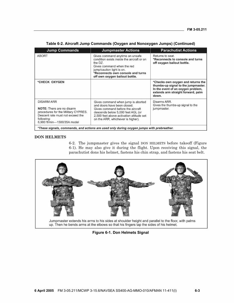
FM 3-05.211
6 April 2005 FM 3-05.211/MCWP 3-15.6/NAVSEA SS400-AG-MMO-010/AFMAN 11-411(I) 6-3
Table 6-2. Aircraft Jump Commands (Oxygen and Nonoxygen Jumps) (Continued)
DON HELMETS 6-2. The jumpmaster gives the signal DON HELMETS before takeoff (Figure 6-1). He may also give it during the flight. Upon receiving this signal, the parachutist dons his helmet, fastens his chin strap, and fastens his seat belt.
Figure 6-1. Don Helmets Signal
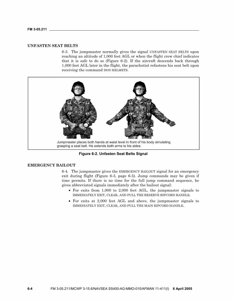
FM 3-05.211
6-4 FM 3-05.211/MCWP 3-15.6/NAVSEA SS400-AG-MMO-010/AFMAN 11-411(I) 6 April 2005
UNFASTEN SEAT BELTS 6-3. The jumpmaster normally gives the signal UNFASTEN SEAT BELTS upon reaching an altitude of 1,000 feet AGL or when the flight crew chief indicates that it is safe to do so (Figure 6-2). If the aircraft descends back through 1,000 feet AGL later in the flight, the parachutist refastens his seat belt upon receiving the command DON HELMETS.
Figure 6-2. Unfasten Seat Belts Signal
EMERGENCY BAILOUT 6-4. The jumpmaster gives the EMERGENCY BAILOUT signal for an emergency exit during flight (Figure 6-3, page 6-5). Jump commands may be given if time permits. If there is no time for the full jump command sequence, he gives abbreviated signals immediately after the bailout signal:
• For exits from 1,000 to 2,000 feet AGL, the jumpmaster signals to IMMEDIATELY EXIT, CLEAR, AND PULL THE RESERVE RIPCORD HANDLE.
• For exits at 2,000 feet AGL and above, the jumpmaster signals to IMMEDIATELY EXIT, CLEAR, AND PULL THE MAIN RIPCORD HANDLE.
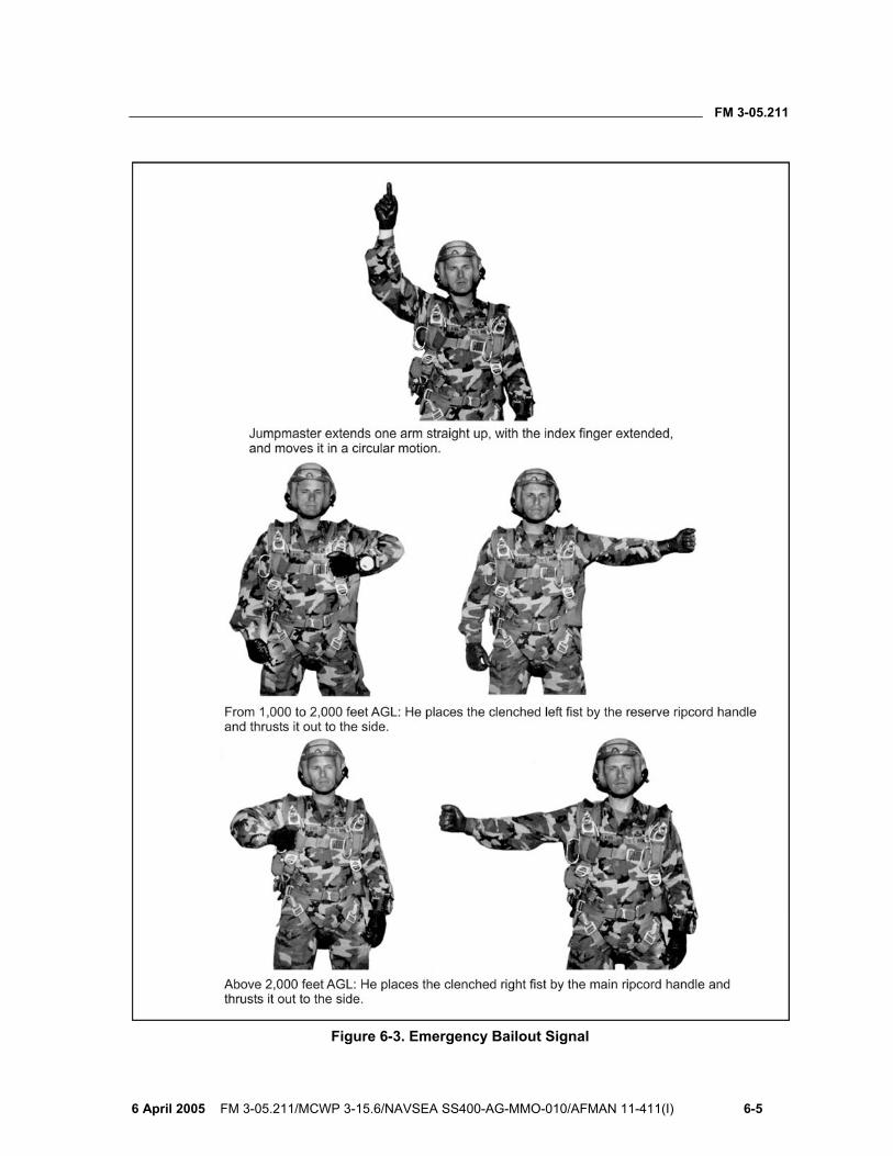
FM 3-05.211
6 April 2005 FM 3-05.211/MCWP 3-15.6/NAVSEA SS400-AG-MMO-010/AFMAN 11-411(I) 6-5
Figure 6-3. Emergency Bailout Signal
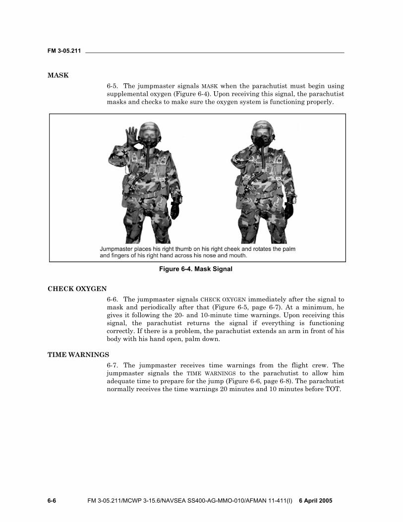
FM 3-05.211
6-6 FM 3-05.211/MCWP 3-15.6/NAVSEA SS400-AG-MMO-010/AFMAN 11-411(I) 6 April 2005
MASK 6-5. The jumpmaster signals MASK when the parachutist must begin using supplemental oxygen (Figure 6-4). Upon receiving this signal, the parachutist masks and checks to make sure the oxygen system is functioning properly.
Figure 6-4. Mask Signal
CHECK OXYGEN 6-6. The jumpmaster signals CHECK OXYGEN immediately after the signal to mask and periodically after that (Figure 6-5, page 6-7). At a minimum, he gives it following the 20- and 10-minute time warnings. Upon receiving this signal, the parachutist returns the signal if everything is functioning correctly. If there is a problem, the parachutist extends an arm in front of his body with his hand open, palm down.
TIME WARNINGS 6-7. The jumpmaster receives time warnings from the flight crew. The jumpmaster signals the TIME WARNINGS to the parachutist to allow him adequate time to prepare for the jump (Figure 6-6, page 6-8). The parachutist normally receives the time warnings 20 minutes and 10 minutes before TOT.
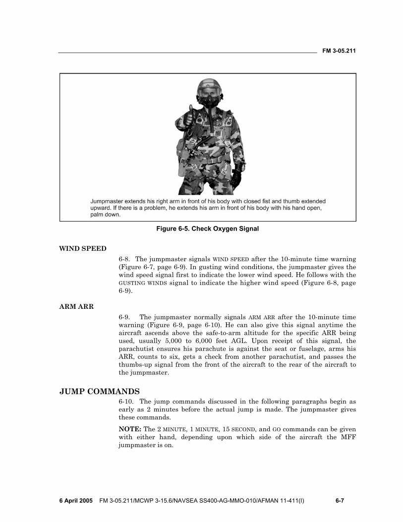
FM 3-05.211
6 April 2005 FM 3-05.211/MCWP 3-15.6/NAVSEA SS400-AG-MMO-010/AFMAN 11-411(I) 6-7
Figure 6-5. Check Oxygen Signal
WIND SPEED 6-8. The jumpmaster signals WIND SPEED after the 10-minute time warning (Figure 6-7, page 6-9). In gusting wind conditions, the jumpmaster gives the wind speed signal first to indicate the lower wind speed. He follows with the GUSTING WINDS signal to indicate the higher wind speed (Figure 6-8, page 6-9).
ARM ARR 6-9. The jumpmaster normally signals ARM ARR after the 10-minute time warning (Figure 6-9, page 6-10). He can also give this signal anytime the aircraft ascends above the safe-to-arm altitude for the specific ARR being used, usually 5,000 to 6,000 feet AGL. Upon receipt of this signal, the parachutist ensures his parachute is against the seat or fuselage, arms his ARR, counts to six, gets a check from another parachutist, and passes the thumbs-up signal from the front of the aircraft to the rear of the aircraft to the jumpmaster.
JUMP COMMANDS 6-10. The jump commands discussed in the following paragraphs begin as early as 2 minutes before the actual jump is made. The jumpmaster gives these commands.
NOTE: The 2 MINUTE, 1 MINUTE, 15 SECOND, and GO commands can be given with either hand, depending upon which side of the aircraft the MFF jumpmaster is on.
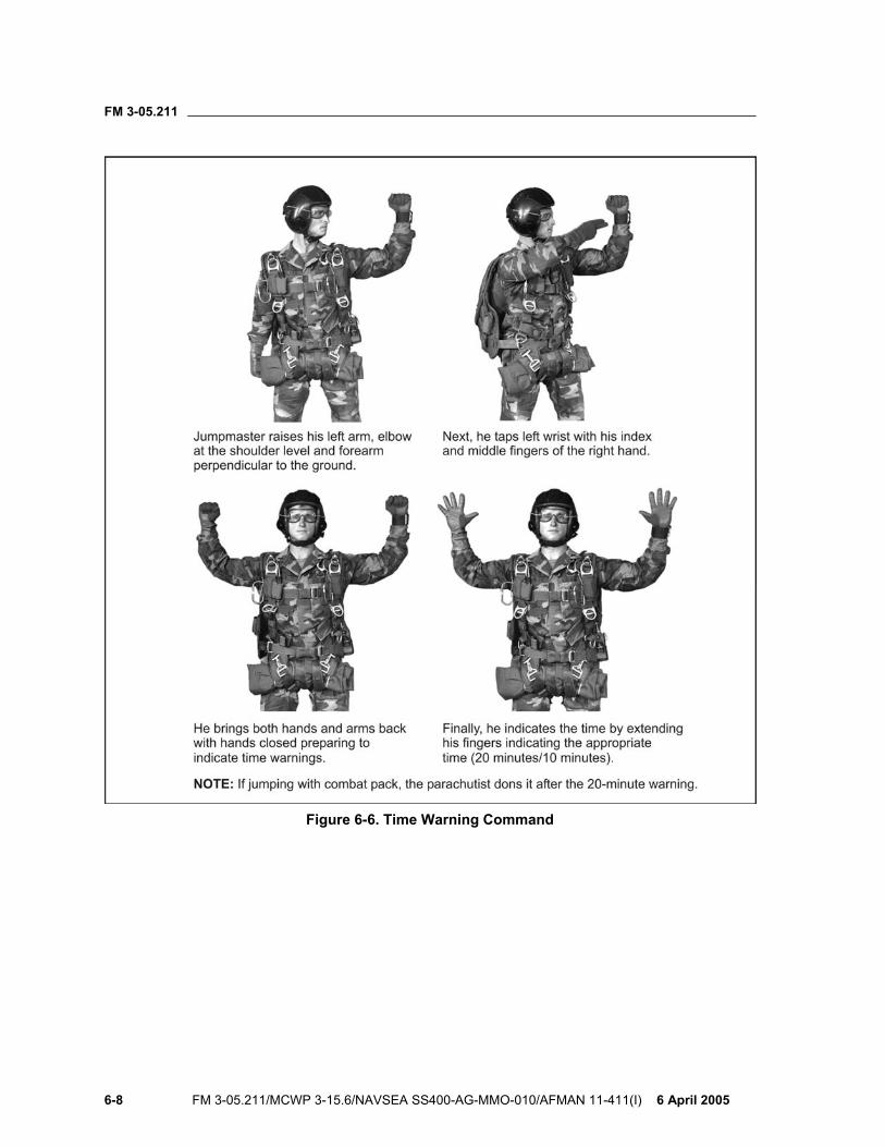
FM 3-05.211
6-8 FM 3-05.211/MCWP 3-15.6/NAVSEA SS400-AG-MMO-010/AFMAN 11-411(I) 6 April 2005
Figure 6-6. Time Warning Command
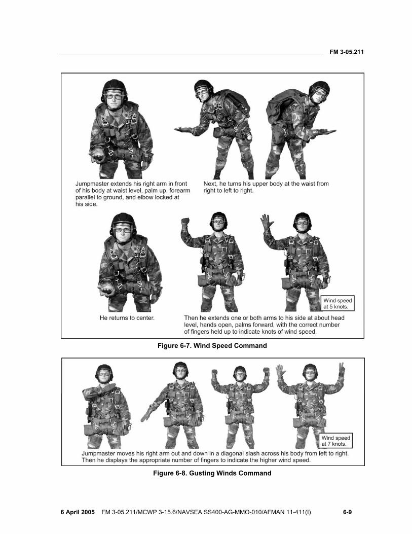
FM 3-05.211
6 April 2005 FM 3-05.211/MCWP 3-15.6/NAVSEA SS400-AG-MMO-010/AFMAN 11-411(I) 6-9
Figure 6-7. Wind Speed Command
Figure 6-8. Gusting Winds Command
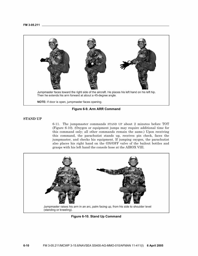
FM 3-05.211
6-10 FM 3-05.211/MCWP 3-15.6/NAVSEA SS400-AG-MMO-010/AFMAN 11-411(I) 6 April 2005
Figure 6-9. Arm ARR Command
STAND UP 6-11. The jumpmaster commands STAND UP about 2 minutes before TOT (Figure 6-10). (Oxygen or equipment jumps may require additional time for this command only; all other commands remain the same.) Upon receiving this command, the parachutist stands up, receives pin check, faces the jumpmaster, and checks his equipment. If jumping oxygen, the parachutist also places his right hand on the ON/OFF valve of the bailout bottles and grasps with his left hand the console hose at the AIROX VIII.
Figure 6-10. Stand Up Command
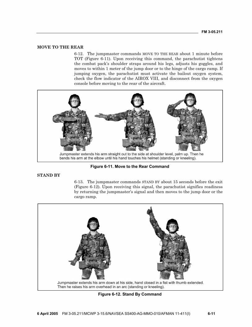
FM 3-05.211
6 April 2005 FM 3-05.211/MCWP 3-15.6/NAVSEA SS400-AG-MMO-010/AFMAN 11-411(I) 6-11
MOVE TO THE REAR 6-12. The jumpmaster commands MOVE TO THE REAR about 1 minute before TOT (Figure 6-11). Upon receiving this command, the parachutist tightens the combat pack’s shoulder straps around his legs, adjusts his goggles, and moves to within 1 meter of the jump door or to the hinge of the cargo ramp. If jumping oxygen, the parachutist must activate the bailout oxygen system, check the flow indicator of the AIROX VIII, and disconnect from the oxygen console before moving to the rear of the aircraft.
Figure 6-11. Move to the Rear Command
STAND BY 6-13. The jumpmaster commands STAND BY about 15 seconds before the exit (Figure 6-12). Upon receiving this signal, the parachutist signifies readiness by returning the jumpmaster’s signal and then moves to the jump door or the cargo ramp.
Figure 6-12. Stand By Command
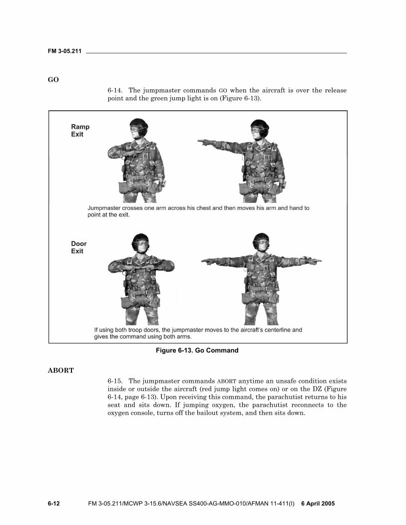
FM 3-05.211
6-12 FM 3-05.211/MCWP 3-15.6/NAVSEA SS400-AG-MMO-010/AFMAN 11-411(I) 6 April 2005
GO 6-14. The jumpmaster commands GO when the aircraft is over the release point and the green jump light is on (Figure 6-13).
Figure 6-13. Go Command
ABORT 6-15. The jumpmaster commands ABORT anytime an unsafe condition exists inside or outside the aircraft (red jump light comes on) or on the DZ (Figure 6-14, page 6-13). Upon receiving this command, the parachutist returns to his seat and sits down. If jumping oxygen, the parachutist reconnects to the oxygen console, turns off the bailout system, and then sits down.

FM 3-05.211
6 April 2005 FM 3-05.211/MCWP 3-15.6/NAVSEA SS400-AG-MMO-010/AFMAN 11-411(I) 6-13
Figure 6-14. Abort
DISARM ARR 6-16. The jumpmaster gives the signal DISARM ARR by reversing the ARM ARR signal. The assistant jumpmaster or jumpmaster checks the ARR to ensure it is correctly disarmed and then performs a pin check on the main and reserve parachutes. The parachutist on the right side of another parachutist can more easily reinsert the arming pin.
Caution If the jumpmaster has cocked his arm to give the command GO, he must NOT move it when he gives the abort signal. The parachutists may exit if the jumpmaster moves his cocked arm.

This page intentionally left blank.
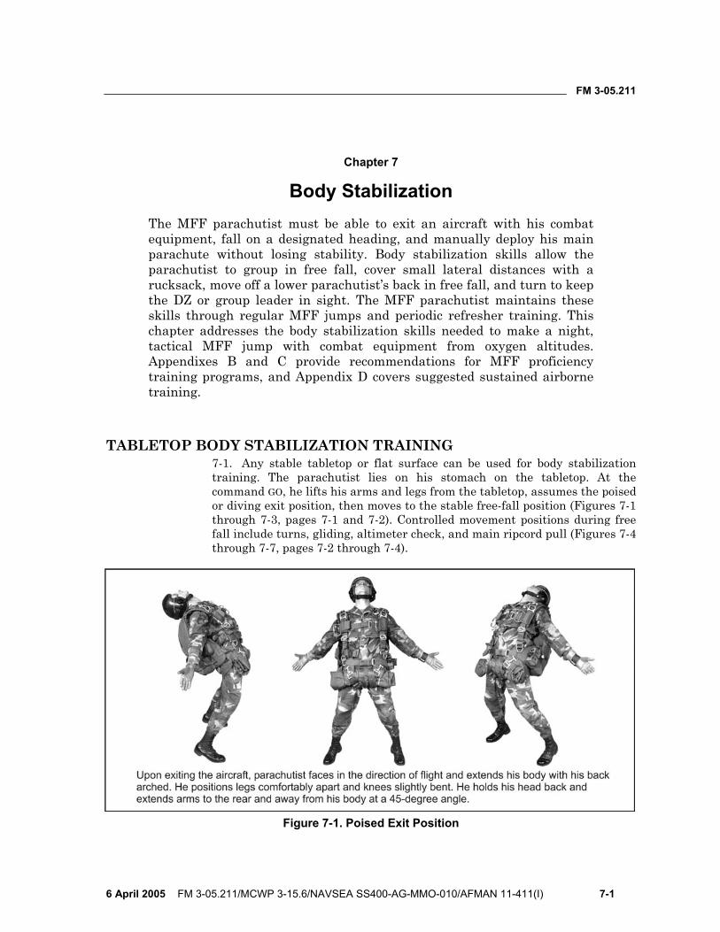
FM 3-05.211
6 April 2005 FM 3-05.211/MCWP 3-15.6/NAVSEA SS400-AG-MMO-010/AFMAN 11-411(I) 7-1
Chapter 7
Body Stabilization The MFF parachutist must be able to exit an aircraft with his combat equipment, fall on a designated heading, and manually deploy his main parachute without losing stability. Body stabilization skills allow the parachutist to group in free fall, cover small lateral distances with a rucksack, move off a lower parachutist’s back in free fall, and turn to keep the DZ or group leader in sight. The MFF parachutist maintains these skills through regular MFF jumps and periodic refresher training. This chapter addresses the body stabilization skills needed to make a night, tactical MFF jump with combat equipment from oxygen altitudes. Appendixes B and C provide recommendations for MFF proficiency training programs, and Appendix D covers suggested sustained airborne training.
TABLETOP BODY STABILIZATION TRAINING 7-1. Any stable tabletop or flat surface can be used for body stabilization training. The parachutist lies on his stomach on the tabletop. At the command GO, he lifts his arms and legs from the tabletop, assumes the poised or diving exit position, then moves to the stable free-fall position (Figures 7-1 through 7-3, pages 7-1 and 7-2). Controlled movement positions during free fall include turns, gliding, altimeter check, and main ripcord pull (Figures 7-4 through 7-7, pages 7-2 through 7-4).
Figure 7-1. Poised Exit Position
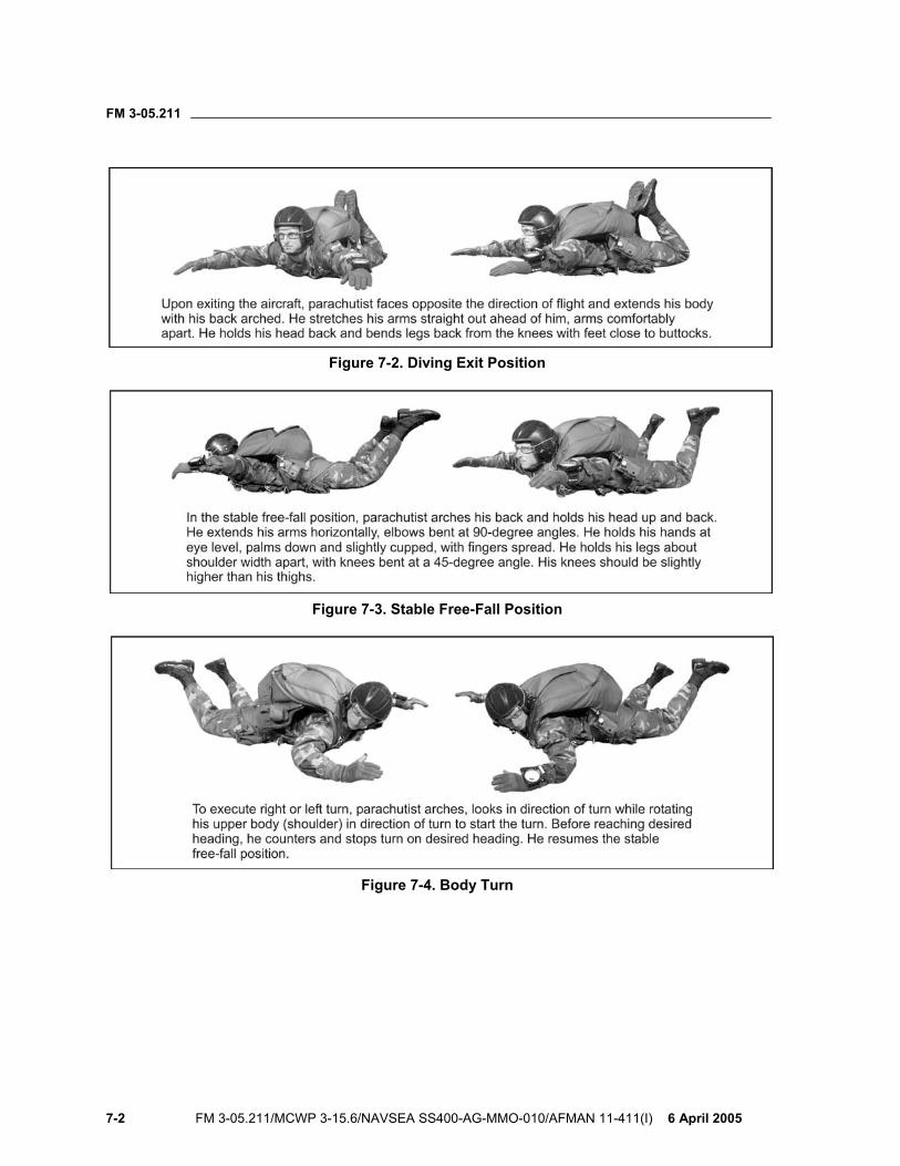
FM 3-05.211
7-2 FM 3-05.211/MCWP 3-15.6/NAVSEA SS400-AG-MMO-010/AFMAN 11-411(I) 6 April 2005
Figure 7-2. Diving Exit Position
Figure 7-3. Stable Free-Fall Position
Figure 7-4. Body Turn
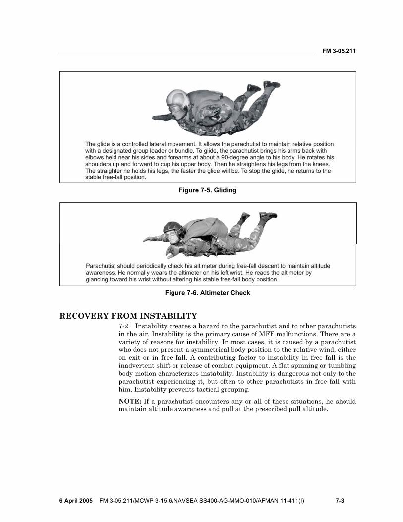
FM 3-05.211
6 April 2005 FM 3-05.211/MCWP 3-15.6/NAVSEA SS400-AG-MMO-010/AFMAN 11-411(I) 7-3
Figure 7-5. Gliding
Figure 7-6. Altimeter Check
RECOVERY FROM INSTABILITY 7-2. Instability creates a hazard to the parachutist and to other parachutists in the air. Instability is the primary cause of MFF malfunctions. There are a variety of reasons for instability. In most cases, it is caused by a parachutist who does not present a symmetrical body position to the relative wind, either on exit or in free fall. A contributing factor to instability in free fall is the inadvertent shift or release of combat equipment. A flat spinning or tumbling body motion characterizes instability. Instability is dangerous not only to the parachutist experiencing it, but often to other parachutists in free fall with him. Instability prevents tactical grouping.
NOTE: If a parachutist encounters any or all of these situations, he should maintain altitude awareness and pull at the prescribed pull altitude.
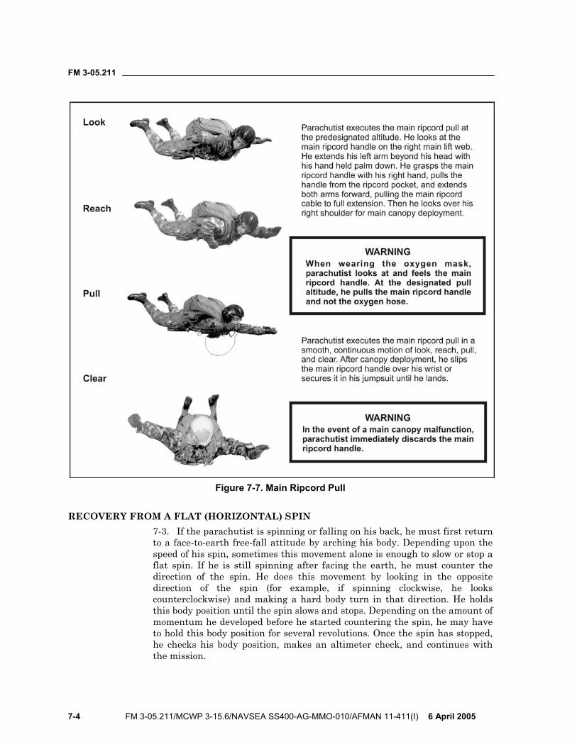
FM 3-05.211
7-4 FM 3-05.211/MCWP 3-15.6/NAVSEA SS400-AG-MMO-010/AFMAN 11-411(I) 6 April 2005
Figure 7-7. Main Ripcord Pull
RECOVERY FROM A FLAT (HORIZONTAL) SPIN 7-3. If the parachutist is spinning or falling on his back, he must first return to a face-to-earth free-fall attitude by arching his body. Depending upon the speed of his spin, sometimes this movement alone is enough to slow or stop a flat spin. If he is still spinning after facing the earth, he must counter the direction of the spin. He does this movement by looking in the opposite direction of the spin (for example, if spinning clockwise, he looks counterclockwise) and making a hard body turn in that direction. He holds this body position until the spin slows and stops. Depending on the amount of momentum he developed before he started countering the spin, he may have to hold this body position for several revolutions. Once the spin has stopped, he checks his body position, makes an altimeter check, and continues with the mission.
FM 3-05.211
6 April 2005 FM 3-05.211/MCWP 3-15.6/NAVSEA SS400-AG-MMO-010/AFMAN 11-411(I) 7-5
7-4. If a shift of the combat pack causes a flat spin, the parachutist may have to adjust his body position to obtain stability or maintain a heading. The severity of the shift (versus an inadvertent release) determines how much adjustment of the knees, the angle of the lower leg, hand and arm placement, or cocking of the hips he must make to counter the effect of a combat pack that is now not symmetrical or square to the relative wind.
RECOVERY FROM TUMBLING 7-5. A bump during a group exit or breaking the arched body position normally causes tumbling. If tumbling, the parachutist assumes the hard arch body position until facing the earth. Then, he relaxes the hard arch and assumes a stable free-fall body position. The time it takes to return to a face-to-earth position will vary with the severity of the tumble, the body area surface, and the parachutist’s combat equipment configuration. Presenting a symmetrical body position to the relative wind on exit from the aircraft is the most significant factor in preventing tumbling.
ALTITUDE AWARENESS 7-6. A parachutist who is unstable must remain altitude-aware. The stress created by instability can cause a normal human phenomenon of temporal (time) distortion. The resultant effect varies from individual to individual. It can appear to be either time compression or a slowing down of perceived time passage. He must not get so caught up in his attempts to recover stability that he loses altitude awareness and forgets to manually activate his parachute. He must never sacrifice the pull altitude for stability or the continued attempts to obtain stability before the pull. An unstable parachutist must remember that as he is falling, an area of low pressure is created above him. Any altimeter reading while in this low-pressure area will not reflect the correct altitude AGL. An example is a parachutist falling back to earth who looks at his altimeter while holding it in front of his face. Due to the low-pressure zone in which the altimeter is located, the parachutist will read a higher altitude than where he actually is in feet AGL.
NOTE: Parachutists must remember that this pressure differential can cause the altimeter to be off as much as 1,000 feet.
CORRECTIVE ACTIONS DURING FREE FALL 7-7. These actions are movements used to get off of a fellow parachutist’s back. Primary movements include—
• Left or right turns into a safe direction. • Forward glides (elbows into lazy “W,” legs extended) to clear airspace. • Side slides left or right. NOTE: A modification to a forward glide is the high-lift track. Only experienced HALO-qualified parachutists can use this technique, and only qualified MFF instructors will train parachutists on this technique.

This page intentionally left blank.
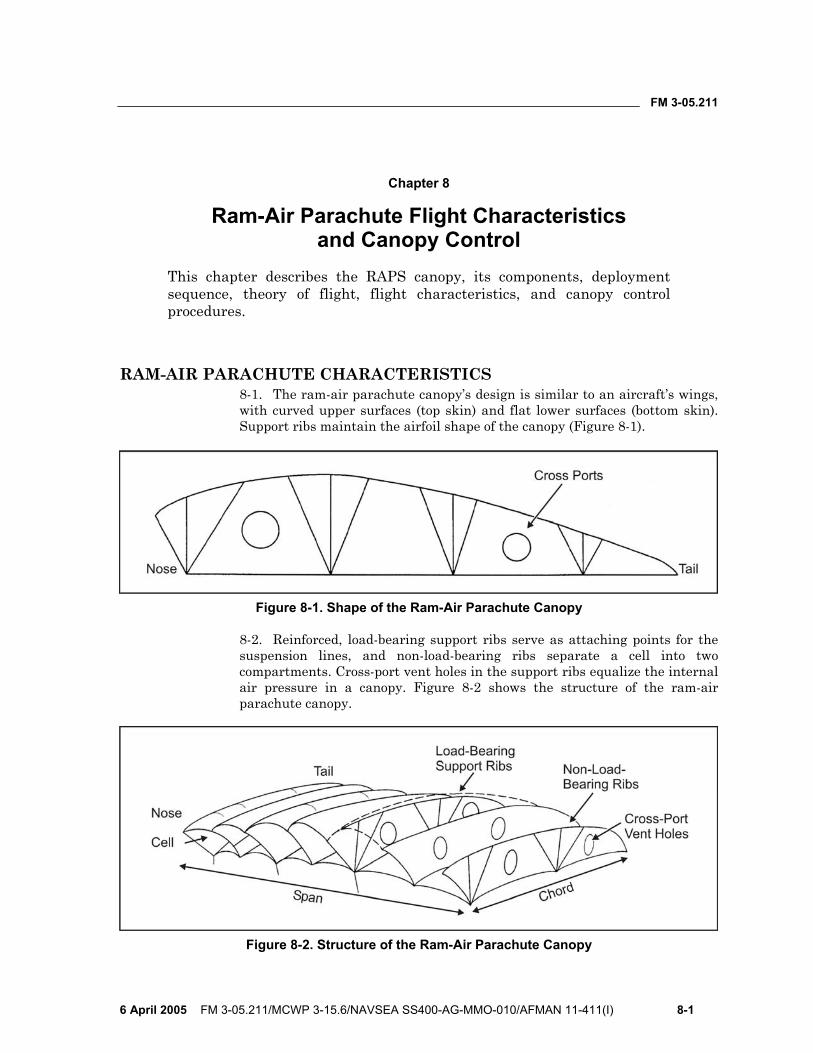
FM 3-05.211
6 April 2005 FM 3-05.211/MCWP 3-15.6/NAVSEA SS400-AG-MMO-010/AFMAN 11-411(I) 8-1
Chapter 8
Ram-Air Parachute Flight Characteristics and Canopy Control
This chapter describes the RAPS canopy, its components, deployment sequence, theory of flight, flight characteristics, and canopy control procedures.
RAM-AIR PARACHUTE CHARACTERISTICS 8-1. The ram-air parachute canopy’s design is similar to an aircraft’s wings, with curved upper surfaces (top skin) and flat lower surfaces (bottom skin). Support ribs maintain the airfoil shape of the canopy (Figure 8-1).
Figure 8-1. Shape of the Ram-Air Parachute Canopy
8-2. Reinforced, load-bearing support ribs serve as attaching points for the suspension lines, and non-load-bearing ribs separate a cell into two compartments. Cross-port vent holes in the support ribs equalize the internal air pressure in a canopy. Figure 8-2 shows the structure of the ram-air parachute canopy.
Figure 8-2. Structure of the Ram-Air Parachute Canopy

FM 3-05.211
8-2 FM 3-05.211/MCWP 3-15.6/NAVSEA SS400-AG-MMO-010/AFMAN 11-411(I) 6 April 2005
8-3. Nose, tail, chord, and span are terms of reference applied to ram-air parachutes. The open portion at the front is called the nose, with the rear being the tail. The distance from left to right is the span, and from nose to tail is the chord. Figure 8-3 shows the components of the ram-air parachute.
Figure 8-3. Components and Nomenclature of the Ram-Air Parachute
8-4. The stabilizers are single-layered extensions of the canopy on the left and right sides of the parachute. The stabilizers channel the airflow across the chord and help to maintain straight and stable flight.
8-5. The military ram-air canopy has four suspension line groups. They are identified from nose to tail as A, B, C, and D. A continuous line group is a line attached to the parachute’s bottom skin that runs directly to the connector link without having another line attached to it. The suspension lines distribute a suspended load under the canopy without distorting the canopy’s airfoil shape. Figure 8-4, page 8-3, shows the location of the ram-air parachute components. 8-6. Upper control lines converge from points of attachment on the left and right trailing edges of the tail, respectively, to common connection points with the lower control lines. The lower control lines are attached to the upper control lines and have a soft steering toggle secured to the lower end. Deployment brake loops sewn into the lower control lines set the canopy brakes for deployment. Figure 8-5, page 8-4, shows the components of the lower portion of the ram-air parachute. 8-7. The sail slider is a rectangular piece of reinforced fabric with a large grommet in each corner. The sail slider is a deployment device that retards the opening of a ram-air parachute.
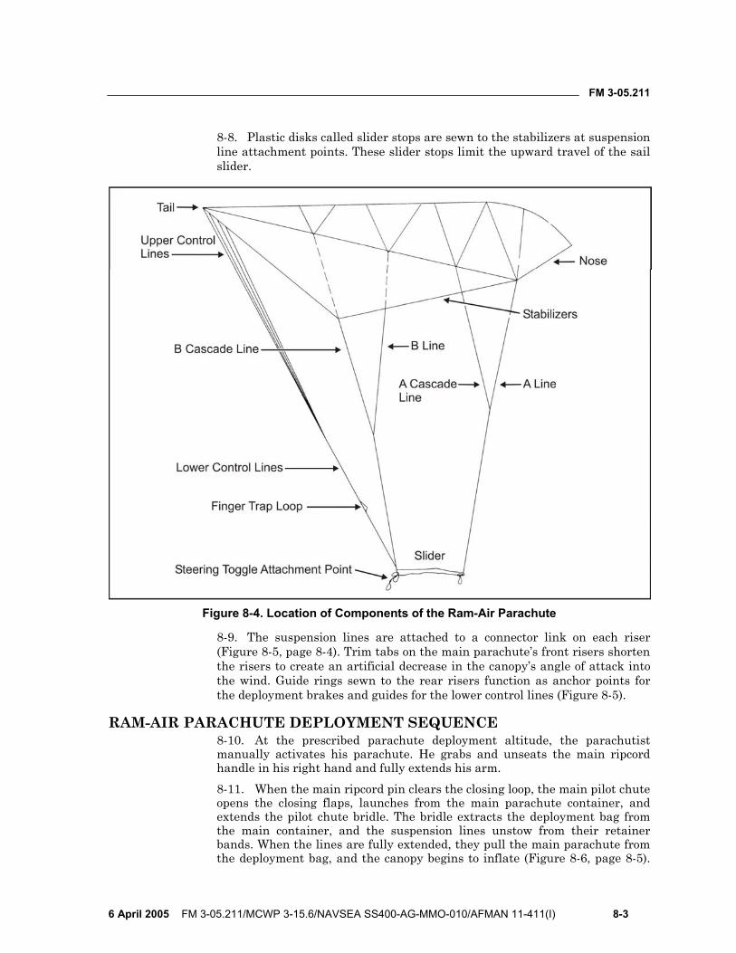
FM 3-05.211
6 April 2005 FM 3-05.211/MCWP 3-15.6/NAVSEA SS400-AG-MMO-010/AFMAN 11-411(I) 8-3
8-8. Plastic disks called slider stops are sewn to the stabilizers at suspension line attachment points. These slider stops limit the upward travel of the sail slider.
Figure 8-4. Location of Components of the Ram-Air Parachute
8-9. The suspension lines are attached to a connector link on each riser (Figure 8-5, page 8-4). Trim tabs on the main parachute’s front risers shorten the risers to create an artificial decrease in the canopy’s angle of attack into the wind. Guide rings sewn to the rear risers function as anchor points for the deployment brakes and guides for the lower control lines (Figure 8-5).
RAM-AIR PARACHUTE DEPLOYMENT SEQUENCE 8-10. At the prescribed parachute deployment altitude, the parachutist manually activates his parachute. He grabs and unseats the main ripcord handle in his right hand and fully extends his arm. 8-11. When the main ripcord pin clears the closing loop, the main pilot chute opens the closing flaps, launches from the main parachute container, and extends the pilot chute bridle. The bridle extracts the deployment bag from the main container, and the suspension lines unstow from their retainer bands. When the lines are fully extended, they pull the main parachute from the deployment bag, and the canopy begins to inflate (Figure 8-6, page 8-5).
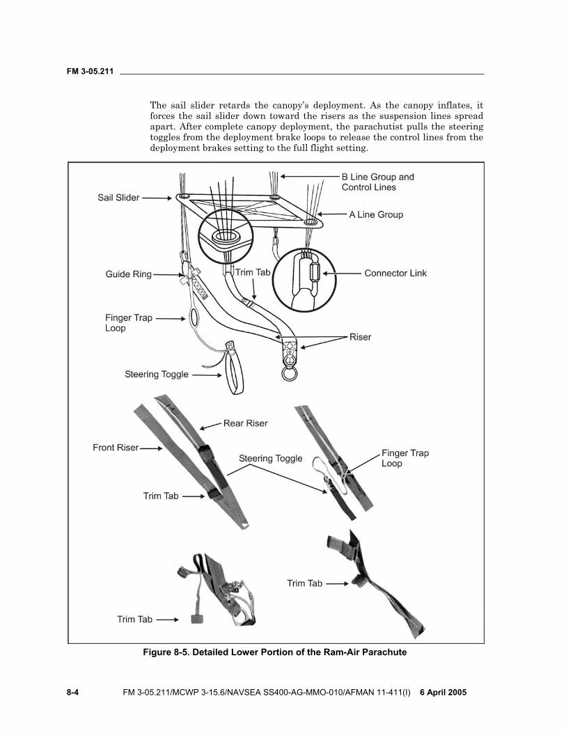
FM 3-05.211
8-4 FM 3-05.211/MCWP 3-15.6/NAVSEA SS400-AG-MMO-010/AFMAN 11-411(I) 6 April 2005
The sail slider retards the canopy’s deployment. As the canopy inflates, it forces the sail slider down toward the risers as the suspension lines spread apart. After complete canopy deployment, the parachutist pulls the steering toggles from the deployment brake loops to release the control lines from the deployment brakes setting to the full flight setting.
Figure 8-5. Detailed Lower Portion of the Ram-Air Parachute
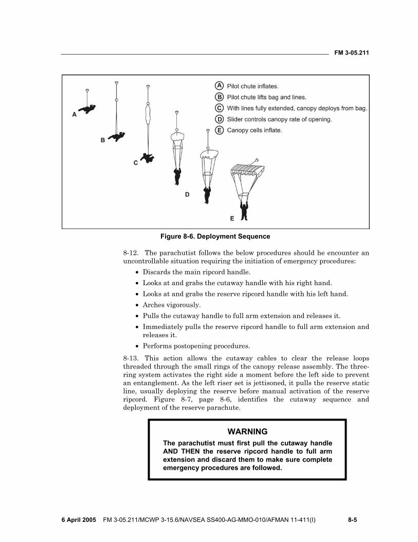
FM 3-05.211
6 April 2005 FM 3-05.211/MCWP 3-15.6/NAVSEA SS400-AG-MMO-010/AFMAN 11-411(I) 8-5
Figure 8-6. Deployment Sequence
8-12. The parachutist follows the below procedures should he encounter an uncontrollable situation requiring the initiation of emergency procedures:
• Discards the main ripcord handle. • Looks at and grabs the cutaway handle with his right hand. • Looks at and grabs the reserve ripcord handle with his left hand. • Arches vigorously. • Pulls the cutaway handle to full arm extension and releases it. • Immediately pulls the reserve ripcord handle to full arm extension and
releases it. • Performs postopening procedures.
8-13. This action allows the cutaway cables to clear the release loops threaded through the small rings of the canopy release assembly. The three-ring system activates the right side a moment before the left side to prevent an entanglement. As the left riser set is jettisoned, it pulls the reserve static line, usually deploying the reserve before manual activation of the reserve ripcord. Figure 8-7, page 8-6, identifies the cutaway sequence and deployment of the reserve parachute.
WARNING The parachutist must first pull the cutaway handle AND THEN the reserve ripcord handle to full arm extension and discard them to make sure complete emergency procedures are followed.

FM 3-05.211
8-6 FM 3-05.211/MCWP 3-15.6/NAVSEA SS400-AG-MMO-010/AFMAN 11-411(I) 6 April 2005
Figure 8-7. Cutaway Sequence and Deployment of the Reserve Parachute
8-14. As the reserve ripcord pins clear the closing loops, the pilot chute opens the closing flaps. The pilot chute deploys from the reserve parachute container and, as it catches air, extends the 2-inch-wide high-drag bridle. Upon extraction of the reserve free bag from the container, the free-stowed suspension lines deploy from a pocket on the free bag and extract the reserve

FM 3-05.211
6 April 2005 FM 3-05.211/MCWP 3-15.6/NAVSEA SS400-AG-MMO-010/AFMAN 11-411(I) 8-7
parachute from the free bag. The free bag then completely separates from the reserve parachute. As the canopy deploys, it forces the sail slider down the suspension lines. When the parachutist releases the toggles from the deployment brake loops, he releases the control lines from the deployment brake setting to the full flight setting.
RAM-AIR PARACHUTE THEORY OF FLIGHT 8-15. The ram-air parachute is an inflated and pressurized fabric airfoil that generates lift by moving forward through the air. The relative lengths of the suspension lines maintain the airfoil’s angle of attack. In flight, the parachutist keeps the wing’s leading edge at a slightly lower angle than the trailing edge. Thus, this angle forces the canopy’s airfoil-shaped surface to glide or plane through the air, very much like a glider in descending flight. The wing-shaped ram-air parachute generates lift caused by the reduced pressure of the airflow over the curved upper surface.
8-16. The ram-air parachute’s leading edge is open or physically missing, forming intakes that allow the cells to be ram-air inflated. Internal air pressure pushes a small amount of stagnant air ahead of the airfoil, forming an artificial leading edge. The focal point of this stagnant air acts as a true leading edge, deflecting the relative air above and below. Drag is the only force that retards the wing’s forward motion through the air. Drag is created by the friction of air passing over the canopy fabric, the suspension lines, and the parachutist and his equipment. Gravity, plus the resultant sum of these aerodynamic forces on the upper surface, acts to pull the ram-air parachute through the air and contributes to the flat glide angle of the canopy (Figure 8-8).
Figure 8-8. Ram-Air Parachute Theory of Flight
8-17. Applying brakes on the ram-air parachute causes the trailing edge to deflect downward, creating additional drag (Figure 8-9, page 8-8). This drag produces a proportionate loss of airspeed but generates lift for a short time.
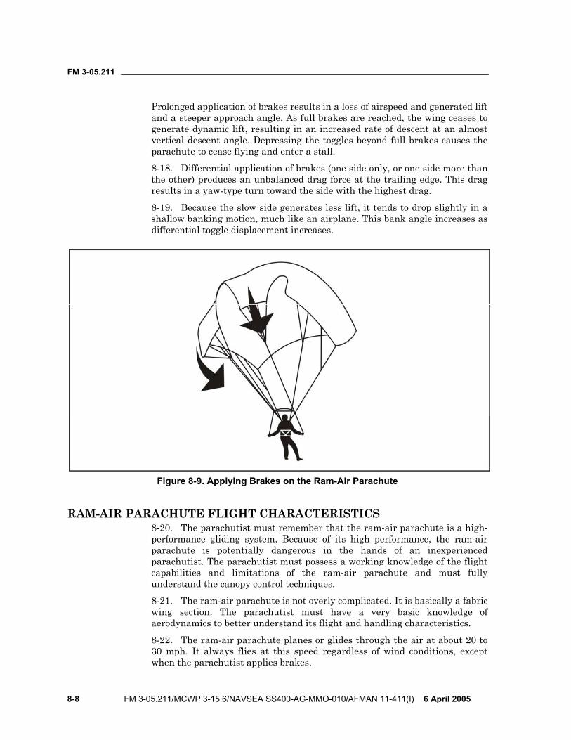
FM 3-05.211
8-8 FM 3-05.211/MCWP 3-15.6/NAVSEA SS400-AG-MMO-010/AFMAN 11-411(I) 6 April 2005
Prolonged application of brakes results in a loss of airspeed and generated lift and a steeper approach angle. As full brakes are reached, the wing ceases to generate dynamic lift, resulting in an increased rate of descent at an almost vertical descent angle. Depressing the toggles beyond full brakes causes the parachute to cease flying and enter a stall.
8-18. Differential application of brakes (one side only, or one side more than the other) produces an unbalanced drag force at the trailing edge. This drag results in a yaw-type turn toward the side with the highest drag.
8-19. Because the slow side generates less lift, it tends to drop slightly in a shallow banking motion, much like an airplane. This bank angle increases as differential toggle displacement increases.
Figure 8-9. Applying Brakes on the Ram-Air Parachute
RAM-AIR PARACHUTE FLIGHT CHARACTERISTICS 8-20. The parachutist must remember that the ram-air parachute is a high-performance gliding system. Because of its high performance, the ram-air parachute is potentially dangerous in the hands of an inexperienced parachutist. The parachutist must possess a working knowledge of the flight capabilities and limitations of the ram-air parachute and must fully understand the canopy control techniques.
8-21. The ram-air parachute is not overly complicated. It is basically a fabric wing section. The parachutist must have a very basic knowledge of aerodynamics to better understand its flight and handling characteristics.
8-22. The ram-air parachute planes or glides through the air at about 20 to 30 mph. It always flies at this speed regardless of wind conditions, except when the parachutist applies brakes.

FM 3-05.211
6 April 2005 FM 3-05.211/MCWP 3-15.6/NAVSEA SS400-AG-MMO-010/AFMAN 11-411(I) 8-9
8-23. The flying speed is called airspeed and remains constant regardless of whether the parachute is headed upwind, downwind, or crosswind. The only variation in flying upwind or downwind is a change in ground speed that is often mistaken for a change in airspeed.
8-24. Wind affects ground speed only and has no effect on airspeed. Brakes applied with conventional control lines and toggles control the ram-air parachute’s airspeed. Fifty percent of toggle travel on a ram-air parachute will cause a speed reduction of close to 12 mph.
8-25. There is almost no surge on deployment, and there is no wind noise at all until after releasing the brakes. A parachutist who has not been previously exposed to the ram-air parachute’s flight characteristics can use the wind noise created by forward speed as a rough airspeed indicator. A reduction in the wind noise level can provide a stall warning.
8-26. After the parachutist becomes accustomed to the canopy, he may fail to notice the wind noise. By this time he should have learned to fly the canopy by feel, and he should notice the stall warning point and determine this point at altitude under his canopy controllability check. The parachutist will feel the canopy shudder as it loses lift and begins to stall. The parachutist should remember that angle of attack, cross wind, and wind turbulence can increase the stall point without warning.
8-27. The parachutist must remember that, in controlling the canopy’s flight, how fast he moves the toggles from one position to another is as critical as the relative position of the toggles. As a rule, rapid and generous (more than 30 percent) application of both toggles will cause a rapid decrease in airspeed, decelerating into the stall range at about 0 to 3 mph. (Depending on the wind speed, the ground speed could still be very high.)
8-28. Due to the penetrating ability of the ram-air parachute, parachutists often find it difficult to determine wind direction without the aid of a windsock, streamer, or smoke on the ground. All landings should be made facing into the wind.
8-29. The ram-air parachute has a constant airspeed of 20 to 30 mph. If the parachutist points the ram-air parachute downwind with a 10-mph wind, the ground speed will be 30 to 40 mph. If he turns the ram-air parachute into the wind and the winds are 10 mph, the airspeed remains the same but the ground speed reduces by 10 mph. If the ram-air parachute faces into 20-mph winds, the ground speed will be 0 mph (Figure 8-10, page 8-10).
CANOPY CONTROL 8-30. The overall objective of MFF parachuting is to land personnel and equipment intact to accomplish the assigned mission. The free-fall parachutist must know and employ the principles of canopy control as they relate to the use of the ram-air parachute.
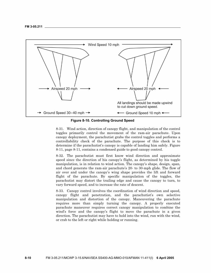
FM 3-05.211
8-10 FM 3-05.211/MCWP 3-15.6/NAVSEA SS400-AG-MMO-010/AFMAN 11-411(I) 6 April 2005
Figure 8-10. Controlling Ground Speed
8-31. Wind action, direction of canopy flight, and manipulation of the control toggles primarily control the movement of the ram-air parachute. Upon canopy deployment, the parachutist grabs the control toggles and performs a controllability check of the parachute. The purpose of this check is to determine if the parachutist’s canopy is capable of landing him safely. Figure 8-11, page 8-11, contains a condensed guide to good canopy control.
8-32. The parachutist must first know wind direction and approximate speed since the direction of his canopy’s flight, as determined by his toggle manipulation, is in relation to wind action. The canopy’s shape, design, span, and chord generate the ram-air parachute’s 20- to 30-mph glide. The flow of air over and under the canopy’s wing shape provides the lift and forward flight of the parachute. By specific manipulation of the toggles, the parachutist may distort the trailing edge and cause the canopy to turn, to vary forward speed, and to increase the rate of descent.
8-33. Canopy control involves the coordination of wind direction and speed, canopy flight and penetration, and the parachutist’s own selective manipulation and distortion of the canopy. Maneuvering the parachute requires more than simply turning the canopy. A properly executed parachute maneuver requires correct canopy manipulation to combine the wind’s force and the canopy’s flight to move the parachute in a given direction. The parachutist may have to hold into the wind, run with the wind, or crab to the left or right while holding or running.
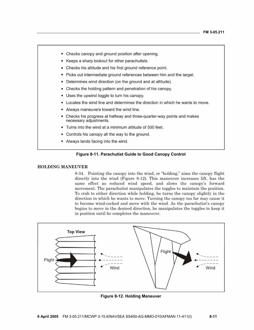
FM 3-05.211
6 April 2005 FM 3-05.211/MCWP 3-15.6/NAVSEA SS400-AG-MMO-010/AFMAN 11-411(I) 8-11
Figure 8-11. Parachutist Guide to Good Canopy Control
HOLDING MANEUVER 8-34. Pointing the canopy into the wind, or “holding,” aims the canopy flight directly into the wind (Figure 8-12). This maneuver increases lift, has the same effect as reduced wind speed, and slows the canopy’s forward movement. The parachutist manipulates the toggles to maintain the position. To crab to either direction while holding, he turns the canopy slightly in the direction in which he wants to move. Turning the canopy too far may cause it to become wind-cocked and move with the wind. As the parachutist’s canopy begins to move in the desired direction, he manipulates the toggles to keep it in position until he completes the maneuver.
Figure 8-12. Holding Maneuver
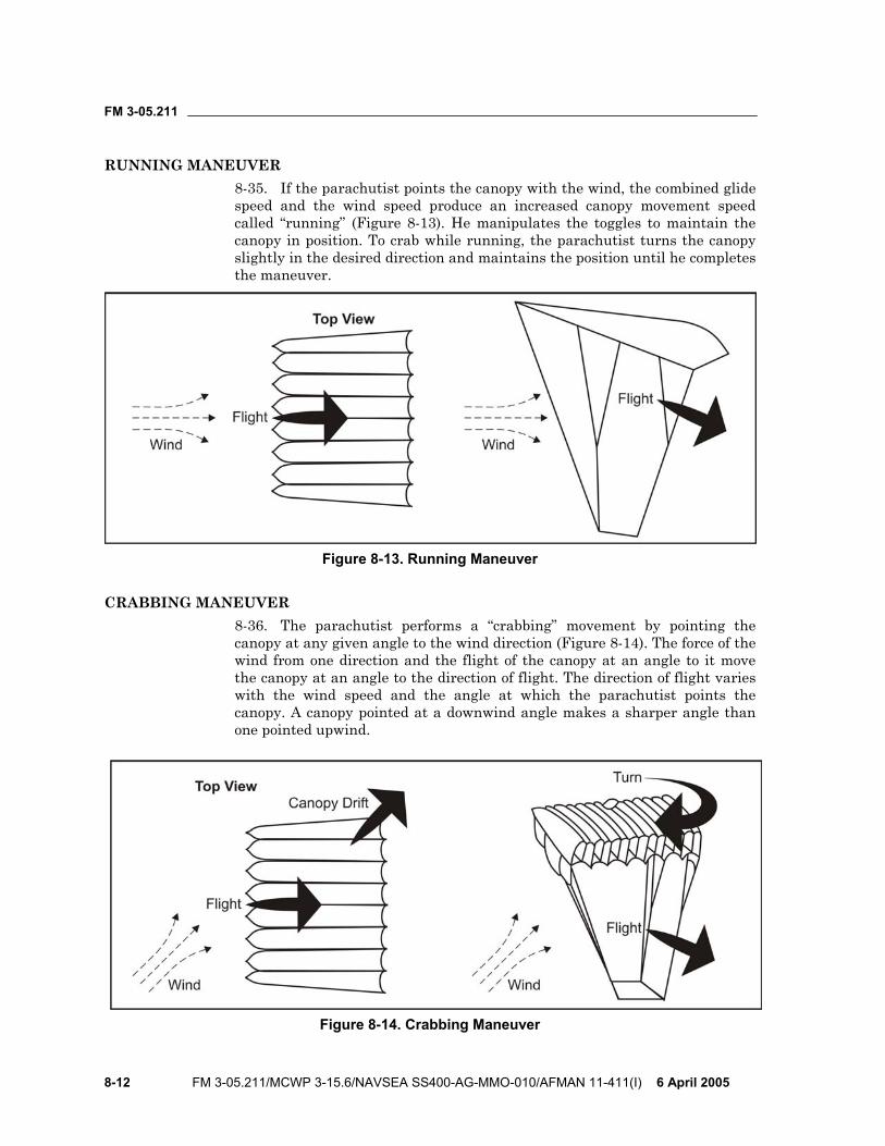
FM 3-05.211
8-12 FM 3-05.211/MCWP 3-15.6/NAVSEA SS400-AG-MMO-010/AFMAN 11-411(I) 6 April 2005
RUNNING MANEUVER 8-35. If the parachutist points the canopy with the wind, the combined glide speed and the wind speed produce an increased canopy movement speed called “running” (Figure 8-13). He manipulates the toggles to maintain the canopy in position. To crab while running, the parachutist turns the canopy slightly in the desired direction and maintains the position until he completes the maneuver.
Figure 8-13. Running Maneuver
CRABBING MANEUVER 8-36. The parachutist performs a “crabbing” movement by pointing the canopy at any given angle to the wind direction (Figure 8-14). The force of the wind from one direction and the flight of the canopy at an angle to it move the canopy at an angle to the direction of flight. The direction of flight varies with the wind speed and the angle at which the parachutist points the canopy. A canopy pointed at a downwind angle makes a sharper angle than one pointed upwind.
Figure 8-14. Crabbing Maneuver
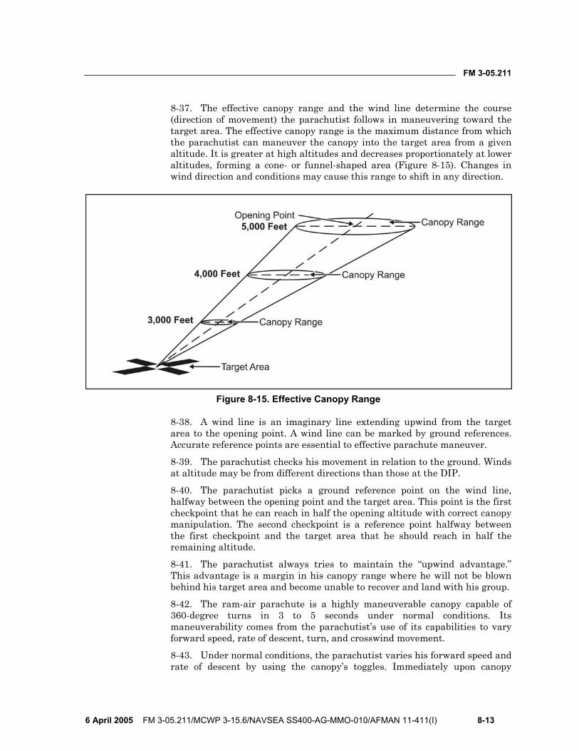
FM 3-05.211
6 April 2005 FM 3-05.211/MCWP 3-15.6/NAVSEA SS400-AG-MMO-010/AFMAN 11-411(I) 8-13
8-37. The effective canopy range and the wind line determine the course (direction of movement) the parachutist follows in maneuvering toward the target area. The effective canopy range is the maximum distance from which the parachutist can maneuver the canopy into the target area from a given altitude. It is greater at high altitudes and decreases proportionately at lower altitudes, forming a cone- or funnel-shaped area (Figure 8-15). Changes in wind direction and conditions may cause this range to shift in any direction.
Figure 8-15. Effective Canopy Range
8-38. A wind line is an imaginary line extending upwind from the target area to the opening point. A wind line can be marked by ground references. Accurate reference points are essential to effective parachute maneuver.
8-39. The parachutist checks his movement in relation to the ground. Winds at altitude may be from different directions than those at the DIP.
8-40. The parachutist picks a ground reference point on the wind line, halfway between the opening point and the target area. This point is the first checkpoint that he can reach in half the opening altitude with correct canopy manipulation. The second checkpoint is a reference point halfway between the first checkpoint and the target area that he should reach in half the remaining altitude.
8-41. The parachutist always tries to maintain the “upwind advantage.” This advantage is a margin in his canopy range where he will not be blown behind his target area and become unable to recover and land with his group.
8-42. The ram-air parachute is a highly maneuverable canopy capable of 360-degree turns in 3 to 5 seconds under normal conditions. Its maneuverability comes from the parachutist’s use of its capabilities to vary forward speed, rate of descent, turn, and crosswind movement.
8-43. Under normal conditions, the parachutist varies his forward speed and rate of descent by using the canopy’s toggles. Immediately upon canopy

FM 3-05.211
8-14 FM 3-05.211/MCWP 3-15.6/NAVSEA SS400-AG-MMO-010/AFMAN 11-411(I) 6 April 2005
deployment, he clears the toggles from the deployment brakes setting and performs a controllability check. His toggle position at the stall point will be at a different position as wind speed increases and when carrying heavy equipment loads.
WARNING Before attempting any maneuvers or turns, the parachutist must be alert to prevent collisions with other parachutists. This maneuver is especially critical below 500 feet AGL.
FULL FLIGHT (NO BRAKES) 8-44. The maximum canopy flight and penetration for maneuvering are obtained using full flight. The toggles are in the up position behind the rear risers (Figure 8-16).
Figure 8-16. Full Flight
HALF BRAKES 8-45. The parachutist grasps the toggles and pulls them down to about shoulder or chest level for the half-brakes position (Figure 8-17, page 8-15). The canopy speed will decrease to about a 9- to 12-mph flight, and the rate of descent will increase.
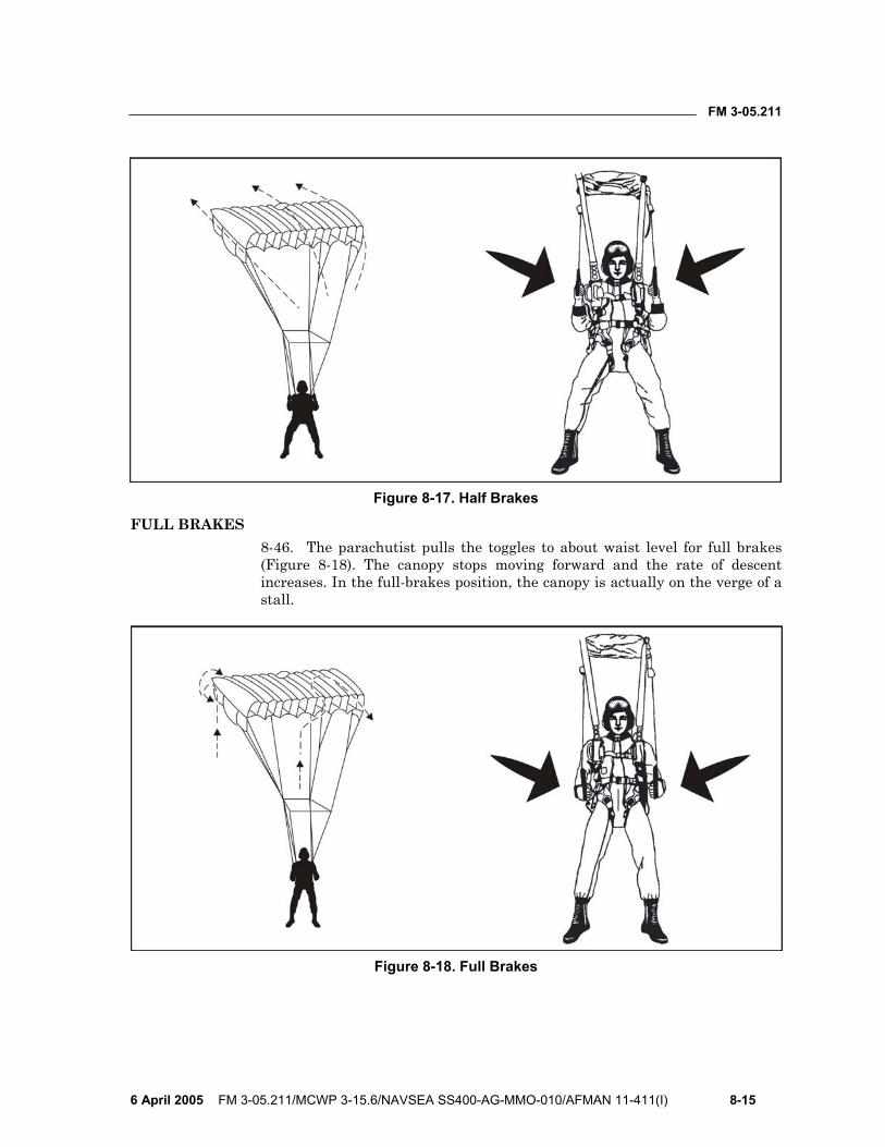
FM 3-05.211
6 April 2005 FM 3-05.211/MCWP 3-15.6/NAVSEA SS400-AG-MMO-010/AFMAN 11-411(I) 8-15
Figure 8-17. Half Brakes
FULL BRAKES 8-46. The parachutist pulls the toggles to about waist level for full brakes (Figure 8-18). The canopy stops moving forward and the rate of descent increases. In the full-brakes position, the canopy is actually on the verge of a stall.
Figure 8-18. Full Brakes
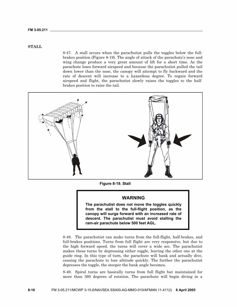
FM 3-05.211
8-16 FM 3-05.211/MCWP 3-15.6/NAVSEA SS400-AG-MMO-010/AFMAN 11-411(I) 6 April 2005
STALL 8-47. A stall occurs when the parachutist pulls the toggles below the full-brakes position (Figure 8-19). The angle of attack of the parachute’s nose and wing change produce a very great amount of lift for a short time. As the parachute loses forward airspeed and because the parachutist pulled the tail down lower than the nose, the canopy will attempt to fly backward and the rate of descent will increase to a hazardous degree. To regain forward airspeed and flight, the parachutist slowly raises the toggles to the half-brakes position to raise the tail.
Figure 8-19. Stall
WARNING The parachutist does not move the toggles quickly from the stall to the full-flight position, as the canopy will surge forward with an increased rate of descent. The parachutist must avoid stalling the ram-air parachute below 500 feet AGL.
8-48. The parachutist can make turns from the full-flight, half-brakes, and full-brakes positions. Turns from full flight are very responsive, but due to the high forward speed, the turns will cover a wide arc. The parachutist makes these turns by depressing either toggle, leaving the other one at the guide ring. In this type of turn, the parachute will bank and actually dive, causing the parachute to lose altitude quickly. The further the parachutist depresses the toggle, the steeper the bank angle becomes.
8-49. Spiral turns are basically turns from full flight but maintained for more than 360 degrees of rotation. The parachute will begin diving in a
FM 3-05.211
6 April 2005 FM 3-05.211/MCWP 3-15.6/NAVSEA SS400-AG-MMO-010/AFMAN 11-411(I) 8-17
spiral. The first turn will be fairly slow, with shallow bank angles, but the turn speed and bank angle will increase rapidly while the parachutist maintains the spiral.
NOTE: The parachutist should use trim tabs located on the front risers to lose altitude, if required. During HAHO operation jumps, the trim tabs can be used to make minor corrections to aid in staying on compass heading.
WARNING Spiral turns are NOT recommended. They will cause excessively fast diving speed with a rapid loss of canopy control. If the parachutist makes a spiral turn, he should be aware of other parachutists and wind direction. He must NEVER make a spiral turn below 500 feet AGL.
8-50. Turns from the half-brakes position result in almost flat turns. These turns are desirable when flying the target approach legs.
8-51. Turns from full brakes are extremely fast, and heading changes are quick and flat. To prevent the canopy from stalling, the parachutist makes these turns by raising the opposite toggle.
8-52. The parachutist makes flared landings into the wind. He starts them at an altitude of 10 to 15 feet, with room ahead for the actual touchdown. At 200 feet, he eases both toggles to the full-flight position, allowing airspeed to build. At about 10 feet above the ground (depending on wind conditions), he slowly pulls both toggles downward, timing the movement to coincide with the full-brakes position at touchdown. The flared landing, when properly executed, practically eliminates forward and vertical speed for a short period. If the parachutist slows down the ram-air parachute before the flare point, depressing the toggles will result in a “sink.” On high wind days, the parachutist must be aware that the canopy will react quicker during the flare; therefore, the flare should be conducted slightly lower to the ground. If the flare is conducted too high on a high wind day, the parachutist may prematurely stall the canopy, falling backward on the ground. On low- or no-wind days, the parachutist must be aware that the canopy will react slower during the flare; therefore, the flare should be conducted slightly higher from the ground. If the flare is conducted too low on a low- or no-wind day, the parachutist may not have slowed the canopy down enough to perform a safe landing.
WARNING On a misjudged flare attempt, if the parachute enters a stall, the parachutist initiates recovery procedures by slowly raising the toggles about 6 inches. He must be prepared to perform a PLF.
FM 3-05.211
8-18 FM 3-05.211/MCWP 3-15.6/NAVSEA SS400-AG-MMO-010/AFMAN 11-411(I) 6 April 2005
NOTE: In turbulent wind conditions, the parachutist maintains about 25 percent to half brakes to help keep the ram-air parachute inflated and stable.
NOTE: The parachutist can safely land the ram-air parachute in the half-brakes position. This procedure is especially useful during night or limited-visibility operations when he cannot see the ground or if recovering from a stall. He must be prepared to perform a PLF upon ground contact.
LANDING APPROACHES 8-53. The ram-air parachute landing approach is similar to standard aircraft practice consisting of a downwind leg, a base leg, and a final approach upwind into the target (Figure 8-20, page 8-19). The parachutist uses his altimeter to assist his visual altitude determination.
Downwind Leg 8-54. The parachutist flies the downwind leg along the wind line, passing the target area at an altitude between 1,500 and 1,000 feet (depending on winds), about 300 feet to the side of the target. He continues the downwind leg about 300 to 400 feet downwind of the target (again, depending on winds).
Base Leg 8-55. When 300 to 400 feet past the target, the parachutist begins a gentle 90-degree turn to fly the base (crosswind) leg across the wind line. He usually flies this leg at 30 to 60 percent brakes, depending on the wind conditions. He may either shorten or extend the base leg to reach the turning altitude. Under low-wind conditions, he flies the base leg to a turning point about 500 feet directly downwind of the target and at an altitude of 500 feet.
Final Approach 8-56. Under light-wind conditions (0 to 5 knots) and 500 feet directly downwind of the target, the parachutist makes a braked turn to turn toward the target. He completes the final turn at approximately 500 feet and no lower than 200 feet. On the final approach, braking techniques control descent and flight. The parachutist performs any major control corrections immediately while there is enough altitude and distance to the target. He lowers his equipment at 200 feet.
WARNING The parachutist avoids the turbulent air directly behind and above a ram-air parachute by flying offset to a parachute to his front or a minimum of 25 meters to the rear and above. He does not make sharp or hook turns on the final approach or attempt a 360-degree turn.
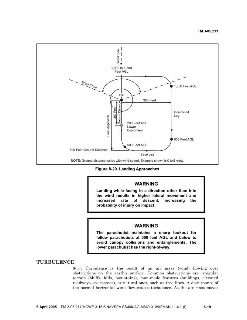
FM 3-05.211
6 April 2005 FM 3-05.211/MCWP 3-15.6/NAVSEA SS400-AG-MMO-010/AFMAN 11-411(I) 8-19
Figure 8-20. Landing Approaches
WARNING Landing while facing in a direction other than into the wind results in higher lateral movement and increased rate of descent, increasing the probability of injury on impact.
WARNING The parachutist maintains a sharp lookout for fellow parachutists at 500 feet AGL and below to avoid canopy collisions and entanglements. The lower parachutist has the right-of-way.
TURBULENCE 8-57. Turbulence is the result of an air mass (wind) flowing over obstructions on the earth’s surface. Common obstructions are irregular terrain (bluffs, hills, mountains), man-made features (buildings, elevated roadways, overpasses), or natural ones, such as tree lines. A disturbance of the normal horizontal wind flow causes turbulence. As the air mass moves

FM 3-05.211
8-20 FM 3-05.211/MCWP 3-15.6/NAVSEA SS400-AG-MMO-010/AFMAN 11-411(I) 6 April 2005
around and over the obstruction, it transforms into a complicated pattern of eddies and other irregular air movements. Turbulence generally affects the flight of the parachute at the most critical time for the parachutist—the last 200 feet of canopy flight.
8-58. In general, with ground wind speeds less than 10 knots, both the windward and leeward sides of an obstruction cause small eddies 10 to 50 feet in depth. When wind speeds are between 10 and 20 knots, obstructions can cause currents that are several hundred feet in depth. Additionally, there will still be eddies on the windward and leeward side near the obstruction. At wind speeds greater than 20 knots, currents formed on the leeward side are carried considerable distances beyond the object that created them. Only minor eddies and currents form over smooth water surfaces. Turbulence is worse over choppy swells closer to the surface of the water due to the wind flow over a constantly changing surface configuration. Over mountains, even light winds (moving air masses) pushed up mountainsides or redirected down valleys can form major eddies and air currents that have violent, abrupt characteristics. Additionally, in HAHO operations in mountains or around hilly terrain, unstable air masses form currents that continue to grow in size and complexity. The resultant turbulence can extend up to thousands of feet AGL. Turbulence is caused by heat rising off roads, concrete, and urban built-up areas and clearings.
8-59. An example of turbulence is the vortex created by aircraft taking off or landing. The turbulence created by these aircraft can invert smaller aircraft landing too closely behind them. Another example is the turbulence behind another parachutist’s canopy. The parachutist who finds himself behind this canopy will feel the turbulence it creates. Turbulence can exist around any cloud mass. Individual clouds probably will not create turbulence. Clouds that mark the leading edge of an air mass probably will contain strong downdrafts. Cloud decks capping mountain ridges will contain very strong downdrafts and abrupt turbulence. Those type cloud formations will contain rapid pressure differentials. Altimeter readings should be suspect because the parachutist could be 1,000 feet lower than the indicated altitude on the altimeter.
8-60. The parachutist should avoid at all costs clouds that contain thunderhead activity due to the violent turbulence associated with those formations.
LAND AND SEA BREEZES 8-61. The thermal differences of air masses associated with the interface along shorelines causes land and sea breezes. In the daytime, coastal landmasses warm up faster than water. The air above the land rises, causing a lower air density than over the water. The air flows from the water over the land to replace the lower air density there. This phenomenon creates onshore breezes known as sea breezes. It is most evident on clear, summer days in lower latitudes. The same phenomenon occurs in reverse in the evening due to the more rapid cooling of the landmass. The reversed process creates land breezes. The airflow over obstacles near shoreline DZs creates turbulence; when farther away from the coast, turbulence might not exist.
FM 3-05.211
6 April 2005 FM 3-05.211/MCWP 3-15.6/NAVSEA SS400-AG-MMO-010/AFMAN 11-411(I) 8-21
NOTE: If turbulence is encountered at altitude, parachutist should maintain full flight.
VALLEY AND MOUNTAIN BREEZES 8-62. Winds generally flow upslope on warm days in mountainous terrain. They flow downslope in the evening as the air masses cool. During the day, the winds create valley breezes; at night, the reverse process creates mountain breezes. These breezes, coupled with the airflow over obstacles, can cause strong and unpredictable turbulence.

This page intentionally left blank.
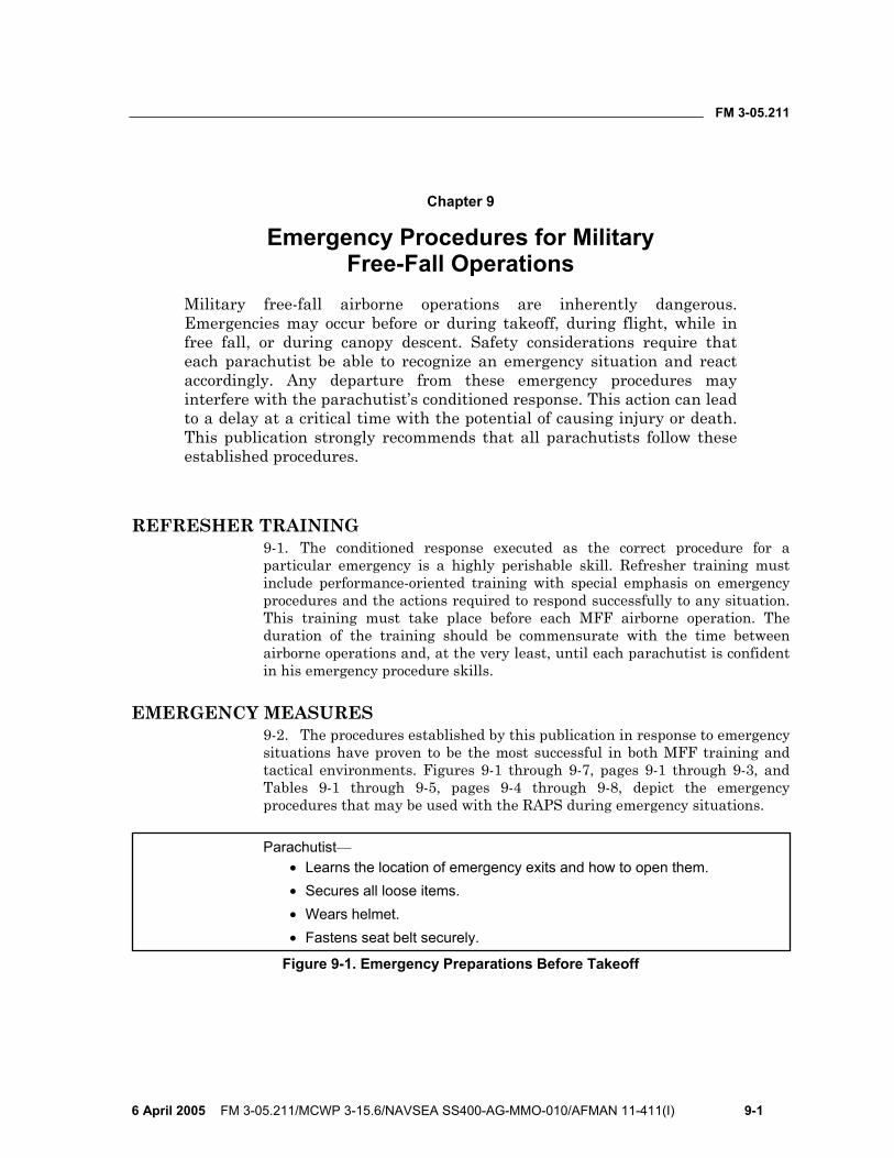
FM 3-05.211
6 April 2005 FM 3-05.211/MCWP 3-15.6/NAVSEA SS400-AG-MMO-010/AFMAN 11-411(I) 9-1
Chapter 9
Emergency Procedures for Military Free-Fall Operations
Military free-fall airborne operations are inherently dangerous. Emergencies may occur before or during takeoff, during flight, while in free fall, or during canopy descent. Safety considerations require that each parachutist be able to recognize an emergency situation and react accordingly. Any departure from these emergency procedures may interfere with the parachutist’s conditioned response. This action can lead to a delay at a critical time with the potential of causing injury or death. This publication strongly recommends that all parachutists follow these established procedures.
REFRESHER TRAINING 9-1. The conditioned response executed as the correct procedure for a particular emergency is a highly perishable skill. Refresher training must include performance-oriented training with special emphasis on emergency procedures and the actions required to respond successfully to any situation. This training must take place before each MFF airborne operation. The duration of the training should be commensurate with the time between airborne operations and, at the very least, until each parachutist is confident in his emergency procedure skills.
EMERGENCY MEASURES 9-2. The procedures established by this publication in response to emergency situations have proven to be the most successful in both MFF training and tactical environments. Figures 9-1 through 9-7, pages 9-1 through 9-3, and Tables 9-1 through 9-5, pages 9-4 through 9-8, depict the emergency procedures that may be used with the RAPS during emergency situations.
Parachutist— • Learns the location of emergency exits and how to open them. • Secures all loose items. • Wears helmet. • Fastens seat belt securely.
Figure 9-1. Emergency Preparations Before Takeoff
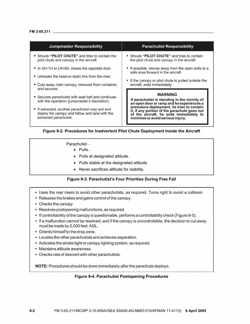
FM 3-05.211
9-2 FM 3-05.211/MCWP 3-15.6/NAVSEA SS400-AG-MMO-010/AFMAN 11-411(I) 6 April 2005
Figure 9-2. Procedures for Inadvertent Pilot Chute Deployment Inside the Aircraft
Parachutist— • Pulls. • Pulls at designated altitude. • Pulls stable at the designated altitude. • Never sacrifices altitude for stability.
Figure 9-3. Parachutist’s Four Priorities During Free Fall
Figure 9-4. Parachutist Postopening Procedures

FM 3-05.211
6 April 2005 FM 3-05.211/MCWP 3-15.6/NAVSEA SS400-AG-MMO-010/AFMAN 11-411(I) 9-3
Figure 9-5. Controllability Check
Figure 9-6. Recommended Parachute Separation
Figure 9-7. Parachutist Emergency Landing Procedures

FM 3-05.211
9-4 FM 3-05.211/MCWP 3-15.6/NAVSEA SS400-AG-MMO-010/AFMAN 11-411(I) 6 April 2005
Table 9-1. In-Flight Emergency Procedures
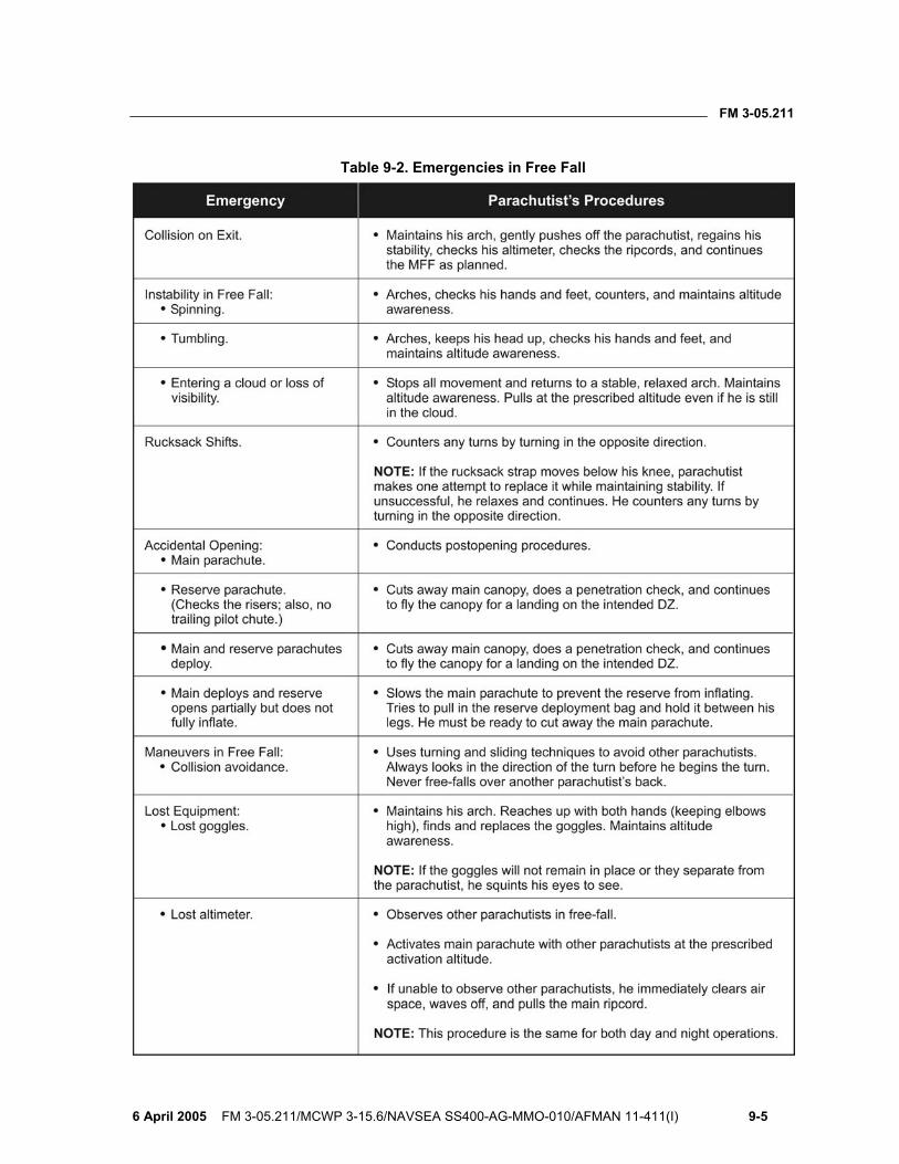
FM 3-05.211
6 April 2005 FM 3-05.211/MCWP 3-15.6/NAVSEA SS400-AG-MMO-010/AFMAN 11-411(I) 9-5
Table 9-2. Emergencies in Free Fall
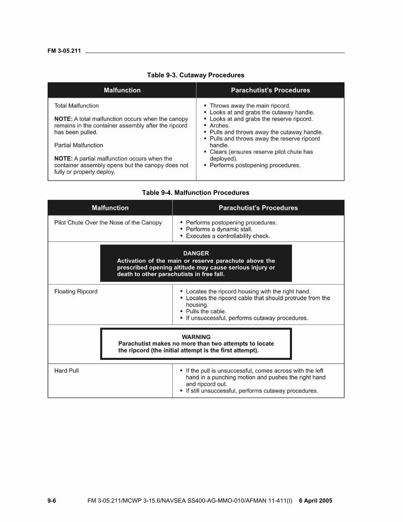
FM 3-05.211
9-6 FM 3-05.211/MCWP 3-15.6/NAVSEA SS400-AG-MMO-010/AFMAN 11-411(I) 6 April 2005
Table 9-3. Cutaway Procedures
Table 9-4. Malfunction Procedures
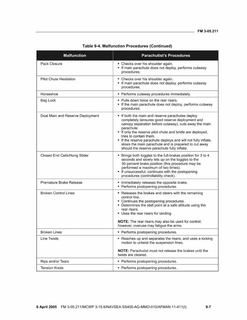
FM 3-05.211
6 April 2005 FM 3-05.211/MCWP 3-15.6/NAVSEA SS400-AG-MMO-010/AFMAN 11-411(I) 9-7
Table 9-4. Malfunction Procedures (Continued)
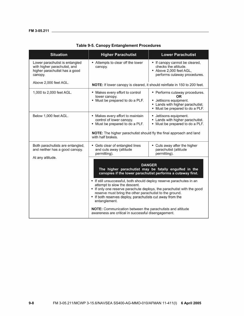
FM 3-05.211
9-8 FM 3-05.211/MCWP 3-15.6/NAVSEA SS400-AG-MMO-010/AFMAN 11-411(I) 6 April 2005
Table 9-5. Canopy Entanglement Procedures
FM 3-05.211
6 April 2005 FM 3-05.211/MCWP 3-15.6/NAVSEA SS400-AG-MMO-010/AFMAN 11-411(I) 10-1
Chapter 10
High-Altitude High-Opening and Limited-Visibility Operations
Standoff delivery techniques offer the commander a unique method for infiltrating trained operational elements. The RAPS gives the commander a tactical capability to infiltrate these elements by parachute without requiring the aircraft to overfly the intended DZ. These elements can be released at an offset release point and navigate long distances under canopy. The flight characteristics of the reserve parachutes of the RAPSs are identical to the main parachutes. This fact increases the chance of a successful infiltration should a cutaway from the main parachute take place because of a malfunction. NOTE: For parachute systems that have a smaller reserve canopy than the main canopy, the mission commander planning the operation must plan for contingencies that address the reduced glide capability should a cutaway from the main parachute take place. Canopy openings at 6,000 feet AGL or above are considered HAHO jumps.
TECHNIQUES AND REQUIREMENTS 10-1. The parachutist uses a combination of delayed free-fall and HAHO techniques if making exits at an altitude above 25,000 feet MSL. He can also deploy his parachute at intermediate altitudes to minimize the chance of parachute damage or injury to himself upon canopy deployment, while using the glide advantage of the RAPS.
WARNING The maximum deployment altitude of the MC-4 RAPS is 25,000 feet MSL.
10-2. The commander should consider altitude requirements when conducting training at altitudes. The recommended altitude for routine training is 17,500 feet MSL. Conducting training at this altitude eliminates the need for oxygen prebreathing and minimizes the chance of parachute damage and injury to the parachutist due to opening forces. The parachutist is also less likely to encounter physiological problems and cold-weather injuries.
10-3. HAHO standoff parachuting requires extensive airspace clearance. Additionally, this training must take place in areas having alternate DZs should the parachutist (or element) not be able to reach the primary DZ.
FM 3-05.211
10-2 FM 3-05.211/MCWP 3-15.6/NAVSEA SS400-AG-MMO-010/AFMAN 11-411(I) 6 April 2005
10-4. Accurate weather data is essential. Wind directions and speeds are critical for route planning. Air temperatures are important for preparing against exposure injuries.
WARNING Icing conditions may occur at high altitude or during adverse weather conditions. Ice formation on the parachute canopy adversely affects its flight characteristics by increasing the rate of descent and decreasing its responsiveness.
SPECIAL EQUIPMENT 10-5. Special precautions must be taken to prevent exposure injuries to the parachutist at high altitude. Gloves are necessary to protect the hands. The gloves, however, must not interfere with the manual activation of the main parachute or the performance of emergency procedures. The following paragraphs discuss special equipment that the parachutist must use.
TOGGLE EXTENSIONS 10-6. Toggle extensions permit the parachutist to keep his hands at waist level during extended flights. They also allow for improved blood circulation to the hands and arms and lessen fatigue. Another technique is to leave the brakes stowed and simply steer the parachute using the risers to make needed corrections.
WARNING Parachutists must not use the toggle extensions for flaring.
COMPASS 10-7. Each parachutist needs a compass to determine direction should he separate from the group or during limited visibility, such as when passing through cloud layers. A marine-type, oil-dampened compass that is unaffected by pressure changes or cold weather is recommended. The compass must show direction regardless of its mounted attitude on the parachutist. The parachutist takes care when mounting the compass to avoid erroneous readings caused by interference from radios or other electronic navigation aids. He adjusts the declination of his compass while wearing all his accompanying equipment. This action will account for all magnetic variances caused by accompanying metal objects.
ELECTRONIC NAVIGATION DEVICES 10-8. The parachutist mounts the electronic navigation or guidance devices on the waistband enclosed in a padded container; thus, they do not interfere
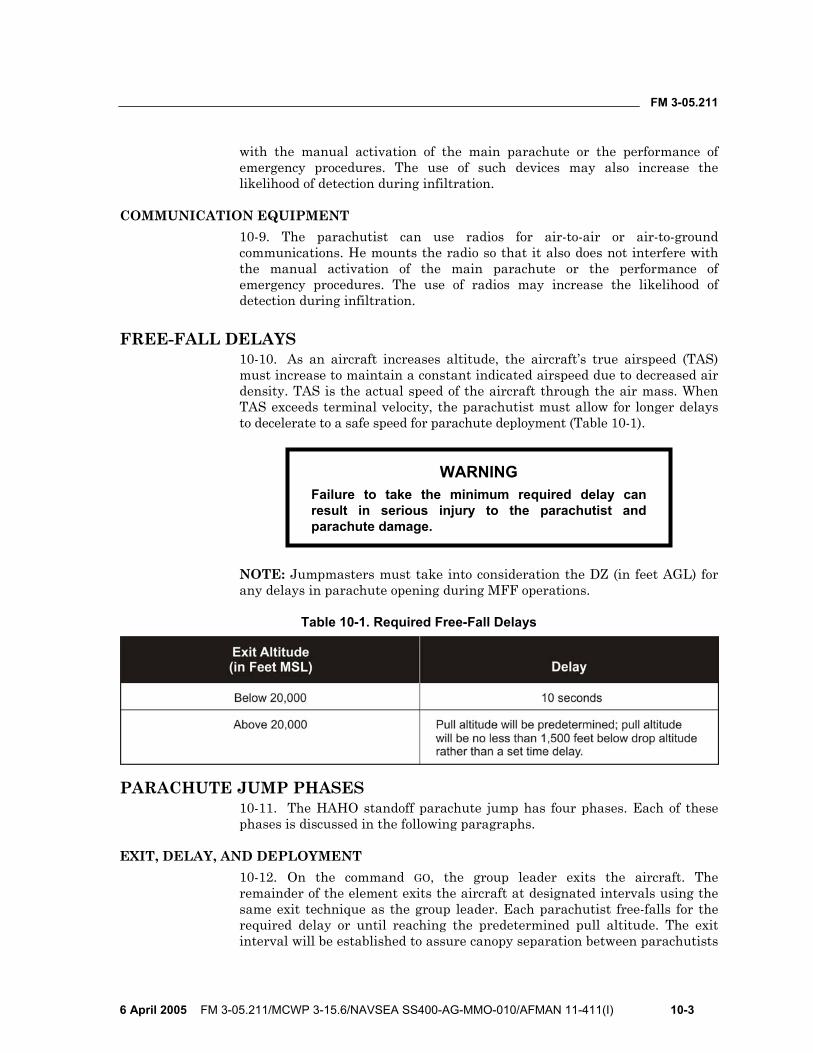
FM 3-05.211
6 April 2005 FM 3-05.211/MCWP 3-15.6/NAVSEA SS400-AG-MMO-010/AFMAN 11-411(I) 10-3
with the manual activation of the main parachute or the performance of emergency procedures. The use of such devices may also increase the likelihood of detection during infiltration.
COMMUNICATION EQUIPMENT 10-9. The parachutist can use radios for air-to-air or air-to-ground communications. He mounts the radio so that it also does not interfere with the manual activation of the main parachute or the performance of emergency procedures. The use of radios may increase the likelihood of detection during infiltration.
FREE-FALL DELAYS 10-10. As an aircraft increases altitude, the aircraft’s true airspeed (TAS) must increase to maintain a constant indicated airspeed due to decreased air density. TAS is the actual speed of the aircraft through the air mass. When TAS exceeds terminal velocity, the parachutist must allow for longer delays to decelerate to a safe speed for parachute deployment (Table 10-1).
WARNING Failure to take the minimum required delay can result in serious injury to the parachutist and parachute damage.
NOTE: Jumpmasters must take into consideration the DZ (in feet AGL) for any delays in parachute opening during MFF operations.
Table 10-1. Required Free-Fall Delays
PARACHUTE JUMP PHASES 10-11. The HAHO standoff parachute jump has four phases. Each of these phases is discussed in the following paragraphs.
EXIT, DELAY, AND DEPLOYMENT 10-12. On the command GO, the group leader exits the aircraft. The remainder of the element exits the aircraft at designated intervals using the same exit technique as the group leader. Each parachutist free-falls for the required delay or until reaching the predetermined pull altitude. The exit interval will be established to assure canopy separation between parachutists
FM 3-05.211
10-4 FM 3-05.211/MCWP 3-15.6/NAVSEA SS400-AG-MMO-010/AFMAN 11-411(I) 6 April 2005
at opening. The exit interval will be based on type of aircraft, its speed, and the mission requirements.
10-13. A parachutist experiencing a malfunction must immediately start emergency procedures to minimize loss of altitude.
10-14. Upon deployment, the group leader checks with the element for malfunctions, then assumes the initial flight heading. Should a member of the element be beneath the group, the element must execute the rehearsed tactical plan (lose altitude to reform the group or follow the low parachutist).
ASSEMBLY UNDER CANOPY 10-15. The opening altitude should be a minimum of 1,000 feet above any cloud layer to allow enough altitude for the element to assemble under canopy. Each parachutist flies his canopy to his rehearsed position within the formation. Each parachutist assumes the group leader’s heading.
FLIGHT IN FORMATION 10-16. The “wedge” and the “trail” formations are the easiest to control and to maintain in flight (Figure 10-1, page 10-5). The group leader (low parachutist) has the primary responsibility for navigation. All parachutists should have navigation aids when they jump.
10-17. Element members in the formation maintain relative airspeed and position with the group leader. They do this maneuver by trimming their canopies using the trim tabs on the front risers and by braking.
10-18. Under limited visibility conditions, such as when passing through a cloud layer, each parachutist goes to half brakes and maintains the compass heading until he regains visual contact with the formation or as stated in unit SOP. Each parachutist must maintain altitude awareness and keep a sharp lookout for other parachutists.
FINAL APPROACH AND LANDING 10-19. The group leader initiates the landing pattern at about 1,000 feet AGL in the landing area. Each parachutist removes any trim tab settings to prevent injury on landing from the increased forward speed.
10-20. The landings are staggered to avoid the turbulence directly above and to the rear of the other ram-air canopies. Each parachutist prepares to do a PLF should visibility prevent him from seeing the ground.
LIMITED-VISIBILITY OPERATIONS 10-21. MFF infiltrations during periods of limited visibility (adverse weather or darkness) have a higher chance of success than strictly daylight operations. Limited-visibility infiltrations offer surprise and increased security due to reduced enemy observation capability. Limited-visibility operations require a high degree of skill and individual discipline. A well-rehearsed tactical plan executed by personnel proficient in MFF skills is critical to success.
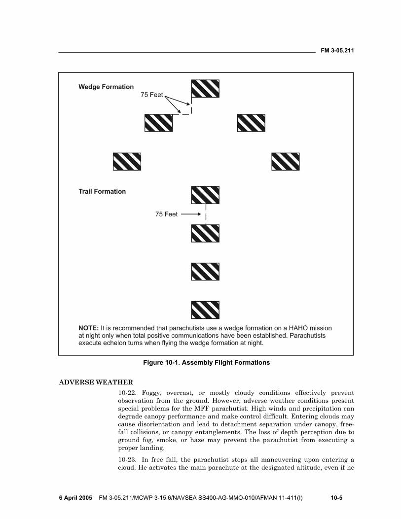
FM 3-05.211
6 April 2005 FM 3-05.211/MCWP 3-15.6/NAVSEA SS400-AG-MMO-010/AFMAN 11-411(I) 10-5
Figure 10-1. Assembly Flight Formations
ADVERSE WEATHER 10-22. Foggy, overcast, or mostly cloudy conditions effectively prevent observation from the ground. However, adverse weather conditions present special problems for the MFF parachutist. High winds and precipitation can degrade canopy performance and make control difficult. Entering clouds may cause disorientation and lead to detachment separation under canopy, free-fall collisions, or canopy entanglements. The loss of depth perception due to ground fog, smoke, or haze may prevent the parachutist from executing a proper landing.
10-23. In free fall, the parachutist stops all maneuvering upon entering a cloud. He activates the main parachute at the designated altitude, even if he
FM 3-05.211
10-6 FM 3-05.211/MCWP 3-15.6/NAVSEA SS400-AG-MMO-010/AFMAN 11-411(I) 6 April 2005
has not passed through the cloud layer. In clouds under canopy, he flies the canopy at the half-brakes position to help prevent a mid-air collision during limited visibility.
NIGHT OPERATIONS 10-24. Night MFF parachuting offers the same advantages as parachuting during adverse weather, especially during the first quarter, new moon, and last quarter moon phases. Night free-fall parachuting is the most psychologically demanding of parachute operations. Extensive training must take place at night. During this training, the parachutist develops confidence in the equipment and his abilities.
10-25. Commanders must weigh the tactical situation when placing lighting devices on the parachutist and on the parachute canopy for safety and control during free fall and canopy flight. At a minimum, illumination devices are used for altimeters and other instruments.
10-26. The use of oxygen dramatically improves night vision. Wearing the oxygen mask until the landing is a recommended procedure. The commander may consider using oxygen for all night free-fall operations, even if the jumping altitude does not require it.
10-27. The jumpmaster can use night vision devices to help him while spotting from the aircraft. The parachutist can also use them during canopy flight as an aid to navigation and formation flying. He must have extensive experience flying and landing with night vision goggles to overcome the loss of depth perception. An additional factor to consider is that the night vision goggles will seriously impair his night vision after using them for extended periods.
WARNING Night vision goggles should not be worn during free fall because they restrict the parachutist’s ability to locate the ripcord handle and the cutaway handle.
10-28. The lack of depth perception at night may prevent the parachutist from executing a proper landing. The parachutist flies the parachute at the half-brakes position and performs a PLF on contact with the ground. Various night illumination techniques exist to identify parachutists, group leaders, or subunit elements while under canopy. Some techniques involve attaching the devices in the aircraft and some must be activated and placed on the canopy before packing the parachute. Some of these techniques include rheostatic electroluminescent riser lights, chemical lights on the parachutist’s body and on the risers, and other electrical systems placed in pockets on the canopy’s top skin.
FM 3-05.211
6 April 2005 FM 3-05.211/MCWP 3-15.6/NAVSEA SS400-AG-MMO-010/AFMAN 11-411(I) 11-1
Chapter 11
Military Free-Fall Drop Zone Operations A DZ is any designated area where personnel and equipment may be delivered by means of parachute or free drop. DZs for MFF operations are selected during premission planning using all available intelligence sources. DZs are selected by the ground unit commander and are located where they can best support the ground tactical plan. The air mission commander recommends approach headings and selects initial and subsequent timing points based upon the routes to the DZ, terrain obstructions, ease of DZ identification, and enemy defenses. Final approval of selected DZs is a joint decision made by the ground unit commander and the supporting air unit. This chapter outlines the basic selection criteria, markings, and procedures used in support of MFF operations, as well as the qualifications and responsibilities of key DZ support personnel.
RESPONSIBILITIES 11-1. DZ size and selection are the joint responsibility of the air component commander (ACC) or Commander, Air Force Special Operations Command (COMAFSOC), and the supported force commander. The supporting air unit is responsible for airdrop accuracy and safety of flight. The supported ground unit is responsible for establishment, operation, safety on the DZ, and the elimination or acceptance of ground hazards associated with the DZ. The jumpmaster is responsible for accuracy when jumpmaster-directed release procedures are used. AFI 13-217, Drop Zone and Landing Zone Operations, has additional information.
DROP ZONE SELECTION CRITERIA 11-2. The joint force commander gives guidance on DZ size in operation plans and operation orders. The ground unit commander selects the general area of the DZ where it will best support the ground tactical plan. DZ selection should be based on the following criteria:
• Mission supporting. Some of the main considerations when selecting a DZ that supports the mission are—
Method of insertion (HALO or HAHO). Elevation and drop altitude. Location and capability of enemy forces. Recognizability during limited visibility. Distance from the objective area. Terrain between the DZ and the objective area.
FM 3-05.211
11-2 FM 3-05.211/MCWP 3-15.6/NAVSEA SS400-AG-MMO-010/AFMAN 11-411(I) 6 April 2005
Built-up areas. Time available for movement to the objective area. Amount of equipment being carried. Physical characteristics of available DZs and surrounding areas. Relative number of obstacles in the area. Proximity to alternate and contingency DZs.
• Supporting aircraft. When considering the capabilities of the supporting aircraft, parachutists take the following into account:
Type of aircraft. Capabilities of the aircraft. Skill level of the aircrew. Availability of backup aircraft if the primary aircraft has
mechanical problems. • Infiltration route. The primary, alternate, and contingency DZs should
be selected so that the aircraft can overfly them in order without making major course corrections. Air routes to and from the DZ should not conflict with other air operations, restrictive terrain, restrictive airspace, or fall within the enemy’s air defense umbrella.
• Security. The DZ must provide security from the enemy threat. The DZ should be located away from enemy positions and built-up areas.
• Safety. • Weather and astronomical conditions. Seasonal weather and
astronomical conditions in the area must be considered. If conducting a water jump, the tides, waves, currents, and sea state must be considered.
• Size. There is no minimum size for MFF DZs according to STANAG 3570 and AFI 13-217. The jumpmaster will determine the minimum size of a MFF DZ based upon the experience and capabilities of the parachutists. An area 50 meters by 100 meters is the recommended minimum DZ size for training.
DROP ZONE SURVEYS 11-3. A DZ survey is required for all airdrop training missions involving U.S. personnel and equipment. Completing the DZ survey process involves a physical inspection of the DZ and documenting the DZ information on AF Form 3823, Drop Zone Survey. The using unit completes the DZ survey and forwards it through appropriate channels for review and approval. The using unit is defined as the unit whose personnel or equipment are being airdropped. The DZ survey review process involves the following steps:
• Step 1: The surveyor (AF Form 3823, item 4a) physically surveys the DZ and completes the ground portion of AF Form 3823. Once completed, AF Form 3823 is forwarded to the ground operations review authority for approval (AF Form 3823, item 4c). The ground operations review authority is normally the surveyor’s commander or designated
FM 3-05.211
6 April 2005 FM 3-05.211/MCWP 3-15.6/NAVSEA SS400-AG-MMO-010/AFMAN 11-411(I) 11-3
representative. This review ensures the AF Form 3823 is complete, accurate, and meets the criteria for planned airborne operations.
• Step 2: Using unit forwards the survey to the USAF regional/wings tactic office for a safety-of-flight review (AF Form 3823, item 4d). A safety-of-flight review is completed by an airdrop-qualified pilot or navigator on all DZ surveys. The purpose of a safety-of-flight review is to ensure an aircraft can safely ingress and egress the DZ.
• Step 3: Regional/wings tactic office forwards the survey to the appropriate operations group commander for review and final approval (AF Form 3823, item 4e). This approval assures that the safety-of-flight review has been conducted and the DZ is considered safe for specified airdrop operations.
• Step 4: Once AF Form 3823, item 4e, has been completed the survey is approved for use. Copies of the survey are forwarded to HQ AMC/DOKT, 402 Scott Drive, Scott AFB, IL 62225-5320 for inclusion into the Zone Availability Report (ZAR) database.
11-4. The ZAR is a comprehensive listing of approved assault zones available for use by DOD. Use of the ZAR will expedite mission planning, enhance safety, and avoid duplication of surveys. Information contained in the ZAR does not replace the need for a completed DZ survey before conducting airdrop operations. Completed surveys are available via facsimile (FAX) on-demand system (also located at Scott Air Force Base [AFB], Illinois [IL]) at DSN 576-2899 or commercial (618) 256-2899.
DROP ZONE PERSONNEL QUALIFICATIONS AND RESPONSIBILITIES
11-5. The airborne commander designates key personnel for each airborne operation. These key personnel are the primary jumpmaster (PJM), assistant jumpmaster (AJM), safety personnel, oxygen safety personnel (when required), departure airfield control officer (DACO), drop zone safety officer (DZSO)/drop zone support team leader (DZSTL), and the malfunction officer (MO). The qualifications and responsibilities of DZ support personnel are listed in the paragraphs below. FM 3-21.220, Static Line Parachuting Techniques and Training, includes further discussion of responsibilities during airborne operations.
DROP ZONE SAFETY OFFICER/DROP ZONE SUPPORT TEAM LEADER 11-6. The DZSO/DZSTL must be a commissioned officer, warrant officer, or noncommissioned officer (NCO) (E5 or above for proficiency jumps; E6 for tactical jumps). The airborne commander makes sure the DZSO/DZSTL is a current qualified static-line or MFF jumpmaster, has performed the duties of assistant DZSO/DZSTL in support of an airborne operation involving personnel or heavy equipment at least once, and is familiar with MFF operations IAW this manual. The MFF jumpmaster briefs the DZSO/DZSTL on the DZ markings, communications, and operating procedures that will be used.
FM 3-05.211
11-4 FM 3-05.211/MCWP 3-15.6/NAVSEA SS400-AG-MMO-010/AFMAN 11-411(I) 6 April 2005
11-7. The DZSO/DZSTL has overall operational responsibility for the DZ. He conducts a ground or aerial reconnaissance of the DZ before the drop to make sure there are no safety hazards. Other responsibilities include—
• Establishing personal liaison with the USAF drop zone control officer (DZCO) and STT, and discussing drop procedures (USAF troop carrier aircraft).
• Clearing the DZ of unauthorized personnel and vehicles. • Briefing and posting road guards, if required. • Ensuring medical personnel are in position. • Ensuring that the DZ is operational 1 hour before TOT. • Establishing communications with the DACO not later than (NLT)
1 hour before TOT. • Maintaining continuous surface wind readings NLT 12 minutes before
TOT. (Peacetime ground wind training limits will not exceed 18 knots.) There are no winds aloft restrictions.
• Giving the pilot the ground winds and the CLEAR TO DROP or NO DROP signal 2 minutes prior to the scheduled TOT.
NOTE: The CLEAR TO DROP or NO DROP signal that is relayed to the pilot 2 minutes prior to TOT does not indicate the final wind reading. A NO DROP signal can be relayed to the pilot, any time afterwards, if surface winds increase beyond the authorized limit. • Receiving from the pilot the number of parachutists that have exited
the aircraft after each pass. • Relaying strike reports to the aircraft pilot. • During night drops, ensuring that all lights on or next to the DZ
(except for DZ markings) are turned off 15 minutes before drop time and remain off during the jump.
• Directing the recovery crew to assist parachutists and to retrieve equipment in trees.
• Assisting in medical evacuation of injured personnel from the DZ. • Immediately after the completion of the jump, asking the pilot if any
personnel or equipment did not drop, and then relaying this information to the airborne commander on the DZ.
• In the event a malfunction occurs, securing the equipment and allowing no one to disturb it until the MO has completed his on-site investigation. If an MO or an NCO is not physically located on the DZ, the DZSO/DZSTL turns it over to an appropriate parachute maintenance facility.
• Recording the necessary information for the parachute operation report.
• Closing the DZ.
FM 3-05.211
6 April 2005 FM 3-05.211/MCWP 3-15.6/NAVSEA SS400-AG-MMO-010/AFMAN 11-411(I) 11-5
UNITED STATES AIR FORCE DROP ZONE CONTROL OFFICER 11-8. The USAF DZCO represents the airlift commander. He supervises all USAF personnel on the DZ. He also observes drop operations. Other responsibilities include—
• Evaluating all factors that might adversely affect safety. • If conditions make drop operations unsafe, directing the STT to relay
that information to the appropriate USAF commander as soon as possible and to display the established NO DROP signal on the DZ.
• Directing the use of STT equipment. • Canceling drops when requested to do so by the Army DZSO. • Keeping the Army DZSO advised on ground wind speed on the DZ. • Preparing the necessary log and reports for submission to the airlift
control element or the appropriate USAF commander.
SPECIAL TACTICS TEAM 11-9. The STT marks the DZs with proper navigational and identification aids. The STT establishes ground-to-air communications at DZs, as well as communications with designated control agencies. Other responsibilities include—
• Providing the U.S. Army DZSO with surface weather and low-level (up to 1,500 feet) winds aloft observations.
• Exercising air traffic control over aircraft in the vicinity of a specific DZ, as directed.
MALFUNCTION OFFICER 11-10. The investigation of personnel, parachutes, and equipment malfunctions receives the highest priority and is secondary in priority only to medical aid for the injured. This investigation supersedes all other aspects of the operation, to include ground tactical play. Prompt and accurate investigations and reporting could save lives and equipment. The report provides data to determine if a system or procedural training change is necessary to prevent future occurrences. The MO is subordinate to the DZSO/DZSTL and is a member of the DZ support team. Any assistance required by the MO must pass through the DZSO/DZSTL, who controls the DZ.
11-11. The MO must be a commissioned officer, warrant officer, or NCO (minimum grade of E5). The MO must be a trained parachute rigger who is familiar with airdrop, parachute recovery, and aircraft personnel parachute escape systems IAW AR 59-4, Joint Airdrop Inspection Records, Malfunction Investigations, and Activity Reporting. The exception to the minimum grade requirement is that for Air Force unilateral training loads, the DZ MO will be a minimum grade of E4.
11-12. The organization that provides the air items will provide the MO. He will be present on the DZ during all personnel and equipment drops and will
FM 3-05.211
11-6 FM 3-05.211/MCWP 3-15.6/NAVSEA SS400-AG-MMO-010/AFMAN 11-411(I) 6 April 2005
be familiar with requirements. The MO must have the following minimum equipment in his possession during duty performance:
• A communication capability with the DZ control party. • A good-quality camera to take photos of malfunctions or incidents
(video camera preferred). Photographic equipment is essential for the proper performance of MO duties. Pictures of malfunctions greatly assist in investigations.
• The forms and clerical supplies necessary to tag equipment and initiate reports.
• Binoculars or night vision devices. • Transportation to move around the DZ.
11-13. If a malfunction occurs, the MO immediately conducts an on-site investigation of the causes of the malfunction. The MO photographs the malfunctioned equipment, or the malfunction as it happens, and the malfunction site that shows possible causes of the malfunction. The MO secures, identifies, tags, and numbers airdrop equipment involved in the malfunction incident. The MO then prepares and submits DD Form 1748-2, Joint Airdrop Malfunction Report (Personnel-Cargo), to report all airdrop malfunctions (IAW AR 59-4), as well as any other required reports.
NOTE: MOs must prepare complete and accurate MFF accident reports. The fielding of new MFF equipment and the introduction of new MFF procedures depends on the feedback of the reporting process to detect accident patterns. There are several forms used by the Services in addition to DD Form 1748-2. Appendix E contains an example of the amount of detail that should be included in an accident report.
MILITARY FREE-FALL DROP ZONE MARKINGS 11-14. MFF infiltrations usually take place on blind DZs due to the general ineffectiveness of visual markings when viewed from high altitudes (HALO) and extended distances (HAHO). DZ identification is normally by location in relation to major terrain features.
11-15. DZ markings are sometimes used when the tactical situation permits, and it is desirable to indicate wind direction to the descending parachutists (Figure 11-1, page 11-7). FM 3-05.210, Special Forces Air Operations; FM 3-21.38, Pathfinder Operations; and AFI 13-217 outline approved marking techniques.
HIGH-ALTITUDE RELEASE POINT AND MILITARY FREE-FALL DROP ZONE DETECTION
11-16. Location in relation to major terrain features identifies the HARP. Appendix F contains methods of computing the HARP. The HARP may be marked, if known, when the tactical situation permits. In heavily vegetated, mountainous, or urban terrain and during conditions of restricted visibility, DZs and HARPs may be difficult to detect. Electronic beacons or radar transponders and appropriate tracking devices help aircraft personnel and parachutists locate DZs or HARPs. Expedient methods, such as balloons and pyrotechnics, may also help aircraft personnel and parachutists locate DZs or HARPs. In situations where secrecy is important, aircraft and parachutists
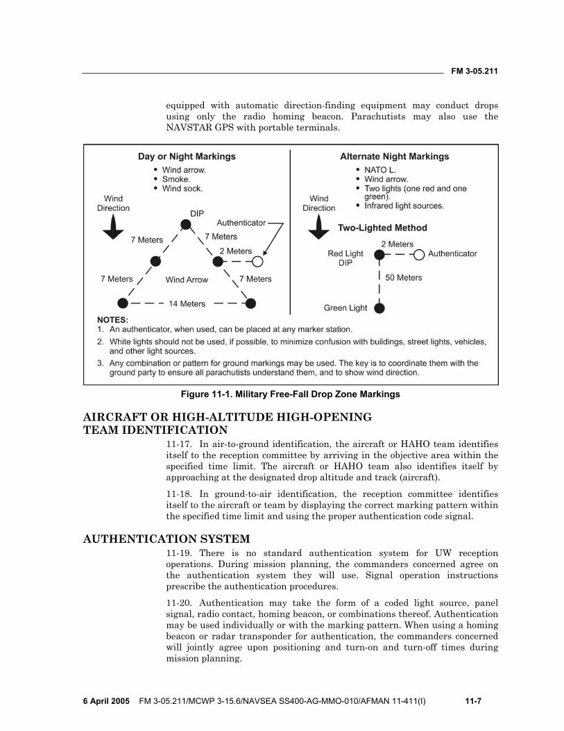
FM 3-05.211
6 April 2005 FM 3-05.211/MCWP 3-15.6/NAVSEA SS400-AG-MMO-010/AFMAN 11-411(I) 11-7
equipped with automatic direction-finding equipment may conduct drops using only the radio homing beacon. Parachutists may also use the NAVSTAR GPS with portable terminals.
Figure 11-1. Military Free-Fall Drop Zone Markings
AIRCRAFT OR HIGH-ALTITUDE HIGH-OPENING TEAM IDENTIFICATION
11-17. In air-to-ground identification, the aircraft or HAHO team identifies itself to the reception committee by arriving in the objective area within the specified time limit. The aircraft or HAHO team also identifies itself by approaching at the designated drop altitude and track (aircraft).
11-18. In ground-to-air identification, the reception committee identifies itself to the aircraft or team by displaying the correct marking pattern within the specified time limit and using the proper authentication code signal.
AUTHENTICATION SYSTEM 11-19. There is no standard authentication system for UW reception operations. During mission planning, the commanders concerned agree on the authentication system they will use. Signal operation instructions prescribe the authentication procedures.
11-20. Authentication may take the form of a coded light source, panel signal, radio contact, homing beacon, or combinations thereof. Authentication may be used individually or with the marking pattern. When using a homing beacon or radar transponder for authentication, the commanders concerned will jointly agree upon positioning and turn-on and turn-off times during mission planning.

This page intentionally left blank.
FM 3-05.211
6 April 2005 FM 3-05.211/MCWP 3-15.6/NAVSEA SS400-AG-MMO-010/AFMAN 11-411(I) 12-1
Chapter 12
Deliberate Water Military Free-Fall Operations This chapter outlines the policies, procedures, and restrictions for conducting deliberate MFF operations into water DZs. Individual Services will use their applicable regulations and SOPs when conducting Service-pure MFF operations into water DZs. The procedures outlined in this chapter are different from the emergency water-landing procedures discussed in Chapter 9.
ADDITIONAL SUPPORT REQUIREMENTS 12-1. All basic parachute support operations outlined in Chapter 11 must be used when conducting deliberate water parachute operations. Listed below is the additional support needed for parachute operations using water DZs. Parachutists should refer to individual Service regulations for additional restrictions.
PARACHUTIST RECOVERY BOATS 12-2. A minimum of one power-driven parachutist recovery boat is required for every parachutist being dropped on the same pass if parachutists are not combat swimmer, combat diver, waterborne infiltration course (WIC), scout swimmer, or second-class swimmer certified. If the parachutists are combat swimmer, combat diver, WIC, scout swimmer, or second-class swimmer certified, then the requirement is one parachutist recovery boat for every four parachutists on the same pass.
12-3. The number of parachutists exiting the aircraft per pass will be limited to the number of parachutist recovery boats available. Parachutist recovery boats must have an inflatable boat or ladder rigged alongside if they have a freeboard of more than three feet or if the boats do not provide an easy platform for recovery of personnel. Boats assigned as parachutist recovery platforms may only be used to assist in the recovery of equipment after all parachutists have been recovered. The boat coxswain cannot act as the DZSO/DZSTL, MO, safety swimmer, or medic.
EQUIPMENT RECOVERY BOATS 12-4. A minimum of one power-driven boat is required for every two equipment platforms dropped on the same pass. Equipment recovery boats are to be used in the recovery of equipment parachutes and platforms.
12-5. Recovery boats assigned to recover personnel do not meet this requirement when parachutists and equipment are on the same pass. Equipment recovery boats must be large enough to recover cargo parachutes and platforms. The boat coxswain cannot act as the DZSO/DZSTL, MO, safety swimmer, or medic.
FM 3-05.211
12-2 FM 3-05.211/MCWP 3-15.6/NAVSEA SS400-AG-MMO-010/AFMAN 11-411(I) 6 April 2005
SAFETY SWIMMERS 12-6. Safety swimmers must be qualified swimmer/divers IAW Service publications. A minimum of one safety swimmer is required to be onboard each recovery boat. The safety swimmer must have fins, a facemask, a knife, a flare, and an inflatable life preserver. For night drops, safety swimmers should have a light that is visible for 1 mile (for example, a chemlite) and an emergency light visible for 3 miles (for example, a strobe light).
12-7. The safety swimmer will be used to recover personnel and equipment and assist parachutists as needed. The safety swimmer cannot be assigned additional duties, such as the DZSTL, MO, boat coxswain, or medic.
PARACHUTIST REQUIREMENTS 12-8. Currency requirements for conducting deliberate MFF water jumps include the following:
• Parachutist swimmer qualification. Parachutists must be qualified swimmers IAW Service regulations before making a water parachute drop.
• First water jump. Personnel must be current parachutists to conduct their first water jump. Their first water jump must be made during the day and without combat equipment.
• First night water jump. Parachutist training requirements for conducting night water jumps will be IAW Service publications.
• Jumper currency. Personnel who are not current can use a water jump for refresher provided it is done during the day and without combat equipment.
EQUIPMENT REQUIREMENTS 12-9. Equipment requirements for conducting deliberate MFF water jumps include the following:
• Minimum equipment. Each parachutist must have the following minimum equipment for a water jump:
Life preserver. Long-sleeved top or wet suit. Booties, coral shoes, jungle boots, or equivalent. Fins. Helmet. Knife and approved day/night flare. Chemlite (night operations only).
• Equipment waivers. Helmets can be waived by the commanding officer based on operational requirements and a risk assessment (for example, wet suit hoods or cold weather hoods).
• Flotation. Parachutists must ensure they wear enough flotation to enable them to be positively buoyant in the water. If an injury occurs to the parachutist, he must be able to float without swimming.

FM 3-05.211
6 April 2005 FM 3-05.211/MCWP 3-15.6/NAVSEA SS400-AG-MMO-010/AFMAN 11-411(I) 12-3
• Inflatable life jacket. When using a UDT life preserver, parachutists must route the parachute harness chest strap underneath the life jacket to allow proper inflation in an emergency.
CAUTION Routing the chest strap over the UDT vest will prevent the life vest from inflating properly and may cause injury to the parachutist.
• Altimeters. Altimeters are required for every jump except water jumps with delays less than 10 seconds. Units should coordinate for waivers when conducting deliberate water MFF parachute operations without an altimeter IAW their Service regulations.
• Automatic ripcord releases. ARRs are required for all MFF parachute operations. There are no waterproof ARRs currently available. Units should coordinate for a waiver IAW their Service regulations when conducting deliberate water MFF parachute operations without an ARR.
• Safety lanyards. Only 80-pound cotton tape is authorized as the safety lanyard for swim fins. The safety lanyards must be short enough not to catch or snag on anything during exit.
• Reserve static line. When making a deliberate water jump with the military RAPS, parachutists must disconnect the RSL once they have a good canopy over their heads. This action will prevent the reserve from being deployed if the main is cut away while in the water.
• Placement of fins. During an exit for a water parachute drop, the jumper may wear his fins as described in one of the three methods listed below. From each configuration, the parachutist must be able to put the fins on either under canopy or in the water. The fins may be—
Worn on feet as normal with 80-pound safety lanyards. This method may be used if the parachutist does not have to walk far to exit. Short fins are recommended if the parachutist must walk in the aircraft to exit.
Taped vertically to shins with foot through strap and 80-pound safety line. Holding the fin vertically with the strap down, the parachutist places his foot through the fin strap. He tapes the top of the fin to the front of his leg, folding the end of the tape over to make a quick-release tab. He then secures the fin to his ankle with a short piece of 80-pound cotton tape.
Attached or fastened to a separate belt. The fins must be worn in front on the parachutist’s thigh or in the back under the pack tray. Fins must be placed so as not to interfere with parachute deployment or the parachutist’s ability to remain stable during free fall.
12-10. Whenever possible, the parachutist should wear his fins on exit. If the parachutist does not have his fins on during exit, then he should wait to put them on until after entering the water. This step will allow the parachutist
FM 3-05.211
12-4 FM 3-05.211/MCWP 3-15.6/NAVSEA SS400-AG-MMO-010/AFMAN 11-411(I) 6 April 2005
to concentrate on canopy grouping at low altitudes. Aircraft configuration and SOP will determine the proper location.
DROP ZONE REQUIREMENTS AND MARKINGS 12-11. DZ requirements and markings for conducting deliberate MFF water jumps include the following:
• Establishment of the DZ. The DZ must be established not less than 60 minutes before the TOT to allow time for the DZSO to monitor DZ conditions.
• Surface winds. Surface winds shall not exceed 18 knots. • Sea state. Sea state shall not exceed limits IAW Service publications. • Water depth. The depth of the water must be at least 10 feet. • Water temperature. Minimum safe water temperature for personnel
drops is 50 degrees F (10 degrees Celsius) unless an appropriate exposure suit is worn. Partial or full exposure suits should be considered whenever water temperatures are below 72 degrees F.
• Air-to-ground communications. Personnel must establish a positive visual or electronic signal for DZ identification before the drop for water parachute operations. Only a positive visual or electronic signal for DZ identification is required; however, radio communications are highly recommended to assist in verifying the DZ (USASOC units require radio communications). Parachutists must use positive night visual signals (for example, beacons, strobes) for night drops to avoid confusion and to aid in positive identification.
• DZ communication. All DZ safety craft must be equipped with boat-to-boat radio communications.
• DZ configuration. The DZ is configured IAW Service regulations.
PARACHUTIST PROCEDURES FOR WATER JUMPS 12-12. Parachutist procedures for conducting MFF water jumps include the following:
• Water parachute jump. Procedures for a premeditated water parachute jump after exiting the aircraft are described below. Parachutists—
Check parachute and locate other parachutists. Parachutists turn canopy toward the DZ.
Disconnect RSL and release waistband. Continue to steer and group with other parachutists to the target. At no lower than 200 feet above the water, turn into the wind and
release the chest strap (500 feet recommended with combat equipment).
Confirm leg strap snap hook locations. Flare canopy to land (land with half brakes for night jumps). After entering the water, release leg straps and crawl out of the
harness.
FM 3-05.211
6 April 2005 FM 3-05.211/MCWP 3-15.6/NAVSEA SS400-AG-MMO-010/AFMAN 11-411(I) 12-5
Put fins on, if required. Swim to the center of trailing edge (tail). Hand the center of the trailing edge (tail) and harness to recovery
boat. • Reserve static line. When making an MFF water jump with the MC-4,
parachutists must ensure they disconnect the RSL once under a good canopy. This action will prevent the reserve from being activated if the main is cut away while in the water.
• Life preserver use. If the parachutist is unable to stay above the water, he must either add air using the oral inflation tube or inflate his life preserver with the CO2.
• High winds. If a parachutist is being dragged in high winds, he must roll over on his back and attempt to collapse the canopy by pulling in on one steering toggle. If this is not possible, he then performs a cutaway on the RAPS. He must ensure the RSL system is disconnected before cutaway of the main.
• No-wind landings. In a no-wind landing condition, the canopy may possibly land on top of the parachutist. If this occurs, parachutist must remain calm and avoid getting tangled in the suspension lines. He should create an air pocket by splashing the water and lifting the canopy above the water. Then he finds a seam and follows it to the edge of the canopy. In an emergency, the parachutist uses his knife to cut through the canopy.
• Equipment flotation. The reserve parachute will float for a short time; however, if the parachute starts to sink, parachutist should make no attempt to hang on or recover it.
DROP ZONE PROCEDURES FOR PICKUP OF PARACHUTISTS AND EQUIPMENT
12-13. DZ procedures for pickup of parachutists and equipment include the following:
• Recovery boat assignments. Recovery boats must have assigned duties by the DZSTL so as to minimize confusion during the recovery procedure. These assignments must be briefed by the DZSTL/DZSO before setting up the DZ.
• Recovery priority. Recovery boats will first pick up any parachutist who signals he is in trouble or has deployed his reserve parachute. Parachutists always have priority for pickup over cargo chutes or equipment.
• Approaching parachutists in the water. Boat coxswains must approach the parachutist perpendicular to the wind to avoid drifting or being blown over the parachutist or the parachute. Caution must always be taken not to operate the propeller (screws) while the parachutist is alongside in the water. The engine should be placed in neutral. If the parachute gets entangled in the propeller (screws), the boat coxswain turns the motor off while the safety swimmer frees it.
FM 3-05.211
12-6 FM 3-05.211/MCWP 3-15.6/NAVSEA SS400-AG-MMO-010/AFMAN 11-411(I) 6 April 2005
• Recovery of ram-air parachute systems. The parachutist must hand the center of the trailing edge (tail) and then the harness to the boat crewman. The suspension lines should be daisy-chained starting from the harness end. After the lines are daisy-chained, the canopy will be pulled in from the trailing edge (tail) first to allow the water to drain out the leading edge (nose).
• Recovery of parachutes and platforms. Recovery of equipment after a water parachute jump is only administrative. Combat conditions will call for the sinking of parachutes and platforms. All swimmers except one should be in the combat rubber raiding craft (CRRC) or move away from it before sinking the platform. Parachutes and platforms may be intentionally sunk on training jumps as long as procedures are used to prevent the equipment from resurfacing and becoming a navigation hazard.
NIGHT WATER PARACHUTE OPERATIONS 12-14. For night water MFF parachute training, parachutists are required to be equipped with a light visible for 1 mile (chemlite), an emergency light visible for 3 miles (strobe), and a flare for emergencies in the water. During free fall and under canopy, parachutists display a light (for example, a chemlite) visible for 1 mile as a safety measure to prevent mid-air collisions or entanglements. Parachutists are not required to be marked for combat situations.
WATER JUMPS WITH COMBAT EQUIPMENT 12-15. Requirements for water jumps with combat equipment include the following:
• Combat equipment limitations. Jumping with combat equipment is authorized for water parachute jumps. Parachutists should minimize the amount of equipment they jump with in the water for safety reasons. Parachutists are not authorized to jump with rifles rigged on themselves. They must place rifles and other weapons in weapons bags. Rifles rigged on the parachutists may easily entangle with suspension lines in the water. Whenever possible, parachutists place as much equipment as possible in the CRRC load except for individual survival gear.
• Jumper currency. Parachutists conducting water parachute operations with combat equipment must be current and have previously made at least one noncombat equipment water parachute jump.
• Equipment rigging. Equipment packs jumped on the individual must be rigged to be positively buoyant in water. Equipment should be dip-tested for buoyancy before the jump. The equipment is rigged and attached as described in Chapter 5.
• Parachutist procedures. When jumping equipment, it is recommended to make the turn on final approach at 500 feet, but no lower than 200 feet, to allow additional time to unfasten the chest strap and lower the equipment. After the parachutist enters the water, he must disconnect the equipment after getting out of the harness.
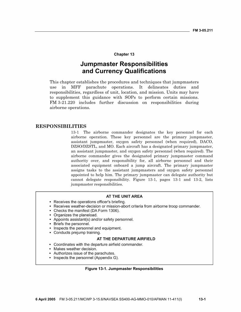
FM 3-05.211
6 April 2005 FM 3-05.211/MCWP 3-15.6/NAVSEA SS400-AG-MMO-010/AFMAN 11-411(I) 13-1
Chapter 13
Jumpmaster Responsibilities and Currency Qualifications
This chapter establishes the procedures and techniques that jumpmasters use in MFF parachute operations. It delineates duties and responsibilities, regardless of unit, location, and mission. Units may have to supplement this guidance with SOPs to perform certain missions. FM 3-21.220 includes further discussion on responsibilities during airborne operations.
RESPONSIBILITIES 13-1 The airborne commander designates the key personnel for each airborne operation. These key personnel are the primary jumpmaster, assistant jumpmaster, oxygen safety personnel (when required), DACO, DZSO/DZSTL, and MO. Each aircraft has a designated primary jumpmaster, an assistant jumpmaster, and oxygen safety personnel (when required). The airborne commander gives the designated primary jumpmaster command authority over, and responsibility for, all airborne personnel and their associated equipment onboard a jump aircraft. The primary jumpmaster assigns tasks to the assistant jumpmasters and oxygen safety personnel appointed to help him. The primary jumpmaster can delegate authority but cannot delegate responsibility. Figure 13-1, pages 13-1 and 13-2, lists jumpmaster responsibilities.
Figure 13-1. Jumpmaster Responsibilities
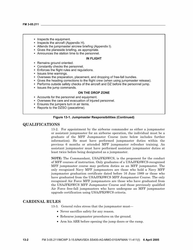
FM 3-05.211
13-2 FM 3-05.211/MCWP 3-15.6/NAVSEA SS400-AG-MMO-010/AFMAN 11-411(I) 6 April 2005
Figure 13-1. Jumpmaster Responsibilities (Continued)
QUALIFICATIONS 13-2. For appointment by the airborne commander as either a jumpmaster or assistant jumpmaster for an airborne operation, the individual must be a graduate of the MFF Jumpmaster Course (note below includes further information). He must have performed jumpmaster duties within the previous 6 months or attended MFF jumpmaster refresher training. An assistant jumpmaster must have performed assistant jumpmaster duties at least twice before being designated as a jumpmaster.
NOTE: The Commandant, USAJFKSWCS, is the proponent for the conduct of MFF courses of instruction. Only graduates of a USAJFKSWCS-recognized MFF jumpmaster course may perform duties as an MFF jumpmaster. The only recognized Navy MFF jumpmasters are those who hold a Navy MFF jumpmaster graduation certificate dated before 16 June 1989 or those who have graduated from the USAJFKSWCS MFF Jumpmaster Course. The only recognized Air Force MFF jumpmasters are those who have graduated from the USAJFKSWCS MFF Jumpmaster Course and those previously qualified Air Force free-fall jumpmasters who have undergone an MFF jumpmaster upgrade certification using USAJFKSWCS criteria.
CARDINAL RULES 13-3. General rules stress that the jumpmaster must—
• Never sacrifice safety for any reason. • Rehearse jumpmaster procedures on the ground. • Arm his ARR before opening the jump doors or the ramp.
FM 3-05.211
6 April 2005 FM 3-05.211/MCWP 3-15.6/NAVSEA SS400-AG-MMO-010/AFMAN 11-411(I) 13-3
• Face the open jump door when in flight. • Maintain a firm handhold on the aircraft when working in or close to
an open jump door or ramp. • Never allow anyone in or near an open jump door or ramp who is not
wearing a helmet and safety harness or parachute. The helmet requirement may be waived for deliberate water jumps.
CURRENCY AND REQUALIFICATION REQUIREMENTS 13-4. An MFF jumpmaster must be USAJFKSWCS-trained or have formally undergone transitional training in a proponent-recognized school environment from the MC-3 system to the RAPS. He must have performed primary or assistant jumpmaster duties within the last 6 months where parachutists actually exited the aircraft while using a jumpmaster-directed release.
13-5. Previously qualified MFF jumpmasters who do not meet proficiency and currency requirements will meet the following requalification requirements:
• Undergo MFF parachutist refresher training outlined in Appendix B. • Receive JMPI training for the primary MFF parachute system used in
his parent unit. • Receive refresher training in wind drift (HARP) calculation for MFF
mission profiles. • Receive oxygen equipment refresher training. • Perform assistant jumpmaster duties for one MFF jump. • Execute under-canopy navigation techniques specific to the navigation
aids unique to the parent unit. An MFF jumpmaster who meets the currency criteria will conduct the requalification and refresher training.
NOTE: Whenever possible, a jumpmaster-directed release should be used to enhance MFF jumpmaster skills.

This page intentionally left blank.
FM 3-05.211
6 April 2005 FM 3-05.211/MCWP 3-15.6/NAVSEA SS400-AG-MMO-010/AFMAN 11-411(I) A-1
Appendix A
Military Free-Fall Critical Task Lists This appendix includes the critical task lists for the MFF Basic Course, the Advanced MFF Course, and the MFF Jumpmaster Course.
MILITARY FREE-FALL BASIC COURSE A-1. Module 1: Ground Training (4 Tasks):
• Objective: To become familiar with rigging combat equipment, donning the MC-4 parachute system, packing the MC-4, and body stabilization techniques.
• Individual tasks: 331-202-2000: Rig Combat Equipment for MFF Operations. 331-202-2001: Don the MC-4 Ram-Air Parachute System. 331-202-2010: Pack the MC-4 Ram-Air Canopy. 331-202-2011: Perform Body Stabilization Techniques.
A-2. Module 2: Emergency Procedures (4 Tasks): • Objective: To become proficient in MFF emergencies. • Individual tasks:
331-202-2002: React to Aircraft Emergencies During Free-Fall Operations.
331-202-2004: React to Emergencies While in Military Free Fall. 331-202-2006: React to MC-4 Ram-Air Canopy Emergencies During
Descent. 331-202-2009: React to Emergencies Associated With Landing an
MC-4 Ram-Air Canopy.
A-3. Module 3: Aircraft and Jump Procedures (4 Tasks): • Objective: To become proficient in aircraft procedures, jumping, and
maneuvering the MC-4 parachute system. • Individual tasks:
331-202-2005: Maneuver the MC-4 Ram-Air Canopy to a Designated Drop Zone.
331-202-2008: Jump From an Aircraft During MFF Operations While Wearing Combat Equipment and Portable Bailout System.
331-202-2012: Conduct MFF Operations Using Oxygen. 331-202-2013: Respond to Aircraft Procedure Signals and Jump
Commands During MFF Airborne Operations.
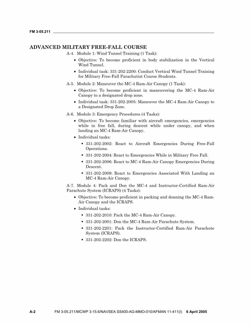
FM 3-05.211
A-2 FM 3-05.211/MCWP 3-15.6/NAVSEA SS400-AG-MMO-010/AFMAN 11-411(I) 6 April 2005
ADVANCED MILITARY FREE-FALL COURSE A-4. Module 1: Wind Tunnel Training (1 Task):
• Objective: To become proficient in body stabilization in the Vertical Wind Tunnel.
• Individual task: 331-202-2200: Conduct Vertical Wind Tunnel Training for Military Free-Fall Parachutist Course Students.
A-5. Module 2: Maneuver the MC-4 Ram-Air Canopy (1 Task): • Objective: To become proficient in maneuvering the MC-4 Ram-Air
Canopy to a designated drop zone. • Individual task: 331-202-2005: Maneuver the MC-4 Ram-Air Canopy to
a Designated Drop Zone.
A-6. Module 3: Emergency Procedures (4 Tasks): • Objective: To become familiar with aircraft emergencies, emergencies
while in free fall, during descent while under canopy, and when landing an MC-4 Ram-Air Canopy.
• Individual tasks: 331-202-2002: React to Aircraft Emergencies During Free-Fall
Operations. 331-202-2004: React to Emergencies While in Military Free Fall. 331-202-2006: React to MC-4 Ram-Air Canopy Emergencies During
Descent. 331-202-2009: React to Emergencies Associated With Landing an
MC-4 Ram-Air Canopy.
A-7. Module 4: Pack and Don the MC-4 and Instructor-Certified Ram-Air Parachute System (ICRAPS) (4 Tasks):
• Objective: To become proficient in packing and donning the MC-4 Ram-Air Canopy and the ICRAPS.
• Individual tasks: 331-202-2010: Pack the MC-4 Ram-Air Canopy. 331-202-2001: Don the MC-4 Ram-Air Parachute System. 331-202-2201: Pack the Instructor-Certified Ram-Air Parachute
System (ICRAPS). 331-202-2202: Don the ICRAPS.
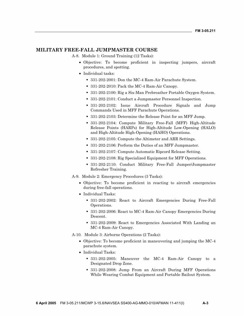
FM 3-05.211
6 April 2005 FM 3-05.211/MCWP 3-15.6/NAVSEA SS400-AG-MMO-010/AFMAN 11-411(I) A-3
MILITARY FREE-FALL JUMPMASTER COURSE A-8. Module 1: Ground Training (12 Tasks):
• Objective: To become proficient in inspecting jumpers, aircraft procedures, and spotting.
• Individual tasks: 331-202-2001: Don the MC-4 Ram-Air Parachute System. 331-202-2010: Pack the MC-4 Ram-Air Canopy. 331-202-2100: Rig a Six-Man Prebreather Portable Oxygen System. 331-202-2101: Conduct a Jumpmaster Personnel Inspection. 331-202-2102: Issue Aircraft Procedure Signals and Jump
Commands Used in MFF Parachute Operations. 331-202-2103: Determine the Release Point for an MFF Jump. 331-202-2104: Compute Military Free-Fall (MFF) High-Altitude
Release Points (HARPs) for High-Altitude Low-Opening (HALO) and High-Altitude High-Opening (HAHO) Operations.
331-202-2105: Compute the Altimeter and ARR Settings. 331-202-2106: Perform the Duties of an MFF Jumpmaster. 331-202-2107: Compute Automatic Ripcord Release Setting. 331-202-2108: Rig Specialized Equipment for MFF Operations. 331-202-2110: Conduct Military Free-Fall Jumper/Jumpmaster
Refresher Training.
A-9. Module 2: Emergency Procedures (3 Tasks): • Objective: To become proficient in reacting to aircraft emergencies
during free-fall operations. • Individual Tasks:
331-202-2002: React to Aircraft Emergencies During Free-Fall Operations.
331-202-2006: React to MC-4 Ram-Air Canopy Emergencies During Descent.
331-202-2009: React to Emergencies Associated With Landing an MC-4 Ram-Air Canopy.
A-10. Module 3: Airborne Operations (2 Tasks): • Objective: To become proficient in maneuvering and jumping the MC-4
parachute system. • Individual Tasks:
331-202-2005: Maneuver the MC-4 Ram-Air Canopy to a Designated Drop Zone.
331-202-2008: Jump From an Aircraft During MFF Operations While Wearing Combat Equipment and Portable Bailout System.

FM 3-05.211
A-4 FM 3-05.211/MCWP 3-15.6/NAVSEA SS400-AG-MMO-010/AFMAN 11-411(I) 6 April 2005
CRITICAL TASK LIST
Rig Combat Equipment for MFF Operations 331-202-2000
Condition: Given a rucksack, an improved equipment attaching sling (IEAS), two quick releases, a lowering line, and an M16 rifle.
Standards: The Soldier must— 1. Inspect the rucksack, the rifle, and related equipment for serviceability. 2. Rig a rear-mounted rucksack for use in MFF parachute operations. 3. Rig a front-mounted rucksack for use in MFF parachute operations. 4. Rig an M16 rifle for use in MFF parachute operations. 5. Execute procedures for donning and lowering a rear-mounted rucksack. 6. Execute procedures for donning and lowering the front-mounted rucksack.
Don the MC-4 Ram-Air Parachute System
331-202-2001
Condition: Given the required MFF-associated items, an FF-2 automatic ripcord release (ARR), and a Ram-Air Parachute System (RAPS).
Standards: The Soldier must— 1. Identify the required MFF-associated items. 2. Inspect the component parts of the FF-2 ARR. 3. Attach the FF-2 ARR (with the appropriate millibar setting) to the RAPS. 4. Don the RAPS. 5. Perform postjump recovery of MFF equipment.
Pack the MC-4 Ram-Air Canopy
331-202-2010
Condition: Given a Ram-Air Parachute System.
Standards: Within 30 minutes, the Soldier must— 1. Place the main parachute canopy into the proper layout. 2. Fold the canopy. 3. Place the canopy into the deployment bag. 4. Form the locking stows. 5. Place the deployment bag into the harness container. 6. S-fold the bridle line; compress the pilot chute; and close the bottom flap, the
left flap, and the right flap on the main container. 7. Close the container.
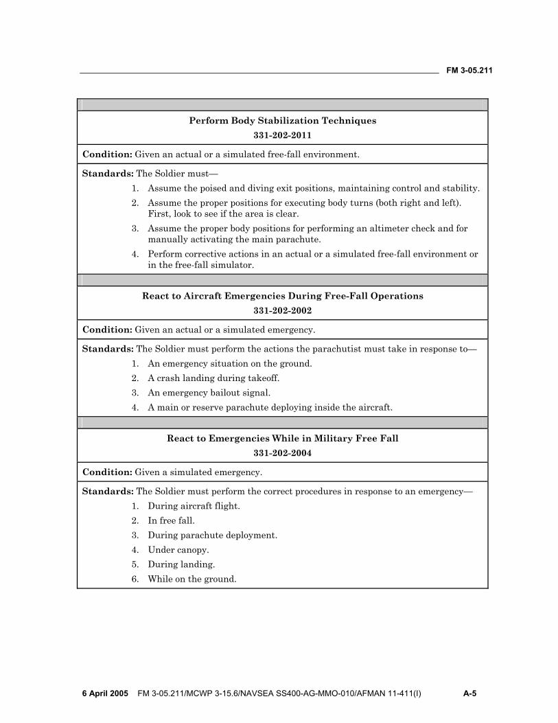
FM 3-05.211
6 April 2005 FM 3-05.211/MCWP 3-15.6/NAVSEA SS400-AG-MMO-010/AFMAN 11-411(I) A-5
Perform Body Stabilization Techniques
331-202-2011
Condition: Given an actual or a simulated free-fall environment.
Standards: The Soldier must— 1. Assume the poised and diving exit positions, maintaining control and stability. 2. Assume the proper positions for executing body turns (both right and left).
First, look to see if the area is clear. 3. Assume the proper body positions for performing an altimeter check and for
manually activating the main parachute. 4. Perform corrective actions in an actual or a simulated free-fall environment or
in the free-fall simulator.
React to Aircraft Emergencies During Free-Fall Operations 331-202-2002
Condition: Given an actual or a simulated emergency.
Standards: The Soldier must perform the actions the parachutist must take in response to— 1. An emergency situation on the ground. 2. A crash landing during takeoff. 3. An emergency bailout signal. 4. A main or reserve parachute deploying inside the aircraft.
React to Emergencies While in Military Free Fall
331-202-2004
Condition: Given a simulated emergency.
Standards: The Soldier must perform the correct procedures in response to an emergency— 1. During aircraft flight. 2. In free fall. 3. During parachute deployment. 4. Under canopy. 5. During landing. 6. While on the ground.
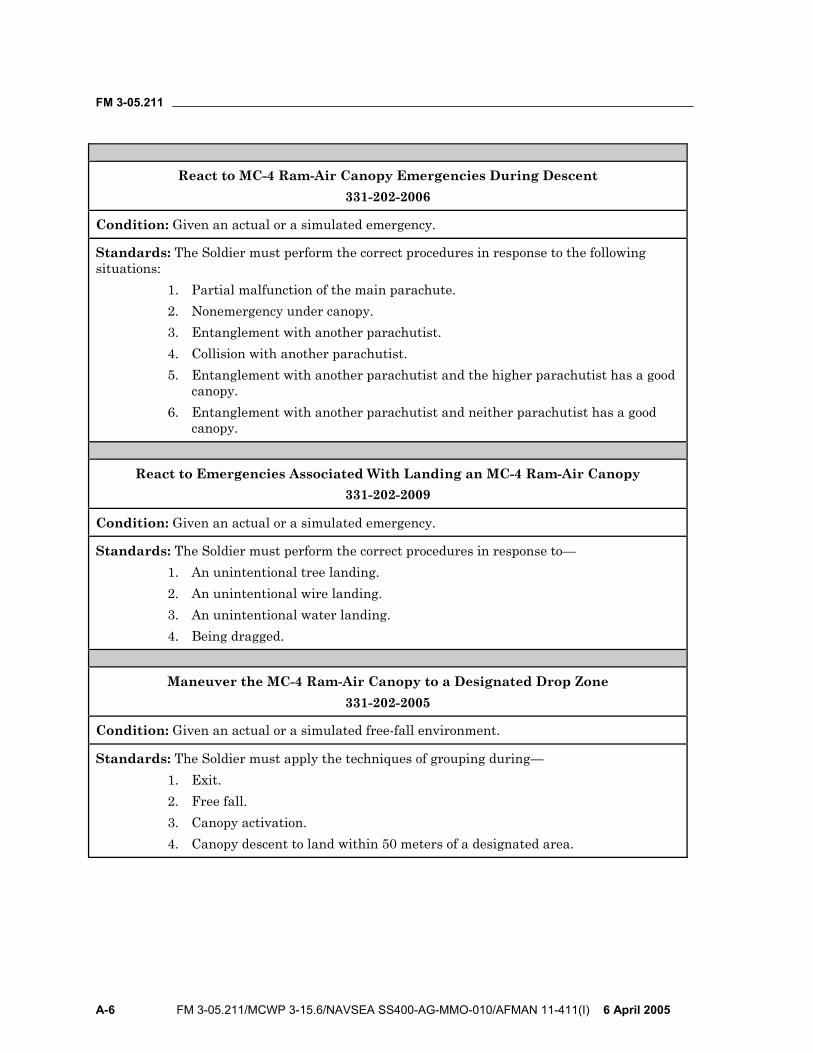
FM 3-05.211
A-6 FM 3-05.211/MCWP 3-15.6/NAVSEA SS400-AG-MMO-010/AFMAN 11-411(I) 6 April 2005
React to MC-4 Ram-Air Canopy Emergencies During Descent
331-202-2006
Condition: Given an actual or a simulated emergency.
Standards: The Soldier must perform the correct procedures in response to the following situations:
1. Partial malfunction of the main parachute. 2. Nonemergency under canopy. 3. Entanglement with another parachutist. 4. Collision with another parachutist. 5. Entanglement with another parachutist and the higher parachutist has a good
canopy. 6. Entanglement with another parachutist and neither parachutist has a good
canopy.
React to Emergencies Associated With Landing an MC-4 Ram-Air Canopy 331-202-2009
Condition: Given an actual or a simulated emergency.
Standards: The Soldier must perform the correct procedures in response to— 1. An unintentional tree landing. 2. An unintentional wire landing. 3. An unintentional water landing. 4. Being dragged.
Maneuver the MC-4 Ram-Air Canopy to a Designated Drop Zone
331-202-2005
Condition: Given an actual or a simulated free-fall environment.
Standards: The Soldier must apply the techniques of grouping during— 1. Exit. 2. Free fall. 3. Canopy activation. 4. Canopy descent to land within 50 meters of a designated area.
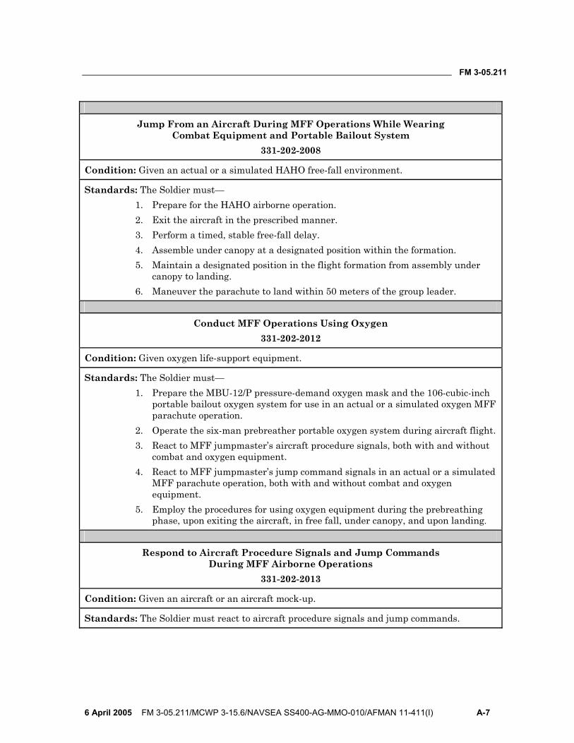
FM 3-05.211
6 April 2005 FM 3-05.211/MCWP 3-15.6/NAVSEA SS400-AG-MMO-010/AFMAN 11-411(I) A-7
Jump From an Aircraft During MFF Operations While Wearing
Combat Equipment and Portable Bailout System 331-202-2008
Condition: Given an actual or a simulated HAHO free-fall environment.
Standards: The Soldier must— 1. Prepare for the HAHO airborne operation. 2. Exit the aircraft in the prescribed manner. 3. Perform a timed, stable free-fall delay. 4. Assemble under canopy at a designated position within the formation. 5. Maintain a designated position in the flight formation from assembly under
canopy to landing. 6. Maneuver the parachute to land within 50 meters of the group leader.
Conduct MFF Operations Using Oxygen
331-202-2012
Condition: Given oxygen life-support equipment.
Standards: The Soldier must— 1. Prepare the MBU-12/P pressure-demand oxygen mask and the 106-cubic-inch
portable bailout oxygen system for use in an actual or a simulated oxygen MFF parachute operation.
2. Operate the six-man prebreather portable oxygen system during aircraft flight. 3. React to MFF jumpmaster’s aircraft procedure signals, both with and without
combat and oxygen equipment. 4. React to MFF jumpmaster’s jump command signals in an actual or a simulated
MFF parachute operation, both with and without combat and oxygen equipment.
5. Employ the procedures for using oxygen equipment during the prebreathing phase, upon exiting the aircraft, in free fall, under canopy, and upon landing.
Respond to Aircraft Procedure Signals and Jump Commands
During MFF Airborne Operations 331-202-2013
Condition: Given an aircraft or an aircraft mock-up.
Standards: The Soldier must react to aircraft procedure signals and jump commands.
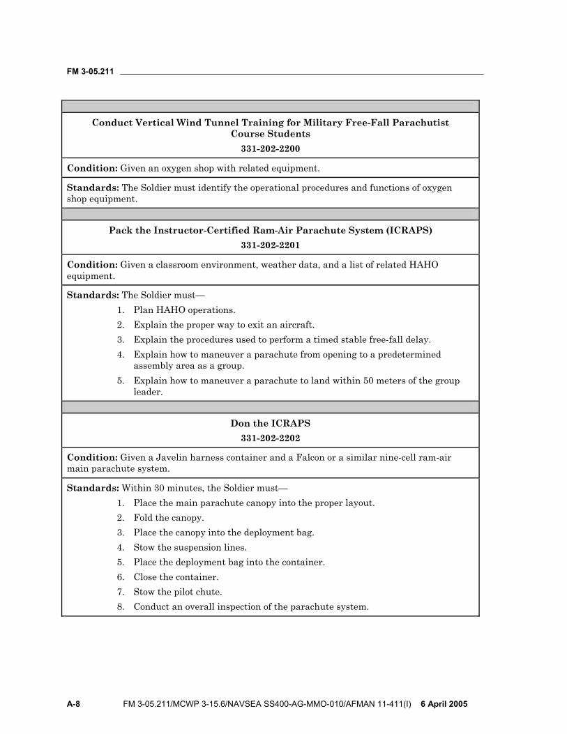
FM 3-05.211
A-8 FM 3-05.211/MCWP 3-15.6/NAVSEA SS400-AG-MMO-010/AFMAN 11-411(I) 6 April 2005
Conduct Vertical Wind Tunnel Training for Military Free-Fall Parachutist
Course Students 331-202-2200
Condition: Given an oxygen shop with related equipment.
Standards: The Soldier must identify the operational procedures and functions of oxygen shop equipment.
Pack the Instructor-Certified Ram-Air Parachute System (ICRAPS) 331-202-2201
Condition: Given a classroom environment, weather data, and a list of related HAHO equipment.
Standards: The Soldier must— 1. Plan HAHO operations. 2. Explain the proper way to exit an aircraft. 3. Explain the procedures used to perform a timed stable free-fall delay. 4. Explain how to maneuver a parachute from opening to a predetermined
assembly area as a group. 5. Explain how to maneuver a parachute to land within 50 meters of the group
leader.
Don the ICRAPS 331-202-2202
Condition: Given a Javelin harness container and a Falcon or a similar nine-cell ram-air main parachute system.
Standards: Within 30 minutes, the Soldier must— 1. Place the main parachute canopy into the proper layout. 2. Fold the canopy. 3. Place the canopy into the deployment bag. 4. Stow the suspension lines. 5. Place the deployment bag into the container. 6. Close the container. 7. Stow the pilot chute. 8. Conduct an overall inspection of the parachute system.
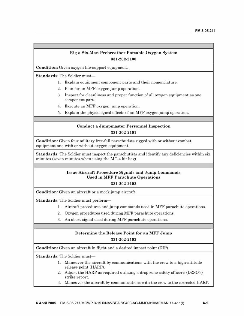
FM 3-05.211
6 April 2005 FM 3-05.211/MCWP 3-15.6/NAVSEA SS400-AG-MMO-010/AFMAN 11-411(I) A-9
Rig a Six-Man Prebreather Portable Oxygen System
331-202-2100
Condition: Given oxygen life-support equipment.
Standards: The Soldier must— 1. Explain equipment component parts and their nomenclature. 2. Plan for an MFF oxygen jump operation. 3. Inspect for cleanliness and proper function of all oxygen equipment as one
component part. 4. Execute an MFF oxygen jump operation. 5. Explain the physiological effects of an MFF oxygen jump operation.
Conduct a Jumpmaster Personnel Inspection
331-202-2101
Condition: Given four military free-fall parachutists rigged with or without combat equipment and with or without oxygen equipment.
Standards: The Soldier must inspect the parachutists and identify any deficiencies within six minutes (seven minutes when using the MC-4 kit bag).
Issue Aircraft Procedure Signals and Jump Commands Used in MFF Parachute Operations
331-202-2102
Condition: Given an aircraft or a mock jump aircraft.
Standards: The Soldier must perform— 1. Aircraft procedures and jump commands used in MFF parachute operations. 2. Oxygen procedures used during MFF parachute operations. 3. An abort signal used during MFF parachute operations.
Determine the Release Point for an MFF Jump
331-202-2103
Condition: Given an aircraft in flight and a desired impact point (DIP).
Standards: The Soldier must— 1. Maneuver the aircraft by communications with the crew to a high-altitude
release point (HARP). 2. Adjust the HARP as required utilizing a drop zone safety officer’s (DZSO’s)
strike report. 3. Maneuver the aircraft by communications with the crew to the corrected HARP.

FM 3-05.211
A-10 FM 3-05.211/MCWP 3-15.6/NAVSEA SS400-AG-MMO-010/AFMAN 11-411(I) 6 April 2005
Compute Military Free-Fall (MFF) High-Altitude Release Points (HARPs)
for High-Altitude Low-Opening (HALO) and High-Altitude High-Opening (HAHO) Operations
331-202-2104
Condition: Given wind direction, wind velocity, and a desired impact point (DIP).
Standards: The Soldier must— 1. Compute a HARP for an MFF HALO operation. 2. Plot a HARP for an MFF HALO operation. 3. Compute a HARP for an MFF HAHO operation. 4. Plot a HARP for an MFF HAHO operation. 5. Compute a HARP with a dogleg for an MFF operation. 6. Compute incompatible wind direction data and an MFF HARP. 7. Average incompatible wind direction data.
Compute the Altimeter and ARR Settings
331-202-2105
Condition: Given an MA2-30 altimeter, an FF-2 ARR, an Irvin calculator, the drop zone field elevation, the activation altitude, and the aircraft altimeter setting.
Standards: The Soldier must— 1. Explain the function of the FF-2 ARR as a backup safety device. 2. Compute the millibar setting in hundredths of inches of mercury. 3. Set the FF-2 ARR within 2 millibars of the correct setting. 4. Prepare the FF-2 ARR for use. 5. Explain the procedure for setting the altimeter. 6. Set the altimeter to within 100 feet of the correct setting.
Perform the Duties of an MFF Jumpmaster
331-202-2106
Condition: Given an airborne operation assignment and an actual or mock jump aircraft.
Standards: The Soldier must execute the jumpmaster duties— 1. In the unit area. 2. At the departure airfield. 3. During flight. 4. On the drop zone.
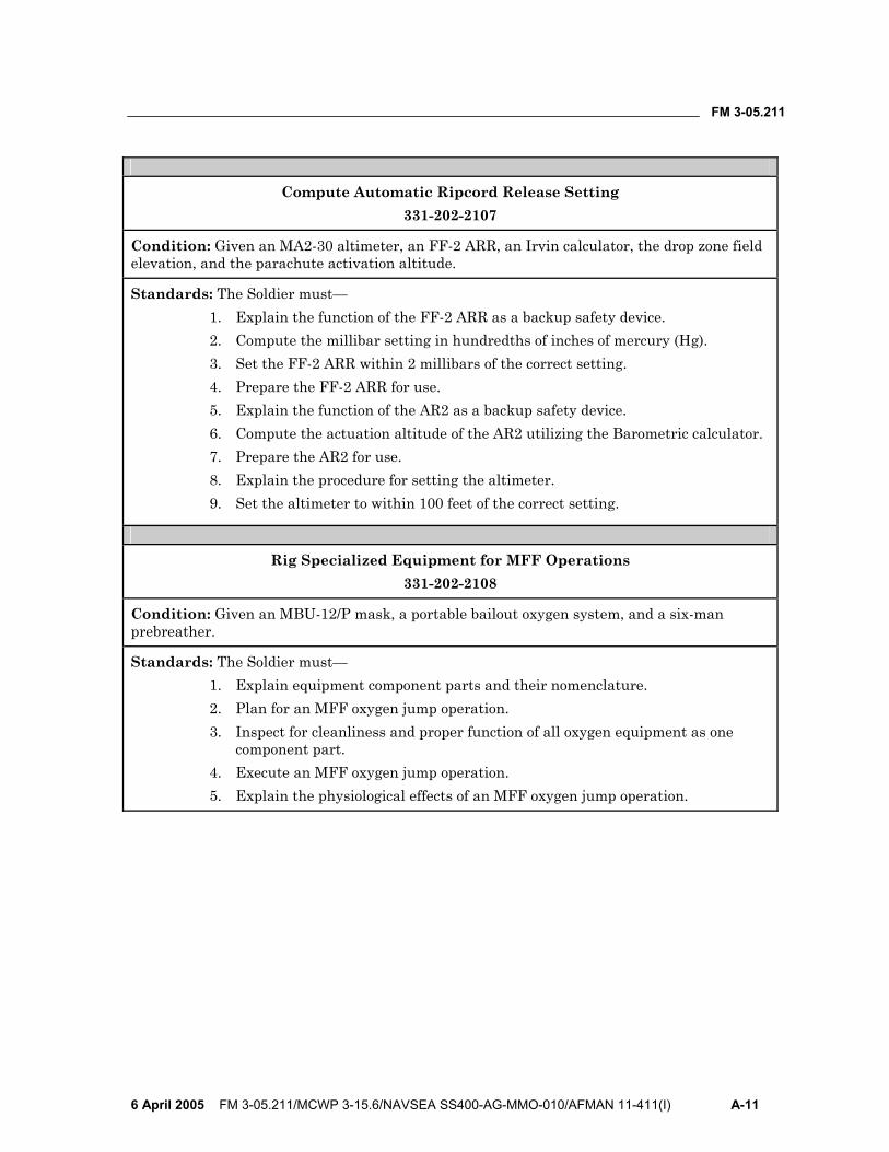
FM 3-05.211
6 April 2005 FM 3-05.211/MCWP 3-15.6/NAVSEA SS400-AG-MMO-010/AFMAN 11-411(I) A-11
Compute Automatic Ripcord Release Setting
331-202-2107
Condition: Given an MA2-30 altimeter, an FF-2 ARR, an Irvin calculator, the drop zone field elevation, and the parachute activation altitude.
Standards: The Soldier must— 1. Explain the function of the FF-2 ARR as a backup safety device. 2. Compute the millibar setting in hundredths of inches of mercury (Hg). 3. Set the FF-2 ARR within 2 millibars of the correct setting. 4. Prepare the FF-2 ARR for use. 5. Explain the function of the AR2 as a backup safety device. 6. Compute the actuation altitude of the AR2 utilizing the Barometric calculator. 7. Prepare the AR2 for use. 8. Explain the procedure for setting the altimeter.
9. Set the altimeter to within 100 feet of the correct setting.
Rig Specialized Equipment for MFF Operations
331-202-2108
Condition: Given an MBU-12/P mask, a portable bailout oxygen system, and a six-man prebreather.
Standards: The Soldier must— 1. Explain equipment component parts and their nomenclature. 2. Plan for an MFF oxygen jump operation. 3. Inspect for cleanliness and proper function of all oxygen equipment as one
component part. 4. Execute an MFF oxygen jump operation. 5. Explain the physiological effects of an MFF oxygen jump operation.
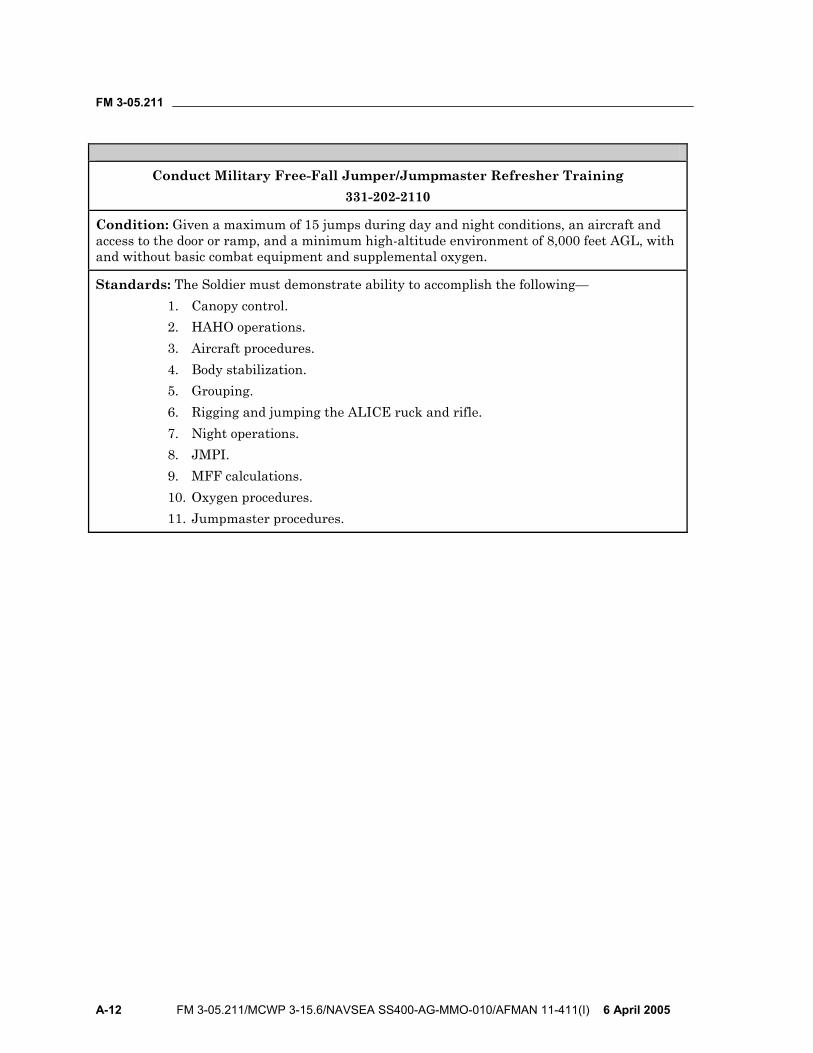
FM 3-05.211
A-12 FM 3-05.211/MCWP 3-15.6/NAVSEA SS400-AG-MMO-010/AFMAN 11-411(I) 6 April 2005
Conduct Military Free-Fall Jumper/Jumpmaster Refresher Training
331-202-2110
Condition: Given a maximum of 15 jumps during day and night conditions, an aircraft and access to the door or ramp, and a minimum high-altitude environment of 8,000 feet AGL, with and without basic combat equipment and supplemental oxygen.
Standards: The Soldier must demonstrate ability to accomplish the following— 1. Canopy control. 2. HAHO operations. 3. Aircraft procedures. 4. Body stabilization. 5. Grouping. 6. Rigging and jumping the ALICE ruck and rifle. 7. Night operations. 8. JMPI. 9. MFF calculations. 10. Oxygen procedures. 11. Jumpmaster procedures.
FM 3-05.211
6 April 2005 FM 3-05.211/MCWP 3-15.6/NAVSEA SS400-AG-MMO-010/AFMAN 11-411(I) B-1
Appendix B
Military Free-Fall Parachutist Qualification and Refresher Training Requirements
MFF parachuting skills are highly perishable. MFF personnel maintain these skills through regularly scheduled training periods to develop the necessary degree of proficiency. Otherwise, mission capability and parachutist safety will suffer.
MEDICAL AND PHYSIOLOGICAL TRAINING REQUIREMENTS
B-1 Each MFF parachutist must have met the following minimum requirements to participate in MFF operations:
• Must have a current HALO physical examination IAW Service regulations. Students attending the MFF course must have a HALO physical IAW the USAJFKSWCS standard.
• Must have a current physiological training card (AF Form 1274) dated within the last 5 years. A physiological training card is maintained by undergoing physiological training every 5 years.
• To conduct MFF operations, must be a graduate of a USAJFKSWCS-recognized MFF parachutist course.
• Must be a current MFF parachutist.
CURRENCY REQUIREMENTS B-2. Currency does not equate to proficiency. Parachutists cannot consider MFF airborne operations to meet pay requirements as proficiency jumps unless the mission profile follows a tactical insertion profile. MFF jumpmaster currency standards are outlined in Chapter 13. To meet the minimum MFF currency standards, the parachutist must have—
• A current HALO physical (per Service requirements). • A current USAF physiological training card (AF Form 702, Individual
Physiological Training Record, or AF Form 1274). • Conducted an MFF jump within the last 180 days.
MILITARY FREE-FALL PARACHUTE REQUALIFICATION AND REFRESHER TRAINING
B-3. Previously qualified MFF parachutists who, after meeting medical and USAF chamber currency requirements, do not meet the proficiency and
FM 3-05.211
B-2 FM 3-05.211/MCWP 3-15.6/NAVSEA SS400-AG-MMO-010/AFMAN 11-411(I) 6 April 2005
currency requirements listed above, will undergo the following training to become requalified:
• Attend emergency procedures class and suspended harness drills. • Attend combat equipment rigging (combat pack and weapon) class. • Attend canopy control and grouping under canopy class. • Perform one daylight jump without combat equipment, stressing a stable
exit, maintaining heading, and pulling the ripcord at the prescribed pull altitude while maintaining heading (plus or minus 500 feet).
• Perform one daylight jump with rifle and combat equipment, executing a stable exit, making a left and right turn, stopping on heading, and pulling the ripcord at the prescribed pull altitude (plus or minus 500 feet) while maintaining heading, and landing within 50 meters of the group leader.
• Perform one night jump with rifle, combat pack (rucksack), and complete oxygen system, executing a manual parachute activation at the prescribed pull altitude (plus or minus 500 feet), and landing within 50 meters of the group leader.
MILITARY FREE-FALL HIGH-ALTITUDE HIGH-OPENING PARACHUTIST REQUALIFICATION AND REFRESHER TRAINING
B-4. Previously qualified MFF parachutists who do not meet proficiency and currency requirements will, after becoming current as an MFF parachutist, undergo the training outlined below. The intent of the following recommendations is to build upon the training progression listed in the previous paragraphs. In addition, the intent is to provide safe training and increase parachutist skills, ability, and confidence, culminating in a HAHO night combat equipment oxygen jump. Recommendations include the parachutists make—
• One MFF ram-air parachute jump with combat equipment from not higher than 13,000 feet AGL with opening not lower than 10,000 feet AGL. They must land within 100 meters of the group leader.
• One MFF ram-air parachute jump with combat equipment and complete oxygen system with opening not higher than 18,000 feet AGL nor lower than 16,000 feet AGL. They must land within 100 meters of the group leader.
• A daylight combat equipment jump at altitudes above 18,000 feet MSL, depending upon the availability of USAF physiology technicians. For familiarization purposes, prebreathing can still take place below 18,000 feet MSL.
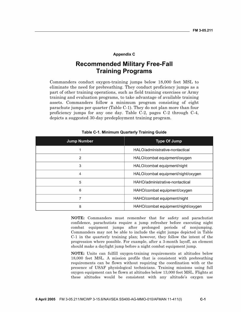
FM 3-05.211
6 April 2005 FM 3-05.211/MCWP 3-15.6/NAVSEA SS400-AG-MMO-010/AFMAN 11-411(I) C-1
Appendix C
Recommended Military Free-Fall Training Programs
Commanders conduct oxygen-training jumps below 18,000 feet MSL to eliminate the need for prebreathing. They conduct proficiency jumps as a part of other training operations, such as field training exercises or Army training and evaluation programs, to take advantage of available training assets. Commanders follow a minimum program consisting of eight parachute jumps per quarter (Table C-1). They do not plan more than four proficiency jumps for any one day. Table C-2, pages C-2 through C-4, depicts a suggested 30-day predeployment training program.
Table C-1. Minimum Quarterly Training Guide
NOTE: Commanders must remember that for safety and parachutist confidence, parachutists require a jump refresher before executing night combat equipment jumps after prolonged periods of nonjumping. Commanders may not be able to include the eight jumps depicted in Table C-1 in the quarterly training plan; however, they follow the intent of the progression where possible. For example, after a 3-month layoff, an element should make a daylight jump before a night combat equipment jump.
NOTE: Units can fulfill oxygen-training requirements at altitudes below 18,000 feet MSL. A mission profile that is consistent with prebreathing requirements can be flown without requiring the coordination with or the presence of USAF physiological technicians. Training missions using full oxygen equipment can be flown at altitudes below 13,000 feet MSL. Flights at these altitudes would be consistent with any altitude’s oxygen use
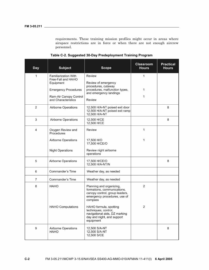
FM 3-05.211
C-2 FM 3-05.211/MCWP 3-15.6/NAVSEA SS400-AG-MMO-010/AFMAN 11-411(I) 6 April 2005
requirements. These training mission profiles might occur in areas where airspace restrictions are in force or when there are not enough aircrew personnel.
Table C-2. Suggested 30-Day Predeployment Training Program
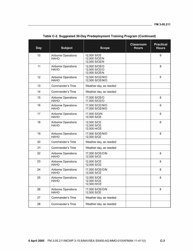
FM 3-05.211
6 April 2005 FM 3-05.211/MCWP 3-15.6/NAVSEA SS400-AG-MMO-010/AFMAN 11-411(I) C-3
Table C-2. Suggested 30-Day Predeployment Training Program (Continued)

FM 3-05.211
C-4 FM 3-05.211/MCWP 3-15.6/NAVSEA SS400-AG-MMO-010/AFMAN 11-411(I) 6 April 2005
Table C-2. Suggested 30-Day Predeployment Training Program (Continued)
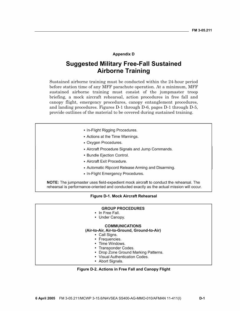
FM 3-05.211
6 April 2005 FM 3-05.211/MCWP 3-15.6/NAVSEA SS400-AG-MMO-010/AFMAN 11-411(I) D-1
Appendix D
Suggested Military Free-Fall Sustained Airborne Training
Sustained airborne training must be conducted within the 24-hour period before station time of any MFF parachute operation. At a minimum, MFF sustained airborne training must consist of the jumpmaster troop briefing, a mock aircraft rehearsal, action procedures in free fall and canopy flight, emergency procedures, canopy entanglement procedures, and landing procedures. Figures D-1 through D-6, pages D-1 through D-5, provide outlines of the material to be covered during sustained training.
Figure D-1. Mock Aircraft Rehearsal
Figure D-2. Actions in Free Fall and Canopy Flight
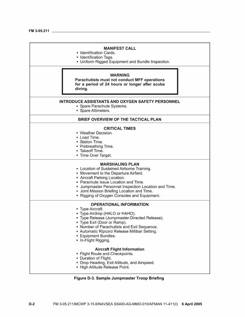
FM 3-05.211
D-2 FM 3-05.211/MCWP 3-15.6/NAVSEA SS400-AG-MMO-010/AFMAN 11-411(I) 6 April 2005
Figure D-3. Sample Jumpmaster Troop Briefing
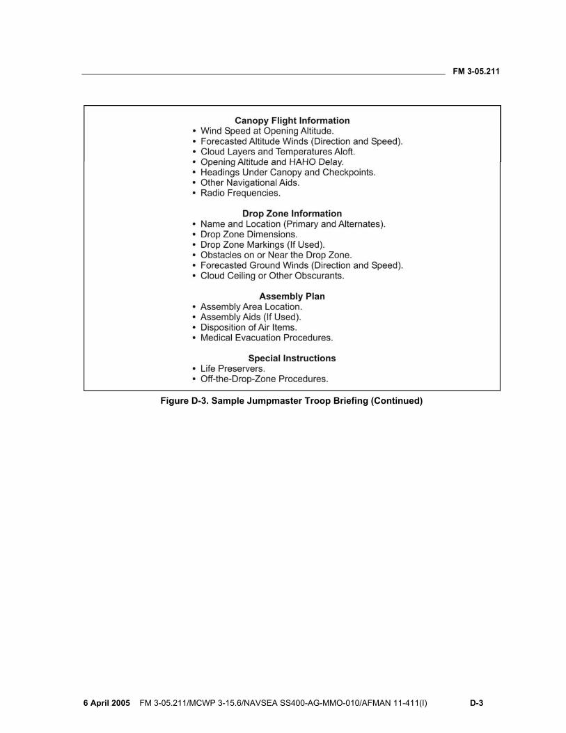
FM 3-05.211
6 April 2005 FM 3-05.211/MCWP 3-15.6/NAVSEA SS400-AG-MMO-010/AFMAN 11-411(I) D-3
Figure D-3. Sample Jumpmaster Troop Briefing (Continued)
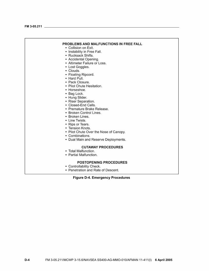
FM 3-05.211
D-4 FM 3-05.211/MCWP 3-15.6/NAVSEA SS400-AG-MMO-010/AFMAN 11-411(I) 6 April 2005
Figure D-4. Emergency Procedures
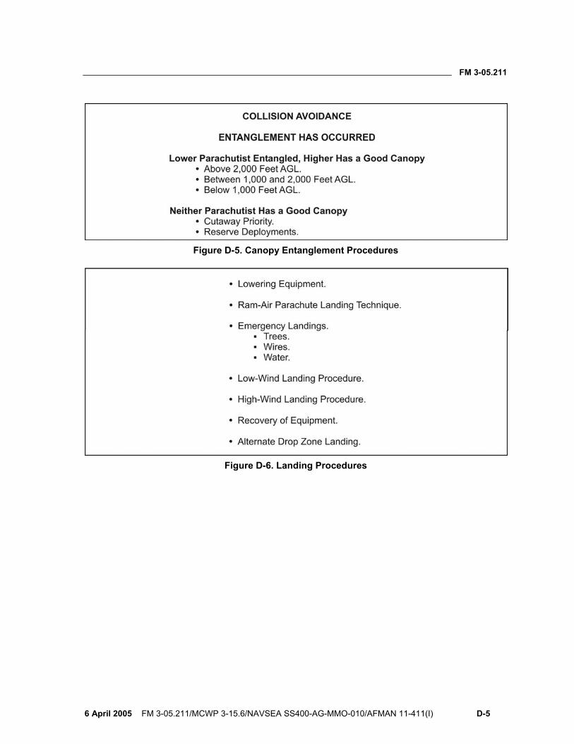
FM 3-05.211
6 April 2005 FM 3-05.211/MCWP 3-15.6/NAVSEA SS400-AG-MMO-010/AFMAN 11-411(I) D-5
Figure D-5. Canopy Entanglement Procedures
Figure D-6. Landing Procedures

This page intentionally left blank.
FM 3-05.211
6 April 2005 FM 3-05.211/MCWP 3-15.6/NAVSEA SS400-AG-MMO-010/AFMAN 11-411(I) E-1
Appendix E
Sample Accident Report This appendix provides a sample accident report at Figure E-1 (DA Form 285-AB-R, U.S. Army Abbreviated Ground Accident Report [AGAR]), pages E-2 and E-3. It provides an example of the amount of information that elements should provide in such reports.
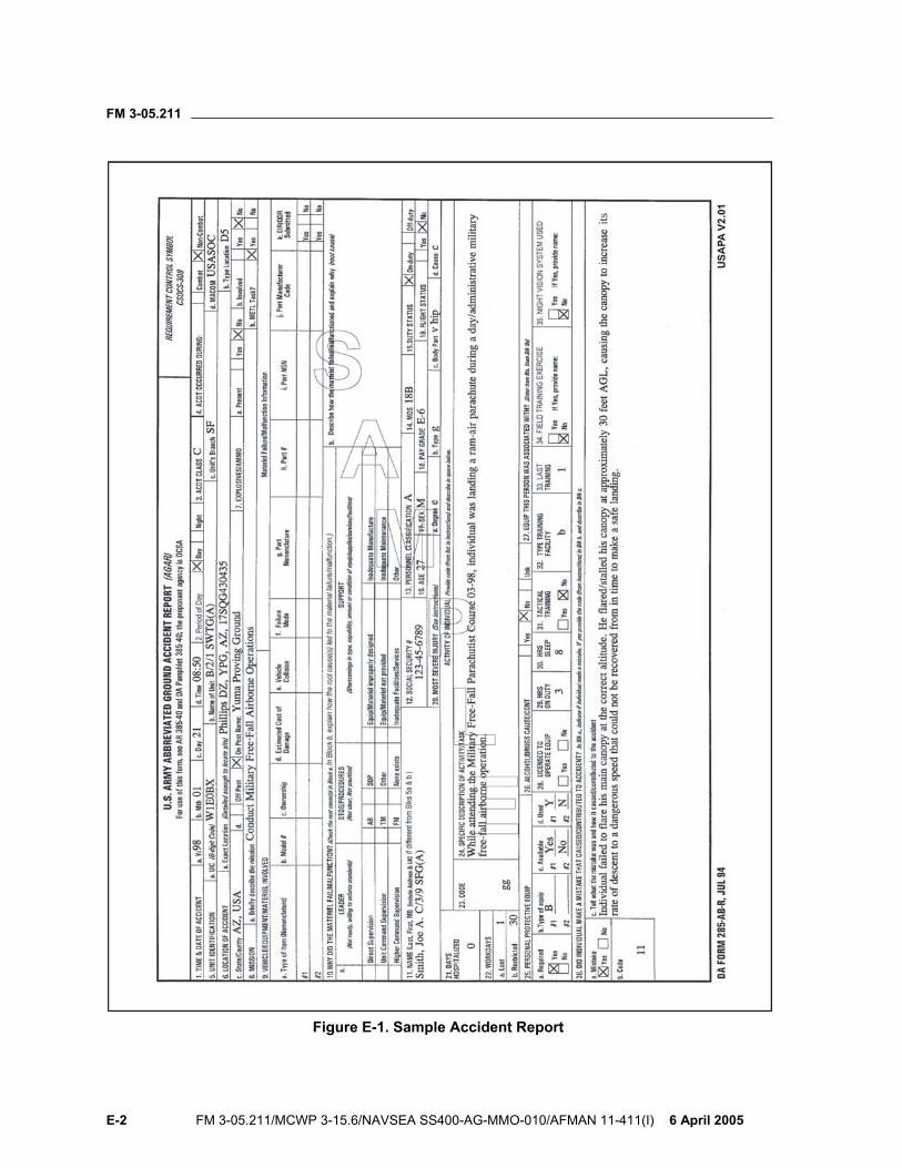
FM 3-05.211
E-2 FM 3-05.211/MCWP 3-15.6/NAVSEA SS400-AG-MMO-010/AFMAN 11-411(I) 6 April 2005
Figure E-1. Sample Accident Report
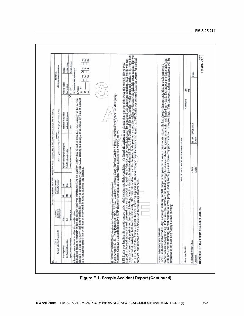
FM 3-05.211
6 April 2005 FM 3-05.211/MCWP 3-15.6/NAVSEA SS400-AG-MMO-010/AFMAN 11-411(I) E-3
Figure E-1. Sample Accident Report (Continued)

This page intentionally left blank.
FM 3-05.211
6 April 2005 FM 3-05.211/MCWP 3-15.6/NAVSEA SS400-AG-MMO-010/AFMAN 11-411(I) F-1
Appendix F
High-Altitude Release Point Calculation The effects of variable wind directions and speed must be accounted for when determining the HARP for each MFF mission. Accurate wind data is essential to calculate the HARP precisely. Commanders are cautioned against planning pinpoint landings on targets when wind data is questionable due to the source, timeliness of reporting, or other dynamic meteorological conditions (for example, thunderstorms or changing fronts). Wind will affect the parachutist during free fall and canopy performance after deployment.
OBTAINING WIND DATA F-1. Military airfields, civilian airports or weather services, artillery meteorological sections, or pilot teams in the operational areas can provide wind data. Aircrew personnel can also determine wind data during flight as the aircraft passes through different flight levels. (It is not advisable to use this technique for actual infiltrations, as the data obtained en route to the objective area may not reflect conditions at the objective area.)
RECORDING WIND DATA F-2. The jumpmaster records the reported wind data according to altitude in feet, direction in degrees, and speed (velocity) in knots. He records the wind data for every 2,000 feet of altitude during free fall and every 1,000 feet of altitude under canopy.
CALCULATING AND PLOTTING THE HARP F-3. The jumpmaster calculates and plots the HARP’s location in reverse sequence (Figure F-1, page F-2). First, he calculates the distance and direction from the DIP to the parachute opening point. Second, he calculates the distance and direction from the parachute opening point to the preliminary release point (PRP). Third, he calculates the distance and direction from the PRP (to compensate for forward throw) to the HARP.
F-4. Calculation of the HARP during HAHO operations may or may not require calculation of free-fall drift, depending upon the length of free fall required. For HAHO missions requiring less than 2,000 feet of free fall, the jumpmaster disregards free-fall drift.
F-5. When plotting the HARP on a map, the jumpmaster converts the wind direction from True North to a grid azimuth using the declination diagram.

FM 3-05.211
F-2 FM 3-05.211/MCWP 3-15.6/NAVSEA SS400-AG-MMO-010/AFMAN 11-411(I) 6 April 2005
Figure F-1. Plotting the HARP, Free-Fall, and Canopy Drift for a HALO Mission Profile
USING THE WIND DRIFT FORMULA AND CONSTANTS F-6. The jumpmaster uses the wind drift formula D = KAV.
• D = distance in meters. • K = constant (drift in meters per 1,000-foot loss of altitude in a 1-knot
wind). • A = altitude in thousands of feet. • V = average wind speed (velocity).
The jumpmaster also uses the following wind drift constants (K factors):
• K = 3 (parachutist in free fall). • K = 25 (MC-3 parachute system and RAPS [HALO]). • K = 48 (RAPS [HAHO]).
NOTE: The jumpmaster calculating the HAHO wind drift uses the constant of the least performing canopy; for example, the U.S. Navy MT1-X-S uses the S-type reserve that has a K factor of 60. Therefore, if a parachutist has to activate his reserve parachute, he will still be able to glide to the DZ.
FM 3-05.211
6 April 2005 FM 3-05.211/MCWP 3-15.6/NAVSEA SS400-AG-MMO-010/AFMAN 11-411(I) F-3
CALCULATING HALO FREE-FALL DRIFT AND DIRECTION F-7. To determine the parachutist’s drift in free fall, the jumpmaster calculates the average wind speed (velocity) and average wind direction from the exit to the opening altitude. Opening altitude (4,000 feet in this example) is not included since that is where the free fall stops. The wind data from 4,000 feet to 1,000 feet is calculated using the canopy drift constant.
EXAMPLE: Altitude Velocity Direction
20,000 85 160 18,000 75 160 16,000 75 165 14,000 65 165 12,000 50 155 10,000 45 150 8,000 20 185 6,000 20 190
485 knots 1330 degrees The jumpmaster determines the averages by—
• Determining the total free-fall distance from the exit (20,000) to the opening (4,000). A = 20,000 – 4,000 = 16,000, or A = 16.
• Dividing the sum of the wind velocities (435) by the number of velocities (8). V = 435 ÷ 8 = 54.375, or V = 54 (rounded to nearest whole number) knots average wind speed (velocity).
• Dividing the sum of the wind directions (1330) by the number of directions (8). Direction = 1330 ÷ 8 = 166.25, or Direction = 166 degrees (rounded to nearest whole number) average wind direction.
The jumpmaster substitutes the numerical values for the letters of the D = KAV formula.
• D = (3) (16) (54). • D = 2,592 meters at 166 degrees (True North).
NOTE: If using wind directions from 315 degrees to 045 degrees to calculate the average wind direction, incompatible averages may result. To compen-sate, the jumpmaster adds 360 degrees to directions of 001 to 045 degrees.
EXAMPLE: Direction Direction
345 345 350 350 345 345 010 010 (+360) = 370 015 015 (+360) = 375 350 350
1415 degrees 2135 degrees Direction = 1415 ÷ 6 = 235.83 or D = 236 degrees (incorrect).
Direction = 2135 ÷ 6 = 355.83 degrees or D = 356 degrees (correct).
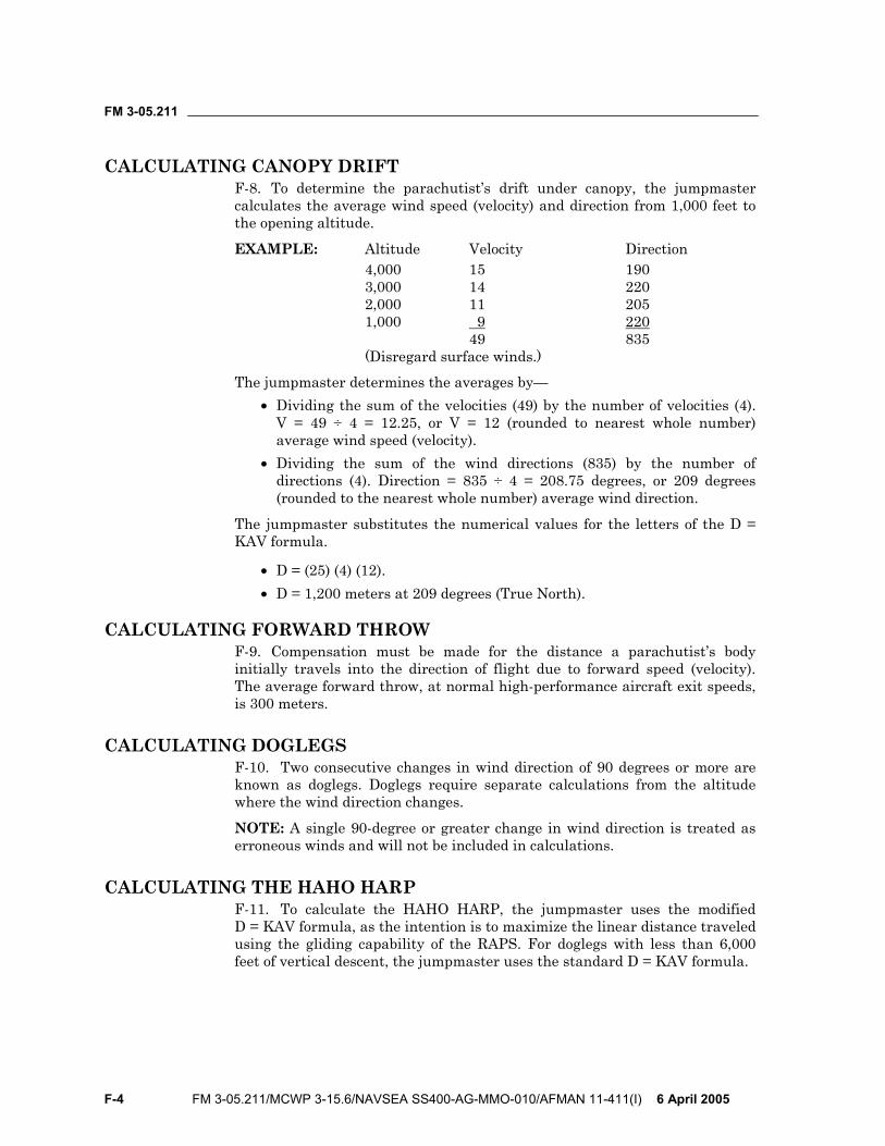
FM 3-05.211
F-4 FM 3-05.211/MCWP 3-15.6/NAVSEA SS400-AG-MMO-010/AFMAN 11-411(I) 6 April 2005
CALCULATING CANOPY DRIFT F-8. To determine the parachutist’s drift under canopy, the jumpmaster calculates the average wind speed (velocity) and direction from 1,000 feet to the opening altitude.
EXAMPLE: Altitude Velocity Direction 4,000 15 190 3,000 14 220 2,000 11 205 1,000 9 220
49 835 (Disregard surface winds.)
The jumpmaster determines the averages by— • Dividing the sum of the velocities (49) by the number of velocities (4).
V = 49 ÷ 4 = 12.25, or V = 12 (rounded to nearest whole number) average wind speed (velocity).
• Dividing the sum of the wind directions (835) by the number of directions (4). Direction = 835 ÷ 4 = 208.75 degrees, or 209 degrees (rounded to the nearest whole number) average wind direction.
The jumpmaster substitutes the numerical values for the letters of the D = KAV formula.
• D = (25) (4) (12). • D = 1,200 meters at 209 degrees (True North).
CALCULATING FORWARD THROW F-9. Compensation must be made for the distance a parachutist’s body initially travels into the direction of flight due to forward speed (velocity). The average forward throw, at normal high-performance aircraft exit speeds, is 300 meters.
CALCULATING DOGLEGS F-10. Two consecutive changes in wind direction of 90 degrees or more are known as doglegs. Doglegs require separate calculations from the altitude where the wind direction changes.
NOTE: A single 90-degree or greater change in wind direction is treated as erroneous winds and will not be included in calculations.
CALCULATING THE HAHO HARP F-11. To calculate the HAHO HARP, the jumpmaster uses the modified D = KAV formula, as the intention is to maximize the linear distance traveled using the gliding capability of the RAPS. For doglegs with less than 6,000 feet of vertical descent, the jumpmaster uses the standard D = KAV formula.
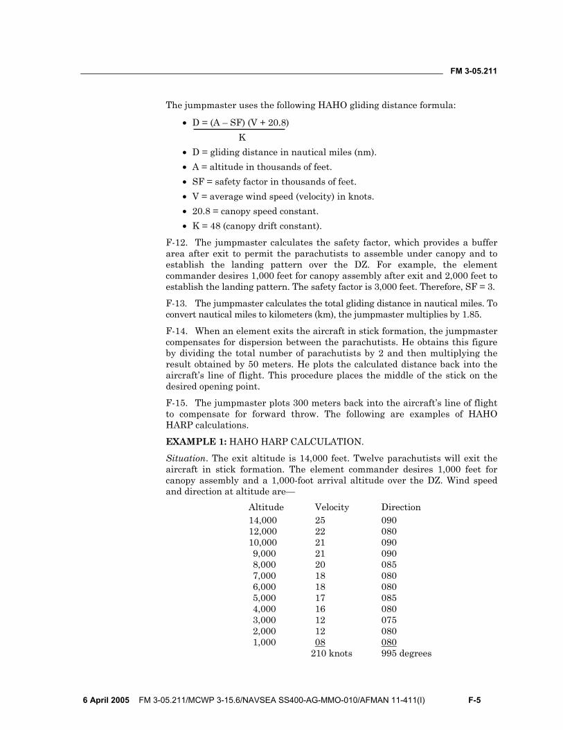
FM 3-05.211
6 April 2005 FM 3-05.211/MCWP 3-15.6/NAVSEA SS400-AG-MMO-010/AFMAN 11-411(I) F-5
The jumpmaster uses the following HAHO gliding distance formula:
• D = (A – SF) (V + 20.8) K
• D = gliding distance in nautical miles (nm). • A = altitude in thousands of feet. • SF = safety factor in thousands of feet. • V = average wind speed (velocity) in knots. • 20.8 = canopy speed constant. • K = 48 (canopy drift constant).
F-12. The jumpmaster calculates the safety factor, which provides a buffer area after exit to permit the parachutists to assemble under canopy and to establish the landing pattern over the DZ. For example, the element commander desires 1,000 feet for canopy assembly after exit and 2,000 feet to establish the landing pattern. The safety factor is 3,000 feet. Therefore, SF = 3.
F-13. The jumpmaster calculates the total gliding distance in nautical miles. To convert nautical miles to kilometers (km), the jumpmaster multiplies by 1.85.
F-14. When an element exits the aircraft in stick formation, the jumpmaster compensates for dispersion between the parachutists. He obtains this figure by dividing the total number of parachutists by 2 and then multiplying the result obtained by 50 meters. He plots the calculated distance back into the aircraft’s line of flight. This procedure places the middle of the stick on the desired opening point.
F-15. The jumpmaster plots 300 meters back into the aircraft’s line of flight to compensate for forward throw. The following are examples of HAHO HARP calculations.
EXAMPLE 1: HAHO HARP CALCULATION.
Situation. The exit altitude is 14,000 feet. Twelve parachutists will exit the aircraft in stick formation. The element commander desires 1,000 feet for canopy assembly and a 1,000-foot arrival altitude over the DZ. Wind speed and direction at altitude are— Altitude Velocity Direction
14,000 25 090 12,000 22 080 10,000 21 090 9,000 21 090 8,000 20 085 7,000 18 080 6,000 18 080 5,000 17 085 4,000 16 080 3,000 12 075 2,000 12 080 1,000 08 080
210 knots 995 degrees

FM 3-05.211
F-6 FM 3-05.211/MCWP 3-15.6/NAVSEA SS400-AG-MMO-010/AFMAN 11-411(I) 6 April 2005
F-16. The jumpmaster—
• Determines the average wind speed: V = 210 ÷ 12 = 17.50, or V = 18 (rounded to nearest whole number) average wind speed.
• Determines the average wind direction: D = 995 ÷ 12 = 82.91, or D = 83 (rounded to nearest whole number) degrees (True North) average wind direction.
• Determines the safety factor is 2 (minimum). • Substitutes the numerical values for the letters of the formula:
D = (12 – 2) (20.8 + 18) ÷ 48. D = (10) (38.8) ÷ 48. D = 388.0 ÷ 48. D = 8.0 nm at 83 degrees (True North).
• Determines the gliding distance: 8.0 nm x 1.85 = 14.80 km. • Determines dispersion: (12 ÷ 2) x 50 = 300 meters. • Determines forward throw: 300 meters. • Converts the average wind direction to a grid azimuth and plots it on
the map to determine the opening point. • Plots the dispersion and forward throw from the PRP to determine the
HARP (there is no free-fall drift in a HAHO, so the PRP is the opening point).
• Determines the grid azimuth from the opening point to the DIP. Converts the grid azimuth to a magnetic azimuth. The magnetic azimuth is the compass heading followed to the DZ.
EXAMPLE 2: HAHO HARP CALCULATION WITH A DOGLEG.
Situation. Exit altitude is 15,000 feet. Twelve parachutists exit the aircraft in stick formation. The element commander desires 1,000 feet for canopy assembly and a 2,000-foot arrival altitude over the DZ. A change of wind direction creates a dogleg at 9,000 feet AGL. Wind speed and direction at altitude are—
Altitude Velocity Direction 14,000 33 210 12,000 30 210 10,000 29 180
92 knots 600 degrees 9,000 26 075 8,000 24 080 7,000 22 085 6,000 20 090 5,000 18 090 4,000 14 085 3,000 12 090 2,000 10 085 1,000 8 080
154 knots 760 degrees
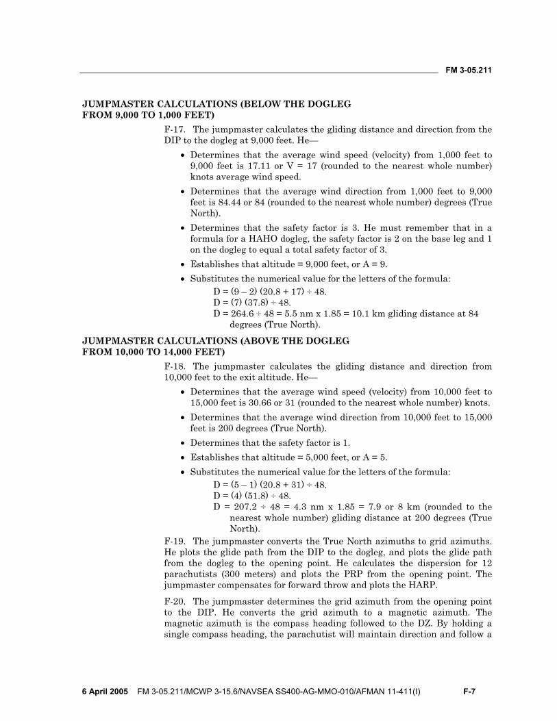
FM 3-05.211
6 April 2005 FM 3-05.211/MCWP 3-15.6/NAVSEA SS400-AG-MMO-010/AFMAN 11-411(I) F-7
JUMPMASTER CALCULATIONS (BELOW THE DOGLEG FROM 9,000 TO 1,000 FEET)
F-17. The jumpmaster calculates the gliding distance and direction from the DIP to the dogleg at 9,000 feet. He—
• Determines that the average wind speed (velocity) from 1,000 feet to 9,000 feet is 17.11 or V = 17 (rounded to the nearest whole number) knots average wind speed.
• Determines that the average wind direction from 1,000 feet to 9,000 feet is 84.44 or 84 (rounded to the nearest whole number) degrees (True North).
• Determines that the safety factor is 3. He must remember that in a formula for a HAHO dogleg, the safety factor is 2 on the base leg and 1 on the dogleg to equal a total safety factor of 3.
• Establishes that altitude = 9,000 feet, or A = 9. • Substitutes the numerical value for the letters of the formula:
D = (9 – 2) (20.8 + 17) ÷ 48. D = (7) (37.8) ÷ 48. D = 264.6 ÷ 48 = 5.5 nm x 1.85 = 10.1 km gliding distance at 84
degrees (True North).
JUMPMASTER CALCULATIONS (ABOVE THE DOGLEG FROM 10,000 TO 14,000 FEET)
F-18. The jumpmaster calculates the gliding distance and direction from 10,000 feet to the exit altitude. He—
• Determines that the average wind speed (velocity) from 10,000 feet to 15,000 feet is 30.66 or 31 (rounded to the nearest whole number) knots.
• Determines that the average wind direction from 10,000 feet to 15,000 feet is 200 degrees (True North).
• Determines that the safety factor is 1. • Establishes that altitude = 5,000 feet, or A = 5. • Substitutes the numerical value for the letters of the formula:
D = (5 – 1) (20.8 + 31) ÷ 48. D = (4) (51.8) ÷ 48. D = 207.2 ÷ 48 = 4.3 nm x 1.85 = 7.9 or 8 km (rounded to the
nearest whole number) gliding distance at 200 degrees (True North).
F-19. The jumpmaster converts the True North azimuths to grid azimuths. He plots the glide path from the DIP to the dogleg, and plots the glide path from the dogleg to the opening point. He calculates the dispersion for 12 parachutists (300 meters) and plots the PRP from the opening point. The jumpmaster compensates for forward throw and plots the HARP.
F-20. The jumpmaster determines the grid azimuth from the opening point to the DIP. He converts the grid azimuth to a magnetic azimuth. The magnetic azimuth is the compass heading followed to the DZ. By holding a single compass heading, the parachutist will maintain direction and follow a
FM 3-05.211
F-8 FM 3-05.211/MCWP 3-15.6/NAVSEA SS400-AG-MMO-010/AFMAN 11-411(I) 6 April 2005
curving path from the opening point to the DZ, rather than a path with distinct turns.
NOTE: The safety factor above the dogleg and below the dogleg, when combined, mathematically incorporates the desired effect over the complete group.
FM 3-05.211
6 April 2005 FM 3-05.211/MCWP 3-15.6/NAVSEA SS400-AG-MMO-010/AFMAN 11-411(I) G-1
Appendix G
Jumpmaster Personnel Inspection Before each MFF parachute operation, the jumpmaster conducts a systematic inspection of each parachutist’s parachute and combat equipment for proper wear, fit, and attachment. All equipment being airdropped will receive a JMPI. The jumpmaster must never sacrifice safety for speed.
DANGER Improper or incomplete jumpmaster personnel inspections may result in death, serious injury, or equipment loss and damage.
JMPI OF THE MC-4 HARNESS AND CONTAINER SYSTEM G-1. The jumpmaster uses the following sequence to detect and identify deficiencies. With hands and eyes working together, he starts at the front of the parachutist and moves to the rear, from top to bottom, right side to left side (Figure G-1, page G-2).
NOTE: If making an oxygen jump, the jumpmaster first performs the oxygen inspection sequence on page G-11. Then he continues with the following:
NOTE: If jumping in the vicinity of a water hazard, the jumpmaster follows the inspection sequence for flotation devices on page G-14. Then he continues with the following:
• Harness: Checks for proper fit before continuing the JMPI. • Helmet and goggles:
Uses correct helmet: MC-3, Gentex HGU-55/P, Gentex lightweight parachutist helmet, Bell helmet, or Protec helmet with free-fall liner.
Makes sure it fits properly and is serviceable. Uses approved goggles (Kroop; military-issue sun, wind, and dust
goggles; or Gentex only). Makes sure the lenses are clear and not cracked or scratched. Makes sure the goggle strap is secured if worn outside of helmet. Checks that bayonet receivers are present and securely attached. Makes sure the two adjustment screws are present on the receiver
covers. Checks chin strap for proper attachment and serviceability, with
excess stowed. Right riser: Makes sure no twists are present in front or rear riser
from riser cover to 3-ring release assembly.
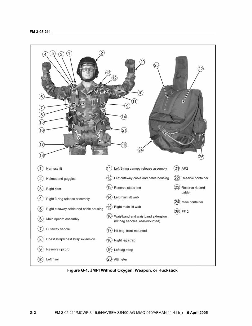
FM 3-05.211
G-2 FM 3-05.211/MCWP 3-15.6/NAVSEA SS400-AG-MMO-010/AFMAN 11-411(I) 6 April 2005
Figure G-1. JMPI Without Oxygen, Weapon, or Rucksack
FM 3-05.211
6 April 2005 FM 3-05.211/MCWP 3-15.6/NAVSEA SS400-AG-MMO-010/AFMAN 11-411(I) G-3
• Right 3-ring release assembly: Checks for correct assembly—small ring, medium ring, and base
ring (elongated snowman effect). Gives small and medium ring a one-quarter turn to check for free
movement. • Right main canopy release cable and cable housing:
Inspects for tacking and proper routing. Makes sure the 3-ring locking loop is through the small ring and
the grommet on the riser and the eye on the cable housing (without any twists or frays).
Rotates riser toward the parachutist’s neck, ensuring the release cable is routed through the locking loop and the running end is stowed in the stowage flute.
• Main ripcord assembly: Makes sure the housing is tacked properly. Makes sure there are no broken strands on main ripcord cable. Makes sure the two swage balls are present on the end of the
ripcord cable. Checks that the main ripcord handle is properly seated in the
elastic pocket. • Cutaway handle (main canopy release ripcord):
Makes sure that the cutaway cables are not twisted more than 180 degrees.
Checks that the handle is seated in its pocket and the Velcro is properly mated.
• Chest strap: Makes sure there are no twists and it is properly routed (to include
the chest strap extension). Makes sure the excess is rolled under and stowed in the slack
retainer. Makes sure it is properly routed through the friction adapter.
NOTE: If jumping with a weapon, jumpmaster follows the inspection sequence on page G-14. Then he continues with the following:
• Reserve ripcord: Makes sure it is properly seated in the elastic pocket. Checks that the two swage balls are present on end of the reserve
ripcord cable. Makes sure there are no broken strands. Makes sure the cable is properly routed to the cable housing. Makes sure the cable housing is tacked.
• Left riser: Makes sure there are no twists in the front or rear riser from the riser cover to the 3-ring release assembly.
FM 3-05.211
G-4 FM 3-05.211/MCWP 3-15.6/NAVSEA SS400-AG-MMO-010/AFMAN 11-411(I) 6 April 2005
• Left 3-ring release assembly: Checks for correct assembly—small ring, medium ring, and base
ring (elongated snowman effect). Gives the small and medium rings a one-quarter turn to check for
free movement. • Left main canopy release cable and cable housing:
Inspects for tacking and proper routing. Makes sure the 3-ring locking loop is through the small ring and
the grommet on the riser and the eye on the cable housing (without any twists or frays).
Rotates riser toward parachutist’s neck, making sure the release cable is routed through the locking loop and the running end is stowed in the stowage flute.
• Reserve static line: Makes sure the reserve static-line quick-release lanyard is
attached and snapped. Makes sure the reserve static-line loop is attached to the release
shackle and routed correctly. • Left main lift web:
Checks that the large equipment attachment ring and V-ring are present.
Makes sure the running end of the adjustment strap is rolled and stowed in the slack retainer.
Makes sure there are no twists.
NOTE: If jumping with a rucksack, jumpmaster follows the inspection sequence on page G-16. Then he continues with the following:
• Right main lift web: Checks that the large equipment attachment ring and V-ring are
present. Makes sure the running end of the adjustment strap is rolled and
stowed in the slack retainer. Makes sure there are no twists. Checks free-floating strap and oxygen fitting block for proper
attachment, and makes sure the four screws are present on the back of the fitting block.
• Waistband, waistband extension, and kit bag handles (rear-mounted): Makes sure the right wing flap is secured to the waistband. Checks that there are no twists from its attachment point on the
right side of container to the left wing flap. Makes sure the excess is rolled under and stowed in the slack
retainer.
FM 3-05.211
6 April 2005 FM 3-05.211/MCWP 3-15.6/NAVSEA SS400-AG-MMO-010/AFMAN 11-411(I) G-5
Checks for proper routing through the waistband extension friction adapter.
Checks the waistband extension is routed through the kit bag handles (rear-mounted).
Checks the kit bag is positioned between the jumper’s back and the main pack tray.
• Right leg strap, kit bag handle (front-mounted): Makes sure the snap hook gate closes and has proper spring
tension. Makes sure the excess is rolled under and stowed in the slack
retainer. Checks for correct routing, with no twist in leg strap or saddle. Ensures the leg strap is routed through one kit bag carrying handle
(front-mounted). • Left leg strap, kit bag handle (front-mounted):
Makes sure the snap hook gate closes and has proper spring tension.
Makes sure the excess is rolled under and stowed in the slack retainer.
Checks for correct routing, with no twist in leg strap or saddle. Ensures the leg strap is routed through one kit bag carrying handle
(front-mounted). • Altimeter, MA2-30:
Makes sure it is located on parachutist’s left wrist, that it fits snugly, and it is properly attached (with 0 to the top).
Checks for proper free-fall altimeter setting. Tells the parachutist to turn and continue the JMPI.
• Reserve container: Peels open the reserve ripcord protective flap. Makes sure the reserve ripcord cable housing is tacked down. Checks that the reserve static line is routed correctly, and that the
reserve ripcord cable runs through the reserve static-line ring and fixed guide ring.
• Reserve ripcord cable: Checks that the reserve ripcord cable has no broken strands. Makes sure it is routed on the left side of the grommets. Makes sure the top pin is inserted at a 45-degree angle. Makes sure the closing loops are not frayed.
FM 3-05.211
G-6 FM 3-05.211/MCWP 3-15.6/NAVSEA SS400-AG-MMO-010/AFMAN 11-411(I) 6 April 2005
Makes sure both pins are not seated past their shoulders. Tells the parachutist to bend.
• Main container: Opens both protective flaps. Makes sure the closing flaps are closed in the proper sequence
(bottom, left, right, top). Makes sure the main ripcord cable housing is tacked. Checks that main ripcord cable and ARR power cable are not
twisted around each other. Makes sure the 2-inch cable extension with swage ball is at the
12 o’clock position (top). Makes sure the closing loop is not frayed. Makes sure the main pin is not seated past its shoulder.
• The AR2: Jumpmaster does the normal JMPI sequence through the inspection of the parachutist’s altimeter. After the altimeter inspection, the jumpmaster continues with the following:
Visually inspects the aneroid leak indicator for proper ambient altitude according to MSL elevation.
Ensures aneroid leak indicator window is not damaged. Moves the JUMP/OFF switch to the JUMP position, ensuring that
the activation lever has spring tension. Moves the JUMP/OFF switch to the OFF position. Ensures the lower protector flap of the AR2 pocket is snapped and
secured. Opens the top protector flap of the AR2 pocket and inspects the
altitude dial for proper setting. Closes the top protector flap. Ensures the power cable housing retainer is finger-tight with no
threads showing. Visually inspects to make sure the swage ball is not visible and
that the plastic seal retainer is present. Inspects the remainder of the power cable housing for visible
damage. Opens the reserve ripcord protector flap.
NOTE: Inspection procedures for the reserve-mounted AR2 differ from this point forward and are located on page G-7. Ensures the reserve ripcord cable is routed correctly through the
(first) reserve static-line assist ring and (second) fixed guide ring. Ensures the reserve ripcord handle has no broken strands. Makes sure the reserve ripcord handle is routed on the left side of
the grommets. Ensures the reserve ripcord locking pin is inserted at a 45-degree
angle.
FM 3-05.211
6 April 2005 FM 3-05.211/MCWP 3-15.6/NAVSEA SS400-AG-MMO-010/AFMAN 11-411(I) G-7
Ensures the reserve ripcord top locking pin is not shouldered or bent.
Makes sure the continuous reserve top-closing loop is not frayed. Ensures the reserve cable has no broken strands. Ensures the reserve ripcord bottom-locking pin is not shouldered or
bent. Makes sure the continuous reserve bottom-closing loop is not
frayed. Opens the power cable protective flap and the two-part main
parachute protective flap. Makes sure the main parachute closing flaps are closed in
sequence. Makes sure the main ripcord cable housing is tacked. Ensures the main ripcord cable is properly routed and has no
broken strands. Ensures the 2-inch cable extension with swage ball has no broken
strands and is routed above the main locking pin. Makes sure the main ripcord cable single-locking pin is not
shouldered or bent. Makes sure the main closing loop is not frayed. Ensures the main locking pin is routed through the power cable
eyelet. Ensures the power cable eyelet is to the right of the main closing
loop. Ensures the power cable eyelet is not in the grommet, and the
beveled edge of the eyelet is in direction of pull (toward mounting bracket).
Ensures the AR2 power cable is properly mounted from the eyelet to the mounting bracket and has no broken strands.
Ensures the AR2 mounting bracket screws are present and tight. Checks that the AR2 power cable housing is properly secured in the
power cable protective flap. Picks up the inspection as the reserve ripcord cable routes through
the reserve static-line guide ring and fixed guide ring. Continues the normal JMPI sequence from this point through completion, excluding any FF2-related item.
AND
• The AR2 (Reserve-Mounted): Jumpmaster does the normal JMPI sequence through the inspection of the power cable housing. After opening the reserve ripcord protector flap, the jumpmaster continues with the following:
Finds the two screws of the power cable housing mounting bracket, and gives the bracket a shake to ensure it is secured in place.
FM 3-05.211
G-8 FM 3-05.211/MCWP 3-15.6/NAVSEA SS400-AG-MMO-010/AFMAN 11-411(I) 6 April 2005
Traces the power cable as it protrudes from the cable housing, inspecting for proper routing and no broken strands.
Ensures the power cable eye is to the left of the grommet, not inside the grommet, and the beveled edge is up.
Inspects the reserve ripcord cable for proper routing and no broken strands.
Checks the routing of the reserve ripcord cable to ensure it runs through the assist ring (little ring) of the RSL and then through the guide ring (big ring).
Continues to inspect the reserve ripcord cable for proper routing and no broken strands until coming to the top reserve locking pin.
At the top reserve locking pin, ensures the cable is to the right of the grommet.
Inspects the pin to make sure it is not shouldered inside the grommet and the pin is not bent.
Makes sure the continuous closing loop of the reserve is not frayed. Continues inspecting down the cable to the bottom locking pin,
ensuring it is properly routed and there are no broken strands. At the bottom reserve locking pin, inspects the pin to make sure it
is not shouldered inside the grommet and the pin is not bent. Makes sure the continuous closing loop of the reserve is not frayed. Instructs the parachutist to bend. Opens up and pins the top protector flap of the main parachute
with the left hand while opening the FF-2 protector flap with the right hand.
Makes sure the closing flaps are closed in the proper sequence (bottom, left, right, top).
Makes sure the main ripcord cable housing is tacked. Ensures the main ripcord cable is properly routed and has no
broken strands. Ensures the 2-inch cable extension with swage ball is properly
routed and has no broken strands. Makes sure the main locking pin does not come loose and is not
shouldered or bent. Makes sure the main closing loop is not frayed. Slaps the bottom of the container to indicate completion of the
JMPI.
OR
• The FF-2: Makes sure the withdrawal hook is routed around the main ripcord
pin and to the right of the closing loop. Makes sure the withdrawal hook is not seated in the grommet.
FM 3-05.211
6 April 2005 FM 3-05.211/MCWP 3-15.6/NAVSEA SS400-AG-MMO-010/AFMAN 11-411(I) G-9
Makes sure the knurled nut is finger-tight and at least three threads are showing.
Makes sure the rubber bumper is present. Moves the rubber bumper to check that the FF-2 power cable has
no broken strands. Makes sure the locking key is properly seated and locked in the
stiffener plate. Tells the parachutist to stand erect. Follows the power cable housing forward to the knurled nut on the
body of the FF-2. Makes sure the knurled nut is finger-tight. Checks that the arming pin is properly seated and locked in place. Checks that the FF-2 is properly placed in its stow pocket and the
snap fasteners are secured. Checks for correct millibar setting. Checks reset indicator for proper alignment (no more than 50
percent off). Taps parachutist to indicate completion of JMPI.
OR
• The MK 2100: Jumpmaster does the normal JMPI sequence through the inspection of the parachutist’s altimeter. After the altimeter inspection, the jumpmaster continues with the following:
Goes to the parachutist’s left side. Makes sure the arming pin is seated into the altitude sensing
device and the lanyard is tied in a half hitch around the top restraining strap of the MK 2100 pocket.
WARNING Jumpmaster must ensure the lanyard is not tied in a half hitch around the MK 2100 cable.
Makes sure the cable from the altitude-sensing unit is connected and secured to the cable protruding from the left side of the container.
Makes sure the nuts on both cables are hand-tight and serviceable. Pushes the button on the top of the altitude-sensing unit and
makes sure the red circuitry light is lit. NOTE: Once the aircraft has taken off, the red light will not work.
Opens the reserve protective flap. Makes sure the ripcord housing is tacked. Picks up the inspection as the reserve ripcord cable routes through
the reserve static-line guide ring and fixed guide ring.

FM 3-05.211
G-10 FM 3-05.211/MCWP 3-15.6/NAVSEA SS400-AG-MMO-010/AFMAN 11-411(I) 6 April 2005
Makes sure the reserve ripcord cable moves freely in the cable housing.
Makes sure the reserve cable is routed to the left of the top grommet.
Makes sure the top ripcord pin is at a 45-degree angle inserted through the withdrawal cable eyelet.
Makes sure both ripcord pins are fully seated. Continues the normal JMPI sequence from this point through
completion excluding any FF-2-related item.
OR
• The CYPRES: Jumpmaster does the normal JMPI sequence through the inspection of the parachutist’s altimeter. After the altimeter inspection, the jumpmaster continues with the following:
Opens the reserve protector flap and pins it up and out of the way. Traces the control cable and inspects for any damage and proper
routing. Makes sure the control cable is properly routed through the
binding tape guide. Makes sure the binding tape is properly tacked to the reserve top-
closing flap. Makes sure the control unit is set at the proper default for the
current free-fall operation. Makes sure the control unit LED indicator light is not lit. Checks that the control unit digital readout screen shows the
proper altitude setting. Inspects the reserve ripcord cable for proper routing and no broken
strands. Makes sure the reserve ripcord cable runs through the assist ring
(little ring) of the RSL and then through the guide ring (big ring). At the top reserve locking pin, ensures the reserve ripcord cable is
to the right of the grommet. Inspects the pin to make sure it is not shouldered inside the
grommet and the pin is not bent. Makes sure the continuous CYPRES closing loop of the reserve is
not frayed. Continues to inspect the reserve ripcord cable to the bottom locking
pin, making sure it is properly routed and there are no broken strands.
At the bottom reserve locking pin, inspects the pin to make sure it is not shouldered inside the grommet and the pin is not bent.
Makes sure the continuous CYPRES closing loop of the reserve is not frayed.
FM 3-05.211
6 April 2005 FM 3-05.211/MCWP 3-15.6/NAVSEA SS400-AG-MMO-010/AFMAN 11-411(I) G-11
Opens up and pins the top protector flap of the main parachute and opens the FF-2 protector flap.
Makes sure the closing flaps are closed in the proper sequence (bottom, left, right, top).
Makes sure the main ripcord cable housing is tacked. Inspects the cable for proper routing and no broken strands. Continues past the locking pin and inspects the 2-inch extension
for proper routing and no broken strands. Ensures the 2-inch extension terminates with a single steel swage
ball. Pinches the swage ball to ensure the main locking pin does not
come loose. Inspects the pin to make sure it is not shouldered inside the
grommet and the pin is not bent. Makes sure the main closing loop is not frayed. Slaps the bottom of the container to indicate completion of the
JMPI.
JMPI FOR THE MC-4 RAPS WITH THE 106-CUBIC-INCH PORTABLE BAILOUT OXYGEN SYSTEM
G-2. The jumpmaster inspects the entire oxygen system before inspecting the harness/container system. The recommended inspection sequence for the MC-4 RAPS with the oxygen system follows (Figure G-2, page G-12):
• Inspects the inside of the mask, making sure there is no debris, the four self-sealing screws are present, the combination valve retainer is present, and the portion that matches with the parachutist’s face is not torn or damaged in any way that would cause the parachutist to have an improper seal or fit.
• Attaches the mask to the left side bayonet receiver. • Checks for proper fit and seal. Makes sure there is no damage to the
hard shell or soft shell portion of the mask. Makes sure the four capped tee nuts secure the four attaching straps to the hard shell portion of the mask, and the excess is either taped or tacked. Checks that the combination valve is of the correct type (green exhalation port flaps only), the delivery tube clamp is present and attached properly, and there is no damage to the delivery tube at its attachment point to the combination valve.
• Detaches the oxygen mask from the left side bayonet receiver. Inspects the oxygen mask delivery tube to make sure there is no damage (checks for holes, discoloration, or deterioration). Makes sure the delivery tube retainer is present and attached correctly. Checks that the elastic slack retainer is around the chest strap and that the Velcro is mated around the delivery tube.
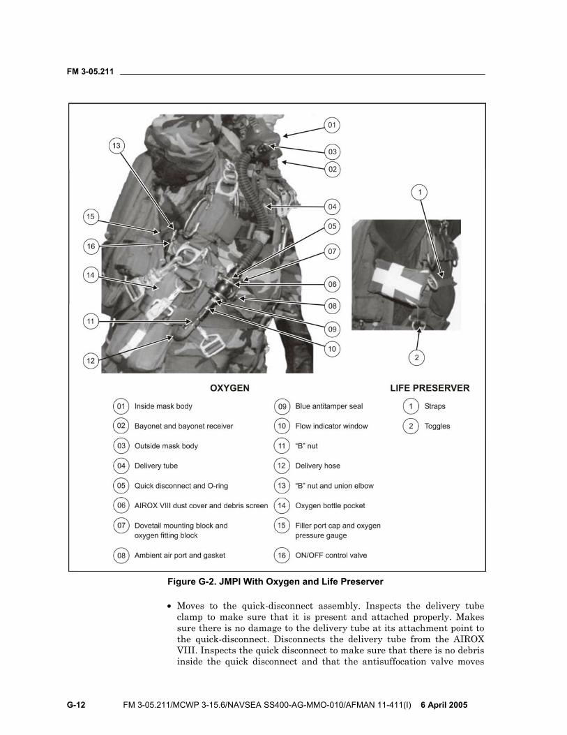
FM 3-05.211
G-12 FM 3-05.211/MCWP 3-15.6/NAVSEA SS400-AG-MMO-010/AFMAN 11-411(I) 6 April 2005
Figure G-2. JMPI With Oxygen and Life Preserver
• Moves to the quick-disconnect assembly. Inspects the delivery tube clamp to make sure that it is present and attached properly. Makes sure there is no damage to the delivery tube at its attachment point to the quick-disconnect. Disconnects the delivery tube from the AIROX VIII. Inspects the quick disconnect to make sure that there is no debris inside the quick disconnect and that the antisuffocation valve moves
FM 3-05.211
6 April 2005 FM 3-05.211/MCWP 3-15.6/NAVSEA SS400-AG-MMO-010/AFMAN 11-411(I) G-13
freely, has correct spring tension, and returns to the closed position. Inspects the gasket (O-ring) to make sure it is present and the beveled lip portion is up (not reversed).
• Inspects the AIROX VIII. Disconnects the oxygen mask delivery tube. Makes sure the dust cover is present and serviceable. Checks that the debris screen is present and is not damaged or corroded. Checks that there is no debris inside the AIROX VIII. Reconnects the oxygen mask delivery tube, making sure the quick-disconnect assembly is fully seated.
• Grasps the AIROX VIII and moves the entire assembly gently up and down to check that the dovetail mounting plate is correctly mated with the oxygen fitting block. Inspects the oxygen fitting block to make sure it is assembled correctly and the four attachment screws are present and secure on the back of the oxygen fitting block.
• Checks the ambient air port of the AIROX VIII. Visually inspects the inside of the ambient air port to make sure the debris screen is present and is not damaged or corroded. Checks that there is no debris inside the ambient air port. Inspects the antisuffocation valve to make sure it has correct spring tension and returns to the closed position. Inspects the gasket (O-ring) to make sure it is present and that the beveled lip portion is up (not reversed).
• Inspects the blue antitamper seal (blue dot of paint). Makes sure it is present and aligned.
• Grasps the “B” nut, giving it a slight turn to make sure it is tight. (The “B” nut attaches the delivery hose [medium pressure] to the AIROX VIII.)
• Follows the delivery hose (medium pressure) from its point of connection on the AIROX VIII and checks for proper routing. Makes sure the delivery hose is routed from the AIROX VIII over the outside of the waistband. Checks that the delivery hose then makes a 180-degree bend and runs under the waistband and between the parachutist's body and his right main lift web. Checks that it then runs to the union elbow.
• Checks the “B” nut at its point of attachment to the union elbow for tightness by giving it a slight twist. Then gives the union elbow a slight twist, checking for proper tightness to the reducer manifold.
• Pushes up on the bottom of the oxygen bottle pocket with the left hand while the right hand is on the manifold and pulls the bottles away from the parachutist’s body. Moves to the overpressure relief valve making sure it is seated by pushing in on the cap. While in this position with the oxygen bottles away from the parachutist’s body, inspects the waistband from its point of attachment on the container to the right wing flap friction adapter. Makes sure the waistband is not twisted and the waistband is routed through both of the center loops on the oxygen bottle pocket. Checks that the oxygen system is between the waistband and right wing flap.
• Tells the parachutist to bend. Inspects the filler port cap making sure it is present and finger tight. Checks that the oxygen pressure gauge indicates adequate pressure. The needle on the oxygen pressure gauge must be on the number 1 of 1800 psi or higher to be correct.
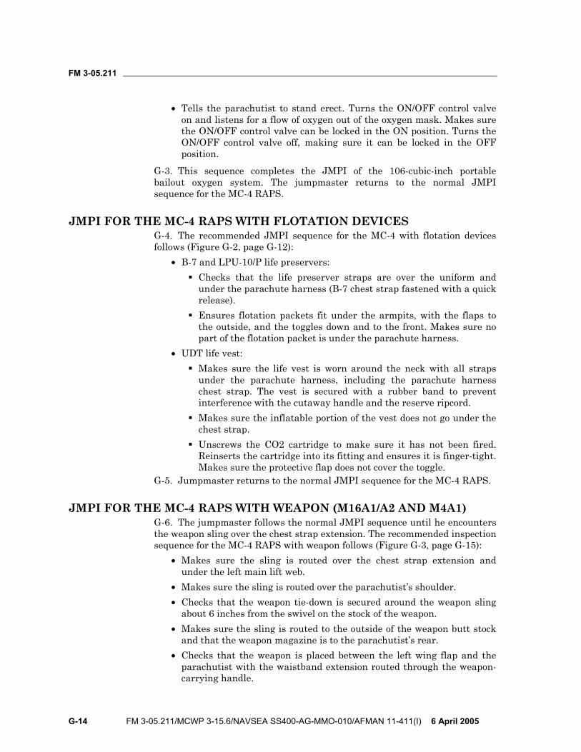
FM 3-05.211
G-14 FM 3-05.211/MCWP 3-15.6/NAVSEA SS400-AG-MMO-010/AFMAN 11-411(I) 6 April 2005
• Tells the parachutist to stand erect. Turns the ON/OFF control valve on and listens for a flow of oxygen out of the oxygen mask. Makes sure the ON/OFF control valve can be locked in the ON position. Turns the ON/OFF control valve off, making sure it can be locked in the OFF position.
G-3. This sequence completes the JMPI of the 106-cubic-inch portable bailout oxygen system. The jumpmaster returns to the normal JMPI sequence for the MC-4 RAPS.
JMPI FOR THE MC-4 RAPS WITH FLOTATION DEVICES G-4. The recommended JMPI sequence for the MC-4 with flotation devices follows (Figure G-2, page G-12):
• B-7 and LPU-10/P life preservers: Checks that the life preserver straps are over the uniform and
under the parachute harness (B-7 chest strap fastened with a quick release).
Ensures flotation packets fit under the armpits, with the flaps to the outside, and the toggles down and to the front. Makes sure no part of the flotation packet is under the parachute harness.
• UDT life vest: Makes sure the life vest is worn around the neck with all straps
under the parachute harness, including the parachute harness chest strap. The vest is secured with a rubber band to prevent interference with the cutaway handle and the reserve ripcord.
Makes sure the inflatable portion of the vest does not go under the chest strap.
Unscrews the CO2 cartridge to make sure it has not been fired. Reinserts the cartridge into its fitting and ensures it is finger-tight. Makes sure the protective flap does not cover the toggle.
G-5. Jumpmaster returns to the normal JMPI sequence for the MC-4 RAPS.
JMPI FOR THE MC-4 RAPS WITH WEAPON (M16A1/A2 AND M4A1) G-6. The jumpmaster follows the normal JMPI sequence until he encounters the weapon sling over the chest strap extension. The recommended inspection sequence for the MC-4 RAPS with weapon follows (Figure G-3, page G-15):
• Makes sure the sling is routed over the chest strap extension and under the left main lift web.
• Makes sure the sling is routed over the parachutist’s shoulder. • Checks that the weapon tie-down is secured around the weapon sling
about 6 inches from the swivel on the stock of the weapon. • Makes sure the sling is routed to the outside of the weapon butt stock
and that the weapon magazine is to the parachutist’s rear. • Checks that the weapon is placed between the left wing flap and the
parachutist with the waistband extension routed through the weapon-carrying handle.
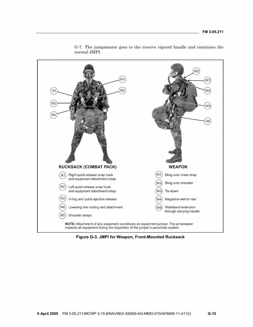
FM 3-05.211
6 April 2005 FM 3-05.211/MCWP 3-15.6/NAVSEA SS400-AG-MMO-010/AFMAN 11-411(I) G-15
G-7. The jumpmaster goes to the reserve ripcord handle and continues the normal JMPI.
Figure G-3. JMPI for Weapon, Front-Mounted Rucksack

FM 3-05.211
G-16 FM 3-05.211/MCWP 3-15.6/NAVSEA SS400-AG-MMO-010/AFMAN 11-411(I) 6 April 2005
JMPI FOR THE MC-4 RAPS WITH REAR- OR FRONT-MOUNTED COMBAT PACK (RUCKSACK)
G-8. The recommended inspection sequence for the MC-4 parachute assembly with the combat pack (rucksack) follows (Figures G-3, page G-15, front-mounted, and G-4, page G-17, rear-mounted). The jumpmaster follows the normal JMPI sequence until he arrives at the equipment attachment ring on the left main lift web. Then the jumpmaster—
• Makes sure the left quick-release snap hook has proper spring tension and that the gate is closed. Makes sure the quick-release is seated. Follows the left attachment strap around to the improved equipment attachment sling, making sure it is not routed under any portion of the MC-4 harness or rucksack frame.
• Makes sure the right quick-release snap hook has proper spring tension and that the gate is closed. Makes sure the quick-release is seated. Follows the right attachment strap around to the improved equipment attachment sling, making sure it is not routed under any portion of the MC-4 harness or rucksack frame.
• Inspects the HPT lowering line assembly at its point of attachment on the right V-ring. Makes sure the gate on the quick-ejector release is closed and that the locking arm is locked. Checks the routing of the tubular nylon to the nylon duck container (stow pocket), making sure it is routed free of any portion of the MC-4 parachute system or the rucksack frame and is located between the parachutist’s leg and the shoulder strap of the rucksack.
• Checks the running end of the HPT lowering line for proper attachment. Makes sure it is attached between the lateral locking straps where the diagonal straps cross. Checks that the running end of the lowering line passes through its own loop and is tightened down.
• Grasps both shoulder straps and pulls to the outside of the parachutist’s legs to make sure they are attached correctly and that the parachutist has a leg through each shoulder strap.
G-9. Jumpmaster returns to the JMPI inspection sequence at the left main lift web large equipment ring.
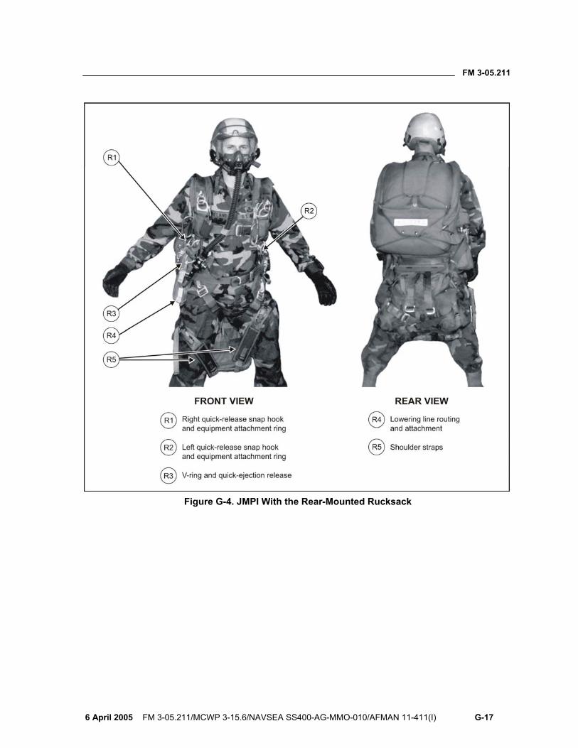
FM 3-05.211
6 April 2005 FM 3-05.211/MCWP 3-15.6/NAVSEA SS400-AG-MMO-010/AFMAN 11-411(I) G-17
Figure G-4. JMPI With the Rear-Mounted Rucksack

This page intentionally left blank.
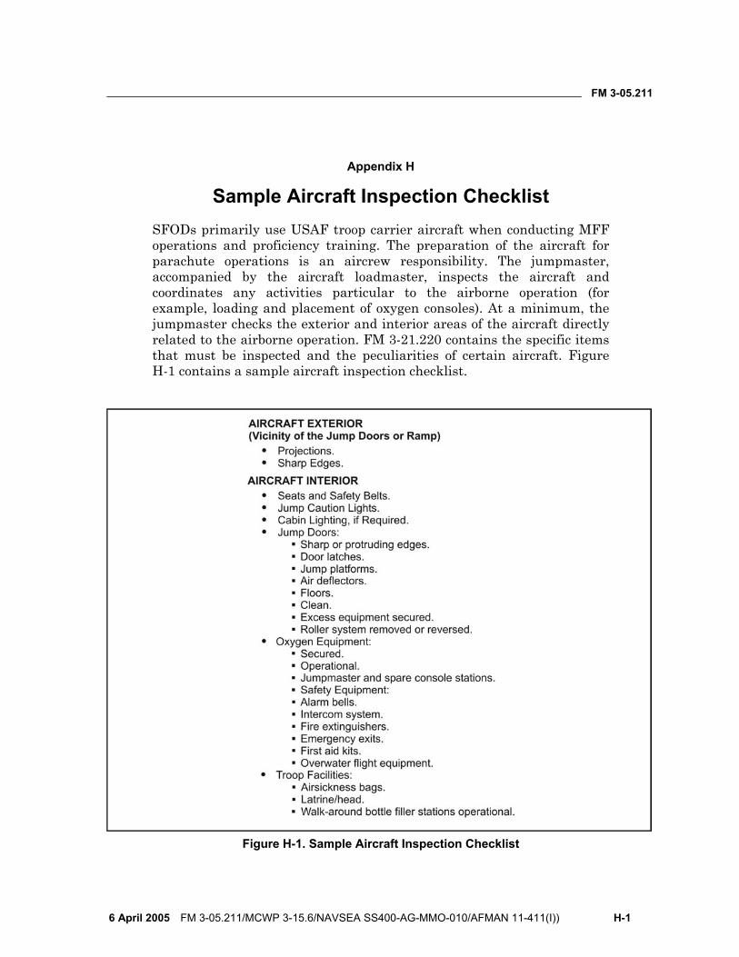
FM 3-05.211
6 April 2005 FM 3-05.211/MCWP 3-15.6/NAVSEA SS400-AG-MMO-010/AFMAN 11-411(I)) H-1
Appendix H
Sample Aircraft Inspection Checklist SFODs primarily use USAF troop carrier aircraft when conducting MFF operations and proficiency training. The preparation of the aircraft for parachute operations is an aircrew responsibility. The jumpmaster, accompanied by the aircraft loadmaster, inspects the aircraft and coordinates any activities particular to the airborne operation (for example, loading and placement of oxygen consoles). At a minimum, the jumpmaster checks the exterior and interior areas of the aircraft directly related to the airborne operation. FM 3-21.220 contains the specific items that must be inspected and the peculiarities of certain aircraft. Figure H-1 contains a sample aircraft inspection checklist.
Figure H-1. Sample Aircraft Inspection Checklist

This page intentionally left blank.
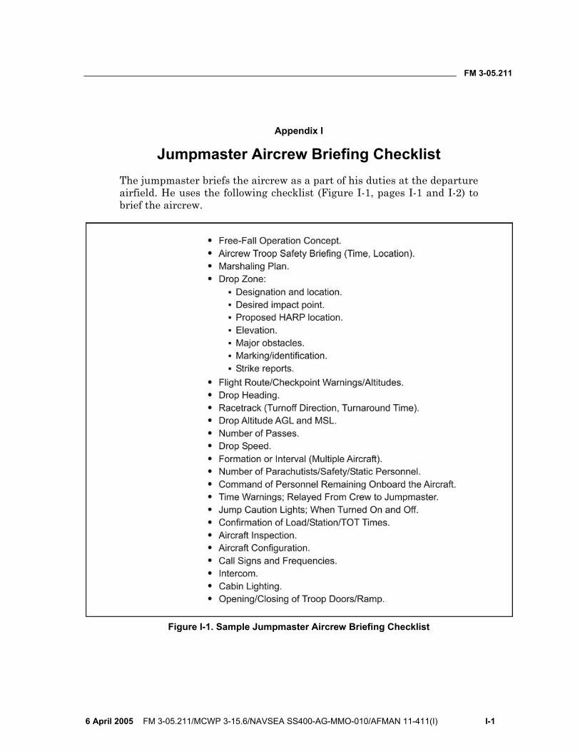
FM 3-05.211
6 April 2005 FM 3-05.211/MCWP 3-15.6/NAVSEA SS400-AG-MMO-010/AFMAN 11-411(I) I-1
Appendix I
Jumpmaster Aircrew Briefing Checklist The jumpmaster briefs the aircrew as a part of his duties at the departure airfield. He uses the following checklist (Figure I-1, pages I-1 and I-2) to brief the aircrew.
Figure I-1. Sample Jumpmaster Aircrew Briefing Checklist
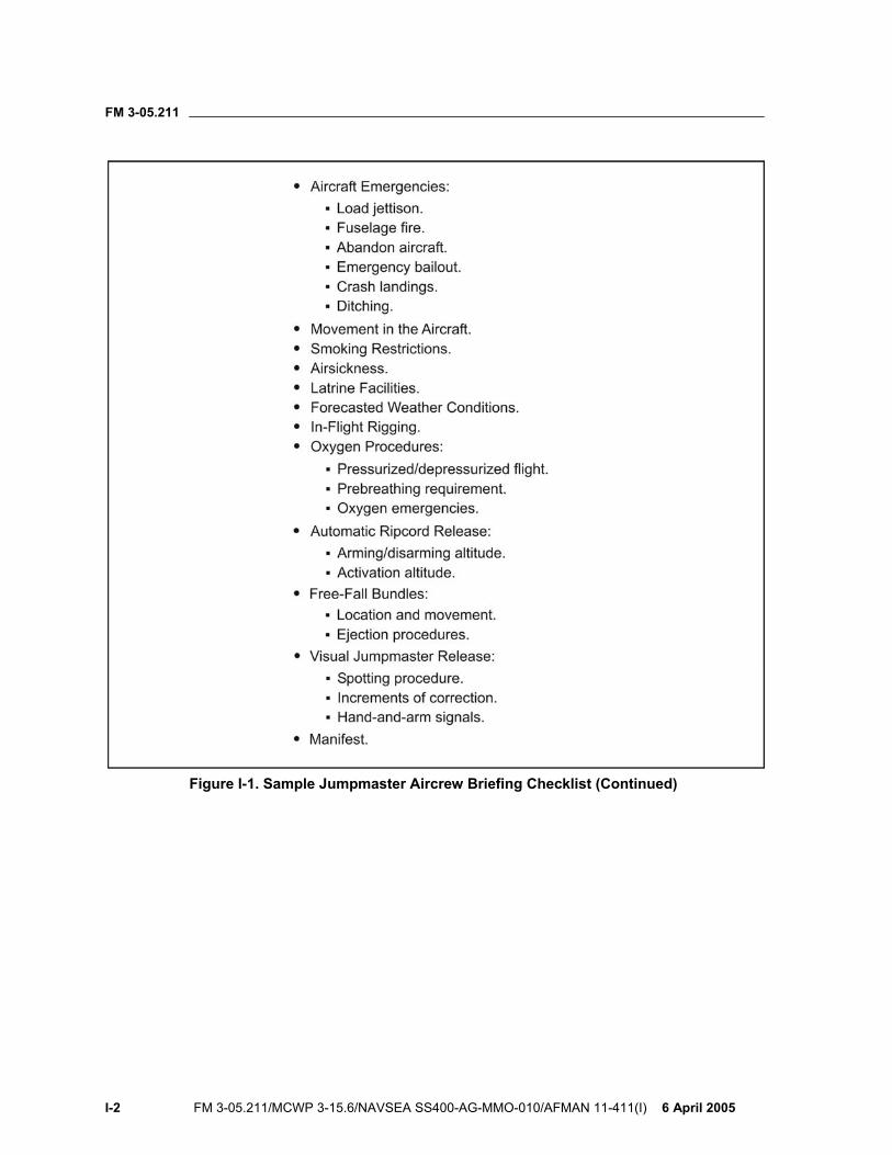
FM 3-05.211
I-2 FM 3-05.211/MCWP 3-15.6/NAVSEA SS400-AG-MMO-010/AFMAN 11-411(I) 6 April 2005
Figure I-1. Sample Jumpmaster Aircrew Briefing Checklist (Continued)
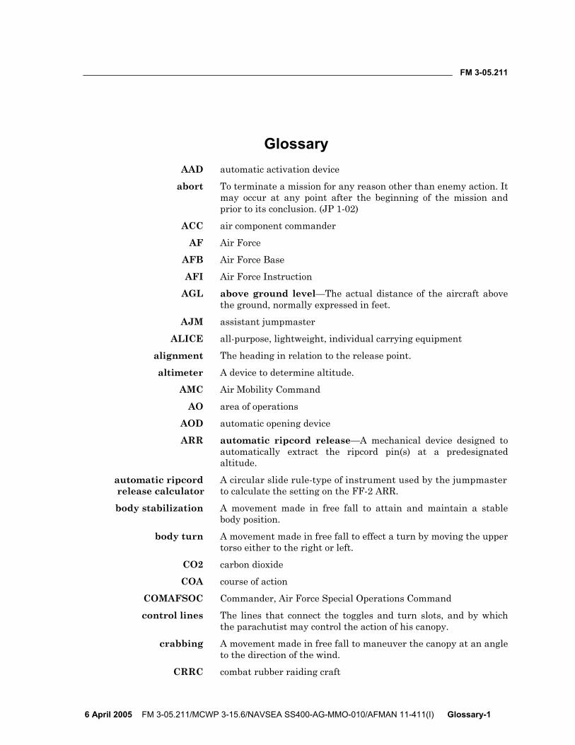
FM 3-05.211
6 April 2005 FM 3-05.211/MCWP 3-15.6/NAVSEA SS400-AG-MMO-010/AFMAN 11-411(I) Glossary-1
Glossary AAD automatic activation device
abort To terminate a mission for any reason other than enemy action. It may occur at any point after the beginning of the mission and prior to its conclusion. (JP 1-02)
ACC air component commander
AF Air Force
AFB Air Force Base
AFI Air Force Instruction
AGL above ground level—The actual distance of the aircraft above the ground, normally expressed in feet.
AJM assistant jumpmaster
ALICE all-purpose, lightweight, individual carrying equipment
alignment The heading in relation to the release point.
altimeter A device to determine altitude.
AMC Air Mobility Command
AO area of operations
AOD automatic opening device
ARR automatic ripcord release—A mechanical device designed to automatically extract the ripcord pin(s) at a predesignated altitude.
automatic ripcord A circular slide rule-type of instrument used by the jumpmaster release calculator to calculate the setting on the FF-2 ARR.
body stabilization A movement made in free fall to attain and maintain a stable body position.
body turn A movement made in free fall to effect a turn by moving the upper torso either to the right or left.
CO2 carbon dioxide
COA course of action
COMAFSOC Commander, Air Force Special Operations Command
control lines The lines that connect the toggles and turn slots, and by which the parachutist may control the action of his canopy.
crabbing A movement made in free fall to maneuver the canopy at an angle to the direction of the wind.
CRRC combat rubber raiding craft
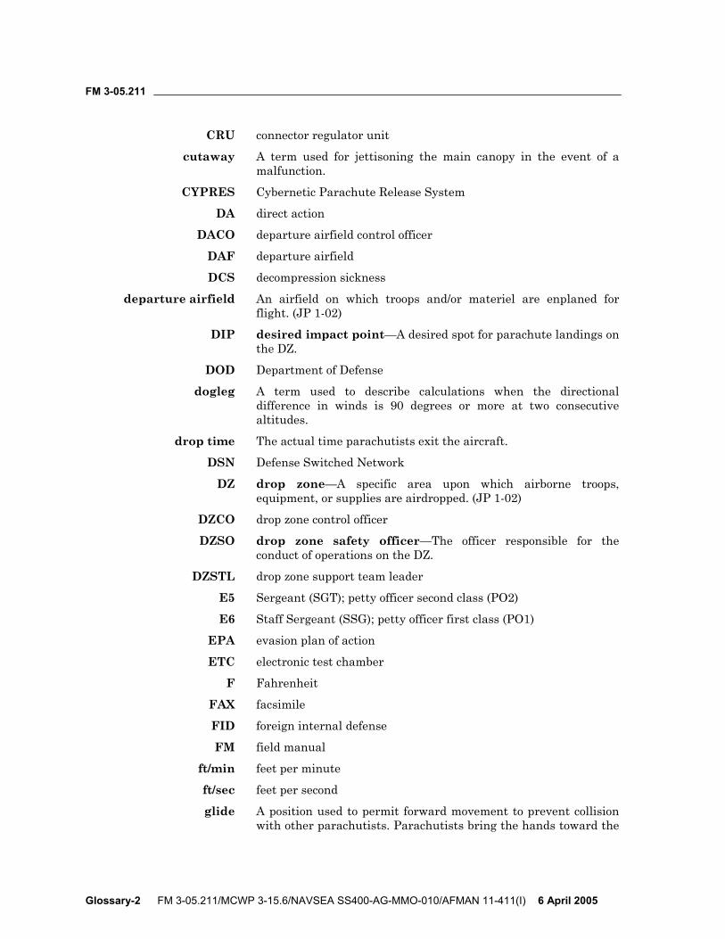
FM 3-05.211
Glossary-2 FM 3-05.211/MCWP 3-15.6/NAVSEA SS400-AG-MMO-010/AFMAN 11-411(I) 6 April 2005
CRU connector regulator unit
cutaway A term used for jettisoning the main canopy in the event of a malfunction.
CYPRES Cybernetic Parachute Release System
DA direct action
DACO departure airfield control officer
DAF departure airfield
DCS decompression sickness
departure airfield An airfield on which troops and/or materiel are enplaned for flight. (JP 1-02)
DIP desired impact point—A desired spot for parachute landings on the DZ.
DOD Department of Defense
dogleg A term used to describe calculations when the directional difference in winds is 90 degrees or more at two consecutive altitudes.
drop time The actual time parachutists exit the aircraft.
DSN Defense Switched Network
DZ drop zone—A specific area upon which airborne troops, equipment, or supplies are airdropped. (JP 1-02)
DZCO drop zone control officer
DZSO drop zone safety officer—The officer responsible for the conduct of operations on the DZ.
DZSTL drop zone support team leader
E5 Sergeant (SGT); petty officer second class (PO2)
E6 Staff Sergeant (SSG); petty officer first class (PO1)
EPA evasion plan of action
ETC electronic test chamber
F Fahrenheit
FAX facsimile
FID foreign internal defense
FM field manual
ft/min feet per minute
ft/sec feet per second
glide A position used to permit forward movement to prevent collision with other parachutists. Parachutists bring the hands toward the
FM 3-05.211
6 April 2005 FM 3-05.211/MCWP 3-15.6/NAVSEA SS400-AG-MMO-010/AFMAN 11-411(I) Glossary-3
shoulders. They do not break the arch in their back. They extend their legs slightly.
GPS global positioning system
grouping A technique used to enable parachutists to fall together in the air, remain together under canopy, and land as a compact tactical unit.
guide ring A ring attached to the rear risers through which the control lines pass.
HAHO high-altitude high-opening
HALO high-altitude low-opening
HARP high-altitude release point
heading The direction of flight.
Hg mercury
holding A term used when the canopy is pointed directly into the wind (as opposed to crabbing or running).
HPT hook-pile tape
HQ headquarters
HSPR harness, single-point release
hypoxia A lack of oxygen.
IAW in accordance with
ID identification
impact point A point on the ground where the parachutist should land.
in inches
JMPI jumpmaster personnel inspection—An inspection by the military free-fall jumpmaster similar to that of the static-line jumpmaster to ensure all safety requirements have been met.
jump commands The commands given by the jumpmaster to the parachutists on his sortie to control the parachutists’ actions between the 2-minute warning and exit.
jumpmaster The assigned airborne-qualified individual who controls parachutists from the time they enter the aircraft until they exit.
km kilometer(s)
lb pound(s)
LBE load-bearing equipment
LED light emitting diode
loadmaster An Air Force technician qualified to plan loads, to operate auxiliary materials handling equipment, and to supervise loading and unloading of aircraft. (JP 1-02)
FM 3-05.211
Glossary-4 FM 3-05.211/MCWP 3-15.6/NAVSEA SS400-AG-MMO-010/AFMAN 11-411(I) 6 April 2005
lowering line A cord designed to allow a parachutist to lower a rucksack or a piece of equipment to the ground prior to his own impact.
LOX liquid oxygen
LPU life preserver unit
malfunction A discrepancy in the deployment or inflation of the parachute that can create any faulty, irregular, or abnormal condition increasing the parachutist’s rate of descent, or a condition in which the canopy is uncontrollable.
MARCORSYSCOM Marine Corps Systems Command
mb millibar(s)—A unit of measurement of barometric pressure used when setting the FF-2 ARR.
MDMP military decision-making process
METT-TC mission, enemy, terrain and weather, troops and support available, time available, civil considerations
MFF military free fall
mm millimeter
MO malfunction officer
mph miles per hour
MSL mean sea level
NAVAIR Naval Air Systems Command
NCO noncommissioned officer
NLT not later than
nm nautical mile
nonoxygen jump A parachute jump, normally below 10,000 feet, that does not require the use of oxygen equipment.
nonoxygen procedures The signals given by the jumpmaster to control the action of the parachutists between takeoff and the 2-minute time warning when oxygen is not used.
NSN National Stock Number
opening point The point on the ground over which the parachutist deploys his canopy.
oxygen check A visual check made by the jumpmaster to see that each parachutist is receiving oxygen.
oxygen jump A free-fall parachute jump requiring the use of oxygen, normally at any altitude above 10,000 feet.
oxygen mask A face mask that may be connected to an oxygen supply, allowing parachutists to operate above nonoxygen altitudes.
oxygen procedures The procedures used by parachutists and the jumpmaster when they jump using oxygen equipment.
FM 3-05.211
6 April 2005 FM 3-05.211/MCWP 3-15.6/NAVSEA SS400-AG-MMO-010/AFMAN 11-411(I) Glossary-5
partial malfunction A situation in which the canopy does not fully deploy.
PDB parachutist drop bag
physiological training The training conducted by the Air Force to enable parachutists to identify oxygen equipment and systems and explain the effects of high-altitude physiology, cabin pressurization, and hazardous noise and stress.
pilot briefing A briefing the jumpmaster gives the pilot to clarify any points related to the airborne operation, such as drop signal, time, or alternate DZ.
PJM primary jumpmaster
PLF parachute landing fall
power cable A cable through which power is transmitted from the FF-2 ARR to the pins, securing the parachute opening.
prebreathing time The time spent prior to a high-altitude drop when the parachutists and jumpmaster breathe 100 percent oxygen.
PRICE pressure, regulator, indicator, connections, and emergency equipment
PRP preliminary release point—The point above the ground at which the initial vector stops and the free-fall drift factor begins.
psi pounds per square inch
RAPS Ram-Air Parachute System
RCLR recoilless rifle
reset indicator A window on the FF-2 ARR through which the release time-delay mechanism is checked.
RP release point—The point over which parachutists exit the aircraft.
RSL reserve static line
running A technique used for pointing the canopy in the direction of the wind.
safe-to-arm altitude An altitude 5,000 feet AGL or 2,500 feet above the ARR activation altitude, whichever is higher.
SARPELS Single-Action Release Personal Equipment Lowering System
SAW squad automatic weapon
SEAD suppression of enemy air defenses
SF safety factor
SFOD Special Forces operational detachment
SOF special operations forces
SOP standing operating procedure
FM 3-05.211
Glossary-6 FM 3-05.211/MCWP 3-15.6/NAVSEA SS400-AG-MMO-010/AFMAN 11-411(I) 6 April 2005
spotting A technique used by the jumpmaster to visually align the aircraft and release the parachutists at the proper release point.
SR special reconnaissance
STANAG Standardization Agreement
STT special tactics team—A team consisting of combat control, combat weather, and pararescue personnel.
TAS true airspeed
terminal velocity The velocity at which a falling object attains its maximum, constant speed, normally about 125 miles per hour for a free-fall parachutist.
time warnings The warnings given by the jumpmaster, in minutes, to alert the parachutist to the time remaining before exiting the aircraft.
TM technical manual
toggles The nylon loops attached to lines that control the forward speed of the canopy and left and right maneuvering, mounted on the front side of the front risers.
TOT time over target
total malfunction A type of malfunction in which the parachute remains in the pack tray.
TTP tactics, techniques, and procedures
UDT underwater demolition team
U.S. United States
USAF United States Air Force
USAJFKSWCS United States Army John F. Kennedy Special Warfare Center and School
USASOC United States Army Special Operations Command
USMC United States Marine Corps
USN United States Navy
USSOCOM United States Special Operations Command
UW unconventional warfare
V volt
walk-around bottle A large, low-pressure oxygen cylinder that may be used by either the jumpmaster or safety personnel not connected to the oxygen console or the aircraft oxygen system.
WATC wrist altimeter test chamber
WIC waterborne infiltration course
wind drift formula A formula used to locate the proper release point.

FM 3-05.211
6 April 2005 FM 3-05.211/MCWP 3-15.6/NAVSEA SS400-AG-MMO-010/AFMAN 11-411(I) Glossary-7
wind line An imaginary line extending upwind from the target area to the opening point.
ZAR Zone Availability Report

This page intentionally left blank.

FM 3-05.211
6 April 2005 FM 3-05.211/MCWP 3-15.6/NAVSEA SS400-AG-MMO-010/AFMAN 11-411(I) Bibliography-1
Bibliography Air Force Publications
AFI 11-401. Aviation Management. 12 June 2003.
AFI 11-403. Aerospace Physiological Training Program. 20 February 2001.
AFI 11-409. High Altitude Airdrop Mission Support Program. 1 December 1999.
AFI 11-410. Personnel Parachute Operations. 5 January 2004.
AFI 13-217. Drop Zone and Landing Zone Operations. 1 May 2003.
TO 14S-1-102. Maintenance Instructions With Parts Breakdown: USAF Flotation Equipment. 1 April 1986 (Change 26, 11 March 2003).
TO 15X-2-6-1. Operation and Maintenance Instructions With Illustrated Parts Breakdown, Portable Pre-Breather Oxygen System, Portable Oxygen System, Oxygen Charging System, 106 Cubic Inch Portable Oxygen System. (TM 10-1660-276-12&P.) 1 August 1997.
Army Publications
DA Form 285-AB-R. U.S. Army Abbreviated Ground Accident Report (AGAR).
FM 3-05.210. Special Forces Air Operations. 31 August 2004.
FM 3-21.38. Pathfinder Operations. 1 October 2002.
USASOC Regulation 350-2. Training Airborne Operations. 27 September 2001.
Joint and Multi-Service Publications
AR 59-4. Joint Airdrop Inspection Records, Malfunction Investigations, and Activity Reporting. (AFJ 13-210(I); OPNAVINST 4630.24C; MCO 13480.1B.) 1 May 1998.
DOD Directive 5100.1. Functions of the Department of Defense and Its Major Components. 1 August 2002.
FM 3-21.220. Static Line Parachuting Techniques and Tactics. (MCWP 3-15.7; AFMAN 11-420; NAVSEA SS400-AF-MMO-010.) 23 September 2003.
Military Series Altimeter Manual. (Issue # 40/07214/99, Issue C.) June 2001.
TM 10-1670-287-23&P. Unit and Direct Support Maintenance Manual Including Repair Parts and Special Tools List for MC-4 Ram-Air Free-Fall Personnel Parachute System (NSN 1670-01-306-2100). (TO 14D1-2-468-2; TM 09011A-23&P; NAVAIR 13-1-38.) 30 July 2003.

FM 3-05.211
Bibliography-2 FM 3-05.211/MCWP 3-15.6/NAVSEA SS400-AG-MMO-010/AFMAN 11-411(I) 6 April 2005
TM 10-1670-300-20&P. Unit and Direct Support Maintenance Manual Including Repair Parts and Special Tools List for Ancillary Equipment for: Military Free-Fall System, Helmet, Free-Fall, Parachutists, Type I (NSN 8415-01-018-4910) (8415-01-018-4911) (8415-01-018-4912) Helmet, Free-Fall, Parachutists, Type II (8415-01-018-4913) (8415-01-018-4914) (8415-01-018-4915) Goggles (8465-01-004-2893) Altimeter, Parachutists (6660-01-213-9035) Sling Assembly, Equipment Attaching (1670-01-008-7755) Line, Equipment Lowering (XXX-XX-XXX-XXXX) Release Assembly, Ripcord, Automatic, Type FF2 (1670-01-213-8145). (TO 14D1-2-469-2; NAVAIR 13-1-42.) 31 July 1995.
TM 10-1670-305-23&P. Unit and Direct Support Maintenance Manual (Including Repair Parts and Special Tools Lists) for Automatic Ripcord Release, AR2, Model 451 (NSN 1670-01-369-7914) Test Chamber Assembly, AR2, Model 452 (1670-01-370-0752) Electronic Test Chamber Assembly, AR2, Model 453 (1670-01-468-9471). (TO 14D2-11-1; NAVSEA SS400-AY-MMO-010; Marine Corps TM 1670-23&P.) 21 June 2000.
TM 55-1660-247-12. Operation, Fitting, Inspection and Maintenance Instructions With Illustrated Parts Breakdown for MBU-12/P Pressure-Demand Oxygen Mask, Part No. 834-75-01 (NSN 1660-01-081-9157LS), 834-75-02 (1660-01-073-7595LS), 834-75-03 (1660-01-073-7596LS) and 834-75-04 (1660-01-081-2368LS). (TO 15X5-3-6-1.) 1 April 1981 (Change 17, 1 September 1991).
USSOCOM Directive 10-1. Organization and Functions, Terms of Reference for Component Commanders. 19 November 2001.
Marine Corps Publications
M.C. Order 3500.20A. Marine Corps Parachuting and Diving Policy and Program Administration. 21 December 2000.
USMC TM 09770A-12&P/1A. Operational Instructions and Organizational Maintenance With Illustrated Parts Breakdown for the Ram-Air Parachute Assembly MC-5. 31 January 1997.
USMC TM 10121A-12&P. Single Action Release Personal Equipment Lowering System (SARPELS). September 1997.
Navy Publications
COMNAVSPECWARCOMINST 3000.3. Naval Special Warfare (NSW) Air Operations Manual. June 1991 (Change 2, February 1992).
NAVAIR 13-1-21. Organizational Maintenance With Illustrated Parts Breakdown, MT-1XS/SL Ram-Air Parachute Assembly. August 1994.
OPNAVINST 3501.225A. Navy Premeditated Personnel Parachuting (P3) Program. 13 January 1998.

FM 3-05.211
6 April 2005 FM 3-05.211/MCWP 3-15.6/NAVSEA SS400-AG-MMO-010/AFMAN 11-411(I) Bibliography-3
Standardization Agreement (STANAG)
STANAG 3570. Drop Zones and Extraction Zones—Criteria and Markings. 26 March 1986.

This page intentionally left blank.
FM 3-05.211
6 April 2005 FM 3-05.211/MCWP 3-15.6/NAVSEA SS400-AG-MMO-010/AFMAN 11-411(I) Index-1
IndexA
accident report sample, E-2, E-3
aircraft jump commands, 6-7 through 6-13
abort, 6-12, 6-13 disarm automatic ripcord
release (ARR), 6-3, 6-13
go, 6-2, 6-12 move to the rear, 6-2, 6-11 stand by, 6-2, 6-11 stand up, 6-2, 6-10
aircraft procedure signals, 6-1 through 6-7
arm ARR, 6-2, 6-7, 6-10 check oxygen, 6-3, 6-6,
6-7 don helmets, 6-1, 6-3 emergency bailout, 6-4,
6-5 mask, 6-1, 6-6 time warnings, 6-1, 6-6,
6-8 unfasten seat belts, 6-1,
6-4 wind speed, 6-2, 6-7, 6-9
AIROX VIII assembly, 4-11 through 4-15
altimeter MA2-30/A, 2-3, 2-14 PA-200, 2-3, 2-14 setting computation, 2-15
AR2 barometric calculator, 3-9 through 3-20
ARR activation setting and
operation, 3-1 AR2 ARR, M451, 2-13, 3-6
through 3-9 calculation of millibar
setting, 3-3, 3-5
FF-2 arming, 3-6 FF-2 ARR assembly, 2-12,
3-2 FF-2 disarming, 3-6 Military Cybernetic
Parachute Release System (CYPRES), 3-22 through 3-31
Sentinel MK 2100, 3-20 through 3-22
aviator’s kit bag attaching the modified
H-harness, 5-6 attaching to parachutist,
5-6 donning, 5-13 front mounting, 5-14, 5-15 preparing, 5-5 rear mounting, 5-11
through 5-14
B body positions for altimeter
check body turn, 7-2 diving exit, 7-2 gliding, 7-3 main ripcord pull, 7-4 poised exit, 7-1 stable free fall, 7-2
C calculations
canopy drift, F-4 doglegs, F-4 drift and direction, F-3 forward throw, F-4 high-altitude release point
(HARP), F-1, F-2, F-5 through F-8
canopy control
crabbing, 8-12 through 8-14
full brakes, 8-15 full flight, 8-14 half brakes, 8-14, 8-15 holding maneuver, 8-11 running maneuver, 8-12 stall, 8-16 through 8-18
canopy entanglement procedures, 9-8
checklists aircraft inspection, H-1 canopy control, 8-11 jumpmaster briefing, I-1,
I-2 jumpmaster
responsibilities, 13-1, 13-2
portable bailout oxygen system preflight inspection and operational, 4-20, 4-21
prebreather preflight inspection and operational function, 4-21, 4-22
combat packs, medium and large
attaching, 5-11 through 5-15
packing, 5-7 releasing, 5-15, 5-16 rigging, 5-7 through 5-9
containers aviator’s kit bag, 5-5, 5-6 combat packs, 5-7 MC-4 kit bag, 5-5, 5-6
controllability check, 9-3 cutaway handle, 2-4, 2-7
FM 3-05.211
Index-2 FM 3-05.211/MCWP 3-15.6/NAVSEA SS400-AG-MMO-010/AFMAN 11-411(I) 6 April 2005
CYPRES CYPRES Military Absolute
Adjust Circular Calculator, 3-28
CYPRES Military Absolute Adjust Model Calculator, 3-29 through 3-31
D doglegs, calculating, F-4 drift and direction, calculating,
F-3 drop zone control officer
(DZCO), 11-4, 11-5 United States Air Force
(USAF), 11-5 drop zones (DZs)
authentication system, 11-7
malfunction officer, 11-5, 11-6
markings, 11-6, 11-7, 12-4 personnel qualifications
and responsibilities, 11-3 through 11-6
selection criteria, 11-1, 11-2
special tactics team (STT), 11-5
support team leader, 11-3, 11-4
water DZs, 12-4 drop zone safety officer
(DZSO), 11-3 through 11-5
E emergency procedures
free fall, 9-5 in-flight, 9-4 landing, 9-3 ram-air parachute system
(RAPS), 9-1 through 9-8 entanglement, RAPS, 9-8 evasion plan of action (EPA),
1-2
F forward throw, calculating, F-4 free-fall delays, 10-3
H harness, single-point release
(HSPR) attaching HSPR and all-
purpose, lightweight, individual carrying equipment (ALICE) pack to parachutist, 5-30, 5-31
rigging ALICE pack with, 5-27 through 5-30
HARP calculation, F-1 through F-8
helmet assembly, 2-2, 2-13, 2-14
H-harness (modified), 5-5, 5-7, 5-8
high-altitude high-opening (HAHO) offset parachuting
currency and requalification, B-1, B-2
free-fall delays, 10-3 jump phases, 10-3, 10-4 special equipment needs,
10-2, 10-3 techniques, 10-1, 10-2
I in-flight emergency
procedures, 9-4 inspections
aircraft, H-1 jumpmaster personnel,
G-1 through G-17
J jumpmaster
briefing checklist, I-1, I-2 cardinal rules, 13-2, 13-3 qualifications, 13-2, 13-3 responsibilities, 13-1, 13-2
jumpmaster personnel inspection, G-1 through G-17
L landing approaches
base leg, 8-18 downwind leg, 8-18 final approach, 8-18
landing procedures, emergency, 9-3
life preservers B-7, 5-50 through 5-52 LPU-10/P, 5-52 UDT, 5-52, 5-53
limited-visibility operations adverse weather, 10-5,
10-6 night operations, 10-6
load limitations parachute, 5-2 parachutist, 5-2, 5-3
lowering line assembly, 5-3, 5-4
M main parachute, 2-1, 2-9 malfunctions
bag lock, 9-7 broken control lines, 9-7 broken lines, 9-7 closed end cells, 9-7 floating ripcord, 9-6 hard pull, 9-6 horseshoe, 9-7 hung slider, 9-7 line twists, 9-7 main parachute, 9-7 pack closure, 9-7 partial (RAPS), 9-6 pilot chute
hesitation, 9-7 inadvertent deployment,
9-2 over the nose, 9-6
FM 3-05.211
6 April 2005 FM 3-05.211/MCWP 3-15.6/NAVSEA SS400-AG-MMO-010/AFMAN 11-411(I) Index-3
rips, 9-7 tears, 9-7 tension knots, 9-7 total (RAPS), 9-6
masks, oxygen cleaning, 4-10 fitting, 4-10, 4-11 types, 4-7 through 4-9
MC-4 RAPS altimeter, 2-14, 2-15 AR2 ARR assembly, 2-13 canopy release assembly,
2-6 FF-2 ARR assembly, 2-12 harness assembly, 2-4 helmet assembly, 2-13,
2-14 jumpmaster personnel
inspection, G-1 through G-17
main parachute assembly, 2-1, 2-9, 2-11
malfunction procedures, 9-6, 9-7
parachute recovery, 2-18 personnel oxygen system
assembly, 4-8 through 4-13
reserve parachute assembly, 2-9, 2-11
military decision-making process (MDMP), 1-6
military free-fall (MFF) parachute operations
characteristics, 1-1, 1-2 considerations, 1-2
through 1-5 critical task lists, A-1
through A-12 deliberate water, 12-1
through 12-6 medical and physiological
training requirements, B-1
oxygen, 4-1 through 4-24 mission, enemy, terrain and
weather, troops and support
available, time available, civil considerations (METT-TC) analysis, 1-4, 1-5
O oxygen
AIROX VIII assembly, 4-11 through 4-15
equipment-related emergencies, 4-3, 4-4
forms of, 4-4, 4-5 handling and safety, 4-24 MA-1 portable oxygen
assembly, 4-17 masks, 4-7 through 4-11 physiological effects of,
4-1 through 4-3 portable bailout oxygen
system (106-cubic-inch), 4-11 through 4-15
prebreather attachment, 4-17, 4-18
pressure, regulator, indicator, connections, and emergency equipment (PRICE) check, 4-19
requirements, 4-5, 4-6 safety personnel, 4-19
through 4-23 six-man prebreather
portable oxygen system, 4-15, 4-16
oxygen fitting block, 4-13, 4-14
P parachuting techniques,
HAHO, 10-1, 10-2 postopening procedures, 9-4 prebreather
attachment, 4-17 through 4-19
portable, six-man, 4-15, 4-16
preflight operational checklists, 4-21, 4-22
R ram-air parachute
canopy control, 8-9 through 8-19
characteristics, 8-1 through 8-3
deployment sequence, 8-3 through 8-7
flight characteristics, 8-8, 8-9
theory of flight, 8-7, 8-8 RAPS
components, 2-4 through 2-15, 8-2, 8-3
cutaway procedures, 8-6, 9-6
donning, 2-15 through 2-18
recovery of, 2-15, 2-18 reserve ripcord handle, 2-8 reserve risers, 2-8, 2-10 rigging
combat packs, medium and large, 5-7 through 5-10
FN FAL rifle, 5-41, 5-42 G3 rifle, 5-41, 5-42 M14 rifle, 5-41, 5-42 M16-series and M4
carbine-series rifles, 5-37, 5-38
M60 machine gun, 5-44, 5-45
M203 grenade launcher, 5-40, 5-41
M224 60-mm mortar, 5-48, 5-49
MP5 submachine gun, 5-42 through 5-44
MP5A3 submachine gun, 5-43, 5-44
MP5K, 5-43, 5-44 other weapons, 5-45
through 5-48, 5-50
FM 3-05.211
Index-4 FM 3-05.211/MCWP 3-15.6/NAVSEA SS400-AG-MMO-010/AFMAN 11-411(I) 6 April 2005
S safety personnel, oxygen
duties of, 4-19 through 4-24 Sentinel MK 2100, 3-20
through 3-22 Single-Action Release
Personal Equipment Lowering System (SARPELS)
installing the 8-foot MFF lowering line, 5-23, 5-24
loading the SARPELS cargo carrier, 5-16 through 5-20
mounting the SARPELS cargo container, 5-24, 5-25
rigging the SARPELS cargo carrier, 5-20 through 5-23
special tactics team (STT), 1-1 suppression of enemy air
defenses (SEAD), 1-2
T three-ring canopy release
assembly, 2-6 training
HAHO requalification and refresher, B-2
MFF requalification and refresher, B-1, B-2
proficiency, C-1 sustained airborne, D-1
through D-5 tabletop body stabilization,
7-1 through 7-3
W water operations, deliberate
DZ pickup procedures, 12-5, 12-6
DZ requirements and markings, 12-4
equipment recovery boats, 12-1
equipment requirements, 12-2 through 12-4
night water parachute operations, 12-6
parachutist procedures, 12-4, 12-5
parachutist recovery boats, 12-1
parachutist requirements, 12-2
safety swimmers, 12-2 support for water drops,
12-1, 12-2 water jumps with combat
equipment, 12-6
FM 3-05.211 (FM 31-19) MCWP 3-15.6
NAVSEA SS400-AG-MMO-010 AFMAN 11-411(I)
6 April 2005
By Order of the Secretary of the Army: Official: DISTRIBUTION: Active Army, Army National Guard, and U. S. Army Reserve: To be distributed in accordance with initial distribution number 111110, requirements for FM 3-05.211.
PETER J. SCHOOMAKER General, United States Army
Chief of Staff
SANDRA R. RILEY Administrative Assistant to the
Secretary of the Army 0507506

This page intentionally left blank.

PIN: 082352-000


![(eBook Military) - Fm 3-05 20 [31-20] Special Forces Operations](https://img.dokumen.tips/doc/110x75/577cd0be1a28ab9e78930498/ebook-military-fm-3-05-20-31-20-special-forces-operations.jpg)