Embed Size (px)
Citation preview
®
Flowserve Pump Division
I.O.M. Installation, Operation and Maintenance
IDP® PumpsType CPXP
SELF PRIMING, FRAME MOUNTEDCHEMICAL PROCESS PUMP
Instruction Manual C961KH001 - 03/02
INSTRUCTION MANUAL CPXP ENGLISH C961KH001 - 03/02
®
2
INTRODUCTION
Flowserve
Flowserve's products and brands are the leading names in their fields: the CPX range ofprocess pumps specifically focus on demanding chemical process applications. The pumpsare manufactured at modern facilities, utilising state of art equipment and sophisticated qualitycontrol techniques. Flowserve is proud of earning preferred supplier status to many of world'sleading processing companies. Engineered, manufactured, sold and serviced to ISO 9001quality certification, Flowserve pumps are truly world class products.
With more than 120 years of experience in servicing the needs of world-wide processindustries, Flowserve has become the unchallenged leader in hydraulic design engineering,materials expertise and application know-how. Committed to continuous quality improvement,Flowserve controls the complete product life cycle - from application engineering, design,melting and casting, to cellular manufacturing, to assembly and testing, to the supply ofaftermarket products, repair and diagnostic services.
Flowserve is on hand to provide technical support and special services specific to the needs ofits customers.
CopyrightAll rights reserved. No part of this manual may be reproduced, stored in a retrieval system ortransmitted in any form or by any means without prior permission of Flowserve Pump Division.
CE Mark SystemIt is a legal requirement that machinery and equipment put into service within the EuropeanUnion shall conform with the applicable European Union Directives covering Machinery, LowVoltage Equipment and EMC.
Where applicable the European Union Directives cover important Safety aspects relating tomachinery and equipment and the satisfactory provision of technical documents and safetyinstructions. This document incorporates information relevant to these Directives. TheManual should be read prior to installing, operating, using and maintaining the equipment.The equipment must not be put into service until all the conditions relating to safety noted inthe Manual have been met.
DisclaimerFlowserve manufactures products to exacting International Quality Management SystemStandards (ISO 9001) as certified and audited by Lloyd's Register Quality Assurance Limited.Genuine parts and accessories have been designed, tested and incorporated into theproducts to ensure their continued product quality and performance in use. As Flowservecannot test parts and accessories sourced from other vendors the incorrect incorporation ofsuch parts and accessories may adversely affect the performance and safety features of theproducts. The failure to properly select, install or use authorised Flowserve parts andaccessories is considered to be misuse. Damage or failure caused by misuse is not coveredby Flowserve's warranty. In addition, any modification of Flowserve products or removal oforiginal components may impair the safety of these products in their use.
INSTRUCTION MANUAL CPXP ENGLISH C961KH001 - 03/02
®
3
1 NAMEPLATE & WARNING LABELS
1.1 Nameplate
For details of nameplate, see the Declaration of conformity
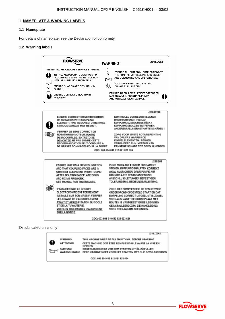
1.2 Warning labels
Oil lubricated units only

INSTRUCTION MANUAL CPXP ENGLISH C961KH001 - 03/02
®
4
2 SAFETY
2.1 Duty conditions
2.1.1 This pump has been selected to meet the dutyand service conditions advised on your order. Theacknowledgement of these conditions has been sentseparately to the Purchaser. A copy should be keptwith this manual.
2.1.2 If there is any doubt as to the suitability of thepump for the application intended, contact Flowservefor advice, quoting the pump serial number.
2.2 Safety actionAlways co-ordinate repair activity with operationspersonnel, and follow all plant safety requirements andapplicable safety and health laws/regulations.
THIS IS A SUMMARY OF CONDITIONS ANDACTIONS TO PREVENT INJURY TO PERSONNELAND DAMAGE TO EQUIPMENT.
� This sign indicates safety instructionswhere non-compliance would affect personal safety.
� This symbol indicates electrical safetyinstructions where non-compliance would affectpersonal safety.
� This symbol indicates safety instructions wherenon-compliance would affect the safe operation orprotection of the pump or pump unit.
2.2.1 � PREVENT EXCESSIVE EXTERNALPIPE LOADDo not use pump as a support for piping. Do notmount expansion joints so that their force, due tointernal pressure, acts on the pump flange.
2.2.2 � ONLY CHECK DIRECTION OF MOTORROTATION WITH COUPLING ELEMENT/PINSREMOVEDStarting in reverse direction of rotation will damage thepump.
2.2.3 � START THE PUMP WITH OUTLETVALVE CLOSEDThis is recommended to avoid the risk of overloadingand damaging the pump motor at full flow. Pumpsmay be started with the valve open only oninstallations where this situation cannot occur.
2.2.4 � ENSURE CORRECT LUBRICATION(See: "Making ready for operation - Lubrication".)
2.2.5 � NEVER RUN THE PUMP DRY
2.2.6 � INLET VALVES TO BE FULLY OPENWHEN PUMP IS RUNNINGRunning the pump at zero flow or below therecommended minimum flow continuously will causethe shaft, packing or mechanical seal to run hot and failwithin a short time.
2.2.7 � DO NOT RUN THE PUMP ATABNORMALLY HIGH OR LOW FLOW RATESOperating at a flow rate higher than normal or at a flowrate with no back pressure on the pump may overloadthe motor and cause cavitation. Low flow rates maycause a reduction in pump/bearing life, overheating ofthe pump, instability and cavitation/vibration.
2.2.8 � NEVER DO MAINTENANCE WORKWHILST THE UNIT IS CONNECTED TO POWER
2.2.9 � NEVER APPLY HEAT TOREMOVE IMPELLERTrapped lubricant or vapour could cause an explosion.
2.2.10 � HANDLING COMPONENTSMany precision parts have sharp corners and the wearingof appropriate safety gloves and equipment is requiredwhen handling these components. To lift heavy piecesabove 30kg (66lbs) use a crane corresponding to themass and in accordance with current local regulations.
2.2.11 � DRAIN PUMP AND ISOLATEPIPEWORK BEFORE DISMANTLING THE PUMPThe appropriate safety precautions should be takenwhere the pumped liquids are hazardous.
2.2.12 � FLUORO-ELASTOMERS(When fitted to high temperature units).
When a pump has experienced temperatures over250°C(482ºF), partial decomposition of fluoro-elastomers (eg viton) will occur. In this condition theseare extremely dangerous and skin contact must beavoided.
2.2.13 � THERMAL SHOCKRapid changes in the temperature of the liquid withinthe pump can cause thermal shock, which can result indamage or breakage of components. Thermal shockshould be avoided, particularly so where the materialof the pump is not resistant to such loading.
2.2.14 � HOT (and cold) PARTSIf hot or freezing components or auxiliary heatingsupplies can present a danger to operators, they mustbe shielded to avoid accidental contact. If completeprotection is not possible, machine access must belimited to maintenance staff only. Note: drive motorsand bearings may be hot.
IF THE TEMPERATURE IS GREATER THAN 80°C(175°F) OR BELOW 5°C (20°F), A VISUALWARNING INDICATOR SUCH AS A WARNINGPLATE MUST BE PLACED CLEARLY ON THEEQUIPMENT.
2.2.15 � HAZARDOUS LIQUIDSWhen the pump is handling hazardous liquids caremust be taken to avoid liquid contact using theappropriate health and safety procedures. Pumplocation and personnel access/training should considerand address these site dangers.

INSTRUCTION MANUAL CPXP ENGLISH C961KH001 - 03/02
®
5
2.3 Potentially explosive atmospheresAlways check that the driver, drive coupling assemblyand pump equipment are suitably rated and/or certifiedfor the classification of the specific atmosphere inwhich they are to be installed. See section 16,Certification.
INSTRUCTION MANUAL CPXP ENGLISH C961KH001 - 03/02
®
6
3. CONTENTSPAGE
INTRODUCTION 2
1 NAMEPLATE & WARNING LABELS 3
2 SAFETYDuty conditions 4Safety action 4Potentially explosive atmospheres 5
3 CONTENTS 6
4 PUMP TECHNICAL DATAPerformance 7Noise level 7Pressure limits 7Flange loads 7Pump lubricants 8Recommended screw torques 8
5 PRODUCT DESCRIPTIONGeneral 9Pump casing 9Impeller 9Shaft 9Bearing housing 9Pump bearings and lubrication 9Seal housing 9Shaft seal 9Driver 9Accessories 9
6 STORAGE 9
7 INSTALLATIONUnpacking and inspection 9Handling 9Location 10Foundation 10Grouting 10Alignment of couplings 10Electrical connections 11Pipework connections 11Final piping check 12Auxiliary piping 12
8 MAKING READY FOR OPERATIONLubrication 12Direction of rotation 13Guarding 13Open impeller clearance 13Primary and auxiliary supplies 13Filling and self priming 13
9 STARTING AND RUNNING THE PUMPStarting 13Running pumps fitted with packed glands 14Running pumps fitted with mechanical seals 14Stop/start frequency 14
PAGE
10 STOPPING AND SHUTDOWN 14
11 PREVENTATIVE MAINTENANCE &SERVICINGMaintenance schedule 14Routine inspection (daily/weekly) 14Periodic inspection (6 monthly) 14Lubrication data 14Gland packing 15Mechanical seals 15Setting impeller front clearance 15
12 DISMANTLING AND ASSEMBLYDismantling 15Examination of parts 16Assembly 17
13 SEALING ARRANGEMENTSSingle seal types 19Cartridge seal types 20Tandem seal types 20Double seal types 20External seal types 20Packed gland seal types 20
14 SPARE PARTSOrdering of spares 21Storage of spares 21Recommended spares 21
15 GENERAL ARRANGEMENT DRAWING 21
16 CERTIFICATION 21
17 SUPPLEMENTARY INSTRUCTIONMANUALS 21
18 CHANGE NOTES 21
19 OPERATING DIFFICULTIES 22
20 SECTIONAL ARRANGEMENTDRAWINGS AND PARTS LISTS 23-24
21 PARTS INTERCHANGEABILITY 25
INSTRUCTION MANUAL CPXP ENGLISH C961KH001 - 03/02
®
7
4 PUMP TECHNICAL DATA
4.1 PerformanceFor performance parameters see the paragraph onSafety - Duty conditions. When specified by thecontract, performance data has been suppliedseparately to the purchaser and should be obtainedand retained with this manual if required.
4.2 Noise level
4.2.1 When pump noise level exceeds 85dBAattention must be given to prevailing Health and SafetyLegislation, to limit the exposure of plant operatingpersonnel to the noise. The usual approach is tocontrol exposure time to the noise or to enclose themachine to reduce emitted sound.
You may have already specified a limiting noise levelwhen the equipment was ordered, however if nonoise requirements were defined then machinesabove a certain power level will exceed 85dBA.
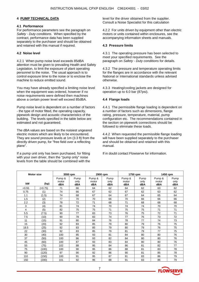
Pump noise level is dependent on a number of factors- the type of motor fitted, the operating capacity,pipework design and acoustic characteristics of thebuilding. The levels specified in the table below areestimated and not guaranteed.
The dBA values are based on the noisiest ungearedelectric motors which are likely to be encountered.They are sound pressure levels at 1m (3.3 ft) from thedirectly driven pump, for "free field over a reflectingplane".
If a pump unit only has been purchased, for fittingwith your own driver, then the "pump only" noiselevels from the table should be combined with the
level for the driver obtained from the supplier.Consult a Noise Specialist for this calculation
4.2.2 For units driven by equipment other than electricmotors or units contained within enclosures, see theaccompanying information sheets and manuals.
4.3 Pressure limits
4.3.1 The operating pressure has been selected tomeet your specified requirements. See theparagraph on Safety - Duty conditions for details.
4.3.2 The pressure and temperature operating limitsfor the flanges are in accordance with the relevantNational or International standards unless advisedotherwise.
4.3.3 Heating/cooling jackets are designed foroperation up to 6.0 bar (87psi).
4.4 Flange loads
4.4.1 The permissible flange loading is dependent ona number of factors such as dimensions, flangerating, pressure, temperature, material, pumpconfiguration etc. The recommendations contained inthe section on pipework connections should befollowed to eliminate these loads.
4.4.2 When requested the permissible flange loadingwill have been supplied separately to the purchaserand should be obtained and retained with thismanual.
If in doubt contact Flowserve for information.
3550 rpm 2900 rpm 1750 rpm 1450 rpmMotor size
kW (hp)
Pump &motordBA
PumponlydBA
Pump &motordBA
PumponlydBA
Pump &motordBA
PumponlydBA
Pump &motordBA
PumponlydBA
<0.55 (<0.75) 71 66 64 62 64 62 63 620.75 (1) 74 66 67 62 67 62 63 621.1 (1.5) 74 68 67 64 67 64 65 641.5 (2) 77 70 70 66 70 66 66 662.2 (3) 78 72 71 68 71 68 68 683 (4) 81 74 74 70 74 74 70 704 (5) 82 75 75 71 75 75 71 71
5.5 (7.5) 90 77 83 73 76 75 72 717.5 (10) 90 78 83 74 77 76 73 7211 (15) 91 80 84 76 78 77 74 7315 (20) 92 83 85 79 80 79 76 75
18.5 (25) 92 83 85 79 80 79 76 7522 (30) 92 83 85 79 81 79 77 7530 (40) 100 85 93 81 84 80 80 7637 (50) 100 86 93 82 84 80 80 7645 (60) 100 87 93 83 84 80 80 7655 (75) 102 88 95 84 86 81 82 7775 (100) 100 90 95 86 88 81 83 7890 (120) 97 90 92 86 90 81 85 78110 (150) 100 91 95 87 91 83 86 79150 (200) 101 92 96 88 91 83 86 79

INSTRUCTION MANUAL CPXP ENGLISH C961KH001 - 03/02
®
8
4.5 Pump lubricants
4.5.1 Recommended oil lubricantsOil Splash lubrication Force feed lubrication
Viscositymm²/s 40ºC 32 68 46
Temp. maximumºC (ºF) 65 (149) 80 (176) -
Cen
tifug
al p
ump
lubr
icat
ion
Designationaccording to
DIN51502 ISO VGHL/HLP 32 HL/HLP 68 HL/HLP 46
BP BP Energol HL32BP Energol HLP32
BP Energol HL68BP Energol HLP68
BP Energol HL46BP Energol HLP46
DEA Anstron HL32Anstron HLP32
Anstron HL68Anstron HLP68
Anstron HL46Anstron HLP46
ElfOLNA 32
HYDRELEF 32TURBELF 32
ELFOLNA DS32
TURBELF SA68
ELFOLNA DS68
TURBELF SA46
ELFOLNA DS46
Esso TERESSO 32NUTO H32
TERESSO 68NUTO H68
TERESSO 46NUTO H46
Mobil Mobil DTE oil lightMobil DTE13MobilDTE24
Mobil DTE oil heavy medium
Mobil DTE26
Mobil DTE oil mediumMobil DTE15MMobil DTE25
Q8 Q8 Verdi 32Q8 Haydn 32
Q8 Verdi 68Q8 Haydn 68
Q8 Verdi 46Q8 Haydn 46
Shell Shell Tellus 32Shell Tellus 37
Shell Tellus 01 C 68Shell Tellus 01 68
Shell Tellus 01 C 46Shell Tellus 01 46
Texaco Rando Oil HD 32Rando Oil HD-AZ-32
Rando Oil 68Rando Oil HD C-68
Rando Oil 46Rando Oil HD B-46
Oil
com
pani
es a
nd lu
bric
ants
Wintershall(BASF Group
Wiolan HN32Wiolan HS32
Wiolan HN68Wiolan HS68
Wiolan HN46Wiolan HS46
4.5.2 Bearing sizes and oil capacitiesMedium duty bearings Heavy duty bearings
Pump end Drive end Pump end Drive endFrame sizeBall bearing Duplex back-to-
back ACRoller bearing Duplex back-to-
back AC
Oil capacityapproximatelyLitres (gallons)
123
6207 C36309 C36311 C3
3306 C33309 C33311 C3
NUP 207 C3NUP 309 C3NUP 311 C3
730673097311
0.5 (0.14)1.2 (0.32)1.2 (0.32)
NB: The bearing sizes do not constitute a purchasing specification.
4.5.3 Recommended grease lubricantsGrease nipplesGrease
NLGI 2 * NLGI 3 **Temp. range ºC
(ºF)-20 to +100(-4 to +212)
-20 to +100(-4 to +212)
Designationaccording to DIN K2K-20 K2K 30
BP Energrease LS2 Energrease LS3DEA Glissando 20 Glissando 30Elf Elfmulti 2 Elfmulti 3
Esso Beacon 2 Beacon 3Mobil Mobilux 2 Mobilux 3
Q8 Rembrandt 2 Rembrandt 3Shell Alvania Fett G2
Alvania Fett R2Alvania R3
Texaco Multilak 20Multilak EP2
Multilak 30Multilak EP3
Wintershall(BASF Group Wiolub LFK 2 -
SKF LGMT 2 LGMT 3Silkolene G55/T G56/T
* NLGI 2 is an alternative grease and is not to be mixed with othergrades.** Factory packed bearings for the temperature range with greasenipples.
4.5.4 Grease lubricated bearing capacitiesFrame size Pump end Drive end
Ball/roller bearing Duplex back to backAC
1 45 cm3 (2.75 inch3) 75 cm3 (1.65 inch3)2 105 cm3 (6.45 inch3) 150 cm3 (9.15 inch3)3 150 cm3 (9.15 inch3) 300 cm3 (18.3 inch3)
4.6 Recommended screw torques
Screwposition
Screw size TorqueNm (lbf ft)
Casing andseal cover
M8M10M12M16M20
16 (12)25 (18)35 (26)80 (59)130 (96)
INSTRUCTION MANUAL CPXP ENGLISH C961KH001 - 03/02
®
9
5 PRODUCT DESCRIPTION
5.1 GeneralThe pump is a modular designed centrifugal pumpwhich can be built to achieve almost all chemicalliquid pumping requirements.
5.2 Pump casingThe pump casing is designed with a self primingaction which works on the reflux principle for suctionlifts up to 7m (23 ft). It has a horizontal centreline endinlet and a vertical centreline top outlet which makesit self venting.
For ease of maintenance, the pump is constructed sothat pipe connectors do not have to be disturbedwhen internal maintenance is required.
5.3 ImpellerAn open impeller is fitted.
5.4 ShaftThe large diameter stiff shaft, mounted on bearings,has a keyed drive end.
5.5 Bearing housingThe bearing housing enables adjustment of impellerface clearance (open impellers only) via the bearingcarrier jacking screws.
5.6 Pump bearings and lubricationThe pump is fitted with ball and/or roller type bearingswhich may be configured differently dependent onuse.
The bearings may be oil or grease lubricated.
5.7 Seal housingThe seal housing has spigots between the pumpcasing and bearing housing for optimum concentricity.
A fully confined gasket forms the seal between thepump casing and the seal housing.
The seal housing designs provide improvedperformance of mechanical seals.
The design enables one of a number of sealingoptions to be fitted.
5.8 Shaft sealThe mechanical seal(s) attached to the drive shaftseals the pumped liquid from the environment.(Gland packing may be fitted as an option.)
5.9 DriverThe DRIVER is normally an electric motor. Differentdrive configurations may be fitted such as an internalcombustion engine, turbines, hydraulic motors etcdriving via couplings, belts, gearboxes, drive shaftsetc.
5.10 AccessoriesAccessories may be fitted when specified by thecustomer
Fan cooling is available for high temperatureoperation. This is a fan fitted within the couplingguard to blow cooling air over the bearing housingand shaft.
6 STORAGEStore the pump in a clean, dry location away fromvibration. Leave piping connection covers in place tokeep dirt and other foreign material out of pumpcasing. Turn pump at intervals to prevent brinelling ofthe bearings and the seal faces, if fitted, from sticking.
The pump may be stored as above for up to 6months. Consult Flowserve for preservative actionswhen a longer storage period is needed.
Warranty for the pumps will normally be for 12months. Extension of this period can only beachieved with the prior agreement of Flowserve andwould necessitate inspection, prior to putting thepump into service.
7 INSTALLATION
7.1 Unpacking and inspectionThe pump should be checked against the deliveryadvice note and any damage or shortage reportedimmediately to Flowserve. Any crate, carton orwrappings should be checked for spare parts oraccessories that may be packed with the pump.
7.2 Handling
7.2.1 Boxes, crates, pallets or cartons may beunloaded using fork lift vehicles or slings dependenton their size and construction.
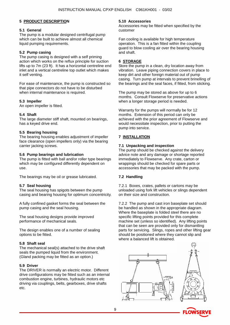
7.2.2 The pump and cast iron baseplate set shouldbe handled as shown in the appropriate diagram.Where the baseplate is folded steel there are nospecific lifting points provided for this completemachine set (unless so identified). Any lifting pointsthat can be seen are provided only for dismantlingparts for servicing. Slings, ropes and other lifting gearshould be positioned where they cannot slip andwhere a balanced lift is obtained.
INSTRUCTION MANUAL CPXP ENGLISH C961KH001 - 03/02
®
10
7.3 LocationThe pump should be located to allow room for access,ventilation, maintenance and inspection with ampleheadroom for lifting and should be as close aspracticable to the supply of liquid to be pumped.
7.4 Foundation
7.4.1 There are many methods of installing pump unitsto their foundations. The correct method depends onthe size of the pump unit, its location and noisevibration limitations. Non-compliance with theprovision of correct foundation and installation maylead to failure of the pump and as such, would beoutside the terms of the warranty.
7.4.2 The baseplate should be mounted onto a firmfoundation, either an appropriate thickness of qualityconcrete or sturdy steel framework. It should NOT bedistorted or pulled down onto the surface of thefoundation, but should be supported to maintain theoriginal alignment.
7.4.3 Install the baseplate onto packing pieces evenlyspaced and adjacent to foundation bolts. Level withshims between baseplate and packing pieces. Thepump and driver have been aligned before dispatch.Check alignment of pump and motor half coupling. Ifthis is incorrect, it indicates that the baseplate hasbecome twisted and should be corrected by re-shimming.
7.5 Grouting
7.5.1 Where applicable, grout in the foundation bolts.
7.5.2 After adding pipework connections andrechecking the coupling alignment, the baseplateshould then be grouted in accordance with goodengineering practice. Fabricated steel, cast iron andepoxy baseplates can be filled with grout. Folded steelbaseplates should be grouted to locate their packingpieces. If in any doubt, please contact your nearestservice centre for advice.
7.5.3 Grouting provides solid contact between thepump unit and foundation, prevents lateral movementof vibrating equipment and dampens resonantvibrations.
7.6 Alignment of couplings
7.6.1 Thermal expansion
7.6.1.1 The pump and motor will normally have to bealigned at ambient temperature and should be correctedto allow for thermal expansion at operating temperature.In pump installations involving high liquid temperatures,the unit should be run at the actual operatingtemperature, shut down and the alignment checkedimmediately.
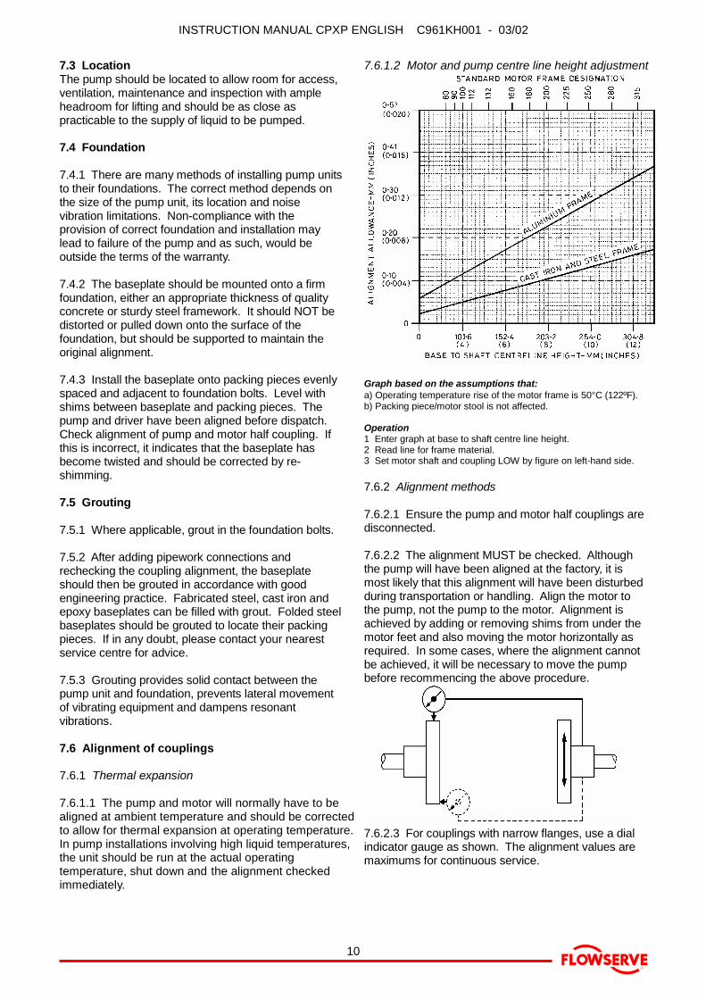
7.6.1.2 Motor and pump centre line height adjustment
Graph based on the assumptions that:a) Operating temperature rise of the motor frame is 50°C (122ºF).b) Packing piece/motor stool is not affected.
Operation1 Enter graph at base to shaft centre line height.2 Read line for frame material.3 Set motor shaft and coupling LOW by figure on left-hand side.
7.6.2 Alignment methods
7.6.2.1 Ensure the pump and motor half couplings aredisconnected.
7.6.2.2 The alignment MUST be checked. Althoughthe pump will have been aligned at the factory, it ismost likely that this alignment will have been disturbedduring transportation or handling. Align the motor tothe pump, not the pump to the motor. Alignment isachieved by adding or removing shims from under themotor feet and also moving the motor horizontally asrequired. In some cases, where the alignment cannotbe achieved, it will be necessary to move the pumpbefore recommencing the above procedure.
7.6.2.3 For couplings with narrow flanges, use a dialindicator gauge as shown. The alignment values aremaximums for continuous service.

INSTRUCTION MANUAL CPXP ENGLISH C961KH001 - 03/02
®
11
7.6.2.4 Permissible misalignment limits at workingtemperature• Parallel alignment
- 0.25mm (0.010in) TIR maximum• Angular alignment
- 0.3mm (0.012in) TIR maximum for couplingsnot exceeding 100mm (4in) flange diameter- 0.5mm (0.020in) TIR maximum for couplingsover 100mm (4in) diameter
7.6.2.5 When checking parallel alignment, the totalindicator read-out (TIR) shown is twice the value of theactual shaft displacement.
7.7 Electrical connections
7.7.1 � Electrical connections should be madeby a qualified Electrician in accordance with therelevant local national and international regulations.
7.7.2 It is important to be aware of the EUROPEANDIRECTIVE on electromagnetic compatibility whenwiring up and installing equipment on site.
Attention must be paid to ensure that the techniquesused during wiring/installation do not increaseelectromagnetic emissions or decrease theelectromagnetic immunity of the equipment, wiring orany connected devices. If in any doubt contactFlowserve for advice.
7.7.3 � The motor must be wired up inaccordance with the motor manufacturer's instructions(normally supplied within the terminal box) includingany temperature, earth leakage, current and otherprotective devices as appropriate. The identificationnameplate should be checked to ensure the powersupply is appropriate.
7.7.4 �A device to provide emergency stopping shall be fitted.
7.7.5 If not supplied pre-wired to the pump unit thecontroller/starter electrical details will also be suppliedwithin the controller/starter.
7.7.6 For electrical details on pump sets withcontrollers see the wiring diagram.
7.7.7 � WARNING:See paragraphs on 'direction of rotation' beforeconnecting the motor to the electrical supply.
7.8 Pipework connections
7.8.1 Protective covers are fitted to the pipeconnections to prevent foreign bodies entering duringtransportation and installation. Ensure that thesecovers are removed from the pump before connectingany pipes.
7.8.2 Maximum forces and moments allowed on thepump flanges vary with the pump size and type. Tominimise these forces and moments that may cause
misalignment, hot bearings, worn couplings, vibrationand the possible failure of the pump casing, thefollowing points should be strictly followed:• Prevent excessive external pipe load.• Never draw piping into place by applying force to
pump flange connections.• Do not mount expansion joints so that their force, due
to internal pressure, acts on the pump flange.
7.8.3 The inlet pipe should be as short as possible,airtight and the smallest volume as practical for thepump flow rate.
It is recommended that the pump inlet pipe is no largerthan the pump inlet bore or such that the suctionvelocity is in the range of 3 to 5m/sec (10 to 16ft/sec).The piping should be inclined up towards the pumpinlet.
7.8.4 Allow a minimum of two pipe diameters ofstraight section between the elbow and inlet flange.Use of an inlet strainer is not recommended as this canprevent the priming process.
7.8.5 Fitting an isolator and non-return valves canallow easier maintenance. Never throttle pump onsuction side and never place a valve directly on thepump inlet nozzle.
7.8.6 If a non-return valve is located in the dischargepipework then a vent/bleed pipe should be fitted fromthe discharge pipe back to the sump or source tank.
7.8.7 A regulating valve should be fitted in thedischarge pipework, unless pump flow is controlled bythe delivery system design.
7.8.8 The delivery pipework must permit priming air toescape unhindered from the pump during the primingcycle, without back pressure and prevent excessiverun-back of liquid on shutdown to minimise syphoning.Priming air may be vented in one of the following ways:
1) The discharge pipework regulating valve, if fitted,may be partly opened during the priming cycle tofreely vent the air.
2) An automatic air release valve may be fitted to thedischarge pipework, between the pump and anyvalves, providing that gases and vapours given offare environmentally safe and acceptable forrelease into the atmosphere.
3) An air bleed pipe may be run from the dischargepipework, between the pump and any valves, backto the suction tank or sump. This arrangement hasa disadvantage in that normal manual/automaticcontrol will be necessary during operation in orderto prevent continuous recirculation of the pumpedliquid.
7.8.9 Piping and fittings should be flushed before use.
7.8.10 Piping for corrosive liquids should be arrangedto allow pump flushing before removal of a unit.

INSTRUCTION MANUAL CPXP ENGLISH C961KH001 - 03/02
®
12
7.9 Final piping check
7.9.1 After connecting piping to the pump, rotate theshaft several times by hand to ensure there is nobinding and all parts are free.
7.9.2 Recheck the coupling alignment, as previouslydescribed, to ensure no pipe strain. If pipe strainexists, correct piping.
7.10 Auxiliary piping
7.10.1 The connections which are to be piped up willhave been fitted with protective metal or plastic plugswhich will need to be removed.
7.10.2 Pumps fitted with packed glandsWhen suction pressure is below ambient pressure anddifferential head is less than 10m (32.8ft), it may benecessary to feed gland packing with liquid to providelubrication and prevent the ingress of air.
7.10.3 Pumps fitted with mechanical seals
7.10.3.1 The conical design of the single internal sealhousing provides excellent liquid circulation around theseal and will not normally require a separate flush.
7.10.3.2 Single seals requiring re-circulation willnormally be provided with the auxiliary piping frompump casing already fitted.
7.10.3.3 Flowserve seal connections are designatedas follows:
Q - quenchF - flushD - drain outletBI - barrier fluid in (double seals)BO - barrier fluid out (double seals)H - heating jacketC - cooling jacket
7.10.3.4 Seal housings/covers having an auxiliaryquench connection, require connection to a suitablesource of liquid flow, low pressure steam or staticpressure from a header tank. Recommended pressureis 0.35 bar (5psi) or less.
7.10.3.5 Double seals require a barrier liquid betweenthe seals, compatible with the pumped liquid.
7.10.3.6 With back-to-back double seals, the barrierliquid should be at a minimum pressure of 1 bar(14.5psi) above the maximum pressure on the pumpside of the inner seal. The barrier liquid pressure mustnot exceed limitations of the seal on the atmosphericside. For toxic service the barrier liquid supply anddischarge must be in a safe area.
7.10.3.7 Seal chamber pressure v generated headMECHANICAL
SEALUse seal manufacturer's limits or ask seal
manufacturer to verify seal pressure
GLANDPACKING
Maximum stuffing box pressure =5 bar (3500rpm), 7 bar (2900rpm) and
10 bar (1450 & 1750rpm)
NOTES:a) Total seal pressure is equal to pressure at seal plus suction
pressure.b) For pumped liquid viscosities greater than 440 Centistokes
multiply the generated pressure by 1.25 for 125, 160 and200 size pumps and by 2.0 for larger sizes.
c) Differential pressure in bar equals head in metres multipliedby specific gravity all divided by 10.19.
d) For psi multiply the pressure in bar by 14.504.
7.10.3.8 Special seals may require modification toauxiliary piping described above. Consult Flowserve ifunsure of correct method or arrangement.
7.10.3.9 For pumping hot liquids, to avoid sealdamage, it is recommended that any externalflush/cooling supply be continued after stopping thepump.
7.10.3.10 Tandem seals require a barrier liquidbetween the seals that is compatible with the pumpedliquid.
7.10.4 Pumps fitted with heating/cooling jacketsConnect the heating/cooling pipes from the site supply.The top connection should be used as the outlet toensure complete filling/venting of the annulus.
8 MAKING READY FOR OPERATION
8.1 Lubrication
8.1.1 Determine the mode of lubrication of the pumpset, eg grease, oil, product lubrication etc.
8.1.2 � For oil lubricated pumps, fill the bearinghousing with the correct grade of oil to the correctlevel, ie sight glass or constant level oiler bottle.
8.1.2.1 When fitted with a constant level oiler, thebearing housing should be filled by unscrewing orhinging back the transparent bottle and filling thebottle with oil. Where an adjustable body Denco oileris fitted this should be set to the height shown in thefollowing diagram.
INSTRUCTION MANUAL CPXP ENGLISH C961KH001 - 03/02
®
13
The oil filled bottle should then be refitted so as toreturn it to the upright position. Filling of the bottleshould be repeated until oil remains visible within thebottle.
8.1.3 To fill the bearing housing with oil, unscrew theoil filler/breather and fill through the orifice.
8.1.4 Grease lubricated pumps and electric motors aresupplied pre-greased.
8.1.5 Other drivers and gearboxes, if appropriate,should be lubricated in accordance with their manuals.
8.2 Direction of rotation
8.2.1 � Serious damage can result if the pump isstarted or run in the wrong direction of rotation.
8.2.2 � The pump is shipped with the couplingelement removed. Ensure the direction of rotation ofthe motor is correct before fitting the coupling element.Direction of rotation must correspond to the directionarrow.
8.2.3 � If maintenance work has been carried outto the site's electricity supply, the direction of rotationshould be re-checked as above in case the supplyphasing has been altered.
8.3 Guarding
� Guarding is supplied fitted to the pumpset. If this has been removed or disturbed ensure thatall the protective guards are securely refitted.
8.4 Open impeller clearanceThe impeller clearance is set in the factory. This mayrequire adjustment because of piping attachment orincrease in temperatures. For setting instructions referto the Preventative Maintenance and Servicing sectionof this book.
8.5 � Primary and auxiliary suppliesEnsure all electrical, hydraulic, pneumatic, sealant andlubrication systems (as applicable) are connected andoperational.
8.6 Filling and self priming
8.6.1 � Fill the pump with liquid to be pumped, orcompatible liquid, via the filling plug, before startingcontinuous duty operation.
8.6.2 The pump has self priming action for which aseparate air pump or foot valve or non-return valve isnot normally required.
9 STARTING AND RUNNING THE PUMP
9.1 � Ensure flushing and/or cooling/heatingliquid supplies are turned ON, before starting pump.
9.2 CLOSE the outlet valve.
9.3 OPEN all inlet valves.
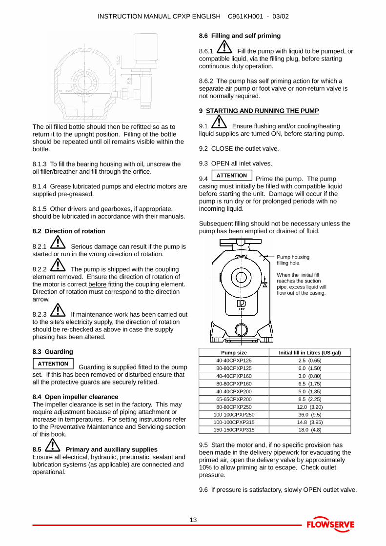
9.4 � Prime the pump. The pumpcasing must initially be filled with compatible liquidbefore starting the unit. Damage will occur if thepump is run dry or for prolonged periods with noincoming liquid.
Subsequent filling should not be necessary unless thepump has been emptied or drained of fluid.
Pump housingfilling hole.
When the initial fillreaches the suctionpipe, excess liquid willflow out of the casing.
Pump size Initial fill in Litres (US gal)40-40CPXP125 2.5 (0.65)80-80CPXP125 6.0 (1.50)40-40CPXP160 3.0 (0.80)80-80CPXP160 6.5 (1.75)40-40CPXP200 5.0 (1.35)65-65CPXP200 8.5 (2.25)80-80CPXP250 12.0 (3.20)
100-100CPXP250 36.0 (9.5)100-100CPXP315 14.8 (3.95)150-150CPXP315 18.0 (4.8)
9.5 Start the motor and, if no specific provision hasbeen made in the delivery pipework for evacuating theprimed air, open the delivery valve by approximately10% to allow priming air to escape. Check outletpressure.
9.6 If pressure is satisfactory, slowly OPEN outlet valve.

INSTRUCTION MANUAL CPXP ENGLISH C961KH001 - 03/02
®
14
9.7 It is recommended that the priming time is noted.Priming times in excess of 5 minutes will indicate apump or system fault. Any noticeable increases inpriming time on subsequent starts will also indicate afault. Irregular use could lead to the danger of'evaporation' of the priming fluid.
9.8 � Do not run the pump with the outlet valveclosed for a period longer than 30 seconds.
9.9 If the pump has to self prime the system it maytake a short time before the outlet is pressurised.
9.10 If NO pressure, or LOW pressure, STOP thepump. Refer to fault finding chart for fault diagnosis.
9.11 Running pumps fitted with packed glands
9.11.1 If the pump has a packed gland there must besome leakage from the gland. Gland nuts should initiallybe finger-tight only. Leakage should take place soonafter the stuffing box is pressurised. If no leakage takesplace the packing will begin to overheat. If overheatingtakes place the pump should be stopped and allowed tocool before being re-started. When the pump is re-started it should be checked to ensure leakage is takingplace at the packed gland.
9.11.2 If hot liquids are being pumped it may benecessary to slacken the gland nuts to achieve leakage.
9.11.3 The pump should be run for ten minutes withsteady leakage and the gland nuts tightened by 10degrees at a time until leakage is reduced to anacceptable level, normally 30 to 120 drops per minute.Bedding in of the packing may take another 15minutes.
9.12 Running pumps fitted with mechanical seals
9.12.1 Mechanical seals require no adjustment. Anyslight initial leakage will stop when the seal is run in.Seals will always leak in operation.
9.12.2 Before pumping dirty liquids, it is advisable, ifpossible, to run the pump in using clean liquid tosafeguard the seal face.
9.12.3 � For external flush or quench, this shouldbe started before the pump is run and allowed to flowfor a period after the pump has stopped.
9.13 Stop/start frequencyGenerally 6 stop/starts per hour may be satisfactory.Refer frequent stop/starting to motor manufacturer.
STANDBY PUMPS SHOULD BE RUN ALTERNATELY.
10 STOPPING AND SHUTDOWN
10.1 Close the outlet valve, but ensure that the pumpruns in this condition for no more than a few seconds.
10.2 Stop the pump.
10.3 Switch off flushing and/or cooling/ heating liquidsupplies at a time appropriate to the process.
10.4 � For prolonged shut-downs and especiallywhen ambient temperatures are likely to drop belowfreezing point, the pump and any cooling and flushingarrangements must be drained or otherwise protected.
11 PREVENTATIVE MAINTENANCE & SERVICING
11.1 Maintenance scheduleOur specialist service personnel can help withpreventative maintenance records and providecondition monitoring for temperature and vibration toidentify the onset of potential problems.
11.2 Routine inspection (daily/weekly)The following checks should be made and theappropriate action taken to remedy any deviations:• Check operating behaviour; ensure noise,
vibration and bearing temperatures are normal.• Check that there are no abnormal fluid or lubricant
leaks (static and dynamic seals) and that anysealant systems (if fitted) are full and operatingnormally.
• Check that shaft seal leaks are within acceptablelimits.
• Check the level and condition of oil lubricant. Ongrease lubricated pumps, check running hourssince last recharge of grease or complete greasechange.
• Check any auxiliary supplies eg heating/cooling (iffitted) are functioning correctly.
• Refer to the manuals of any associated equipmentfor routine checks needed.
11.3 Periodic inspection (6 monthly)• Check foundation bolts for security of attachment
and corrosion.• Check pump running records for hourly usage to
determine if bearing lubricant requires changing.• The coupling should be checked for correct
alignment and worn driving elements.• Refer to the manuals of any associated equipment
for periodic checks needed.
11.4 Lubrication data
11.4.1 Oil lubricated bearings• Normal oil change intervals are 4000 operating
hours. For pumps on hot service or in severelydamp or corrosive atmosphere, the oil will requirechanging more frequently. Lubricant and bearingtemperature analysis can be useful in optimisinglubricant change intervals.
• The lubricating oil should be a high quality oil havingoxidisation and foam inhibitors, or synthetic oil.
• The bearing temperature may be allowed to rise to50°C (122ºF) above ambient, but should notexceed 82°C (180ºF), API 610 limit. A continuouslyrising temperature, or an abrupt rise, indicate afault.
INSTRUCTION MANUAL CPXP ENGLISH C961KH001 - 03/02
®
15
• Pumps which handle high temperature liquids mayrequire their bearings to be cooled to preventbearing temperatures exceeding their limits.
11.4.2 Grease lubricated bearings
11.4.2.1 When grease nipples are fitted, one chargebetween grease changes is advisable for mostoperating conditions; ie 2000 hours interval.
11.4.2.2 Normal intervals between grease changes are4000 hours. The characteristics of the installation andseverity of service will determine the frequency oflubrication. Lubricant and bearing temperatureanalysis can be useful in optimising lubricant changeintervals.
11.4.2.3 For most operating conditions, a qualitygrease having a lithium soap base and NLGIconsistency of No.2 or No.3 is recommended. Thedrop point should exceed 175°C (347°C).
11.4.2.4 � WARNING:Never mix greases containing different bases,thickeners or additives.
11.5 Gland packing
11.5.1 The stuffing box split gland can be completelyremoved for re-packing or to enable the addition ofextra rings of packing.
11 5.2 The stuffing box is normally supplied with alantern ring to enable a clean or pressurised flush tothe centre of the packing. If not required, this can bereplaced by an extra 2 rings of packing.
11.6 Mechanical sealsWhen leakage becomes unacceptable the seal willneed replacement.
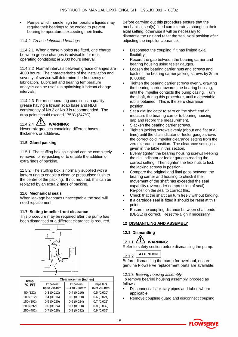
11.7 Setting impeller front clearanceThis procedure may be required after the pump hasbeen dismantled or a different clearance is required.
Clearance mm (inches)Temp.ºC (ºF) Impellers
up to 210mmImpellers
211 to 260mmImpellers
over 260mm50 (122)100 (212)150 (302)200 (392)250 (482)
0.3 (0.012)0.4 (0.016)0.5 (0.020)0,6 (0.024)0.7 (0.028)
0.4 (0.016)0.5 (0.020)0.6 (0.024)0.7 (0.028)0.8 (0.032)
0.5 (0.020)0.6 (0.024)0.7 (0.028)0.8 (0.032)0.9 (0.036)
Before carrying out this procedure ensure that themechanical seal(s) fitted can tolerate a change in theiraxial setting, otherwise it will be necessary todismantle the unit and reset the seal axial position afteradjusting the impeller clearance.
• Disconnect the coupling if it has limited axialflexibility.
• Record the gap between the bearing carrier andbearing housing using feeler gauges.
• Loosen the bearing carrier nuts and screws andback off the bearing carrier jacking screws by 2mm(0.080in).
• Tighten the bearing carrier screws evenly, drawingthe bearing carrier towards the bearing housing,until the impeller contacts the pump casing. Turnthe shaft, during this procedure, until a detectablerub is obtained. This is the zero clearanceposition.
• Set a dial indicator to zero on the shaft end ormeasure the bearing carrier to bearing housinggap and record the measurement.
• Slacken the bearing carrier screws.• Tighten jacking screws evenly (about one flat at a
time) until the dial indicator or feeler gauge showsthe correct cold impeller clearance setting from thezero clearance position. The clearance setting isgiven in the table in this section.
• Evenly tighten the bearing housing screws keepingthe dial indicator or feeler gauges reading thecorrect setting. Then tighten the hex nuts to lockthe jacking screws in position.
• Compare the original and final gaps between thebearing carrier and housing to check if themovement of the shaft has exceeded the sealcapability (over/under compression of seal).Re-position the seal to correct this.
• Check that the shaft can turn freely without binding.• If a cartridge seal is fitted it should be reset at this
point.• Ensure the coupling distance between shaft ends
(DBSE) is correct. Reset/re-align if necessary.
12 DISMANTLING AND ASSEMBLY
12.1 Dismantling
12.1.1 � WARNING:Refer to safety section before dismantling the pump.
12.1.2 �Before dismantling the pump for overhaul, ensuregenuine Flowserve replacement parts are available.
12.1.3 Bearing housing assemblyTo remove bearing housing assembly, proceed asfollows:• Disconnect all auxiliary pipes and tubes where
applicable.• Remove coupling guard and disconnect coupling.
INSTRUCTION MANUAL CPXP ENGLISH C961KH001 - 03/02
®
16
• If oil lubricated frame, drain oil by removing drainplug.
• Record the gap between the bearing carrier andbearing housing so that this setting can be usedduring workshop assembly.
• Place hoist sling through bearing housing window.• Remove casing screws.• Remove bearing housing assembly from pump
casing.• The two threaded holes in the bearing housing
flange can be used for jacking screws to assistwith removal.
• Remove pump casing gasket 4590/1 and discard.A replacement gasket will be required forassembly. Clean gasket mating surfaces.
• On diffuser casing sizes it is not normallynecessary to remove the diffuser 1410, 4590/2 and9906/5.
12.1.4 Impeller removal
� NEVER APPLY HEAT TO REMOVETHE IMPELLER. TRAPPED OIL OR LUBRICANTMAY CAUSE AN EXPLOSION.
• Fit a chain wrench or bolt a bar to the holes in thecoupling half, or fit a keyed shaft wrench directly tothe shaft.
• Using gloved hands, raise the wrench above thework bench by turning the impeller clockwise asviewed from the impeller end of the shaft.
• Give the impeller a quick turn counter-clockwise tostrike the wrench handle against the work benchsurface or a wooden block. This will free theimpeller from the shaft.
• The loosened impeller has an O-ring that shouldbe discarded. A new O-ring will be required forassembly.
12.1.6 Seal housing and sealThe seal manufacturer's instructions should befollowed for dismantling and assembly, but thefollowing guidance should assist with most seal types:• Remove the seal housing screws.• Remove the seal cover nuts, if a separate seal
cover is fitted, and slide the seal cover away.• Loosen the grub screws (used in most mechanical
seals).• Carefully pull off the seal housing and mechanical
seal rotating element(s). Remove the seal cover.• Remove shaft sleeve (if fitted).• On non-cartridge seals the stationary seat remains
in the seal housing/cover with its sealing member.Remove only if damaged or worn out.
• On pumps fitted with gland packing, the packingand lantern ring should be removed only if thepacking is to be replaced.
12.1.6 Bearing housing• Pull off the pump half of coupling and remove
coupling key.• Remove support foot.
• Remove the pump side liquid flinger and/orlabyrinth seal rotary half (depending on optionfitted).
• Slacken the nuts and remove bearing carrierscrews.
• Tighten bearing carrier jacking screws evenly toinitiate bearing carrier release.
• Remove bearing carrier and shaft assembly fromthe bearing housing by pulling it towards thecoupling end.
• Remove bearing circlip (or bearing carrier lockingring if paired angular contact bearings are fitted).NOTE: Bearing carrier locking rings are left-handthreaded.
• Remove drive side liquid flinger and/or labyrinthseal rotary half (depending on option fitted).
• Remove bearing carrier.• Remove pump side bearing.• Release the self locking drive side bearing nut and
remove drive side bearing.• When pressing bearings off the shaft, use force on
the inner race only.
12.2 Examination of parts
12.2.1 Used parts must be inspected before assemblyto ensure the pump will subsequently run properly. Inparticular, fault diagnosis is essential to enhance pumpand plant reliability.
12.2.2 Casing, seal housing and impellerInspect for excessive wear, pitting, corrosion, erosionor damage and any sealing surface irregularities.Replace as necessary.
12.2.3 Shaft and sleeve (if fitted)Replace if grooved or pitted. With the bearingmounting diameters (or bearing outer) supported by'V' blocks, check that the shaft runouts are within0.025mm (0.001in) at the coupling end and 0.050mm(0.002in) at the sleeve end.
12.2.4 Gaskets and O-ringsAfter dismantling, discard and replace.
12.2.5 BearingsIt is recommended that bearings are not re-used afterany removal from the shaft.
12.2.6 Bearing isolators, labyrinths or lip seals (iffitted)• The lubricant, bearings and bearing housing seals
are to be inspected for contamination and damage.If oil bath lubrication is utilised, these provideuseful information on operating conditions withinthe bearing housing. If bearing damage is not dueto normal wear and the lubricant contains adversecontaminants, the cause should be correctedbefore the pump is returned to service.
• Labyrinth seals and bearing isolators should beinspected for damage but are normally non-wearing parts and can be re-used.

INSTRUCTION MANUAL CPXP ENGLISH C961KH001 - 03/02
®
17
• Bearing seals are not totally leak free devices.Oil from these may cause staining adjacent to thebearings.
12.2.7 Bearing housing and carrierInspect the bearing carrier circlip groove, ensure it isfree from damage and that housing lubricationpassages are clear. Replace grease nipples or thefilter breather (where fitted) if damaged or clogged.On oil lubricated versions, the oil level sight glassshould be replaced if oil stained.
12.3 Assembly
12.3.1 To assemble the pump consult the sectionaldrawings.
12.3.2 Ensure threads, gasket and O-ring matingfaces are clean. Apply thread sealant to non-facesealing pipe thread fittings.
12.3.3 Bearing housing and rotating element assembly• Clean the inside of the bearing housing, bearing
carrier and bores for bearings.• Attach bearing housing support foot.• Press drive side bearing(s) on to shaft.• The double row thrust bearing will not normally
have a single filling slot, as such bearings arelimited to taking thrust in only one direction. If sucha bearing replacement is used, it must bepositioned on the shaft so that the bearing fillingslot faces the impeller end of the shaft.
• If duplex bearings are to be fitted, these must bemounted back-to-back, as shown below.
Nilos ring (clearance type) is only fitted on grease lubricatedoption units
• The following methods are recommended for fittingthe bearings onto the shaft:Method 1 - Use a hotplate, hot bath, oven orinduction heater to heat the bearing race so it caneasily be placed in position then allowed to shrinkand grip the shaft. It is important that thetemperature is not raised above 100ºC (212ºF).Method 2 - Press the bearing onto the shaft usingequipment that can provide a steady, even load tothe inner race. Care is to be taken to avoiddamage to the bearing and shaft.
• With bearings at ambient temperature, screw onthe drive side self-locking bearing nut (with itspolyamide insert facing away from the bearing)until tight.
• With double row thrust bearings place the innerbearing circlip over the shaft with the tapered facefacing the impeller end.
• With the heavy duty bearing option, the locking ringshould be placed between the bearings with theface marked 'left-hand thread' facing the impellerend.
• Press pump side bearing onto the shaft usingmethod 1 or 2 above.
• With the NUP roller bearing option, the loose ringshould be against the shaft shoulder.
• Fit O-ring on the bearing carrier. Lightly lubricatethe bearing carrier bore and O-ring.
• If a separate labyrinth type bearing housing seal isused there may be a drain hole that should be atthe 6 o'clock position facing the bearing.
• Fit drive side radial lip seal (if fitted) into thebearing carrier, having filled the position betweenthe two lips with grease.
• Ensure the shaft keyway edges are free of burrs.During installation, use shimming or tape over thekeyway to avoid damaging the drive side bearingseals
• Slide the bearing carrier onto the shaft/bearingassembly and insert inner circlip into the carriergroove or screw up the bearing locking ring.
• On grease lubricated pumps, pump grease throughthe grease nipple in the bearing carrier until greaseis visible in the bearing races.
• Check shaft for free rotation.• Fit the pump side labyrinth into the bearing housing
ensuring the drain hole faces the bearing and is atthe 6 o'clock position.
• Install the shaft assembly into the bearing housinguntil gap is approximately 5mm (0.2in).
• Fit the bearing carrier screws but do not tighten.• Press drive side liquid flinger and pump side liquid
flinger onto shaft where applicable. These shouldbe set 0.5 to 2mm (0.02 to 0.08in) (light contact forelastomer type) from the bearing carrier andbearing housing respectively.
• The pump side flinger (this feature is integral withsome proprietary labyrinth seals) should only beset in its final position after setting the shaft axialposition.
INSTRUCTION MANUAL CPXP ENGLISH C961KH001 - 03/02
®
18
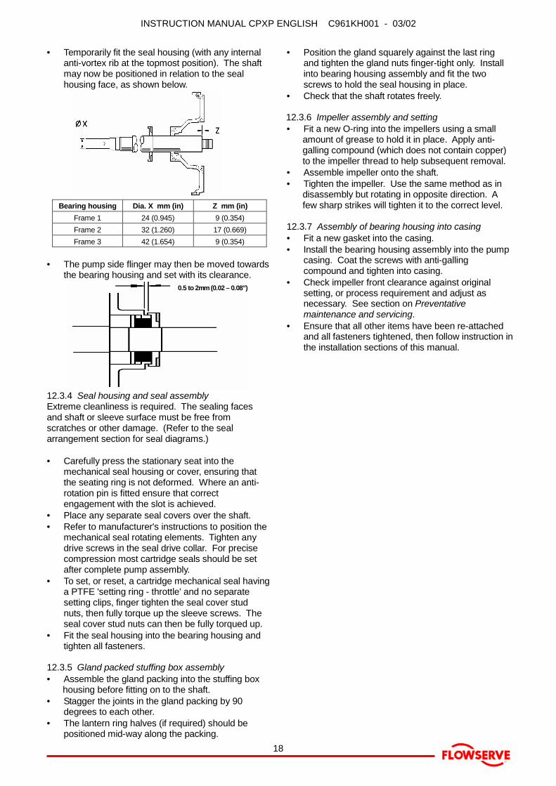
• Temporarily fit the seal housing (with any internalanti-vortex rib at the topmost position). The shaftmay now be positioned in relation to the sealhousing face, as shown below.
Bearing housing Dia. X mm (in) Z mm (in)Frame 1 24 (0.945) 9 (0.354)Frame 2 32 (1.260) 17 (0.669)Frame 3 42 (1.654) 9 (0.354)
• The pump side flinger may then be moved towardsthe bearing housing and set with its clearance.
0.5 to 2mm (0.02 – 0.08”)
12.3.4 Seal housing and seal assemblyExtreme cleanliness is required. The sealing facesand shaft or sleeve surface must be free fromscratches or other damage. (Refer to the sealarrangement section for seal diagrams.)
• Carefully press the stationary seat into themechanical seal housing or cover, ensuring thatthe seating ring is not deformed. Where an anti-rotation pin is fitted ensure that correctengagement with the slot is achieved.
• Place any separate seal covers over the shaft.• Refer to manufacturer's instructions to position the
mechanical seal rotating elements. Tighten anydrive screws in the seal drive collar. For precisecompression most cartridge seals should be setafter complete pump assembly.
• To set, or reset, a cartridge mechanical seal havinga PTFE 'setting ring - throttle' and no separatesetting clips, finger tighten the seal cover studnuts, then fully torque up the sleeve screws. Theseal cover stud nuts can then be fully torqued up.
• Fit the seal housing into the bearing housing andtighten all fasteners.
12.3.5 Gland packed stuffing box assembly• Assemble the gland packing into the stuffing box
housing before fitting on to the shaft.• Stagger the joints in the gland packing by 90
degrees to each other.• The lantern ring halves (if required) should be
positioned mid-way along the packing.
• Position the gland squarely against the last ringand tighten the gland nuts finger-tight only. Installinto bearing housing assembly and fit the twoscrews to hold the seal housing in place.
• Check that the shaft rotates freely.
12.3.6 Impeller assembly and setting• Fit a new O-ring into the impellers using a small
amount of grease to hold it in place. Apply anti-galling compound (which does not contain copper)to the impeller thread to help subsequent removal.
• Assemble impeller onto the shaft.• Tighten the impeller. Use the same method as in
disassembly but rotating in opposite direction. Afew sharp strikes will tighten it to the correct level.
12.3.7 Assembly of bearing housing into casing• Fit a new gasket into the casing.• Install the bearing housing assembly into the pump
casing. Coat the screws with anti-gallingcompound and tighten into casing.
• Check impeller front clearance against originalsetting, or process requirement and adjust asnecessary. See section on Preventativemaintenance and servicing.
• Ensure that all other items have been re-attachedand all fasteners tightened, then follow instruction inthe installation sections of this manual.
INSTRUCTION MANUAL CPXP ENGLISH C961KH001 - 03/02
®
19
13 SEALING ARRANGEMENTS
This Section shows details of the seal arrangements.Refer also to section on auxiliary piping in thismanual. Contact your nearest Flowserve sales officeor service centre if you require further information orare unsure of the specific arrangement supplied.
13.1 Single seal types
13.1.1 Single stepped balanced seal
Note: “L1K” and “L1N” are seal lengthsdefined within seal standard DIN 24960.
13.1.2 Single unbalanced (or inherently balanced)seal
VARIANTSSelf setting collarSeparate seal drive collar, set to Dimension ‘X’.Integral seal drive collar with screws, set to Dimension ‘X’.
Bearing housing Setting dimensionX Y
Frame 1 23.5 11.0Frame 2 34.0 19.0Frame 3 33.5 11.0
13.1.3 Single seal with external neck bush
Q - Rp 1/4" quenchD - Rp 1/4" drainF - Rp 1/4" flush
Bearing housing Setting dimensionX Y
Frame 1 23.5 11.0Frame 2 34.0 19.0Frame 3 33.5 11.0
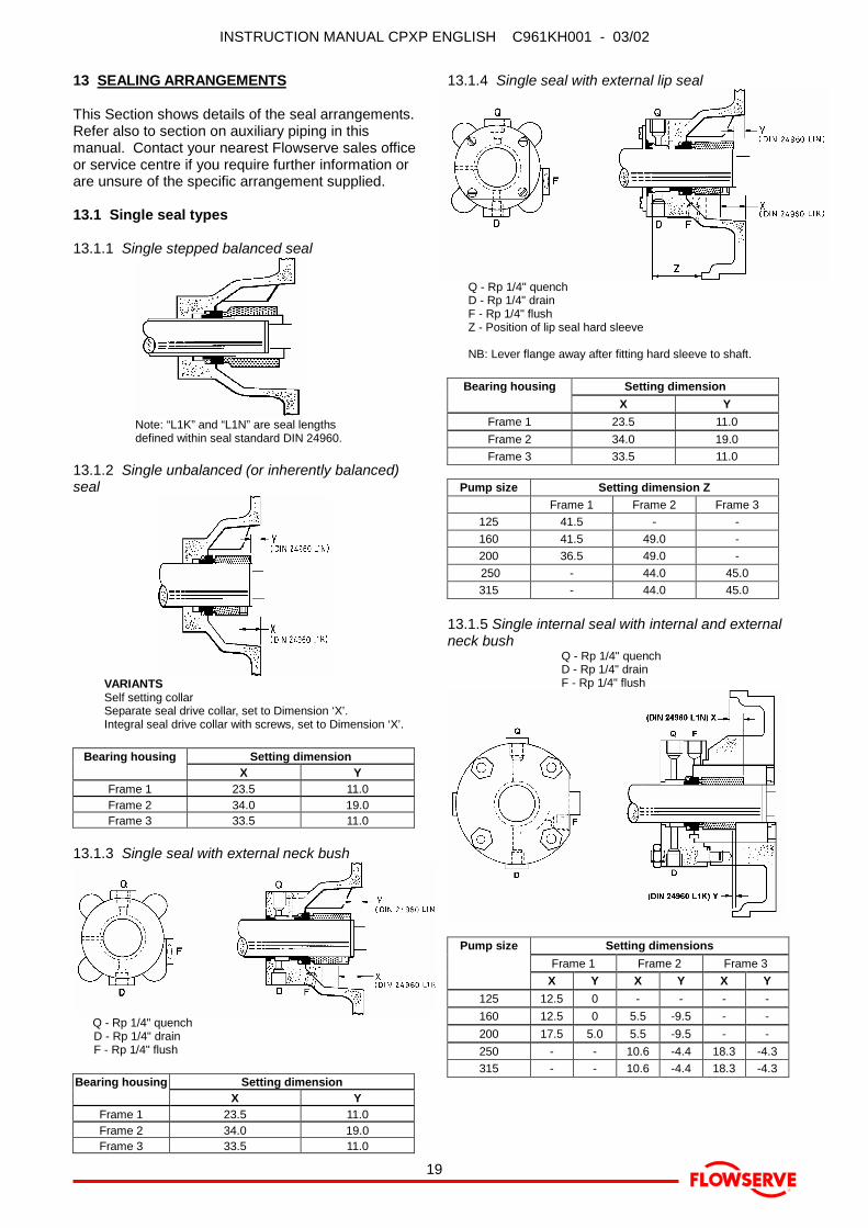
13.1.4 Single seal with external lip seal
Q - Rp 1/4" quenchD - Rp 1/4" drainF - Rp 1/4" flushZ - Position of lip seal hard sleeve
NB: Lever flange away after fitting hard sleeve to shaft.
Bearing housing Setting dimensionX Y
Frame 1 23.5 11.0Frame 2 34.0 19.0Frame 3 33.5 11.0
Pump size Setting dimension ZFrame 1 Frame 2 Frame 3
125 41.5 - -160 41.5 49.0 -200 36.5 49.0 - 250 - 44.0 45.0315 - 44.0 45.0
13.1.5 Single internal seal with internal and externalneck bush
Q - Rp 1/4" quenchD - Rp 1/4" drainF - Rp 1/4" flush
Pump size Setting dimensionsFrame 1 Frame 2 Frame 3
X Y X Y X Y125 12.5 0 - - - -160 12.5 0 5.5 -9.5 - -200 17.5 5.0 5.5 -9.5 - -250 - - 10.6 -4.4 18.3 -4.3315 - - 10.6 -4.4 18.3 -4.3
INSTRUCTION MANUAL CPXP ENGLISH C961KH001 - 03/02
®
20
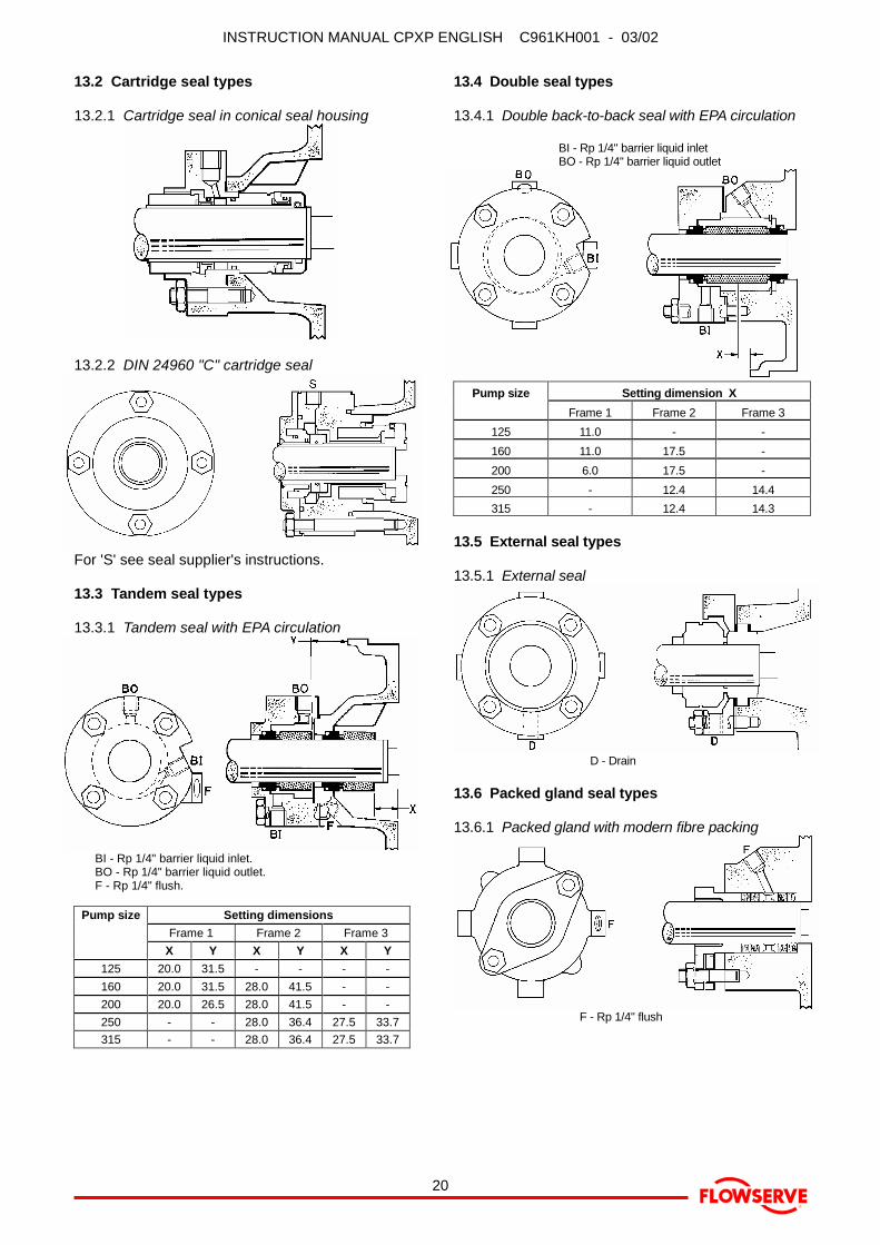
13.2 Cartridge seal types
13.2.1 Cartridge seal in conical seal housing
13.2.2 DIN 24960 "C" cartridge seal
For 'S' see seal supplier's instructions.
13.3 Tandem seal types
13.3.1 Tandem seal with EPA circulation
BI - Rp 1/4" barrier liquid inlet.BO - Rp 1/4" barrier liquid outlet.F - Rp 1/4" flush.
Pump size Setting dimensionsFrame 1 Frame 2 Frame 3
X Y X Y X Y125 20.0 31.5 - - - -160 20.0 31.5 28.0 41.5 - -200 20.0 26.5 28.0 41.5 - -250 - - 28.0 36.4 27.5 33.7315 - - 28.0 36.4 27.5 33.7
13.4 Double seal types
13.4.1 Double back-to-back seal with EPA circulation
BI - Rp 1/4" barrier liquid inletBO - Rp 1/4" barrier liquid outlet
Pump size Setting dimension XFrame 1 Frame 2 Frame 3
125 11.0 - -160 11.0 17.5 -200 6.0 17.5 -250 - 12.4 14.4315 - 12.4 14.3
13.5 External seal types
13.5.1 External seal
D - Drain
13.6 Packed gland seal types
13.6.1 Packed gland with modern fibre packing
F - Rp 1/4" flush
INSTRUCTION MANUAL CPXP ENGLISH C961KH001 - 03/02
®
21
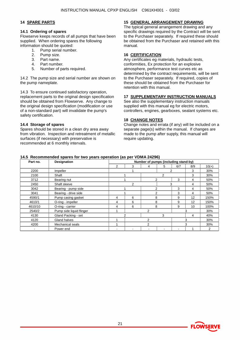
14 SPARE PARTS
14.1 Ordering of sparesFlowserve keeps records of all pumps that have beensupplied. When ordering spares the followinginformation should be quoted:
1. Pump serial number.2. Pump size.3. Part name.4. Part number.5. Number of parts required.
14.2 The pump size and serial number are shown onthe pump nameplate.
14.3 To ensure continued satisfactory operation,replacement parts to the original design specificationshould be obtained from Flowserve. Any change tothe original design specification (modification or useof a non-standard part) will invalidate the pump'ssafety certification.
14.4 Storage of sparesSpares should be stored in a clean dry area awayfrom vibration. Inspection and retreatment of metallicsurfaces (if necessary) with preservative isrecommended at 6 monthly intervals.
15 GENERAL ARRANGEMENT DRAWINGThe typical general arrangement drawing and anyspecific drawings required by the Contract will be sentto the Purchaser separately. If required these shouldbe obtained from the Purchaser and retained with thismanual.
16 CERTIFICATIONAny certificates eg materials, hydraulic tests,conformities, Ex protection for an explosiveatmosphere, performance test curves etc asdetermined by the contract requirements, will be sentto the Purchaser separately. If required, copies ofthese should be obtained from the Purchaser forretention with this manual.
17 SUPPLEMENTARY INSTRUCTION MANUALSSee also the supplementary instruction manualssupplied with this manual eg for electric motors,controllers, engines, gearboxes, sealant systems etc.
18 CHANGE NOTESChange notes and errata (if any) will be included on aseparate page(s) within the manual. If changes aremade to the pump after supply, this manual willrequire updating.
14.5 Recommended spares for two years operation (as per VDMA 24296)Part no. Designation Number of pumps (including stand-by)
2 3 4 5 6/7 8/9 10(+)2200 Impeller 1 2 3 30%2100 Shaft 1 2 3 30%3712 Bearing nut 1 2 3 4 50%2450 Shaft sleeve 2 3 4 50%3042 Bearing - pump side 1 2 3 4 50%3041 Bearing - drive side 1 2 3 4 50%
4590/1 Pump casing gasket 4 6 8 9 12 150%4610/1 O-ring - impeller 4 6 8 9 12 150%
4610/10 O-ring - carrier 4 6 8 9 10 100%2540/2 Pump side liquid flinger 1 2 3 30%4130 Gland Packing - set 2 3 4 40%4120 Gland halves 1 2 3 30%4200 Mechanical seals 1 2 3 30%
- Power end - - - - - 1 2

INSTRUCTION MANUAL CPXP ENGLISH C961KH001 - 03/02
®
22
19 OPERATING DIFICULTIESSYMPTOMS
PUMP OVERHEATS AND SEIZESBEARINGS HAVE SHORT LIFE ��������
PUMP VIBRATES OR IS NOISY ��������
MECHANICAL SEAL HAS SHORT LIFE ��������
MECHANICAL SEAL LEAKS EXCESSIVELY ��������
PUMP REQUIRES EXCESSIVE POWER ��������
PUMP DOES NOT SELF PRIME ��������
INSUFFICIENT PRESSURE DEVELOPED ��������
INSUFFICIENT CAPACITY DELIVERED ��������
PUMP DOES NOT DELIVER LIQUID ��������
��������
SUCTION TROUBLESPump not primed or filled with liquid. ���� ���� ����
Suction lift too high. ���� ���� ���� ����
Insufficient margin between suction pressure and vapour pressure. ���� ���� ���� ���� ����
Excessive amount of foaming or gas in liquid. ���� ���� ����
Air or vapour pocket in suction line. ���� ����
Air leaks into suction line. ���� ���� ����
Air leaks into pump through mechanical seal, sleeve joints, casing joint or pipe lugs. ���� ����
Suction pipe blocked. ���� ���� ���� ���� ����
Inlet of suction pipe insufficiently submerged. ���� ���� ���� ����
SYSTEM TROUBLESSpeed too low. ���� ���� ����
Speed too high. ����
Total head of system higher than head of pump. ���� ���� ����
Total head of system lower than pump design head. ����
Specific gravity of liquid different from design. ����
Viscosity of liquid differs from that for which designed. ���� ���� ����
Operation at very low capacity. ���� ����
Operation at high capacity. ���� ���� ����
MECHANICAL TROUBLESMisalignment due to pipe strain. ���� ���� ���� ���� ���� ����
Improperly designed foundation. ����
Shaft bent. ���� ���� ���� ���� ����
Rotating part rubbing on stationary part internally. ���� ���� ���� ����
Bearings worn. ���� ���� ���� ���� ����
Wearing ring surfaces worn. ���� ���� ����
Impeller damaged or eroded. ���� ���� ����
Leakage under sleeve due to joint failure. ����
Shaft sleeve worn or scored or running off centre. ���� ����
Mechanical seal improperly installed. ���� ���� ����
Incorrect type of mechanical seal for operating conditions. ���� ���� ����
Shaft running off centre because of worn bearings or misalignment. ���� ���� ���� ���� ����
Impeller out of balance resulting in vibration. ���� ���� ���� ���� ����
Abrasive solids in liquid pumped. ���� ���� ����
Internal misalignment of parts preventing seal ring and seat from mating properly. ���� ����
Mechanical seal was run dry. ���� ����
Internal misalignment due to improper repairs causing impeller to rub. ���� ����
Excessive thrust caused by mechanical failure inside the pump. ���� ���� ����
Excessive grease in ball bearings. ���� ����
Lack of lubrication for bearings. ���� ����
Improper installation of bearings (damage during assembly, incorrect assembly, wrong type ofbearing etc).
���� ����
Damaged bearings due to contamination. ���� ����
MOTOR ELECTRICAL PROBLEMSWrong direction of rotation. ���� ���� ���� ���� ����
Motor running on 2 phases only. ���� ����
Motor running too slow, check terminal box. ���� ���� ����

INSTRUCTION MANUAL CPXP ENGLISH C961KH001 - 03/02
®
23
20 SECTIONAL ARRANGEMENT DRAWINGS AND PARTS LISTS
20.1 CPXP pump
Europump No Description1111 Pump casing2100 Shaft2200 Impeller2450 Shaft sleeve (if fitted)2510 Seal setting collar (L1K)
2540/1 Flinger (liquid) drive side2540/2 Flinger (liquid) pump side3041 Bearing (drive side) ang. cont.3042 Bearing (pump side) ball3130 Bearing housing3134 Support foot3240 Bearing carrier3712 Bearing nut3854 Oil filler plug3855 Constant level oiler (optional)3858 Sight glass4200 Mechanical seal
4210 Mechanical seal housing4330 Labyrinth seal (pump side)4590 Pump casing gasket
4610/1 D-ring4610/2 D-ring6511 Filler plug
6515/1 Drain plug6515/2 Drain plug (magnetic)6546 Inner circlip6742 Coupling key
9906/01 Hex screw9906/02 Hex screw9906/03 Hex screw9906/04 Hex screw9923/1 Hex nut9923/2 Hex nut9951 Stud
INSTRUCTION MANUAL CPXP ENGLISH C961KH001 - 03/02
®
24
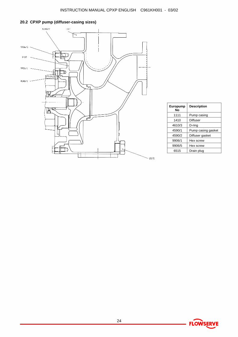
20.2 CPXP pump (diffuser-casing sizes)
EuropumpNo
Description
1111 Pump casing1410 Diffuser
4610/3 D-ring4590/1 Pump casing gasket4590/2 Diffuser gasket9906/1 Hex screw9906/5 Hex screw6515 Drain plug
INSTRUCTION MANUAL CPXP ENGLISH C961KH001 - 03/02
®
25
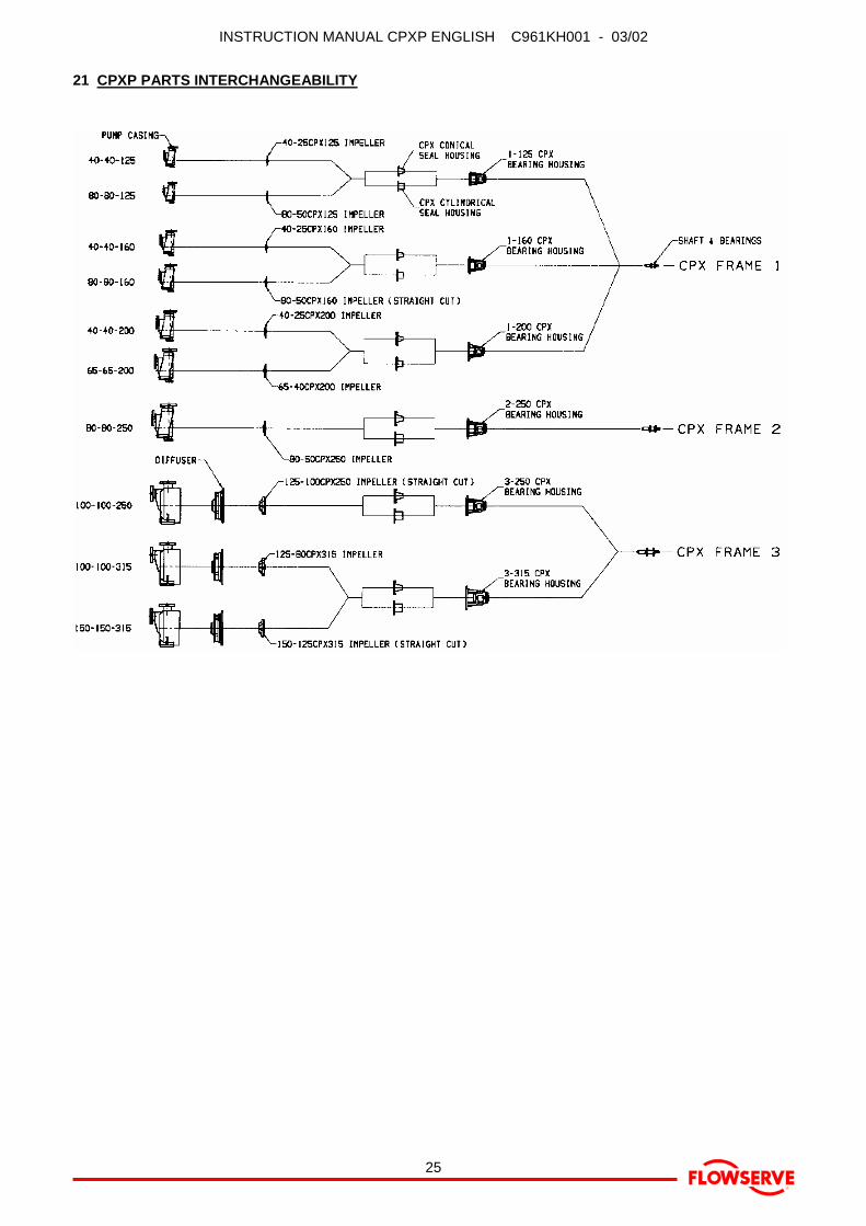
21 CPXP PARTS INTERCHANGEABILITY

INSTRUCTION MANUAL CPXP ENGLISH C961KH001 - 03/02
®
26
Notes:
INSTRUCTION MANUAL CPXP ENGLISH C961KH001 - 03/02
®
27
Notes:
INSTRUCTION MANUAL CPXP ENGLISH C961KH001 - 03/02
®
28
Europe, Middle East & AfricaFlowserve Limited (Pump Division)Harley House, 94 Hare LaneClaygate, Esher, Surrey KT10 0RBUnited Kingdom
Tel +44 (0)1372 463 700Fax +44 (0)1372 460 190
USA and CanadaFlowserve Corporation (Pump Division)Millennium Center, 222 Las Colinas Blvd.15th Floor, Irving, TX 75039-5421, USA
Tel +1 972 443 6500Toll free 800 728 PUMP (7867)Fax +1 972 443 6800
Latin AmericaFlowserve S.A. de C.V.Avenida Paseo de la Reforma #302nd Floor, Colonia Juarez CentroMexico, D.F.Z.C. 06040
Tel +52 5705 5526Fax +52 5705 1125
Asia PacificFlowserve Pte Ltd (Pump Division)200 Pandan Loop, #06-03/04Pantech 21, Singapore 128388
Tel +65 775 3003Fax +65 779 4607
Visit our web site at: www.flowserve.com
Your Flowserve factory contact:
Flowserve Pumps LimitedPO Box 17, NewarkNotts NG24 3ENUnited Kingdom
Telephone (24 hours) +44 (0)1636 494 600Sales & Admin Fax +44 (0)1636 705 991Repair & Service Fax +44 (0)1636 494 833E.mail [email protected]
Your local Flowserve representative:
To find your local Flowserve representative, pleaseuse the Sales Support Locator System found atwww.flowserve.com