Embed Size (px)
Citation preview
APPLICATIONS
Onshore flowback and well testing
Well clean-up operations
Three phase separation and measurement
Extended production tests
Designed to ASME pressure vessel code specifications
Incorporates bypass systems around inlet and all instruments
QA packages on each unit for documentation
RRobust design with clean out man-way and ports available for clean-up
Special designed inlet to hinder large pieces of solids from entering the vessel
Hi / Lo pressure and level shutdowns
Balanced control valves to controllers
LeLevel controls hinged to cutside bridle thus using entire internal vessel area for separation
Level site glasses all mounted to external bridle
Single modulating relief valve, and burst disc secondary
VVane type mist extractor – dual bank
Internal anti wave breaker on all vessels
Vortex breakers on all fluid nozzles at discharge
Strainers are placed upstream of all liquid metering
APPLICATIONS
FEATURES & BENEFITSFEATURES & BENEFITS
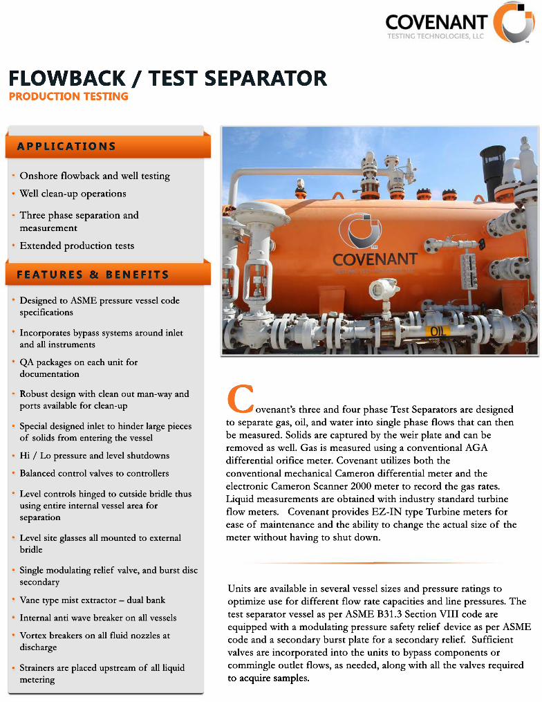
Covenant’s three and four phase Test Separators are designed to separate gas, oil, and water into single phase flows that can then be measured. Solids are captured by the weir plate and can be removed as well. Gas is measured using a conventional AGA differential orifice meter. Covenant utilizes both the coconventional mechanical Cameron differential meter and the electronic Cameron Scanner 2000 meter to record the gas rates. Liquid measurements are obtained with industry standard turbine flow meters. Covenant provides EZ-IN type Turbine meters for ease of maintenance and the ability to change the actual size of the meter without having to shut down.
Units are available in several vessel sizes and pressure ratings to optimize use for different flow rate capacities and line pressures. The test separator vessel as per ASME B31.3 Section VIII code are equipped with a modulating pressure safety relief device as per ASME code and a secondary burst plate for a secondary relief. Sufficient valves are incorporated into the units to bypass components or commingle outlet flows, as needed, along with all the valves required to acquire sampleto acquire samples.
PRODUCTION TESTINGFLOWBACK / TEST SEPARATOR
CTEST.COM 832.500.31071600 Highway 6, Suite 360Sugar Land, TX 77478
Copyright @ 2014 Covenant Testing Technologies, LLC. All rights reserved.
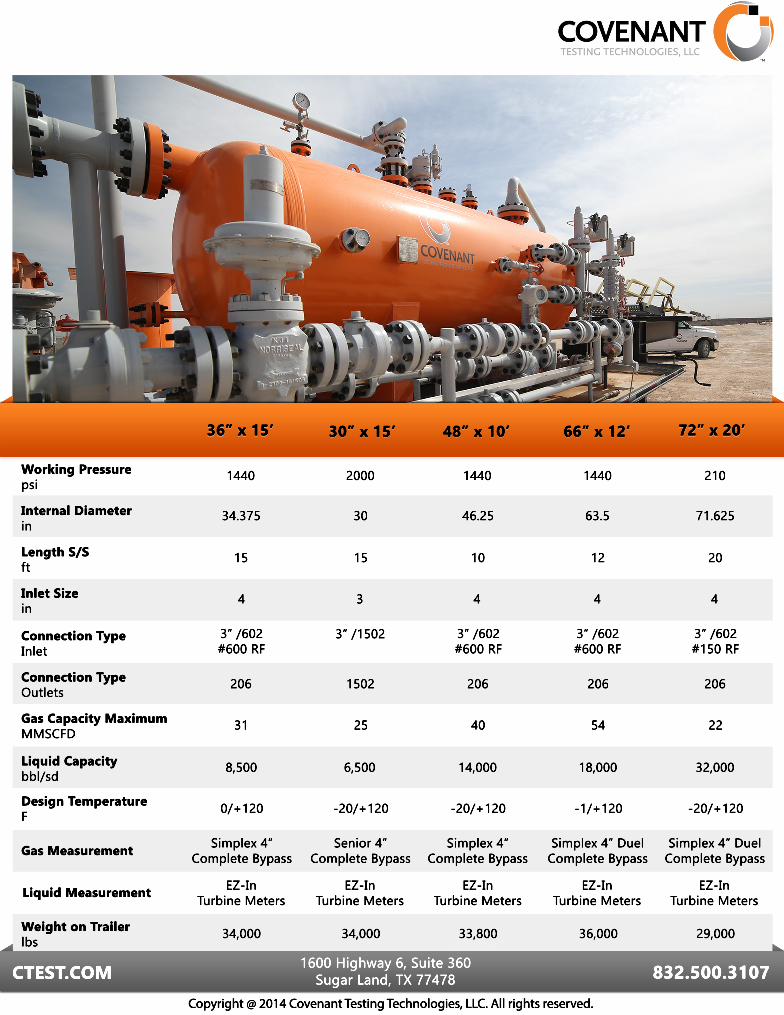
Working Pressure psi
Internal Diameter in
Length S/S ft
Inlet Size in
Connection Type Inlet
Connection Type Outlets
Gas Capacity Maximum MMSCFD
Liquid Capacity bbl/sd
Design TemperatureF
Gas Measurement
Liquid Measurement
36” x 15’36” x 15’
34.375
15
4
3” /602#600 RF
206
31
8,500
0/+120
Simplex 4”Complete Bypass
EZ-In Turbine Meters
34,000
72” x 20’72” x 20’
1440
30
15
3
3” /1502
1502
25
6,500
-20/+120
Senior 4”Complete Bypass
EZ-In Turbine Meters
34,000
2000
46.25
10
4
3” /602#600 RF
206
40
14,000
-20/+120
Simplex 4”Complete Bypass
EZ-In Turbine Meters
33,800
1440
63.5
12
4
3” /602#600 RF
206
54
18,000
-1/+120
Simplex 4” DuelComplete Bypass
EZ-In Turbine Meters
36,000
1440
71.625
20
4
3” /602#150 RF
206
22
32,000
-20/+120
Simplex 4” DuelComplete Bypass
EZ-In Turbine Meters
29,000
210
66” x 12’66” x 12’48” x 10’48” x 10’30” x 15’30” x 15’
Weight on Trailer lbs