Embed Size (px)
Citation preview

Air Flow Through a Regulator Page1 of 9
Flow Through the Regulator
The SCUBA tank regulator arrangement can be idealized with the diagram shown below. This idealization is useful for computing pressures and gas flow rates through the system.
The bold circle represents the regulator you are designing, the circle to the right represents the secondary regulator with the mouth piece the diver breaths from, and the circle to the left represents the tank of compressed air.
We can start the analysis of the flow through the system by looking at the ideal gas law. This law does not work well for all gasses but it is fairly accurate for air.
TRvP = ideal gas law (1)
There are different units for R depending upon the units you are using for pressure, volume, and temperature. We will use the first definition in this presentation.
R = 1545 ft- lbs/lb mole ºR R = 1.986 BTU/lb mole ºR R = 1.986 cal/gm mole ºK Dividing through by the mass of a mole of air results in
MTR
MvP
= (2)
or in a more familiar form
RTPv = (3) The units for this equation are: P = lbf/ft2 = pressure v = ft3/lbm = folume R = ft- lbf/lbm ºR = constant for air 53.3 T = ºR = temperature in degrees Rankine
Tank Reg 1
Reg 2
4,500 psi
500 psig
140 psig
0 psig 200 ft depth 37.5 liters/min

Air Flow Through a Regulator Page2 of 9
Note that the volume v is per pound mass. If we wanted to measure a volume other than 1 lbm we could multiply through by m the mass of the material in which we are interested.
mRTmPv = (4)
let
mvV = (5)
our equation becomes
mRTPV = (6)
You should be able to check this equation to see if it is dimensionally correct.
Pressure and Depth
The pressure exerted on the diver increases as the diver descends in the water column. We need to compute this pressure because the diver is breathing at that depth and we must compute the absolute pressure at that depth. Sea water weight approximately 64 lbs per cubic foot. The pressure at 200 feet of depth is:
P = 200 ft * 64 lbf/ft3 = 12,800 lbf / ft2 gauge (7)
We can convert this from pounds per square foot to the more familiar pounds per square
inch (psi) by dividing by 144.
P = 12,800 / 144 = 88.9 psig (8) This is gauge pressure because we have not accounted for atmospheric pressure pressing
down on the surface of the water.
Pabs = psig + 1 atm = 88.9 + 14.7 = 103.6 psiabs (9) Or restating in psf
Pabs = 103.6 x 144 = 14,918.4 lbf / ft2 (10)
Volumetric Flow Rate at the Diver
One of the cases we must investigate is for a single diver using 37.5 liters of air per minute at a depth of 200 feet. Most of our units are imperial so we will convert the liters per minute to cubic feet per second.
1 ft3 = 28.32 liters (11)
V = 37.5 / 28.32 = 1.32 ft3 (12)

Air Flow Through a Regulator Page3 of 9
And the flow rate is
sec/022.0min/32.1 33 ftftV ==& (13)
Mass Flow Rate Through the System We will assume that the temperature of the air the diver is breathing is approximately the
temperature of the water. This temperature can range from about 28 ºF to about 90 ºF. The sea does not usually warmer than 90 ºF and water below 28 ºF is called ice. For the purpose of this paper, we will assume a temperature of 60 ºF. You might want to explore other temperatures to see what effect they have on your regulator.
The temperature needed for the ideal gas law is expressed in degrees Rankine. This temperature scale is measured from absolute zero.
T = 60 ºF + 460 = 520 ºR (14)
From the ideal gas law we know
PV = mRT (15)
m = PV/RT (16)
Or stating as a mass flow rate
RTVP
m&
& = (17)
sec0118.0
3.53520022.0918,14 lbmm =
××=& (18)
Volumetric Flow Rate into Second Stage Regulator
This is the mass flow rate through the entire system. We can now use the ideal gas law to
find the volumetric flow rate through the entire system. The pressure between the first and second stage regulators is 140 psi gauge. We can convert this to absolute pressure by adding the pressure due to the depth (200 feet) and the pressure of the atmosphere on the surface of the water.
Pabs = 140 + 88.9 + 14.7 = 243.6 psiabs = 35,078 psfabs (19)
Assume that T = 60 ºF or 520 ºR and our equation becomes
sec0093.0
078,355203.530118.0 3ft
PRTm
V =××== && (20)
Air Flow Through a Regulator Page4 of 9
Volumetric Flow Rate into First Stage Regulator The volumetric flow rate between the tank and the first stage regulator can be computed
using a similar technique. Assume that the tank contains 3000 psi and it was filled on the surface. The pressure becomes
Pgauge = 3000 psi (21)
Pabs = 3000 + 14.7 = 3014.7 psi = 434,117 psf (22)
Our volumetric flow rate becomes
sec00075.0
117,4345203.530118.0 3ft
PRTm
V =××
==&& (23)
Density of Air into First Stage Regulator
We can also compute the density of the air at the tank.
Pv = RT (24)
v = RT/P (25)
RTP
v== 1ρ (26)
366.15
5203.53117,434
ftlbm
=×
=ρ (27)
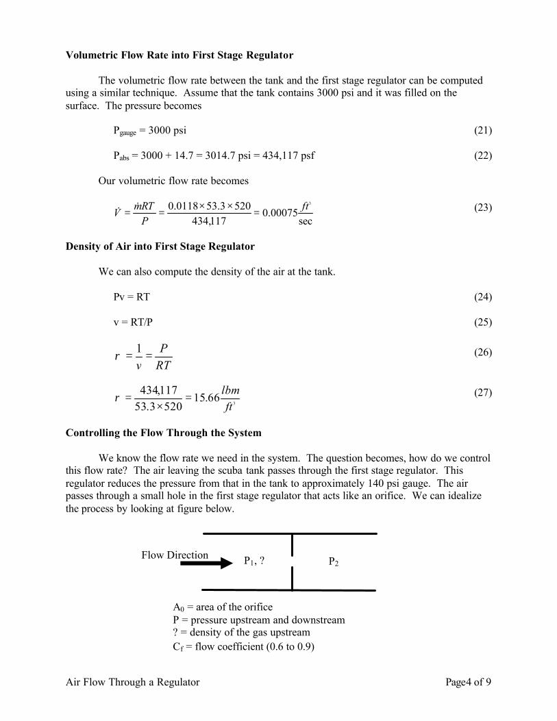
Controlling the Flow Through the System We know the flow rate we need in the system. The question becomes, how do we control this flow rate? The air leaving the scuba tank passes through the first stage regulator. This regulator reduces the pressure from that in the tank to approximately 140 psi gauge. The air passes through a small hole in the first stage regulator that acts like an orifice. We can idealize the process by looking at figure below.
Flow Direction P1, ? P2
A0 = area of the orifice P = pressure upstream and downstream ? = density of the gas upstream Cf = flow coefficient (0.6 to 0.9)

Air Flow Through a Regulator Page5 of 9
We can compute the mass flow rate with the following equation.
21 ppp −=∆ (29)
ρρ
pACm
f
∆=
20
& (30)
Rewriting this equation to solve for A0 the area of the orifice we get.
ρρ PC
mA
f
∆=
20
& (31)
or
22
000014.0000000965.0
66.15)1403000(*2.32*144*2
6.066.15
0118.0 inftA ==−
×=
(32)
The area required may be different for different temperatures, pressures and flow rates. You must investigate all of these to determine the maximum area. The 32.2 is the acceleration due to gravity. We need this because we are measuring mass in pounds. Temperature Change across the Orifice We have assumed that the temperature drop across the orifice or through the regulator is zero. Is this a valid assumption? We will examine this by assuming that air obeys the ideal gas law. If there is a temperature change accompanying a pressure change, it could be expressed mathematically as
∂∂
≈∆∆
PT
PT (33)
Looking at an energy balance on both sides of the orifice that
22
2
2
2
2
1
1
Vhw
Vhq ++=++ (34)
where q = the heat transfer between the regulator and the surrounding water. h = the enthalpy of the air at a specific location V = the velocity of the air W = work done by the air as it moves through the orifice

Air Flow Through a Regulator Page6 of 9
The process takes place very quickly so we assume there is no heat is transferred into or out of the system. This being the case,
0=q . (35) Nothing but the air is being moved so there is no work going on so
0=w . (36)
Our equation becomes
22
2
2
2
2
1
1
Vh
Vh +=+ (37)
If the velocities on both sides of the orifice are about the same then we can reduce the equation further as
21 hh = (38)
For an ideal gas
RTuPvuh +=+= (39)
where u is the energy of the gas. From thermodynamics we know that the specific heat as a constant volume for an ideal
gas can be written as
dTdu
tu
Cv
v =
∂∂
= (40)
So
dTCdu v= (41)
Cv is a constant so it appears that u is a function of T only. We now look at the enthalpy equation and we see that h must also be a function of T only.
RTuh += (42)
Now we look at the Joule-Thomson expansion equation. It is
Functions of T

Air Flow Through a Regulator Page7 of 9
hJT P
T
∂∂
=µ (43)
Using the chain rule we can rewrite this as
p
P
T
h CPh
ThPh
PT
∂∂
−=
∂∂
∂∂
−=
∂∂
(44)
But we have established for an ideal gas that h is a function of T only so
0=
∂∂
TPh
(45)
Therefore, for an ideal gas
0=
∂∂
hPT
(46)
This tells us the temperature is the same on both sides of the orifice. Changing the Orifice
If we change the problem a little, we can get some cooling from the system. Note that the orifice in the previous problem was very short in the direction of the gas flow and this prevented much heat from being transferred at the orifice. If we change the picture a little, this may not be the case. Consider
Instead of the orifice being a small hole in a plate, it is now a small diameter tube. We can see from the picture that the velocities of the gas may not be the same in both the upstream and in the orifice tube. The velocity changes because to the change in area of the tube and the drop in pressure as the gas moves through the orifice tube.
Previously we derived the equation.
Flow Direction V1 V2

Air Flow Through a Regulator Page8 of 9
22
2
2
2
2
1
1
VhwVhq ++=++
(47)
We assume there is no heat being transferred in or out and there is no work being done so our equation becomes.
22
2
2
2
2
1
1
Vh
Vh +=+ (48)
or
22
2
1
2
2
21
VVhh −=− (49)
If we assume that the specific heat is a constant then we can use the equation below to
compute the temperature. We can use the equation because the enthalpy for an ideal gas is only dependent upon the temperature and is independent of the pressure.
)(22 21
2
1
2
2
21 TTCVV
hh p −=−=− (50)
or
( )2
1
2
212 21
VVC
TTP
−−= (51)
We can have cooling in the small orifice tube due to the increase in velocity of the gas
but the temperature will rise as soon as the gas leaves the small tube and slows down again.
Assignment
Fill in the missing fields in the table below. Assume a water temperature of 60 ºF and an orifice coefficient of 0.6 .
Depth (ft seawater)
Pressure in Tank (psi)
Diver Breathing rate
(liters / minute)
Mass Flow Rate (lbs / minute)
Density of air in the Tank (lbm / ft3)
Area of orifice (in2)
130 4500 62.5 130 3000 62.5 130 500 62.5 200 4500 37.5 200 3000 37.5 200 500 37.5

Air Flow Through a Regulator Page9 of 9
What is the maximum orifice size (area) and what are the operating conditions at this size.