Embed Size (px)
Citation preview

AASHTOWare BrD/BrR 6.8
Floor System Tutorial
FS3 - Floorbeam Stringer Floor System Example
FS3 - Floorbeam Stringer System Example
Last Modified: 8/30/2016 1
Topics Covered
Superstructure composed of floorbeams and stringers
System Superstructure Definition
Rolled beam stringers
Plate girder floorbeams, linearly varying web
Using wizards to create member alternatives for stringer and floorbeam members
This example demonstrates entering a Floorbeam-Stringer superstructure in BrR using the System superstructure
definition approach. It is assumed that the user of this example is an advanced user who is familiar with the basics
of BrR. As such, the details of creating bridge materials, beam shapes, etc., are not presented in great detail in this
example.
If you have already completed example problem “FS2-Floorbeam Stringer Line Example”, you can open the bridge
you created in that example and jump to Page FS4-5 to start this example. If you have not completed “FS2-
Floorbeam Stringer Line Example”, continue with this page.
FS3 - Floorbeam Stringer System Example
Last Modified: 8/30/2016 2
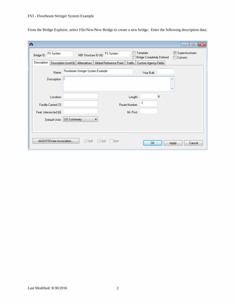
From the Bridge Explorer, select File/New/New Bridge to create a new bridge. Enter the following description data:
FS3 - Floorbeam Stringer System Example
Last Modified: 8/30/2016 3
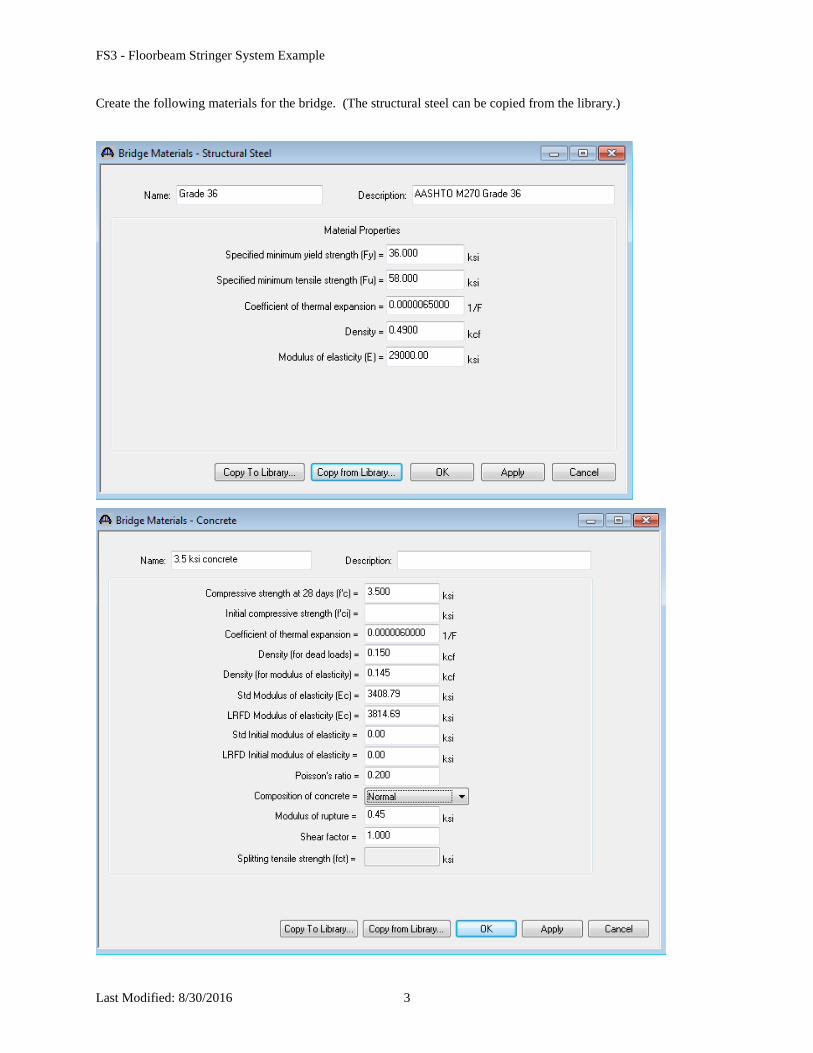
Create the following materials for the bridge. (The structural steel can be copied from the library.)
FS3 - Floorbeam Stringer System Example
Last Modified: 8/30/2016 4
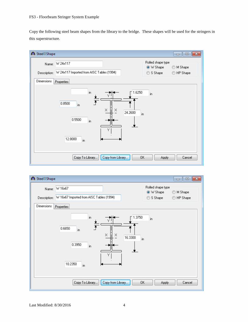
Copy the following steel beam shapes from the library to the bridge. These shapes will be used for the stringers in
this superstructure.
FS3 - Floorbeam Stringer System Example
Last Modified: 8/30/2016 5
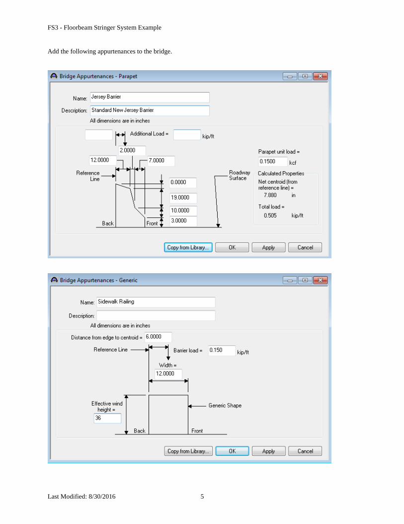
Add the following appurtenances to the bridge.
FS3 - Floorbeam Stringer System Example
Last Modified: 8/30/2016 6
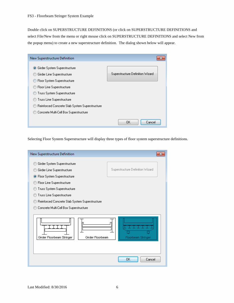
Double click on SUPERSTRUCTURE DEFINITIONS (or click on SUPERSTRUCTURE DEFINITIONS and
select File/New from the menu or right mouse click on SUPERSTRUCTURE DEFINITIONS and select New from
the popup menu) to create a new superstructure definition. The dialog shown below will appear.
Selecting Floor System Superstructure will display three types of floor system superstructure definitions.
FS3 - Floorbeam Stringer System Example
Last Modified: 8/30/2016 7
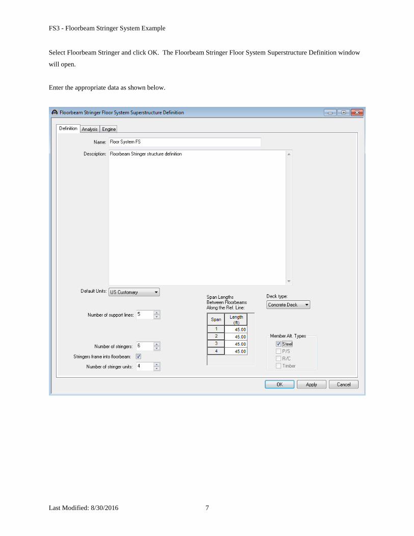
Select Floorbeam Stringer and click OK. The Floorbeam Stringer Floor System Superstructure Definition window
will open.
Enter the appropriate data as shown below.
FS3 - Floorbeam Stringer System Example
Last Modified: 8/30/2016 8
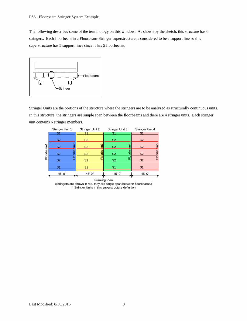
The following describes some of the terminology on this window. As shown by the sketch, this structure has 6
stringers. Each floorbeam in a Floorbeam-Stringer superstructure is considered to be a support line so this
superstructure has 5 support lines since it has 5 floorbeams.
Floorbeam
Stringer
Stringer Units are the portions of the structure where the stringers are to be analyzed as structurally continuous units.
In this structure, the stringers are simple span between the floorbeams and there are 4 stringer units. Each stringer
unit contains 6 stringer members.
Framing Plan
(Stringers are shown in red, they are single span between floorbeams.)
4 Stringer Units in this superstructure definition
Stringer Unit 1 Stringer Unit 2
Flo
orb
ea
m1
Flo
orb
ea
m4
Flo
orb
ea
m2
Flo
orb
ea
m3
Flo
orb
ea
m5
S1
S1
S2
S2
S2
S2
S1
S1
S2
S2
S2
S2
S1
S1
S2
S2
S2
S2
S1
S1
S2
S2
S2
S2
Stringer Unit 3 Stringer Unit 4
45'-0" 45'-0"45'-0"45'-0"
FS3 - Floorbeam Stringer System Example
Last Modified: 8/30/2016 9
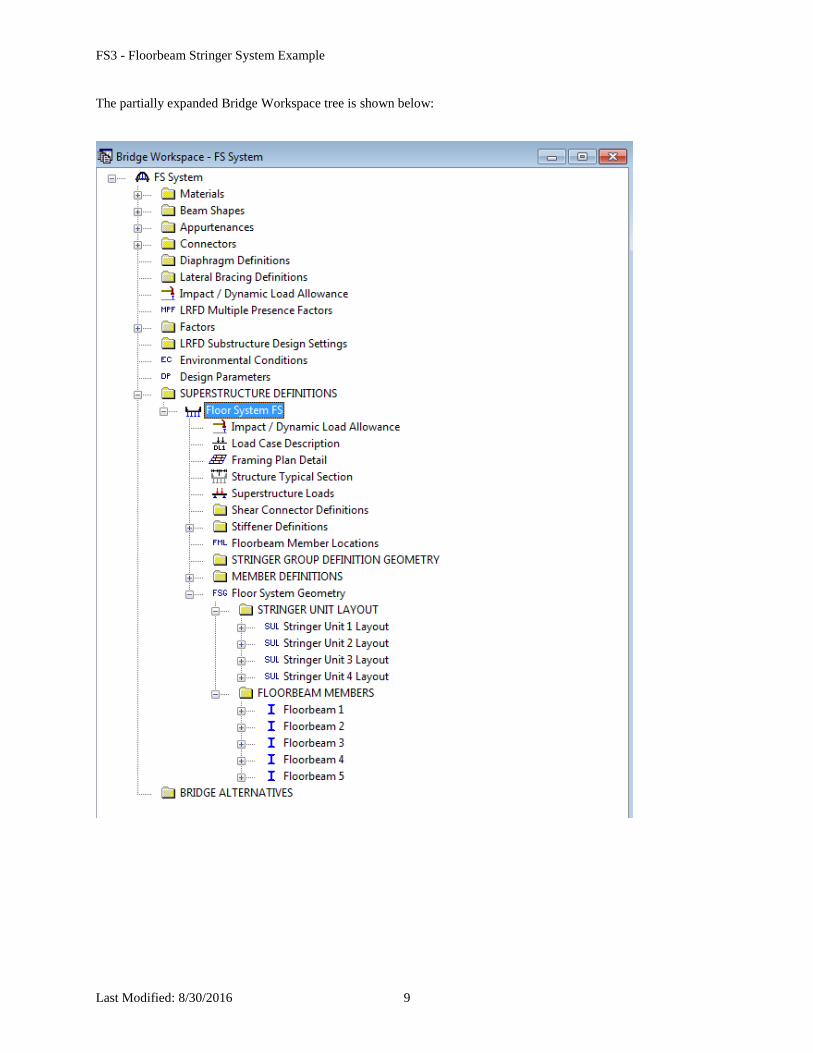
The partially expanded Bridge Workspace tree is shown below:
FS3 - Floorbeam Stringer System Example
Last Modified: 8/30/2016 10
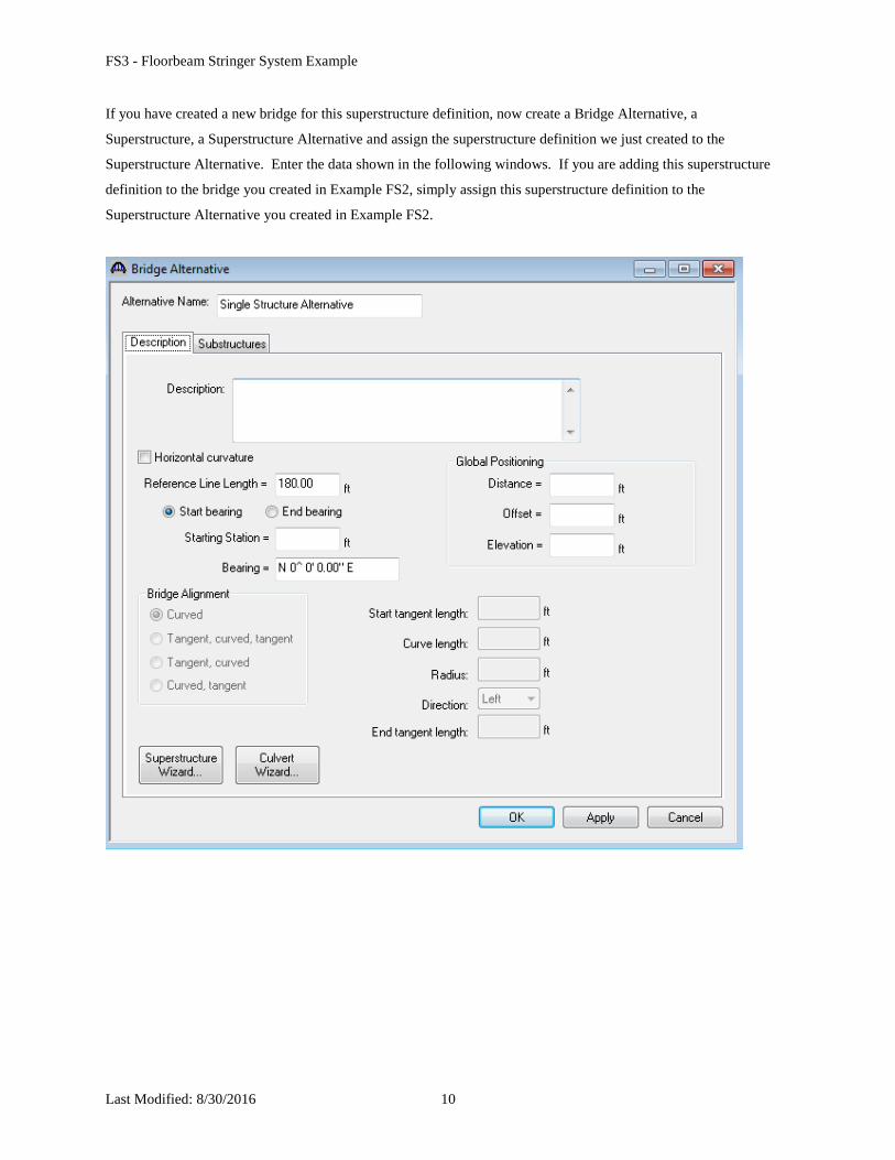
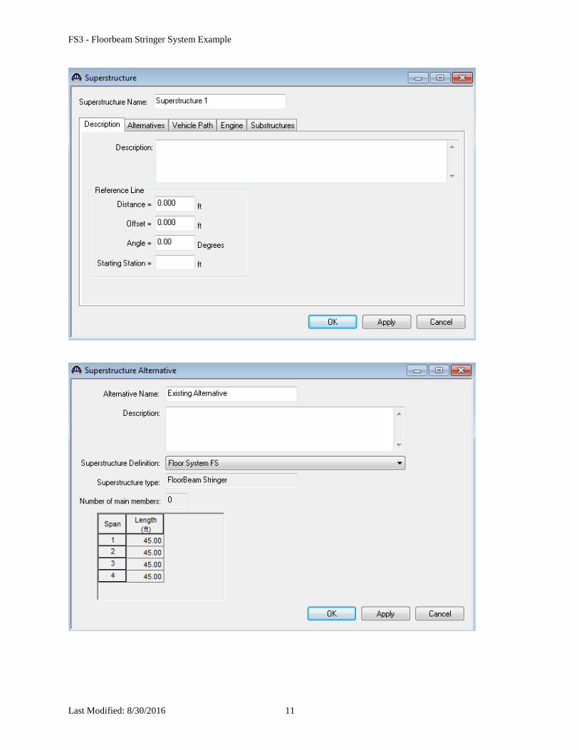
If you have created a new bridge for this superstructure definition, now create a Bridge Alternative, a
Superstructure, a Superstructure Alternative and assign the superstructure definition we just created to the
Superstructure Alternative. Enter the data shown in the following windows. If you are adding this superstructure
definition to the bridge you created in Example FS2, simply assign this superstructure definition to the
Superstructure Alternative you created in Example FS2.
FS3 - Floorbeam Stringer System Example
Last Modified: 8/30/2016 11
FS3 - Floorbeam Stringer System Example
Last Modified: 8/30/2016 12
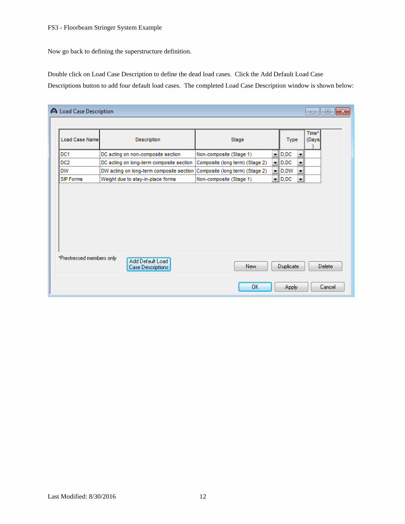
Now go back to defining the superstructure definition.
Double click on Load Case Description to define the dead load cases. Click the Add Default Load Case
Descriptions button to add four default load cases. The completed Load Case Description window is shown below:
FS3 - Floorbeam Stringer System Example
Last Modified: 8/30/2016 13
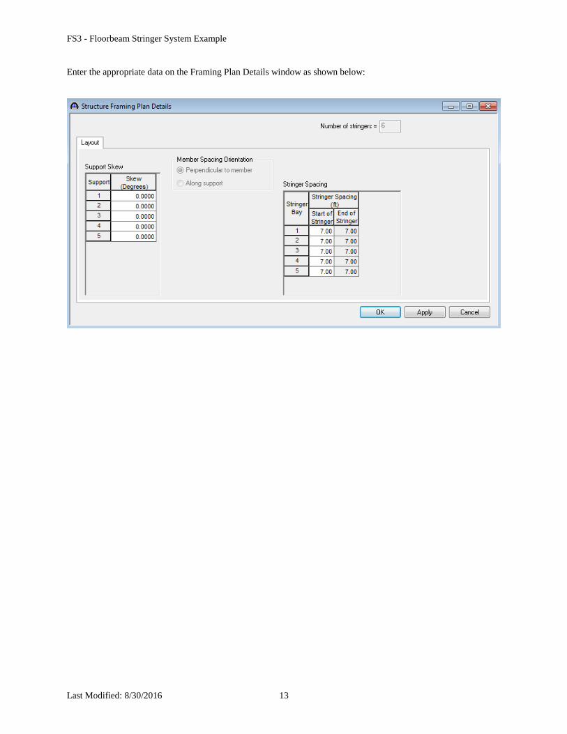
Enter the appropriate data on the Framing Plan Details window as shown below:
FS3 - Floorbeam Stringer System Example
Last Modified: 8/30/2016 14
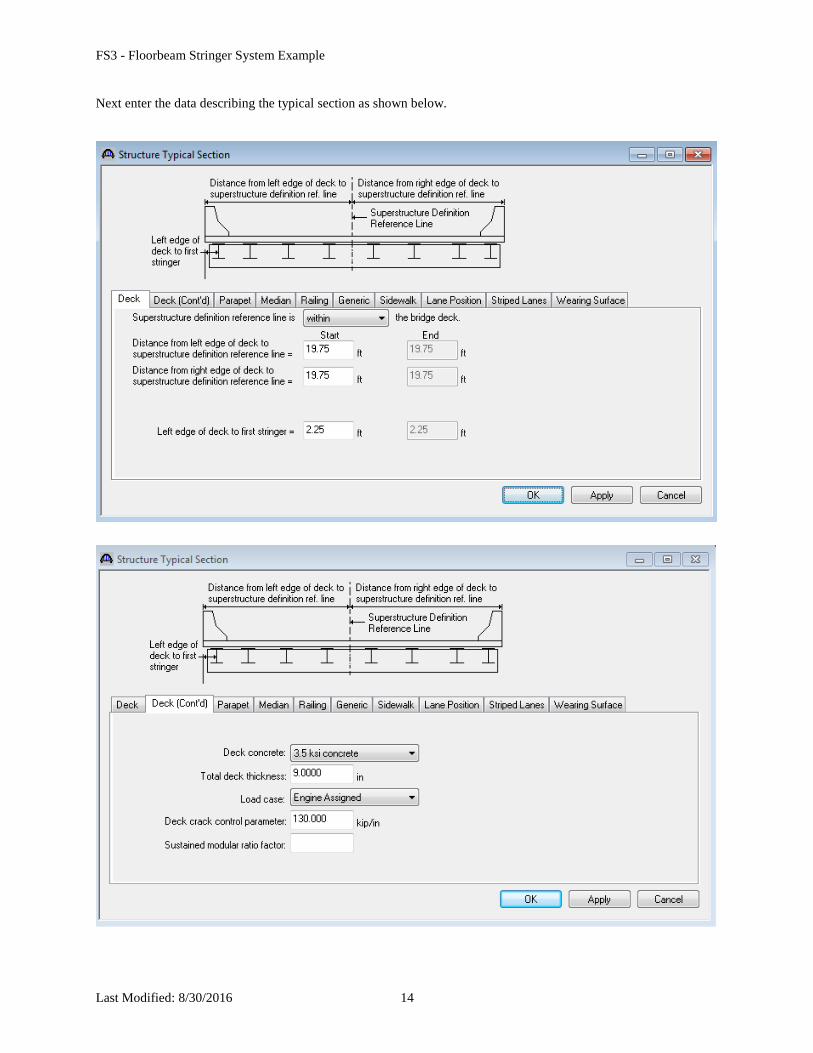
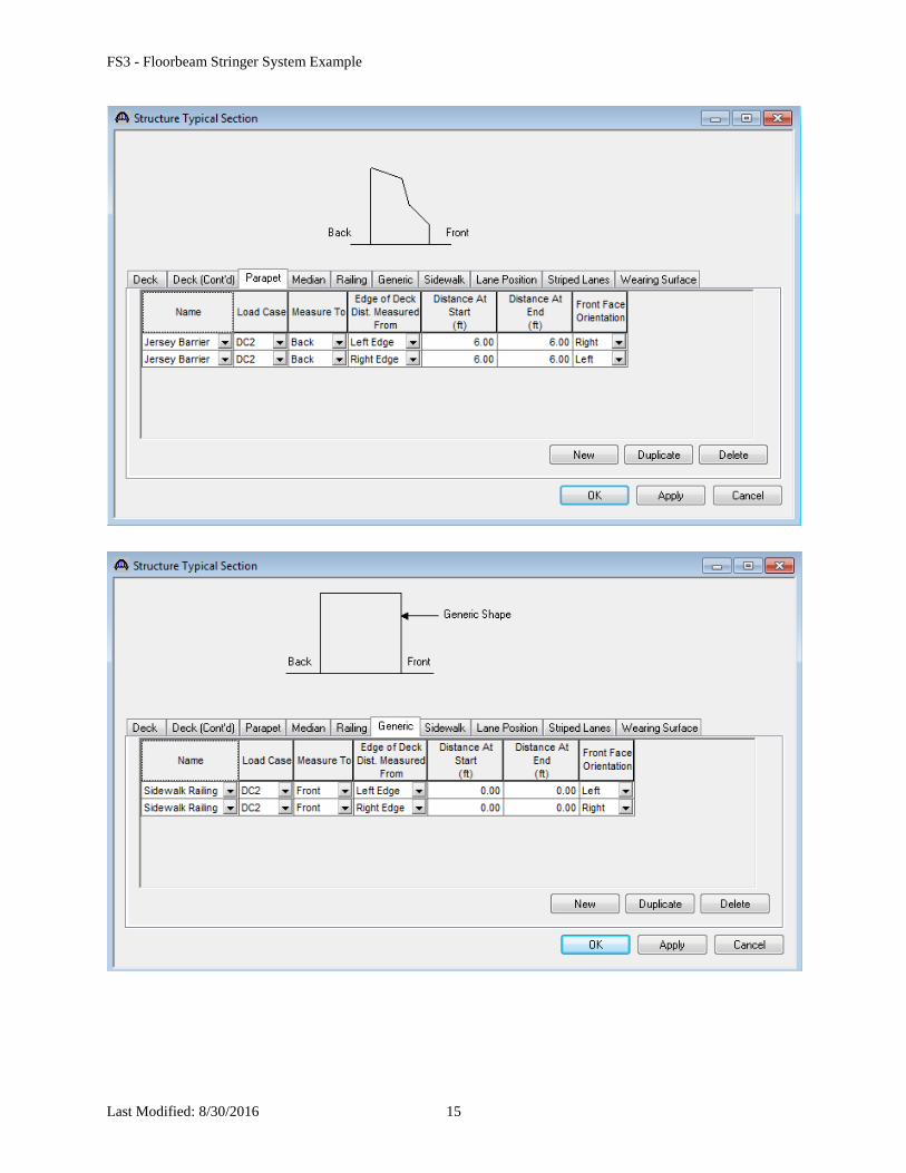
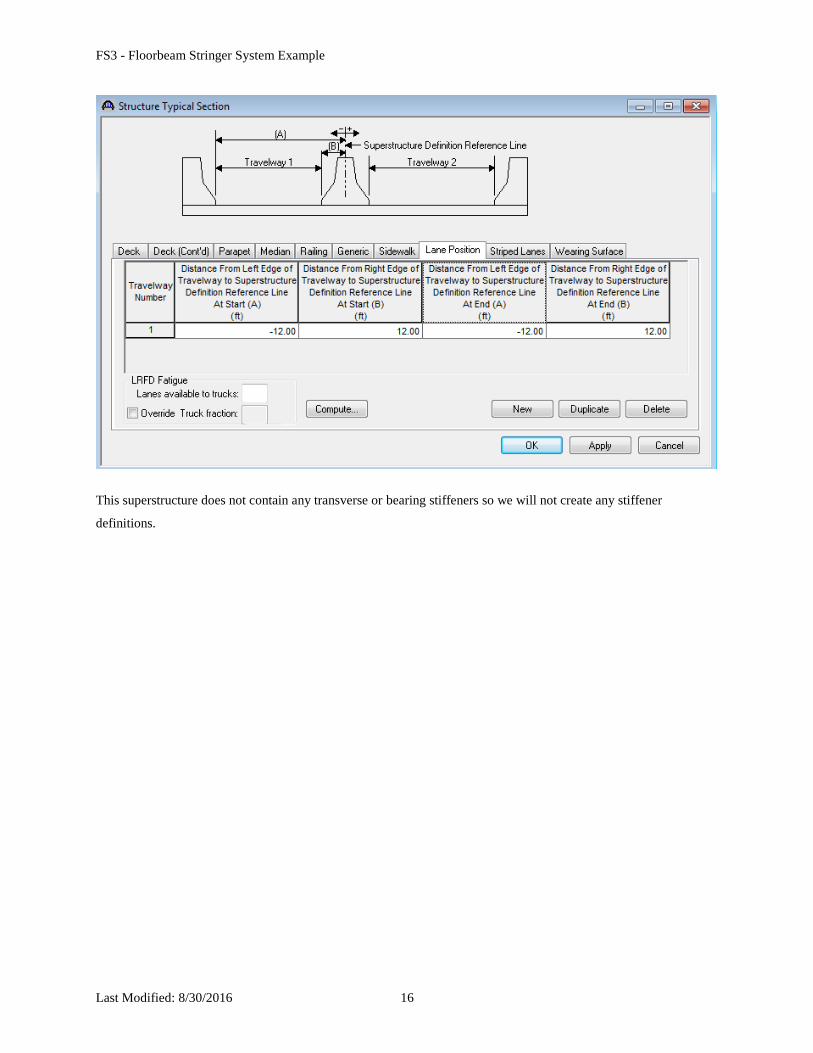
Next enter the data describing the typical section as shown below.
FS3 - Floorbeam Stringer System Example
Last Modified: 8/30/2016 15
FS3 - Floorbeam Stringer System Example
Last Modified: 8/30/2016 16
This superstructure does not contain any transverse or bearing stiffeners so we will not create any stiffener
definitions.
FS3 - Floorbeam Stringer System Example
Last Modified: 8/30/2016 17
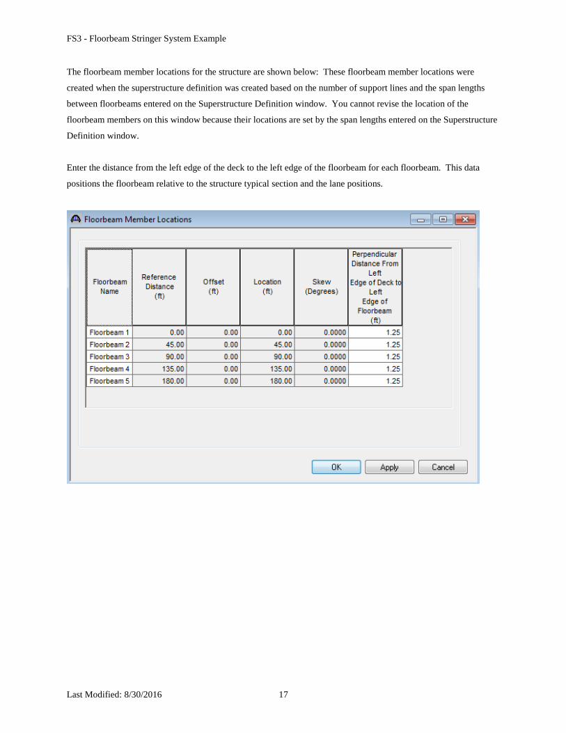
The floorbeam member locations for the structure are shown below: These floorbeam member locations were
created when the superstructure definition was created based on the number of support lines and the span lengths
between floorbeams entered on the Superstructure Definition window. You cannot revise the location of the
floorbeam members on this window because their locations are set by the span lengths entered on the Superstructure
Definition window.
Enter the distance from the left edge of the deck to the left edge of the floorbeam for each floorbeam. This data
positions the floorbeam relative to the structure typical section and the lane positions.
FS3 - Floorbeam Stringer System Example
Last Modified: 8/30/2016 18
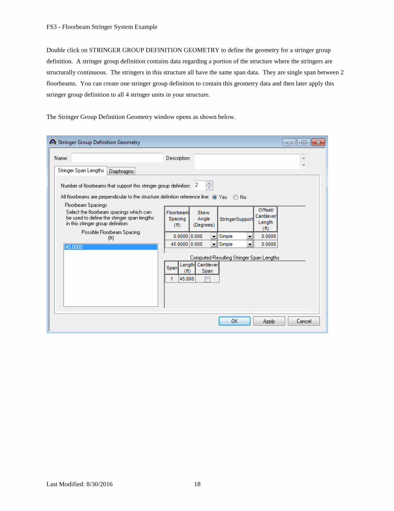
Double click on STRINGER GROUP DEFINITION GEOMETRY to define the geometry for a stringer group
definition. A stringer group definition contains data regarding a portion of the structure where the stringers are
structurally continuous. The stringers in this structure all have the same span data. They are single span between 2
floorbeams. You can create one stringer group definition to contain this geometry data and then later apply this
stringer group definition to all 4 stringer units in your structure.
The Stringer Group Definition Geometry window opens as shown below.
FS3 - Floorbeam Stringer System Example
Last Modified: 8/30/2016 19
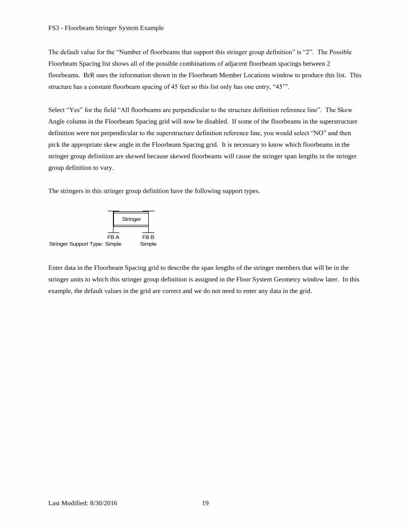
The default value for the “Number of floorbeams that support this stringer group definition” is “2”. The Possible
Floorbeam Spacing list shows all of the possible combinations of adjacent floorbeam spacings between 2
floorbeams. BrR uses the information shown in the Floorbeam Member Locations window to produce this list. This
structure has a constant floorbeam spacing of 45 feet so this list only has one entry, “45’”.
Select “Yes” for the field “All floorbeams are perpendicular to the structure definition reference line”. The Skew
Angle column in the Floorbeam Spacing grid will now be disabled. If some of the floorbeams in the superstructure
definition were not perpendicular to the superstructure definition reference line, you would select “NO” and then
pick the appropriate skew angle in the Floorbeam Spacing grid. It is necessary to know which floorbeams in the
stringer group definition are skewed because skewed floorbeams will cause the stringer span lengths in the stringer
group definition to vary.
The stringers in this stringer group definition have the following support types.
FB BFB A
Simple Simple
Stringer
Stringer Support Type:
Enter data in the Floorbeam Spacing grid to describe the span lengths of the stringer members that will be in the
stringer units to which this stringer group definition is assigned in the Floor System Geometry window later. In this
example, the default values in the grid are correct and we do not need to enter any data in the grid.
FS3 - Floorbeam Stringer System Example
Last Modified: 8/30/2016 20
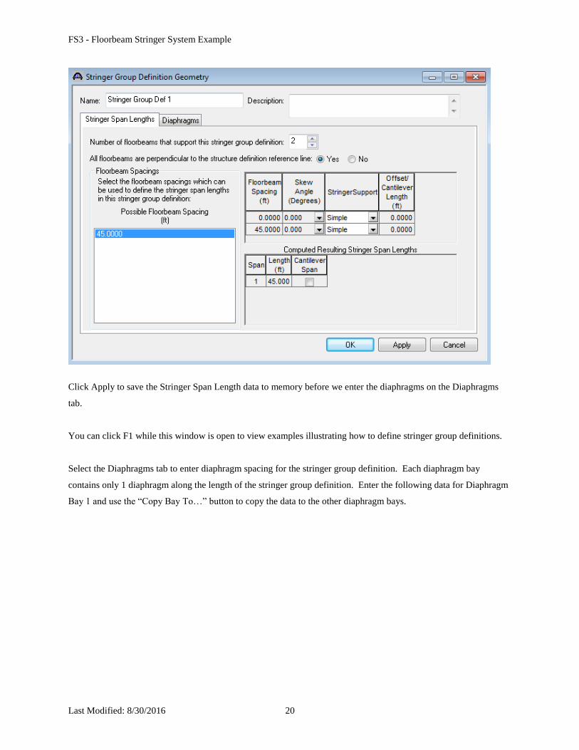
Click Apply to save the Stringer Span Length data to memory before we enter the diaphragms on the Diaphragms
tab.
You can click F1 while this window is open to view examples illustrating how to define stringer group definitions.
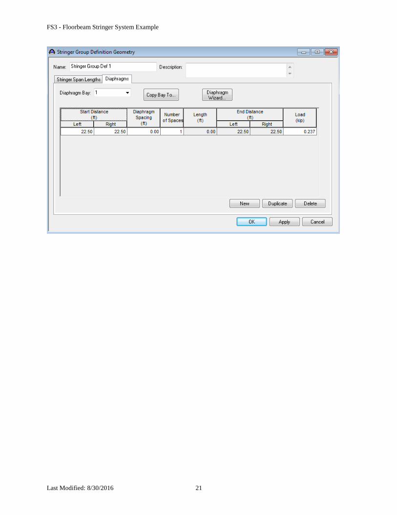
Select the Diaphragms tab to enter diaphragm spacing for the stringer group definition. Each diaphragm bay
contains only 1 diaphragm along the length of the stringer group definition. Enter the following data for Diaphragm
Bay 1 and use the “Copy Bay To…” button to copy the data to the other diaphragm bays.
FS3 - Floorbeam Stringer System Example
Last Modified: 8/30/2016 21
FS3 - Floorbeam Stringer System Example
Last Modified: 8/30/2016 22
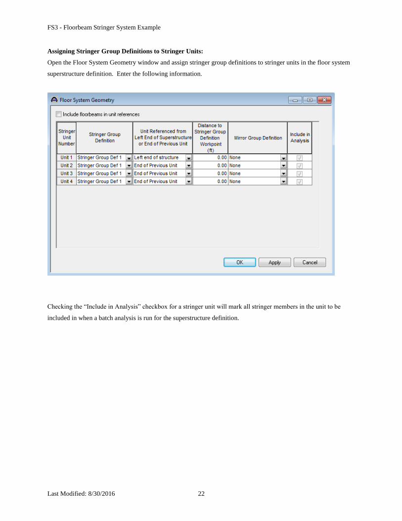
Assigning Stringer Group Definitions to Stringer Units:
Open the Floor System Geometry window and assign stringer group definitions to stringer units in the floor system
superstructure definition. Enter the following information.
Checking the “Include in Analysis” checkbox for a stringer unit will mark all stringer members in the unit to be
included in when a batch analysis is run for the superstructure definition.
FS3 - Floorbeam Stringer System Example
Last Modified: 8/30/2016 23
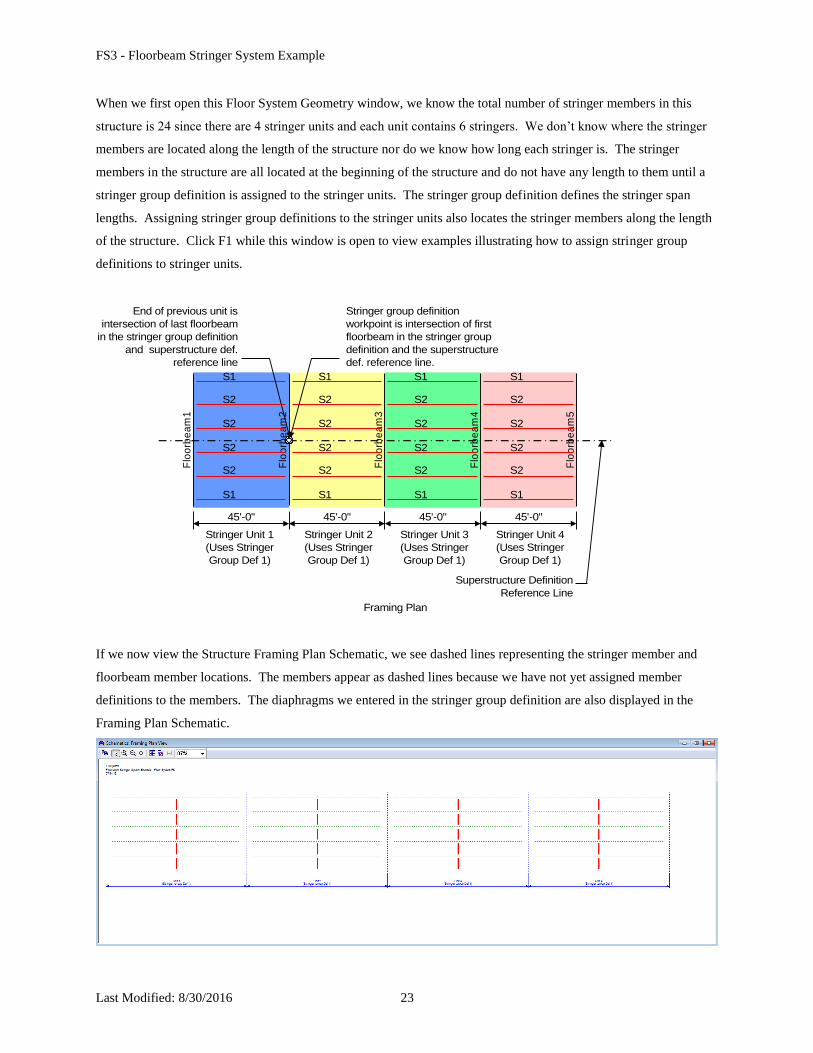
When we first open this Floor System Geometry window, we know the total number of stringer members in this
structure is 24 since there are 4 stringer units and each unit contains 6 stringers. We don’t know where the stringer
members are located along the length of the structure nor do we know how long each stringer is. The stringer
members in the structure are all located at the beginning of the structure and do not have any length to them until a
stringer group definition is assigned to the stringer units. The stringer group definition defines the stringer span
lengths. Assigning stringer group definitions to the stringer units also locates the stringer members along the length
of the structure. Click F1 while this window is open to view examples illustrating how to assign stringer group
definitions to stringer units.
Framing Plan
Stringer Unit 1
(Uses Stringer
Group Def 1)
Flo
orb
ea
m1
Flo
orb
ea
m4
Flo
orb
ea
m2
Flo
orb
ea
m3
Flo
orb
ea
m5
S1
S1
S2
S2
S2
S2
S1
S1
S2
S2
S2
S2
S1
S1
S2
S2
S2
S2
S1
S1
S2
S2
S2
S2
45'-0" 45'-0"45'-0"45'-0"
Superstructure Definition
Reference Line
Stringer Unit 2
(Uses Stringer
Group Def 1)
Stringer Unit 3
(Uses Stringer
Group Def 1)
Stringer Unit 4
(Uses Stringer
Group Def 1)
End of previous unit is
intersection of last floorbeam
in the stringer group definition
and superstructure def.
reference line
Stringer group definition
workpoint is intersection of first
floorbeam in the stringer group
definition and the superstructure
def. reference line.
If we now view the Structure Framing Plan Schematic, we see dashed lines representing the stringer member and
floorbeam member locations. The members appear as dashed lines because we have not yet assigned member
definitions to the members. The diaphragms we entered in the stringer group definition are also displayed in the
Framing Plan Schematic.
FS3 - Floorbeam Stringer System Example
Last Modified: 8/30/2016 24
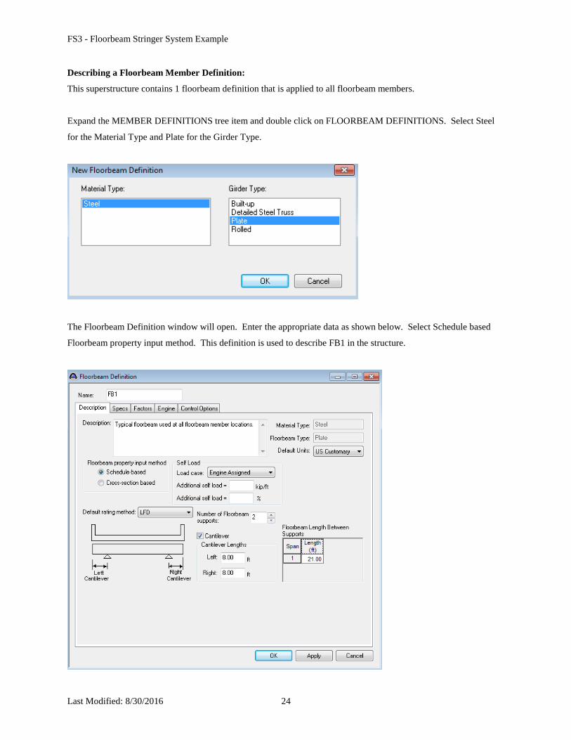
Describing a Floorbeam Member Definition:
This superstructure contains 1 floorbeam definition that is applied to all floorbeam members.
Expand the MEMBER DEFINITIONS tree item and double click on FLOORBEAM DEFINITIONS. Select Steel
for the Material Type and Plate for the Girder Type.
The Floorbeam Definition window will open. Enter the appropriate data as shown below. Select Schedule based
Floorbeam property input method. This definition is used to describe FB1 in the structure.
FS3 - Floorbeam Stringer System Example
Last Modified: 8/30/2016 25
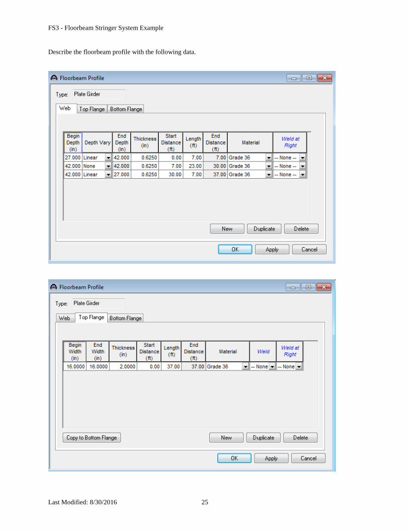
Describe the floorbeam profile with the following data.
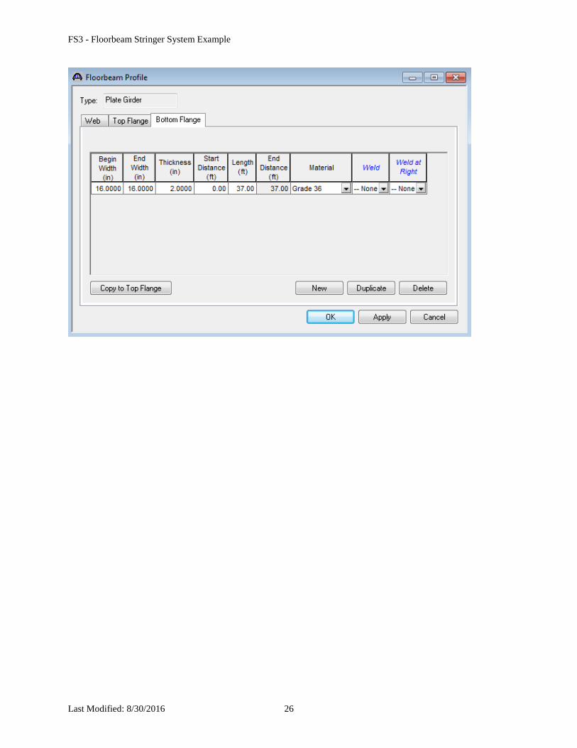
FS3 - Floorbeam Stringer System Example
Last Modified: 8/30/2016 26
FS3 - Floorbeam Stringer System Example
Last Modified: 8/30/2016 27
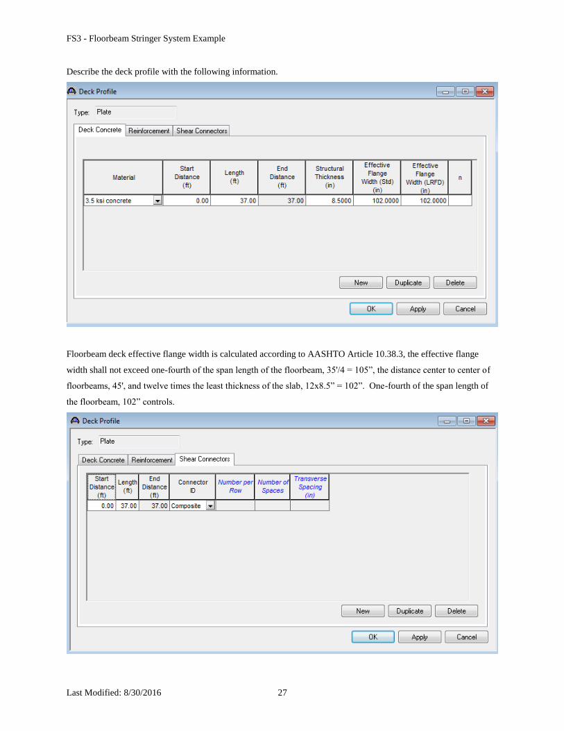
Describe the deck profile with the following information.
Floorbeam deck effective flange width is calculated according to AASHTO Article 10.38.3, the effective flange
width shall not exceed one-fourth of the span length of the floorbeam, 35'/4 = 105”, the distance center to center of
floorbeams, 45', and twelve times the least thickness of the slab, 12x8.5” = 102”. One-fourth of the span length of
the floorbeam, 102” controls.
FS3 - Floorbeam Stringer System Example
Last Modified: 8/30/2016 28
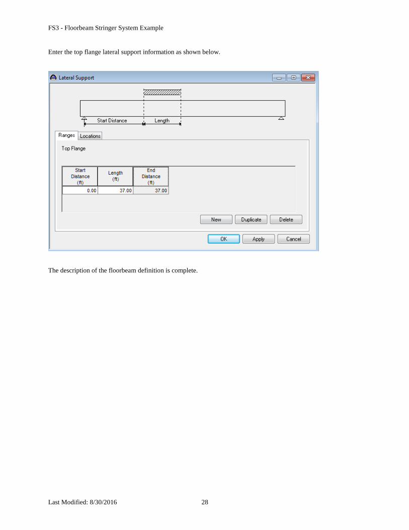
Enter the top flange lateral support information as shown below.
The description of the floorbeam definition is complete.
FS3 - Floorbeam Stringer System Example
Last Modified: 8/30/2016 29
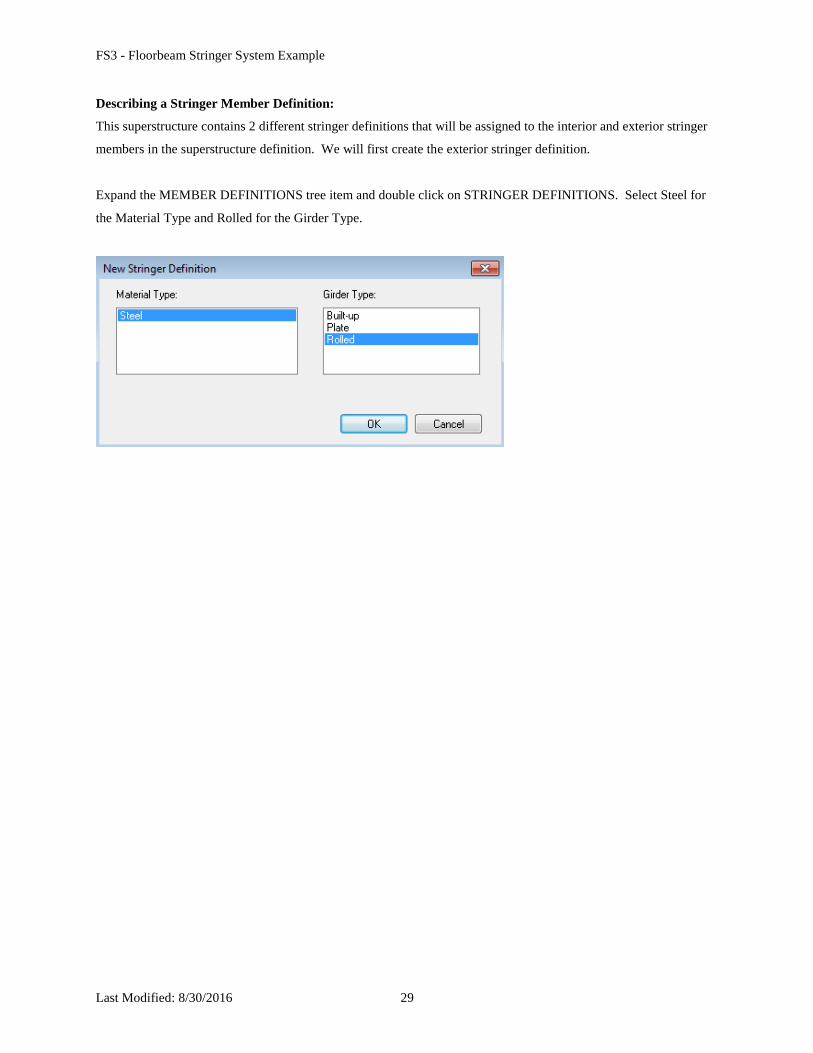
Describing a Stringer Member Definition:
This superstructure contains 2 different stringer definitions that will be assigned to the interior and exterior stringer
members in the superstructure definition. We will first create the exterior stringer definition.
Expand the MEMBER DEFINITIONS tree item and double click on STRINGER DEFINITIONS. Select Steel for
the Material Type and Rolled for the Girder Type.
FS3 - Floorbeam Stringer System Example
Last Modified: 8/30/2016 30
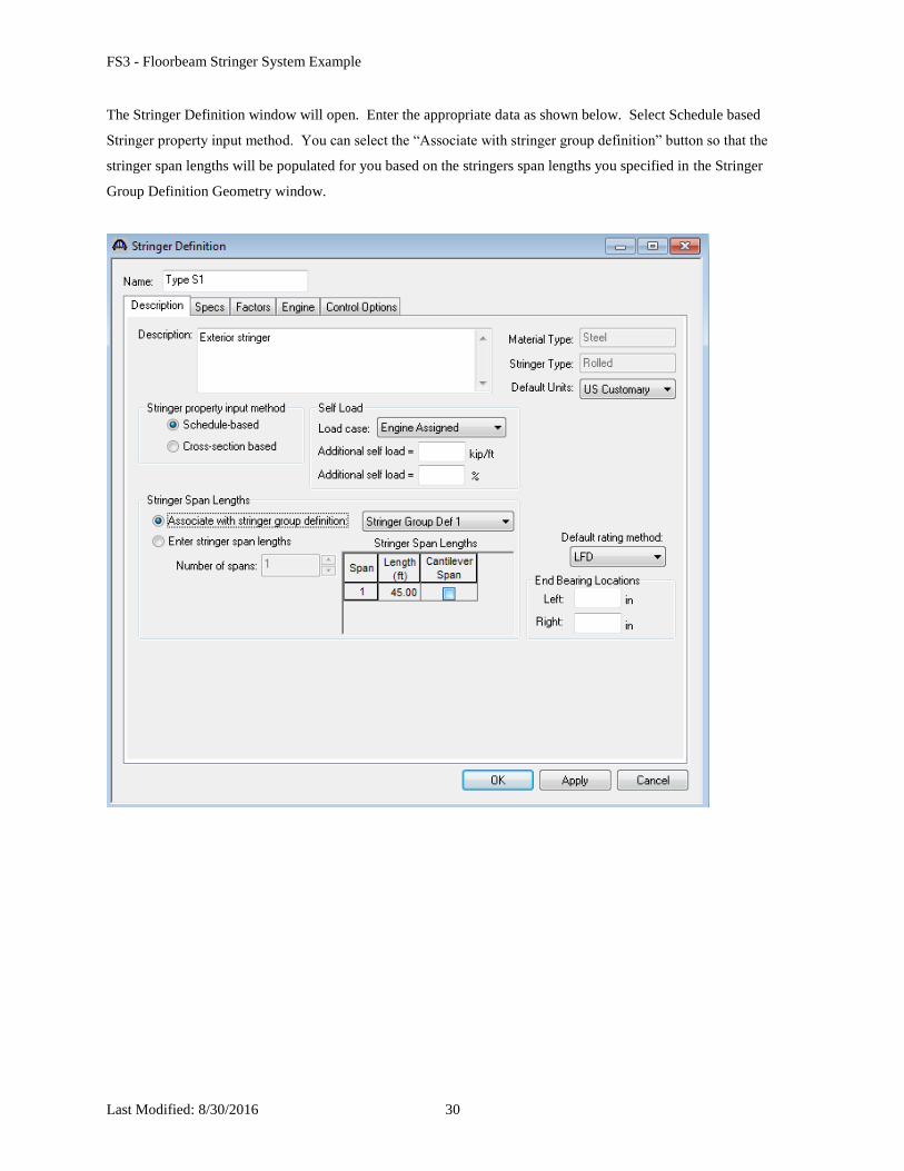
The Stringer Definition window will open. Enter the appropriate data as shown below. Select Schedule based
Stringer property input method. You can select the “Associate with stringer group definition” button so that the
stringer span lengths will be populated for you based on the stringers span lengths you specified in the Stringer
Group Definition Geometry window.
FS3 - Floorbeam Stringer System Example
Last Modified: 8/30/2016 31
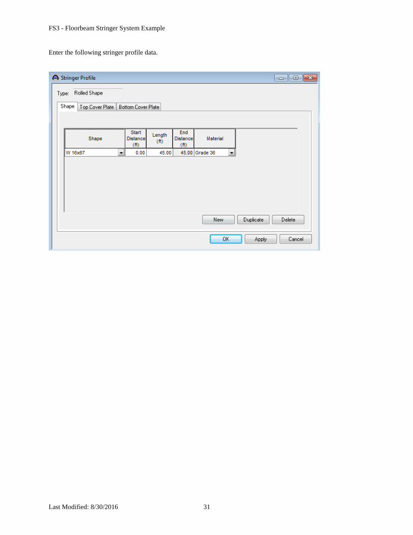
Enter the following stringer profile data.
FS3 - Floorbeam Stringer System Example
Last Modified: 8/30/2016 32
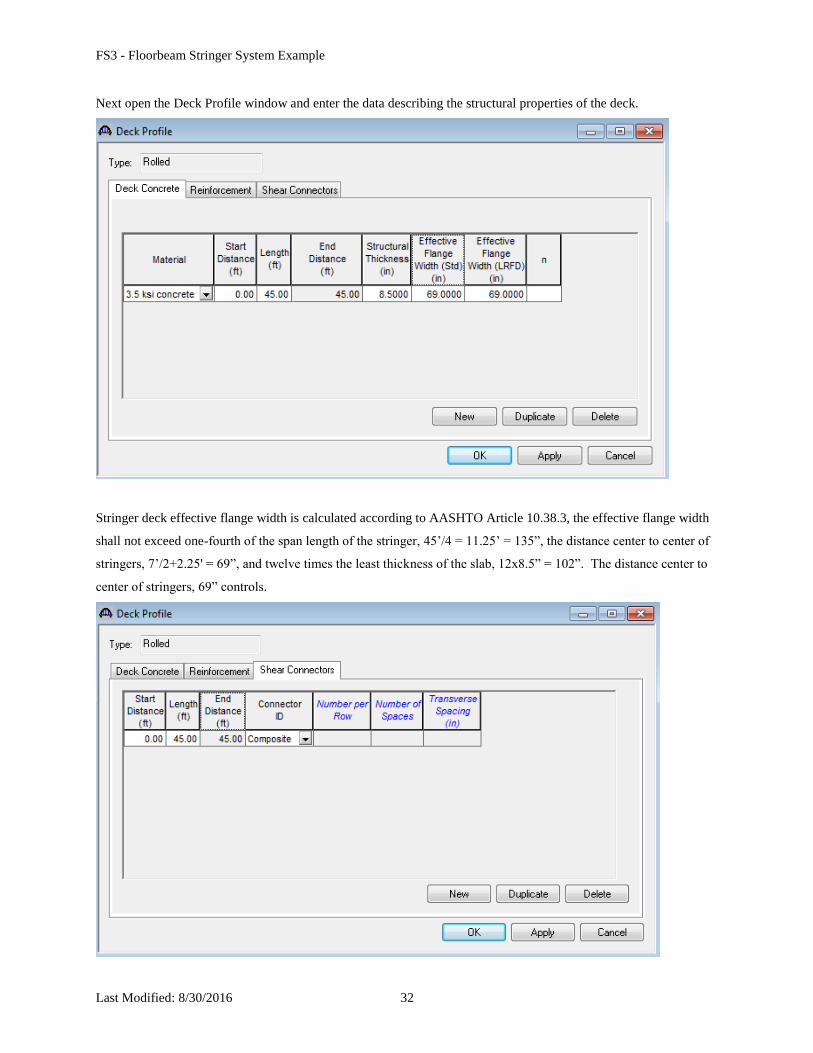
Next open the Deck Profile window and enter the data describing the structural properties of the deck.
Stringer deck effective flange width is calculated according to AASHTO Article 10.38.3, the effective flange width
shall not exceed one-fourth of the span length of the stringer, 45’/4 = 11.25’ = 135”, the distance center to center of
stringers, 7’/2+2.25' = 69”, and twelve times the least thickness of the slab, 12x8.5” = 102”. The distance center to
center of stringers, 69” controls.
FS3 - Floorbeam Stringer System Example
Last Modified: 8/30/2016 33
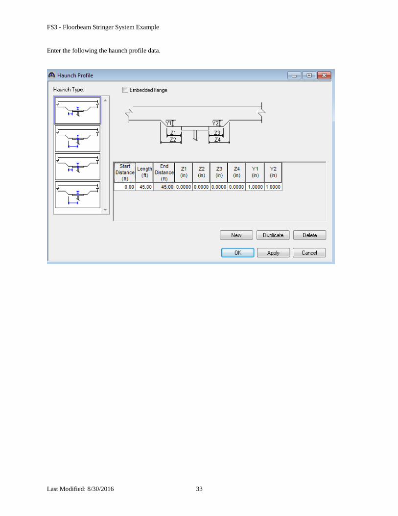
Enter the following the haunch profile data.
FS3 - Floorbeam Stringer System Example
Last Modified: 8/30/2016 34
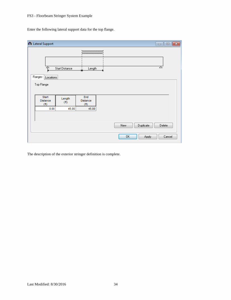
Enter the following lateral support data for the top flange.
The description of the exterior stringer definition is complete.
FS3 - Floorbeam Stringer System Example
Last Modified: 8/30/2016 35
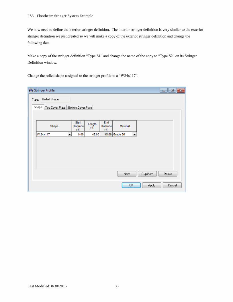
We now need to define the interior stringer definition. The interior stringer definition is very similar to the exterior
stringer definition we just created so we will make a copy of the exterior stringer definition and change the
following data.
Make a copy of the stringer definition “Type S1” and change the name of the copy to “Type S2” on its Stringer
Definition window.
Change the rolled shape assigned to the stringer profile to a “W24x117”.
FS3 - Floorbeam Stringer System Example
Last Modified: 8/30/2016 36
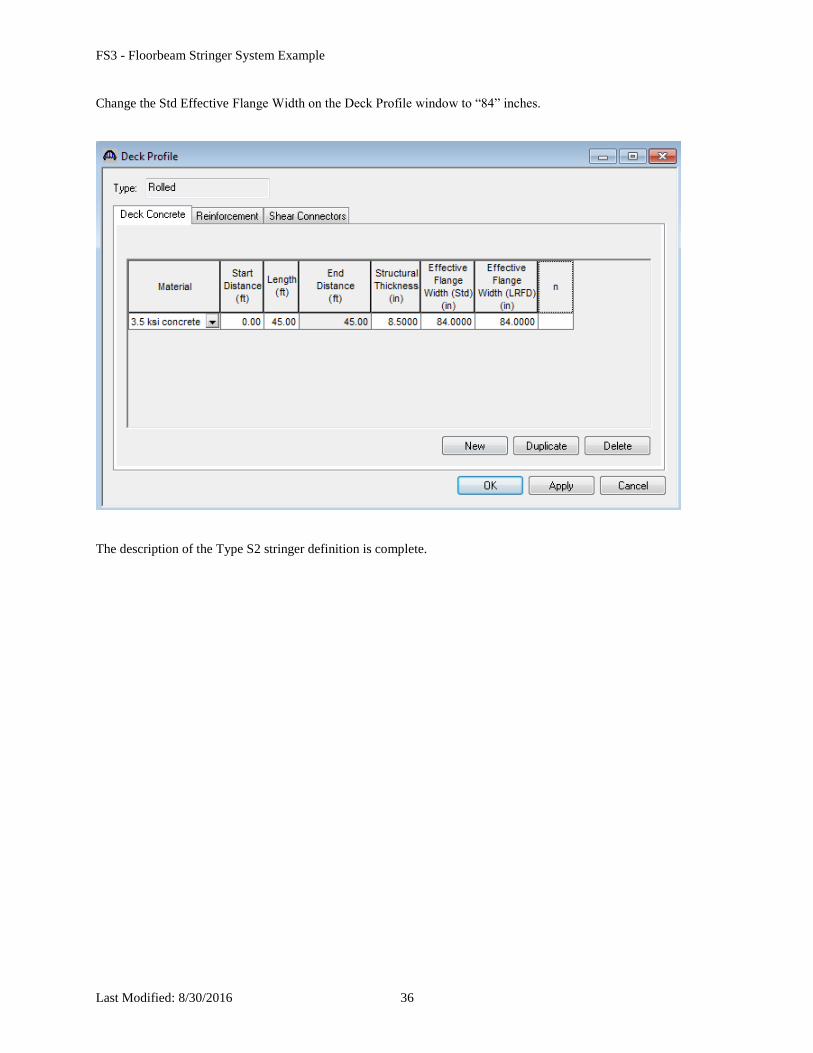
Change the Std Effective Flange Width on the Deck Profile window to “84” inches.
The description of the Type S2 stringer definition is complete.
FS3 - Floorbeam Stringer System Example
Last Modified: 8/30/2016 37
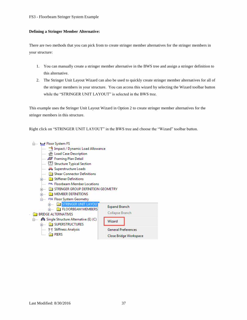
Defining a Stringer Member Alternative:
There are two methods that you can pick from to create stringer member alternatives for the stringer members in
your structure:
1. You can manually create a stringer member alternative in the BWS tree and assign a stringer definition to
this alternative.
2. The Stringer Unit Layout Wizard can also be used to quickly create stringer member alternatives for all of
the stringer members in your structure. You can access this wizard by selecting the Wizard toolbar button
while the “STRINGER UNIT LAYOUT” is selected in the BWS tree.
This example uses the Stringer Unit Layout Wizard in Option 2 to create stringer member alternatives for the
stringer members in this structure.
Right click on “STRINGER UNIT LAYOUT” in the BWS tree and choose the “Wizard” toolbar button.
FS3 - Floorbeam Stringer System Example
Last Modified: 8/30/2016 38
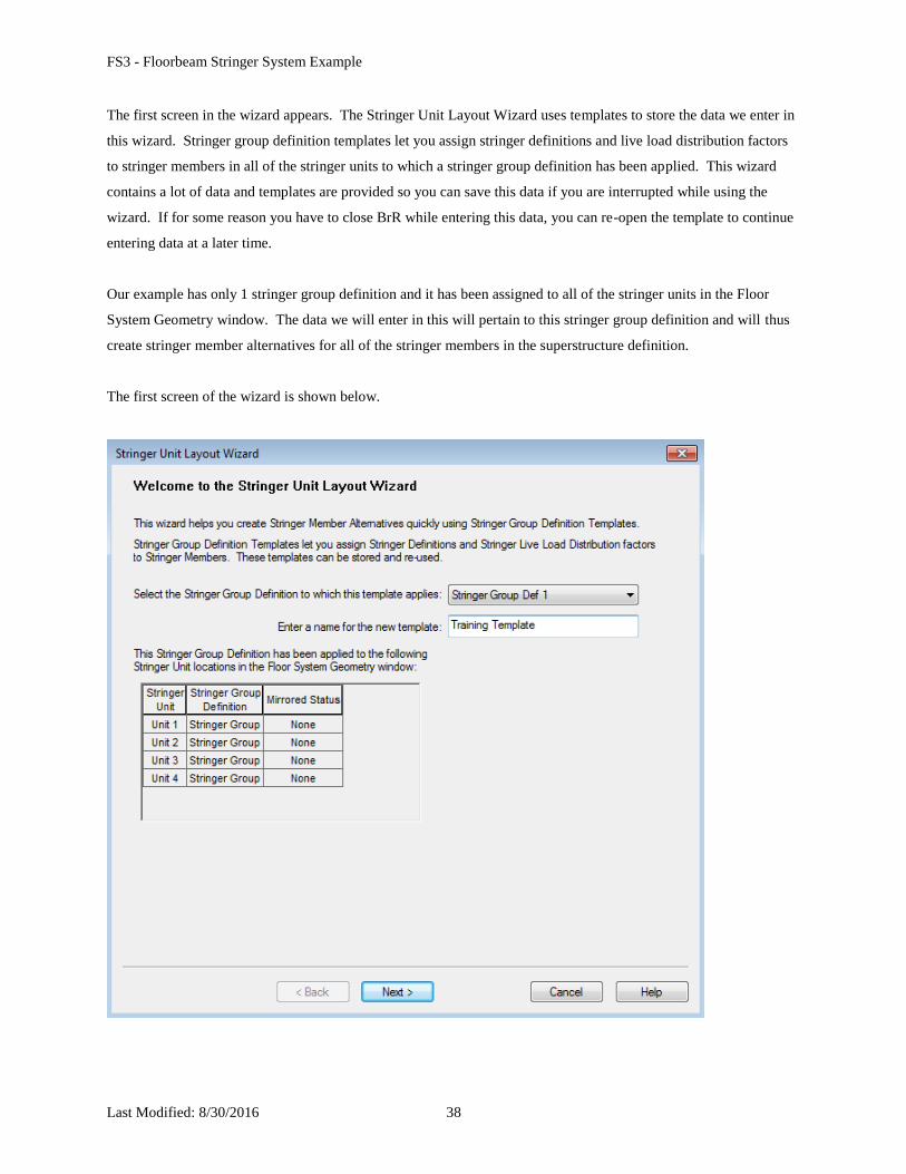
The first screen in the wizard appears. The Stringer Unit Layout Wizard uses templates to store the data we enter in
this wizard. Stringer group definition templates let you assign stringer definitions and live load distribution factors
to stringer members in all of the stringer units to which a stringer group definition has been applied. This wizard
contains a lot of data and templates are provided so you can save this data if you are interrupted while using the
wizard. If for some reason you have to close BrR while entering this data, you can re-open the template to continue
entering data at a later time.
Our example has only 1 stringer group definition and it has been assigned to all of the stringer units in the Floor
System Geometry window. The data we will enter in this will pertain to this stringer group definition and will thus
create stringer member alternatives for all of the stringer members in the superstructure definition.
The first screen of the wizard is shown below.
FS3 - Floorbeam Stringer System Example
Last Modified: 8/30/2016 39
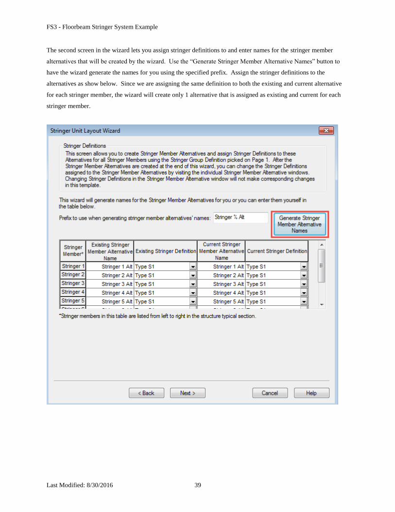
The second screen in the wizard lets you assign stringer definitions to and enter names for the stringer member
alternatives that will be created by the wizard. Use the “Generate Stringer Member Alternative Names” button to
have the wizard generate the names for you using the specified prefix. Assign the stringer definitions to the
alternatives as show below. Since we are assigning the same definition to both the existing and current alternative
for each stringer member, the wizard will create only 1 alternative that is assigned as existing and current for each
stringer member.
FS3 - Floorbeam Stringer System Example
Last Modified: 8/30/2016 40
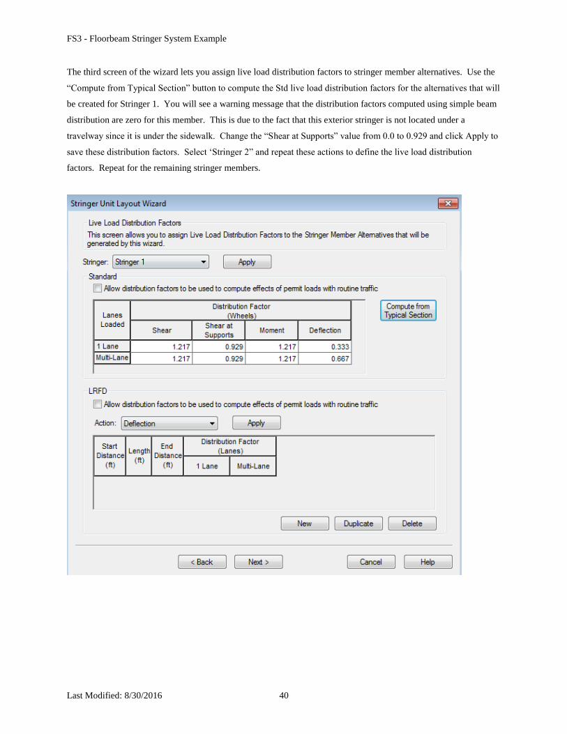
The third screen of the wizard lets you assign live load distribution factors to stringer member alternatives. Use the
“Compute from Typical Section” button to compute the Std live load distribution factors for the alternatives that will
be created for Stringer 1. You will see a warning message that the distribution factors computed using simple beam
distribution are zero for this member. This is due to the fact that this exterior stringer is not located under a
travelway since it is under the sidewalk. Change the “Shear at Supports” value from 0.0 to 0.929 and click Apply to
save these distribution factors. Select ‘Stringer 2” and repeat these actions to define the live load distribution
factors. Repeat for the remaining stringer members.
FS3 - Floorbeam Stringer System Example
Last Modified: 8/30/2016 41
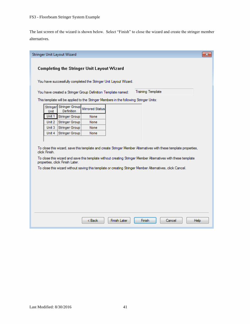
The last screen of the wizard is shown below. Select “Finish” to close the wizard and create the stringer member
alternatives.
FS3 - Floorbeam Stringer System Example
Last Modified: 8/30/2016 42
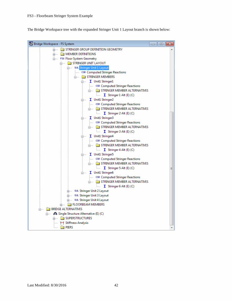
The Bridge Workspace tree with the expanded Stringer Unit 1 Layout branch is shown below:
FS3 - Floorbeam Stringer System Example
Last Modified: 8/30/2016 43
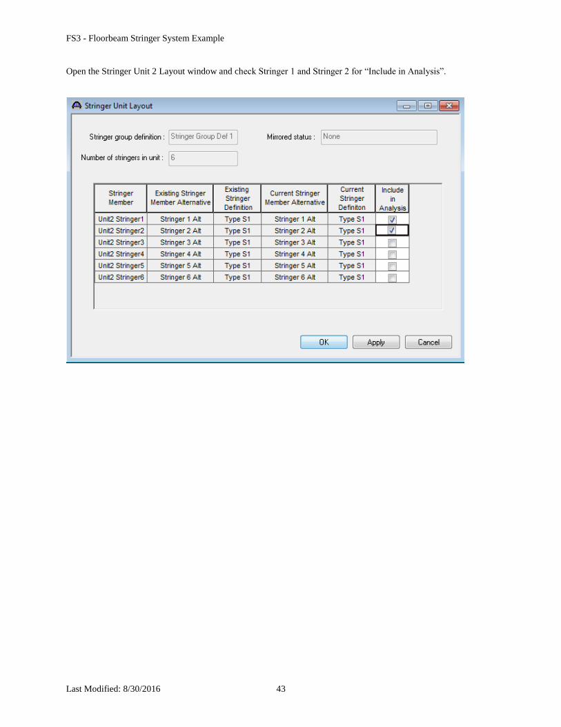
Open the Stringer Unit 2 Layout window and check Stringer 1 and Stringer 2 for “Include in Analysis”.
FS3 - Floorbeam Stringer System Example
Last Modified: 8/30/2016 44
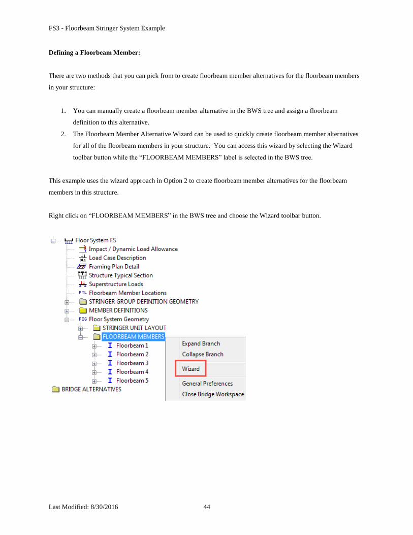
Defining a Floorbeam Member:
There are two methods that you can pick from to create floorbeam member alternatives for the floorbeam members
in your structure:
1. You can manually create a floorbeam member alternative in the BWS tree and assign a floorbeam
definition to this alternative.
2. The Floorbeam Member Alternative Wizard can be used to quickly create floorbeam member alternatives
for all of the floorbeam members in your structure. You can access this wizard by selecting the Wizard
toolbar button while the “FLOORBEAM MEMBERS” label is selected in the BWS tree.
This example uses the wizard approach in Option 2 to create floorbeam member alternatives for the floorbeam
members in this structure.
Right click on “FLOORBEAM MEMBERS” in the BWS tree and choose the Wizard toolbar button.
FS3 - Floorbeam Stringer System Example
Last Modified: 8/30/2016 45
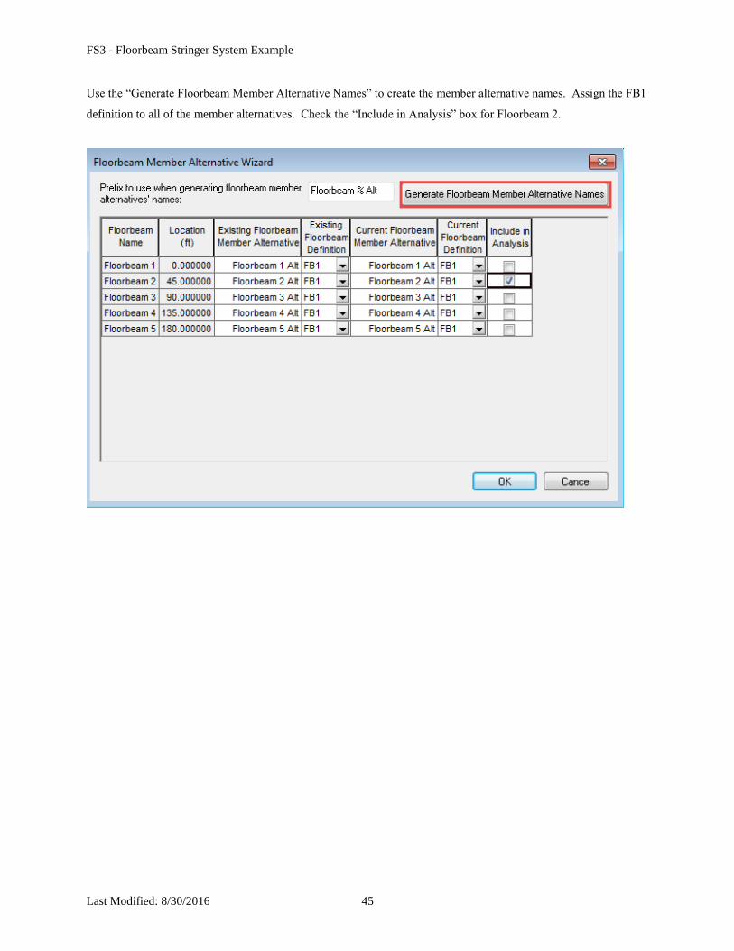
Use the “Generate Floorbeam Member Alternative Names” to create the member alternative names. Assign the FB1
definition to all of the member alternatives. Check the “Include in Analysis” box for Floorbeam 2.
FS3 - Floorbeam Stringer System Example
Last Modified: 8/30/2016 46
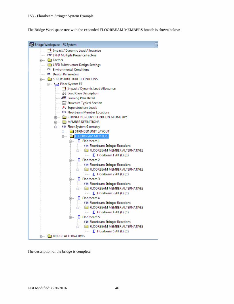
The Bridge Workspace tree with the expanded FLOORBEAM MEMBERS branch is shown below:
The description of the bridge is complete.
FS3 - Floorbeam Stringer System Example
Last Modified: 8/30/2016 47
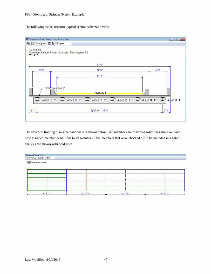
The following is the structure typical section schematic view.
The structure framing plan schematic view is shown below. All members are drawn as solid lines since we have
now assigned member definitions to all members. The members that were checked off to be included in a batch
analysis are shown with bold lines.
FS3 - Floorbeam Stringer System Example
Last Modified: 8/30/2016 48
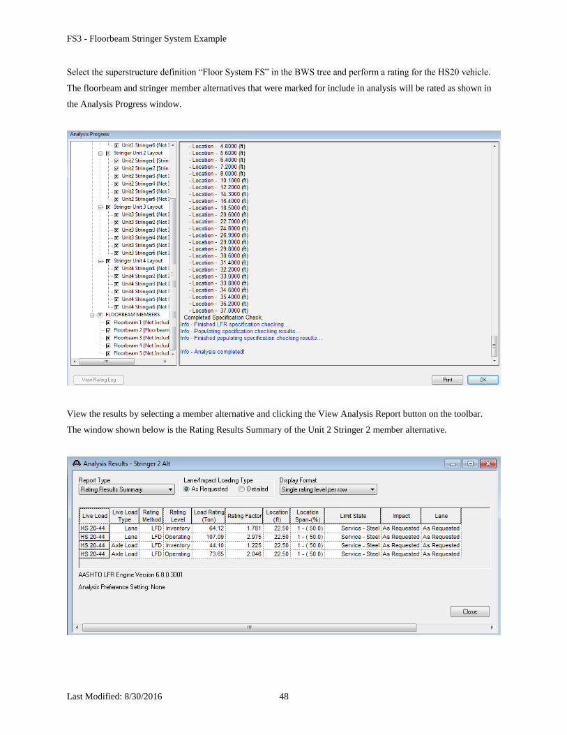
Select the superstructure definition “Floor System FS” in the BWS tree and perform a rating for the HS20 vehicle.
The floorbeam and stringer member alternatives that were marked for include in analysis will be rated as shown in
the Analysis Progress window.
View the results by selecting a member alternative and clicking the View Analysis Report button on the toolbar.
The window shown below is the Rating Results Summary of the Unit 2 Stringer 2 member alternative.
FS3 - Floorbeam Stringer System Example
Last Modified: 8/30/2016 49
Floorbeam 2 supports the stringers in both Stringer Unit 1 and Stringer Unit 2. Part of the analysis of Floorbeam 2
involves the dead load transferred from the stringers to the floorbeam. If the stringer dead load reactions to be used
in a floorbeam analysis do not exist or are not up to date or do not have a user defined override value, BrR will
trigger a dead load analysis of the stringer prior to initiating the floorbeam analysis. Then a “Virtual” stringer
analysis is run. This analysis is run to obtain the live load reactions from the stringers the floorbeam supports. For
this virtual analysis, the stringer cross section is assumed as prismatic and only the stringer span lengths and live
load are actually obtained from user input. Once the live load reaction from the stringers is obtained, an analysis of
Floorbeam 2 is run.
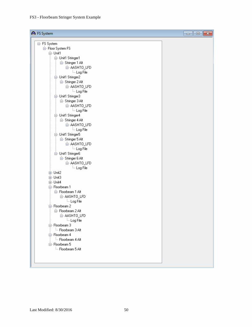
The following shows the View Latest Analysis Output window after a rating of the superstructure definition is
performed. An analysis of each of the stringers that the floorbeam supports has been performed to obtain the
stringer dead load reactions on the floorbeam even though we only marked the “Unit 2 Stringer 1” and “Unit 2
Stringer 2” members to be included in the analysis.
If we were to analyze the superstructure definition again without closing the Bridge Workspace in between analyses
or making any changes to the data for these stringer members, analyses of the stringers in Stringer Units 1 and 2 for
their dead load reactions would not be performed again since that data is currently available in memory and up-to-
date.
FS3 - Floorbeam Stringer System Example
Last Modified: 8/30/2016 50
FS3 - Floorbeam Stringer System Example
Last Modified: 8/30/2016 51
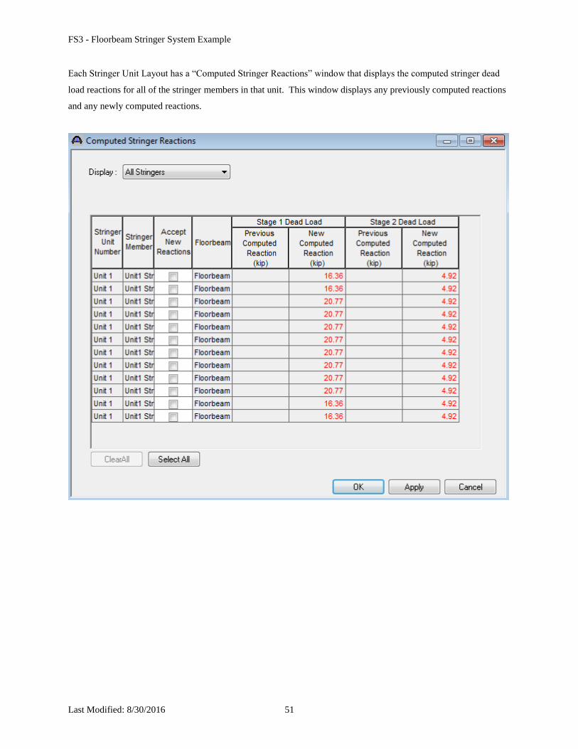
Each Stringer Unit Layout has a “Computed Stringer Reactions” window that displays the computed stringer dead
load reactions for all of the stringer members in that unit. This window displays any previously computed reactions
and any newly computed reactions.
FS3 - Floorbeam Stringer System Example
Last Modified: 8/30/2016 52
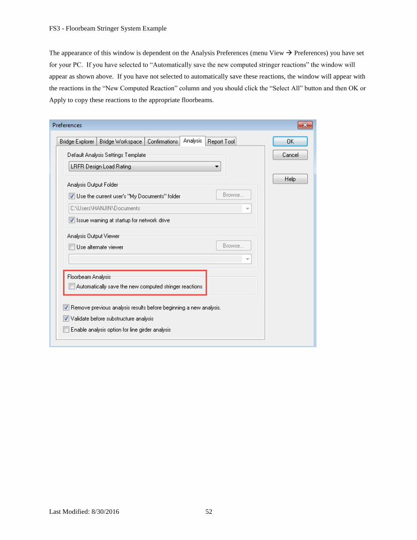
The appearance of this window is dependent on the Analysis Preferences (menu View Preferences) you have set
for your PC. If you have selected to “Automatically save the new computed stringer reactions” the window will
appear as shown above. If you have not selected to automatically save these reactions, the window will appear with
the reactions in the “New Computed Reaction” column and you should click the “Select All” button and then OK or
Apply to copy these reactions to the appropriate floorbeams.
FS3 - Floorbeam Stringer System Example
Last Modified: 8/30/2016 53
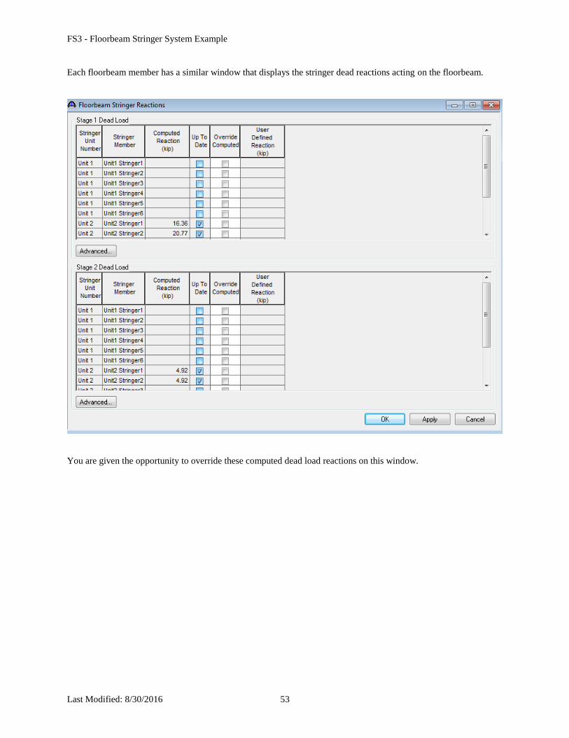
Each floorbeam member has a similar window that displays the stringer dead reactions acting on the floorbeam.
You are given the opportunity to override these computed dead load reactions on this window.