Embed Size (px)
Citation preview
Form Number A6206 Part Number D301232X012 September 2009
FloBoss™ 107 Flow Manager Instruction Manual
Remote Automation Solutions

FloBoss 107 Instruction Manual
ii Revised Sep-09
Revision Tracking Sheet
September 2009
This manual may be revised periodically to incorporate new or updated information. The revision date of each page appears at the bottom of the page opposite the page number. A change in revision date to any page also changes the date of the manual that appears on the front cover. Listed below is the revision date of each page (if applicable):
Page Revision All Pages Sep-09 Initial issue Feb-07
© 2007-2009 Remote Automation Solutions, division of Emerson Process Management. All rights reserved.
NOTICE Remote Automation Solutions (“RAS”), division of Emerson Process Management shall not be liable for technical or editorial errors in this manual or omissions from this manual. RAS MAKES NO WARRANTIES, EXPRESSED OR IMPLIED, INCLUDING THE IMPLIED WARRANTIES OF MERCHANTABILITY AND FITNESS FOR A PARTICULAR PURPOSE WITH RESPECT TO THIS MANUAL AND, IN NO EVENT SHALL RAS BE LIABLE FOR ANY INCIDENTAL, PUNITIVE, SPECIAL OR CONSEQUENTIAL DAMAGES INCLUDING, BUT NOT LIMITED TO, LOSS OF PRODUCTION, LOSS OF PROFITS, LOSS OF REVENUE OR USE AND COSTS INCURRED INCLUDING WITHOUT LIMITATION FOR CAPITAL, FUEL AND POWER, AND CLAIMS OF THIRD PARTIES.
Bristol, Inc., Bristol Babcock Ltd, Bristol Canada, BBI SA de CV and the Flow Computer Division are wholly owned subsidiaries of Emerson Electric Co. doing business as Remote Automation Solutions (“RAS”), a division of Emerson Process Management. FloBoss, ROCLINK, Bristol, Bristol Babcock, ControlWave, TeleFlow and Helicoid are trademarks of RAS. AMS, PlantWeb and the PlantWeb logo are marks of Emerson Electric Co. The Emerson logo is a trademark and service mark of the Emerson Electric Co. All other trademarks are property of their respective owners.
The contents of this publication are presented for informational purposes only. While every effort has been made to ensure informational accuracy, they are not to be construed as warranties or guarantees, express or implied, regarding the products or services described herein or their use or applicability. RAS reserves the right to modify or improve the designs or specifications of such products at any time without notice. All sales are governed by RAS’ terms and conditions which are available upon request.
RAS does not assume responsibility for the selection, use or maintenance of any product. Responsibility for proper selection, use and maintenance of any RAS product remains solely with the purchaser and end-user.

FloBoss 107 Instruction Manual
Revised Sep-09 Contents iii
Contents
Chapter 1 – General Information 1-1
1.1 Scope of Manual .............................................................................................................. 1-2 1.2 FloBoss 107 Overview ..................................................................................................... 1-2 1.3 Hardware.......................................................................................................................... 1-5
1.3.1 Processor and Memory...................................................................................... 1-6 1.3.2 Backplane .......................................................................................................... 1-6 1.3.3 Expansion Rack ................................................................................................. 1-6 1.3.4 Central Processing Unit (CPU) .......................................................................... 1-6 1.3.5 Battery and Super-capacitor .............................................................................. 1-8 1.3.6 Built-in Inputs and Outputs................................................................................. 1-8 1.3.7 Built-in Communications .................................................................................... 1-8 1.3.8 Built-in Resistance Thermal Device (RTD) ...................................................... 1-10 1.3.9 Built-in Loop Output Power .............................................................................. 1-10 1.3.10 Optional Inputs and Outputs ............................................................................ 1-10 1.3.11 Optional Communication Modules – COM3 .................................................... 1-11 1.3.12 Optional Multi-Variable Sensor (MVS)............................................................. 1-12 1.3.13 Optional Integral Sensors ................................................................................ 1-12 1.3.14 Optional License Key ....................................................................................... 1-12 1.3.15 Optional Enclosures......................................................................................... 1-12 1.3.16 Optional LCD Touchpad .................................................................................. 1-12
1.4 Firmware ........................................................................................................................ 1-13 1.4.1 History Points................................................................................................... 1-14 1.4.2 Alarm Log......................................................................................................... 1-15 1.4.3 Event Log......................................................................................................... 1-16 1.4.4 Security ............................................................................................................ 1-16 1.4.5 I/O Database.................................................................................................... 1-17 1.4.6 Function Sequence Tables (FST).................................................................... 1-17 1.4.7 PID Control....................................................................................................... 1-17 1.4.8 Spontaneous-Report-By-Exception (SRBX) Alarming..................................... 1-18 1.4.9 Softpoints ......................................................................................................... 1-18 1.4.10 Opcodes........................................................................................................... 1-18 1.4.11 Pass Through Communications....................................................................... 1-18 1.4.12 ROC and Modbus Protocols ............................................................................ 1-19 1.4.13 User C Programs ............................................................................................. 1-19
1.5 ROCLINK™ 800 Configuration Software ........................................................................ 1-19 1.6 Product Electronics ........................................................................................................ 1-21
1.6.1 Real-Time Clock .............................................................................................. 1-21 1.6.2 Diagnostic Monitoring ...................................................................................... 1-21 1.6.3 Automatic Self Tests ........................................................................................ 1-22 1.6.4 Low Power Mode ............................................................................................. 1-22
1.7 Flow Measurements....................................................................................................... 1-22 1.8 Additional Technical Information.................................................................................... 1-23
Chapter 2 – Installation and Use 2-1 2.1 Installation Requirements................................................................................................. 2-1
2.1.1 Environmental Requirements............................................................................. 2-1 2.1.2 Site Requirements ............................................................................................. 2-2 2.1.3 Compliance with Hazardous Area Standards .................................................... 2-4 2.1.4 Power Installation Requirements ....................................................................... 2-4 2.1.5 Grounding Installation Requirements ................................................................ 2-5

FloBoss 107 Instruction Manual
iv Contents Revised Sep-09
2.1.6 I/O Wiring Requirements.................................................................................... 2-6 2.2 Installing the FloBoss 107 and Expansion Rack.............................................................. 2-7
2.2.1 Required Tools................................................................................................... 2-7 2.2.2 Installing the FloBoss 107 without an Expansion Rack ..................................... 2-7 2.2.3 Installing the FloBoss with an Expansion Rack ................................................. 2-8 2.2.4 Removing an Expansion Rack......................................................................... 2-10 2.2.5 Removing and Installing Module Slot Covers.................................................. 2-10 2.2.6 Removing and Installing Wire Channel Covers ............................................... 2-11
2.3 Memory Backup Battery................................................................................................. 2-11 2.3.1 Removing and Installing the Battery ................................................................ 2-12
2.4 Central Processor Unit (CPU)........................................................................................ 2-13 2.4.1 Removing the CPU Module ............................................................................. 2-14 2.4.2 Installing the CPU Module ............................................................................... 2-15 2.4.3 Resetting the CPU ........................................................................................... 2-15
2.5 License Keys.................................................................................................................. 2-15 2.6 Startup and Operation.................................................................................................... 2-16
2.6.1 Startup ............................................................................................................. 2-16 2.6.2 Operation ......................................................................................................... 2-16
Chapter 3 – Power Connections 3-1 3.1 Power Input Descriptions ................................................................................................. 3-1 3.2 Determining Power Consumption .................................................................................... 3-3
3.2.1 Summary............................................................................................................ 3-6 3.3 Wiring Connections .......................................................................................................... 3-6 3.4 Wiring Power to the CPU Module .................................................................................... 3-7
Chapter 4 – Inputs and Outputs 4-1 4.1 I/O Description ................................................................................................................. 4-1 4.2 Installing a Module ........................................................................................................... 4-4 4.3 Removing a Module ......................................................................................................... 4-6 4.4 Wiring a Module ............................................................................................................... 4-6 4.5 Selecting the Type of I/O.................................................................................................. 4-7 4.6 Analog Inputs (AI) ............................................................................................................ 4-9
4.6.1 Wiring the Analog Inputs.................................................................................... 4-9 4.7 8-Point Analog Input/Digital Input (AI/DI) Module .......................................................... 4-11
4.7.1 Wiring the 8-Point AI/DI ................................................................................... 4-11 4.8 Analog Outputs (AO)...................................................................................................... 4-13
4.8.1 Wiring the Analog Outputs............................................................................... 4-13 4.9 Discrete Inputs (DI) ........................................................................................................ 4-14
4.9.1 Wiring the Discrete Inputs................................................................................ 4-15 4.10 Discrete Outputs (DO).................................................................................................... 4-15
4.10.1 Wiring the Discrete Outputs............................................................................. 4-16 4.11 Discrete Outputs Relay (DOR) Module.......................................................................... 4-17
4.11.1 Wiring the Discrete Output Relays................................................................... 4-18 4.12 Pulse Inputs (PI)............................................................................................................. 4-19
4.12.1 Wiring the Pulse Inputs .................................................................................... 4-19 4.13 Application (APP 485) Module ....................................................................................... 4-20
4.13.1 Wiring the Application Module ......................................................................... 4-20 4.14 Resistance Temperature Detector (RTD) Input ............................................................. 4-21
4.14.1 Wiring the RTD Input ....................................................................................... 4-22 4.15 6-Point AO/DO Module .................................................................................................. 4-23
4.15.1 Wiring the 6-Point AO/DO Module................................................................... 4-23 4.16 HART® Module............................................................................................................... 4-24
4.16.1 Wiring the HART Module ................................................................................. 4-25 4.17 Resistance Temperature Detector (RTD) Module ......................................................... 4-26
4.17.1 Wiring the RTD Module.................................................................................... 4-26

FloBoss 107 Instruction Manual
Revised Sep-09 Contents v
4.18 Related Technical Specifications ................................................................................... 4-27
Chapter 5 – Communications 5-1 5.1 Communications Overview .............................................................................................. 5-1 5.2 Installing/Removing a Communication Module................................................................ 5-4 5.3 Wiring the Local Operator Interface (LOI) Port ................................................................ 5-5
5.3.1 Using the LOI ..................................................................................................... 5-6 5.4 Wiring EIA-485 (RS-485) Communications ..................................................................... 5-6 5.5 Wiring EIA-232 (RS-232) Communications ..................................................................... 5-7 5.6 Liquid Crystal Display (LCD) Touchpad........................................................................... 5-8 5.7 Enhanced Communication Module (ECM)....................................................................... 5-9
5.7.1 Activating the USB Port ................................................................................... 5-10 5.8 Dial-Up Modem Module ................................................................................................. 5-15 5.9 Related Technical Specifications ................................................................................... 5-16
Chapter 6 – Sensors and Transducers 6-1 6.1 Multi-Variable Sensor (MVS) Module Overview............................................................... 6-1
6.1.1 Installing/Removing an MVS Module................................................................. 6-3 6.1.2 Configuring a Multi-drop MVS Module Setup .................................................... 6-3 6.1.3 Lightning Protection ........................................................................................... 6-6
6.2 Dual Variable Sensor (DVS) Overview ............................................................................ 6-6 6.2.1 Installing/Removing a DVS ................................................................................ 6-7 6.2.2 Physically Connecting a DVS ............................................................................ 6-9 6.2.3 Configuring a DVS ........................................................................................... 6-10
6.3 Pressure Module (PM) Overview ................................................................................... 6-11 6.3.1 Installing/Removing a Pressure Module .......................................................... 6-12 6.3.2 Configuring a Pressure Module ....................................................................... 6-13
Chapter 7 – Troubleshooting 7-1 7.1 General Guidelines .......................................................................................................... 7-1 7.2 Graphical User Interface (GUI) ........................................................................................ 7-2 7.3 Checklists ......................................................................................................................... 7-3
7.3.1 LEDs .................................................................................................................. 7-3 7.3.2 Serial Communications ...................................................................................... 7-4 7.3.3 Inputs/Outputs.................................................................................................... 7-4 7.3.4 Preserving Configuration and Log Data............................................................. 7-5 7.3.5 ROCLINK 800 Configuration Software .............................................................. 7-6 7.3.6 Powering Up....................................................................................................... 7-6 7.3.7 Multi-Variable Sensor (MVS) ............................................................................. 7-7 7.3.8 Resistance Temperature Detector (RTD) .......................................................... 7-7
7.4 Procedures ....................................................................................................................... 7-8 7.4.1 Resetting the FB107 .......................................................................................... 7-8 7.4.2 Restarting and Reconfiguring the FB107........................................................... 7-8 7.4.3 Troubleshooting Analog Inputs .......................................................................... 7-9 7.4.4 Troubleshooting Analog Outputs ..................................................................... 7-10 7.4.5 Troubleshooting Discrete Inputs ...................................................................... 7-11 7.4.6 Troubleshooting Discrete Outputs ................................................................... 7-11 7.4.7 Troubleshooting Pulse Inputs .......................................................................... 7-12 7.4.8 Troubleshooting RTD Inputs ............................................................................ 7-12 7.4.9 Troubleshooting the Multi-Variable Sensor (MVS) .......................................... 7-14 7.4.10 Troubleshooting the Enhanced Comm Module (ECM).................................... 7-15 7.4.11 Troubleshooting the Dual Variable Sensor (DVS) ........................................... 7-15 7.4.12 Troubleshooting the Pressure Module (PM) .................................................... 7-16 7.4.13 Troubleshooting AI/DI ...................................................................................... 7-16

FloBoss 107 Instruction Manual
vi Contents Revised Sep-09
7.4.14 Troubleshooting the Discrete Output Relay (DOR) ......................................... 7-17
Appendix A – Glossary A-1
Index I-1

FloBoss 107 Instruction Manual
Revised Sep-09 General Information 1-1
Chapter 1 – General Information
This manual describes the FloBoss™ 107 Flow Manager (“FB107”), part of the family of FloBoss flow computers manufactured by Remote Automation Solutions, a division of Emerson Process Management. For information about the software you use to configure the FB107, refer to the ROCLINK™ 800, Configuration Software User Manual (for FloBoss 107) (Form A6217).
This chapter provides an overview of the FB107 and its components.
In This Chapter
1.1 Scope of Manual.................................................................................1-2 1.2 FloBoss 107 Overview........................................................................1-2 1.3 Hardware ............................................................................................1-5
1.3.1 Processor and Memory..........................................................1-6 1.3.2 Backplane ..............................................................................1-6 1.3.3 Expansion Rack.....................................................................1-6 1.3.4 Central Processing Unit (CPU)..............................................1-6 1.3.5 Battery and Super-capacitor ..................................................1-8 1.3.6 Built-in Inputs and Outputs ....................................................1-8 1.3.7 Built-in Communications ........................................................1-8 1.3.8 Built-in Resistance Thermal Device (RTD)..........................1-10 1.3.9 Built-in Loop Output Power..................................................1-10 1.3.10 Optional Inputs and Outputs ................................................1-10 1.3.11 Optional Communication Modules – COM3 ........................1-11 1.3.12 Optional Multi-Variable Sensor (MVS).................................1-12 1.3.13 Optional Integral Sensors ....................................................1-12 1.3.14 Optional License Key...........................................................1-12 1.3.15 Optional Enclosures.............................................................1-12 1.3.16 Optional LCD Touchpad ......................................................1-12
1.4 Firmware ...........................................................................................1-13 1.4.1 History Points.......................................................................1-14 1.4.2 Alarm Log.............................................................................1-15 1.4.3 Event Log.............................................................................1-16 1.4.4 Security ................................................................................1-16 1.4.5 I/O Database........................................................................1-17 1.4.6 Function Sequence Tables (FST)........................................1-17 1.4.7 PID Control ..........................................................................1-17 1.4.8 Spontaneous-Report-By-Exception (SRBX) Alarming ........1-18 1.4.9 Softpoints .............................................................................1-18 1.4.10 Opcodes...............................................................................1-18 1.4.11 Pass Through Communications ..........................................1-18 1.4.12 ROC and Modbus Protocols ................................................1-19 1.4.13 User C Programs .................................................................1-19
1.5 ROCLINK™ 800 Configuration Software...........................................1-19 1.6 Product Electronics...........................................................................1-21
1.6.1 Real-Time Clock ..................................................................1-21 1.6.2 Diagnostic Monitoring ..........................................................1-21 1.6.3 Automatic Self Tests............................................................1-22 1.6.4 Low Power Mode .................................................................1-22
1.7 Flow Measurements .........................................................................1-22 1.8 Additional Technical Information.......................................................1-23
FloBoss 107 Instruction Manual
1-2 General Information Revised Sep-09
1.1 Scope of Manual This manual contains the following chapters:
Chapter 1 General Information
Provides an overview of the hardware and firmware for the FB107 base unit and the expansion rack.
Chapter 2 Installation and Use
Provides information on installation, tools, wiring, and other essential elements of the FB107.
Chapter 3 Power Connections
Provides information on determining power requirements for the FB107.
Chapter 4 Inputs and Outputs
Provides information for the input/output (I/O) modules, CPU I/O assembly, and the RTD input.
Chapter 5 Communications
Provides information for the built-in communication ports and the optional communication modules.
Chapter 6 Sensors and Transducers
Provides information on the optional Multi-Variable Sensor (MVS), Dual Variable Sensor (DVS), and Pulse Input modules.
Chapter 7 Troubleshooting
Provides information on diagnosing and correcting problems.
Glossary Provides definitions of acronyms and terms. Index Provides an alphabetic listing of items and topics
contained in this manual.
1.2 FloBoss 107 Overview A 32-bit microprocessor-based electronic flow computer, the FB107 electronically measures, monitors, and manages flow. This economical flow computer reliably and accurately performs flow calculations, temperature measurements, and data archival.
Note: You configure the functionality of the FB107 and monitor its operation using a personal computer (PC) running ROCLINK 800 (“ROCLINK 800”) software.
The FB107 can measure up to four meter runs through a variety of devices, such as an orifice plate, turbine meter, or other pulse-generating devices. Meter inputs may also use analog transmitters. For multiple differential pressure-run applications, you can add an optional Multiple-Variable Sensor (MVS) module to provide an interface to remote MVS transmitters.
The FB107 performs minute, hourly, daily, and minimum / maximum historical data archival for standard history and a configurable time interval archival for extended history. As the electronic solution to replace traditional paper charting, the FB107 records the corrected flow for differential or pulse counts and stores the data.
The FB107 computes flow for both volume and energy. It provides on-site functionality and supports remote monitoring, measurement, data archival, communications, and control. It stores the results of the flow calculations in memory, which can then be and can be communicated to an external device either on demand or periodically.

FloBoss 107 Instruction Manual
The FB107 design allows you to configure specific applications, including those requiring logic and sequencing control using a Function Sequence Table (FST).
Local (LOI) Communication Port
Slot 2 = I/O, MVS module, or COM module (COM2)
Slot 3 = I/O or MVS module
Slot 0 = CPUModule
CPU I/O Assembly
Slot 1 = I/O, MVS, or COM module (COM3)
Wire Channel Cover
Input PowerConnector
Display Connector
Integral Sensor ConnectorMemory Backup
Battery Connector
Figure 1-1. FloBoss 107 Base Unit
Revised Sep-09 General Information 1-3
FloBoss 107 Instruction Manual
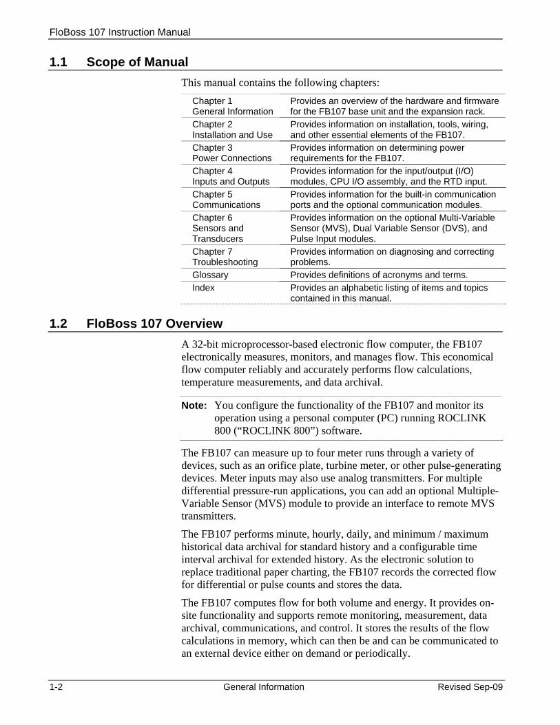
Slot 7 = I/O or MVS module
Slot 4 = I/O or MVS module
Slot 5 = I/O or MVS module
Slot 6 = I/O or MVS module
Wire Channel Cover
Connects to FloBoss 107
base unit
Figure 1-2. FloBoss 107 Expansion Rack
1-4 General Information Revised Sep-09
FloBoss 107 Instruction Manual
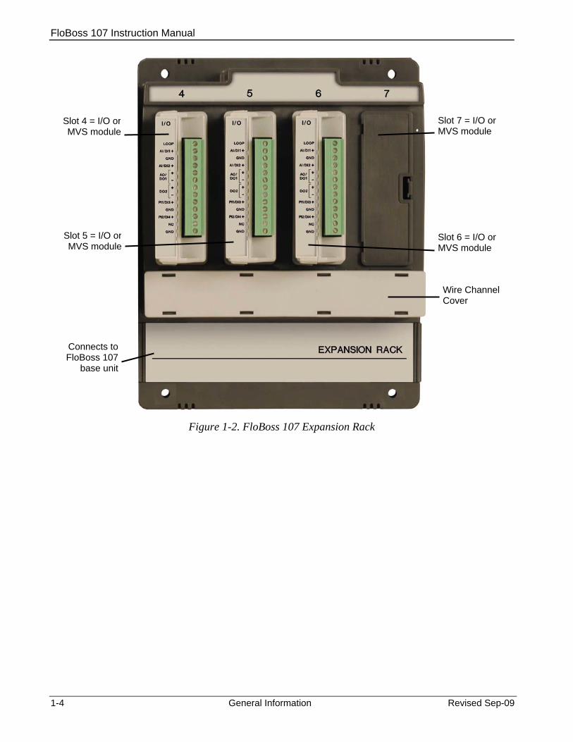
Figure 1-3. FloBoss 107 with Expansion Rack
The FB107 provides the following components and features: 32-bit processor board, inter-connect board, and backplane board. Central processing unit (CPU). Field-upgradeable 2 MB flash ROM (read only memory). 2 MB battery backed-up RAM (random access memory) storage. Two-, three-, or four-wire 100-ohm resistance thermal device (RTD)
input. Battery and super-capacitor backed memory retention to provide
short and longer-term data, configuration, and operational integrity when the FB107 is not in service or is in storage.
Three built-in communication ports. Input power and output loop power. Extensive applications firmware.
1.3 Hardware The FB107 is available with four basic configurations: Non-isolated CPU without I/O. Non-isolated CPU with six points of I/O. Isolated CPU without I/O. Isolated CPU with six points of I/O.
Note: Isolation occurs between the CPU and the field logic. te: Isolation occurs between the CPU and the field logic.
Revised Sep-09 General Information 1-5

FloBoss 107 Instruction Manual
1-6 General Information Revised Sep-09
The FB107 base unit has four slots. Slot 0 is reserved for the CPU module, which provides three communication ports, an RTD, power input, loop power output, system variables, and optional 6 points of I/O.
Slots 1 and 2 can each contain one communication module. Slots 1, 2, and 3 can contain input/outputs (I/O), MVS, and application modules.
1.3.1 Processor and Memory The FB107 derives processing power from a 32-bit CMOS microprocessor. The microprocessor features a single 32-bit internal data bus and a single 16-bit external data bus. The microprocessor has low-power operating modes, including inactivity and low battery condition. The FB107 has high-speed direct memory access.
The FB107 has 2 MB of static random access memory (SRAM) for storing database, historical, configuration, alarms, and events data.
1.3.2 Backplane The backplane board routes signals to and from the CPU to the I/O modules, application modules, expansion rack, the Multi-Variable Sensor, and communication modules.
1.3.3 Expansion Rack The four-slot optional expansion rack (see Figure 1-3) enables the FB107 to expand its I/O capabilities to meet your needs. The expansion rack supports optional I/O, MVS, and application modules.
1.3.4 Central Processing Unit (CPU) The base unit on the FB107 has four slots. Slot 0 is for the CPU module. The CPU provides connections to the field wiring including surge and static discharge protection for the field wiring. Electronics include the RTD circuits and the final I/O drivers/receivers.
The CPU components include: RTD input. Input power. Loop power output. Reset (RST) switch. System variables. Diagnostic monitoring. Real-time clock. Automatic self-tests. Power saving modes. Local operator interface (LOI) EIA-232 (RS-232). EIA-485 (RS-485) communications (COM1).
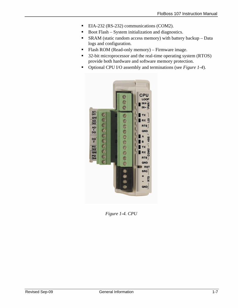
FloBoss 107 Instruction Manual
EIA-232 (RS-232) communications (COM2). Boot Flash – System initialization and diagnostics. SRAM (static random access memory) with battery backup – Data
logs and configuration. Flash ROM (Read-only memory) – Firmware image. 32-bit microprocessor and the real-time operating system (RTOS)
provide both hardware and software memory protection. Optional CPU I/O assembly and terminations (see Figure 1-4).
Figure 1-4. CPU
Revised Sep-09 General Information 1-7

FloBoss 107 Instruction Manual
1-8 General Information Revised Sep-09
1.3.5 Battery and Super-capacitor A super capacitor (“super-cap”) and a coin type battery work together to provide backup power for the static RAM and the real-time clock. This helps to ensure retention of short and longer-term data, configuration, and operational integrity when the FB107 is not in service or is in storage.
For information on replacing the battery, refer to Section 2.5.1, Removing and Installing the Battery.
Note: The super-cap is not field-replaceable.
1.3.6 Built-in Inputs and Outputs The built-in inputs and outputs (I/O) on the CPU consist of a 3- or 4-wire 100-ohm resistance thermal detector (RTD) input interface and five diagnostic analog inputs (AI) that monitor the: Logical voltage. Battery voltage from the backplane voltage input connector. Charge in voltage originating from the CPU power input. System milliamps originating from the power input from the CPU. Board temperature originating at the CPU.
1.3.7 Built-in Communications The FB107 supports up to four communication ports. The base CPU has three built-in communication ports: Local Operator Interface (RS-232C) – LOI for asynchronous serial
communication (Local Port). EIA-485 (RS-485) – COM1 for asynchronous serial communication. EIA-232 (RS-232) – COM2 for serial communication.
Local Operator Interface Port
The Local Operator Interface (LOI) port provides for a direct, local link between the FB107 and a personal computer (PC) through an optional Local Operator Interface Cable using EIA-232 (RS-232C) communications. The LOI local port allows you to access the FB107 for configuration and transfer of stored data. The LOI port is capable of initiating a message in support of Spontaneous-Report-by-Exception (SRBX) alarming.
The LOI is software-configurable with baud rates from 300 to 115.2 K and it uses a DB9 connection.
Note: You can purchase an LOI cable from your sales representative.

FloBoss 107 Instruction Manual
Revised Sep-09 General Information 1-9
The LOI supports ROC or Modbus slave protocol communications. The LOI also supports the log-on security feature of the FB107, if you enable the security on LOI using ROCLINK 800.
Default values for the LOI port are: 19,200 baud rate, 8 data bits, 1 stop bit, no parity, group 1, and address 2.
EIA-485 (RS-485) Serial Communications
COM1
COM1 provides EIA-485 (RS-485) serial communication protocols with baud rates from 300 to 115.2 K. COM1 provides standard differential data transmissions over distances of up to 1220 meter (4000 feet). The EIA-485 (RS-485) drivers are designed for true multi-point applications with multiple devices on a single bus.
Note: COM1 is labeled 485 on the CPU.
Use COM1 to monitor or modify the FB107 from a remote site, using a host or ROCLINK 800. COM1 also supports the log-on security feature of the FB107 if you enable the security on COM1 using ROCLINK 800.
COM1 sends and receives messages using the ROC or Modbus slave and host protocol. COM1 is capable of initiating a message in support of Spontaneous-Report-by-Exception (SRBX) alarming.
Default values for the EIA-485 (RS-485) communications are: 19,200 baud rate, 8 data bits, 1 stop bit, no parity, 10 millisecond key-on delay, and 10 millisecond key-off delay. The maximum baud rate is 115.2 Kbps.
EIA-232 (RS-232) Serial Communications
COM2
COM2 allows for EIA-232 (RS-232) asynchronous serial communication protocols with baud rates from 300 to 115.2 K, host serial interface. COM2 provides standard single-ended data transmission over distances of up to 15 meter (50 feet). Use COM2 to monitor or alter the FB107 from a remote site, using ROCLINK 800. COM2 also supports the log-on security feature of the FB107 if you enable the security on COM2 using ROCLINK 800.
COM2 sends and receives messages using the ROC or Modbus slave or host protocol. COM2 is capable of initiating a message in support of Spontaneous-Report-by-Exception (SRBX) alarming.
Default values for the EIA-232 (RS-232) communications module are: 19,200 baud rate, 8 data bits, 1 stop bit, no parity, 10 millisecond key-on delay, and 10 millisecond key-off delay. The maximum baud rate is 115.2 Kbps.
Note: When you install a communication module in slot 2, the firmware redirects communications port (COM2) on the CPU to the type of module installed in slot 2. Configure COM2 based on the type of communication module installed in slot 2.

FloBoss 107 Instruction Manual
1-10 General Information Revised Sep-09
1.3.8 Built-in Resistance Thermal Device (RTD) The FB107 supports a direct input from a resistance thermal device (RTD) sensor to measure flowing temperature. An RTD temperature probe typically mounts in a thermowell on the meter run. The RTD has a measurement range of −40 to 400°C (−40 to 752°F). The RTD is located on the CPU.
1.3.9 Built-in Loop Output Power Using ROCLINK 800, you can configure the I/O on the CPU module’s optional I/O assembly to set the loop output power to 10 volts dc or 24 volts dc. The I/O module only supports 24 volts dc loop output power.
Note: The CPU I/O assembly uses the CPU’s loop power output and ground connections.
The intent of the loop output power is to power devices that require 24 volts dc to ground allowing the external device to send the FB107 a 4 to 20 mA signal based on pressure, temperature, level, and such.
The 10-volt loop output power is intended for low power transmitters. The loop current is designed to deliver 80 mA to power two field devices that connect back to the two analog inputs.
1.3.10 Optional Inputs and Outputs The input/output (I/O) options for the FB107 provide terminals for expanded monitoring and control applications. Use I/O to drive a sampler or odorizer, open a valve, or monitor an additional analog input. You can order the expanded 6-point I/O as an: I/O assembly that mounts directly on the CPU module (optional I/O
assembly). I/O modules that mount in the I/O slots.
Both configurations provide terminations for six points of I/O and both provide the same selections for I/O. You can configure five of the six points of I/O using ROCLINK 800 software. The six points of I/O consists of: Two analog inputs (AI) or discrete inputs (DI). One analog output (AO) or discrete output (DO). One discrete output (DO). Two pulse inputs (PI) or discrete inputs (DI).
Adding an expansion rack to the FB107 base unit increases I/O by four slots for a total of six slots of I/O. The FB107 supports up to six I/O modules and one CPU I/O assembly.

FloBoss 107 Instruction Manual
Revised Sep-09 General Information 1-11
Other available I/O modules include the 8-point AI/DI, the 6-point AO/DO, the Discrete Output Relay (DOR) module, the HART module, the Pulse Input (PI) module, the MVS I/O module, and the Resistance Temperature Detector (RTD) module (see Chapter 4, Inputs and Outputs). The Multi-Variable Sensor (MVS), Dual Variable Sensor (DVS), and Pressure module (PM) are factory-installed options (see Chapter 5, Sensors and Transducers). You can install I/O modules in slots 1 through 3 on the FB107 base unit and in slots 4 through 6 on the expansion rack. If you install a communications module in slot 1, you can install an I/O module in slot 7.
You can use current analog inputs of 4 to 20 mA when you select the 250-ohm resistor in the AI configuration using ROCLINK 800.
Note: See Chapter 4, Inputs and Outputs, for more information on FB107 I/O modules.
1.3.11 Optional Communication Modules – COM3 Optional communication modules provides the ability to send and receive data through COM3. The COM3 port is capable of initiating a message in support of Spontaneous-Report-by-Exception (SRBX) alarming.
You can install communication modules in slots 1 or 2 on the base unit. Installing a communications module in slot 1 on the base unit activates the COM3 communications port. Installing a communications module in slot 2 redirects the CPU’s communications port (COM2) to the type of module installed in slot 2.
The FB107 accommodates following types of communication modules: EIA-485 (RS-485) serial communication protocols with baud rates
from 300 to 115.2 Kbps to provide standard differential data transmissions over distances of up to 1220 meter (4000 feet).
EIA-232 (RS-232) serial communication protocols with baud rates from 300 to 115.2 Kbps, host serial interface to provide standard single-ended data transmission over distances of up to 15 meter (50 feet).
Enhanced Communication module (ECM) provides an Ethernet and a USB 2.0 port.
Dial-Up Modem module provides communication over a Public-Switched Telephone Network (PSTN) up to 2400 bps bits per second (bps).
COM3 can communicate with other devices using ROC or Modbus host and slave protocols. The firmware can automatically detect ROC or Modbus slave protocols.

FloBoss 107 Instruction Manual
1-12 General Information Revised Sep-09
Note: See Chapter 5, Communications, for more information on FB107 communication modules.
1.3.12 Optional Multi-Variable Sensor (MVS) The optional Multi-Variable Sensor (MVS) module provides differential pressure, static pressure, and temperature inputs to the FB107 for differential pressure flow calculation.
You can install only one MVS module in the FB107. You can install the MVS module in slots 1 through 3 on the base unit or in slots 4 through 7 on the expansion rack, regardless of the position of any other type of module.
The MVS module provides current-limited power and EIA-485 (RS-485) communications to external remote MVS transmitters. The FB107 supports six remote transmitters with up to four meter runs. See Chapter 6, Sensors and Transducers, for more information.
1.3.13 Optional Integral Sensors The FB107 supports a Dual Variable Sensor (DVS) or a Pressure module (PM), either of which attach to the bottom of an FB107 enclosure and connect to the DVS port on the FB107’s base unit. See Chapter 6, Sensors and Transducers, for more information.
1.3.14 Optional License Key The optional application license key provides extended functionality, such as the use of various user programs. The FB107 supports up to different six user programs. For example, you need to install a license key with the proper license in the FB107 to run User C programs.
1.3.15 Optional Enclosures You can place your FB107 in either of two weather-tight enclosures (steel or polycarbonate construction). Enclosures protect the FB107 electronics from physical damage and harsh environments. For further information, refer to technical specifications FloBoss 107E Enclosure Options (Form 5.4:ENC).
1.3.16 Optional LCD Touchpad The optional LCD Touchpad provides an external user interface to the process and operational information contained in the FB107. Use the transreflective touch-sensitive screen to view and change parameters and review historical and real-time data in the FB107. For further information, refer to technical specifications FloBoss 107 LCD Touchpad (Form 5.5:LCD).
FloBoss 107 Instruction Manual
Revised Sep-09 General Information 1-13
1.4 Firmware The firmware makes extensive use of configuration parameters, which you manage using ROCLINK 800 software. The firmware contained in flash ROM on the processor board, determines the FB107’s functionality.
The firmware provides a complete operating system for the FB107, and is field-upgradeable using a serial connection such as the LOI port.
Firmware includes: Input and output database. Historical database. Event and alarm log database, holding up to 240 alarms and 240
events. Applications, such as PID, AGA, and FST. Real-time clock. Determining task execution. 1992 AGA-3 flow calculations (with user-selectable AGA8
compressibility Detail, Gross 1, or Gross 2). 1996 AGA-7 flow calculations (with user-selectable AGA8
compressibility). ISO5167-2003 flow calculations. ROC or Modbus host or slave (ASCII or RTU). Establishing and managing communications. Communications based on the ROC protocol or Modbus slave and
host (ASCII or RTU) protocol for use with EFM applications. Alarm call-in to host for Spontaneous-Report-By-Exception
(SRBX). Standard and Extended History. Self-test capability. User level security.
The FB107 provides the functions required for a variety of field automation applications. Designed for expandability, the FB107 monitors, measures, and controls equipment in a remote environment.
You can use the FB107 for: Applications requiring flow computation. Logic and sequencing control using a user-defined Function
Sequence Table (FST). Closed-loop (PID) control capabilities (requires optional I/O module
or CPU I/O assembly). Custom User C application support.
Real-Time Operating System (RTOS)
The FB107 firmware uses a pre-emptive, multi-tasking, message-based real-time operating system (RTOS). Tasks are assigned priorities and, at any given time, the operating system determines which task will run.
FloBoss 107 Instruction Manual
1-14 General Information Revised Sep-09
For instance, if a lower priority task is executing and a higher priority task needs to run, the operating system suspends the lower priority task, allows the higher priority task to run to completion, then resumes the lower priority task’s execution.
TLP The FB107 reads data from and writes data to data structures called “points.” A “point” is a ROC protocol term for a grouping of individual parameters (such as information about an I/O channel) or some other function (such as a flow calculation). Points are defined by a collection of parameters and have a numerical designation that defines the type of point. The logical number indicates the physical location for the I/O or the logical instance for non-I/O points within the FB107. Parameters are individual pieces of data that relate to the point type. The point type attributes define the database point to be one of the possible types of points available to the system.
A sample TLP might be analog input (T), rack location B1 (L), and Engineering Units (P).
Together, these three components—the type (T), the logical (L), and the parameters (P)—identify specific pieces of data that reside in an FB107 database. Collectively, this three-component address is often called a TLP.
1.4.1 History Points The FB107 saves history to either of two databases: Standard or Extended History. You can configure the number of entries/logs available to Standard (maximum of 100) and Extended History (maximum of 25). History for meter runs includes the Averaging Techniques as well as accumulation per second and accumulation per minute.
You can select the number of history points to archive, the sample interval in minutes (for Extended or Standard History) or seconds (for Extended History only), the number of days to archive, and whether to log history data at the beginning or the end of the period.
History is one block of memory divided into two areas, one for Standard History and one for Extended History. Standard History uses all of the memory that it requires for the configured number of points. Extended History only receives the surplus memory Standard History does not use.
Standard History archival properties include: Up to 100 points of minute data from the last 60 minutes. Up to 100 points of hourly data for 35 days. Up to 100 points of daily data for 35 or 60 days. Min / max historical data for today and yesterday.
FloBoss 107 Instruction Manual
Revised Sep-09 General Information 1-15
Extended History archiving provides a monitoring resolution for the FB107 that is similar to a chart recorder. You can configure Extended History to archive up to 25 history points with archiving intervals at 1, 2, 3, 4, 5, 10, 12, 15, 20, 30, or 60 second or minute intervals.
Minute Historical Log
The FB107 has a 60-minute historical log for every history point. The Minute Historical Log stores the last 60 minutes of data from the current minute. Each history point has Minute Historical Log entries, unless the history point is configured for FST-controlled logging.
Hourly Historical Log
The FB107 has a total of 35 days of hourly historical logs available for every history point. The Hourly Historical Log is also called the Periodic database. Normally, the Hourly Log is recorded at the beginning of every hour, although you can configure it for either the beginning or end of every hour. The exceptions are FST Minute and FST Second logging. The time stamp for periodic logging consists of the month, day, hour, and minute. The exception is for FST Second logging, in which the time stamp consists of the day, hour, minute, and second.
Daily Historical Log
The FB107 has a total of 35 or 60 daily historical logs for every history point. The Daily Log is recorded at the configured contract hour every day with a time stamp that is the same as the Hourly Log. Each history point has daily historical log entries, unless the history point is configured for FST-controlled logging.
Min / Max Historical Log
The Min / Max database displays the minimum and the maximum values for the database points over a 24-hour period for today and yesterday. You can view the Min / Max historical, but not save it to disk.
Extended History Log The FB107 has configurable archive times that, in turn, determine the number of entries. You can configure Extended History to archive up to 25 history points with archiving intervals at 1, 2, 3, 4, 5, 10, 12, 15, 20, 30, or 60 second or minute intervals.
1.4.2 Alarm Log The alarm log contains the change in the state of any alarm signal that has been enabled for alarms. The system alarm log has the capacity to maintain and store up to 240 alarms in a “circular” log. The alarm log has information fields that include time and date stamp, alarm clear or set indicator, and either the tag name of the point or a 14-byte detail string in ASCII format.
In addition to providing functionality for appending new alarms to the log, the alarm log allows host packages to request the index of the most recently logged alarm entry. Alarm logging is available internally to the system, to external host packages, and to FSTs.

FloBoss 107 Instruction Manual
1-16 General Information Revised Sep-09
Note: ROCLINK 800 does not store alarm logs to the flash ROM when you select the Save Configuration function.
The alarm log operates in a circular fashion with new entries overwriting the oldest entry when the buffer is full. The alarm log provides an audit history trail of past alarms. The system stores the alarm log separately from the event log to prevent recurring alarms from overwriting configuration audit data.
1.4.3 Event Log The event log contains changes to any parameter within the FB107 made through the protocol. This event log also contains other FB107 events, such as power cycles, cold starts, and disk configuration downloads. The event log provides an audit history trail of past operation and changes. The event log has information fields that include point type, parameter number, time and date stamp, point number (if applicable), the operator identification, the previous or current parameter values, and either the tag name of the point or a 14-byte detail string in ASCII format.
The system event log has the capacity to maintain and store up to 240 events in a circular log. The event log operates in a circular fashion with new entries overwriting the oldest entry when the buffer is full. The event log provides an audit trail history of past operation and changes. The system stores the event log separately from the alarm log to prevent recurring alarms from overwriting configuration audit data.
In addition to providing functionality for appending new events to the log, the event log allows host packages to request the index of the most recently logged event entry. Event logging is available internally to the system, to external host packages, and to the FST.
Note: ROCLINK 800 does not store event logs to the flash ROM when you select the Save Configuration function.
The FB107 has the ability to limit the AGA calculation-related events to only critical events. Selecting Enabled in the Limit Meter Events field on the Meter Setup’s Advanced tab (Meter > Setup) keeps the system from filling the event log with unnecessary events. The events not logged include temperature, pressure, Reynolds number, and warnings for orifice diameter, pipe diameter, and beta ratio.
1.4.4 Security The FB107 permits device-based security. You can define and store a maximum of 16 log-on identifiers (IDs). In order for the unit to communicate, the log-on ID supplied to ROCLINK 800 software must match one of the IDs stored in the FB107. This security feature is enabled by default on the Local Operator Interface port (Security on

FloBoss 107 Instruction Manual
Revised Sep-09 General Information 1-17
LOI). You can configure security protection on COM1, COM2, and COM3, but this security is disabled by default.
1.4.5 I/O Database The I/O database contains the I/O points the operating system firmware supports, including the system analog inputs and variables, Multi-Variable Sensor (MVS) values, communications, and smart application modules. The firmware automatically determines the point type and point number location of each installed module. It then assigns each input and output to a point in the database and includes user-defined configuration parameters for assigning values, statuses, or identifiers. The firmware scans each input, placing the values into the respective database point. These values are available for display and historical archiving.
1.4.6 Function Sequence Tables (FST) The FB107 supports FST user programmability. You can develop four FST programs with a maximum length of 3000 bytes each. You configure the number of FST lines per execution cycle in ROCLINK 800.
The FST code resides in static RAM and is backed up to flash memory when you issue the Save Configuration function through ROCLINK 800.
Note: You must first enable FSTs (Configure > Control > FST Registers) in order to make them available.
1.4.7 PID Control The PID Control applications firmware provides Proportional, Integral, and Derivative (PID) closed-loop control for a FB107, which enables the stable operation of a feedback control loop that employs a regulating device, such as a control valve. The FB107 supports eight PID control loops and requires an optional CPU I/O assembly or I/O module.
The firmware sets up an independent PID algorithm (loop) in the FB107. The PID loop has its own user-defined input, output, and override capability.
A PID control loop maintains a process variable at setpoint. If PID override control is configured, the primary loop is normally in control of the regulating device. When the change in output (user-selectable) for the primary loop becomes lesser or greater than the change in output calculated for the secondary (override) loop, the override loop takes control of the regulating device. A typical example is for flow control with a pressure override loop.

FloBoss 107 Instruction Manual
1-18 General Information Revised Sep-09
Note: You must first enable PID control loops (ROC > Information) in order to make them available for use.
1.4.8 Spontaneous-Report-By-Exception (SRBX) Alarming The SRBX functionality allows you to set up a communications port that enables the FB107 to contact the host computer when specified alarm conditions exist. To configure SRBX alarming, each communications port must have the SRBX parameter enabled, each point must have the alarming parameter enabled, and points must have an SRBX parameter (SRBX on Set, SRBX on Clear, or SRBX on Set & Clear) selected. SRBX occurs over a serial line if the host is set up for receiving field-initiated calls.
1.4.9 Softpoints Softpoints are global data storage areas that any FB107 application can use. For example, a softpoint may store the results of a specified FST calculation or store an intermediate result of a specified value an FST or user program aquires. Softpoints consist of a tag identifier, one integer value, and twenty floating values. Thirty-two softpoints provide storage for over 704 variables.
1.4.10 Opcodes Use the Opcode Table to group data being polled for more efficient communications. You can assign parameters from different point types can be assigned to the opcode table data points, which can substantially reduce the number of polls from a host computer. The FB107 supports eight opcode tables, each with 44 values.
1.4.11 Pass Through Communications By using the FB107 communications ports, Pass Through Communications mode allows one unit to receive data and then pass it through to other devices connected on any other communications port.
For example, the host communicates via a radio on the FB107 COM2 port. Other FB107 units can then be connected via EIA-485 (RS-485) on the COM1 port of the first FB107, and then all the FB107 units can use the one radio to communicate to the host.
Note: The Device Group of the FB107 receiving the data must match the Device Group of the FB107s to which the data is passed. The Device Group is located on the Information screen (ROC > Information).

FloBoss 107 Instruction Manual
Revised Sep-09 General Information 1-19
1.4.12 ROC and Modbus Protocols The FB107 has the capability to communicate with other devices using ROC or Modbus protocols. The firmware can automatically detect the two protocols (ROC or Modbus) at baud rates of up to 115.2 Kbps bps.
ROC protocol supports serial communications to local or remote devices, such as a host computer.
An FB107 can act as a Modbus host or slave device using either Remote Terminal Unit (RTU) or American Standard Code for Information Interchange (ASCII) modes. This allows you to easily integrate the FB107 into other systems. Extensions to the Modbus protocol allow the retrieval of history, event, and alarm data in Electronic Flow Metering (EFM) Measurement applications.
Notes:
The LOI port only supports ROC or Modbus slave protocols.
The FB107 auto-detects either ROC or Modbus slave protocol messages on all comm ports. To enable Modbus host on a particular comm port, you must select Modbus host as the port owner. As a Modbus host, the comm port then does not support ROC protocol messages.
1.4.13 User C Programs Optionally, you can order custom application programs developed in User C to provide functionality not included in the firmware, such as calculations for steam and custom communication drivers. Examples of custom User C programs include: Flow calculation. Properties calculations. Communications programs. Special applications.
You can transfer licenses for User C programs to the FB107 using ROCLINK 800’s License Key Administrator function (Utilities > License Key Administrator).
1.5 ROCLINK™ 800 Configuration Software ROCLINK 800 Configuration software is a Microsoft® Windows®-based program that runs on a PC and enables you to monitor, configure, and calibrate the FB107.
Many of the configuration screens, such as meters, I/O, and PIDs, are available while ROCLINK 800 is off-line. This enables you to configure the system while either on-line or off-line with the FB107.
FloBoss 107 Instruction Manual
1-20 General Information Revised Sep-09
The Local Operator Interface (LOI local port) provides a direct link between the FB107 and a PC. The LOI port uses a DB9 connector with standard EIA-232 (RS-232C) pinout. With a personal computer running ROCLINK 800, you can locally configure the FB107, extract data, and monitor its operation.
Remote configuration is possible from a host computer using a serial communications line. You can duplicate configurations and save them to a disk. In addition to creating a backup, this feature is useful when you are similarly configuring multiple FB107s for the first time, or when you need to make configuration changes off-line. Once you create a backup configuration file, you can load it into an FB107 with the Download function (File > Download).
Access to the FB107 is restricted to authorized users with correct user ID and password.
You can build custom displays for the FB107 in ROCLINK 800 that combines both graphic and dynamic data elements. The displays can monitor the operation of the FB107 either locally or remotely.
You can archive historical values for any numeric parameter in the FB107. For each parameter configured for historical archiving, the system keeps time-stamped minute, periodic, and daily data values as well as yesterday’s and today’s daily minimum and maximum values.
You can collect history values from the FB107 using ROCLINK 800 or another third-party host system. You can view history directly from the FB107 or from a previously saved disk file. For each history segment, you can configure the number of periodic history values archived, the frequency of archiving the periodic values, the number of daily values archived, and the contract hour.
ROCLINK 800 can create an EFM (Electronic Flow Measurement) report file that contains all configuration, alarms, events, periodic and daily history logs, and other history logs associated with the meter runs in the FB107. This file then becomes the custody transfer audit trail.
Use ROCLINK 800 to: Configure and view input/output (I/O) points, flow calculations,
meter runs, PID control loops, system parameters, and power management features.
Retrieve, save, and report historical data. Retrieve, save, and report events and alarms. Perform two-, three-, four-, or five-point calibration on analog
inputs and Multi-Variable Sensor (MVS) inputs. Perform two-, three-, four-, or five-point calibration on RTD inputs. Implement user security. Create, save, and edit graphical displays. Create, save, edit, and debug Function Sequence Tables (FSTs) of
up to 3000 bytes.

FloBoss 107 Instruction Manual
Revised Sep-09 General Information 1-21
Set up communication parameters. Configure Modbus parameters. Update the firmware.
1.6 Product Electronics This section describes the FB107 electronic components.
1.6.1 Real-Time Clock The real-time clock provides the FB107 with the time of day, month, year, and day of the week, as well as real-time stamping of the database values. The real-time clock automatically switches to backup power when the FB107 loses primary input power. Backup power for the real-time clock is adequate for a period in excess of one-year with no power applied to the FB107.
The internal super-cap provides backup for the data and the real-time clock when the main power is not connected. The super-cap has a one-year minimum backup life with the battery installed and no power applied to the FB107.
Note: The real-time clock uses the super-cap to keep the current time when you replace the lithium battery.
1.6.2 Diagnostic Monitoring The electronics board has five diagnostic inputs incorporated into the circuitry for monitoring system integrity. Access these analog inputs using the I/O function of ROCLINK 800 software (Configure > I/O). Refer to Table 1-1.
Table 1-1. System Analog Inputs
System AI Point Number Function
Point of Origination Normal Range
E1 Logic voltage CPU 3.0 to 3.6 E2 Battery voltage Backplane voltage
input connector P1 11.25 to 16 Volts dc 8 to 30 Volts dc
E3 Charge in voltage CPU power input 0 to 18 Volts dc 8 to 30 Volts dc
E4 System milliAmps CPU power input E5 Board temperature CPU –40 to 85°C (–40 to 185°F)
For information on configuring alarms and System AI points, refer to Chapter 7 in the ROCLINK 800 Configuration Software User Manual (for FloBoss 107) (Form A6217).

FloBoss 107 Instruction Manual
1-22 General Information Revised Sep-09
1.6.3 Automatic Self Tests The FB107 becomes active when input power with the proper polarity and startup voltage (typically set greater than 8.0 volts) is applied to the PWR+ / PWR − connector (provided the power input fusing/protection is operational). The battery and logical voltage tests ensure that the FB107 is operating in the optimum mode.
The software arms the watchdog timer every scan period. If the timer is not armed in 6 seconds, the software automatically resets.
1.6.4 Low Power Mode Under pre-defined conditions, the FB107 uses a sleep mode to conserve power.
During sleep mode, the CPU powers down, although I/O continues to accumulate. The FB107 enters sleep mode after one minute of inactivity on the communication ports. You can disable sleep mode, which ensures that the FB107 stays awake all the time. You configure this option (which is Disabled by default) on the Sleep Mode field on the CPU module’s Advanced tab.
The FB107 wakes from sleep mode occurs when it receives either a: Timed interrupt from the real-time clock. Signal from one of the communication ports.
1.7 Flow Measurements Gas and liquid calculation methods include:
AGA and API Chapter 21 compliant for AGA linear and differential meter types.
AGA3 – Differential for gas. AGA7 – Pulse (ISO 9951) for gas. AGA8 – Compressibility for Detailed (ISO 12213-2), Gross I (ISO
12213-3), and Gross II for gas. ISO 5167 – Differential.
FB107 firmware completes full calculations every second on the configured meter run (up to four) for AGA3, AGA7, AGA8, and ISO 5167.
Note: You must enable meter runs and adjust the number of available meters (ROC > Information > Device Information screen > Points tab, AGAs field) so that additional meter runs become available. You can also optimize a system by disabling unused meters or PIDs.
The primary function of the FB107 is to measure flow in accordance with the 1992 American Petroleum Institute (API), International

FloBoss 107 Instruction Manual
Revised Sep-09 General Information 1-23
Standards Organization (ISO), and American Gas Association (AGA) standards.
The primary inputs used for AGA3 flow measurement function are differential pressure, static pressure, and temperature. The differential and static pressure inputs are sampled once per second. The temperature input, which is sampled and linearized once per second, comes from an RTD probe.
AGA3 calculations conform to the methods described in American Gas Association Report No. 3, Orifice Metering of Natural Gas and Other Related Hydrocarbon Fluids. Based on the second and third editions, the calculation method is 1992 AGA3.
The primary inputs used for AGA7 flow measurement are pulse input (PI) counts, static pressure, and temperature. The pulse input counts are acquired from a rotary meter, turbine meter, or other pulse-generating devices. the static pressure inputs come from the pressure transducers, and the temperature input is read from an RTD probe.
The AGA7 calculations conform to methods described in American Gas Association Report No. 7, Measurement of Natural Gas by Turbine Meters (2006), and use the AGA8 method for determining the compressibility factor.
The ISO5167-2003 firmware calculates gas flow. Measurement of fluid flow occurs through pressure differential devices inserted in circular cross-section pipes running full.
The AGA8 method calculates the compressibility factor based on the physical chemistry of the component gasses at specified temperatures and pressures.
1.8 Additional Technical Information Refer to the following documents for additional technical information:
Table 1-2. Additional Technical Information
Name Form Number Part Number ROCLINK 800 Configuration Software User Manual (for FloBoss 107) A6217 D301249X012 FloBoss 107 Flow Manager and Expansion Rack 5:FB107 D301233X012 FloBoss 107 Firmware 5.2:FW1 D301235X012 FloBoss 107 Inputs and Outputs (I/O) 5.3:IO1 D301236X012 FloBoss 107 6-Point AO/DO Module FB107:AODO D301614X012 HART® Module (for FloBoss 107) FB107:HART D301203X012 Resistance Temperature Device (RTD) Module (for FloBoss 107) FB107:RTD D301465X012 FloBoss 107 Communication Modules 5.3:COM D301237X012 FloBoss 107 Enhanced Communication Module FB107:ECM D301642X012 FloBoss 107 Dial-up Modem Module FB107:DIAL D301643X012 FloBoss 107 Multi-Variable Sensor (MVS) 5.3:MVS D301239X012 FloBoss 107 Discrete Output Relay Module 5.3:DOR D301466X012

FloBoss 107 Instruction Manual
1-24 General Information Revised Sep-09
Name Form Number Part Number FloBoss 107 8-Point AI/DI Module 5.3:AIDI D301264X012 FloBoss 107E Enclosure Options 5.4:ENC D301267X012 FloBoss 107 LCD Touchpad 5.5:LCD D301241X012 FloBoss 107 Flow Manager LCD User Manual A6241 D301258X012
Note: The most current versions of these technical publications are available at www.EmersonProcess.com/Remote.

FloBoss 107 Instruction Manual
Revised Sep-09 Installation and Use 2-1
Chapter 2 – Installation and Use
This chapter provides generalized guidelines for the successful installation and operation of the FB107.
In This Chapter
2.1 Installation Requirements ...................................................................2-1 2.1.1 Environmental Requirements ................................................2-1 2.1.2 Site Requirements .................................................................2-2 2.1.3 Compliance with Hazardous Area Standards........................2-4 2.1.4 Power Installation Requirements...........................................2-4 2.1.5 Grounding Installation Requirements ....................................2-5 2.1.6 I/O Wiring Requirements .......................................................2-6
2.2 Installing the FloBoss 107 and Expansion Rack ................................2-7 2.2.1 Required Tools ......................................................................2-7 2.2.2 Installing the FloBoss 107 without an Expansion Rack.........2-7 2.2.3 Installing the FloBoss with an Expansion Rack.....................2-8 2.2.4 Removing an Expansion Rack ............................................2-10 2.2.5 Removing and Installing Module Slot Covers......................2-10 2.2.6 Removing and Installing Wire Channel Covers...................2-11
2.3 Memory Backup Battery ...................................................................2-11 2.3.1 Removing and Installing the Battery....................................2-12
2.4 Central Processor Unit (CPU)...........................................................2-13 2.4.1 Removing the CPU Module .................................................2-14 2.4.2 Installing the CPU Module ...................................................2-15 2.4.3 Resetting the CPU...............................................................2-15
2.5 License Keys.....................................................................................2-15 2.6 Startup and Operation ......................................................................2-16
2.6.1 Startup .................................................................................2-16 2.6.2 Operation .............................................................................2-16
2.1 Installation Requirements Planning helps to ensure a smooth installation. Be sure to consider location, ground conditions, climate, and site accessibility, as well as the suitability of the FB107 application while planning an installation.
The versatility of the FB107 allows it to be used in many types of installations. For additional information concerning a specific installation, contact your local sales representative.
2.1.1 Environmental Requirements Ensure the FB107 enclosure provides the level of protection required to keep the units operating under a variety of weather conditions.
The FB107 is designed to operate over a wide range of temperatures. However, in extreme climates it may be necessary to moderate the temperature in which the FB107 must operate.
FloBoss 107 Instruction Manual
2-2 Installation and Use Revised Sep-09
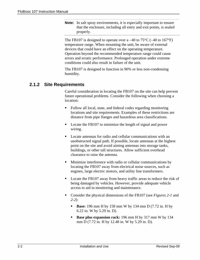
Note: In salt spray environments, it is especially important to ensure that the enclosure, including all entry and exit points, is sealed properly.
The FB107 is designed to operate over a −40 to 75°C (−40 to 167°F) temperature range. When mounting the unit, be aware of external devices that could have an effect on the operating temperature. Operation beyond the recommended temperature range could cause errors and erratic performance. Prolonged operation under extreme conditions could also result in failure of the unit.
The FB107 is designed to function in 90% or less non-condensing humidity.
2.1.2 Site Requirements Careful consideration in locating the FB107 on the site can help prevent future operational problems. Consider the following when choosing a location:
Follow all local, state, and federal codes regarding monitoring locations and site requirements. Examples of these restrictions are distance from pipe flanges and hazardous area classifications.
Locate the FB107 to minimize the length of signal and power wiring.
Locate antennas for radio and cellular communications with an unobstructed signal path. If possible, locate antennas at the highest point on the site and avoid aiming antennas into storage tanks, buildings, or other tall structures. Allow sufficient overhead clearance to raise the antenna.
Minimize interference with radio or cellular communications by locating the FB107 away from electrical noise sources, such as engines, large electric motors, and utility line transformers.
Locate the FB107 away from heavy traffic areas to reduce the risk of being damaged by vehicles. However, provide adequate vehicle access to aid in monitoring and maintenance.
Consider the physical dimensions of the FB107 (see Figures 2-1 and 2-2):
Base: 196 mm H by 158 mm W by 134 mm D (7.72 in. H by 6.22 in. W by 5.29 in. D).
Base plus expansion rack: 196 mm H by 317 mm W by 134 mm D (7.72 in. H by 12.48 in. W by 5.29 in. D).

FloBoss 107 Instruction Manual
4X Ø4.8 ][0.19134.45.29][
]6.22[158.0
][5.00127.0
][15.50.61
][
9.1
0.36
196.
17.
72[
]
][17
7.8
7.00
Figure 2-1. Side and Front View of FloBoss 107 Base Unit
Figure 2-2. FloBoss 107 and Expansion Rack
Revised Sep-09 Installation and Use 2-3

FloBoss 107 Instruction Manual
2.1.3 Compliance with Hazardous Area Standards The FB107 has approval for Class I Division 2 Groups A, B, C and D. Class, Division, and Group are defined as:
Class defines the general nature of the hazardous material in the surrounding atmosphere. Class I is for locations where flammable gases or vapors may be present in the air in quantities sufficient to produce explosive or ignitable mixtures.
Division defines the probability of hazardous material being present in an ignitable concentration in the surrounding atmosphere. Division 1 locations are presumed to be hazardous. Division 2 locations are areas where gas, dust, or vapors can exist under abnormal conditions.
Group defines the hazardous material in the surrounding atmosphere. Groups A to D are defined as follows:
o Group A – Atmosphere containing acetylene, gases or vapors of equivalent hazards.
o Group B – Atmosphere containing hydrogen, gases, or vapors of equivalent hazards.
o Group C – Atmosphere containing ethylene, gases, or vapors of equivalent hazards.
o Group D – Atmosphere containing propane, gases, or vapors of equivalent hazards.
For the FB107 to be approved for hazardous locations, it must be installed according to the National Electrical Code (NEC) Article 501, and any local code requirements, if applicable.
Caution When installing units in a hazardous area, make sure all installation components selected are labeled for use in such areas. Installation and maintenance must be performed only when the area is known to be non-hazardous. Installation in a hazardous area could result in personal injury or property damage.
2.1.4 Power Installation Requirements Typical sources of primary power for FB107 installations are dc voltage sources and solar power. Take care to route power away from hazardous areas, sensitive monitoring devices, and radio equipment. Local and company codes generally provide guidelines for power installations. Rigorously follow all local and National Electrical Code (NEC) requirements for power installations.
2-4 Installation and Use Revised Sep-09

FloBoss 107 Instruction Manual
Figure 2-3. Power Connection on Base Unit
Table 2-1. Power Connections
Label Function + Connection to Power Source + Connection to Power Source – Ground
The FB107 accepts input voltages from 8.0 volts to 30 volts at the PWR (IN+ / IN−) terminals on the CPU. The CPU terminal block accepts wires from size 16 to 24 AWG.
The AUX PWR IN terminal block accepts wires from size 12 to 22 AWG.
2.1.5 Grounding Installation Requirements Grounding wiring requirements for dc voltage sources equipment are governed by the National Electrical Code (NEC). When the equipment uses dc voltage sources, the grounding system must terminate at the service disconnect. All equipment grounding conductors must provide an uninterrupted electrical path to the service disconnect. The National Electrical Code Article 250-83 (1993), paragraph c,
defines the material and installation requirements for grounding electrodes.
The National Electrical Code Article 250-91 (1993), paragraph a, defines the material requirements for grounding electrode conductors.
The National Electrical Code Article 250-92 (1993), paragraph a, provides installation requirements for grounding electrode conductors.
The National Electrical Code Article 250-95 (1993) defines the size requirements for equipment grounding conductors.
Proper grounding of the FB107 helps to reduce the effects of electrical noise on the unit’s operation and protects against lightning. The FB107 provides lightning protection for built-in field wiring inputs and outputs. Install a surge protection device at the service disconnect on dc voltage source systems to protect against lightning and power surges for the installed equipment.
Revised Sep-09 Installation and Use 2-5

FloBoss 107 Instruction Manual
2-6 Installation and Use Revised Sep-09
All earth grounds must have an earth-to-ground rod or grid impedance of 25 ohms or less as measured with a ground system tester. The grounding conductor should have a resistance of 1 ohm or less between the FB107 enclosure ground and the earth ground rod or grid.
The recommended cable for I/O signal wiring is an insulated, shielded, twisted-pair. The twisted pair and the shielding minimize signal errors caused by EMI (electromagnetic interference), RFI (radio frequency interference), and transients.
Grounding the FB107 If your company has no specific grounding requirements, install the FB107 as a floating system (unconnected to ground). Otherwise, follow your company’s specific grounding practices. However, if you are making a connection between a grounded device and the FB107’s EIA-232 (RS-232) port, ground the FB107’s power input by connecting the PWR– to ground. The grounding installation method for the FB107 depends on whether the pipeline has cathodic protection. On pipelines with cathodic protection, electrically isolate the FB107 from the pipeline.
Use insulating flanges upstream and downstream on the meter run to achieve electrical isolation. In this case, you can place the FB107 in an enclosure which is either flange-mounted or saddle-clamp mounted directly on the meter run and grounded with a ground rod or grid system.
On pipelines without cathodic protection, the pipeline itself may provide an adequate earth ground. Place the FB107 in an enclosure mounted directly on the meter run. Test with a ground system tester to make sure the pipeline-to-earth impedance is less than 2 ohms. If the pipeline provides an adequate ground, you may not need to install a separate ground rod or grid system. All grounding should terminate at a single point.
If the pipeline to earth impedance is greater than 2 ohms, electrically isolate the FB107 installation and install a ground rod or grid grounding system.
2.1.6 I/O Wiring Requirements I/O wiring requirements are site- and application-dependent. Local, state, and NEC requirements determine the I/O wiring installation methods. Direct buried cable, conduit and cable, or overhead cable are all options for I/O wiring installations.
Shielded, twisted-pair cable is recommended for I/O signal wiring. The twisted-pair minimizes signal errors caused by Electro-Magnetic Interference (EMI), Radio Frequency Interference (RFI), and transients. Use insulated, shielded, twisted-pair wiring when using Multi-Variable Sensor (MVS) signal lines. The terminal block accepts wires up to size 16 to 24 AWG.

FloBoss 107 Instruction Manual
2.2 Installing the FloBoss 107 and Expansion Rack This section details how to install the FB107 base unit and the expansion rack.
Caution To avoid circuit damage when working inside the unit, use appropriate electrostatic discharge precautions (such as wearing a grounded wrist strap).
When working on units located in a hazardous area (where explosive gases may be present), make sure the area is in a non-hazardous state before performing procedures. Performing these procedures in a hazardous area could result in personal injury or property damage.
2.2.1 Required Tools Use the following tools to perform installation and maintenance procedures on the FB107. For tools required for installation or maintenance of accessories, refer to the ROC/FloBoss Accessories Instruction Manual (Form A4637).
Philips screwdriver, size 0.
Flat blade screwdriver, size 2.5 mm (0.1 inch).
Flat blade screwdriver, large.
2.2.2 Installing the FloBoss 107 without an Expansion Rack To install the FB107 base unit without the expansion rack:
1. Using the four holes on the FB107 base unit, mark the points at which the base unit should attach to the wall (refer to Figure 2-1).
2. Drill four holes into the wall.
3. Position the FB107 to line up with the mounting holes you drilled.
4. Insert four #8 screws through the FB107 base unit and screw them into the wall or the mounting plate. Do not over tighten.
Note: Depending on your installation, you may require wall anchors or longer screws than are supplied.
Using an Adapter Plate
To simplify installation, you can purchase an optional metal adapter plate (product number FS1ADP-1) for the FB107 base unit (see Figure 2-3. Adapter Plate (FB107 Base Unit). After you secure the adapter plate to its location (using #8 mounting screws), the FB107 base unit attaches directly to the adapter plate.
Revised Sep-09 Installation and Use 2-7

FloBoss 107 Instruction Manual
8.88
[]
225.
6
[ 8.4
721
5.1 ]
0.246.1
[]
7.00
177.
8[
]
5.00127.0[ ]
165.16.50[ ]
][7.68195.1
Attachment posts
Plate mounting holes
Figure 2-3. Adapter Plate (FB107 Base Unit)
To install the FB107 base unit to the FS1ADP-1 adapter plate:
1. Place the unpowered base unit over the attachment posts.
2. Secure the base unit to the adapter plate using the four provided #8 mounting screws. Torque screws to 10-12 in-lbs.
2.2.3 Installing the FloBoss with an Expansion Rack The expansion rack has connectors for the I/O, MVS, and application modules.
Do not remove the backplane from the housing. The backplane does not contain any field-serviceable parts. If the backplane requires maintenance, please contact your local sales representative.
Notes: The alignment of the connectors between the base unit and
expansion rack is critical.
The optional adapter plate (product FS1ADP-2) greatly simplifies the installation process for an expansion rack.
To install the FB107 with the expansion rack:
1. Remove power from the FB107.
2. Align and gently press together the left edge of the expansion rack with the right edge of the base unit. Ensure that the connectors fit together.
3. Using the four holes on the expansion rack, mark the points at which the expansion rack should attach to the wall. Refer to Figure 2-2.
4. Detach the expansion rack from the base unit.
2-8 Installation and Use Revised Sep-09

FloBoss 107 Instruction Manual
5. Drill four holes into the wall.
6. Reattach the expansion rack to the base unit, ensuring that the holes in the expansion rack align with the mounting holes you drilled.
7. Insert the screws through the expansion rack into the wall. Do not over tighten.
8. Return power to the FB107.
Note: Depending on your installation, you may require wall anchors or longer screws than are supplied.
Using an Adapter Plate
To simplify installation, you can purchase an optional metal adapter plate (product number FS1ADP-2) for the FB107 base unit and expansion rack. After you secure the adapter plate to its location (using #8 mounting screws), the base unit and expansion rack attach directly to the adapter plate.
31.81.25[ ]
5.00127.0[ ]
127.05.00[ ]
317.512.50[ ]
11.12[282.5
]
3.40
86.4
[]
0.389.5
[]
7.00
[177.
8 ]
][ 7
.75
196.
8
Attachment posts
Plate mounting holes
Retaining clips
Figure 2-4. Adapter Plate (FB107 Expansion Rack)
To install the base unit and expansion rack to the FS1ADP-2 adapter plate:
1. Place the unpowered base unit on the left side of the adapter plate so that the attachment posts touch the right-most inside of the plastic housing.
2. Slide the base unit to the right.
Note: You should feel the retaining clips attach to the back of the base unit and the attachment posts should appear in the right-most holes on the base unit’s plastic housing.
3. Secure the base unit to the adapter plate by placing two #8 mounting screws in the upper and lower right-most holes in the base unit. Torque screws to 10-12 in-lbs.
Revised Sep-09 Installation and Use 2-9
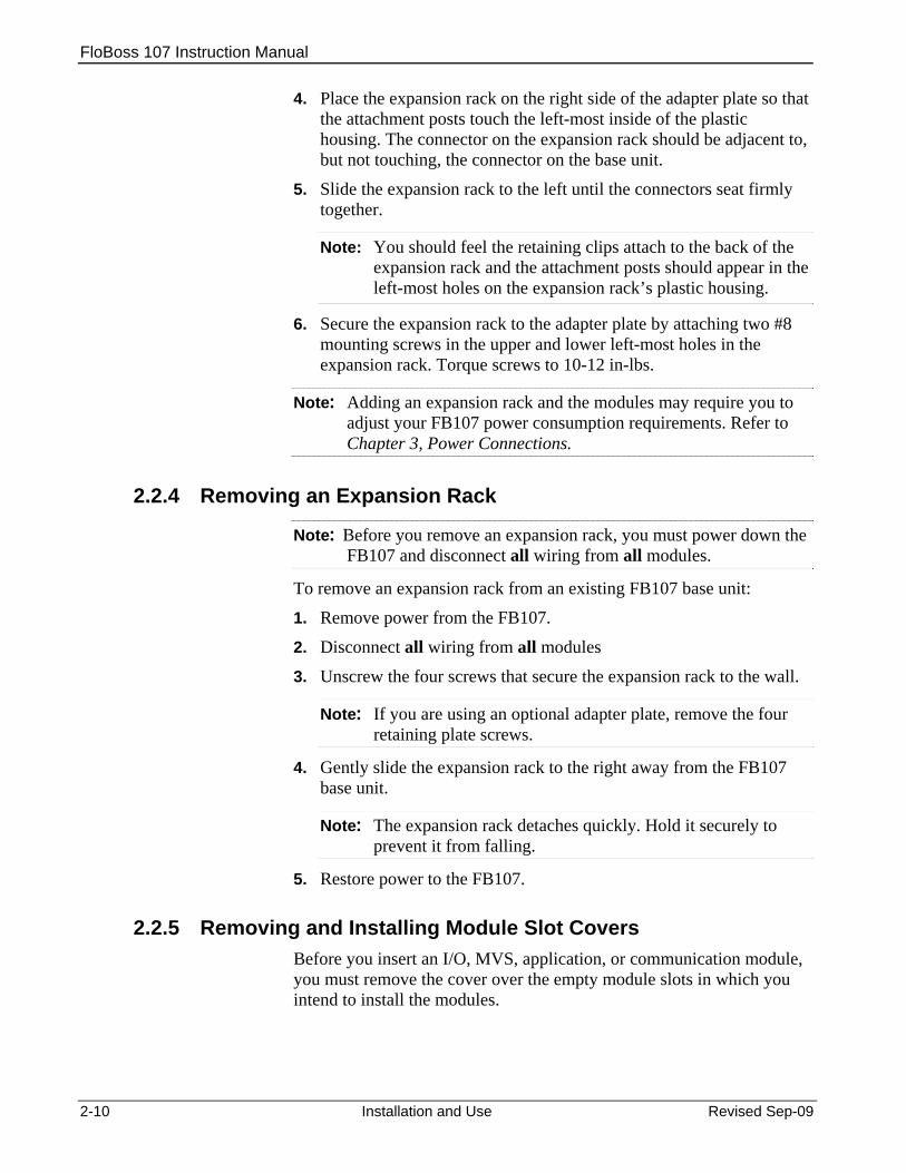
FloBoss 107 Instruction Manual
2-10 Installation and Use Revised Sep-09
4. Place the expansion rack on the right side of the adapter plate so that the attachment posts touch the left-most inside of the plastic housing. The connector on the expansion rack should be adjacent to, but not touching, the connector on the base unit.
5. Slide the expansion rack to the left until the connectors seat firmly together.
Note: You should feel the retaining clips attach to the back of the expansion rack and the attachment posts should appear in the left-most holes on the expansion rack’s plastic housing.
6. Secure the expansion rack to the adapter plate by attaching two #8 mounting screws in the upper and lower left-most holes in the expansion rack. Torque screws to 10-12 in-lbs.
Note: Adding an expansion rack and the modules may require you to adjust your FB107 power consumption requirements. Refer to Chapter 3, Power Connections.
2.2.4 Removing an Expansion Rack
Note: Before you remove an expansion rack, you must power down the FB107 and disconnect all wiring from all modules.
To remove an expansion rack from an existing FB107 base unit:
1. Remove power from the FB107.
2. Disconnect all wiring from all modules
3. Unscrew the four screws that secure the expansion rack to the wall.
Note: If you are using an optional adapter plate, remove the four retaining plate screws.
4. Gently slide the expansion rack to the right away from the FB107 base unit.
Note: The expansion rack detaches quickly. Hold it securely to prevent it from falling.
5. Restore power to the FB107.
2.2.5 Removing and Installing Module Slot Covers Before you insert an I/O, MVS, application, or communication module, you must remove the cover over the empty module slots in which you intend to install the modules.

FloBoss 107 Instruction Manual
Caution To avoid circuit damage when working inside the unit, use appropriate electrostatic discharge precautions (such as wearing a grounded wrist strap).
When working on units located in a hazardous area (where explosive gases may be present), make sure the area is in a non-hazardous state before performing procedures. Performing these procedures in a hazardous area could result in personal injury or property damage.
To remove a module slot cover: 1. Press the tab on the right side of the slot cover in.
2. Lift up and remove the slot cover.
Note: If you remove a module for an extended period, install a slot cover over the empty module slot to prevent dust and other matter from getting into the FB107.
To install a module slot cover: 1. Place the slot cover over the empty slot. The tabs on the left side of
the slot cover help align the cover in the empty slot.
2. Lower the slot cover until it clicks in place.
2.2.6 Removing and Installing Wire Channel Covers Install the wire channel covers over the wiring channels once the wiring of the terminal blocks is complete. Wire channel covers are located on the front of the FB107.
To remove a wire channel cover: 1. Grasp the wire channel cover at either the right or left edge.
2. Firmly pull the cover up from the wire channel.
To replace a wire channel cover: 1. Align the wire channel cover over the wire channel, ensuring
unobstructed wire access.
2. Press the wire channel cover down into place until it snaps.
2.3 Memory Backup Battery A super capacitor (“super-cap”) and a coin type battery work together to provide backup power for the static RAM and the real-time clock. This helps to ensure retention of short and longer-term data, configuration, and operational integrity when the FB107 is not in service or is in storage.
Revised Sep-09 Installation and Use 2-11

FloBoss 107 Instruction Manual
Note: You can replace the battery with a standard coin type lithium model CR2032 (DL2032).
Caution To avoid circuit damage when working inside the unit, use appropriate electrostatic discharge precautions (such as wearing a grounded wrist strap).
When working on units located in a hazardous area (where explosive gases may be present), make sure the area is in a non-hazardous state before performing procedures. Performing these procedures in a hazardous area could result in personal injury or property damage.
2.3.1 Removing and Installing the Battery To remove the battery on the backplane:
1. Remove power from the FB107.
Memory Backup
Figure 2-5. Memory Backup Cap
2. Slide the Memory Backup cover to the left.
3. Remove the battery by gently prying the battery from its terminals.
4. Replace the battery by placing the battery positive-side up and gently pressing it into place.
5. Slide the Memory Backup cover back over the battery.
6. Restore power to the FB107.
2-12 Installation and Use Revised Sep-09
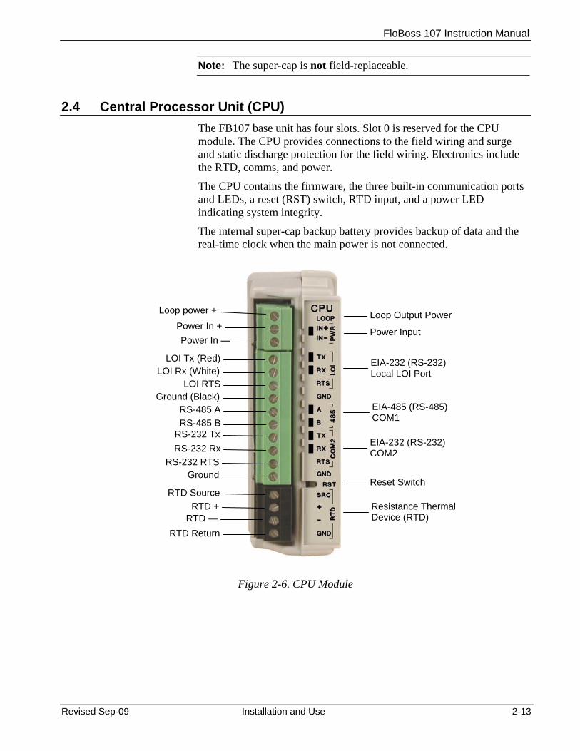
FloBoss 107 Instruction Manual
Note: The super-cap is not field-replaceable.
2.4 Central Processor Unit (CPU) The FB107 base unit has four slots. Slot 0 is reserved for the CPU module. The CPU provides connections to the field wiring and surge and static discharge protection for the field wiring. Electronics include the RTD, comms, and power.
The CPU contains the firmware, the three built-in communication ports and LEDs, a reset (RST) switch, RTD input, and a power LED indicating system integrity.
The internal super-cap backup battery provides backup of data and the real-time clock when the main power is not connected.
Loop power + Loop Output Power
Power In —Power In + Power Input
RS-485 B
GroundRS-232 RTS
RS-232 RxRS-232 Tx
RS-485 AGround (Black)
LOI RTSLOI Rx (White)
LOI Tx (Red) EIA-232 (RS-232) Local LOI Port
EIA-485 (RS-485) COM1
EIA-232 (RS-232) COM2
Reset Switch
RTD +
RTD ReturnRTD —
RTD SourceResistance Thermal Device (RTD)
Figure 2-6. CPU Module
Revised Sep-09 Installation and Use 2-13
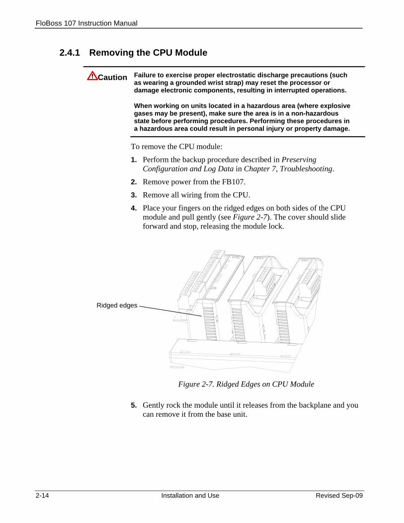
FloBoss 107 Instruction Manual
2.4.1 Removing the CPU Module
Caution Failure to exercise proper electrostatic discharge precautions (such as wearing a grounded wrist strap) may reset the processor or damage electronic components, resulting in interrupted operations.
When working on units located in a hazardous area (where explosive gases may be present), make sure the area is in a non-hazardous state before performing procedures. Performing these procedures in a hazardous area could result in personal injury or property damage.
To remove the CPU module:
1. Perform the backup procedure described in Preserving Configuration and Log Data in Chapter 7, Troubleshooting.
2. Remove power from the FB107.
3. Remove all wiring from the CPU.
4. Place your fingers on the ridged edges on both sides of the CPU module and pull gently (see Figure 2-7). The cover should slide forward and stop, releasing the module lock.
Ridged edges
Figure 2-7. Ridged Edges on CPU Module
5. Gently rock the module until it releases from the backplane and you can remove it from the base unit.
2-14 Installation and Use Revised Sep-09

FloBoss 107 Instruction Manual
2.4.2 Installing the CPU Module
Caution Failure to exercise proper electrostatic discharge precautions (such as wearing a grounded wrist strap) may reset the processor or damage electronic components, resulting in interrupted operations.
When working on units located in a hazardous area (where explosive gases may be present), make sure the area is in a non-hazardous state before performing procedures. Performing these procedures in a hazardous area could result in personal injury or property damage.
To install the CPU module: 1. Remove power from the FB107.
2. Slide the CPU module into slot 0.
Note: The CPU wire terminals face to the left. A tab on the module case prevents you from installing the module incorrectly.
3. Press the CPU firmly into the slot. The connectors at the back of the CPU module fit securely into the connectors on the backplane.
4. Wire the CPU (see Figure 2-6).
5. Review Restarting and Reconfiguring the FB107 in Chapter 7, Troubleshooting.
6. Return power to the FB107.
2.4.3 Resetting the CPU The FB107 CPU provides a reset (RST) switch (see Figure 2-6). Use it to restore the FB107 to factory default settings. See Resetting the FB107 in Chapter 7, Troubleshooting for specific instructions.
2.5 License Keys License keys with valid license codes grant access to applications or allow optional firmware functionality to execute. A license key may also be required before you can run the application. Examples of licensed applications may include flow or properties calculations and various user programs. You can configure these applications using ROCLINK 800’s License Key Administrator function (Utilities > License Key Administrator).
If you remove a license key after enabling an application, the firmware disables the task from running. This prevents unauthorized execution of protected applications.
Note: You must remove power and re-power the FB107 when you install or remove a license key.
Revised Sep-09 Installation and Use 2-15
FloBoss 107 Instruction Manual
2.6 Startup and Operation Before starting the FB107, perform the following checks to ensure the unit is properly installed. Check the field wiring for proper installation. Make sure the input power has the correct polarity. Make sure that the CPU, I/O, MVS, application, and communication
modules are seated in the backplane. Make sure the input power is fused at the power source. Plug the
input power either into the AUX PWR IN on the base unit or into the connector labeled PWR+ / PWR − on the CPU module.
2.6.1 Startup Before you apply power to the FB107, assess the power requirements (including the base unit, expansion rack, and any installed modules and peripheral devices) that comprise the total configuration for your FB107. Refer to Determining Power Consumption in Chapter 3, Power Connections.
Apply power to the FB107. The power input PWR+ LED indicator should light green to indicate that the applied voltage is correct and a valid operation is active.
After the start-up diagnostics (RAM and other internal checks) complete, you should be able to log in to the FB107, which indicates the FB107 completed a valid reset sequence. If you cannot log on to the FB107, refer to Chapter 7, Troubleshooting, for possible causes.
Caution Check the input power polarity before connecting power to the FB107. Incorrect polarity can damage the FB107.
When working on units located in a hazardous area (where explosive gases may be present), make sure the area is in a non-hazardous state before performing procedures. Performing these procedures in a hazardous area could result in personal injury or property damage.
2.6.2 Operation Once startup is successful, it is necessary to configure the FB107 to meet the requirements of the application. Refer to the ROCLINK 800 Configuration Software User Manual (for FloBoss 107) (Form A6217) for procedures on configuring the FB107 and calibrating its I/O. Once you configure and calibrate the FB107, you can place it in operation.
During operation, you can monitor the FB107 to view or retrieve current and historical data either locally or remotely. You accomplish local monitoring using ROCLINK 800 on a PC connected through the LOI
2-16 Installation and Use Revised Sep-09

FloBoss 107 Instruction Manual
Revised Sep-09 Installation and Use 2-17
port. You accomplish remote monitoring by using ROCLINK 800 connected through the COM1 through COM3 ports.
The FB107 has a number of software settings (parameters) which you must configure (using ROCLINK 800 on a PC) before the unit is calibrated and placed into operation. Normally, the PC is connected to the LOI port of the FB107 to transfer configuration data into the FB107, although you can perform much of the configuration off-line and later load it into the FB107.
The FB107 firmware provides default values for all parameters. If the default values are acceptable for your application, leave the device as it was delivered from the factory.

FloBoss 107 Instruction Manual
2-18 Installation and Use Revised Sep-09
[This page is intentionally left blank]
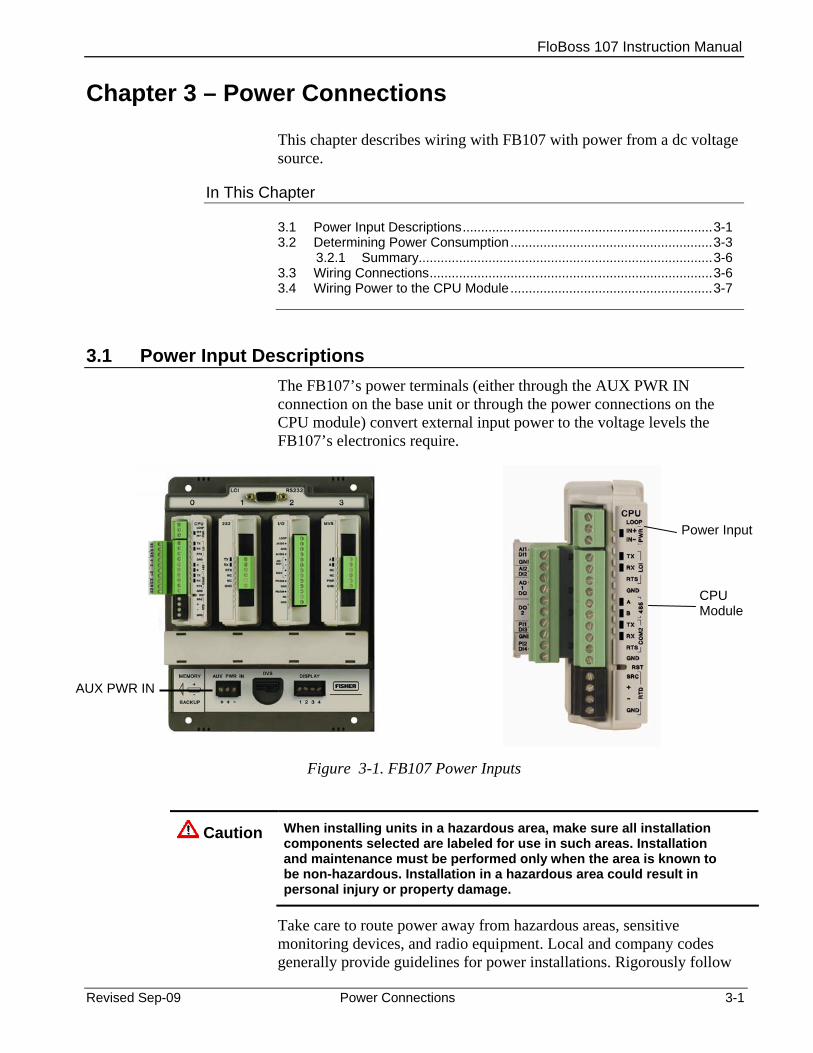
FloBoss 107 Instruction Manual
Chapter 3 – Power Connections
This chapter describes wiring with FB107 with power from a dc voltage source.
In This Chapter
3.1 Power Input Descriptions....................................................................3-1 3.2 Determining Power Consumption.......................................................3-3
3.2.1 Summary................................................................................3-6 3.3 Wiring Connections.............................................................................3-6 3.4 Wiring Power to the CPU Module.......................................................3-7
3.1 Power Input Descriptions The FB107’s power terminals (either through the AUX PWR IN connection on the base unit or through the power connections on the CPU module) convert external input power to the voltage levels the FB107’s electronics require.
Power Input
CPU Module
AUX PWR IN
Figure 3-1. FB107 Power Inputs
Caution When installing units in a hazardous area, make sure all installation components selected are labeled for use in such areas. Installation and maintenance must be performed only when the area is known to be non-hazardous. Installation in a hazardous area could result in personal injury or property damage.
Take care to route power away from hazardous areas, sensitive monitoring devices, and radio equipment. Local and company codes generally provide guidelines for power installations. Rigorously follow
Revised Sep-09 Power Connections 3-1
FloBoss 107 Instruction Manual
3-2 Power Connections Revised Sep-09
all local and National Electrical Code (NEC) requirements for power installations.
Power Requirements
A dc voltage source is the typical source of primary power for FB107 installations. The FB107 accepts input voltages from 8.0 volts to 30.0 volts either at the AUX PWR IN connection on the base unit or at the PWR (IN+ / IN−) terminals on the CPU. The AUX PWR IN terminal block accepts wires from size 12 to 22 AWG.
The power consumption of an FB107 and the attached expansion racks determines the current requirements for the external power supply.
The CPU module’s power input has a removable terminal block for wiring and servicing. The terminal blocks can accept size 16 to 24 AWG (American Wire Gauge).
Note: Isolation occurs between the CPU and the field logic.
Using ROCLINK 800, you can configure the I/O on the CPU module to set the loop output power to 10 volts dc or 24 volts dc using ROCLINK 800. The I/O module only supports 24 volts dc loop output power.
Note: The CPU I/O assembly uses the CPU’s loop power output and ground connections.
The intent of the loop output power is to power devices that require 24 volts dc to ground, allowing the external device to send the FB107 a 4 to 20 mA signal based on pressure, temperature, level, and such.
The 10-volt loop output power is intended for low power transmitters. The loop current is designed to deliver 80 mA to power two field devices that connect back to the two analog inputs.
Note: If the input voltage is greater than the 10-volt loop, then the loop voltage equals the input voltage. For example, if the PWR IN is 14 volts dc and you select a 10-volt loop, the loop output equals 14 volts dc.
You can use current analog inputs of 4 to 20 mA when the 250-ohm resistor is selected in the AI configuration using ROCLINK 800.
Table 3-1. Input Terminal Block Connections Terminal Blocks Definition Volts DC PWR (IN + / IN –) Accepts up to 28 Volts dc nominal from an AC/DC converter
or other 28 volts dc supply. 8 to 30 Volts dc
LOOP and GND Supplies 10 Volts dc or 24 Volts dc source voltage to external field devices. Current limit protected.
10 Volts dc or 24 Volts dc

FloBoss 107 Instruction Manual
Revised Sep-09 Power Connections 3-3
3.2 Determining Power Consumption Use Table 3-1 to identify and Table 3-2 to calculate the power requirements for the configuration of your FB107. If the power input is not sufficient, you must either provide an alternative power supply for external devices or reduce power demands. See Table 3-3 for an example of a completed power consumption worksheet.
Note: The worksheet shown in Table 3-2 is available to registered users as a Microsoft Excel® spreadsheet on the Remote Automation Solutions SupportNet™ website. Access www.EmersonProcess.com/Remote/Support/Support_login.html and look for FB107_Power_Wksht.xls under Downloads. Download the spreadsheet to calculate—and manage—variations on your particular power requirements.
Table 3-1. Estimated Power Consumption by Module
Valid Slots
Module Description Base Idle (No Load)
Max Active (Full Load)
Loading Factor
Module Power2
in mW 0 CPU Non-Isolated 360 360 100% 360 0 CPU Non-Isolated with I/O 396 476 100% 476 0 CPU Isolated 540 540 100% 540 0 CPU Isolated with I/O 576 656 100% 656
1,2 RS-232 Module 21 50 100% 50 1,2 RS-485 Module 27 35 100% 35 1,2 Enhanced Comm Module 450 610 100% 610 1,2 Dial-up Modem Module 1 2 100% 2
1 through 71 6-Point I/O Module 180 260 100% 260 1 through 71 DO Relay Module 180 270 100% 270 1 through 71 8-Point AI/DI Module 145 3900 100% 3900 1 through 71 6-Channel AO/DO Module 320 2900 100% 2900 1 through 71 3-Channel RTD Module 220 225 100% 225 1 through 7 HART Module 210 410 100% 410 1 through 7 MVS Interface Module 150 200 100% 200 1 through 7 APP 485 Application Module 150 160 100% 160
1Valid for slot 7 only if a Comm module is installed in slot 1 2Represents Base (Loop loading x Loading Factor)

FloBoss 107 Instruction Manual
3-4 Power Connections Revised Sep-09
Table 3-2. Power Consumption Worksheet Power1
Total Power System Power (mW)
Field Power (mW) Voltage2
Input Voltage (V dc) Field Voltage (V dc)
Total Voltage Current3
System Current mA Communications mA (Average)
Total Current mA on Power System Miscellaneous4
Battery Voltage Battery Capacity Amp/Hour
Depth of Discharge Available Hours
Days of Autonomy 1System Power represents the base or idle load; Field Power represents the active load; Total Power is the sum of the two values, representing the maximum of all modules at all times. 2Voltage indicates 12 V dc or 24 V dc Power Input module. 3Current (calculated as Total Power / Input Voltage) represents the system current as well as any added external current through communications devices. 4Miscellaneous identifies several components: Battery Voltage: a given value from the manufacturer Battery Capacity Amp/Hr: a given value from the manufacturer Depth of Discharge: A percentage of battery power used. Available Hours: The number of hours the unit can be powered without external charging of the
power system. Days of Autonomy: the number of days the device can perform without external power, given
the estimated power requirements.

FloBoss 107 Instruction Manual
For example, let’s suppose the following module configuration for an eight-slot FB107:
Valid Slots
Module Description
Base Idle(No Load)
Max Active (Full Load)
Add’l Load
Loading Factor
Module Power in mW
0 CPU Isolated with I/O 576 656 80 100% 656 1 Enhanced Comm Module 450 610 160 20% 482 2 8-Point AI/DI Module 145 3900 3755 100% 3900 3 6-Point I/O Module 180 260 80 100% 260 4 6-Point I/O Module 180 260 80 100% 260 5 DO Relay Module 180 270 90 100% 270 6 HART Module 210 410 200 10% 230 7 MVS Interface Module 150 200 50 100% 200
Totals 2071 6566 6258 The resulting worksheet would resemble:
Revised Sep-09 Power Connections 3-5
Power
Total Power 6258System Power (mW) 2071
Field Power (mW) 4187 Voltage
Input Voltage (V dc) 12.0 Field Voltage (V dc) 24
Current System Current mA 521.5
Communications mA (Average) 300.0 Total Current mA on Power System 821.5
Miscellaneous Battery Voltage 12.0
Battery Capacity Amp/Hour 72.0 Depth of Discharge 20%
Available Hours 70.1 Days of Autonomy 2.92
A
B
C
E
D
F
G
A Calculated by adding base idle (no load) values for all chosen modules B Calculated by adding System Power and Field Power values (2071 + 4187) C Calculated by subtracting System Power value from Total Power value (6258 – 2071) D Calculated by dividing Total Power by Input Voltage (6258/12) E Entered value from manufacturer’s specifications F Calculated by adding System Current and Communications Current (521.5 + 300) G Value provided by battery manufacturer
FloBoss 107 Instruction Manual
3.2.1 Summary Using the worksheet, you can determine the day-to-day power requirements for your intended system as well as how much battery power you may require to maintain your system in the absence of external power. By downloading the Excel spreadsheet from SupportNet, you can then adjust your expectations and requirements to meet your FB107 power needs.
3.3 Wiring Connections This section describes how to connect the FB107 to power, I/O devices, and communication devices. Use the recommendations and procedures described in this section to avoid damage to equipment.
Note: Check the input power polarity before you apply the power.
The external connections or field terminals are located on the CPU or optional modules. The terminal block accepts wires up to size 16 to 24 AWG.
Caution Always turn off the power to the FB107 before you attempt any type of wiring. Wiring powered equipment could result in personal injury or property damage.
To avoid circuit damage when working inside the unit, use appropriate electrostatic discharge precautions, such as wearing a grounded wrist strap.
I/O wiring requirements are site- and application-dependent. Local, state, or NEC requirements determine the I/O wiring installation methods. Direct burial cable, conduit and cable, or overhead cables are options for I/O wiring installations.
Caution Failure to exercise proper electrostatic discharge precautions, such as wearing a grounded wrist strap may reset the processor or damage electronic components, resulting in interrupted operations.
To connect the wire to the removable block compression terminals:
1. Strip ¼ inch of insulation from the wire.
2. Insert the bare end into the clamp beneath the termination screw.
3. Tighten the screw, taking care not to over-torque it.
Expose a minimum of bare wire to prevent short circuits. Allow some slack when making connections to prevent strain.
Note: Twisted-pair cable is recommended for I/O signal wiring.
3-6 Power Connections Revised Sep-09

FloBoss 107 Instruction Manual
3.4 Wiring Power to the CPU Module Typically, you would use the AUX PWR IN connection on the FB107 base unit to power the FB107. Alternately, you can wire power directly into the CPU module.
Power In – Power In +
Loop Power + Output
Figure 3-2. Power Wiring, CPU Module
The CPU module connectors use compression terminals. The input power termination (IN+ / IN−) uses a removable connector and accommodates wiring size 16 to 24 AWG. Refer to Section 3.3, Wiring Connections.
The FB107 accepts input voltages from 8.0 to 30.0 volts at the PWR IN+ / IN− input power terminals
Labels on the CPU (see Figure 3-2) identify the IN+ terminal for positive power connection (8.0 to 30.0 volts power) and the IN− terminal for negative power connection (Battery Common).
Note: Follow good wiring practices when sizing, routing, and connecting power wiring. All wiring must conform to state, local, and NEC codes.
Revised Sep-09 Power Connections 3-7

FloBoss 107 Instruction Manual
3-8 Power Connections Revised Sep-09
[This page is intentionally left blank]
FloBoss 107 Instruction Manual
Revised Sep-09 Inputs and Outputs 4-1
Chapter 4 – Inputs and Outputs
This chapter describes the input/output (I/O) termination points available on the CPU module’s optional I/O assembly and the I/O modules. I/O points provide additional inputs and outputs for implementing expanded monitoring and control applications. This chapter also describes the resistance thermal device (RTD) input on the CPU.
Note: You can place an I/O module in any slot (1 through 7) in the FB107. When you install a non-I/O module in slot 1, you can install an I/O module in slot 7 of the expansion rack.
In This Chapter
4.1 I/O Description ....................................................................................4-1 4.2 Installing a Module..............................................................................4-4 4.3 Removing a Module............................................................................4-6 4.4 Wiring a Module..................................................................................4-6 4.5 Selecting the Type of I/O ....................................................................4-7 4.6 Analog Inputs (AI) ...............................................................................4-9
4.6.1 Wiring the Analog Inputs........................................................4-9 4.7 8-Point Analog Input/Digital Input (AI/DI) Module.............................4-11
4.7.1 Wiring the 8-Point AI/DI .......................................................4-11 4.8 Analog Outputs (AO) ........................................................................4-13
4.8.1 Wiring the Analog Outputs...................................................4-13 4.9 Discrete Inputs (DI) ...........................................................................4-14
4.9.1 Wiring the Discrete Inputs....................................................4-15 4.10 Discrete Outputs (DO) ......................................................................4-15
4.10.1 Wiring the Discrete Outputs.................................................4-16 4.11 Discrete Outputs Relay (DOR) Module ............................................4-17
4.11.1 Wiring the Discrete Output Relays ......................................4-18 4.12 Pulse Inputs (PI) ...............................................................................4-19
4.12.1 Wiring the Pulse Inputs........................................................4-19 4.13 Application (APP 485) Module..........................................................4-20
4.13.1 Wiring the Application Module .............................................4-20 4.14 Resistance Temperature Detector (RTD) Input................................4-21
4.14.1 Wiring the RTD Input ...........................................................4-22 4.15 6-Point AO/DO Module .....................................................................4-23
4.15.1 Wiring the 6-Point AO/DO Module.......................................4-23 4.16 HART® Module..................................................................................4-24
4.16.1 Wiring the HART Module .....................................................4-25 4.17 Resistance Temperature Detector (RTD) Module ............................4-26
4.17.1 Wiring the RTD Module .......................................................4-26 4.18 Related Technical Specifications......................................................4-27
4.1 I/O Description The I/O options use the microprocessor for monitoring, control, and acquisition of data from external devices connected to the I/O channels.

FloBoss 107 Instruction Manual
4-2 Inputs and Outputs Revised Sep-09
The I/O channels have a removable plug-in terminal block for field wiring. You can order the expanded 6-point I/O as an: I/O assembly that mounts directly on the CPU module. I/O modules that mount in the I/O slots.
Both ways provide configuration terminations for six points of expansion I/O and both provide the same selections for I/O.
The six points of I/O consist of: Two analog inputs (AI) or discrete inputs (DI). One analog output (AO) or discrete output (DO). One discrete output (DO). Two pulse inputs (PI) or discrete inputs (DI).
Using ROCLINK 800, you can select and configure five of the six I/O points. Use ROCLINK 800’s I/O Setup screen to select the inputs and outputs.
You can add an expansion rack to the FB107 to increase I/O by four slots for a total of six slots of I/O. The FB107 can support up to six I/O modules.
You can install I/O modules in slots 1 through 3 on the FB107 base unit and in slots 4 through 6 on the expansion rack.
I/O support for the FB107 includes:
Analog inputs (AI) that provide the ability to monitor various analog field values.
Discrete inputs (DI) and pulse inputs (PI) that provide the ability to monitor various discrete and pulse input field values.
Analog outputs (AO) and discrete outputs (DO) that provide the ability to manage various control devices.
RTD input provides the ability to monitor various analog temperature field values.
Each module rests in a module slot at the front of the FB107 base unit or expansion rack. The CPU I/O assembly attaches to the CPU module.
The I/O modules acquire power from the backplane. Each module has a dc/dc converter that provides logic, control, and field power as required. The CPU I/O assembly acquires logic, control, and field power from the CPU module.
The FB107 has eliminated the need for fuses on the loop output and analog output through the extensive use of current-limited short-circuit protection.
Figure 4-1 and Table 4-1 detail the I/O terminations on the I/O module. Figure 4-2 and Table 4-2 detail the I/O terminations on the CPU module’s optional I/O assembly.
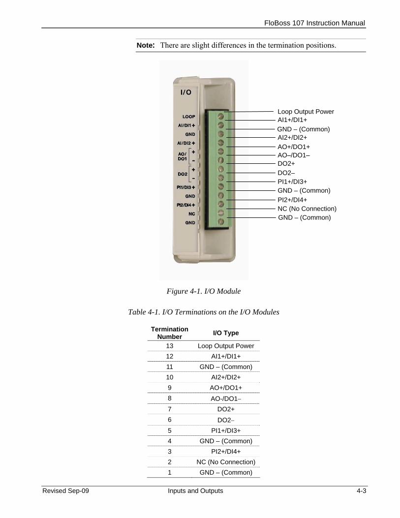
FloBoss 107 Instruction Manual
Note: There are slight differences in the termination positions.
Figure 4-1. I/O Module
Table 4-1. I/O Terminations on the I/O Modules
Revised Sep-09 Inputs and Outputs 4-3
Termination
Number I/O Type
13 Loop Output Power 12 AI1+/DI1+ 11 GND – (Common) 10 AI2+/DI2+ 9 AO+/DO1+ 8 AO-/DO1− 7 DO2+ 6 DO2− 5 PI1+/DI3+ 4 GND – (Common) 3 PI2+/DI4+ 2 NC (No Connection) 1 GND – (Common)
GND – (Common) NC (No Connection) PI2+/DI4+ GND – (Common) PI1+/DI3+ DO2–
AO+/DO1+ AO–/DO1– DO2+
Loop Output Power
GND – (Common) AI2+/DI2+
AI1+/DI1+

FloBoss 107 Instruction Manual
AI1+/DI1+
GND – (Common) AI2+/DI2+
AO+/DO1+AO–/DO1–
DO2+ DO2–
PI1+/DI3+GND – (Common)
PI2+/DI4+
Figure 4-2. CPU Module’s Optional I/O Assembly
Table 4-2. I/O Terminations on the CPU Module’s Optional I/O Assembly
Termination Number I/O Type
10 AI1+/DI1+ 9 GND – (Common) 8 AI2+/DI2+ 7 AO+/DO1+ 6 AO-/DO1− 5 DO2+ 4 DO2− 3 PI1+/DI3+ 2 GND – (Common) 1 PI2+/DI4+
4.2 Installing a Module All I/O modules for the FB107 are designed for ease of installation and removal. They contain no user-serviceable components.
4-4 Inputs and Outputs Revised Sep-09
FloBoss 107 Instruction Manual
Note: A tab on the module’s case prevents you from installing the module incorrectly.
To install an I/O module in either the base unit or the expansion rack:
1. Remove power from the FB107.
2. Remove the wire channel cover.
3. Perform one of the following:
If there is a module currently in the slot, remove that module. Refer to Section 4.3, Removing a Module.
If the slot is currently empty, remove the slot cover.
4. Ensure that the module cover (the piece with ridged edges) is closed against the body of the module. This enables the locking mechanism to secure the module in the slot.
5. Insert the module in the slot on the base unit or expansion rack. Ensure that the module is installed facing the correct direction. Gently slide the module into place until it contacts properly with the connectors on the backplane.
Note: If the module stops and does not go any further, do not force the module. Remove the module and see if the pins are bent. If the pins are bent, gently straighten the pins and re-insert the module. The back of the module must connect fully with the connectors on the backplane.
6. Wire the I/O module. Refer to Section 4.4, Wiring a Module.
7. Replace the wire channel cover.
Caution Never connect the sheath surrounding shielded wiring to a signal ground terminal or to the common terminal of an I/O module or CPU I/O assembly. Doing so makes the I/O module susceptible to static discharge, which can permanently damage the I/O. Connect the shielded wiring sheath only to a suitable earth ground.
8. Return power to the FB107.
9. Connect to ROCLINK 800 and log in.
10. Configure the I/O point.
Note: You must perform a power re-start to enable the ROCLINK 800 software to identify the module.
Revised Sep-09 Inputs and Outputs 4-5

FloBoss 107 Instruction Manual
4.3 Removing a Module To remove an I/O module:
1. Remove power from the FB107.
2. Remove the wiring (or the removable terminal blocks) from the module.
3. Place your fingers on the ridged edges on both sides of the module and pull out gently (see Figure 4-3). The cover should slide forward and stop, releasing the module lock.
Figure 4-3. Ridged Edges on Modules
Ridged edges
4. Gently rock the module until it releases from the backplane and you can remove it from the base unit or expansion rack.
Note: Once you remove a module, always be sure to replace its cover. This protects the module slot from dust and prevents damage to the cover’s locking mechanism.
4.4 Wiring a Module I/O wiring requirements are site and application dependent. Local, state, or NEC requirements determine the I/O wiring installation methods. Direct burial cable, conduit and cable, or overhead cables are options for I/O wiring installations.
All I/O modules, the CPU I/O assembly, and RTD inputs have terminal blocks for convenient wiring and servicing. The terminal blocks accommodate size 16 to 24 AWG.
4-6 Inputs and Outputs Revised Sep-09
FloBoss 107 Instruction Manual
Caution Failure to exercise proper electrostatic discharge precautions, such as wearing a grounded wrist strap may reset the processor or damage electronic components, resulting in interrupted operations.
To connect the wire to the removable block compression terminals:
1. Strip ¼ inch of insulation from the wire.
2. Insert the bare end into the clamp beneath the termination screw.
3. Tighten the screw, taking care not to over-torque it.
Expose a minimum of bare wire to prevent short circuits. Allow some slack when making connections to prevent strain.
Note: Twisted-pair cable is recommended for I/O signal wiring.
4.5 Selecting the Type of I/O Using ROCLINK 800, you select the type of input or output.
1. Log on to the FB107 using ROCLINK 800.
Note: ROCLINK 800 provides an enhanced graphical user interface (GUI) for the FB107. This interface displays an image of the FB107 above a tabbed screen (see Figures 4-4 and 4-5). You select the FB107 module and then use the tabbed screen to configure the components.
2. Click the I/O module. The display immediately under the FB107 image changes to reflect your selection.
Note: Figure 4-5 shows the default values for an I/O module.
Revised Sep-09 Inputs and Outputs 4-7

FloBoss 107 Instruction Manual
Figure 4-4. FloBoss 107 ROCLINK 800 User Interface
3. Click the I/O Setup tab.
Figure 4-5. I/O Setup
4. Select the types of I/O to use.
4-8 Inputs and Outputs Revised Sep-09

FloBoss 107 Instruction Manual
Revised Sep-09 Inputs and Outputs 4-9
5. If you select analog inputs (AI), select the 250 Ohm Resistor Installed option if you want the analog input in the current loop mode.
6. Click Apply.
Note: Make sure you select the I/O types before you configure the I/O using ROCLINK 800.
4.6 Analog Inputs (AI) Analog inputs (AI) monitor current loop and voltage input devices. The 12-bit A/D signal input range is 0 to 100% EU value (where 0% EU is 643 counts and 100% EU is 3220 counts). You configure the analog inputs using ROCLINK 800 software.
Notes:
The type E diagnostic analog inputs (logic voltage, battery voltage, charge in, system milliamps, and battery temperature) are not designed to be configured or wired.
Select AI as the I/O Type for the selectable analog input/discrete input when you configure it for use as an analog input. Refer to Figure 4-5.
The analog input (AI) channels are scalable, but typically measure either: 4 to 20 mA analog signal. 1 to 5 volts dc signal.
If required, you can calibrate the low end of the analog signal to zero.
The terminal blocks can accommodate size 16 to 24 AWG.
4.6.1 Wiring the Analog Inputs The terminals for connecting the analog input wiring are shown in Figures 4-6 and 4-7. The + terminal is the positive signal input and the GND terminal is the signal common (−). These terminals accept a voltage signal in the 0 to 5 volt range. The GND terminal is internally connected to common so the analog input channels function as single-ended inputs only. Use the LOOP terminal to power external devices.
Wiring the Loop Power Outputs
Using ROCLINK 800, you can configure the CPU module’s optional I/O assembly to set the loop output power to 10 volts dc or 24 volts dc.
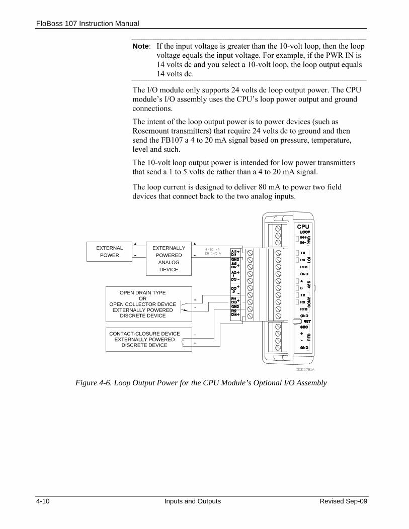
FloBoss 107 Instruction Manual
Note: If the input voltage is greater than the 10-volt loop, then the loop voltage equals the input voltage. For example, if the PWR IN is 14 volts dc and you select a 10-volt loop, the loop output equals 14 volts dc.
The I/O module only supports 24 volts dc loop output power. The CPU module’s I/O assembly uses the CPU’s loop power output and ground connections.
The intent of the loop output power is to power devices (such as Rosemount transmitters) that require 24 volts dc to ground and then send the FB107 a 4 to 20 mA signal based on pressure, temperature, level and such.
The 10-volt loop output power is intended for low power transmitters that send a 1 to 5 volts dc rather than a 4 to 20 mA signal.
The loop current is designed to deliver 80 mA to power two field devices that connect back to the two analog inputs.
EXTERNALLYPOWEREDPOWER
EXTERNAL
DEVICEANALOG
-
-+
DISCRETE DEVICEEXTERNALLY POWERED
CONTACT-CLOSURE DEVICE
DISCRETE DEVICEEXTERNALLY POWERED
OPEN COLLECTOR DEVICEOR
OPEN DRAIN TYPE
+
Figure 4-6. Loop Output Power for the CPU Module’s Optional I/O Assembly
4-10 Inputs and Outputs Revised Sep-09
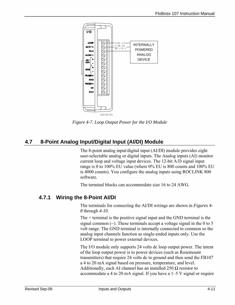
FloBoss 107 Instruction Manual
INTERNALLYPOWERED
DEVICEANALOG
Figure 4-7. Loop Output Power for the I/O Module
4.7 8-Point Analog Input/Digital Input (AI/DI) Module The 8-point analog input/digital input (AI/DI) module provides eight user-selectable analog or digital inputs. The Analog inputs (AI) monitor current loop and voltage input devices. The 12-bit A/D signal input range is 0 to 100% EU value (where 0% EU is 800 counts and 100% EU is 4000 counts). You configure the analog inputs using ROCLINK 800 software.
The terminal blocks can accommodate size 16 to 24 AWG.
4.7.1 Wiring the 8-Point AI/DI The terminals for connecting the AI/DI wirings are shown in Figures 4-8 through 4-10. The + terminal is the positive signal input and the GND terminal is the signal common (−). These terminals accept a voltage signal in the 0 to 5 volt range. The GND terminal is internally connected to common so the analog input channels function as single-ended inputs only. Use the LOOP terminal to power external devices.
The I/O module only supports 24 volts dc loop output power. The intent of the loop output power is to power devices (such as Rosemount transmitters) that require 24 volts dc to ground and then send the FB107 a 4 to 20 mA signal based on pressure, temperature, and level. Additionally, each AI channel has an installed 250 Ω resistor to accommodate a 4 to 20 mA signal. If you have a 1–5 V signal or require
Revised Sep-09 Inputs and Outputs 4-11
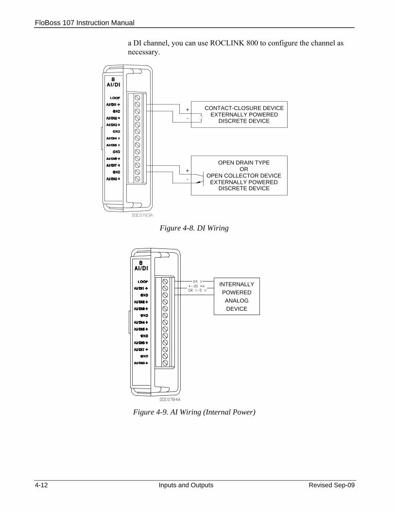
FloBoss 107 Instruction Manual
a DI channel, you can use ROCLINK 800 to configure the channel as necessary.
+-
OPEN DRAIN TYPEOR
OPEN COLLECTOR DEVICEEXTERNALLY POWERED
+-
CONTACT-CLOSURE DEVICEEXTERNALLY POWERED
DISCRETE DEVICE
DISCRETE DEVICE
Figure 4-8. DI Wiring
INTERNALLYPOWERED
DEVICEANALOG
Figure 4-9. AI Wiring (Internal Power)
4-12 Inputs and Outputs Revised Sep-09

FloBoss 107 Instruction Manual
EXTERNALLYPOWERED POWER
EXTERNAL
DEVICEANALOG
Figure 4-10. AI Wiring (External Power)
4.8 Analog Outputs (AO) The analog outputs (AO) provide a 4 to 20 mA current source output for powering analog loop devices. Analog outputs are analog signals the FB107 generates to regulate equipment, such as control valves or any device requiring analog control. The AO includes the power supply connections. The analog outputs use a 12-bit D/A converter with default A/D values of 0 and 3250 (0 to 100% EU values).
Note: Select AO as the I/O Type for the selectable analog output/discrete output when you configure it for use as an analog output. Refer to Figure 4-5.
4.8.1 Wiring the Analog Outputs The terminals provided on the CPU module for connecting AO wiring are are:
AO+ Positive AO− Common
Caution You can induce ground loops by tying commons from various modules together.
Figure 4-11 shows wiring for the analog output.
Revised Sep-09 Inputs and Outputs 4-13

FloBoss 107 Instruction Manual
INTERNALLYPOWERED
Figure 4-11. Analog Output Wiring (on CPU Module)
4.9 Discrete Inputs (DI) The discrete input (DI) monitors the status of relays, open collector/open drain type solid-state switches, and other two-state devices. Discrete inputs come from relays, switches, and other devices, which generate an on/off, open/close, or high/low signal.
The DI provides a source voltage for dry relay contacts or for an open-collector solid-state switch.
Each DI channel can be software-configured to function as: Standard discrete inputs. Latched discrete inputs.
A latched DI remains in the active state until reset. Other parameters can invert the field signal and gather statistical information on the number of transitions and the time accumulated in the on- or off-state.
The DI senses the low voltage (less that 0.5 V dc), which signals the FB107 electronics that the relay contacts have closed. The opening of the contacts allows the voltage to rise and the DI signals the FB107 electronics that the relay contacts have opened. An FB107 can read a DI a maximum of 20 times per second (50 millisecond scan).
When a field device (such as a relay contact or open collector) is connected across + and GND, the closing of the contacts completes the circuit This activates current flow that the DI circuitry senses and, in turn, signals the FB107 electronics indicating that the relay contacts have closed.
4-14 Inputs and Outputs Revised Sep-09

FloBoss 107 Instruction Manual
Note: Select DI as the I/O Type for the selectable pulse inputs/discrete inputs when you configure it for use as a discrete input. Refer to Figure 4-5.
4.9.1 Wiring the Discrete Inputs The terminals provided on the CPU module for connecting the DI wiring are shown in Figure 4-12. The + terminal is the positive signal input and the GND terminal is the signal common (−). The discrete input operates by providing a closed contact across terminals + and GND. Refer to Figure 4-12.
Caution You can induce ground loops by tying commons from various modules together. The discrete input is designed to operate only with non-powered discrete devices, such as “dry” relay contacts, open collector devices, or isolated solid state switches. Use of the DI channel with powered devices may cause improper operation or damage.
OR
OPEN DRAIN TYPEOR
OPEN COLLECTOR DEVICEEXTERNALLY POWERED
+-
CONTACT-CLOSURE DEVICEEXTERNALLY POWERED
+-
Figure 4-12. Discrete Input Wiring (on CPU Module)
4.10 Discrete Outputs (DO) The discrete output (DO) provides two-state outputs to energize solid-state relays and power small electrical loads. You can set a discrete output to send a pulse to a specified device. Discrete outputs are high and low outputs used to turn equipment on and off.
The DO circuitry is optically coupled to help isolate the processor board from the input signal. Refer to Figures 4-13 and 4-14.
Revised Sep-09 Inputs and Outputs 4-15

FloBoss 107 Instruction Manual
DO functions include: Sustained discrete outputs. Momentary discrete outputs. Toggled output. Time duration output.
The discrete output channel is a normally-open, FET switch. The discrete output is a solid-state switch enabled by individual signals from the processor I/O lines and capable of handling 50 Volts dc at 0.2 A maximum.
You configure the DO so that after a reset the DO retains the last value or switches off. When a request is made to change the state of a DO, the request is immediately sent to the DO. There is no scan time associated with a change of DO.
If the DO is in momentary or toggle mode, you can enter a minimum time-on of 50 milliseconds (.05 seconds).
Notes:
Select DO as the I/O Type for the selectable analog output/discrete output when you configure it for use as a discrete output. Refer to Figure 4-5.
When using the discrete output to drive an inductive load (such as a relay coil), place a suppression diode across the load. This protects the DO from the reverse Electro-Motive Force (EMF) spike generated when the inductive load is switched off.
4.10.1 Wiring the Discrete Outputs The terminals for connecting the DO wiring on the CPU module are shown in Figures 4-13 and 4-14. The “+” terminal is the high side of the switch and the “–” terminal is the low side.
Caution You can induce ground loops by tying commons from various modules together.
4-16 Inputs and Outputs Revised Sep-09

FloBoss 107 Instruction Manual
SWITCHEDDEVICESUPPLY
POWER
LOW SIDE SWITCH
Figure 4-13. Discrete Output Wiring - Low Side Switch(on CPU Module)
SWITCHEDDEVICESUPPLY
POWER
HIGH SIDE SWITCH
Figure 4-14. Discrete Output Wiring - High Side Switch (on CPU Module )
4.11 Discrete Outputs Relay (DOR) Module The Discrete Output Relay (DOR) module provides control over various discrete output field devices. An FB107 can support a maximum of six DOR modules.
DOR modules provide six channels of discrete outputs that may be set to send a control signal to a specified device. Refer to Figures 4-15 and
Revised Sep-09 Inputs and Outputs 4-17

FloBoss 107 Instruction Manual
4-16. Using ROCLINK 800 software, you can configure the module as latched, toggled, momentary, or Timed Duration Outputs (TDO).
The discrete output channel is a normally open contact. The discrete output is a relay switch enabled by individual signals from the processor I/O lines and capable of handling 30 Volts dc at 1.0 A maximum.
Additionally, one DOR channel makes the normally closed contact available to the field.
You configure the DOR so that it either retains the last value on reset or sets to a user-specified fail-safe value. When a request is made to change the state of a DO, the request is immediately sent to the DO.
If the DO is in momentary or toggle mode, you can enter a minimum time-on of 50 milliseconds (.05 seconds).
Note: When using the discrete output to drive an inductive load (such as a relay coil), place a suppression diode across the load. This protects the DO from the reverse Electro-Motive Force (EMF) spike generated when the inductive load is switched off.
4.11.1 Wiring the Discrete Output Relays The terminals for connecting the DO wiring are shown in Figures 4-15 and 4-16.
Caution You can induce ground loops by tying commons from various modules together.
SWITCHEDDEVICESUPPLY
POWERDO2-DO6
HIGH SIDE SWITCH
Figure 4-15. Discrete Output Relay Module Wiring (High Side Switch)
4-18 Inputs and Outputs Revised Sep-09

FloBoss 107 Instruction Manual
SWITCHEDDEVICESUPPLY
POWERDO2-DO6
LOW SIDE SWITCH
Figure 4-16. Discrete Output Relay Module Wiring (Low Side Switch)
4.12 Pulse Inputs (PI) Pulse inputs (PI) processes signals from pulse-generating devices and provide a calculated rate or an accumulated total over a configured period. The FB107 pulse input circuits are physically the same as the discrete inputs. The pulse input routes to a pulse accumulator, where the pulses are counted and accumulated.
The PI is most commonly used to interface to open collector/open drain type solid-state devices. Use the PI to interface to self-powered devices.
Acceptable PI voltage levels range between 0.5 volts dc (low) and 1.5 volts dc (high).
Caution The pulse input is designed to operate with non-powered devices, such as “dry” contacts or isolated solid-state switches. Use of the PI with externally powered devices may cause improper operation or damage.
Note: Select PI as the I/O Type for the selectable pulse inputs/discrete inputs when you configure it for use as a pulse input. Refer to Figure 4-5.
4.12.1 Wiring the Pulse Inputs Figure 4-17 shows the terminals on the CPU module for connecting the PI wiring. The + terminal is a positive source voltage; the GND terminal is the signal return.
Revised Sep-09 Inputs and Outputs 4-19

FloBoss 107 Instruction Manual
To use the channel as a pulse input, connect the + and GND field wires to terminals PI1+ or PI2+ and GND.
Caution You can induce ground loops by tying commons from various modules together.
INTERNALLYPOWERED
Figure 4-17. Pulse Input Wiring (on CPU Module)
4.13 Application (APP 485) Module The FB107 Application Module (labeled APP 485) provides a flexible storage and delivery mechanism for a variety of localized FB107 applications operating in the RS-485 physical environment. These might include a Gas Chromatograph application module (which would provide a Modbus interface between the FB107 and an external GC), a level sensor application, a Coriolis interface, or an ultrasonic interface.
Note: For detailed instructions on using these modules, refer to the specific documentation for those programs.
4.13.1 Wiring the Application Module Figure 4-18 shows an application module wired to a single external field device. Figure 4-19 shows typical wiring to several field devices.
Note: For self-contained applications, field wiring may be unnecessary.
4-20 Inputs and Outputs Revised Sep-09
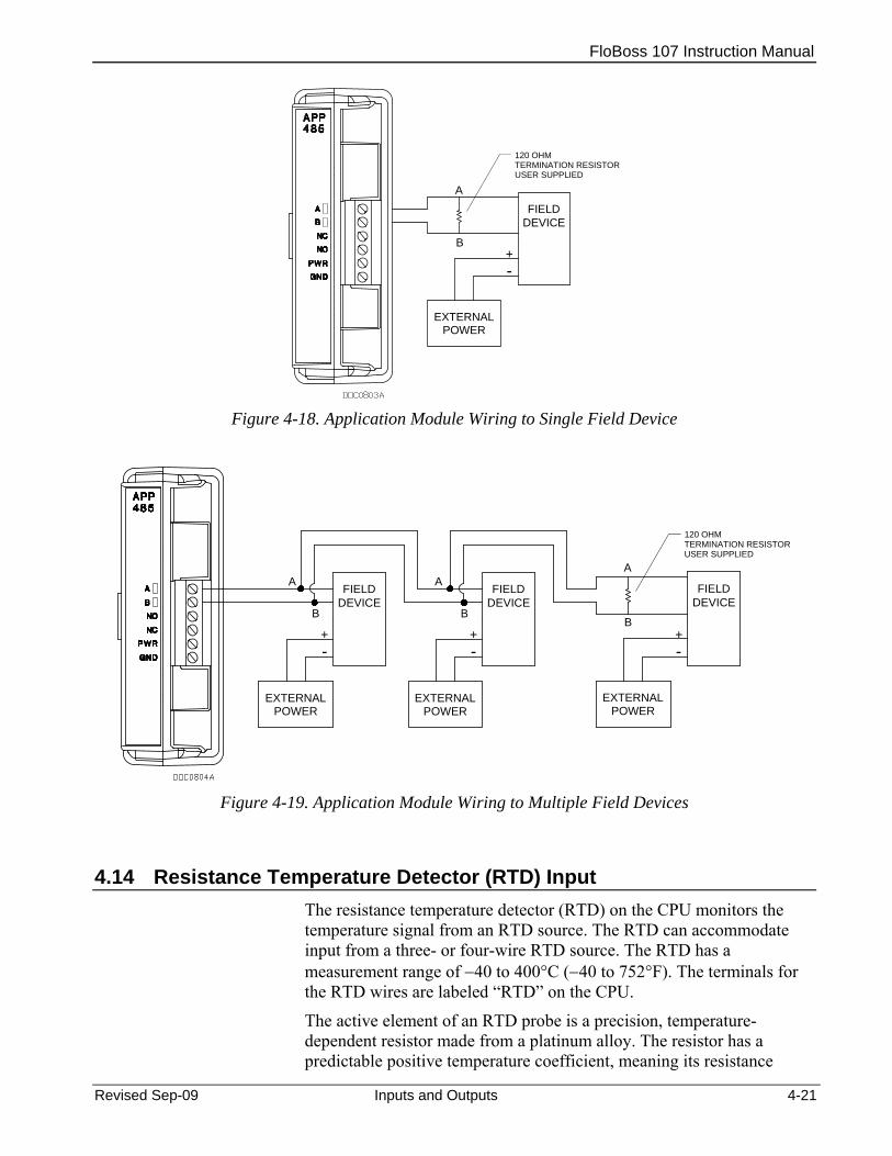
FloBoss 107 Instruction Manual
TERMINATION RESISTOR120 OHM
FIELDDEVICE
+-
EXTERNALPOWER
USER SUPPLIED
A
B
Figure 4-18. Application Module Wiring to Single Field Device
FIELDDEVICE
EXTERNALPOWERPOWER
EXTERNAL
-+
DEVICEFIELD
POWEREXTERNAL
DEVICEFIELD
USER SUPPLIED
120 OHMTERMINATION RESISTOR
+ +
A
B
A
B
A
B
- -
Figure 4-19. Application Module Wiring to Multiple Field Devices
4.14 Resistance Temperature Detector (RTD) Input The resistance temperature detector (RTD) on the CPU monitors the temperature signal from an RTD source. The RTD can accommodate input from a three- or four-wire RTD source. The RTD has a measurement range of −40 to 400°C (−40 to 752°F). The terminals for the RTD wires are labeled “RTD” on the CPU.
The active element of an RTD probe is a precision, temperature-dependent resistor made from a platinum alloy. The resistor has a predictable positive temperature coefficient, meaning its resistance
Revised Sep-09 Inputs and Outputs 4-21
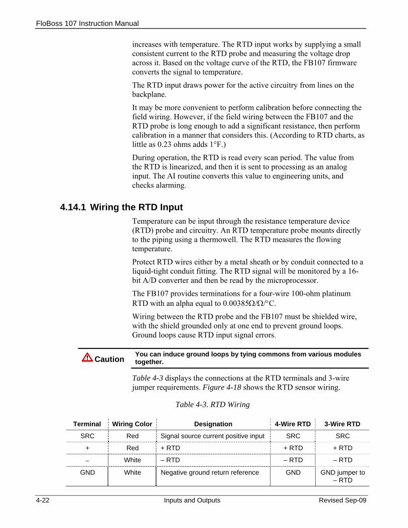
FloBoss 107 Instruction Manual
increases with temperature. The RTD input works by supplying a small consistent current to the RTD probe and measuring the voltage drop across it. Based on the voltage curve of the RTD, the FB107 firmware converts the signal to temperature.
The RTD input draws power for the active circuitry from lines on the backplane.
It may be more convenient to perform calibration before connecting the field wiring. However, if the field wiring between the FB107 and the RTD probe is long enough to add a significant resistance, then perform calibration in a manner that considers this. (According to RTD charts, as little as 0.23 ohms adds 1°F.)
During operation, the RTD is read every scan period. The value from the RTD is linearized, and then it is sent to processing as an analog input. The AI routine converts this value to engineering units, and checks alarming.
4.14.1 Wiring the RTD Input Temperature can be input through the resistance temperature device (RTD) probe and circuitry. An RTD temperature probe mounts directly to the piping using a thermowell. The RTD measures the flowing temperature.
Protect RTD wires either by a metal sheath or by conduit connected to a liquid-tight conduit fitting. The RTD signal will be monitored by a 16-bit A/D converter and then be read by the microprocessor.
The FB107 provides terminations for a four-wire 100-ohm platinum RTD with an alpha equal to 0.00385Ω/Ω/°C.
Wiring between the RTD probe and the FB107 must be shielded wire, with the shield grounded only at one end to prevent ground loops. Ground loops cause RTD input signal errors.
Caution You can induce ground loops by tying commons from various modules together.
Table 4-3 displays the connections at the RTD terminals and 3-wire jumper requirements. Figure 4-18 shows the RTD sensor wiring.
Table 4-3. RTD Wiring
Terminal Wiring Color Designation 4-Wire RTD 3-Wire RTD
SRC Red Signal source current positive input SRC SRC
+ Red + RTD + RTD + RTD
− White – RTD – RTD – RTD
GND White Negative ground return reference GND GND jumper to – RTD
4-22 Inputs and Outputs Revised Sep-09
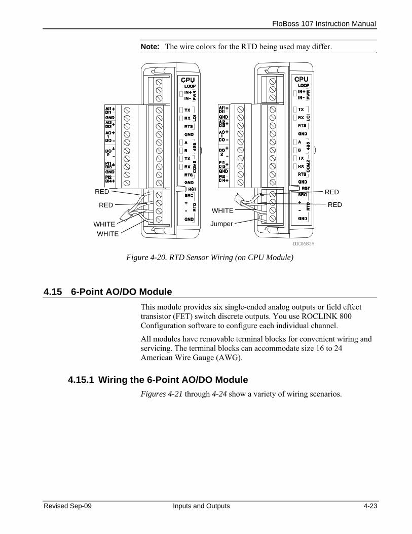
FloBoss 107 Instruction Manual
Note: The wire colors for the RTD being used may differ.
RED RED
Revised Sep-09 Inputs and Outputs 4-23
Figure 4-20. RTD Sensor Wiring (on CPU Module)
4.15 6-Point AO/DO Module This module provides six single-ended analog outputs or field effect transistor (FET) switch discrete outputs. You use ROCLINK 800 Configuration software to configure each individual channel.
All modules have removable terminal blocks for convenient wiring and servicing. The terminal blocks can accommodate size 16 to 24 American Wire Gauge (AWG).
4.15.1 Wiring the 6-Point AO/DO Module Figures 4-21 through 4-24 show a variety of wiring scenarios.
RED REDWHITE
JumperWHITEWHITE

FloBoss 107 Instruction Manual
Figure 4-21. Analog Output 4-20 mA Wiring Figure 4-22. Analog Output 1-5 V Wiring
DEVICEPOWERSOURCE
DEVICEPOWERSOURCE
Figure 4-23. Discrete Output High Side Switch
Wiring Figure 4-24. Discrete Output Low Side Switch
Wiring
4.16 HART® Module The HART (Highway Addressable Remote Transducer) module enables communications between the FB107 and HART devices using the HART protocol. The HART module receives signals from and transmits signals to HART devices.
The module has four input/output channels. Software-configurable switches on the module enable you to set each channel. A channel configured as input can be used in a point-to-point or multi-drop mode. A channel configured as output can be used only in point-to-point mode.
In multi-drop mode, you can connect as many as five HART devices (in parallel) to each channel. With all four channels in multi-drop mode, the FB107 can support as many as 20 HART devices.
4-24 Inputs and Outputs Revised Sep-09

FloBoss 107 Instruction Manual
An FB107 equipped with a HART module is considered to be a HART host (primary master) interface with a Class 1 Conformance classification. You can use ROCLINK 800 Configuration software to configure the module as a secondary master.
4.16.1 Wiring the HART Module Figures 4-25 through 4-27 show a variety of wiring scenarios.
Figure 4-25. HART Input Point-to-Point Wiring
Figure 4-26. HART Input Multi-Drop Wiring
Figure 4-27. HART Output Wiring
Revised Sep-09 Inputs and Outputs 4-25
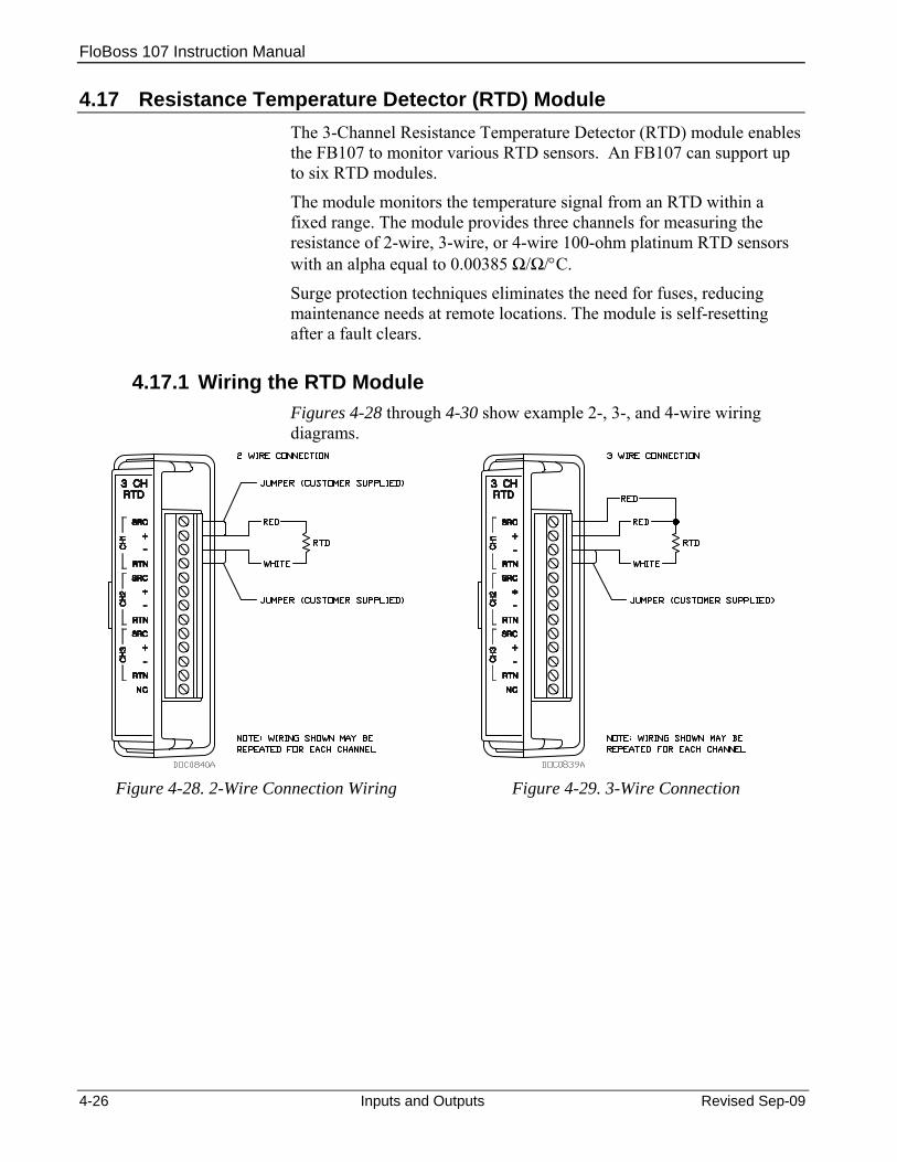
FloBoss 107 Instruction Manual
4.17 Resistance Temperature Detector (RTD) Module The 3-Channel Resistance Temperature Detector (RTD) module enables the FB107 to monitor various RTD sensors. An FB107 can support up to six RTD modules.
The module monitors the temperature signal from an RTD within a fixed range. The module provides three channels for measuring the resistance of 2-wire, 3-wire, or 4-wire 100-ohm platinum RTD sensors with an alpha equal to 0.00385 Ω/Ω/°C.
Surge protection techniques eliminates the need for fuses, reducing maintenance needs at remote locations. The module is self-resetting after a fault clears.
4.17.1 Wiring the RTD Module Figures 4-28 through 4-30 show example 2-, 3-, and 4-wire wiring diagrams.
Figure 4-28. 2-Wire Connection Wiring Figure 4-29. 3-Wire Connection
4-26 Inputs and Outputs Revised Sep-09
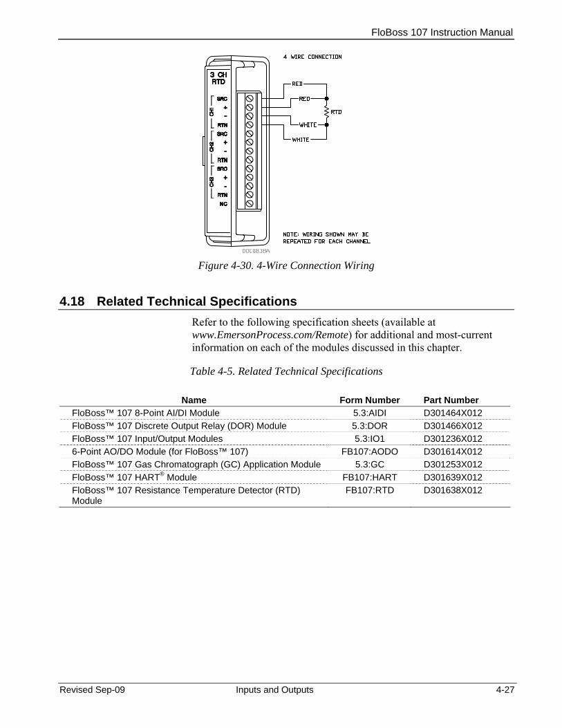
FloBoss 107 Instruction Manual
Figure 4-30. 4-Wire Connection Wiring
4.18 Related Technical Specifications Refer to the following specification sheets (available at www.EmersonProcess.com/Remote) for additional and most-current information on each of the modules discussed in this chapter.
Table 4-5. Related Technical Specifications
Name Form Number Part Number FloBoss™ 107 8-Point AI/DI Module 5.3:AIDI D301464X012 FloBoss™ 107 Discrete Output Relay (DOR) Module 5.3:DOR D301466X012 FloBoss™ 107 Input/Output Modules 5.3:IO1 D301236X012 6-Point AO/DO Module (for FloBoss™ 107) FB107:AODO D301614X012 FloBoss™ 107 Gas Chromatograph (GC) Application Module 5.3:GC D301253X012 FloBoss™ 107 HART® Module FB107:HART D301639X012 FloBoss™ 107 Resistance Temperature Detector (RTD) Module
FB107:RTD D301638X012
Revised Sep-09 Inputs and Outputs 4-27

FloBoss 107 Instruction Manual
4-28 Inputs and Outputs Revised Sep-09
[This page is intentionally left blank]

FloBoss 107 Instruction Manual
Chapter 5 – Communications
The FB107 communicates to external devices through its local operator interface port (LOI), the COM1 EIA-485 (RS-485) port, the COM2 EIA-232 (RS-232 port), or optionally on COM3 using a communications module.
Note: You can place communication modules only in slots 1 and 2 on the FB107 base unit.
The communication terminals and communication modules provide communications between the FB107 and a host system or external devices. The communication modules install directly onto the FB107 backplane and activate the host port when installed.
Warning Always ensure that the area is non-hazardous before you make any communication connections (RS-232, RS-485, Ethernet, USB, etc.).
In This Chapter
5.1 Communications Overview .................................................................5-1 5.2 Installing/Removing a Communication Module ..................................5-4 5.3 Wiring the Local Operator Interface (LOI) Port...................................5-5
5.3.1 Using the LOI.........................................................................5-6 5.4 Wiring EIA-485 (RS-485) Communications ........................................5-6 5.5 Wiring EIA-232 (RS-232) Communications ........................................5-7 5.6 Liquid Crystal Display (LCD) Touchpad .............................................5-8 5.7 Enhanced Communication Module (ECM) .........................................5-9
5.7.1 Activating the USB Port .......................................................5-10 5.8 Dial-Up Modem Module ....................................................................5-15 5.9 Related Technical Specifications......................................................5-16
5.1 Communications Overview The FB107 CPU module provides three built-in communication ports. You can also install communication modules in slots 1 and 2 in the base unit.
Revised Sep-09 Communications 5-1
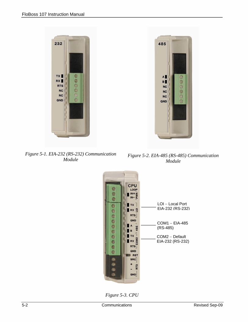
FloBoss 107 Instruction Manual
Figure 5-1. EIA-232 (RS-232) Communication Module
Figure 5-2. EIA-485 (RS-485) Communication Module
LOI − Local Port EIA-232 (RS-232)
COM1 − EIA-485 (RS-485)
COM2 − Default EIA-232 (RS-232)
Figure 5-3. CPU
5-2 Communications Revised Sep-09
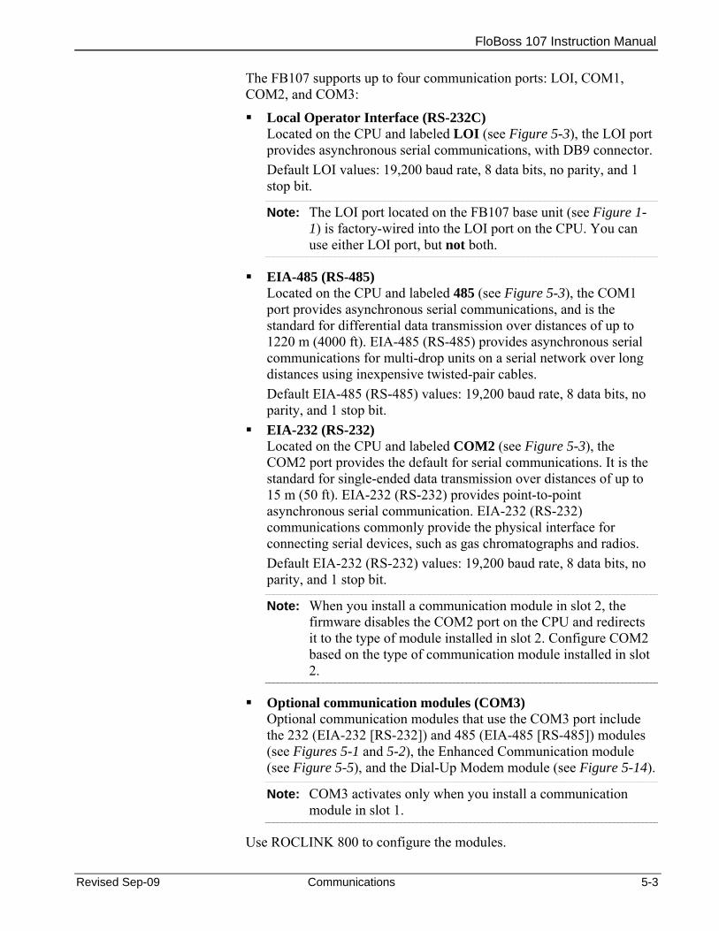
FloBoss 107 Instruction Manual
Revised Sep-09 Communications 5-3
The FB107 supports up to four communication ports: LOI, COM1, COM2, and COM3:
Local Operator Interface (RS-232C) Located on the CPU and labeled LOI (see Figure 5-3), the LOI port provides asynchronous serial communications, with DB9 connector. Default LOI values: 19,200 baud rate, 8 data bits, no parity, and 1 stop bit.
Note: The LOI port located on the FB107 base unit (see Figure 1-1) is factory-wired into the LOI port on the CPU. You can use either LOI port, but not both.
EIA-485 (RS-485) Located on the CPU and labeled 485 (see Figure 5-3), the COM1 port provides asynchronous serial communications, and is the standard for differential data transmission over distances of up to 1220 m (4000 ft). EIA-485 (RS-485) provides asynchronous serial communications for multi-drop units on a serial network over long distances using inexpensive twisted-pair cables. Default EIA-485 (RS-485) values: 19,200 baud rate, 8 data bits, no parity, and 1 stop bit.
EIA-232 (RS-232) Located on the CPU and labeled COM2 (see Figure 5-3), the COM2 port provides the default for serial communications. It is the standard for single-ended data transmission over distances of up to 15 m (50 ft). EIA-232 (RS-232) provides point-to-point asynchronous serial communication. EIA-232 (RS-232) communications commonly provide the physical interface for connecting serial devices, such as gas chromatographs and radios. Default EIA-232 (RS-232) values: 19,200 baud rate, 8 data bits, no parity, and 1 stop bit.
Note: When you install a communication module in slot 2, the firmware disables the COM2 port on the CPU and redirects it to the type of module installed in slot 2. Configure COM2 based on the type of communication module installed in slot 2.
Optional communication modules (COM3) Optional communication modules that use the COM3 port include the 232 (EIA-232 [RS-232]) and 485 (EIA-485 [RS-485]) modules (see Figures 5-1 and 5-2), the Enhanced Communication module (see Figure 5-5), and the Dial-Up Modem module (see Figure 5-14).
Note: COM3 activates only when you install a communication module in slot 1.
Use ROCLINK 800 to configure the modules.
FloBoss 107 Instruction Manual
5-4 Communications Revised Sep-09
Each communication module uses a separate, single-ended channel from the other modules. The field interface protects the electronics in the module.
LEDs display the RX (receive) and TX (transmit) signals for EIA-232 (RS-232) communications.
LEDs display the A (transmit/receive+) and B (transmit/receive −) signals for EIA-485 (RS-485) communications.
Communication Protocols
The FB107 has the capability to communicate with other devices using ROC or Modbus protocols. The firmware can automatically detect the two protocols (ROC or Modbus) at baud rates of up to 115.2 Kbps. ROC protocol supports serial communications to local or remote devices, such as a host computer.
An FB107 can act as a Modbus host or slave device using Remote Terminal Unit (RTU) or American Standard Code for Information Interchange (ASCII) modes. This allows you to easily integrate the FB107 into other systems. Extensions to the Modbus protocol allow the retrieval of history, event, and alarm data in Electronic Flow Metering (EFM) Measurement applications.
Note: The LOI port only supports ROC or Modbus slave protocols.
5.2 Installing/Removing a Communication Module All FB107 modules are designed for ease of installation and removal. Refer to Installing a Module, Removing a Module, and Wiring a Module in Chapter 4, Inputs/Outputs and RTD Inputs, for specific instructions.
You can install communication modules in slots 1 or 2 on the base unit, which provides power and control signals to those modules.
Slot 1 Installing a communication module in slot 1 on the base unit activates COM3. COM2 is not affected; it still resides on the CPU. COM3 is completely independent of any other communication port.
Note: When you install a communication module in slot 1, you can also install an I/O module in slot 7. This provides a full complement of 6 I/O modules and four communication ports.
Slot 2 Installing a communication module in slot 2 on the base unit disconnects the CPU module’s COM2 and redirects COM2 to the newly installed communication module. COM2 always exists.
Note: When you install a communication module in slot 2, the firmware redirects the CPU module’s communication port (COM2) to the type of module installed in slot 2. Configure COM2 based on the type of communication module installed in slot 2.
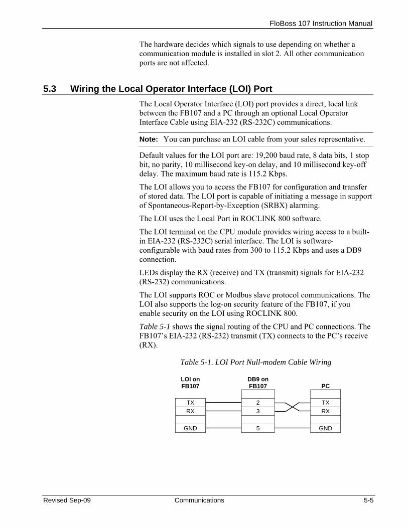
FloBoss 107 Instruction Manual
The hardware decides which signals to use depending on whether a communication module is installed in slot 2. All other communication ports are not affected.
5.3 Wiring the Local Operator Interface (LOI) Port The Local Operator Interface (LOI) port provides a direct, local link between the FB107 and a PC through an optional Local Operator Interface Cable using EIA-232 (RS-232C) communications.
Note: You can purchase an LOI cable from your sales representative.
Default values for the LOI port are: 19,200 baud rate, 8 data bits, 1 stop bit, no parity, 10 millisecond key-on delay, and 10 millisecond key-off delay. The maximum baud rate is 115.2 Kbps.
The LOI allows you to access the FB107 for configuration and transfer of stored data. The LOI port is capable of initiating a message in support of Spontaneous-Report-by-Exception (SRBX) alarming.
The LOI uses the Local Port in ROCLINK 800 software.
The LOI terminal on the CPU module provides wiring access to a built-in EIA-232 (RS-232C) serial interface. The LOI is software-configurable with baud rates from 300 to 115.2 Kbps and uses a DB9 connection.
LEDs display the RX (receive) and TX (transmit) signals for EIA-232 (RS-232) communications.
The LOI supports ROC or Modbus slave protocol communications. The LOI also supports the log-on security feature of the FB107, if you enable security on the LOI using ROCLINK 800.
Table 5-1 shows the signal routing of the CPU and PC connections. The FB107’s EIA-232 (RS-232) transmit (TX) connects to the PC’s receive (RX).
Table 5-1. LOI Port Null-modem Cable Wiring
LOI on FB107
DB9 on FB107 PC
TX 2 TX RX 3 RX
GND 5 GND
Revised Sep-09 Communications 5-5

FloBoss 107 Instruction Manual
5-6 Communications Revised Sep-09
5.3.1 Using the LOI 1. Plug the LOI cable into the LOI connector on the top of the FB107
base unit.
2. Connect the LOI cable to the PC’s COM port.
3. Connect to ROCLINK 800 software and log in.
4. Click the Direct Connect icon.
5. Configure communications for the other built-in and modular communications, I/O modules, AGA meter parameters, and other configuration parameters.
5.4 Wiring EIA-485 (RS-485) Communications The EIA-485 communications provides for RS-485 signals on: COM1 port located on the CPU (labeled 485). COM2 located on the CPU when a communications module is
installed in slot 2. COM3 located on the EIA-485 (RS-485) communications module
installed in slot 1.
Table 5-2 shows termination points for EIA-485 (RS-485) communications.
The EIA-485 (RS-485) serial communication allows baud rates from 300 to 115.2 Kbps with standard differential data transmissions over distances of up to 1220 meter (4000 feet). The EIA-485 (RS-485) drivers are designed for multi-point applications with multiple devices on a single bus.
EIA-485 (RS-485) supports the log-on security feature of the FB107 if you enable security on the communication port using ROCLINK 800.
LEDs display the A (transmit/receive+) and B (transmit/receive −) signals for EIA-485 (RS-485) communications.
Default values for the EIA-485 (RS-485) communication module are: 19,200 baud rate, 8 data bits, 1 stop bit, no parity, 10 millisecond key-on delay, and 10 millisecond key-off delay. The maximum baud rate is 115.2 Kbps.
Use twisted-pair cable for wiring. Ensure that you connect terminal A of FB107 to terminal A of 485 device using RS-485 communications (such as a gas chromatograph) and terminal B of the FB107 to terminal B of the device. Should you encounter difficulties establishing a connection, try reversing the connections.
Note: EIA-485 (RS-485) standards suggest placing a terminating resistor at the end of the line. The value of each termination
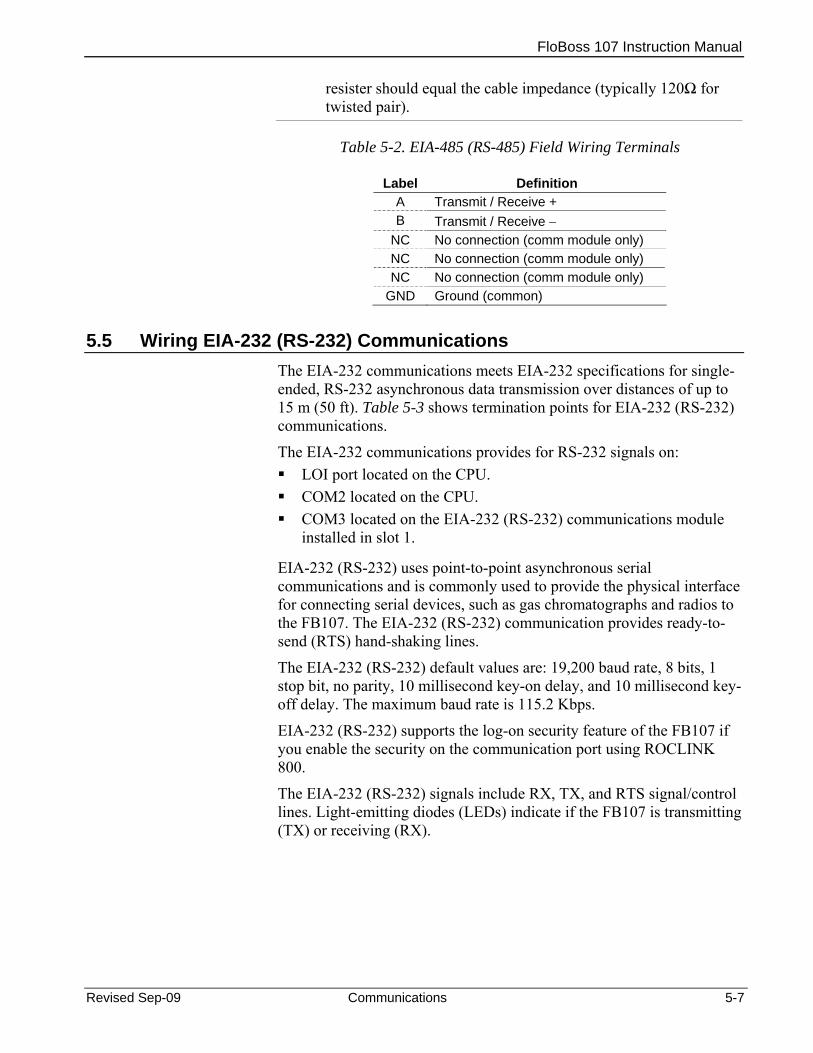
FloBoss 107 Instruction Manual
Revised Sep-09 Communications 5-7
resister should equal the cable impedance (typically 120Ω for twisted pair).
Table 5-2. EIA-485 (RS-485) Field Wiring Terminals
Label Definition A Transmit / Receive + B Transmit / Receive −
NC No connection (comm module only) NC No connection (comm module only) NC No connection (comm module only)
GND Ground (common)
5.5 Wiring EIA-232 (RS-232) Communications The EIA-232 communications meets EIA-232 specifications for single-ended, RS-232 asynchronous data transmission over distances of up to 15 m (50 ft). Table 5-3 shows termination points for EIA-232 (RS-232) communications.
The EIA-232 communications provides for RS-232 signals on: LOI port located on the CPU. COM2 located on the CPU. COM3 located on the EIA-232 (RS-232) communications module
installed in slot 1.
EIA-232 (RS-232) uses point-to-point asynchronous serial communications and is commonly used to provide the physical interface for connecting serial devices, such as gas chromatographs and radios to the FB107. The EIA-232 (RS-232) communication provides ready-to-send (RTS) hand-shaking lines.
The EIA-232 (RS-232) default values are: 19,200 baud rate, 8 bits, 1 stop bit, no parity, 10 millisecond key-on delay, and 10 millisecond key-off delay. The maximum baud rate is 115.2 Kbps.
EIA-232 (RS-232) supports the log-on security feature of the FB107 if you enable the security on the communication port using ROCLINK 800.
The EIA-232 (RS-232) signals include RX, TX, and RTS signal/control lines. Light-emitting diodes (LEDs) indicate if the FB107 is transmitting (TX) or receiving (RX).
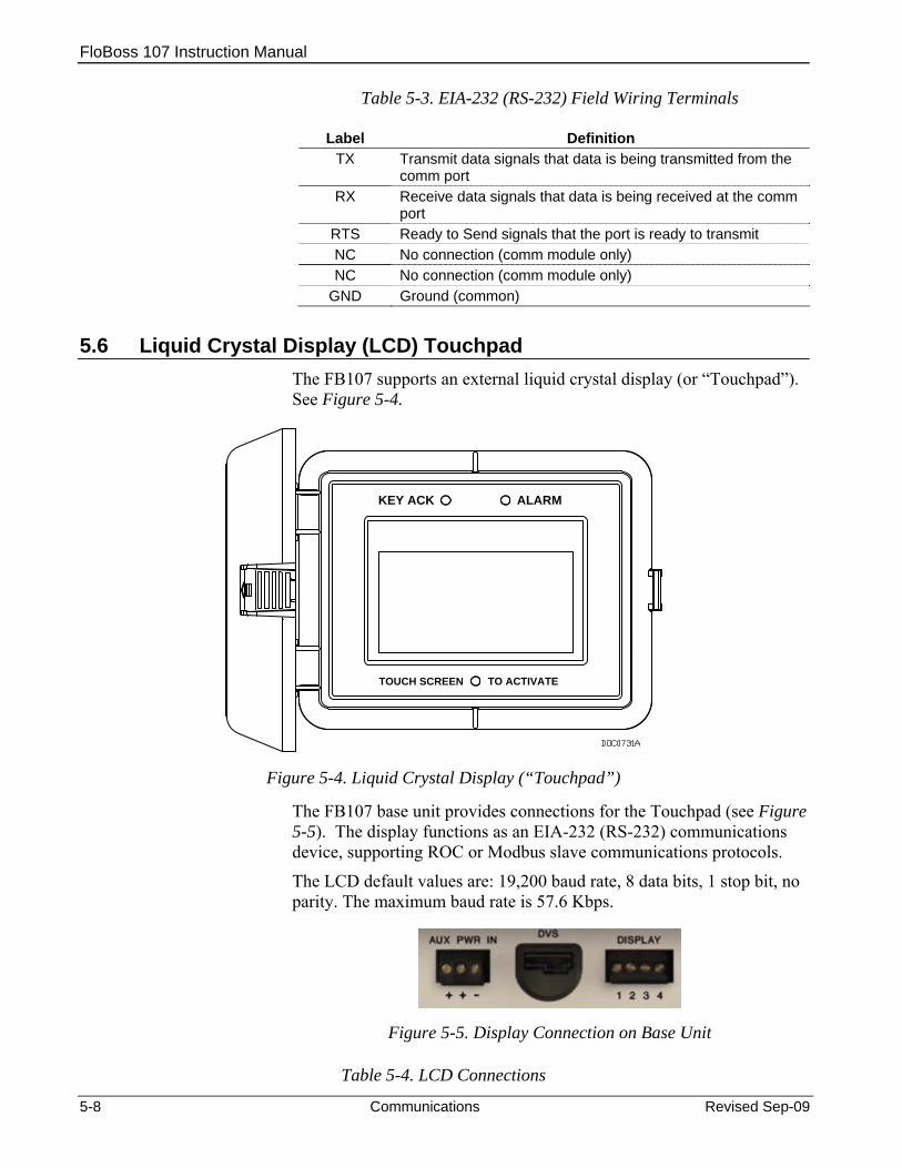
FloBoss 107 Instruction Manual
Table 5-3. EIA-232 (RS-232) Field Wiring Terminals
Label Definition TX Transmit data signals that data is being transmitted from the
comm port RX Receive data signals that data is being received at the comm
port RTS Ready to Send signals that the port is ready to transmit NC No connection (comm module only) NC No connection (comm module only)
GND Ground (common)
5.6 Liquid Crystal Display (LCD) Touchpad The FB107 supports an external liquid crystal display (or “Touchpad”). See Figure 5-4.
ALARMKEY ACK
TO ACTIVATETOUCH SCREEN
Figure 5-4. Liquid Crystal Display (“Touchpad”)
The FB107 base unit provides connections for the Touchpad (see Figure 5-5). The display functions as an EIA-232 (RS-232) communications device, supporting ROC or Modbus slave communications protocols.
The LCD default values are: 19,200 baud rate, 8 data bits, 1 stop bit, no parity. The maximum baud rate is 57.6 Kbps.
Figure 5-5. Display Connection on Base Unit
Table 5-4. LCD Connections
5-8 Communications Revised Sep-09
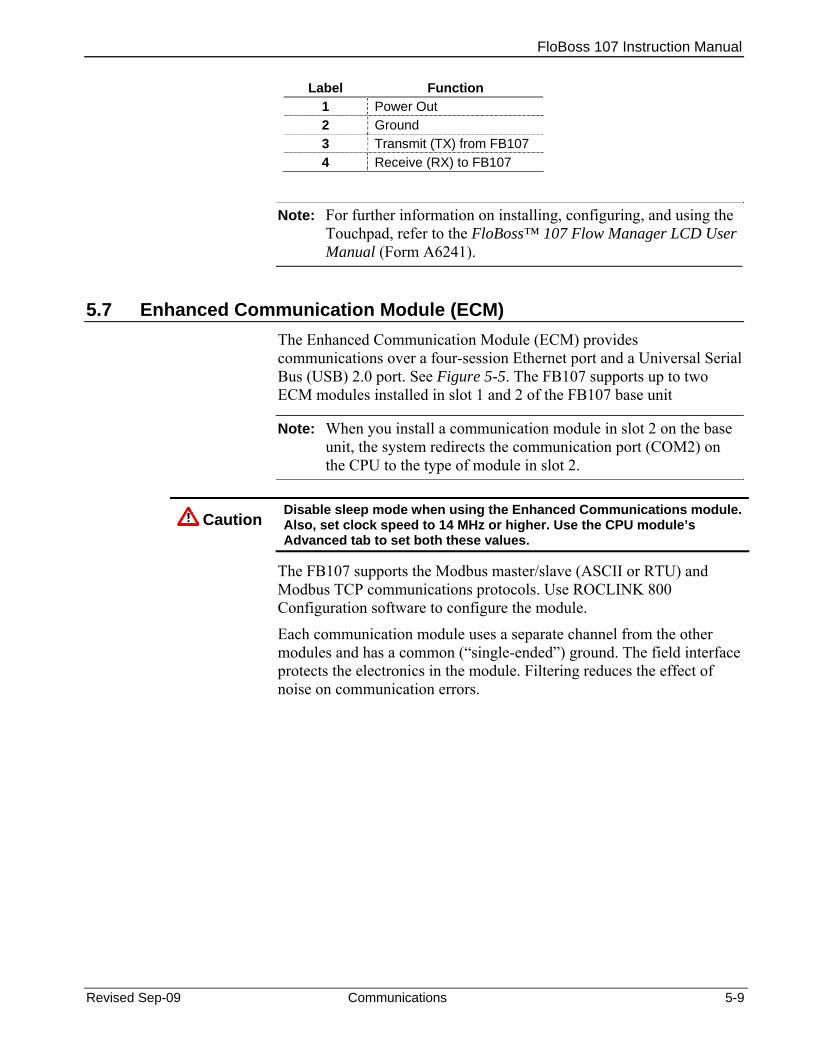
FloBoss 107 Instruction Manual
Label Function 1 Power Out 2 Ground 3 Transmit (TX) from FB107 4 Receive (RX) to FB107
Note: For further information on installing, configuring, and using the Touchpad, refer to the FloBoss™ 107 Flow Manager LCD User Manual (Form A6241).
5.7 Enhanced Communication Module (ECM) The Enhanced Communication Module (ECM) provides communications over a four-session Ethernet port and a Universal Serial Bus (USB) 2.0 port. See Figure 5-5. The FB107 supports up to two ECM modules installed in slot 1 and 2 of the FB107 base unit
Note: When you install a communication module in slot 2 on the base unit, the system redirects the communication port (COM2) on the CPU to the type of module in slot 2.
Caution Disable sleep mode when using the Enhanced Communications module. Also, set clock speed to 14 MHz or higher. Use the CPU module’s Advanced tab to set both these values.
The FB107 supports the Modbus master/slave (ASCII or RTU) and Modbus TCP communications protocols. Use ROCLINK 800 Configuration software to configure the module.
Each communication module uses a separate channel from the other modules and has a common (“single-ended”) ground. The field interface protects the electronics in the module. Filtering reduces the effect of noise on communication errors.
Revised Sep-09 Communications 5-9

FloBoss 107 Instruction Manual
Figure 5-5. Enhanced Communication Module (ECM)
5.7.1 Activating the USB Port The ECM includes a USB port that provides local operator interface (LOI) functions when the configuring laptop may not have a serial (RS-232) port.
Installing the USB Driver
You must install a USB driver to activate the USB port in the ECM. ROCLINK 800 (Version 1.85 and higher) provides this file (ECM_USB_DRIVER.inf).
Note: Before you begin this installation process, verify that you have installed Version 1.85 (or higher) of ROCLINK 800 and version 1.30 (or higher) of the FB107 firmware. Also, if your PC already has this particular USB driver installed, the USB connection is automatic.
Once Windows detects a new device driver, it starts a wizard to lead you through the installation process. The first screen displays automatically:
5-10 Communications Revised Sep-09

FloBoss 107 Instruction Manual
Figure 5-6. Pop-up Menu
Select No, not this time and click Next.
Figure 5-7. Pop-up Menu
Select Install from a list or specific location (Advanced) and click Next.
Revised Sep-09 Communications 5-11

FloBoss 107 Instruction Manual
Figure 5-8. Pop-up Menu
Select Search for the best driver…, deselect Search removable media…, click Browse to identify a general location for the USB driver file, and click Next.
Figure 5-9. Pop-up Menu
The wizard finds the ECM_USB_DRIVER.inf file and begins the installation process.
5-12 Communications Revised Sep-09
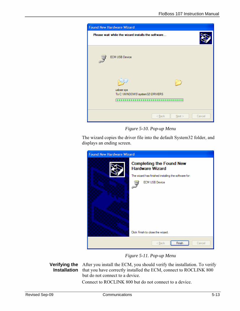
FloBoss 107 Instruction Manual
Figure 5-10. Pop-up Menu
The wizard copies the driver file into the default System32 folder, and displays an ending screen.
Figure 5-11. Pop-up Menu
Verifying the Installation
After you install the ECM, you should verify the installation. To verify that you have correctly installed the ECM, connect to ROCLINK 800 but do not connect to a device. Connect to ROCLINK 800 but do not connect to a device.
Revised Sep-09 Communications 5-13
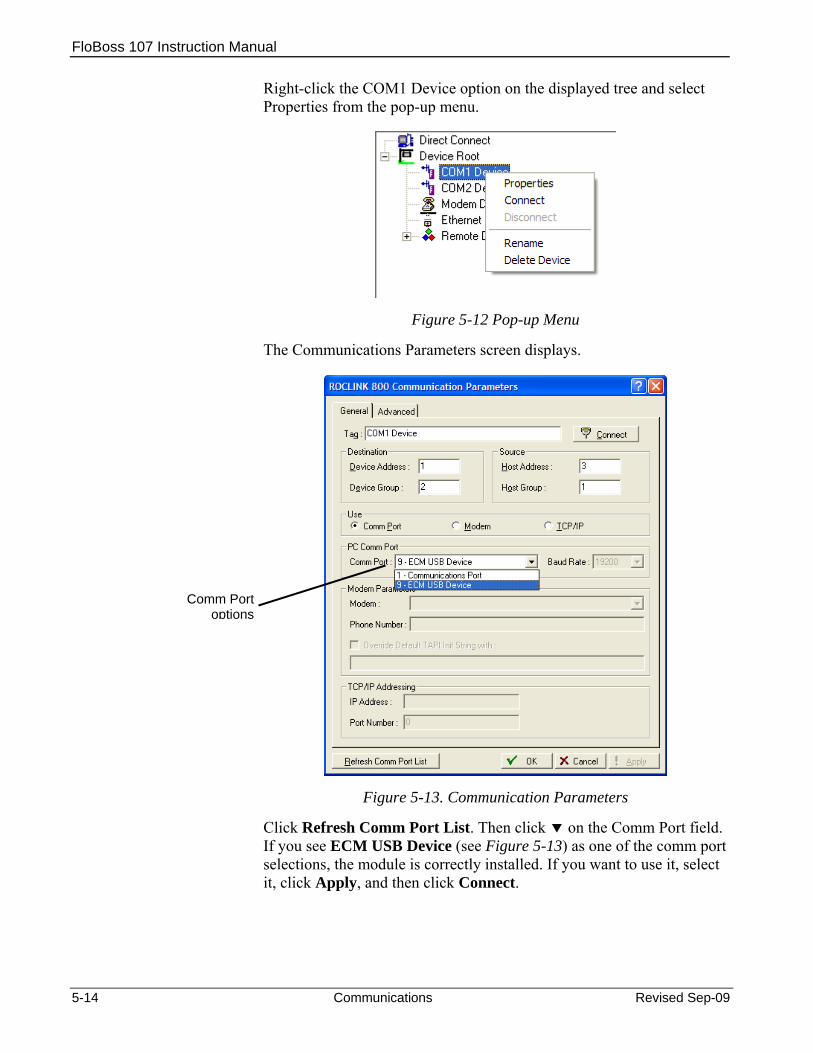
FloBoss 107 Instruction Manual
Right-click the COM1 Device option on the displayed tree and select Properties from the pop-up menu.
Figure 5-12 Pop-up Menu
The Communications Parameters screen displays.
Comm Port options
Figure 5-13. Communication Parameters
Click Refresh Comm Port List. Then click on the Comm Port field. If you see ECM USB Device (see Figure 5-13) as one of the comm port selections, the module is correctly installed. If you want to use it, select it, click Apply, and then click Connect.
5-14 Communications Revised Sep-09

FloBoss 107 Instruction Manual
5.8 Dial-Up Modem Module The Dial-Up Modem module provides communication over a public-switched telephone network (PSTN) at up to 2400 bits per second (bps). The module plugs into slots 1 or 2 of the FB107 base unit, which provides power and control signals to activate COM2 or COM3. See Figure 5-14.
The module is FCC part 68 approved for use with public-switched telephone networks (PSTNs). A label on the side of the module casing provides the FCC registration number and the ringer equivalent.
Note: When you install a communication module in slot 2 on the base unit, the system redirects the communication port (COM2) on the CPU to the type of module in slot 2.
Each communication module uses a separate channel from the other modules and has a common (“single-ended”) ground. The field interface protects the electronics in the module. Filtering reduces the effect of noise on communication errors.
The module has removable terminal blocks for convenient wiring and servicing. The terminal blocks can accommodate size 16 to 24 American Wire Gauge (AWG). The module uses a standard “tip and ring” PSTN wiring schema.
Figure 5-14. Dial-Up Modem Module
Revised Sep-09 Communications 5-15

FloBoss 107 Instruction Manual
5-16 Communications Revised Sep-09
5.9 Related Technical Specifications Refer to the following specification sheets (available at www.EmersonProcess.com/Remote) for additional and most-current information on each of the modules discussed in this chapter.
Table 5-5. Related Technical Specifications
Name Form Number Part Number FloBoss™ 107 Communication Modules 5.3:COM D301237X012 FloBoss™ 107 Multi-Variable Sensor (MVS) Modules 5.3:MVS D301239X012 FloBoss™ 107 LCD Touchpad 5.3:LCD D301241X012 FloBoss™ 107 Enhanced Communication Module FB107:ECM D301639X012 FloBoss™ 107 Dial-Up Modem Module FB107:DIAL D301643X012
FloBoss 107 Instruction Manual
Revised Sep-09 Sensors and Transducers 6-1
Chapter 6 – Sensors and Transducers
The FB107 supports a Multi-Variable Sensor (MVS) module, which plugs into any module slot (1 through 7) in the base unit or the expansion rack. It also supports a Dual Variable Sensor (DVS) and a Pressure module (PM), either of which attaches to the FB107 enclosure and connects to the DVS port on the FB107 base unit.
In This Chapter
6.1 Multi-Variable Sensor (MVS) Module Overview .......................... 6-1 6.1.1 Installing/Removing an MVS Module.............................. 6-3 6.1.2 Configuring a Multi-drop MVS Module Setup ................. 6-3 6.1.3 Lightning Protection........................................................ 6-6
6.2 Dual Variable Sensor (DVS) Overview........................................ 6-6 6.2.1 Installing/Removing a DVS............................................. 6-7 6.2.2 Physically Connecting a DVS ......................................... 6-9 6.2.3 Configuring a DVS........................................................ 6-10
6.3 Pressure Module (PM) Overview............................................... 6-11 6.3.1 Installing/Removing a Pressure Module....................... 6-12 6.3.2 Configuring a Pressure Module .................................... 6-13
6.1 Multi-Variable Sensor (MVS) Module Overview The MVS module provides communications and power to remote MVS transmitters and, in turn, provides differential pressure, static pressure, and temperature inputs to the FB107 for orifice flow calculations.
The module consists of interface electronics that provide the communications link between the FB107 and up to six MVS transmitters. The interface electronics controls communications with the sensor module, provides scaling of process variables, aids calibration, stores operating parameters, performs protocol conversion, and responds to requests from the FB107.
The module provides the communications interface and the short-circuit current-limited power required to connect up to six MVS transmitters. You can install the MVS module in any slot on the FB107 and expansion rack except for slot 0, where the CPU module resides.
You can connect up to six MVS transmitters to the FB107’s communications bus in a multi-drop connection scheme. You must set the address of each transmitter before you finalize the wiring of multiple transmitters. For proper operation of multiple MVS devices, each transmitter must have a unique address (in the range 1 through 255). None of the addresses can be 0 or 240.

FloBoss 107 Instruction Manual
Note: You set values for MVS transmitters using ROCLINK 800’s MVS Sensor screen (Configure > I/O > MVS Sensor).
Once you set a unique address for each transmitter, connect the transmitters in a multi-drop (or “daisy-chair”) configuration (see Figure 6-2). The only requirement for multi-drop wiring is that you tie all like terminals together. This means all the “A” terminals on the devices are electrically connected to the FB107’s “A” terminal and so on.
MVS modules have removable terminal blocks for convenient wiring and servicing. The terminal blocks can accommodate size 16 to 24 AWG.
The FB107 scans each MVS transmitter once every second, accessing values for differential pressure, static pressure, and temperature as inputs for flow calculations, history, calibration, and alarming.
Each input unit is based on selected system units:
Differential Pressure
Units
Static Pressure
Units
Temperature Units
English Units InH2O PSI Deg F
Metric Units kPa kPa Deg C
Figure 6-1. MVS Wiring
6-2 Sensors and Transducers Revised Sep-09
FloBoss 107 Instruction Manual
MVS Transmitters
The MVS transmitter provides static pressure, differential pressure, and process temperature inputs. It functions as a remote unit that communicates via a serial format. The transmitter measures the three flow-related variables simultaneously. These variables are continuously available to the FB107 that polls the MVS.
The transmitter consists of a transducer and an interface circuit. The transducer, contained in the sensor body, uses capacitance-cell technology to sense differential pressure and piezo-resistive technology to sense the static (absolute or gauge) pressure.
The transducer’s electronics convert the pressure variables directly into a digital format, allowing accurate correction and compensation. A microprocessor linearizes and corrects the raw pressure signals (from the sensor) using characterization data stored in non-volatile memory.
The interface circuit allows the transmitter to connect to and communicate with an FB107 using a serial 2-wire EIA-485 (RS-485) connection.
6.1.1 Installing/Removing an MVS Module All FB107 modules are designed for ease of installation and removal. Refer to Installing a Module, Removing a Module, and Wiring a Module in Chapter 4, Inputs/Outputs and RTD Inputs, for specific instructions.
Note: Modules contain no user-serviceable components.
You can install an MVS module in any slot on the FB107 base unit or expansion rack with the exception of slot 0, which is reserved for the CPU.
Caution Never connect the sheath surrounding shielded wiring to a signal ground terminal or to the common terminal of a MVS module assembly. Doing so makes the MVS module susceptible to static discharge, which can permanently damage the module. Connect the shielded wiring sheath only to a suitable earth ground.
6.1.2 Configuring a Multi-drop MVS Module Setup The multi-drop (“daisy-chain”) transmitter wiring configuration is the preferred configuration for the FB107 (see Figure 6-2).
Revised Sep-09 Sensors and Transducers 6-3

FloBoss 107 Instruction Manual
Figure 6-2. MVS Multi-Drop Configuration with Two Transmitters
Note: Figure 6-2 shows a terminating resistor—typically a 121 Ω customer-supplied resistor—on the last transmitter in the multi-drop. This resistor correctly terminates the multi-drop configuration.
To configure a multi-drop MVS transmitter setup, you connect each transmitter to the FB107 and configure it individually. Ensure that each transmitter functions correctly before you install the next transmitter.
Note: There is a possibility of losing the FB107 configuration and historical data held in RAM while performing the following procedure. As a precaution, save the current configuration and historical data to permanent memory.
Caution When installing units in a hazardous area, make sure all installation components selected are labeled for use in such areas. Installation and maintenance must be performed only when the area is known to be non-hazardous. Installation in a hazardous area could result in personal injury or property damage.
Always turn off the power to the FB107 before you attempt any type of wiring. Wiring of powered equipment could result in personal injury or property damage.
To avoid circuit damage when working inside the unit, use appropriate electrostatic discharge precautions, such as wearing a grounded wrist strap.
Note: Repeat this process for each remote transmitter (to a total of six transmitters) you want to connect.
Terminating resistor
6-4 Sensors and Transducers Revised Sep-09

FloBoss 107 Instruction Manual
Revised Sep-09 Sensors and Transducers 6-5
1. Remove power from the FB107.
2. Wire the first MVS transmitter according to Table 6-1.
Table 6-1. MVS Module Wiring Terminals
Terminal Label Definition 1 A Receive / Transmit 2 B Receive / Transmit 3 NC No Connection 4 NC No Connection 5 PWR + (Sensor Power) 6 GND – (Common)
3. Run four wires (two for power, two for communications) from the remote transmitter and connect them to the terminal block on the MVS module. The wires should be size 16 to 24 AWG and a maximum length of 1220 meters (4000 feet).
Note: Do not reverse the power wires. Always make these connections after you remove power from the FB107. Double-check for proper orientation before applying power. If the connections are reversed and you apply power, you may damage both the transmitter and the FB107.
4. Connect the remote transmitter to a suitable earth ground according to applicable codes and standards.
5. Apply power to the FB107.
6. Open ROCLINK 800 and set the address of the first transmitter.
Notes:
Use ROCLINK 800’s MVS Sensor screen (Configure > I/O > MVS Sensor) to set address values for transmitters.
All transmitters have a factory-set default interface address of 1. (This allows you to accomplish first-time communications.) In the multi-drop configuration, each transmitter must have a unique address.
Do not use address 240 in multi-drop applications: all transmitters with this address try to respond to requests from the FB107.
7. Ensure the transmitter works correctly before you continue.

FloBoss 107 Instruction Manual
8. Repeat steps 1 through 7 for each transmitter (up to five more) in the multi-drop configuration.
6.1.3 Lightning Protection To safeguard the MVS transmitter against lightning strikes, install surge suppression devices. The following commercially available lightning protection devices have been found to meet requirements: Model Number LPC 10643 – 485: Protects the communication
pair (A and B terminals). Model Number LPC 10643 – 1: Protects the power and ground
pair (PWR and GND terminals).
These units are available from:
Lightning Protection Corporation PO Box 6086 Santa Barbara, CA 93160 Telephone: 1-800-317-4043 http://www.lightningprotectioncor.com/
6.2 Dual Variable Sensor (DVS) Overview The DVS provides the FB107 with static pressure and differential pressure measurement for orifice flow calculations. Each FB107 supports one DVS.
Figure 6-3. FB107 Enclosure with DVS
DVS module
6-6 Sensors and Transducers Revised Sep-09
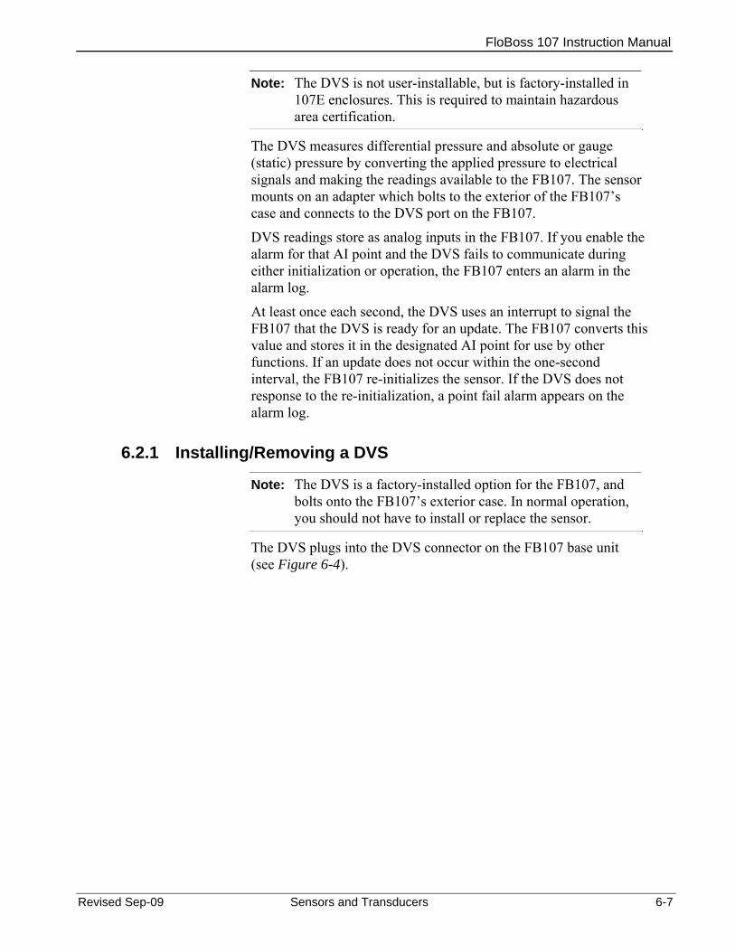
FloBoss 107 Instruction Manual
Revised Sep-09 Sensors and Transducers 6-7
Note: The DVS is not user-installable, but is factory-installed in 107E enclosures. This is required to maintain hazardous area certification.
The DVS measures differential pressure and absolute or gauge (static) pressure by converting the applied pressure to electrical signals and making the readings available to the FB107. The sensor mounts on an adapter which bolts to the exterior of the FB107’s case and connects to the DVS port on the FB107.
DVS readings store as analog inputs in the FB107. If you enable the alarm for that AI point and the DVS fails to communicate during either initialization or operation, the FB107 enters an alarm in the alarm log.
At least once each second, the DVS uses an interrupt to signal the FB107 that the DVS is ready for an update. The FB107 converts this value and stores it in the designated AI point for use by other functions. If an update does not occur within the one-second interval, the FB107 re-initializes the sensor. If the DVS does not response to the re-initialization, a point fail alarm appears on the alarm log.
6.2.1 Installing/Removing a DVS
Note: The DVS is a factory-installed option for the FB107, and bolts onto the FB107’s exterior case. In normal operation, you should not have to install or replace the sensor.
The DVS plugs into the DVS connector on the FB107 base unit (see Figure 6-4).
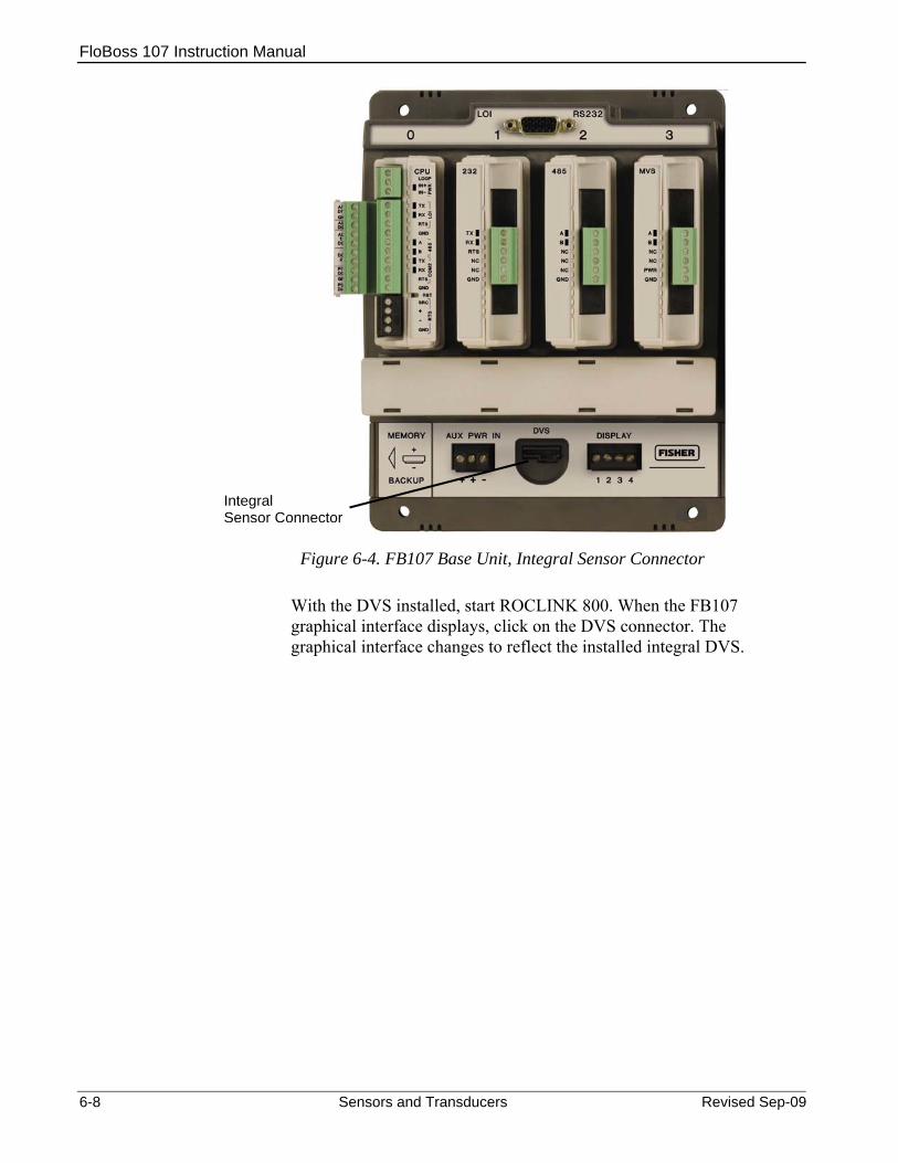
FloBoss 107 Instruction Manual
Figure 6-4. FB107 Base Unit, Integral Sensor Connector
With the DVS installed, start ROCLINK 800. When the FB107 graphical interface displays, click on the DVS connector. The graphical interface changes to reflect the installed integral DVS.
Integral Sensor Connector
6-8 Sensors and Transducers Revised Sep-09

FloBoss 107 Instruction Manual
Figure 6-5. FB107 Graphical Interface for DVS
The tabs—General, I/O Points, and Diagnostic—provide information (mostly read-only) on the DVS.
6.2.2 Physically Connecting a DVS Run piping from the meter run to the DVS. Both the static and differential pressures attach to female ¼-18 NPT connections on the bottom of the DVS. The FB107 is an upstream device: the static pressure line normally connects to the high pressure side (indicated by an H cast into the side of the DVS housing).
Caution To protect the DVS’s differential cell, open the bypass valve on the valve manifold PRIOR to isolating the sensor from the process. This keeps one side of the differential sensor from being subjected to high pressure while the other side has no applied pressure. This is required when you calibrate either differential or static pressure.
To protect the DVS’s differential cell, DO NOT close the bypass valve on the valve manifold until after process pressure has been reapplied. This keeps one side of the differential sensor from being subjected to high pressure while the other side has no applied pressure.
Revised Sep-09 Sensors and Transducers 6-9

FloBoss 107 Instruction Manual
6.2.3 Configuring a DVS
The DVS provides the FB107 with an analog input. To configure the input, access the I/O Points tab on the FB107 graphical interface and click on the configuration button.
ROCLINK 800 displays an Analog Input screen.
Figure 6-6. Analog Input
Refer to Section 7.2, Analog Input (AI) Configuration in the ROCLINK 800 Configuration Software User Manual (for FloBoss 107) (Form A6217) for complete instructions on using these screens to configure the AI.
6-10 Sensors and Transducers Revised Sep-09

FloBoss 107 Instruction Manual
6.3 Pressure Module (PM) Overview
Note: Pressure modules not user-installable, but are factory-installed in 107E enclosures. This is required to maintain hazardous area certification.
Figure 6-7. FB107 Enclosure with Optional LCD and Pressure Module
The Pressure module (PM) provides the FB107 with pressure inputs and pulse counts for AGA7 flow calculations with AGA8 compressibility. Each FB107 supports one PM, which has two components: a pulse counter and a pressure transducer.
LCD
PM module
When used with a rotary meter, the PM creates and measures electrical signals (pulses) from the rotary meter and raw pressure inputs from its pressure transducer. The module automatically interprets the direction of rotation, and has a resolution of 1000 pulses per revolution.
When used with a turbine, the pressure transducer in the PM measures pressure while a designated I/O module in the FB107 measures pulses from the turbine meter.
Note: Turbine pulse inputs must go to the PI of an I/O module, with a pre-amp to amplify the signal.
The primary inputs for AGA7 flow measurements are pulse input counts, static pressure, and temperature. Pulse input counts come from the rotary or turbine meter; static pressure (including auxiliary pressure) inputs come from the pressure transducers; and temperature readings come from an RTD probe. The FB107 reads inputs in the following sequence at the following frequencies:
Pulse counts are read once per second.
Static pressure is sampled once per second. Revised Sep-09 Sensors and Transducers 6-11

FloBoss 107 Instruction Manual
Temperature is sampled and linearized once per second.
6.3.1 Installing/Removing a Pressure Module
Note: The PM is a factory-installed option for the FB107, and is bolted onto the FB107’s exterior case. In normal operation, you should not have to install or replace the module.
The Pressure module connects through the DVS connector on the FB107 base unit (see Figure 6-8).
Figure 6-8. FB107 Base Unit, Integral Sensor Connector
With the PM module installed, you can start ROCLINK 800. When the FB107 graphical interface displays, click on the DVS connector. The graphical interface changes to reflect values for the installed PM.
Note: The ROCLINK 800 graphic labels the Pressure module as an “Integral PIM.”
Integral Sensor Connector
6-12 Sensors and Transducers Revised Sep-09
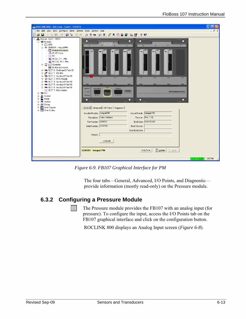
FloBoss 107 Instruction Manual
Figure 6-9. FB107 Graphical Interface for PM
The four tabs—General, Advanced, I/O Points, and Diagnostic—provide information (mostly read-only) on the Pressure module.
6.3.2 Configuring a Pressure Module
The Pressure module provides the FB107 with an analog input (for pressure). To configure the input, access the I/O Points tab on the FB107 graphical interface and click on the configuration button.
ROCLINK 800 displays an Analog Input screen (Figure 6-8).
Revised Sep-09 Sensors and Transducers 6-13

FloBoss 107 Instruction Manual
Figure 6-10. Analog Input
Refer to Section 7.2, Analog Input (AI) Configuration in the ROCLINK 800 Configuration Software User Manual (for FloBoss 107) (Form A6217) for complete instructions on using these screens to configure the AI.
6-14 Sensors and Transducers Revised Sep-09

FloBoss 107 Instruction Manual
Revised Sep-09 Troubleshooting 7-1
Chapter 7 – Troubleshooting
This chapter provides generalized guidelines for troubleshooting the FB107. Use the procedures in this chapter before you remove power, after you restore power, or if you disassemble the FB107.
The following tools are required for troubleshooting: A personal computer (PC) running Windows® 2000 (with Service Pack
2), Windows XP, or Windows Vista. ROCLINK 800 software. Flat-head (size 1/10 inch) screwdriver. Philips (size 0) screwdriver.
In This Chapter
7.1 General Guidelines .............................................................................7-1 7.2 Graphical User Interface (GUI) ...........................................................7-2 7.3 Checklists............................................................................................7-3
7.3.1 LEDs ......................................................................................7-3 7.3.2 Serial Communications..........................................................7-4 7.3.3 Inputs/Outputs .......................................................................7-4 7.3.4 Preserving Configuration and Log Data ................................7-5 7.3.5 ROCLINK 800 Configuration Software ..................................7-6 7.3.6 Powering Up ..........................................................................7-6 7.3.7 Multi-Variable Sensor (MVS) .................................................7-7 7.3.8 Resistance Temperature Detector (RTD)..............................7-7
7.4 Procedures..........................................................................................7-8 7.4.1 Resetting the FB107..............................................................7-8 7.4.2 Restarting and Reconfiguring the FB107 ..............................7-8 7.4.3 Troubleshooting Analog Inputs..............................................7-9 7.4.4 Troubleshooting Analog Outputs .........................................7-10 7.4.5 Troubleshooting Discrete Inputs..........................................7-11 7.4.6 Troubleshooting Discrete Outputs .......................................7-11 7.4.7 Troubleshooting Pulse Inputs ..............................................7-12 7.4.8 Troubleshooting RTD Inputs................................................7-12 7.4.9 Troubleshooting the Multi-Variable Sensor (MVS) ..............7-14 7.4.10 Troubleshooting the Enhanced Comm Module (ECM)........7-15 7.4.11 Troubleshooting the Dual Variable Sensor (DVS)...............7-15 7.4.12 Troubleshooting the Pressure Module (PM)........................7-16 7.4.13 Troubleshooting AI/DI ..........................................................7-16 7.4.14 Troubleshooting the Discrete Output Relay (DOR) .............7-17
7.1 General Guidelines When you are attempting to diagnose a problem with a FB107:
Write down what steps you have taken. Save the configuration and log data (refer to Section 7.3.4,
Preserving Configuration and Log Data). Note the order in which you remove components.

FloBoss 107 Instruction Manual
Note the orientation of the components before you alter or remove them.
Read and follow all cautions in this manual. When you finish troubleshooting, perform the restart procedure in Section 7.4.2, Restarting and Reconfiguring the FB107.
Caution Failure to exercise proper electrostatic discharge precautions, such as wearing a grounded wrist strap may reset the processor or damage electronic components, resulting in interrupted operations.
If the FB107 is used in a control application, ensure the system is off-line.
7.2 Graphical User Interface (GUI) The FB107’s graphical user interface (GUI) provides visual clues to help you diagnose problems.
Once you successfully log onto ROCLINK 800 and connect to the FB107, the GUI displays (see Figure 7-1).
Alarm (Yellow) Integrity Alert
(Red)
Figure 7-1. FB107 GUI
7-2 Troubleshooting Revised Sep-09

FloBoss 107 Instruction Manual
Revised Sep-09 Troubleshooting 7-3
The I in a red box indicates an integrity alert. The A in a yellow box indicates an alarm. This example screen shows a red integrity alert on the CPU module’s I/O assembly, and both an integrity alert and an alarm on the I/O module in slot 2. Note that the screen below the FB107 image provides additional information on the alerts or alarms.
Situations that could cause integrity alerts include:
Communications failures: A module has failed or has been removed.
Note: This error occurs on I/O modules and MVS modules.
Module mismatch: The CPU expected to see one kind of module and you actually installed another. Alternately, the installed module (which is saved to the configuration file) does not match the module physically installed in the FB107.
I/O points are out of range: For example, the AI point default A/D counts are 643 to 3220. If the AI is open and the FB107 reads 0 A/D counts, the FB107 generates an integrity alert.
Integrity alerts are typically related to hardware. Alarms are typically related to user-defined configurations. For more information on the FB107 GUI, refer to the ROCLINK 800 Configuration Software User Manual (for FloBoss 107) (Form A6217).
7.3 Checklists This section provides brief topical checklists.
7.3.1 LEDs If the LEDs do not display on the CPU or the modules: Verify the CPU power input is a minimum of 8 volts dc. Ensure power is applied to the FB107. Verify the wiring connections at PWR+ and PWR−. Verify the wiring connections at the power source. Test and reseat the terminal blocks. Verify all module power inputs are adequate. Verify the input polarity is correct. Ensure the module is fully seated in the backplane.
Note: The Power In+ LED should be the only LED always on. All other LEDs flash only during communication. A flashing power LED indicates the FB107 is in power savings mode.

FloBoss 107 Instruction Manual
7.3.2 Serial Communications If you are experiencing troubles with a serial communications connection (LOI, EIA-232, or EIA-485):
Ensure that power is applied to the FB107. Verify the wiring connections at PWR+ and PWR−. Verify the wiring connections at the power source. Verify the wiring connections at TX, RX, A, B, and GND. Refer to
Chapter 5, Communications.
Note: The Power In+ LED should be the only LED always on. All other LEDs flash only during communication. A flashing power LED indicates the FB107 is in power savings mode.
Verify the communication port settings in ROCLINK 800 (ROC > Comm Ports).
Note: You must perform a power re-start to allow ROCLINK 800 to identify the module.
7.3.3 Inputs/Outputs If you are experiencing troubles with an I/O point (analog input, analog output, discrete input, discrete output, pulse input, or RTD):
Ensure that power is applied to the FB107. Verify the wiring connections at PWR+ and PWR−. Verify the wiring connections at the power source. Verify how the channel is configured using ROCLINK 800 software
(Configure > I/O). If the configuration looks correct, then simulate an input (within the
range of the input) or force the production of an output using ROCLINK 800 software:
AI +
AO —
If I/O does functions correctly, determine if the problem is with the field device or the loop power:
7-4 Troubleshooting Revised Sep-09

FloBoss 107 Instruction Manual
If the types of I/O available for configuration do not match the type
of I/O wired to the terminations, check the I/O Setup screen (refer to Chapter 4, Inputs and Outputs).
If an input channel is in question, you may be able to use one of the outputs (known to be in working order) to simulate the required input. Likewise, if an output channel is in question, you may able to connect it to a working input channel and check the results.
Notes: FB107 modules do not contain any user-serviceable parts.
You must perform a power restart to allow ROCLINK 800 to identify the module.
7.3.4 Preserving Configuration and Log Data Before you power down the FB107 to repair or upgrade, to remove or add a component, or to troubleshoot, you should preserve the FB107 configuration and log data held in RAM.
Caution When installing equipment in a hazardous area, ensure that all components are approved for use in such areas. Check the product labels. Change components only in an area known to be non-hazardous. Performing these procedures in a hazardous area could result in personal injury or property damage.
To avoid circuit damage when working inside the unit, use appropriate electrostatic discharge precautions, such as wearing a grounded wrist strap.
1. Connect to ROCLINK 800 and connect to the FB107.
2. Ensure that the configuration is saved in flash memory. Select ROC > Flags > Save to Flash Memory. This saves all configuration settings, including the current states of the ROC Flags and calibration values.
3. Select ROC > Collect Data.
4. Type the desired File name for the backup file, or use the default.
Revised Sep-09 Troubleshooting 7-5

FloBoss 107 Instruction Manual
7-6 Troubleshooting Revised Sep-09
5. Click Save.
6. Click OK. This saves event logs, alarm logs, report data, and history, but not non-EFM history points. You can specify your own file name and path if desired.
7. Select File > Save Configuration. The Save As dialog box appears.
8. Enter a File name.
9. Click Save. ROCLINK 800 saves the file in the default directory C:/Program Files/ROCLINK 800/Data unless you changed the directory.
7.3.5 ROCLINK 800 Configuration Software If you are experiencing problems with the FB107 that appear to be software-related, try resetting the FB107.
Note: Download history, events, and alarm logs prior to a restart. Before you attempt any type of reset, back up your configuration and log data. Refer to Preserving Configuration and Log Data.
Use a warm start to restart without losing configuration or log data. To perform a warm start, open ROCLINK 800 software, connect to the FB107 and select ROC > Flags. Click Warm Start on the Flags screen.
Use a cold start to restart without a portion of the configuration, log data, or programming that may be the trouble. To perform a cold start, open ROCLINK 800 software, connect to the FB107 and select ROC > Flags. Click Cold Start on the Flags screen.
Following a warm start and a cold start, if you still cannot connect and you cannot connect to the FB107 using the LOI port, use the reset switch on the FB107’s CPU module and cycle power to restore the LOI communications parameters to factory defaults. Refer to Section 7.4.1, Resetting the FB107.
Note: If these methods do not solve the problem, contact your local sales representative.
7.3.6 Powering Up If you are experiencing trouble with powering up the FB107:
Ensure that power is applied to the FB107.
Verify the wiring connections at PWR+ and PWR−.
Verify the wiring connections at the power source.

FloBoss 107 Instruction Manual
Revised Sep-09 Troubleshooting 7-7
Verify the input voltage, which should be a minimum of 8 volts dc (refer to Chapter 3, Power Connections).
Note: If these methods do not solve the problem, contact your local sales representative.
7.3.7 Multi-Variable Sensor (MVS) If you are experiencing trouble with a MVS point:
Review Section 6.1, Multi-Variable Sensor (MVS) Module Overview in Chapter 6, Sensors and Transducers.
Use ROCLINK 800 to see how the channel is configured.
If more than one MVS is connected to the FB107, use the Multi-Variable Sensor screen (Configure > I/O > MVS Sensor) to ensure that each MVS has a unique address.
7.3.8 Resistance Temperature Detector (RTD) If you are experiencing troubles with the RTD:
Use ROCLINK 800 to verify that the on-board RTD point is configured as point number AI3 (RTD=AI3).
If the configuration looks correct, then use ROCLINK 800 to produce a simulated input (within the range of the input) according to the following values:
84Ω –40°C –40°F 100Ω 0°C 32°F 150Ω 130°C 267°F 200Ω 267°C 512°F 250Ω 408°C 767°F
Note: These values are approximations only. Do not use these values
to calibrate the device.
Verify that the wiring to the RTD terminations is correct. Refer to Chapter 4, Input and Outputs.
Verify that the user-supplied RTD probe is not faulty. Refer to the instructions that accompanied the RTD probe.
FloBoss 107 Instruction Manual
7.4 Procedures This section presents step-by-step produces to help you troubleshoot.
7.4.1 Resetting the FB107 You reset the FB107 to perform a type of cold start that re-establishes a known operating point and loads the factory defaults (19,200 baud rate, 8 data bits, no parity, and 1 stop bit) into the communication ports. The reset (RST) switch is located on the CPU module, just above the RTD terminal block.
This cold start does not include any of the clearing options available in a cold start performed using ROCLINK 800 software.
Note: This type of reset restores the communications ports to the factory configuration defaults. Some user-entered configuration parameters may be lost. Therefore, back up any required data before performing this reset.
1. Refer to Section 7.3.4, Preserving Configuration and Log Data.
2. Remove power from the FB107.
3. Depress and hold down the reset (RST) switch.
4. While pressing the RST switch, reconnect the power to the FB107.
5. After the power LED flashes twice, release the RST switch.
6. Refer to Section 7.4.2, Restarting and Reconfiguring the FB107.
7.4.2 Restarting and Reconfiguring the FB107 After removing power to the FB107 and performing maintenance or repair, perform the following steps to start your FB107 and reconfigure your data. The procedure assumes you are using ROCLINK 800.
Caution Ensure all input devices, output devices, and processes remain in a safe state upon restoring power. An unsafe state could result in property damage.
When installing equipment in a hazardous area, ensure that all components are approved for use in such areas. Check the product labels. Change components only in an area known to be non-hazardous. Performing these procedures in a hazardous area could result in personal injury or property damage.
1. Reconnect power to the FB107 unit by inserting the PWR+ / PWR− power terminal block.
2. Launch ROCLINK 800, log in, and connect to the FB107.
7-8 Troubleshooting Revised Sep-09
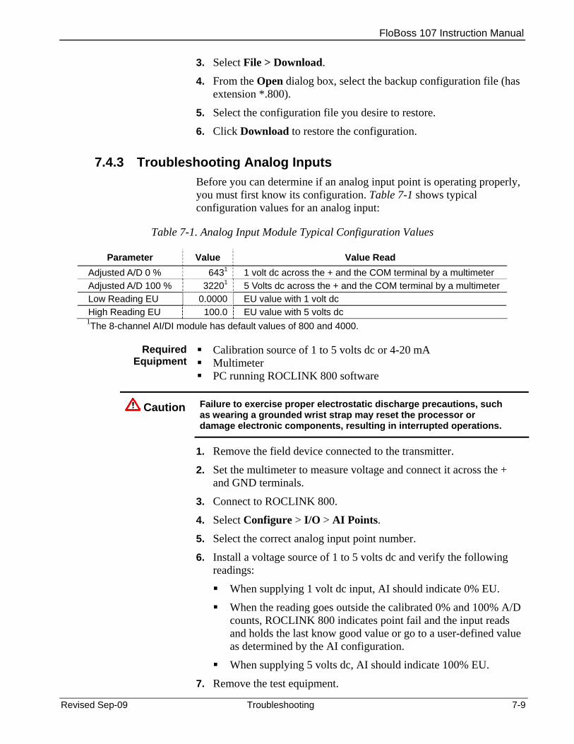
FloBoss 107 Instruction Manual
3. Select File > Download.
4. From the Open dialog box, select the backup configuration file (has extension *.800).
5. Select the configuration file you desire to restore.
6. Click Download to restore the configuration.
7.4.3 Troubleshooting Analog Inputs Before you can determine if an analog input point is operating properly, you must first know its configuration. Table 7-1 shows typical configuration values for an analog input:
Table 7-1. Analog Input Module Typical Configuration Values
Parameter Value Value Read Adjusted A/D 0 % 6431 1 volt dc across the + and the COM terminal by a multimeter Adjusted A/D 100 % 32201 5 Volts dc across the + and the COM terminal by a multimeter Low Reading EU 0.0000 EU value with 1 volt dc High Reading EU 100.0 EU value with 5 volts dc 1The 8-channel AI/DI module has default values of 800 and 4000.
Required
Equipment Calibration source of 1 to 5 volts dc or 4-20 mA Multimeter PC running ROCLINK 800 software
Caution Failure to exercise proper electrostatic discharge precautions, such as wearing a grounded wrist strap may reset the processor or damage electronic components, resulting in interrupted operations.
1. Remove the field device connected to the transmitter.
2. Set the multimeter to measure voltage and connect it across the + and GND terminals.
3. Connect to ROCLINK 800.
4. Select Configure > I/O > AI Points.
5. Select the correct analog input point number.
6. Install a voltage source of 1 to 5 volts dc and verify the following readings:
When supplying 1 volt dc input, AI should indicate 0% EU.
When the reading goes outside the calibrated 0% and 100% A/D counts, ROCLINK 800 indicates point fail and the input reads and holds the last know good value or go to a user-defined value as determined by the AI configuration.
When supplying 5 volts dc, AI should indicate 100% EU.
7. Remove the test equipment.
Revised Sep-09 Troubleshooting 7-9
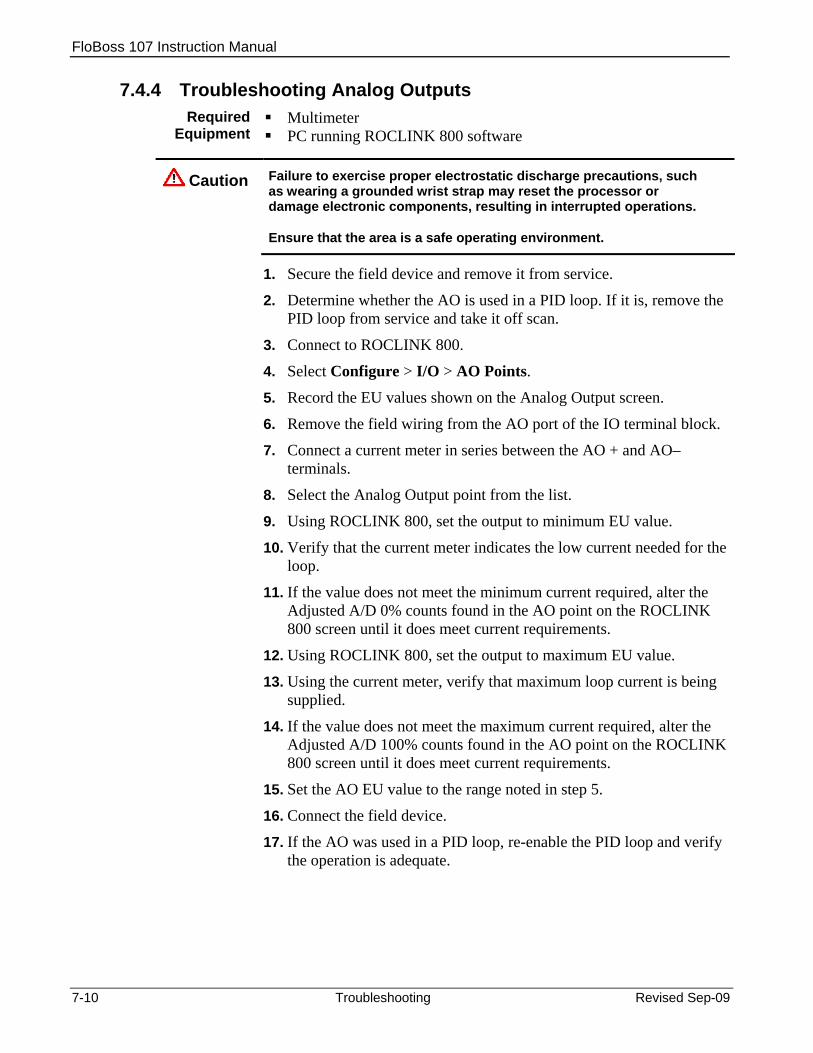
FloBoss 107 Instruction Manual
7.4.4 Troubleshooting Analog Outputs Required
Equipment Multimeter PC running ROCLINK 800 software
Caution Failure to exercise proper electrostatic discharge precautions, such as wearing a grounded wrist strap may reset the processor or damage electronic components, resulting in interrupted operations.
Ensure that the area is a safe operating environment.
1. Secure the field device and remove it from service.
2. Determine whether the AO is used in a PID loop. If it is, remove the PID loop from service and take it off scan.
3. Connect to ROCLINK 800.
4. Select Configure > I/O > AO Points.
5. Record the EU values shown on the Analog Output screen.
6. Remove the field wiring from the AO port of the IO terminal block.
7. Connect a current meter in series between the AO + and AO–terminals.
8. Select the Analog Output point from the list.
9. Using ROCLINK 800, set the output to minimum EU value.
10. Verify that the current meter indicates the low current needed for the loop.
11. If the value does not meet the minimum current required, alter the Adjusted A/D 0% counts found in the AO point on the ROCLINK 800 screen until it does meet current requirements.
12. Using ROCLINK 800, set the output to maximum EU value.
13. Using the current meter, verify that maximum loop current is being supplied.
14. If the value does not meet the maximum current required, alter the Adjusted A/D 100% counts found in the AO point on the ROCLINK 800 screen until it does meet current requirements.
15. Set the AO EU value to the range noted in step 5.
16. Connect the field device.
17. If the AO was used in a PID loop, re-enable the PID loop and verify the operation is adequate.
7-10 Troubleshooting Revised Sep-09
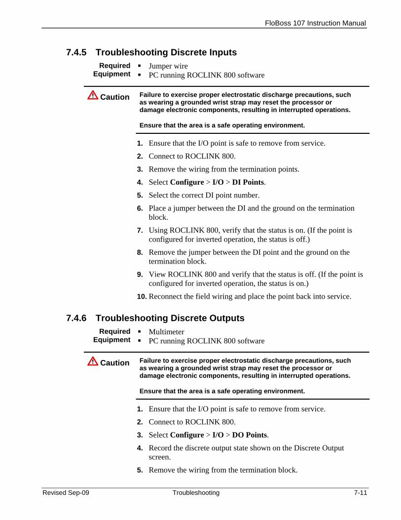
FloBoss 107 Instruction Manual
7.4.5 Troubleshooting Discrete Inputs Required
Equipment Jumper wire PC running ROCLINK 800 software
Caution Failure to exercise proper electrostatic discharge precautions, such as wearing a grounded wrist strap may reset the processor or damage electronic components, resulting in interrupted operations.
Ensure that the area is a safe operating environment.
1. Ensure that the I/O point is safe to remove from service.
2. Connect to ROCLINK 800.
3. Remove the wiring from the termination points.
4. Select Configure > I/O > DI Points.
5. Select the correct DI point number.
6. Place a jumper between the DI and the ground on the termination block.
7. Using ROCLINK 800, verify that the status is on. (If the point is configured for inverted operation, the status is off.)
8. Remove the jumper between the DI point and the ground on the termination block.
9. View ROCLINK 800 and verify that the status is off. (If the point is configured for inverted operation, the status is on.)
10. Reconnect the field wiring and place the point back into service.
7.4.6 Troubleshooting Discrete Outputs Required
Equipment Multimeter PC running ROCLINK 800 software
Caution Failure to exercise proper electrostatic discharge precautions, such as wearing a grounded wrist strap may reset the processor or damage electronic components, resulting in interrupted operations.
Ensure that the area is a safe operating environment.
1. Ensure that the I/O point is safe to remove from service.
2. Connect to ROCLINK 800.
3. Select Configure > I/O > DO Points.
4. Record the discrete output state shown on the Discrete Output screen.
5. Remove the wiring from the termination block.
Revised Sep-09 Troubleshooting 7-11

FloBoss 107 Instruction Manual
6. Select the correct DO point number.
7. Connect an ohm meter from the DO+ to the DO-.
8. When the DO is off, the ohm meter should indicate an open circuit.
9. Using ROCLINK 800, set the DO to the on state.
10. Verify that the ohm meter indicates less than 10 ohms.
11. Using ROCLINK 800, set the DO to the off state.
12. Reconnect the DO field wiring.
13. Set the DO to the state recorded in step 4.
7.4.7 Troubleshooting Pulse Inputs Required
Equipment Pulse Generator Voltage Generator Frequency Counter Jumper wire PC running ROCLINK 800 software
Caution Failure to exercise proper electrostatic discharge precautions, such as wearing a grounded wrist strap may reset the processor or damage electronic components, resulting in interrupted operations.
To verify 10 Khz operation:
1. Connect to ROCLINK 800.
2. Select Configure > I/O > PI Points.
3. Select the correct pulse input point number.
4. Connect a pulse generator having sufficient output to drive the module to terminals + and GND. The pulse generator must synthesize a square wave signal of 50% for every cycle.
5. Connect a frequency counter across terminals + and GND.
6. Set the pulse generator to a value equal to, or less than 10 KHz.
7. Set the frequency counter to count pulses.
8. Verify, using ROCLINK 800 software, that the count read by the counter and the FB107 are the same.
9. Remove the test equipment, and reconnect the field device.
7.4.8 Troubleshooting RTD Inputs The RTD input is similar in operation to an analog input and uses the same troubleshooting and repair procedures.
Required Equipment
Multimeter PC running ROCLINK 800 software
7-12 Troubleshooting Revised Sep-09
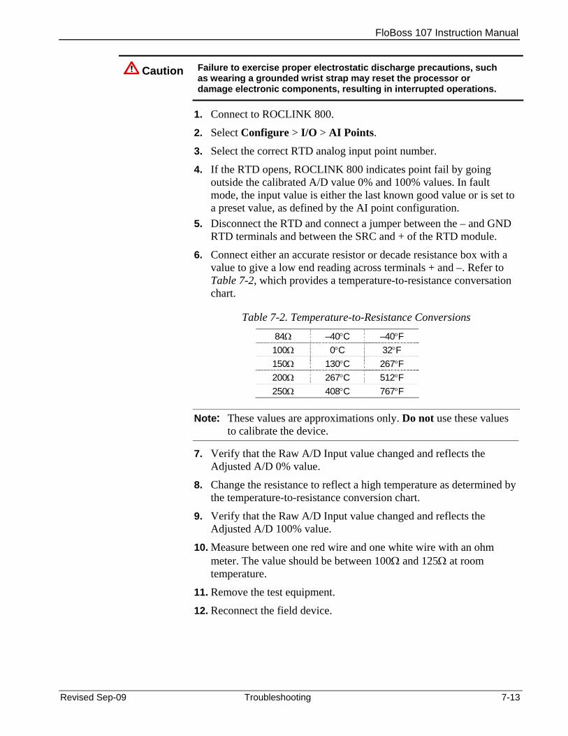
FloBoss 107 Instruction Manual
Caution Failure to exercise proper electrostatic discharge precautions, such as wearing a grounded wrist strap may reset the processor or damage electronic components, resulting in interrupted operations.
1. Connect to ROCLINK 800.
2. Select Configure > I/O > AI Points.
3. Select the correct RTD analog input point number.
4. If the RTD opens, ROCLINK 800 indicates point fail by going outside the calibrated A/D value 0% and 100% values. In fault mode, the input value is either the last known good value or is set to a preset value, as defined by the AI point configuration.
5. Disconnect the RTD and connect a jumper between the – and GND RTD terminals and between the SRC and + of the RTD module.
6. Connect either an accurate resistor or decade resistance box with a value to give a low end reading across terminals + and –. Refer to Table 7-2, which provides a temperature-to-resistance conversation chart.
Table 7-2. Temperature-to-Resistance Conversions
84Ω –40°C –40°F 100Ω 0°C 32°F 150Ω 130°C 267°F 200Ω 267°C 512°F 250Ω 408°C 767°F
Note: These values are approximations only. Do not use these values to calibrate the device.
7. Verify that the Raw A/D Input value changed and reflects the Adjusted A/D 0% value.
8. Change the resistance to reflect a high temperature as determined by the temperature-to-resistance conversion chart.
9. Verify that the Raw A/D Input value changed and reflects the Adjusted A/D 100% value.
10. Measure between one red wire and one white wire with an ohm meter. The value should be between 100Ω and 125Ω at room temperature.
11. Remove the test equipment.
12. Reconnect the field device.
Revised Sep-09 Troubleshooting 7-13
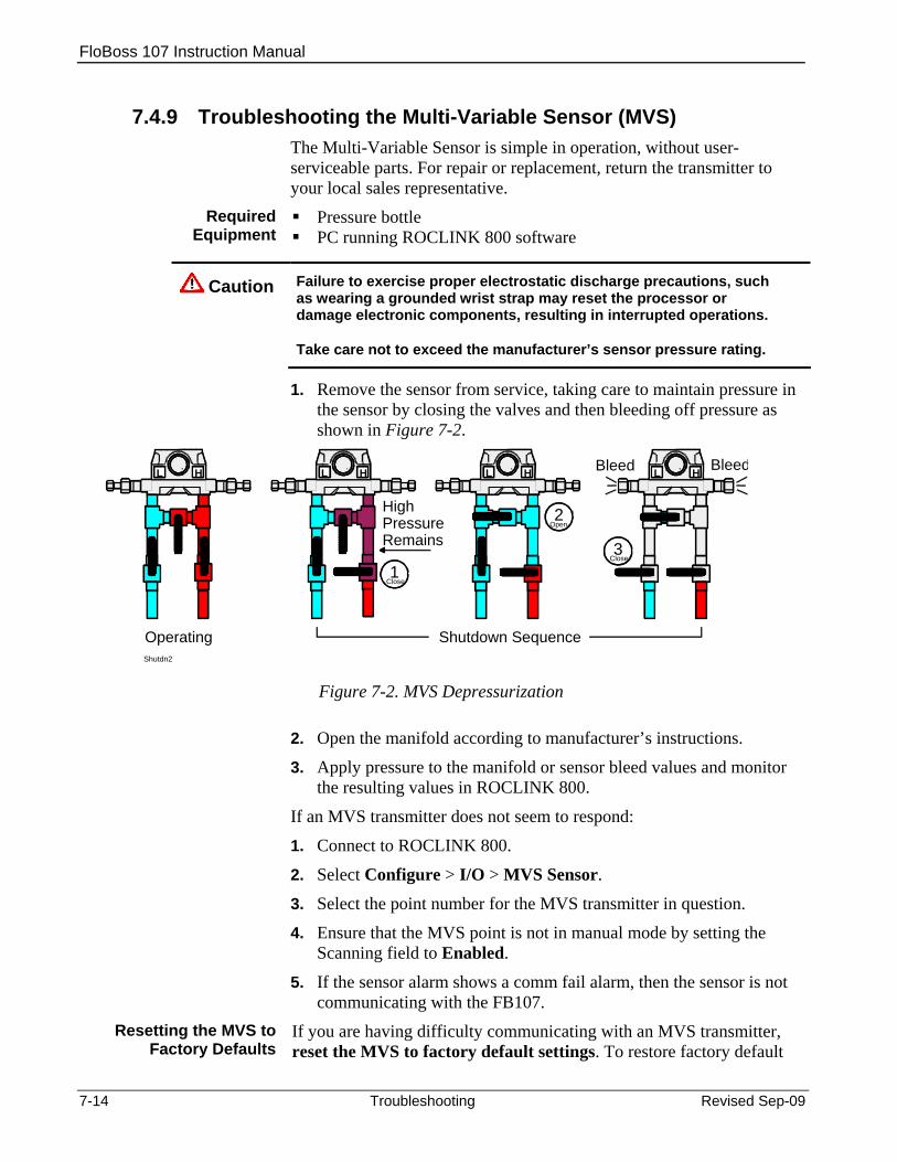
FloBoss 107 Instruction Manual
7.4.9 Troubleshooting the Multi-Variable Sensor (MVS) The Multi-Variable Sensor is simple in operation, without user-serviceable parts. For repair or replacement, return the transmitter to your local sales representative.
Required Equipment
Pressure bottle PC running ROCLINK 800 software
Caution Failure to exercise proper electrostatic discharge precautions, such as wearing a grounded wrist strap may reset the processor or damage electronic components, resulting in interrupted operations.
Take care not to exceed the manufacturer’s sensor pressure rating.
1. Remove the sensor from service, taking care to maintain pressure in the sensor by closing the valves and then bleeding off pressure as shown in Figure 7-2.
1Close
Shutdn2
L H
2Open
L H
3Close
L H
HighPressureRemains
Bleed BleedL H
Operating Shutdown Sequence
Figure 7-2. MVS Depressurization
2. Open the manifold according to manufacturer’s instructions.
3. Apply pressure to the manifold or sensor bleed values and monitor the resulting values in ROCLINK 800.
If an MVS transmitter does not seem to respond:
1. Connect to ROCLINK 800.
2. Select Configure > I/O > MVS Sensor.
3. Select the point number for the MVS transmitter in question.
4. Ensure that the MVS point is not in manual mode by setting the Scanning field to Enabled.
5. If the sensor alarm shows a comm fail alarm, then the sensor is not communicating with the FB107.
Resetting the MVS to Factory Defaults
If you are having difficulty communicating with an MVS transmitter, reset the MVS to factory default settings. To restore factory default
7-14 Troubleshooting Revised Sep-09

FloBoss 107 Instruction Manual
settings in an MVS: 1. Connect the FB107 to a PC running ROCLINK 800.
2. Select Utilities > MVS Calibration.
3. Click Set Back to Factory Defaults.
4. Click Yes.
Notes:
If you are troubleshooting an RTD an MVS point uses, refer to Section 7.4.8, Troubleshooting RTD Inputs.
You must perform a power restart in order to have ROCLINK 800 identify the module.
7.4.10 Troubleshooting the Enhanced Comm Module (ECM) The ECM does not have user-serviceable parts. If the Ethernet port does not seem to function, try the USB port. Alternately, if the USB port does not seem to function, try the Ethernet port. If neither port seems to work, return the module to your local sales representative for repair or replacement.
When using ROCLINK 800, if the ECM displays a red “I” (integrity) error, that indicates a loss of communications. Immediately increase the clock speed (using the Advanced tab on the CPU module) to 14 or 29 MHz.
7.4.11 Troubleshooting the Dual Variable Sensor (DVS) The Dual Variable Sensor is simple in operation, without user-serviceable parts.
Required Equipment
Pressure bottle PC running ROCLINK 800 software
Caution Failure to exercise proper electrostatic discharge precautions, such as wearing a grounded wrist strap may reset the processor or damage electronic components, resulting in interrupted operations.
Take care not to exceed the manufacturer’s sensor pressure rating.
1. Remove the sensor from service, taking care to maintain pressure in the sensor by closing the valves and then bleeding off pressure as shown in Figure 7-3.
Revised Sep-09 Troubleshooting 7-15

FloBoss 107 Instruction Manual
1Close
Shutdn2
L H
2Open
L H
3Close
L H
HighPressureRemains
Bleed BleedL H
Operating Shutdown Sequence
Figure 7-3. DVS Depressurization
2. Open the manifold according to manufacturer’s instructions.
3. Apply pressure to the manifold or sensor bleed values and monitor the resulting values in ROCLINK 800.
7.4.12 Troubleshooting the Pressure Module (PM) The Pressure module (PM) provides the FB107 with pressure inputs and pulse counts. The PM has a pulse counter and a pressure transducer.
Required Equipment
Multimeter PC running ROCLINK 800 software
Caution Failure to exercise proper electrostatic discharge precautions, such as wearing a grounded wrist strap may reset the processor or damage electronic components, resulting in interrupted operations.
1. Remove the module from service.
2. Apply pressure to the PIM (not to exceed the manufacturer’s pressure rating).
Note: The pulses for the module come into the FB107 either through the on-board (CPU-based) I/O or an auxiliary I/O module in slots 1 through 7.
3. Start ROCLINK 800 and monitor the PI points as you rapidly short the PI+ channel to common. If the module is functioning correctly, the pulse count should increment and you should be able to monitor the frequency in ROCLINK 800.
7.4.13 Troubleshooting AI/DI This module provides eight AI or DI signals. Troubleshooting depends on whether you have selected AI or DI wiring.
Required Equipment
Multimeter Digitial voltmeter
7-16 Troubleshooting Revised Sep-09
FloBoss 107 Instruction Manual
PC running ROCLINK 800 software
Caution Failure to exercise proper electrostatic discharge precautions, such as wearing a grounded wrist strap may reset the processor or damage electronic components, resulting in interrupted operations.
As AI 1. Remove the module from service. 2. Using a digital voltmeter, measure the “Loop” connector to “Gnd”
connector. It should measure 24 V dc.
3. Put a known 1-5 V dc from the input to Gnd on any AI-configured channel and monitor the voltage in ROCLINK 800.
As DI 1. Remove the module from service. 2. Short the DI+ to DI- and monitor the on/off toggling in ROCLINK
800.
7.4.14 Troubleshooting the Discrete Output Relay (DOR) Required
Equipment Ohm meter PC running ROCLINK 800 software
Caution Failure to exercise proper electrostatic discharge precautions, such as wearing a grounded wrist strap may reset the processor or damage electronic components, resulting in interrupted operations.
1. Remove the module from service.
2. Disconnect the field terminal block and replace it.
3. Place an ohm meter on the contacts.
4. Connect to ROCLINK 800 and toggle the module on and off, monitoring the ohm meter to verify toggle status.
Revised Sep-09 Troubleshooting 7-17

FloBoss 107 Instruction Manual
7-18 Troubleshooting Revised Sep-09
[This page is intentionally left blank]

FloBoss 107 Instruction Manual
Revised Sep-09 Glossary A-1
Appendix A – Glossary
Note: This is a generalized glossary of terms. Not all the terms may necessarily correspond to the particular device or software described in this manual. For that reason, the term “ROC” is used to identify all varieties of Remote Operations Controllers (including ROC800-Series, ROC300-Series, FloBoss™ 103/104/, FloBoss 107, FloBoss 503/504, and FloBoss 407 units).
A A/D Analog to Digital signal conversion. ABS Acrylonitrile Butadiene Styrene. ADC Analog to Digital Converter. Used to convert analog inputs (AI) to a format the flow
computer can use. AGA American Gas Association. A professional organization that oversees the AGA3
(orifice), AGA5 (heating value), AGA7 (turbine), AGA8 (compressibility), and AGA11 (ultrasonic) gas flow calculation standards. See http://www.aga.org.
AWG American Wire Gauge. AI Analog Input. AO Analog Output. Analog Analog data is represented by a continuous variable, such as an electrical current
signal. Annubar A device that uses Pitot tubes to measure the gas flow rate within a pipeline. The gas
volume is calculated from the difference between the flowing pressure and the static pressure of the gas.
AP Absolute Pressure. API American Petroleum Institute. See http://www.api.org. Area A user-defined grouping of database entities. ASCII American (National) Standard Code for Information Interchange. Attribute A parameter that provides information about an aspect of a database point. For
example, the alarm attribute is an attribute that uniquely identifies the configured value of an alarm.
B BMV Base Multiplier Value, used in AGA7 (turbine) calculations. BPS Bits Per Second, associated with baud rate. BTU British Thermal Unit, a measure of heat energy. Built-in I/O I/O channels that are fabricated into the ROC and do not require a separate option.
Also called “on-board” I/O.
C C1D2 Class 1, Division 2 hazardous area CMOS Complementary Metal Oxide Semiconductor, a type of microprocessor used in a ROC. Coil Digital output, a bit to be cleared or set.

FloBoss 107 Instruction Manual
A-2 Glossary Revised Sep-09
COL Ethernet Packet Collision. COM Communications port on a personal computer (PC). COMM Communications port on a ROC used for host communications. Comm Module Module that plugs into a ROC to provide a channel for communications via a specified
communications protocol, such as EIA-485 (RS-485) or HART. CF Compare Flag; stores the Signal Value Discrete (SVD). Configuration Refers either to the process of setting up the software for a given system or the result
of performing this process. The configuration activity includes editing the database, building schematic displays and reports, and defining user calculations. Typically, the software setup of a device that can often be defined and changed. Can also mean the hardware assembly scheme.
Configuration Tree
In ROCLINK 800, the graphical display that appears when a configuration file opens. It is a hierarchical branching (“tree-style”) method for navigating within the configuration screens.
CPU Central Processing Unit. CRC Cyclical Redundancy Check error checking. Crosstalk The amount of signal that crosses over between the receive and transmit pairs, and
signal attenuation, which is the amount of signal loss encountered on the Ethernet segment.
CSA Canadian Standards Association. See http://www.csa.ca. CSMA/CD Carrier Sense Multiple Access with Collision Detection. CTS Clear to Send modem communications signal.
D D/A Digital to Analog signal conversion. DB Database. dB Decibel. A unit for expressing the ratio of the magnitudes of two electric signals on a
logarithmic scale. DCD Data Carrier Detect modem communications signal. In addition, Discrete Control
Device – A discrete control device energizes a set of discrete outputs for a given setpoint and matches the desired result against a set of discrete inputs (DI).
DCE Data Communication Equipment. Deadband A value that is an inactive zone above the low limits and below the high limits. The
purpose of the deadband is to prevent a value (such as an alarm) from being set and cleared continuously when the input value is oscillating around the specified limit. This also prevents the logs or data storage location from being over-filled with data.
Device Directory
In ROCLINK 800, the graphical display that allows navigation through the PC Comm Ports and ROC Comm Ports setup screen.
DI Discrete Input. Discrete Input or output that is non-continuous, typically representing two levels (such as on/off). DMM Digital multimeter. DO Discrete Output. Download The process of sending data, a file, or a program from a PC to a ROC. DP Differential Pressure. DSR Data Set Ready modem communications signal. DTE Data Terminal Equipment. DTR Data Terminal Ready modem communications signal. Duty Cycle Proportion of time during a cycle that a device is activated. A short duty cycle

FloBoss 107 Instruction Manual
Revised Sep-09 Glossary A-3
conserves power for I/O channels, radios, and so on. DVM Digital voltmeter. DVS Dual-Variable Sensor. A device that provides static and differential pressure inputs to a
ROC.
E EEPROM Electrically Erasable Programmable Read-Only Memory, a form of permanent memory
on a ROC. EFM Electronic Flow Metering or Measurement. EIA-232 (RS-232)
Serial Communications Protocol using three or more signal lines, intended for short distances. Concerning RS232D and RS232C, the letters C or D refer to the physical connector type. D specifies the RJ-11 connector where a C specifies a DB25 type connector.
EIA-422 (RS-422)
Serial Communications Protocol using four signal lines.
EIA-485 (RS-485)
Serial Communications Protocol requiring only two signal lines. Can allow up to 32 devices to be connected together in a daisy-chained fashion.
EMF Electro-Motive Force. EMI Electro-Magnetic Interference. ESD Electro-Static Discharge. EU Engineering Units. Units of measure, such as MCF/DAY.
F FCC Federal Communications Commission. See http://www.fcc.gov. FET Field Effect Transmitter. Firmware Internal software that is factory-loaded into a form of ROM. In a ROC, the firmware
supplies the software used for gathering input data, converting raw input data values, storing values, and providing control signals.
FlashPAC module
ROM and RAM module for a ROC300-Series unit that contains the operating system, applications firmware, and communications protocol.
Flash ROM A type of read-only memory that can be electrically re-programmed. It is a form of permanent memory (requires no backup power). Also called Flash memory.
FloBoss A microprocess-based device that provides flow calculations, remote monitoring, and remote control. A FloBoss is a type of ROC.
FM Factory Mutual. Force Manually write an ON/OFF, True/False, or 1/0 value to a coil. FPV Compressibility Factor. FSK Frequency Shift Keypad. FST Function Sequence Table, a type of user-written program in a high-level language
designed by Emerson Process Management’s Flow Computer Division. Ft Foot or feet.
G GFA Ground Fault Analysis. GND Electrical ground, such as used by the ROC’s power supply. GP Gauge Pressure.
FloBoss 107 Instruction Manual
A-4 Glossary Revised Sep-09
H HART Highway Addressable Remote Transducer. Holding Register
Modbus term for an analog output number value to be read.
Hw Differential pressure. Hz Hertz.
I, J IC Integrated Circuit. Also, Industry Canada (more recently known as Measurement
Canada), an organization that grants custody transfer approvals on certain ROC units. ID Identification. IEC Industrial Electrical Code or International Electrotechnical Commission. See
http://www.iec.ch. IEEE Institute of Electrical and Electronic Engineers. A professional organization that, in
conjunction with the International Standards Organization (ISO), establishes and maintains the Open System Interconnection (OSI) reference model and an international standard for the organization of local area networks (LANs). Refer to http://www.ieee.org.
IMV Integral Multiplier Value, used in AGA3 (orifice) calculations. Input Digital input, a bit to be read. Input Register Input numeric value to be read. Local Port Also LOI; the serial EIA-232 (RS-232) port on the ROC through which local
communications are established, typically for configuration software running on a PC. I/O Input/Output. I/O Module Module that plugs into an I/O slot on a ROC to provide an I/O channel. IRQ Interrupt Request. Hardware address oriented. ISO International Standards Organization. See http://www.iso.ch. IV Integral Value.
K KB Kilobytes. KHz KiloHertz.
L LCD Liquid Crystal Display. LDP Local Display Panel, a display-only device that plugs into ROC300 (via a parallel
interface cable) used to access information stored in the ROC. LED Light-Emitting Diode. Logical Number The point number the ROC and ROC Plus protocols use for I/O point types are based
on a physical input or output with a terminal location; the point numbers for all other point types are “logical” and are simply numbered in sequence.
LNK Ethernet has linked. LOI Local Operator Interface (or Local Port). Refers to the serial EAI-232 (RS-232) port on
the ROC through which local communications are established, typically for configuration software running on a PC.
LPM Lightning Protection Module; a device that provides lightning and power surge protection for ROCs.

FloBoss 107 Instruction Manual
Revised Sep-09 Glossary A-5
LRC Longitudinal Redundancy Checking error checking.
M m Meter. mA Milliamp(s); one thousandth of an ampere. MAC Address Media Access Control Address; a hardware address that uniquely identifies each node
of a network. Manual mode For a ROC, indicates that the I/O scanning has been disabled. MAU Medium Attachment Unit. MCU Master Controller Unit. Modbus A popular device communications protocol developed by Gould-Modicon. MPU Micro-Processor Unit. mm Millimeter. MMBTU Million British Thermal Units. msec Millisecond, or 0.001 second. MVS Multi-Variable Sensor. A device that provides differential pressure, static pressure, and
temperature inputs to a ROC for orifice flow calculations. mV Millivolts, or 0.001 volt. mW Milliwatts, or 0.001 watt.
N NEC National Electrical Code. NEMA National Electrical Manufacturer’s Association. See http://www.nema.org.
O OH Off-Hook modem communications signal. Off-line Accomplished while the target device is not connected (by a communications link). For
example, “off-line configuration” refers to configuring an electronic file that is later loaded into a ROC.
Ohms Units of electrical resistance. On-line Accomplished while connected (by a communications link) to the target device. For
example, “on-line configuration” refers to configuring a ROC800-Series unit while connected to it, so that you can view the current parameter values and immediately load new values.
Opcode Type of message protocol the ROC uses to communicate with the configuration software, as well as host computers with ROC driver software.
Operator Interface
Generally, a method allowing a human operator to interact with a device. Also LOI or Local Port; the serial EIA-232 (RS-232) port on the ROC through which local communications are established, typically for configuration software running on a PC.
Orifice meter A mechanical device that permits calculation of differential flow. Also, a meter that records the flow rate of gas through a pipeline. The flow rate is calculated from the pressure differential created by the fluid passing through an orifice of a particular size and other parameters.
P, Q Parameter A property of a point that typically can be configured or set. For example, the Point Tag
ID is a parameter of an Analog Input point. Parameters are normally edited by using
FloBoss 107 Instruction Manual
A-6 Glossary Revised Sep-09
configuration software running on a PC. PC Personal Computer. Pf Flowing pressure. P/DP Pressure/Differential Pressure. PI Pulse Input. PID Proportional, Integral, and Derivative control feedback action. PIT Periodic Timer Interrupt. PLC Programmable Logic Controller. Point Software-oriented term for an I/O channel or some other function, such as a flow
calculation. Points are defined by a collection of parameters. Point Number The physical location of an I/O point (module slot and channel) as installed in the ROC. Point Type Defines the database point to be a specific type of point available to the system. The
point type determines the basic functions of a point. Preset Number value previously determined for a register. PRI Primary PID control loop. Protocol A set of standards that enables communication or file transfers between two
computers. Protocol parameters include baud rate, parity, data bits, stop bit, and the type of duplex.
PSTN Public Switched Telephone Network. PT Process Temperature. PTT Push-to-Talk signal. Pulse Transient variation of a signal whose value is normally constant. Pulse Interface module
A module that provides line pressure, auxiliary pressure, and pulse counts to a ROC.
PV Process Variable or Process Value.
R Rack A row of slots on a ROC into which I/O modules can be plugged. Racks are given a
letter to physically identify the location of an I/O channel (such as “A” for the first rack). Built-in I/O channels are assigned a rack identifier of “A” while diagnostic I/O channels are considered to be in “E” rack.
RAM Random Access Memory. RAM is used to store history, data, most user programs, and additional configuration data.
RBX Report-by-exception. RBX always refers to Spontaneous RBX in which the ROC contacts the host to report an alarm condition.
RR Results Register; stores the Signal Value Analog (SVA). RFI Radio Frequency Interference. RI Ring Indicator modem communications signal. ROC Remote Operations Controller microprocessor-based unit that provides remote
monitoring and control. ROCLINK 800 Microsoft® Windows®-based software used to configure functionality in ROC units. ROM Read-only memory. Typically used to store firmware. Flash memory. Rotary Meter A positive displacement meter used to measure flow rate. RTC Real-Time Clock. RTD Resistance Temperature Detector. RTS Ready to Send modem communications signal.
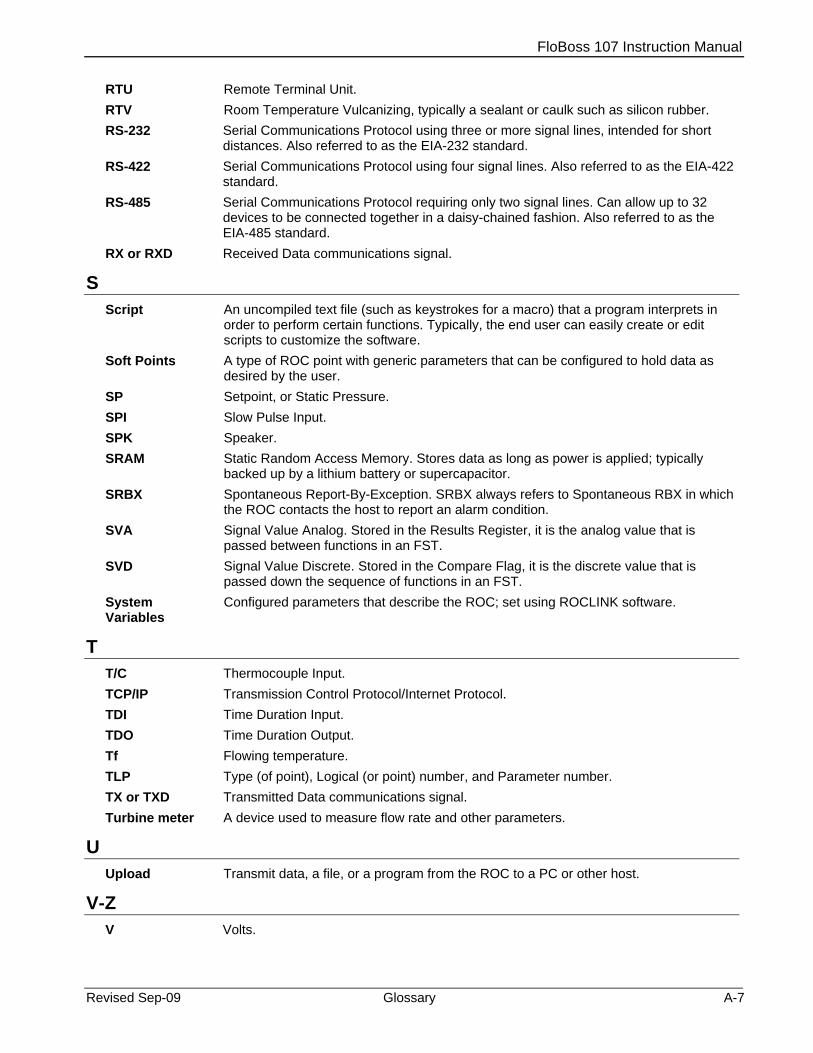
FloBoss 107 Instruction Manual
Revised Sep-09 Glossary A-7
RTU Remote Terminal Unit. RTV Room Temperature Vulcanizing, typically a sealant or caulk such as silicon rubber. RS-232 Serial Communications Protocol using three or more signal lines, intended for short
distances. Also referred to as the EIA-232 standard. RS-422 Serial Communications Protocol using four signal lines. Also referred to as the EIA-422
standard. RS-485 Serial Communications Protocol requiring only two signal lines. Can allow up to 32
devices to be connected together in a daisy-chained fashion. Also referred to as the EIA-485 standard.
RX or RXD Received Data communications signal.
S Script An uncompiled text file (such as keystrokes for a macro) that a program interprets in
order to perform certain functions. Typically, the end user can easily create or edit scripts to customize the software.
Soft Points A type of ROC point with generic parameters that can be configured to hold data as desired by the user.
SP Setpoint, or Static Pressure. SPI Slow Pulse Input. SPK Speaker. SRAM Static Random Access Memory. Stores data as long as power is applied; typically
backed up by a lithium battery or supercapacitor. SRBX Spontaneous Report-By-Exception. SRBX always refers to Spontaneous RBX in which
the ROC contacts the host to report an alarm condition. SVA Signal Value Analog. Stored in the Results Register, it is the analog value that is
passed between functions in an FST. SVD Signal Value Discrete. Stored in the Compare Flag, it is the discrete value that is
passed down the sequence of functions in an FST. System Variables
Configured parameters that describe the ROC; set using ROCLINK software.
T T/C Thermocouple Input. TCP/IP Transmission Control Protocol/Internet Protocol. TDI Time Duration Input. TDO Time Duration Output. Tf Flowing temperature. TLP Type (of point), Logical (or point) number, and Parameter number. TX or TXD Transmitted Data communications signal. Turbine meter A device used to measure flow rate and other parameters.
U Upload Transmit data, a file, or a program from the ROC to a PC or other host.
V-Z V Volts.

FloBoss 107 Instruction Manual
A-8 Glossary Revised Sep-09
[This page is intentionally left blank]

FloBoss 107 Instruction Manual
Revised Sep-09 Index I-1
Index
Numerals
250 Ohm Resistor Installed ................................ 4-9
A
Address MVS................................................................ 6-5
AGA .................................................................. 1-23 AI/DI
Troubleshooting............................................ 7-16 AI/DI (8-point)
Wiring ........................................................... 4-11 Alarm Log.......................................................... 1-15 Analog Inputs............................................. 4-9, 4-11
250 Ohm Resistor Installed ............................ 4-9 Troubleshooting.............................................. 7-9 Wiring ............................................................. 4-9
Analog Outputs ................................................. 4-13 Troubleshooting............................................ 7-10 Wiring ........................................................... 4-13
Antennas............................................................. 2-2 AO/DO (6 point) ................................................ 4-23 API .................................................................... 1-22 APP 485............................................................ 4-20
Wiring ........................................................... 4-20 Attaching an Expansion Rack............................. 2-8
B
Backplane ........................................................... 1-6 Backup................................................................ 7-5 Base unit
Installing ......................................................... 2-7 Base Unit with Adapter Plate.............................. 2-7 Battery................................................................. 1-8
Memory Backup..................................... 1-8, 2-11 Removing and Installing ............................... 2-12
C
Cathodic Protection ............................................ 2-6 Central Processing Unit
See CPU....................................................... 2-13 Clock
Real-Time..................................................... 1-21 CMOS Microprocessor ....................................... 1-6 COM1........................................................... 1-9, 5-3
Wiring ............................................................. 5-6 COM2........................................................... 1-9, 5-3
Wiring ............................................................. 5-6 COM3......................................................... 1-11, 5-3
Wiring ...................................................... 5-6, 5-7 Communication Modules
COM3 ........................................................... 1-11
Communications 485.................................................................. 5-3 Built-in............................................................. 1-8 COM1 ............................................................. 5-3 COM2 ............................................................. 5-3 COM3 ............................................................. 5-3 LOI .................................................................. 5-3 Modules .......................................................... 5-3 Overview......................................................... 5-1 Pass Through ............................................... 1-18 Troubleshooting.............................................. 7-4 Wiring.............................................................. 5-1 Wiring EIA-232 (RS-232)................................ 5-7 Wiring EIA-485 (RS-485)................................ 5-6 Wiring LOI....................................................... 5-5
Communications modules Technical specifications................................ 5-16
Compliance ......................................................... 2-4 Configuration................................................ 7-5, 7-8 CPU............................................................ 1-6, 2-13
I/O Assembly ......................................... 1-10, 4-1 Installing........................................................ 2-15 Removing...................................................... 2-14
D
Daily Historical Log ........................................... 1-15 Defaults
EIA-232........................................................... 5-7 EIA-485........................................................... 5-6 LCD................................................................. 5-8 LOI .................................................................. 5-5
Detaching an Expansion Rack.......................... 2-10 Diagnostic ........................................................... 1-8
Inputs ............................................................ 1-21 Dial-up Modem.................................................. 5-15 Differential Pressure ......................................... 1-23 Digital Inputs ..................................................... 4-11 Dimensions ......................................................... 2-2 Direct Connect .................................................... 5-6 Discrete Inputs
Troubleshooting............................................ 7-11 Wiring...................................................4-14, 4-15
Discrete Output Relay Wiring............................................................ 4-18
Discrete Outputs Troubleshooting............................................ 7-11 Wiring...................................................4-16, 4-18
Dry Relay Contacts ........................................... 4-14 DVS................................................................... 1-12
Troubleshooting............................................ 7-15
E
ECM
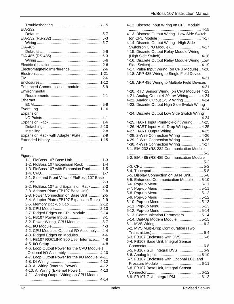
FloBoss 107 Instruction Manual
I-2 Index Revised Sep-09
Troubleshooting............................................ 7-15 EIA-232
Defaults .......................................................... 5-7 EIA-232 (RS-232) ............................................... 5-3
Wiring ............................................................. 5-7 EIA-485
Defaults .......................................................... 5-6 EIA-485 (RS-485) ............................................... 5-3
Wiring ............................................................. 5-6 Electrical Isolation.................................................2-6 Electromagnetic Interference.............................. 2-6 Electronics ........................................................ 1-21 EMI...................................................................... 2-6 Enclosures ........................................................ 1-12 Enhanced Communication module..................... 5-9 Environmental
Requirements ................................................. 2-1 Ethernet
ECM................................................................ 5-9 Event Log.......................................................... 1-16 Expansion
I/O Points........................................................ 4-1 Expansion Rack.................................................. 1-6
Detaching ..................................................... 2-10 Installing ......................................................... 2-8
Expansion Rack with Adapter Plate ................... 2-9 Extended History .............................................. 1-15
F
Figures 1-1. FloBoss 107 Base Unit ........................... 1-3 1-2. FloBoss 107 Expansion Rack ................. 1-4 1-3. FloBoss 107 with Expansion Rack.......... 1-5 1-4. CPU......................................................... 1-7 2-1. Side and Front View of FloBoss 107 Base
Unit ............................................................... 2-3 2-2. FloBoss 107 and Expansion Rack .......... 2-3 2-3. Adapter Plate (FB107 Base Unit)............ 2-8 2-3. Power Connection on Base Unit ............. 2-5 2-4. Adapter Plate (FB107 Expansion Rack) . 2-9 2-5. Memory Backup Cap............................. 2-12 2-6. CPU Module.......................................... 2-13 2-7. Ridged Edges on CPU Module ............. 2-14 3-1. FB107 Power Inputs................................ 3-1 3-2. Power Wiring, CPU Module .................... 3-7 4-1. I/O Module............................................... 4-3 4-2. CPU Module’s Optional I/O Assembly .... 4-4 4-3. Ridged Edges on Modules...................... 4-6 4-4. FB107 ROCLINK 800 User Interface...... 4-8 4-5. I/O Setup ................................................. 4-8 4-6. Loop Output Power for the CPU Module’s
Optional I/O Assembly ............................... 4-10 4-7. Loop Output Power for the I/O Module . 4-11 4-8. DI Wiring ............................................... 4-12 4-9. AI Wiring (Internal Power)..................... 4-12 4-10. AI Wiring (External Power).................. 4-13 4-11. Analog Output Wiring on CPU Module
................................................................... 4-14
4-12. Discrete Input Wiring on CPU Module .................................................................... 4-15
4-13. Discrete Output Wiring - Low Side Switch (on CPU Module )....................................... 4-17
4-14. Discrete Output Wiring - High Side Switch(on CPU Module)............................. 4-17
4-15. Discrete Output Relay Module Wiring (High Side Switch)...................................... 4-18
4-16. Discrete Output Relay Module Wiring (Low Side Switch) ............................................... 4-19
4-17. Pulse Input Wiring (on CPU Module) .. 4-20 4-18. APP 485 Wiring to Single Field Device
.................................................................... 4-21 4-19. APP 485 Wiring to Multiple Field Devices
.................................................................... 4-21 4-20. RTD Sensor Wiring (on CPU Module) 4-23 4-21. Analog Output 4-20 mA Wiring ........... 4-24 4-22. Analog Output 1-5 V Wiring ................ 4-24 4-23. Discrete Output High Side Switch Wiring
.................................................................... 4-24 4-24. Discrete Output Low Side Switch Wiring
.................................................................... 4-24 4-25. HART Input Point-to-Point Wiring ....... 4-25 4-26. HART Input Multi-Drop Wiring............. 4-25 4-27. HART Output Wiring ........................... 4-25 4-28. 2-Wire Connection Wiring ................... 4-26 4-29. 2-Wire Connection Wiring ................... 4-26 4-30. 4-Wire Connection Wiring ................... 4-27 5-1. EIA-232 (RS-232 Communication Module
...................................................................... 5-2 5-2. EIA-485 (RS-485 Communication Module
...................................................................... 5-2 5-3. CPU......................................................... 5-2 5-4. Touchpad ................................................ 5-8 5-5. Display Connection on Base Unit............ 5-8 5-5. Enhanced Communication Module ....... 5-10 5-6. Pop-up Menu......................................... 5-11 5-7. Pop-up Menu......................................... 5-11 5-8. Pop-up Menu......................................... 5-12 5-9. Pop-up Menu......................................... 5-12 5-10. Pop-up Menu....................................... 5-13 5-11. Pop-up Menu....................................... 5-13 5-12. Pop-up Menu....................................... 5-14 5-13. Communication Parameters................ 5-14 5-14. Dial-Up Modem Module ...................... 5-15 6-1. MVS Wiring ............................................. 6-2 6-2. MVS Multi-Drop Configuration (Two
Transmitters) ................................................ 6-4 6-3. FB107 Enclosure with DVS..................... 6-6 6-4. FB107 Base Unit, Integral Sensor
Connector..................................................... 6-8 6-5. FB107 GUI, Integral DVS........................ 6-9 6-6. Analog Input .......................................... 6-10 6-7. FB107 Enclosure with Optional LCD and
Pressure Module ........................................ 6-11 6-8. FB107 Base Unit, Integral Sensor
Connector................................................... 6-12 6-9. FB107 GUI, Integral PM........................ 6-13

FloBoss 107 Instruction Manual
Revised Sep-09 Index I-3
6-10. Analog Input ........................................ 6-14 7-1. FB107 GUI .............................................. 7-2 7-2. MVS Depressurization .......................... 7-14 7-3. DVS Depressurization........................... 7-16
Firmware........................................................... 1-13 FloBoss 107 Flow Manager ................................ 1-1 FloBoss 107 Flow Manager LCD User Manual 1-24 Flow Measurement ........................................... 1-22 Function Sequence Tables
FST............................................................... 1-17
G
Grid Impedance....................................................2-6 Ground Rod..........................................................2-6 Grounding
Earth Ground....................................................2-6 Installing ......................................................... 2-6 Wiring Requirements...................................... 2-5
GUI...................................................................... 7-2
H
Hardware ............................................................ 1-5 Hardware Watchdog ......................................... 1-22 HART
Wiring ........................................................... 4-25 HART module ................................................... 4-24 History Log........................................................ 1-15 History Points.................................................... 1-14 Hourly Historical Log......................................... 1-15 Humidity .............................................................. 2-2
I
I/O ....................................................................... 4-1 Analog Inputs......................................... 4-9, 4-11 Analog Outputs............................................. 4-13 APP 485 ....................................................... 4-20 Built-in............................................................. 1-8 CPU I/O Assembly ....................................... 1-10 Database ...................................................... 1-17 Digital Inputs................................................. 4-11 Discrete Inputs.............................................. 4-14 Discrete Output Relay .................................. 4-17 Discrete Outputs........................................... 4-15 I/O Setup tab .................................................. 4-8 Modules ........................................................ 1-10 MVS................................................................ 6-1 Optional ........................................................ 1-10 Pulse Inputs.................................................. 4-19 RTD .............................................................. 4-21 Selecting Types.............................................. 4-7 Terminations............................................ 4-2, 4-3 Troubleshooting.............................................. 7-4 Wiring ...................................................... 2-6, 4-6 Wiring Requirements...................................... 3-6
I/O modules Technical specifications ............................... 4-27
Impedance
Grid ................................................................. 2-6 Input/Output
I/O ................................................................... 4-1 Installing
Batteries........................................................ 2-12 CPU Module ................................................. 2-15 FB107 with an Expansion Rack ..................... 2-8 FB107 without an Expansion Rack ................ 2-7 Grounding....................................................... 2-6 Module Covers ............................................. 2-10 Modules .......................................................... 4-5 MVS Module ............................................ 6-3, 6-4 Power Wiring .................................................. 3-6 Requirements ................................................. 2-1 Wire Channel Covers ................................... 2-11
ISO.................................................................... 1-23 Isolation ............................................................... 2-6
L
LCD Defaults........................................................... 5-8 Wiring.............................................................. 5-8
LCD Touchpad.................................................. 1-12 LEDs .....................................................5-4, 5-5, 5-7
Troubleshooting.............................................. 7-3 License Key .............................................1-12, 2-15 Lightning Protection ............................................ 6-6 Local Operator Interface
LOI ........................................................... 1-8, 5-5 Local Port............................................................ 5-3 Locking mechanism ............................................ 4-6 Log data .............................................................. 7-5 Logical............................................................... 1-14 LOI ............................................................... 1-8, 5-3
Defaults........................................................... 5-5 Using............................................................... 5-6 Wiring.............................................................. 5-5
Loop Output Power .................................... 1-10, 4-9 Low Power Modes ............................................ 1-22
M
Memory ............................................................... 1-6 Memory Backup ................................1-8, 2-11, 2-12 Microprocessor ................................................... 1-6 Min / Max Historical Log.................................... 1-15 Minute Historical Log ........................................ 1-15 Modbus Protocol ........................................ 1-19, 5-4 Module Cover.................................................... 2-10 Module Placement
Communication............................................... 5-1 I/O ................................................................... 4-1
Modules 6-Point AO/DO.............................................. 4-23 ECM................................................................ 5-9 HART............................................................ 4-24 Installing.......................................................... 4-5 Locking mechanism........................................ 4-6

FloBoss 107 Instruction Manual
I-4 Index Revised Sep-09
Removing ....................................................... 4-6 RTD .............................................................. 4-26
Monitoring ......................................................... 1-21 Multi-Variable Sensor
MVS................................................................ 6-3 MVS ........................................................... 1-12, 6-1
Address .......................................................... 6-5 Installing .................................................. 6-3, 6-4 Set Back to Factory Defaults........................ 7-15 Troubleshooting..................................... 7-7, 7-14
N
National Electrical Code NEC......................................................... 2-4, 3-2
O
Opcodes ........................................................... 1-18 Operating Range
Temperature................................................... 2-2 Operation .......................................................... 2-16 Overview............................................................. 1-2
P
Parameters ....................................................... 1-14 Pass Through Communications ....................... 1-18 Periodic Log
See Hourly Historical Log............................. 1-15 PID Control ....................................................... 1-17 PM
Troubleshooting............................................ 7-16 Point.................................................................. 1-14
Type.............................................................. 1-14 Polarity.............................................................. 1-22 Power
Consumption .................................................. 3-3 Low Modes ................................................... 1-22 Requirements .......................................... 2-4, 3-2 Sleep Mode .................................................. 1-22 Surge Protection ..............................................2-5 Troubleshooting.............................................. 7-6 Wiring ...................................................... 3-1, 3-7
Preserving Configuration and Log Data ............. 7-5 Pressure module (PM)...................................... 1-12 Processor............................................................ 1-6 Product Overview ............................................... 1-2 Protocols
ROC and Modbus.................................. 1-19, 5-4 Pulse Inputs ............................................. 1-23, 4-19
Troubleshooting............................................ 7-12 Wiring ........................................................... 4-19
R
Radio Frequency Interference ............................ 2-6 RBX Function.................................................... 1-18 Real-Time Clock ............................................... 1-21 Removing
Batteries ....................................................... 2-12 CPU Module ................................................. 2-14 Expansion Rack............................................ 2-10 Module Covers ............................................. 2-10 Modules .......................................................... 4-6 Power ............................................................. 7-8 Wire Channel Covers ................................... 2-11
Reset................................................................... 7-8 RST ................................................................ 1-6
Reset Switch..................................................... 2-15 Resistance Temperature Detector
See RTD Inputs ............................................ 4-21 Resistance Temperature Detector module....... 4-26 Restart ................................................................ 7-8 RFI ...................................................................... 2-6 ROC Protocol............................................. 1-19, 5-4 ROCLINK 800
Troubleshooting.............................................. 7-6 ROCLINK 800 Configuration Software ............. 1-19 ROCLINK 800 Configuration Software User Manual
........................................................................ 1-23 RTD..........................................1-8, 1-10, 1-23, 4-21
Troubleshooting.............................................. 7-7 Wiring ........................................................... 4-22
RTD Inputs.......................................................... 4-1 Troubleshooting................................... 7-12, 7-17
RTD module...................................................... 4-26 RTOS................................................................ 1-13 RX ................................................................ 5-4, 5-5
S
Security ............................................................. 1-16 COM1 ...................................................... 1-9, 5-6 COM2 ...................................................... 1-9, 5-7 COM3 ............................................................. 5-6 LOI........................................................... 1-9, 5-5
Selecting I/O Types ........................................................ 4-7
Set Back to Factory Defaults MVS.............................................................. 7-15
Site Requirements .............................................. 2-2 Sleep Mode....................................................... 1-22 Softpoints .......................................................... 1-18 Specifications
Communications modules ............................ 5-16 I/O modules .................................................. 4-27
SRBX ................................................................ 1-18 Standard History ............................................... 1-14 Start .................................................................... 7-8 Startup and Operation ...................................... 2-16 Static Pressure.................................................. 1-23 Static Random Access Memory
SRAM ............................................................. 1-6 Super-cap .................................................. 1-8, 2-11 Surge Protection...................................................2-5
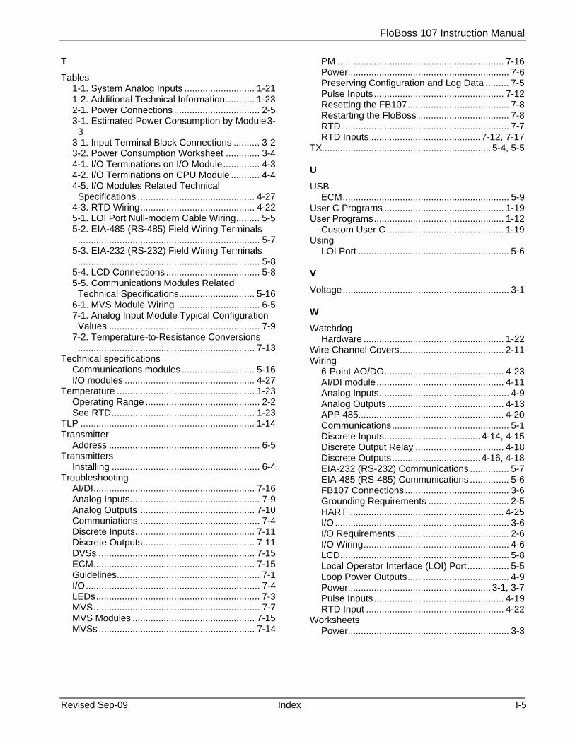
FloBoss 107 Instruction Manual
Revised Sep-09 Index I-5
T
Tables 1-1. System Analog Inputs ........................... 1-21 1-2. Additional Technical Information........... 1-23 2-1. Power Connections ................................. 2-5 3-1. Estimated Power Consumption by Module3-
3 3-1. Input Terminal Block Connections .......... 3-2 3-2. Power Consumption Worksheet ............. 3-4 4-1. I/O Terminations on I/O Module.............. 4-3 4-2. I/O Terminations on CPU Module ........... 4-4 4-5. I/O Modules Related Technical
Specifications ............................................. 4-27 4-3. RTD Wiring............................................ 4-22 5-1. LOI Port Null-modem Cable Wiring......... 5-5 5-2. EIA-485 (RS-485) Field Wiring Terminals
...................................................................... 5-7 5-3. EIA-232 (RS-232) Field Wiring Terminals
...................................................................... 5-8 5-4. LCD Connections .................................... 5-8 5-5. Communications Modules Related
Technical Specifications............................. 5-16 6-1. MVS Module Wiring ................................ 6-5 7-1. Analog Input Module Typical Configuration
Values .......................................................... 7-9 7-2. Temperature-to-Resistance Conversions
.................................................................... 7-13 Technical specifications
Communications modules ............................ 5-16 I/O modules .................................................. 4-27
Temperature ..................................................... 1-23 Operating Range ............................................ 2-2 See RTD....................................................... 1-23
TLP ................................................................... 1-14 Transmitter
Address .......................................................... 6-5 Transmitters
Installing ......................................................... 6-4 Troubleshooting
AI/DI.............................................................. 7-16 Analog Inputs.................................................. 7-9 Analog Outputs............................................. 7-10 Communiations............................................... 7-4 Discrete Inputs.............................................. 7-11 Discrete Outputs........................................... 7-11 DVSs ............................................................ 7-15 ECM.............................................................. 7-15 Guidelines....................................................... 7-1 I/O................................................................... 7-4 LEDs............................................................... 7-3 MVS................................................................ 7-7 MVS Modules ............................................... 7-15 MVSs ............................................................ 7-14
PM ................................................................ 7-16 Power.............................................................. 7-6 Preserving Configuration and Log Data ......... 7-5 Pulse Inputs.................................................. 7-12 Resetting the FB107....................................... 7-8 Restarting the FloBoss ................................... 7-8 RTD ................................................................ 7-7 RTD Inputs ..........................................7-12, 7-17
TX................................................................. 5-4, 5-5
U
USB ECM................................................................ 5-9
User C Programs .............................................. 1-19 User Programs.................................................. 1-12
Custom User C ............................................. 1-19 Using
LOI Port .......................................................... 5-6
V
Voltage................................................................ 3-1
W
Watchdog Hardware ...................................................... 1-22
Wire Channel Covers........................................ 2-11 Wiring
6-Point AO/DO.............................................. 4-23 AI/DI module................................................. 4-11 Analog Inputs.................................................. 4-9 Analog Outputs............................................. 4-13 APP 485........................................................ 4-20 Communications............................................. 5-1 Discrete Inputs.....................................4-14, 4-15 Discrete Output Relay .................................. 4-18 Discrete Outputs..................................4-16, 4-18 EIA-232 (RS-232) Communications ............... 5-7 EIA-485 (RS-485) Communications ............... 5-6 FB107 Connections ........................................ 3-6 Grounding Requirements ............................... 2-5 HART............................................................ 4-25 I/O ................................................................... 3-6 I/O Requirements ........................................... 2-6 I/O Wiring........................................................ 4-6 LCD................................................................. 5-8 Local Operator Interface (LOI) Port................ 5-5 Loop Power Outputs....................................... 4-9 Power....................................................... 3-1, 3-7 Pulse Inputs.................................................. 4-19 RTD Input ..................................................... 4-22
Worksheets Power.............................................................. 3-3

FloBoss 107 Instruction Manual
If you have comments or questions regarding this manual, please direct them to your local sales representative or contact:
Emerson Process Management Remote Automation Solutions Marshalltown, IA 50158 U.S.A. Watertown, CT 06795 U.S.A. Houston, TX 77065 U.S.A. Pickering, North Yorkshire UK Y018 7JA Website: www.EmersonProcess.com/Remote
I-6 Index Revised Sep-09