Embed Size (px)
Citation preview

Brodogradnja/Shipbuilding Volume 65 Numbe 2, 2014
Većeslav Čorić Ivan Ćatipović Vedran Slapničar
ISSN 0007-215X eISSN 1845-5859
FLOATING CRANE RESPONSE IN SEA WAVES
UDC 629.5(045)
Original scientific paper
Summary
Many activities present in the offshore technology are affected by sea waves and their safety strongly depends on the sea state. The fundamental question in operation risk analysis is the limit sea state which enables the safe operation controlled in all phases: from the sea surface to the sea bottom. The safe limit sea state is especially important when some lifting operation is performed in sea waves. This paper presents a dynamical model of a floating crane in sea waves with a hanging load at a high altitude above sea level. The model is defined as a linearized coupled double pendulum where the usual 6 DOF of the floating crane oscillatory motions in waves are extended by additional 3 DOF of the swinging load. The numerical model of the floating crane is calibrated and tuned according to the measured model in a towing tank. The significant values of the crane boom top accelerations were estimated for the given design sea state with different vertical load positions. The problem is illustrated by the example of a floating crane consisting of a simple single pontoon with an ordinary land crane mounted on the deck. The reliability of the proposed method is evaluated on the basis of correlation between the calculated and measured data.
Key words: heavy lifting in sea waves, sea-keeping analysis, double pendulum,
operating limit sea state
1. Introduction
A heavy load suspended by a steel rope from a crane boom acts like a pendulum and an oscillatory swinging motion of the load is excited by horizontal and vertical acceleration of the crane boom top. Although the mathematical analysis of such a pendulum has been dated from the time of Newton, it has not been still completely and clearly understood in the offshore practice. It is complicated for several reasons:
- the boom acceleration which is due to the vessel’s oscillatory motion in waves is a stochastic process, sometimes even non-stationary,
- the length of the pendulum (elastic steel rope) is changing due to the load vertical oscillations,
- when the oscillating amplitudes are large, the pendulum model is nonlinear.
Floating Crane Response V. Čorić, I. Ćatipović, in Sea Waves V. Slapničar
112
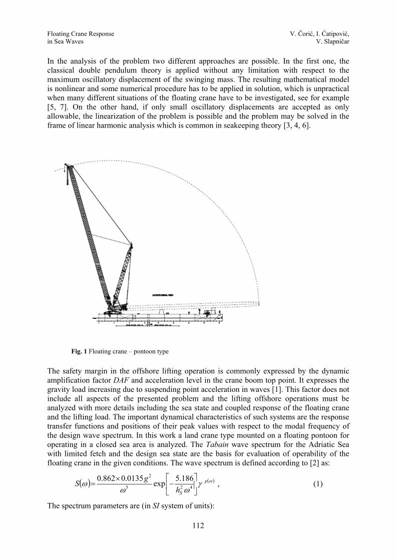
In the analysis of the problem two different approaches are possible. In the first one, the classical double pendulum theory is applied without any limitation with respect to the maximum oscillatory displacement of the swinging mass. The resulting mathematical model is nonlinear and some numerical procedure has to be applied in solution, which is unpractical when many different situations of the floating crane have to be investigated, see for example [5, 7]. On the other hand, if only small oscillatory displacements are accepted as only allowable, the linearization of the problem is possible and the problem may be solved in the frame of linear harmonic analysis which is common in seakeeping theory [3, 4, 6].
Fig. 1 Floating crane – pontoon type
The safety margin in the offshore lifting operation is commonly expressed by the dynamic amplification factor DAF and acceleration level in the crane boom top point. It expresses the gravity load increasing due to suspending point acceleration in waves [1]. This factor does not include all aspects of the presented problem and the lifting offshore operations must be analyzed with more details including the sea state and coupled response of the floating crane and the lifting load. The important dynamical characteristics of such systems are the response transfer functions and positions of their peak values with respect to the modal frequency of the design wave spectrum. In this work a land crane type mounted on a floating pontoon for operating in a closed sea area is analyzed. The Tabain wave spectrum for the Adriatic Sea with limited fetch and the design sea state are the basis for evaluation of operability of the floating crane in the given conditions. The wave spectrum is defined according to [2] as:
( ) ( )ωγωω
ω p
ShgS ⎥
⎦
⎤⎢⎣
⎡−
×= 425
2 186.5exp0135.0862.0 , (1)
The spectrum parameters are (in SI system of units):
Floating Crane Response V. Čorić, I. Ćatipović, in Sea Waves V. Slapničar
113
20135.0862.0 gA ×=
2Sh
186.5B =
63.1=γ
( )⎩⎨⎧
>≤
=⎥⎥⎦
⎤
⎢⎢⎣
⎡ −−=
m
m
m
m
zaza
pωωωω
σωσ
ωω10.008.0
;2
exp 22
2
The modal frequency of the spectrum is given by the following simple relation:
60.0h80.132.0
Sm +
+=ω
where hS is the significant wave height (in meters).
2. Coupled oscillatory motion The suspending (attachment) point of the lifting mass mL is usually on the crane boom
top which experiences oscillatory motions ( )tδ as a consequence of the pontoon motion ( )tlinη and ( )trotη in sea waves. The first vector designates translational and the second one
rotational oscillatory displacements. If the position of the suspending point P(xP,yP,zP) is given in the body coordinate system by radii vector kzjyixr PPPP ++= , the point combined motion will be defined in vector form as:
PPP
rotlin
zyx
kjikjikji
r
654321321 ηηηηηηδδδ
ηηδ
+++=++=
=×+=
, (2)
where ηj =ηj(t) are three translational j = 1, 2, 3 and three rotational j = 4, 5, 6 degrees of freedom (DOF) of the vessel’s oscillatory motion in waves, see Fig 2. The same is given in matrix notation as{ } [ ]{ }ηδ Ω= , which in the developed form reads:
(3) The acceleration vector of the crane boom top P is derived straight forward as the
second time derivative of equation (2). For the relatively small mass of the crane load compared with the crane vessel mass,
and for the suspending point which is not far from the system (pontoon and crane) centre of gravity G, the dynamic analysis may be simplified and the whole problem is analyzed as uncoupled. The motion of the suspended mass (load) may be mathematically modelled in such case as a pendulum with an oscillating support. When the pontoon is exposed to harmonic wave, the pendulation of the mass is considered as the forced harmonic motion and
( )( )( )
( )( )( )( )( )( )⎪⎪
⎪⎪
⎭
⎪⎪⎪⎪
⎬
⎫
⎪⎪⎪⎪
⎩
⎪⎪⎪⎪
⎨
⎧
⎥⎥⎥
⎦
⎤
⎢⎢⎢
⎣
⎡
−−
−=
⎪⎭
⎪⎬
⎫
⎪⎩
⎪⎨
⎧
tttttt
xyxzyz
ttt
PP
PP
PP
6
5
4
3
2
1
3
2
1
01000010
0001
ηηηηηη
δδδ
Floating Crane Response V. Čorić, I. Ćatipović, in Sea Waves V. Slapničar
114
the suspension point P(xP,yP,zP) oscillates according to the specific function of time obtained from the standard seakeeping analysis. This function is given by equation (2).
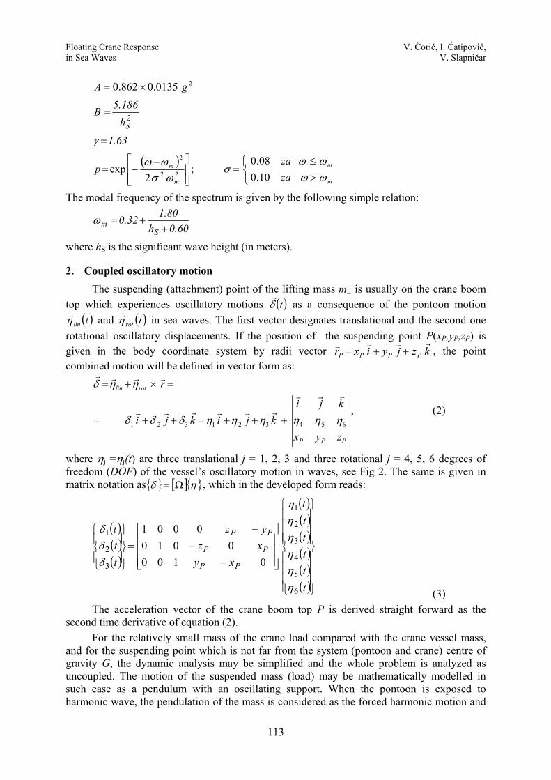
If the mass of the suspended load is large compared with the crane and the pontoon mass, or even if the mass is moderate but it is hanged at a high altitude above sea level, the problem must be considered as coupled. When the vessel oscillatory motions and pendulum rotations ( )tmLθ are large, the analysis of the problem becomes complex, especially if it is considered in stochastic sea waves. In that case the governing equations for the dynamic response of a floating crane coupled with the pendulum motion of the load are usually derived from Lagrange’s equations of dynamic equilibrium.
Fig. 2 Swinging of the suspended mass - linearized model
η 7 η 8
P’
P(x,y,z) δ 1
δ 1
δ3
δ 2
δ 2 δ 3
η 7 η 8
η 9 η 2 η3
η 1
Q(x,y,z-l)
Q’
Q” l, le
η 6 η 5
η 4
AE
O
δ1
g mL
α
x
z
x
y
z
δ 2
g mL
β
y
z
λ
le + δ le
η 9
O O
cw G
δ 3
δ 3
m
AE θ
mL
P P P
ltg 17 δηα −
=ll
δl 39 δη −=
ltg 28 δηβ −
=
Floating Crane Response V. Čorić, I. Ćatipović, in Sea Waves V. Slapničar
115
3. Linearization of the model In realistic conditions, only small oscillations are acceptable in lifting operations in waves
and it is obvious that the problem may be approximated by linear model on account of small displacements. The linear coupled analysis is based on the simple relations between the suspending point P oscillatory motion ( )tδ and the rotation pendulum angles ( )tmLθ . In that case the displacement vector η on the right side of equation (2) is extended by additional rotational displacements of the load mass mL in longitudinal and transversal vertical planes:
( ) ( )( ) ( )tlt
tltβηαη
sinsin
8
7
==
(4)
The displacement in vertical direction is: ( ) ( )( )tlt θη cos19 −= (5)
If it is assumed that displacements { } { } θβαηδ ,,,, (see Fig. 2) are the first order small values, may be idealized by straight displacements in tangential directions and the following simple equations are obtained:
( )651717 1 ηηηηδηα PP yz
lltg +−−=
−= (6)
( )462828 1 ηηηηδηβ PP zx
lltg +−−=
−= (7)
In the above equations 1δ and 2δ are displacements of the point P according to equation (3), l is the outstretched rope length and , , are the point P coordinates in the body coordinate system, see Fig. 2. In this system gravitational and restoring forces are dominant, much larger than inertial forces. To take their action in realistic way, the rope elastic stretching ε / and the rope effective stiffness AE must be taken into account. Again, for small displacements it is given as:
( )543939 1 ηηηη
δηδPP xy
llll
+−−=−
= (8)
These relations describe linear compatibility between the vessel DOF and additional load mass mL displacements. They allow simple definition of the dynamic equilibrium by Newton’s law in the Cartesian coordinate system. In opposite case the definition of the equilibrium should be done by the Lagrange equations of motion in polar coordinates with complex and nonlinear relations for inertial and damping forces [6, 7]. The linear model has also two additional advantages:
- the problem is convenient for linear harmonic seakeeping analysis based on sea waves spectrum,
- it allows visible parametric variation of the main parameters in operability analysis like variation of attachment point P position, length l and wave heading angle μ.
On the basis of accepted assumptions, the relation between the restoring forces and the displacement vector is established, see Fig. 2:
Floating Crane Response V. Čorić, I. Ćatipović, in Sea Waves V. Slapničar
116
(9) 0 0 0 0 0
0 0 0 0AE AE AE 0 0 0 AE
AE AE 0 AE
AE 0 AE
0
. 0 0
0AE
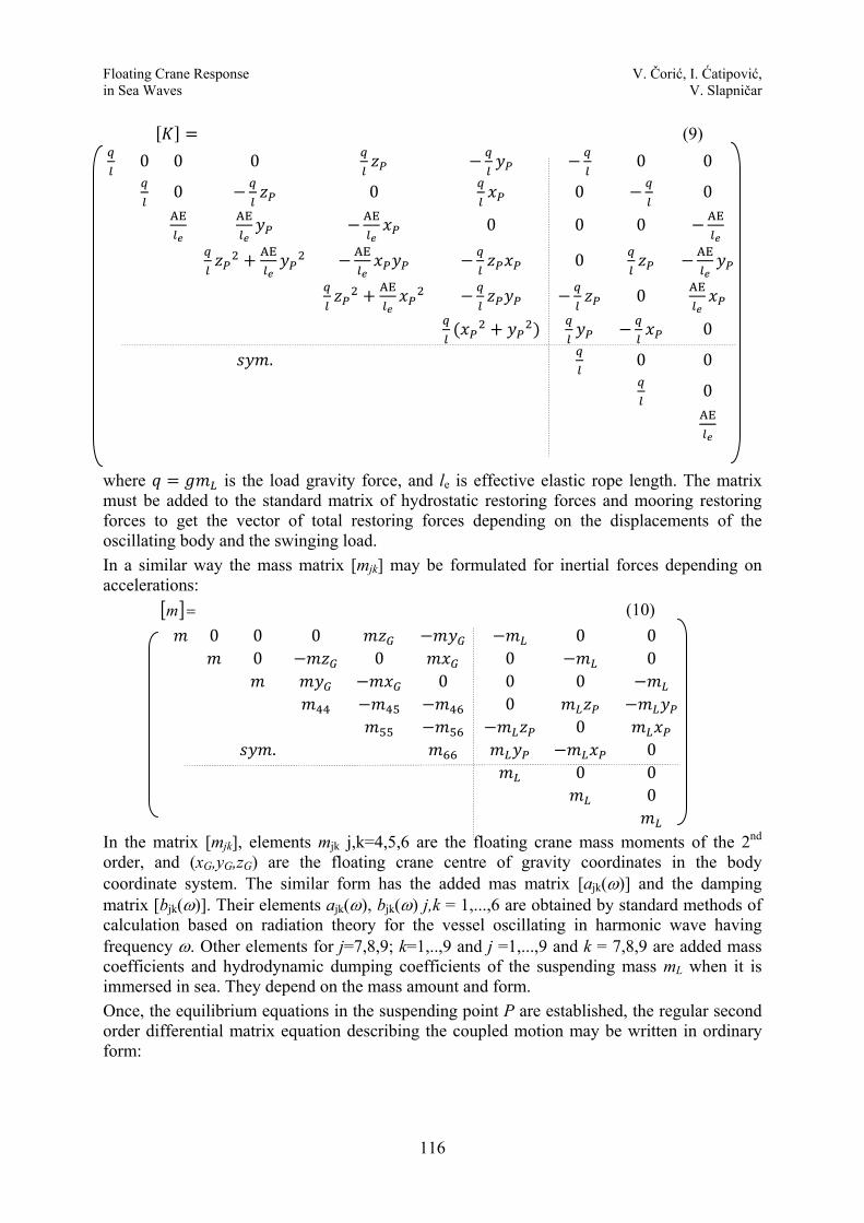
where is the load gravity force, and le is effective elastic rope length. The matrix must be added to the standard matrix of hydrostatic restoring forces and mooring restoring forces to get the vector of total restoring forces depending on the displacements of the oscillating body and the swinging load. In a similar way the mass matrix [mjk] may be formulated for inertial forces depending on accelerations: [ ] =m (10)
0 0 0 0 00 0 0 0
0 0 00
0. 0
0 00
In the matrix [mjk], elements mjk j,k=4,5,6 are the floating crane mass moments of the 2nd order, and (xG,yG,zG) are the floating crane centre of gravity coordinates in the body coordinate system. The similar form has the added mas matrix [ajk(ω)] and the damping matrix [bjk(ω)]. Their elements ajk(ω), bjk(ω) j,k = 1,...,6 are obtained by standard methods of calculation based on radiation theory for the vessel oscillating in harmonic wave having frequency ω. Other elements for j=7,8,9; k=1,..,9 and j =1,...,9 and k = 7,8,9 are added mass coefficients and hydrodynamic dumping coefficients of the suspending mass mL when it is immersed in sea. They depend on the mass amount and form. Once, the equilibrium equations in the suspending point P are established, the regular second order differential matrix equation describing the coupled motion may be written in ordinary form:
Floating Crane Response V. Čorić, I. Ćatipović, in Sea Waves V. Slapničar
117
[ ] ( )[ ]( ){ } ( )[ ]{ } [ ]{ } ( ){ }( ) ( ){ }{ }
9,...,1,
Re
=
=
==+++
kj
eF
tFkbamti
ja
jaijkjjkjjkjk
ωωωζ
ζηηωηω
(11)
where aζ is the wave amplitude at frequency ω. For the harmonic excitation system, (11) is transferred into the system of complex linear equations of harmonic response ti
ajj e ωηη = , j = 1,…,6; j = 7,…,9:
[ ] [ ][ ] [ ]
[ ] [ ][ ] [ ]
[ ] [ ][ ] [ ]
[ ] [ ][ ] [ ]
{ }{ }
{ }{ } ⎭
⎬⎫
⎩⎨⎧
=⎭⎬⎫
⎩⎨⎧
⎟⎟⎟⎟⎟
⎠
⎞
⎜⎜⎜⎜⎜
⎝
⎛
⎥⎦
⎤⎢⎣
⎡⎥⎦
⎤⎢⎣
⎡+
+⎟⎟⎠
⎞⎜⎜⎝
⎛⎥⎦
⎤⎢⎣
⎡+⎥
⎦
⎤⎢⎣
⎡−⎥
⎦
⎤⎢⎣
⎡
2
1
2
1
2221
1211
2221
1211
2221
12112
2221
1211
FF
BBBB
i
AAAA
mmmm
KKKK
aζηη
ω
ω
(12)
In the above equation the matrices [ ] [ ] [ ] [ ]11111111 ,,, BAmK are restoring, mass, added mass and hydrodynamic dumping matrix, respectively, well known in seakeeping theory. Vector { }1F is the excitation vector due to incoming and diffracted wave component acting on the vessel’s wetted surface and { }2F is the excitation vector acting on mass mL. When the load is above the sea free surface, all elements of coupling matrices which are due to hydrodynamic forces are equal zero.
The final solution of the complex system of equations gives the vector of transfer functions of the coupled vessel response in waves:
( ){ } ( ) ( ){ } 6,...,11== jiiH ja
aj ωη
ωζω (13)
and swinging mass response:
( ){ } ( ) ( ){ } 9,8,71== jiiH aj
aj ωη
ωζω (14)
The shape of the transfer functions depends strongly on the suspending point P coordinates , , and the rope length l which defines the pendulum natural frequency for the point mass mL:
(15)
When the mass mL has a large mass moment of inertia, the length l must be replaced by leffective, which results with the real polar mass moment of inertia to the point P.
4. Illustrative example Evaluation of the method was done by comparing the calculated and measured values of
the floating crane oscillatory motion in waves, without and with a swinging load. The floating crane presented in Fig. 1 has the following main particulars:
length L = 75.00 m breadth B = 31.00 m depth to the deck H = 4.50 m
Floating Crane Response V. Čorić, I. Ćatipović, in Sea Waves V. Slapničar
118
draughts, working D1 = 2.46 m, D2 = 2,66 m displacement Δ1 = 5964 t , Δ2 = 6458 t suspended mass mL = 3.405 % Δ1 point P coordinates , , 1.137 , 0.0 , 0.759 rope length l = 1.333 L.
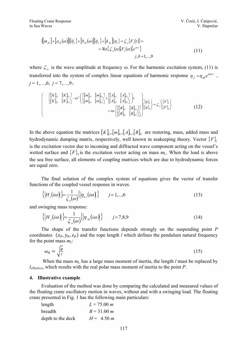
A common type of movable land crane is mounted and fixed on the pontoon deck. The crane capacity (load/height) is 48 t / 43 m to 248 t / 97.5 m. The standard radiation/diffraction package [8] was extended by the described method to investigate the operability of the floating crane in given sea condition. The design sea state is defined by the local sea wave spectrum for significant wave height hS = 1.3 m. The hydrodynamic model is shown in Fig. 4. The same model was scaled and investigated in waves in the towing tank, see Fig. 3.
4.1 Calibration of the numerical model The suspending point P is very high above sea level and the rolling and pitching modes of oscillations affect the mass swinging strongly. These DOFs are very important in coupled analysis of the floating crane and mass mL pendulation. On the other hand, the accuracy of their calculation depends on two sensitive parameters which must be precisely defined:
- total rolling damping B44(ω) consisting of potential, viscous and eddy-making damping,
- mass moment of inertia m44 about body x axis.
Fig. 3 - Physical model in the towing tank Fig. 4 - Numerical model (hydrodynamic
panel and mass model)
To match the numerical model to the physical one in the towing tank, these parameters were estimated from the free rolling test of the model without suspended load. In the case when the oscillatory motion is reduced to one DOF, i.e. the rolling only, the characteristic equation of free damped oscillations is:
Ω Ω 0 (16)
P , ,
Floating Crane Response V. Čorić, I. Ćatipović, in Sea Waves V. Slapničar
119
where Ω4 is the complex natural frequency of the free damped rolling oscillations: Ω λ (17)
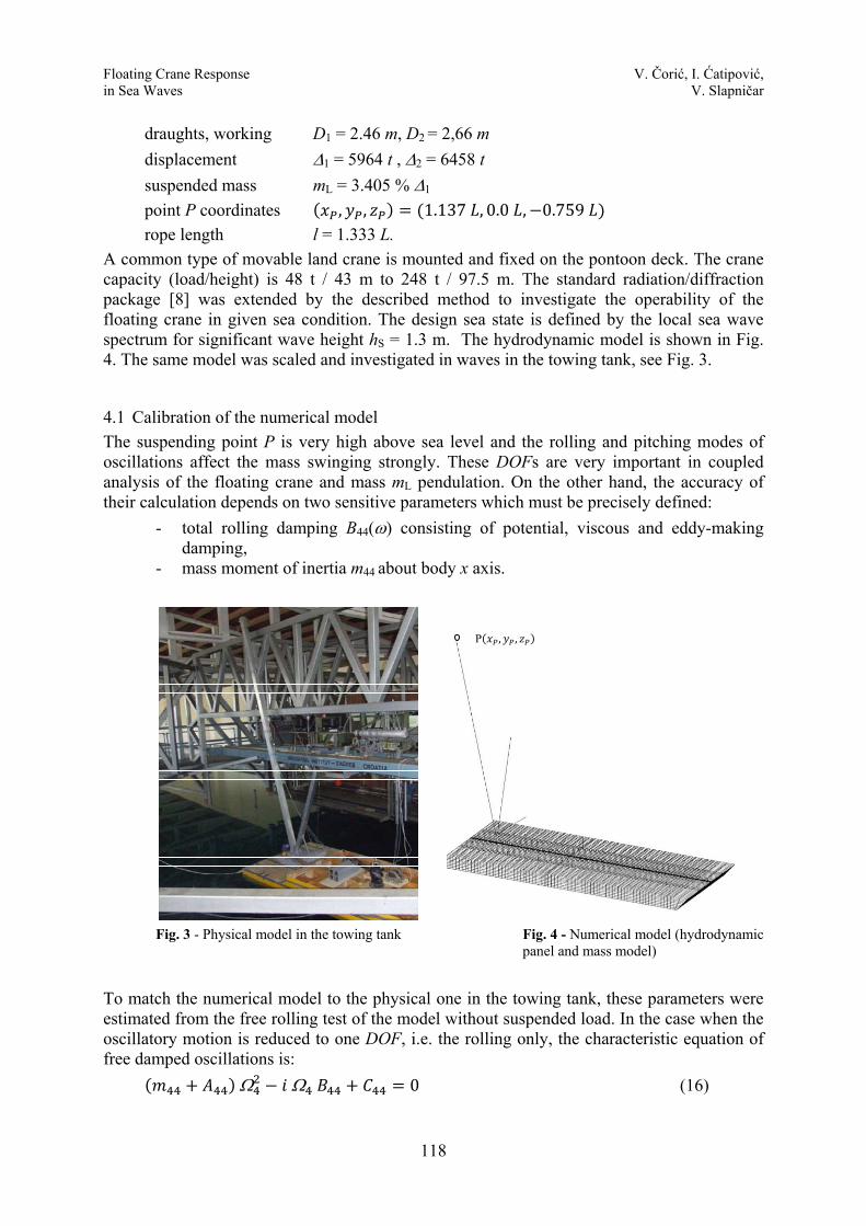
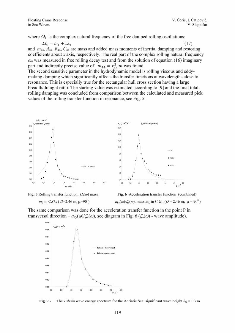
and m44, A44, B44, C44 are mass and added mass moments of inertia, damping and restoring coefficients about x axis, respectively. The real part of the complex rolling natural frequency ω4 was measured in free rolling decay test and from the solution of equation (16) imaginary part and indirectly precise value of was found. The second sensitive parameter in the hydrodynamic model is rolling viscous and eddy-making damping which significantly affects the transfer functions at wavelengths close to resonance. This is especially true for the rectangular hull cross section having a large breadth/draught ratio. The starting value was estimated according to [9] and the final total rolling damping was concluded from comparison between the calculated and measured pick values of the rolling transfer function in resonance, see Fig. 5.
Fig. 5 Rolling transfer function: Η4(ω) mass Fig. 6 Acceleration transfer function (combined)
mL in C.G.; ( D=2.46 m; μ=900) aPy(ω)/ζa(ω), mass mL in C.G.; (D = 2.46 m; μ = 900 )
The same comparison was done for the acceleration transfer function in the point P in transversal direction – aPy(ω)/ζa(ω), see diagram in Fig. 6 (ζa(ω) - wave amplitude).
Fig. 7 - The Tabain wave energy spectrum for the Adriatic Sea: significant wave height hS = 1.3 m
η4/ζa rad m‐1
(rxx=12.078 m; zG=1.45)
0,00
0,02
0,04
0,06
0,08
0,10
0,12
0,14
0,16
0,18
0,0 0,5 1,0 1,5 2,0 2,5 3,0 3,5
ω, rad/s
CALC. MEASU.
ay / ζa m2s‐1m‐1 (rxx=12.078 m ; zG=1.45 m )
0,0
2,0
4,0
6,0
8,0
10,0
12,0
14,0
16,0
0,0 0,5 1,0 1,5 2,0 2,5 3,0 3,5ω s ‐1
CALC.
MEASU.
MEASU.
0,00
0,02
0,04
0,06
0,08
0,10
0,12
0,14
0,16
0,18
0,0 0,5 1,0 1,5 2,0 2,5 3,0 3,5ω s ‐1
Sζζ(ω ) m2s
Tabain- theoretical.
Tabain - generated
Floating Crane Response V. Čorić, I. Ćatipović, in Sea Waves V. Slapničar
120
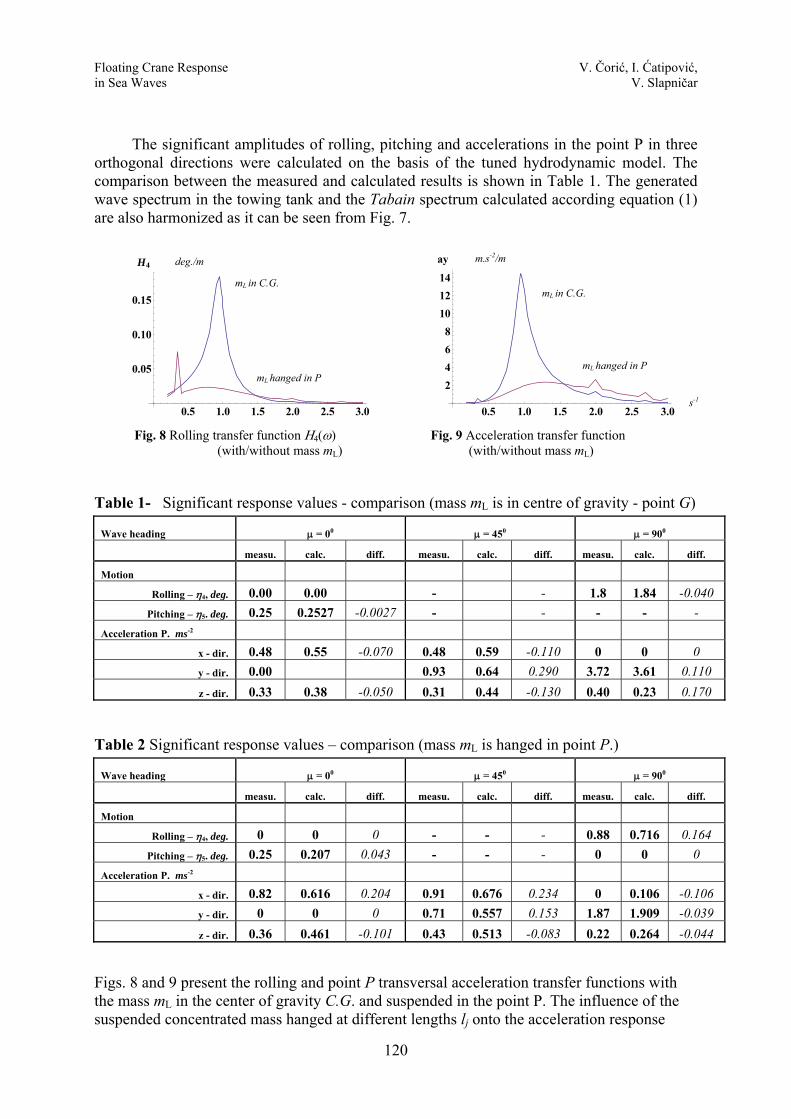
The significant amplitudes of rolling, pitching and accelerations in the point P in three
orthogonal directions were calculated on the basis of the tuned hydrodynamic model. The comparison between the measured and calculated results is shown in Table 1. The generated wave spectrum in the towing tank and the Tabain spectrum calculated according equation (1) are also harmonized as it can be seen from Fig. 7.
Fig. 8 Rolling transfer function Η4(ω) Fig. 9 Acceleration transfer function (with/without mass mL) (with/without mass mL)
Table 1- Significant response values - comparison (mass mL is in centre of gravity - point G)
Wave heading μ = 00 μ = 450 μ = 900
measu. calc. diff. measu. calc. diff. measu. calc. diff.
Motion Rolling – η4, deg. 0.00 0.00 - - 1.8 1.84 -0.040
Pitching – η5. deg. 0.25 0.2527 -0.0027 - - - - - Acceleration P. ms-2
x - dir. 0.48 0.55 -0.070 0.48 0.59 -0.110 0 0 0 y - dir. 0.00 0.93 0.64 0.290 3.72 3.61 0.110 z - dir. 0.33 0.38 -0.050 0.31 0.44 -0.130 0.40 0.23 0.170
Table 2 Significant response values – comparison (mass mL is hanged in point P.)
Wave heading μ = 00 μ = 450 μ = 900
measu. calc. diff. measu. calc. diff. measu. calc. diff.
Motion Rolling – η4, deg. 0 0 0 - - - 0.88 0.716 0.164
Pitching – η5. deg. 0.25 0.207 0.043 - - - 0 0 0 Acceleration P. ms-2
x - dir. 0.82 0.616 0.204 0.91 0.676 0.234 0 0.106 -0.106 y - dir. 0 0 0 0.71 0.557 0.153 1.87 1.909 -0.039 z - dir. 0.36 0.461 -0.101 0.43 0.513 -0.083 0.22 0.264 -0.044
Figs. 8 and 9 present the rolling and point P transversal acceleration transfer functions with the mass mL in the center of gravity C.G. and suspended in the point P. The influence of the suspended concentrated mass hanged at different lengths lj onto the acceleration response
0.5 1.0 1.5 2.0 2.5 3.0�
0.05
0.10
0.15
H4����
0.5 1.0 1.5 2.0 2.5 3.0�
2468
101214
ay����mL in C.G.
mL in C.G.
mL hanged in P mL hanged in P
deg./m m.s-2/m
s-1
Floating Crane Response V. Čorić, I. Ćatipović, in Sea Waves V. Slapničar
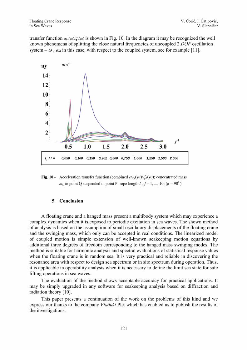
121
transfer function aPy(ω)/ζa(ω) is shown in Fig. 10. In the diagram it may be recognized the well known phenomena of splitting the close natural frequencies of uncoupled 2 DOF oscillation system – ω0, ω4 in this case, with respect to the coupled system, see for example [11].
Fig. 10 - Acceleration transfer function (combined aPy(ω)/ζa(ω); concentrated mass mL in point Q suspended in point P: rope length lj , j = 1, ..., 10; (μ = 900 )
5. Conclusion A floating crane and a hanged mass present a multibody system which may experience a
complex dynamics when it is exposed to periodic excitation in sea waves. The shown method of analysis is based on the assumption of small oscillatory displacements of the floating crane and the swinging mass, which only can be accepted in real conditions. The linearized model of coupled motion is simple extension of well-known seakeeping motion equations by additional three degrees of freedom corresponding to the hanged mass swinging modes. The method is suitable for harmonic analysis and spectral evaluations of statistical response values when the floating crane is in random sea. It is very practical and reliable in discovering the resonance area with respect to design sea spectrum or in site spectrum during operation. Thus, it is applicable in operability analysis when it is necessary to define the limit sea state for safe lifting operations in sea waves.
The evaluation of the method shows acceptable accuracy for practical applications. It may be simply upgraded in any software for seakeeping analysis based on diffraction and radiation theory [10].
This paper presents a continuation of the work on the problems of this kind and we express our thanks to the company Viadukt Plc. which has enabled us to publish the results of the investigations.
0.5 1.0 1.5 2.0 2.5 3.0�
2468
101214
ay����
l j / l = 0,050 0,100 0,150 0,262 0,500 0,750 1,000 1,250 1,500 2,000
m s-1
s-1
Floating Crane Response V. Čorić, I. Ćatipović, in Sea Waves V. Slapničar
122
REFERENCES
[1] Chakrabartati, S.K. et al.: Handbook of Offshore Engineering; Elsevier; Amsterdam
2005. [2] Tabain, T.: Standard Wind Wave Spectrum for Adriatic Sea Revisited (1977 – 1997);
Brodogradnja, 45 (1997). [3] Čorić, V.; Ćatipović, I.; Slapničar, V., Veić, D.: Heavy Lifting in Sea Waves –
Dynamic Citeria; Proceedings of the 5th Conference on Marine Technology – In memoriam of the Academician Zlatko Winkler; Rijeka, 2013.
[4] Ćatipović, I.; Čorić, V.; Veić, D.: Calculation of Floating Crane Natural Frequencies Based on Linearized Multybody Dynamics; Proceedings of the 30th International Conference on Ocean, Offshore and Arctic Engineering; OMAE 2011-49303; Rotterdam, The Netherlands, 2011.
[5] Klaus, F.G.; Vannahme, M.: An Experimental Study of the Nonlinear Dynamics of Floating Cranes; Proceedings of the 9th Offshore Polar Engineering Conference ISOPE-99; Brest, 1999.
[6] Malenica, Š.; Marc Orozco, J., Xiao-Bo Chen: Some Aspects of Seakeeping of the Floating Body with Attached Pendulum; Bureau Veritas, Paris.
[7] Ellermann, K.; Kreuzer, E.; Markiewicz, M.: Nonlinear Primary Resonances of a Floating Crane; Meccanica 38: 5–18, 2003.
[8] WADAM - Wave Analysis by Diffraction and Morison Theory, SESAM User Manual, DNV Software Report No.: 94-7100 / Revision5, Høvik, 2005.
[9] Tanaka, N.: A Study on the Bilge Keel, Part 4, On the Eddy-Making Resistance to the Rolling of a Ship Hull; Japan Soc. of Naval Arch., Vol. 109, 1960.
[10] Čorić, V.; Slapničar, V.: Seakeeping Characteristics of the Pontoon Crane for Operating Conditions in Malostonski Channel (in Croatian); Rep. 06307-900101-3 / Rev. 01; Faculty of Mechanical Engineering and Naval Architecture, University of Zagreb, 2009.
[11] Senjanović, I.; Ćatipović, I.; Tomašević, S.: Coupled Horizontal and Torsional Vibrations of a Flexible Barge; Engineering Structures 2007.
Submitted: 12.12.2013. Accepted: 24.05.2014.
Većeslav Čorić, Ivan Ćatipović, Vedran Slapničar Faculty of Mechanical Engineering and Naval Architecture, Unv. of Zagreb