Embed Size (px)
Citation preview
FlexPod Datacenter with VMware vSphere
6.0 and Fibre Channel Design Guide
FlexPod Datacenter with Fibre Channel SAN, VMware
vSphere 6.0 and NetApp ONTAP 9
Last Updated: November 11, 2016
2
About Cisco Validated Designs
The Cisco Validated Designs (CVD) program consists of systems and solutions designed, tested, and
documented to facilitate faster, more reliable, and more predictable customer deployments. For more
information, visit:
http://www.cisco.com/go/designzone.
ALL DESIGNS, SPECIFICATIONS, STATEMENTS, INFORMATION, AND RECOMMENDATIONS
(COLLECTIVELY, "DESIGNS") IN THIS MANUAL ARE PRESENTED "AS IS," WITH ALL FAULTS. CISCO AND
ITS SUPPLIERS DISCLAIM ALL WARRANTIES, INCLUDING, WITHOUT LIMITATION, THE WARRANTY OF
MERCHANTABILITY, FITNESS FOR A PARTICULAR PURPOSE AND NONINFRINGEMENT OR ARISING FROM
A COURSE OF DEALING, USAGE, OR TRADE PRACTICE. IN NO EVENT SHALL CISCO OR ITS SUPPLIERS BE
LIABLE FOR ANY INDIRECT, SPECIAL, CONSEQUENTIAL, OR INCIDENTAL DAMAGES, INCLUDING,
WITHOUT LIMITATION, LOST PROFITS OR LOSS OR DAMAGE TO DATA ARISING OUT OF THE USE OR
INABILITY TO USE THE DESIGNS, EVEN IF CISCO OR ITS SUPPLIERS HAVE BEEN ADVISED OF THE
POSSIBILITY OF SUCH DAMAGES.
THE DESIGNS ARE SUBJECT TO CHANGE WITHOUT NOTICE. USERS ARE SOLELY RESPONSIBLE FOR
THEIR APPLICATION OF THE DESIGNS. THE DESIGNS DO NOT CONSTITUTE THE TECHNICAL OR OTHER
PROFESSIONAL ADVICE OF CISCO, ITS SUPPLIERS OR PARTNERS. USERS SHOULD CONSULT THEIR
OWN TECHNICAL ADVISORS BEFORE IMPLEMENTING THE DESIGNS. RESULTS MAY VARY DEPENDING ON
FACTORS NOT TESTED BY CISCO.
CCDE, CCENT, Cisco Eos, Cisco Lumin, Cisco Nexus, Cisco StadiumVision, Cisco TelePresence, Cisco
WebEx, the Cisco logo, DCE, and Welcome to the Human Network are trademarks; Changing the Way We
Work, Live, Play, and Learn and Cisco Store are service marks; and Access Registrar, Aironet, AsyncOS,
Bringing the Meeting To You, Catalyst, CCDA, CCDP, CCIE, CCIP, CCNA, CCNP, CCSP, CCVP, Cisco, the
Cisco Certified Internetwork Expert logo, Cisco IOS, Cisco Press, Cisco Systems, Cisco Systems Capital, the
Cisco Systems logo, Cisco Unity, Collaboration Without Limitation, EtherFast, EtherSwitch, Event Center, Fast
Step, Follow Me Browsing, FormShare, GigaDrive, HomeLink, Internet Quotient, IOS, iPhone, iQuick Study,
IronPort, the IronPort logo, LightStream, Linksys, MediaTone, MeetingPlace, MeetingPlace Chime Sound,
MGX, Networkers, Networking Academy, Network Registrar, PCNow, PIX, PowerPanels, ProConnect,
ScriptShare, SenderBase, SMARTnet, Spectrum Expert, StackWise, The Fastest Way to Increase Your
Internet Quotient, TransPath, WebEx, and the WebEx logo are registered trademarks of Cisco Systems, Inc.
and/or its affiliates in the United States and certain other countries.
All other trademarks mentioned in this document or website are the property of their respective owners. The
use of the word partner does not imply a partnership relationship between Cisco and any other company.
(0809R)
© 2016 Cisco Systems, Inc. All rights reserved.
3
Table of Contents
About Cisco Validated Designs ................................................................................................................................................ 2
Executive Summary ................................................................................................................................................................. 5
Solution Overview .................................................................................................................................................................... 6
Introduction ......................................................................................................................................................................... 6
Audience ............................................................................................................................................................................. 6
Changes in FlexPod ............................................................................................................................................................. 6
FlexPod Program Benefits .................................................................................................................................................... 6
Technology Overview .............................................................................................................................................................. 8
FlexPod System Overview ................................................................................................................................................... 8
FlexPod Design Principles .................................................................................................................................................... 9
FlexPod Datacenter with Fibre channel SAN, VMware vSphere 6.0, and NetApp ONTAP 9 .................................................. 9
Validated System Hardware Components .......................................................................................................................... 15
Cisco Unified Computing System ................................................................................................................................... 15
Cisco UCS 6332 and 6332-16UP Fabric Interconnects ................................................................................................. 16
Cisco UCS 6248UP Fabric Interconnects ....................................................................................................................... 17
Cisco UCS 5108 Blade Server Chassis .......................................................................................................................... 18
Cisco UCS Fabric Extenders .......................................................................................................................................... 18
Cisco UCS B200 M4 Blade Servers ............................................................................................................................... 19
Cisco UCS C220 M4 Rack Servers ................................................................................................................................ 19
Cisco VIC 1340.............................................................................................................................................................. 20
Cisco VIC 1227.............................................................................................................................................................. 20
Cisco VIC 1387.............................................................................................................................................................. 20
Cisco UCS Differentiators .............................................................................................................................................. 21
Cisco UCS Features Specified in this Design ................................................................................................................. 22
Cisco Nexus 9000 Series Switch ................................................................................................................................... 23
Cisco MDS 9000 Series Multilayer SAN Switches .......................................................................................................... 24
VMware vSphere ........................................................................................................................................................... 24
NetApp FAS and ONTAP 9 ................................................................................................................................................ 25
NetApp All Flash FAS .................................................................................................................................................... 26
NetApp ONTAP 9 .......................................................................................................................................................... 27
IPspaces in ONTAP 9 ..................................................................................................................................................... 30
Domain and Element Management ..................................................................................................................................... 30
Cisco Unified Computing System Manager .................................................................................................................... 31
4
Cisco UCS Performance Manager ...................................................................................................................................... 31
Cisco Virtual Switch Update Manager (VSUM) (Optional) ................................................................................................... 32
VMware vCenter Server ................................................................................................................................................. 32
NetApp OnCommand System and Unified Manager ....................................................................................................... 32
NetApp OnCommand Performance Manager ................................................................................................................. 33
NetApp Virtual Storage Console .................................................................................................................................... 33
NetApp SnapManager and SnapDrive ............................................................................................................................ 33
Solution Architecture ............................................................................................................................................................. 35
Logical Build ...................................................................................................................................................................... 37
FlexPod Datacenter Delivering NFS to UCS B-Series Logical Build ................................................................................ 37
FlexPod Datacenter Delivering FC to Cisco UCS C-Series Logical Build ........................................................................ 40
Cisco Unified Computing System Design ....................................................................................................................... 42
Cisco Nexus 9000 Design .............................................................................................................................................. 46
NetApp AFF Storage Design .......................................................................................................................................... 48
ONTAP Configuration for vSphere ................................................................................................................................. 51
Management Design ...................................................................................................................................................... 53
Validation ............................................................................................................................................................................... 54
Validated Hardware and Software ...................................................................................................................................... 54
Summary ............................................................................................................................................................................... 56
References ............................................................................................................................................................................ 57
Products and Solutions ...................................................................................................................................................... 57
Interoperability Matrixes ..................................................................................................................................................... 58
About the Authors .................................................................................................................................................................. 59
Acknowledgements ........................................................................................................................................................... 59
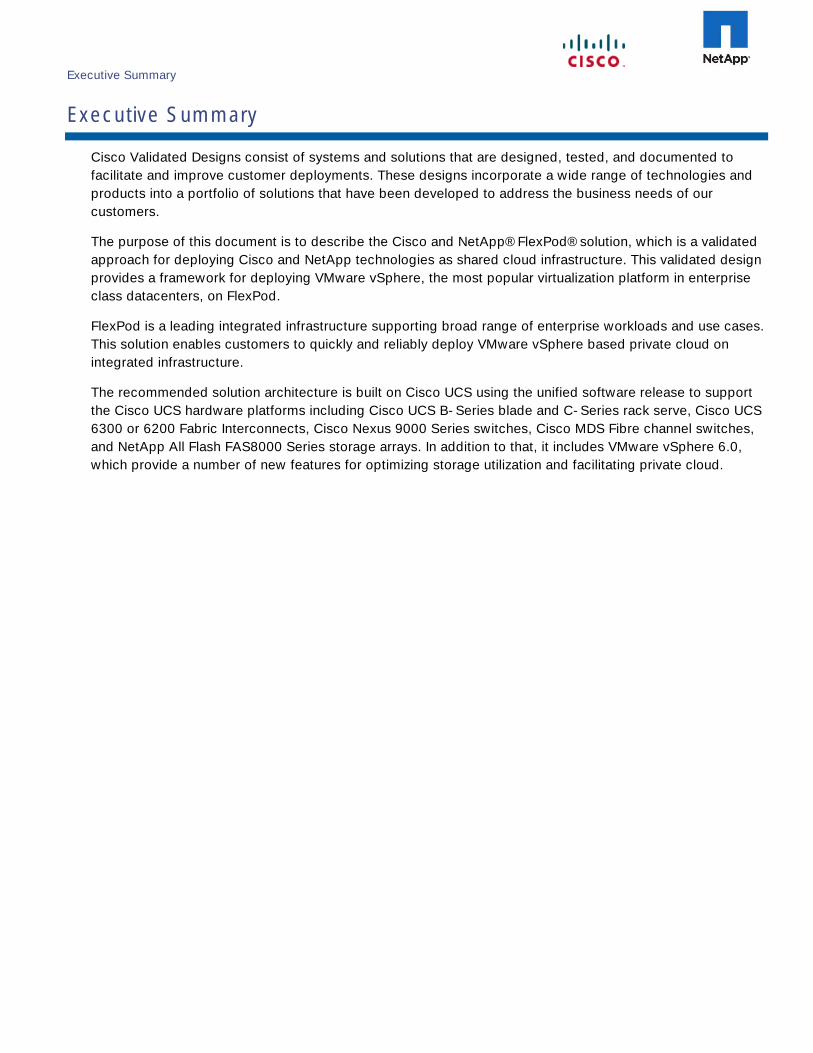
Executive Summary
Executive Summary
Cisco Validated Designs consist of systems and solutions that are designed, tested, and documented to
facilitate and improve customer deployments. These designs incorporate a wide range of technologies and
products into a portfolio of solutions that have been developed to address the business needs of our
customers.
The purpose of this document is to describe the Cisco and NetApp® FlexPod® solution, which is a validated
approach for deploying Cisco and NetApp technologies as shared cloud infrastructure. This validated design
provides a framework for deploying VMware vSphere, the most popular virtualization platform in enterprise
class datacenters, on FlexPod.
FlexPod is a leading integrated infrastructure supporting broad range of enterprise workloads and use cases.
This solution enables customers to quickly and reliably deploy VMware vSphere based private cloud on
integrated infrastructure.
The recommended solution architecture is built on Cisco UCS using the unified software release to support
the Cisco UCS hardware platforms including Cisco UCS B-Series blade and C-Series rack serve, Cisco UCS
6300 or 6200 Fabric Interconnects, Cisco Nexus 9000 Series switches, Cisco MDS Fibre channel switches,
and NetApp All Flash FAS8000 Series storage arrays. In addition to that, it includes VMware vSphere 6.0,
which provide a number of new features for optimizing storage utilization and facilitating private cloud.
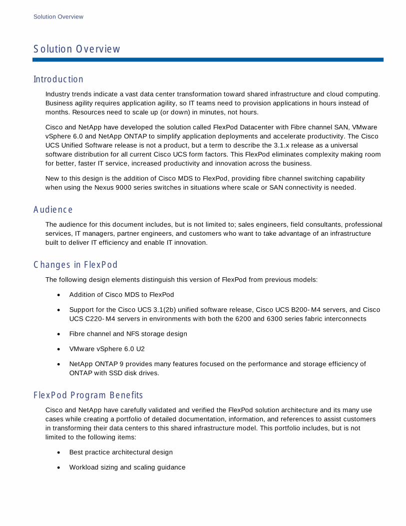
Solution Overview
Solution Overview
Introduction
Industry trends indicate a vast data center transformation toward shared infrastructure and cloud computing.
Business agility requires application agility, so IT teams need to provision applications in hours instead of
months. Resources need to scale up (or down) in minutes, not hours.
Cisco and NetApp have developed the solution called FlexPod Datacenter with Fibre channel SAN, VMware
vSphere 6.0 and NetApp ONTAP to simplify application deployments and accelerate productivity. The Cisco
UCS Unified Software release is not a product, but a term to describe the 3.1.x release as a universal
software distribution for all current Cisco UCS form factors. This FlexPod eliminates complexity making room
for better, faster IT service, increased productivity and innovation across the business.
New to this design is the addition of Cisco MDS to FlexPod, providing fibre channel switching capability
when using the Nexus 9000 series switches in situations where scale or SAN connectivity is needed.
Audience
The audience for this document includes, but is not limited to; sales engineers, field consultants, professional
services, IT managers, partner engineers, and customers who want to take advantage of an infrastructure
built to deliver IT efficiency and enable IT innovation.
Changes in FlexPod
The following design elements distinguish this version of FlexPod from previous models:
Addition of Cisco MDS to FlexPod
Support for the Cisco UCS 3.1(2b) unified software release, Cisco UCS B200-M4 servers, and Cisco
UCS C220-M4 servers in environments with both the 6200 and 6300 series fabric interconnects
Fibre channel and NFS storage design
VMware vSphere 6.0 U2
NetApp ONTAP 9 provides many features focused on the performance and storage efficiency of
ONTAP with SSD disk drives.
FlexPod Program Benefits
Cisco and NetApp have carefully validated and verified the FlexPod solution architecture and its many use
cases while creating a portfolio of detailed documentation, information, and references to assist customers
in transforming their data centers to this shared infrastructure model. This portfolio includes, but is not
limited to the following items:
Best practice architectural design
Workload sizing and scaling guidance
Solution Overview
7
Implementation and deployment instructions
Technical specifications (rules for what is a FlexPod configuration)
Frequently asked questions and answers (FAQs)
Cisco Validated Designs (CVDs) and NetApp Validated Architectures (NVAs) covering a variety of use
cases
Cisco and NetApp have also built a robust and experienced support team focused on FlexPod solutions,
from customer account and technical sales representatives to professional services and technical support
engineers. The support alliance between NetApp and Cisco gives customers and channel services partners
direct access to technical experts who collaborate with cross vendors and have access to shared lab
resources to resolve potential issues.
FlexPod supports tight integration with virtualized and cloud infrastructures, making it the logical choice for
long-term investment. FlexPod also provides a uniform approach to IT architecture, offering a well-
characterized and documented shared pool of resources for application workloads. FlexPod delivers
operational efficiency and consistency with the versatility to meet a variety of SLAs and IT initiatives,
including:
Application rollouts or application migrations
Business continuity and disaster recovery
Desktop virtualization
Cloud delivery models (public, private, hybrid) and service models (IaaS, PaaS, SaaS)
Asset consolidation and virtualization
Technology Overview
8
Technology Overview
FlexPod System Overview
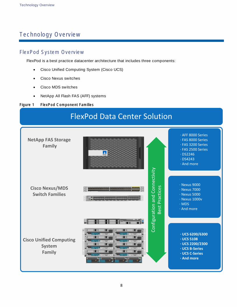
FlexPod is a best practice datacenter architecture that includes three components:
Cisco Unified Computing System (Cisco UCS)
Cisco Nexus switches
Cisco MDS switches
NetApp All Flash FAS (AFF) systems
Figure 1 FlexPod Component Families
SLOT
1
SLOT
5
SLOT
3
SLOT
7
SLOT
2
SLOT
6
SLOT
4
SLOT
8
!
UCS 5108
OK FAIL OK FAIL OK FAIL OK FAIL
! ResetConsole
! !
UCS B200 M1
! ResetConsole
! !
UCS B200 M1
! ResetConsole
! !
UCS B200 M1
! ResetConsole
! !
UCS B200 M1
! ResetConsole
! !
UCS B200 M1
! ResetConsole
! !
UCS B200 M1
! ResetConsole
! !
UCS B200 M1
! ResetConsole
! !
UCS B200 M1
NetApp FAS Storage Family
Cisco Nexus/MDS Switch Families
Cisco Unified Computing SystemFamily
∙ AFF 8000 Series∙ FAS 8000 Series∙ FAS 3200 Series∙ FAS 2500 Series∙ DS2246∙ DS4243∙ And more
∙ Nexus 9000∙ Nexus 7000∙ Nexus 5000∙ Nexus 1000v∙ MDS ∙ And more
∙ UCS 6200/6300∙ UCS 5108∙ UCS 2200/2300∙ UCS B-Series∙ UCS C-Series∙ And more
FlexPod Data Center Solution
Co
nfi
gura
tio
n a
nd
Co
nn
ecti
vity
Bes
t P
ract
ices
A B
FAS8060FAS8060
4
1
5
2
6
3
7 8 UCSC220 M4
Intel
Inside
XEON
Console!
CISCO NEXUS N9K-C9372PX
53 5451 5249 501 2 3 4 5 6 7 8 9 10 11 12 13 14 15 16 17 18 19 20 21 22 23 24 25 26 27 28 29 30 31 32 33 34 35 36 37 38 39 40 41 42 43 44 45 46 47 48
DS-C9148S-K9
P/S
FAN
STATUS
CO
NS
OL
EM
GM
T E
TH
LINK ACT
MDS 9148S 16G Multilayer Fabric Switch
47 4845 4643 4441 4239 4037 3835 3633 3431 3229 3027 2825 2623 2421 2219 2017 1815 1613 1411 129 107 85 63 41 2
USB
Technology Overview
9
These components are connected and configured according to best practices of both Cisco and NetApp to
provide the ideal platform for running a variety of enterprise workloads with confidence. FlexPod can scale
up for greater performance and capacity (adding compute, network, or storage resources individually as
needed), or it can scale out for environments that require multiple consistent deployments (rolling out
additional FlexPod stacks). The reference architecture covered in this document leverages the Cisco Nexus
9000 for the switching element.
One of the key benefits of FlexPod is the ability to maintain consistency at scale. Each of the component
families shown (Cisco UCS, Cisco Nexus, and NetApp AFF) offers platform and resource options to scale the
infrastructure up or down, while supporting the same features and functionality that are required under the
configuration and connectivity best practices of FlexPod.
FlexPod Design Principles
FlexPod addresses four primary design principles: availability, scalability, flexibility, and manageability. These
architecture goals are as follows:
Availability. Makes sure that services are accessible and ready to use for the applications.
Scalability. Addresses increasing demands with appropriate resources.
Flexibility. Provides new services or recovers resources without requiring infrastructure modification.
Manageability. Facilitates efficient infrastructure operations through open standards and APIs.
Note: Performance is a key design criterion that is not directly addressed in this document. It has been
addressed in other collateral, benchmarking, and solution testing efforts; this design guide validates the
functionality.
FlexPod Datacenter with Fibre channel SAN, VMware vSphere 6.0, and NetApp
ONTAP 9
FlexPod Datacenter with Fibre channel SAN, VMware vSphere 6.0, and NetApp ONTAP 9 is designed to be
fully redundant in the compute, network, and storage layers. There is no single point of failure from a device
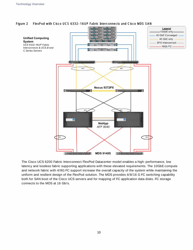
or traffic path perspective. Figure 2 illustrates the FlexPod topology using the Cisco MDS 9148S and Cisco
UCS 6300 Fabric Interconnect top-of-rack model while Figure 3 shows the same network and storage
elements paired with the Cisco UCS 6200 series Fabric Interconnects.
The Cisco UCS 6300 Fabric Interconnect FlexPod Datacenter model enables a high-performance, low
latency and lossless fabric supporting applications with these elevated requirements. The 40GbE compute
and network fabric with 4/8/16G FC support increase the overall capacity of the system while maintaining
the uniform and resilient design of the FlexPod solution. The MDS provides 4/8/16 G FC switching capability
both for SAN boot of the Cisco UCS servers and for mapping of FC application data disks. FC storage
connects to the MDS at 16 Gb/s.
Technology Overview
10
Figure 2 FlexPod with Cisco UCS 6332-16UP Fabric Interconnects and Cisco MDS SAN
The Cisco UCS 6200 Fabric Interconnect FlexPod Datacenter model enables a high-performance, low
latency and lossless fabric supporting applications with these elevated requirements. The 10GbE compute
and network fabric with 4/8G FC support increase the overall capacity of the system while maintaining the
uniform and resilient design of the FlexPod solution. The MDS provides 4/8/16 G FC switching capability
both for SAN boot of the Cisco UCS servers and for mapping of FC application data disks. FC storage
connects to the MDS at 16 Gb/s.
Technology Overview
11
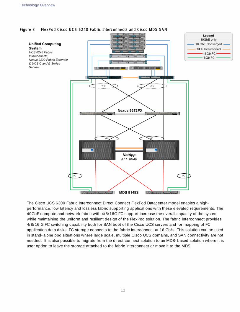
Figure 3 FlexPod Cisco UCS 6248 Fabric Interconnects and Cisco MDS SAN
The Cisco UCS 6300 Fabric Interconnect Direct Connect FlexPod Datacenter model enables a high-
performance, low latency and lossless fabric supporting applications with these elevated requirements. The
40GbE compute and network fabric with 4/8/16G FC support increase the overall capacity of the system
while maintaining the uniform and resilient design of the FlexPod solution. The fabric interconnect provides
4/8/16 G FC switching capability both for SAN boot of the Cisco UCS servers and for mapping of FC
application data disks. FC storage connects to the fabric interconnect at 16 Gb/s. This solution can be used
in stand-alone pod situations where large scale, multiple Cisco UCS domains, and SAN connectivity are not
needed. It is also possible to migrate from the direct connect solution to an MDS-based solution where it is
user option to leave the storage attached to the fabric interconnect or move it to the MDS.
Technology Overview
12
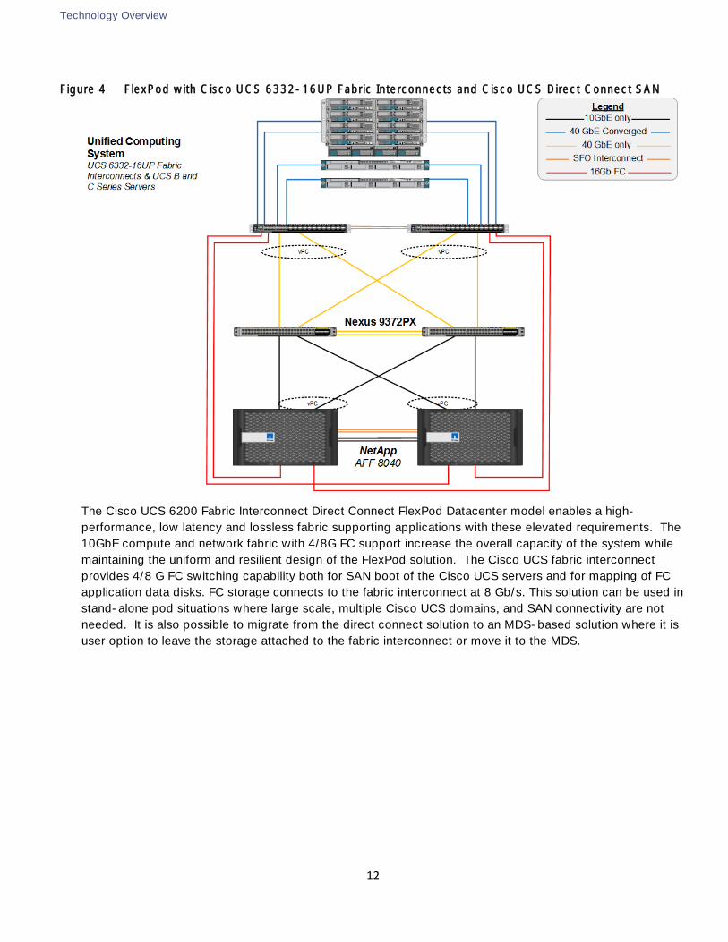
Figure 4 FlexPod with Cisco UCS 6332-16UP Fabric Interconnects and Cisco UCS Direct Connect SAN
The Cisco UCS 6200 Fabric Interconnect Direct Connect FlexPod Datacenter model enables a high-
performance, low latency and lossless fabric supporting applications with these elevated requirements. The
10GbE compute and network fabric with 4/8G FC support increase the overall capacity of the system while
maintaining the uniform and resilient design of the FlexPod solution. The Cisco UCS fabric interconnect
provides 4/8 G FC switching capability both for SAN boot of the Cisco UCS servers and for mapping of FC
application data disks. FC storage connects to the fabric interconnect at 8 Gb/s. This solution can be used in
stand-alone pod situations where large scale, multiple Cisco UCS domains, and SAN connectivity are not
needed. It is also possible to migrate from the direct connect solution to an MDS-based solution where it is
user option to leave the storage attached to the fabric interconnect or move it to the MDS.
Technology Overview
13
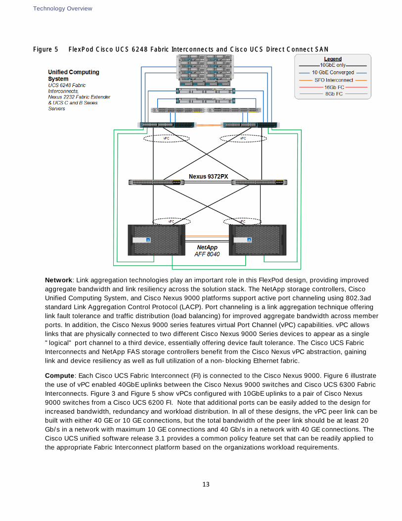
Figure 5 FlexPod Cisco UCS 6248 Fabric Interconnects and Cisco UCS Direct Connect SAN
Network: Link aggregation technologies play an important role in this FlexPod design, providing improved
aggregate bandwidth and link resiliency across the solution stack. The NetApp storage controllers, Cisco
Unified Computing System, and Cisco Nexus 9000 platforms support active port channeling using 802.3ad
standard Link Aggregation Control Protocol (LACP). Port channeling is a link aggregation technique offering
link fault tolerance and traffic distribution (load balancing) for improved aggregate bandwidth across member
ports. In addition, the Cisco Nexus 9000 series features virtual Port Channel (vPC) capabilities. vPC allows
links that are physically connected to two different Cisco Nexus 9000 Series devices to appear as a single
"logical" port channel to a third device, essentially offering device fault tolerance. The Cisco UCS Fabric
Interconnects and NetApp FAS storage controllers benefit from the Cisco Nexus vPC abstraction, gaining
link and device resiliency as well as full utilization of a non-blocking Ethernet fabric.
Compute: Each Cisco UCS Fabric Interconnect (FI) is connected to the Cisco Nexus 9000. Figure 6 illustrate
the use of vPC enabled 40GbE uplinks between the Cisco Nexus 9000 switches and Cisco UCS 6300 Fabric
Interconnects. Figure 3 and Figure 5 show vPCs configured with 10GbE uplinks to a pair of Cisco Nexus
9000 switches from a Cisco UCS 6200 FI. Note that additional ports can be easily added to the design for
increased bandwidth, redundancy and workload distribution. In all of these designs, the vPC peer link can be
built with either 40 GE or 10 GE connections, but the total bandwidth of the peer link should be at least 20
Gb/s in a network with maximum 10 GE connections and 40 Gb/s in a network with 40 GE connections. The
Cisco UCS unified software release 3.1 provides a common policy feature set that can be readily applied to
the appropriate Fabric Interconnect platform based on the organizations workload requirements.
Technology Overview
14
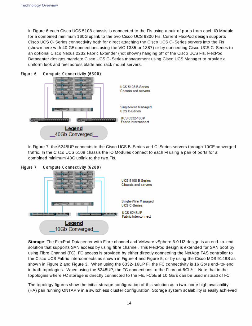
In Figure 6 each Cisco UCS 5108 chassis is connected to the FIs using a pair of ports from each IO Module
for a combined minimum 160G uplink to the two Cisco UCS 6300 FIs. Current FlexPod design supports
Cisco UCS C-Series connectivity both for direct attaching the Cisco UCS C-Series servers into the FIs
(shown here with 40 GE connections using the VIC 1385 or 1387) or by connecting Cisco UCS C-Series to
an optional Cisco Nexus 2232 Fabric Extender (not shown) hanging off of the Cisco UCS FIs. FlexPod
Datacenter designs mandate Cisco UCS C-Series management using Cisco UCS Manager to provide a
uniform look and feel across blade and rack mount servers.
Figure 6 Compute Connectivity (6300)
In Figure 7, the 6248UP connects to the Cisco UCS B-Series and C-Series servers through 10GE converged
traffic. In the Cisco UCS 5108 chassis the IO Modules connect to each FI using a pair of ports for a
combined minimum 40G uplink to the two FIs.
Figure 7 Compute Connectivity (6200)
Storage: The FlexPod Datacenter with Fibre channel and VMware vSphere 6.0 U2 design is an end-to-end
solution that supports SAN access by using fibre channel. This FlexPod design is extended for SAN boot by
using Fibre Channel (FC). FC access is provided by either directly connecting the NetApp FAS controller to
the Cisco UCS Fabric Interconnects as shown in Figure 4 and Figure 5, or by using the Cisco MDS 9148S as
shown in Figure 2 and Figure 3. When using the 6332-16UP FI, the FC connectivity is 16 Gb/s end-to-end
in both topologies. When using the 6248UP, the FC connections to the FI are at 8Gb/s. Note that in the
topologies where FC storage is directly connected to the FIs, FCoE at 10 Gb/s can be used instead of FC.
The topology figures show the initial storage configuration of this solution as a two-node high availability
(HA) pair running ONTAP 9 in a switchless cluster configuration. Storage system scalability is easily achieved
Technology Overview
15
by adding storage capacity (disks and shelves) to an existing HA pair, or by adding more HA pairs to the
cluster or storage domain.
Note: For SAN environments which are normally used in FlexPod, NetApp ONTAP allows up to 4 HA pairs
or 8 nodes. For NAS environments, it allows 12 HA pairs or 24 nodes to form a logical entity.
The HA interconnect allows each node in an HA pair to assume control of its partner's storage (disks and
shelves) directly. The local physical HA storage failover capability does not extend beyond the HA pair.
Furthermore, a cluster of nodes does not have to include similar hardware. Rather, individual nodes in an HA
pair are configured alike, allowing customers to scale as needed, as they bring additional HA pairs into the
larger cluster.
For more information about the virtual design of the environment that consists of VMware vSphere, VMware
vSphere Distributed Switch (vDS) or optional Cisco Nexus 1000v virtual distributed switching, and NetApp
storage controllers, refer to the Solution Design section below.
Validated System Hardware Components
The following components were used to validate the FlexPod Datacenter with Fibre channel and VMware
vSphere 6.0 U2 design:
Cisco Unified Computing System
Cisco Nexus 9000 Standalone Switch
Cisco MDS Multilayer Fabric Switch
NetApp All-Flash FAS Unified Storage
Cisco Unified Computing System
The Cisco Unified Computing System is a next-generation solution for blade and rack server computing. The
system integrates a low-latency; lossless 40 Gigabit Ethernet unified network fabric with enterprise-class,
x86-architecture servers. The system is an integrated, scalable, multi-chassis platform in which all resources
participate in a unified management domain. The Cisco Unified Computing System accelerates the delivery
of new services simply, reliably, and securely through end-to-end provisioning and migration support for
both virtualized and non-virtualized systems. The Cisco Unified Computing System consists of the following
components:
Compute - The system is based on an entirely new class of computing system that incorporates rack
mount and blade servers based on Intel Xeon E5 2600 v4 Series Processors.
Network - The system is integrated onto a low-latency, lossless, 40 or 10-Gbps unified network fabric.
This network foundation consolidates LANs, SANs, and high-performance computing networks which
are separate networks today. Cisco security, policy enforcement, and diagnostic features are now
extended into virtualized environments to better support changing business and IT requirements.
Storage access - The system provides consolidated access to both SAN storage and Network Attached
Storage (NAS) over the unified fabric. By unifying the storage access the Cisco Unified Computing
System can access storage over Ethernet (NFS, SMB 3.0 or iSCSI), Fibre Channel, and Fibre Channel
Technology Overview
16
over Ethernet (FCoE). This provides customers with storage choices and investment protection. In
addition, the server administrators can pre-assign storage-access policies to storage resources, for
simplified storage connectivity and management leading to increased productivity.
Management - the system uniquely integrates all system components to enable the entire solution to be
managed as a single entity by the Cisco UCS Manager. The Cisco UCS Manager has an intuitive
graphical user interface (GUI), a command-line interface (CLI), and a powerful scripting library module
for Microsoft PowerShell built on a robust application programming interface (API) to manage all system
configuration and operations.
Cisco Unified Computing System fuses access layer networking and servers. This high-performance,
next-generation server system provides a datacenter with a high degree of workload agility and
scalability.
Cisco UCS 6332 and 6332-16UP Fabric Interconnects
The Cisco UCS Fabric interconnects provide a single point for connectivity and management for the entire
system. Typically deployed as an active-
components into a single, highly-available management domain controlled by Cisco UCS Manager. The
fabric interconnects manage all I/O efficiently and securely at a single point, resulting in deterministic I/O
latency regardless of a server or virtual machi
The Fabric Interconnect provides both network connectivity and management capabilities for the Cisco UCS
system. IOM modules in the blade chassis support power supply, along with fan and blade management.
They also support port channeling and, thus, better use of bandwidth. The IOMs support virtualization-aware
networking in conjunction with the Fabric Interconnects and Cisco Virtual Interface Cards (VIC).
FI 6300 Series and IOM 2304 provide a few key advantages over the existing products. FI 6300 Series and
IOM 2304 support 40GbE / FCoE port connectivity that enables an end-to-end 40GbE / FCoE solution.
Unified ports support 4/8/16G FC ports for higher density connectivity to SAN ports.
Fabric Interconnect 6300 Series are 40G Fabric Interconnect products that double the switching capacity of
6200 Series data center fabric to improve workload density. Two 6300 Fabric Interconnect models have
been introduced supporting Ethernet, FCoE, and FC ports.
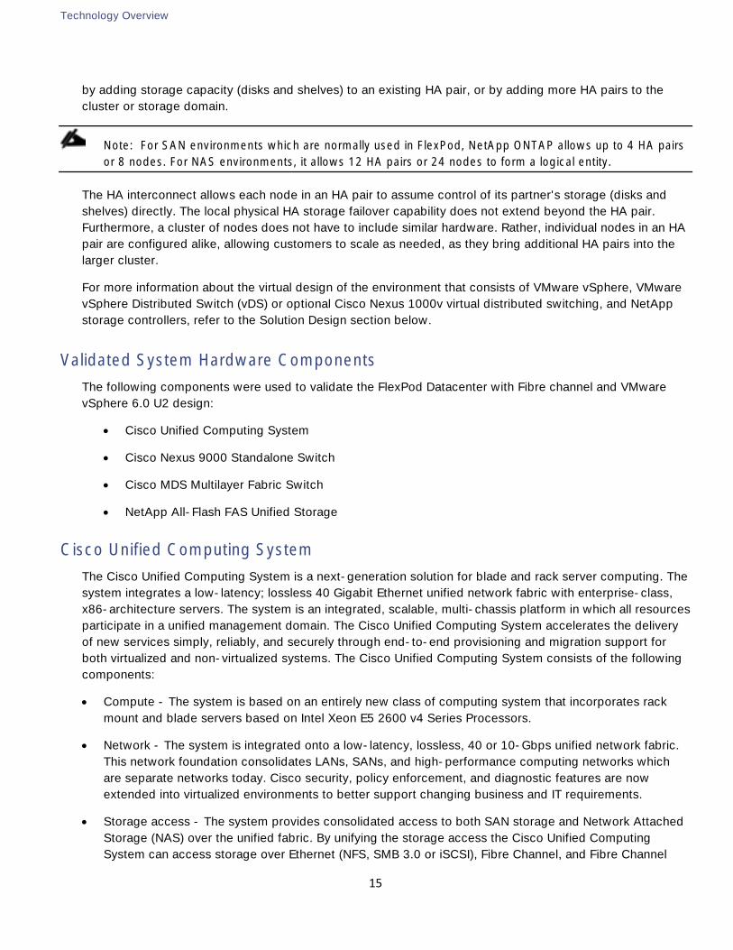
FI 6332 is a one-rack-unit (1RU) 40 Gigabit Ethernet, and FCoE switch offering up to 2.56 Tbps throughput
and up to 32 ports. The switch has 32 40Gbps fixed Ethernet, and FCoE ports. This Fabric Interconnect is
targeted for IP storage deployments requiring high performance 40G FCoE.
Technology Overview
17
Figure 8 Cisco 6332 Interconnect Front and Rear
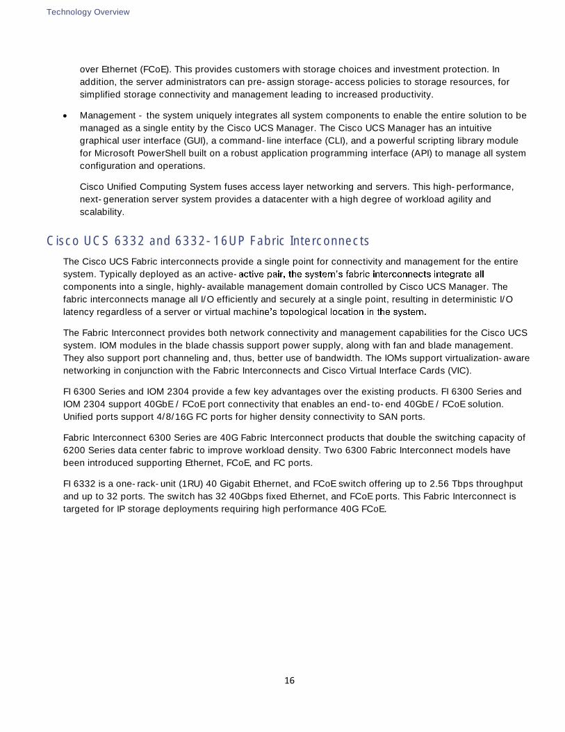
FI 6332-16UP is a one-rack-unit (1RU) 40 Gigabit Ethernet/FCoE switch and 1/10 Gigabit Ethernet,
FCoE and Fibre Channel switch offering up to 2.24 Tbps throughput and up to 40 ports. The switch has
24 40Gbps fixed Ethernet/FCoE ports and 16 1/10Gbps Ethernet/FCoE or 4/8/16G Fibre Channel ports.
This Fabric Interconnect is targeted for FC storage deployments requiring high performance 16G FC
connectivity.
Figure 9 Cisco 6332-16UP Fabric Interconnect Front and Rear
For more information, see: http://www.cisco.com/c/en/us/products/servers-unified-computing/ucs-6300-
series-fabric-interconnects/index.html
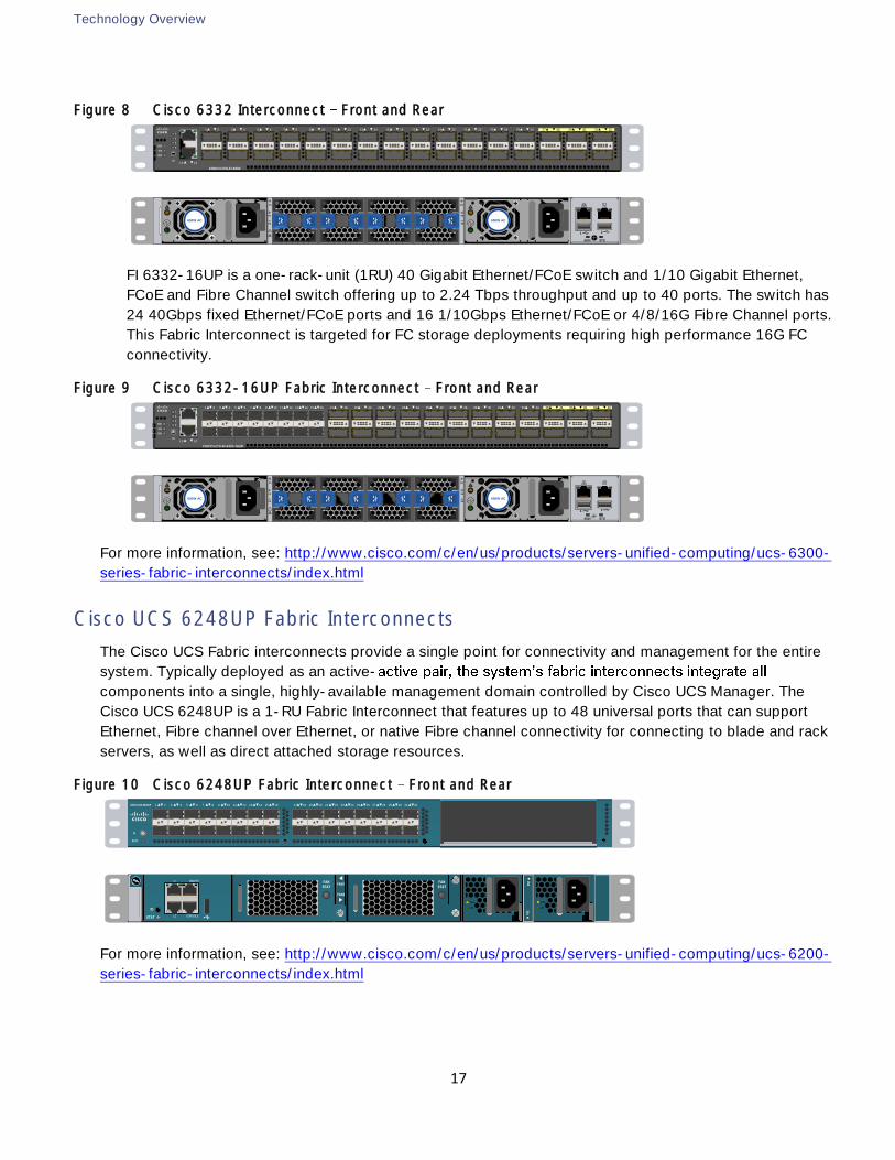
Cisco UCS 6248UP Fabric Interconnects
The Cisco UCS Fabric interconnects provide a single point for connectivity and management for the entire
system. Typically deployed as an active-
components into a single, highly-available management domain controlled by Cisco UCS Manager. The
Cisco UCS 6248UP is a 1-RU Fabric Interconnect that features up to 48 universal ports that can support
Ethernet, Fibre channel over Ethernet, or native Fibre channel connectivity for connecting to blade and rack
servers, as well as direct attached storage resources.
Figure 10 Cisco 6248UP Fabric Interconnect Front and Rear
For more information, see: http://www.cisco.com/c/en/us/products/servers-unified-computing/ucs-6200-
series-fabric-interconnects/index.html
CISCO UCS-FI-6332
ENV
LS
STS
BCN
1
2
3
4
L1 L2
1 2 3 4 5 6 7 8 9 10 11 12 13 14 15 16 17 18 19 20 21 22 23 24 25 26 31 3229 3027 28
P1
F1
!
F2
P2
F4
F3
BCN STS
1 2
650W AC 650W AC
CISCO UCS-FI-6332-16UP
ENV
LS
STS
BCN
1
2
3
4
L1 L2
17 18 19 20 21 22 23 24 25 26 27 28 29 30 31 32 33 34 39 4037 3835 361 2 3 4 5 6 7 8 9 10 11 12 13 14 15 16
P1
F1
!
F2
P2
F4
F3
BCN STS
1 2
650W AC 650W AC
CISCO UCS 6248UP 1 2 3 4 5 6 7 8 9 10 11 12 13 14 15 16 17 18 19 20 21 22 23 24 25 26 27 28 29 30 31 32
STAT
ID
PS
1P
S2
FAN
STAT
FAN
STATFAN1
FAN2
FAIL
OK
FAIL
OKID
STAT
MGMTOL1
L2 CONSOLE
Technology Overview
18
Cisco UCS 5108 Blade Server Chassis
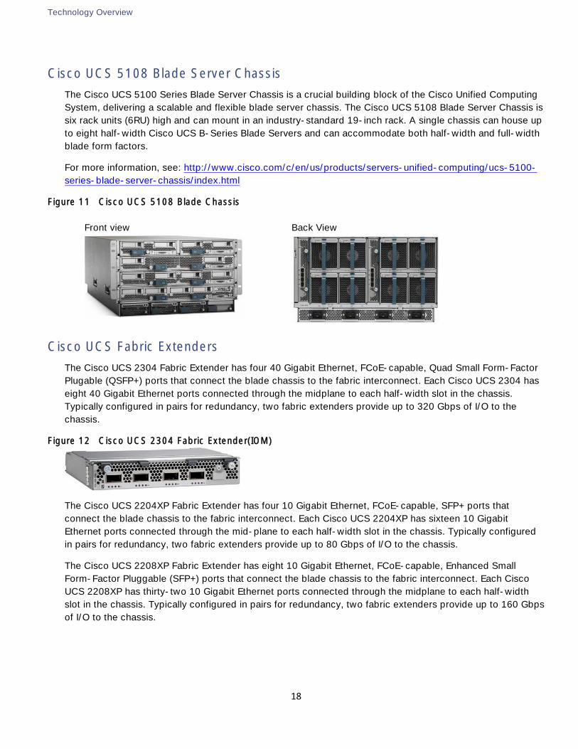
The Cisco UCS 5100 Series Blade Server Chassis is a crucial building block of the Cisco Unified Computing
System, delivering a scalable and flexible blade server chassis. The Cisco UCS 5108 Blade Server Chassis is
six rack units (6RU) high and can mount in an industry-standard 19-inch rack. A single chassis can house up
to eight half-width Cisco UCS B-Series Blade Servers and can accommodate both half-width and full-width
blade form factors.
For more information, see: http://www.cisco.com/c/en/us/products/servers-unified-computing/ucs-5100-
series-blade-server-chassis/index.html
Figure 11 Cisco UCS 5108 Blade Chassis
Front view
Back View
Cisco UCS Fabric Extenders
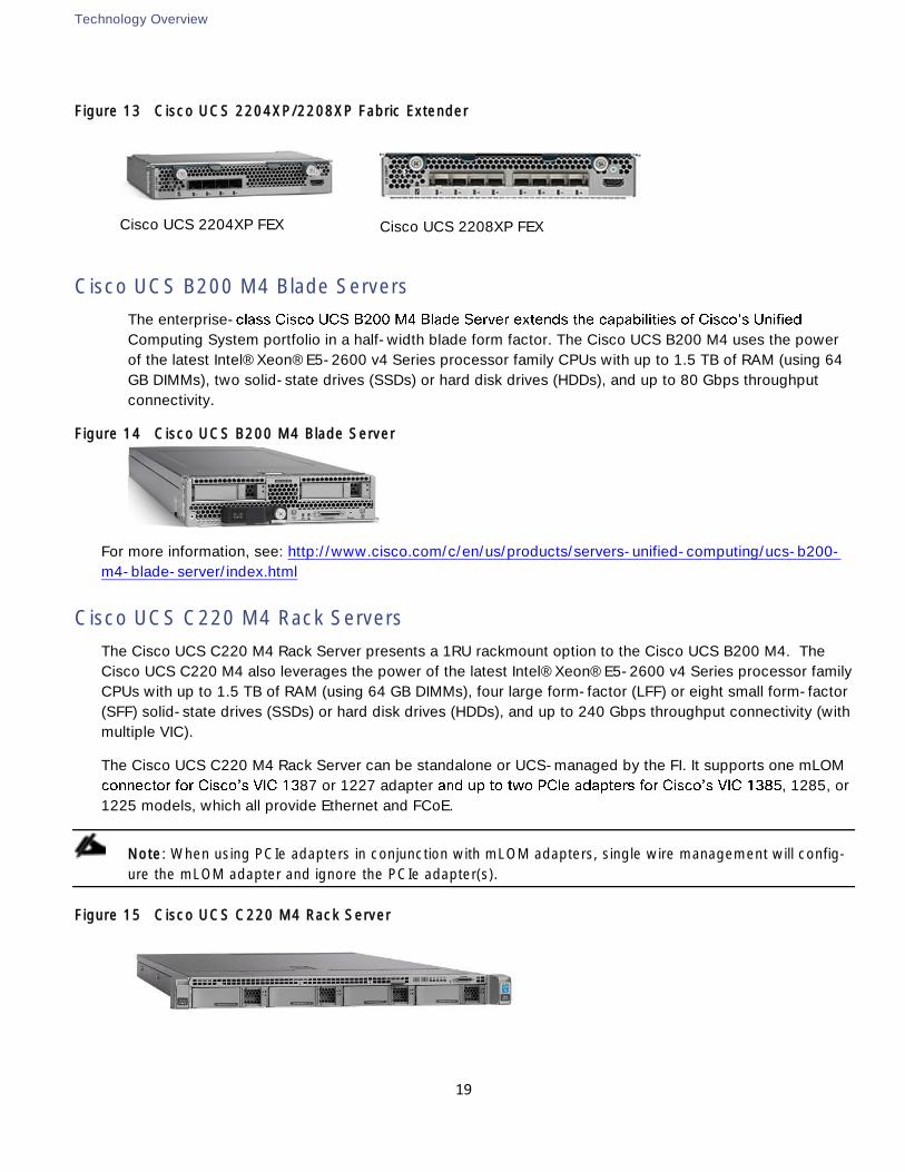
The Cisco UCS 2304 Fabric Extender has four 40 Gigabit Ethernet, FCoE-capable, Quad Small Form-Factor
Plugable (QSFP+) ports that connect the blade chassis to the fabric interconnect. Each Cisco UCS 2304 has
eight 40 Gigabit Ethernet ports connected through the midplane to each half-width slot in the chassis.
Typically configured in pairs for redundancy, two fabric extenders provide up to 320 Gbps of I/O to the
chassis.
Figure 12 Cisco UCS 2304 Fabric Extender(IOM)
The Cisco UCS 2204XP Fabric Extender has four 10 Gigabit Ethernet, FCoE-capable, SFP+ ports that
connect the blade chassis to the fabric interconnect. Each Cisco UCS 2204XP has sixteen 10 Gigabit
Ethernet ports connected through the mid-plane to each half-width slot in the chassis. Typically configured
in pairs for redundancy, two fabric extenders provide up to 80 Gbps of I/O to the chassis.
The Cisco UCS 2208XP Fabric Extender has eight 10 Gigabit Ethernet, FCoE-capable, Enhanced Small
Form-Factor Pluggable (SFP+) ports that connect the blade chassis to the fabric interconnect. Each Cisco
UCS 2208XP has thirty-two 10 Gigabit Ethernet ports connected through the midplane to each half-width
slot in the chassis. Typically configured in pairs for redundancy, two fabric extenders provide up to 160 Gbps
of I/O to the chassis.
Technology Overview
19
Figure 13 Cisco UCS 2204XP/2208XP Fabric Extender
Cisco UCS 2204XP FEX
Cisco UCS 2208XP FEX
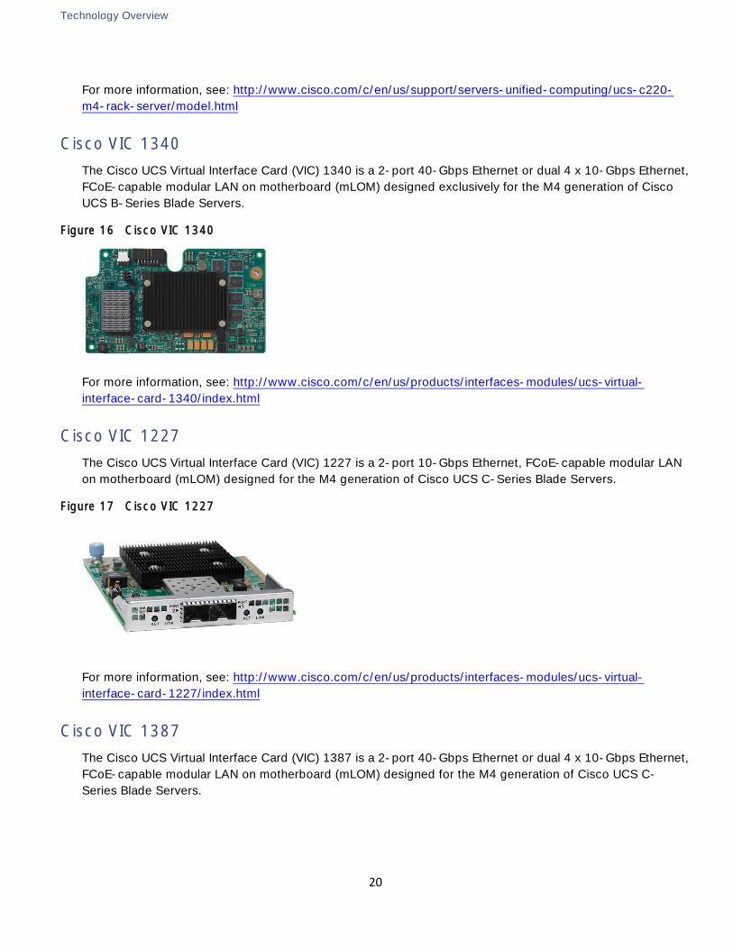
Cisco UCS B200 M4 Blade Servers
The enterprise-
Computing System portfolio in a half-width blade form factor. The Cisco UCS B200 M4 uses the power
of the latest Intel® Xeon® E5-2600 v4 Series processor family CPUs with up to 1.5 TB of RAM (using 64
GB DIMMs), two solid-state drives (SSDs) or hard disk drives (HDDs), and up to 80 Gbps throughput
connectivity.
Figure 14 Cisco UCS B200 M4 Blade Server
For more information, see: http://www.cisco.com/c/en/us/products/servers-unified-computing/ucs-b200-
m4-blade-server/index.html
Cisco UCS C220 M4 Rack Servers
The Cisco UCS C220 M4 Rack Server presents a 1RU rackmount option to the Cisco UCS B200 M4. The
Cisco UCS C220 M4 also leverages the power of the latest Intel® Xeon® E5-2600 v4 Series processor family
CPUs with up to 1.5 TB of RAM (using 64 GB DIMMs), four large form-factor (LFF) or eight small form-factor
(SFF) solid-state drives (SSDs) or hard disk drives (HDDs), and up to 240 Gbps throughput connectivity (with
multiple VIC).
The Cisco UCS C220 M4 Rack Server can be standalone or UCS-managed by the FI. It supports one mLOM
87 or 1227 adapter , 1285, or
1225 models, which all provide Ethernet and FCoE.
Note: When using PCIe adapters in conjunction with mLOM adapters, single wire management will config-
ure the mLOM adapter and ignore the PCIe adapter(s).
Figure 15 Cisco UCS C220 M4 Rack Server
Technology Overview
20
For more information, see: http://www.cisco.com/c/en/us/support/servers-unified-computing/ucs-c220-
m4-rack-server/model.html
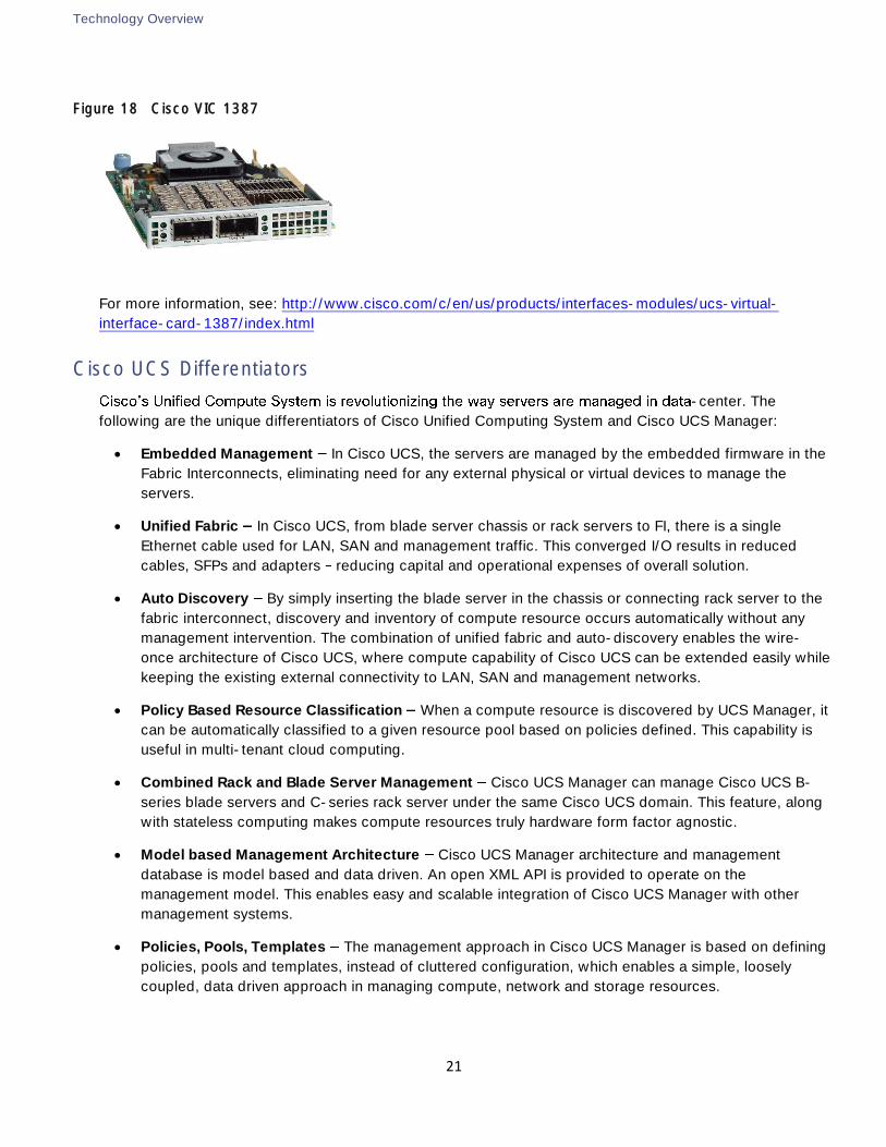
Cisco VIC 1340
The Cisco UCS Virtual Interface Card (VIC) 1340 is a 2-port 40-Gbps Ethernet or dual 4 x 10-Gbps Ethernet,
FCoE-capable modular LAN on motherboard (mLOM) designed exclusively for the M4 generation of Cisco
UCS B-Series Blade Servers.
Figure 16 Cisco VIC 1340
For more information, see: http://www.cisco.com/c/en/us/products/interfaces-modules/ucs-virtual-
interface-card-1340/index.html
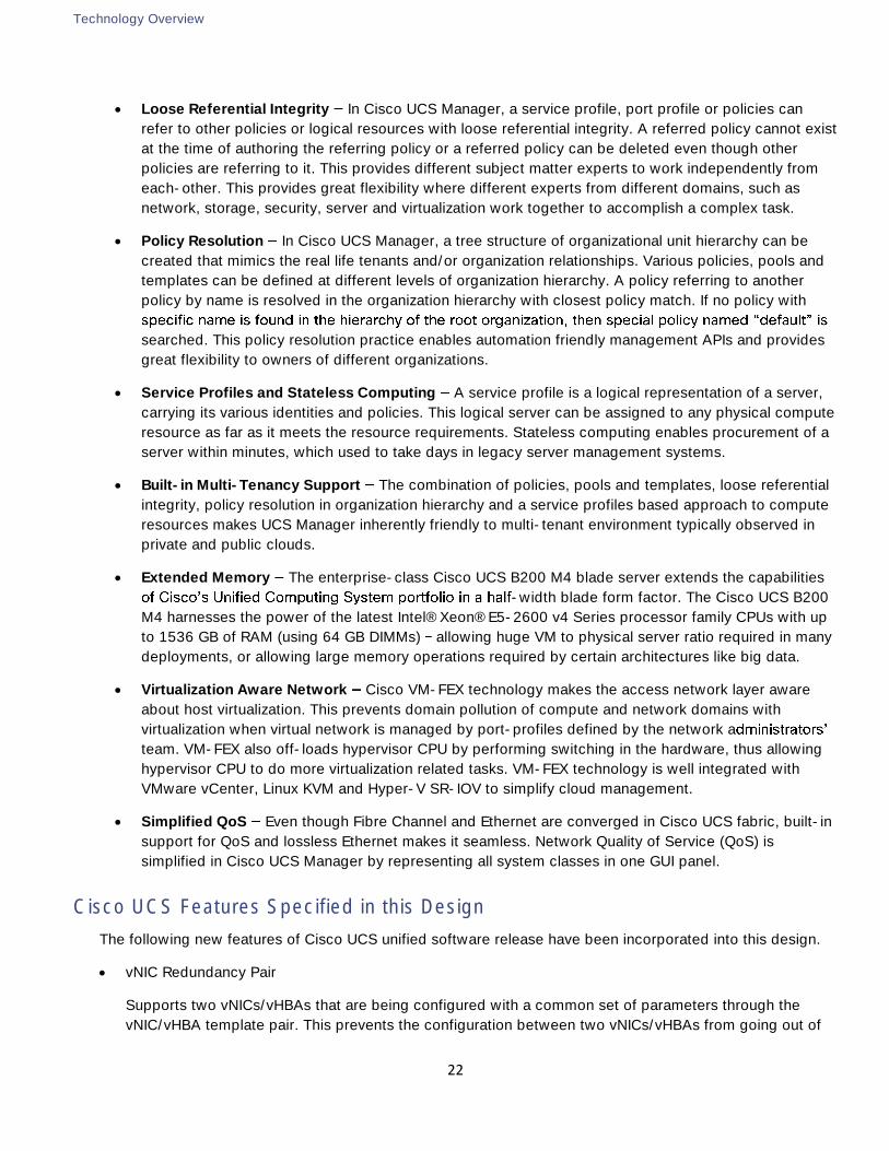
Cisco VIC 1227
The Cisco UCS Virtual Interface Card (VIC) 1227 is a 2-port 10-Gbps Ethernet, FCoE-capable modular LAN
on motherboard (mLOM) designed for the M4 generation of Cisco UCS C-Series Blade Servers.
Figure 17 Cisco VIC 1227
For more information, see: http://www.cisco.com/c/en/us/products/interfaces-modules/ucs-virtual-
interface-card-1227/index.html
Cisco VIC 1387
The Cisco UCS Virtual Interface Card (VIC) 1387 is a 2-port 40-Gbps Ethernet or dual 4 x 10-Gbps Ethernet,
FCoE-capable modular LAN on motherboard (mLOM) designed for the M4 generation of Cisco UCS C-
Series Blade Servers.
Technology Overview
21
Figure 18 Cisco VIC 1387
For more information, see: http://www.cisco.com/c/en/us/products/interfaces-modules/ucs-virtual-
interface-card-1387/index.html
Cisco UCS Differentiators
-center. The
following are the unique differentiators of Cisco Unified Computing System and Cisco UCS Manager:
Embedded Management In Cisco UCS, the servers are managed by the embedded firmware in the
Fabric Interconnects, eliminating need for any external physical or virtual devices to manage the
servers.
Unified Fabric In Cisco UCS, from blade server chassis or rack servers to FI, there is a single
Ethernet cable used for LAN, SAN and management traffic. This converged I/O results in reduced
cables, SFPs and adapters reducing capital and operational expenses of overall solution.
Auto Discovery By simply inserting the blade server in the chassis or connecting rack server to the
fabric interconnect, discovery and inventory of compute resource occurs automatically without any
management intervention. The combination of unified fabric and auto-discovery enables the wire-
once architecture of Cisco UCS, where compute capability of Cisco UCS can be extended easily while
keeping the existing external connectivity to LAN, SAN and management networks.
Policy Based Resource Classification When a compute resource is discovered by UCS Manager, it
can be automatically classified to a given resource pool based on policies defined. This capability is
useful in multi-tenant cloud computing.
Combined Rack and Blade Server Management Cisco UCS Manager can manage Cisco UCS B-
series blade servers and C-series rack server under the same Cisco UCS domain. This feature, along
with stateless computing makes compute resources truly hardware form factor agnostic.
Model based Management Architecture Cisco UCS Manager architecture and management
database is model based and data driven. An open XML API is provided to operate on the
management model. This enables easy and scalable integration of Cisco UCS Manager with other
management systems.
Policies, Pools, Templates The management approach in Cisco UCS Manager is based on defining
policies, pools and templates, instead of cluttered configuration, which enables a simple, loosely
coupled, data driven approach in managing compute, network and storage resources.
Technology Overview
22
Loose Referential Integrity In Cisco UCS Manager, a service profile, port profile or policies can
refer to other policies or logical resources with loose referential integrity. A referred policy cannot exist
at the time of authoring the referring policy or a referred policy can be deleted even though other
policies are referring to it. This provides different subject matter experts to work independently from
each-other. This provides great flexibility where different experts from different domains, such as
network, storage, security, server and virtualization work together to accomplish a complex task.
Policy Resolution In Cisco UCS Manager, a tree structure of organizational unit hierarchy can be
created that mimics the real life tenants and/or organization relationships. Various policies, pools and
templates can be defined at different levels of organization hierarchy. A policy referring to another
policy by name is resolved in the organization hierarchy with closest policy match. If no policy with
searched. This policy resolution practice enables automation friendly management APIs and provides
great flexibility to owners of different organizations.
Service Profiles and Stateless Computing A service profile is a logical representation of a server,
carrying its various identities and policies. This logical server can be assigned to any physical compute
resource as far as it meets the resource requirements. Stateless computing enables procurement of a
server within minutes, which used to take days in legacy server management systems.
Built-in Multi-Tenancy Support The combination of policies, pools and templates, loose referential
integrity, policy resolution in organization hierarchy and a service profiles based approach to compute
resources makes UCS Manager inherently friendly to multi-tenant environment typically observed in
private and public clouds.
Extended Memory The enterprise-class Cisco UCS B200 M4 blade server extends the capabilities
-width blade form factor. The Cisco UCS B200
M4 harnesses the power of the latest Intel® Xeon® E5-2600 v4 Series processor family CPUs with up
to 1536 GB of RAM (using 64 GB DIMMs) allowing huge VM to physical server ratio required in many
deployments, or allowing large memory operations required by certain architectures like big data.
Virtualization Aware Network Cisco VM-FEX technology makes the access network layer aware
about host virtualization. This prevents domain pollution of compute and network domains with
virtualization when virtual network is managed by port-profiles defined by the network a
team. VM-FEX also off-loads hypervisor CPU by performing switching in the hardware, thus allowing
hypervisor CPU to do more virtualization related tasks. VM-FEX technology is well integrated with
VMware vCenter, Linux KVM and Hyper-V SR-IOV to simplify cloud management.
Simplified QoS Even though Fibre Channel and Ethernet are converged in Cisco UCS fabric, built-in
support for QoS and lossless Ethernet makes it seamless. Network Quality of Service (QoS) is
simplified in Cisco UCS Manager by representing all system classes in one GUI panel.
Cisco UCS Features Specified in this Design
The following new features of Cisco UCS unified software release have been incorporated into this design.
vNIC Redundancy Pair
Supports two vNICs/vHBAs that are being configured with a common set of parameters through the
vNIC/vHBA template pair. This prevents the configuration between two vNICs/vHBAs from going out of
Technology Overview
23
sync. Multiple vNIC/vHBA pairs can be created from the same vNIC/vHBA template pair. Only vNIC
redundancy pairs were used in this validation since the vHBAs were each assigned a different VSAN.
HTML 5 User Interface Improvements
Introduced the redesigned Cisco UCS Manager HTML 5 user interface to facilitate improved
management of the Cisco UCS Manager ecosystem.
40 GE Link Quality
Cisco UCS Manager 3.1(2) introduces the capability to detect and alert users to issues relating to 40Gb
link quality.
Cisco Nexus 9000 Series Switch
The Cisco Nexus 9000 Series Switches offer both modular and fixed 10/25/40/50/100 Gigabit Ethernet
switch configurations with scalability up to 60 Tbps of non-blocking performance with less than five-
microsecond latency, non-blocking Layer 2 and Layer 3 Ethernet ports and wire speed VXLAN gateway,
bridging, and routing support.
FlexPod and Cisco 9000 Modes of Operation
The Cisco Nexus 9000 Series delivers proven high performance and density, low latency, and exceptional
power efficiency in a broad range of compact form factors. Operating in Cisco NX-OS Software mode or in
Application Centric Infrastructure(ACI) mode, these switches address traditional or fully automated data
center deployments.
The 9000 Series offers modular 9500 switches and fixed 9300 and 9200 switches with 1/10/25/50/40/100
Gigabit Ethernet switch configurations. 9200 switches are optimized for high performance and density in NX-
OS mode operations. The 9500 and 9300 are optimized to deliver increased operational flexibility in:
NX-OS mode for traditional architectures and consistency across Nexus switches, or
ACI mode to take advantage of ACI's policy-driven services and infrastructure automation features
Cisco Nexus 9000 NX-OS stand-alone mode FlexPod design consists of a single pair of Nexus 9000 top of
rack switches. The traditional deployment model delivers:
High performance and scalability with L2 and L3 support per port
Virtual Extensible LAN (VXLAN) support at line rate
Hardware and software high availability with
Cisco In-Service Software Upgrade (ISSU) promotes high availability and faster upgrades
Virtual port-channel (vPC) technology provides Layer 2 multipathing with all paths forwarding
Advanced reboot capabilities include hot and cold patching
The switches use hot-swappable power-supply units (PSUs) and fans with N+1 redundancy
Technology Overview
24
Purpose-built Cisco NX-OS Software operating system with comprehensive, proven innovations such
as open programmability, Cisco NX-API and POAP
When leveraging ACI fabric mode, the Nexus switches are deployed in a spine-leaf architecture. Although
the reference architecture covered in this document does not leverage ACI, it lays the foundation for
customer migration to ACI by leveraging the Nexus 9000 switches.
Application Centric Infrastructure (ACI) is a holistic architecture with centralized automation and policy-
driven application profiles. ACI delivers software flexibility with the scalability of hardware performance. Key
characteristics of ACI include:
Simplified automation by an application-driven policy model
Centralized visibility with real-time, application health monitoring
Open software flexibility for DevOps teams and ecosystem partner integration
Scalable performance and multi-tenancy in hardware
Networking with ACI is about providing a network that is deployed, monitored, and managed in a fashion that
supports DevOps and rapid application change. ACI does so through the reduction of complexity and a
common policy framework that can automate provisioning and managing of resources.
For more information, refer to: http://www.cisco.com/c/en/us/products/switches/nexus-9000-series-
switches/index.html.
The Cisco Nexus 9372PX Switch, used in this validation, provides a line-rate layer 2 and layer 3 feature set
in a compact form factor. It offers a flexible switching platform for both 3-tier and spine-leaf architectures as
a leaf node. With the option to operate in Cisco NX-OS or Application Centric Infrastructure (ACI) mode, it
can be deployed in small business, enterprise, and service provider architectures.
Cisco MDS 9000 Series Multilayer SAN Switches
Cisco MDS 9000 Series Multilayer SAN Switches can help lower the total cost of ownership (TCO) of storage
environments. By combining robust, flexible hardware architecture with multiple layers of network and
storage-management intelligence, the Cisco MDS 9000 Series helps you build highly available, scalable
storage networks with advanced security and unified management.
The Cisco MDS 9148S 16G Multilayer Fabric Switch, used in this validation, is the next generation of the
highly reliable Cisco MDS 9100 Series Switches. It includes up to 48 auto-sensing line-rate 16-Gbps Fibre
Channel ports in a compact easy to deploy and manage 1-rack-unit (1RU) form factor. In all, the Cisco MDS
9148S is a powerful and flexible switch that delivers high performance and comprehensive Enterprise-class
features at an affordable price.
VMware vSphere
VMware vSphere is a virtualization platform for holistically managing large collections of infrastructure
(resources-CPUs, storage and networking) as a seamless, versatile, and dynamic operating environment.
Unlike traditional operating systems that manage an individual machine, VMware vSphere aggregates the
infrastructure of an entire data center to create a single powerhouse with resources that can be allocated
quickly and dynamically to any application in need.
Technology Overview
25
Among the changes new in vSphere 6.0 U2 used in this design, there is a new HTML 5 installer supporting
options for install and upgrade of vCenter Server. Also included is a new Appliance Management user
interface and a UI option for the Platform Services Controller. Additionally, an ESXi host web-based
configuration utility is used for initial setup of VMware ESXi.
For more information, refer to: http://www.vmware.com/products/datacenter-
virtualization/vsphere/overview.html
NetApp FAS and ONTAP 9
NetApp solutions offer increased availability while consuming fewer IT resources. A NetApp solution includes
hardware in the form of controllers and disk storage that run the ONTAP data management software. Two
types of NetApp FAS controllers are currently available: FAS and All Flash FAS. FAS disk storage is offered
in three configurations: serial attached SCSI (SAS), serial ATA (SATA), and solid state drives (SSD). All Flash
FAS systems are built exclusively with SSDs.
With the NetApp portfolio, you can select the controller and disk storage configuration that best suits your
requirements. The storage efficiency built into NetApp ONTAP provides substantial space savings and allows
you to store more data at a lower cost on FAS and All Flash FAS platforms.
NetApp offers a unified storage architecture that simultaneously supports a storage area network (SAN) and
network-attached storage (NAS) across many operating environments, including VMware, Windows, and
UNIX. This single architecture provides access to data with industry-standard protocols, including NFS, CIFS,
iSCSI, Fibre Channel (FC), and Fibre Channel over Ethernet (FCoE). Connectivity options include standard
Ethernet (10/100/1000MbE or 10GbE) and FC (4, 8, or 16Gb/sec).
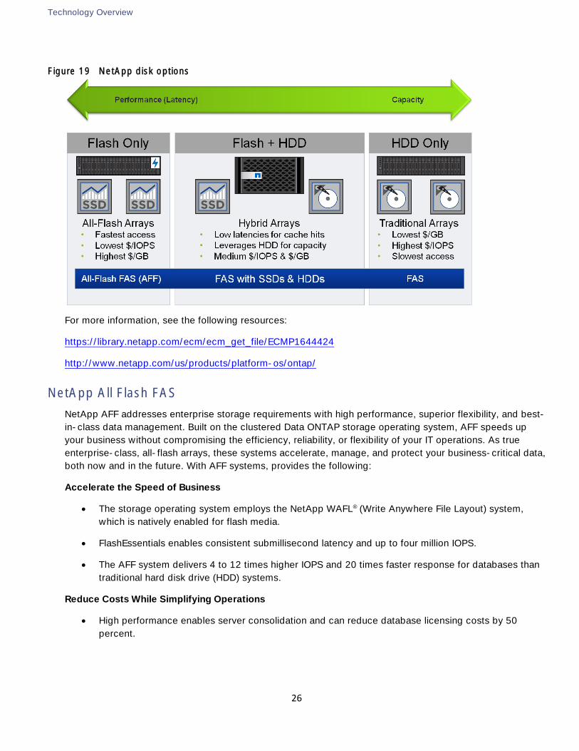
In addition, all systems can be configured with high-performance SSD or SAS disks for primary storage
applications, low-cost SATA disks for secondary applications (such as backup and archive), or a mix of
different disk types. See the NetApp disk options available in 0. Note that All Flash FAS configurations can
only support SSDs. A hybrid cluster with a mix of All Flash FAS HA pairs and FAS HA pairs with HDDs and/or
SSDs is also supported.
Technology Overview
26
Figure 19 NetApp disk options
For more information, see the following resources:
https://library.netapp.com/ecm/ecm_get_file/ECMP1644424
http://www.netapp.com/us/products/platform-os/ontap/
NetApp All Flash FAS
NetApp AFF addresses enterprise storage requirements with high performance, superior flexibility, and best-
in-class data management. Built on the clustered Data ONTAP storage operating system, AFF speeds up
your business without compromising the efficiency, reliability, or flexibility of your IT operations. As true
enterprise-class, all-flash arrays, these systems accelerate, manage, and protect your business-critical data,
both now and in the future. With AFF systems, provides the following:
Accelerate the Speed of Business
The storage operating system employs the NetApp WAFL® (Write Anywhere File Layout) system,
which is natively enabled for flash media.
FlashEssentials enables consistent submillisecond latency and up to four million IOPS.
The AFF system delivers 4 to 12 times higher IOPS and 20 times faster response for databases than
traditional hard disk drive (HDD) systems.
Reduce Costs While Simplifying Operations
High performance enables server consolidation and can reduce database licensing costs by 50
percent.
Technology Overview
27
-flash storage solution that supports synchronous replication, AFF
supports all your backup and recovery needs with a complete suite of integrated data-protection
utilities.
Data-reduction technologies can deliver space savings of five to ten times on average.
Newly enhanced inline compression delivers near-zero performance effect. Incompressible data
detection eliminates wasted cycles. Inline compression is enabled by default on all volumes in AFF
running Data ONTAP 8.3.1 and later.
Always-on deduplication runs continuously in the background and provides additional space savings
for use cases such as virtual desktop deployments.
Inline deduplication accelerates VM provisioning.
Advanced SSD partitioning increases usable capacity by almost 20 percent.
Future-proof your Investment with Deployment Flexibility
AFF systems are ready for the data fabric. Data can move between the performance and capacity
tiers on premises or in the cloud.
AFF offers application and ecosystem integration for virtual desktop integration (VDI), database, and
server virtualization.
Without silos, you can nondisruptively scale-out and move workloads between Flash and HDD within
a cluster.
NetApp ONTAP 9
With NetApp ONTAP 9, NetApp brings forward the next level of enterprise data management. Using ONTAP
9, enterprises can quickly integrate the best of traditional and emerging technologies, incorporating flash,
the cloud, and software-defined architectures to build a data-fabric foundation across on-premises and
cloud resources. ONTAP 9 software is optimized for flash and provides many features to improve
performance, storage efficiency, and usability.
For more information about ONTAP 9, see the ONTAP 9 documentation center:
http://docs.netapp.com/ontap-9/index.jsp
Storage Efficiency
Storage efficiency has always been a primary architectural design point of clustered Data ONTAP. A wide
array of features allows businesses to store more data using less space. In addition to deduplication and
compression, businesses can store their data more efficiently using features such as unified storage, multi-
tenancy, thin provisioning, and NetApp Snapshot® copies.
Starting with ONTAP 9, NetApp guarantees that the use of NetApp storage efficiency technologies on AFF
systems reduce the total logical capacity used to store customer data by 75 percent, a data reduction ratio
of 4:1. This space reduction is a combination of several different technologies, such as deduplication,
compression, and compaction, which provide additional reduction to the basic features provided by ONTAP.
Technology Overview
28
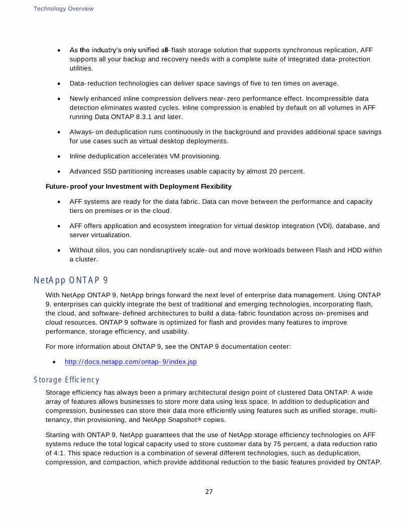
Compaction, which is introduced in ONTAP 9, is the latest patented storage efficiency technology released
by NetApp. In the ONTAP WAFL file system, all I/O takes up 4KB of space, even if it does not actually require
4KB of data. Compaction combines multiple blocks that are not using their full 4KB of space together into
one block. This one block can be more efficiently stored on the disk-to-save space. This process can be
seen in Figure 20.
Figure 20 ONTAP 9 - Compaction
For more information about compaction and the 3-4-5 Flash Advantage Program in ONTAP 9, see the
following links:
NetApp Data Compression, Deduplication, and Data Compaction
http://www.netapp.com/us/media/tr-4476.pdf
http://www.netapp.com/us/forms/sales-inquiry/flash-3-4-5-promotion.aspx
RAID-TEC
With ONTAP 9, NetApp became the first storage vendor to introduce support for 15.3TB SSDs. These large
drives dramatically reduce the physical space it takes to rack, power, and cool infrastructure equipment.
Unfortunately, as drive sizes increase, so does the time it takes to reconstruct a raid group after a disk
failure. While the NetApp RAID DP® storage protection technology offers much more protection than RAID 4,
it is more vulnerable than usual to additional disk failure during reconstruction of a RAID group with large
disks.
To provide additional protection to RAID groups that contain large disk drives, ONTAP 9 introduces RAID
with triple erasure encoding (RAID-TEC). RAID-TEC provides a third parity disk in addition to the two that are
present in RAID DP. This third parity disk offers additional redundancy to a raid group, allowing up to three
disks in the raid group to fail. Because of the third parity drive present in RAID-TEC RAID groups, the size of
the raid group can be increased. Because of this increase in RAID group size, the percentage of a RAID
group taken up by parity drives is no different than the percentage for a RAID DP aggregate.
RAID-TEC is available as a RAID type for aggregates made of any disk type or size. It is the default RAID
type when creating an aggregate with SATA disks that are 6TB or larger, and it is the mandatory RAID type
with SATA disks that are 10TB or larger, except when they are used in root aggregates. Most importantly,
Technology Overview
29
because of the WAFL format built into ONTAP, RAID-TEC provides the additional protection of a third parity
drive without incurring a significant write penalty over RAID 4 or RAID DP.
For more information on RAID-TEC, see the Disks and Aggregates Power Guide:
https://library.netapp.com/ecm/ecm_download_file/ECMLP2496263
Root-Data-Data Disk Partitioning
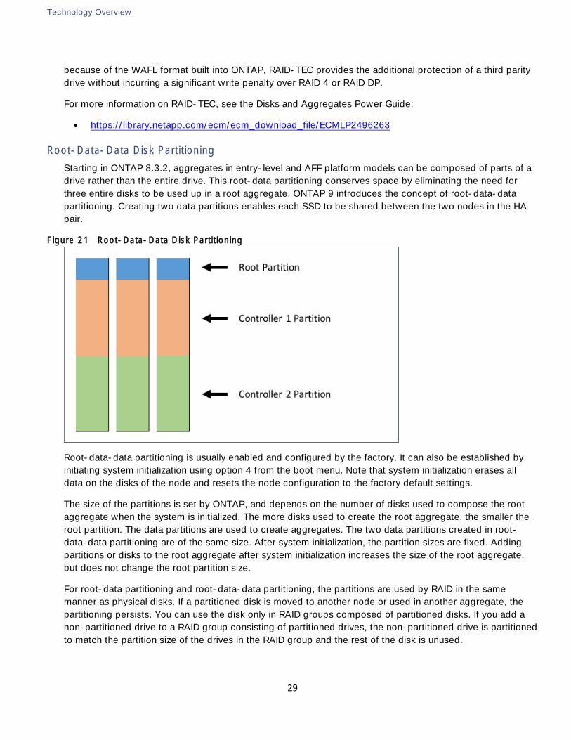
Starting in ONTAP 8.3.2, aggregates in entry-level and AFF platform models can be composed of parts of a
drive rather than the entire drive. This root-data partitioning conserves space by eliminating the need for
three entire disks to be used up in a root aggregate. ONTAP 9 introduces the concept of root-data-data
partitioning. Creating two data partitions enables each SSD to be shared between the two nodes in the HA
pair.
Figure 21 Root-Data-Data Disk Partitioning
Root-data-data partitioning is usually enabled and configured by the factory. It can also be established by
initiating system initialization using option 4 from the boot menu. Note that system initialization erases all
data on the disks of the node and resets the node configuration to the factory default settings.
The size of the partitions is set by ONTAP, and depends on the number of disks used to compose the root
aggregate when the system is initialized. The more disks used to create the root aggregate, the smaller the
root partition. The data partitions are used to create aggregates. The two data partitions created in root-
data-data partitioning are of the same size. After system initialization, the partition sizes are fixed. Adding
partitions or disks to the root aggregate after system initialization increases the size of the root aggregate,
but does not change the root partition size.
For root-data partitioning and root-data-data partitioning, the partitions are used by RAID in the same
manner as physical disks. If a partitioned disk is moved to another node or used in another aggregate, the
partitioning persists. You can use the disk only in RAID groups composed of partitioned disks. If you add a
non-partitioned drive to a RAID group consisting of partitioned drives, the non-partitioned drive is partitioned
to match the partition size of the drives in the RAID group and the rest of the disk is unused.
Technology Overview
30
NetApp Storage Virtual Machines
A cluster serves data through at least one and possibly multiple storage virtual machines (SVMs; formerly
called Vservers). An SVM is a logical abstraction that represents the set of physical resources of the cluster.
Data volumes and network logical interfaces (LIFs) are created and assigned to an SVM and may reside on
any node in the cluster to which the SVM has been given access. An SVM may own resources on multiple
nodes concurrently, and those resources can be moved nondisruptively from one node to another. For
example, a flexible volume can be nondisruptively moved to a new node and aggregate, or a data LIF can be
transparently reassigned to a different physical network port. The SVM abstracts the cluster hardware and it
is not tied to any specific physical hardware.
An SVM can support multiple data protocols concurrently. Volumes within the SVM can be joined together to
form a single NAS namespace, which makes all of an SVM's data available through a single share or mount
point to NFS and CIFS clients. SVMs also support block-based protocols, and LUNs can be created and
exported by using iSCSI, FC, or FCoE. Any or all of these data protocols can be configured for use within a
given SVM.
Because it is a secure entity, an SVM is only aware of the resources that are assigned to it and has no
knowledge of other SVMs and their respective resources. Each SVM operates as a separate and distinct
entity with its own security domain. Tenants can manage the resources allocated to them through a
delegated SVM administration account. Each SVM can connect to unique authentication zones such as
Active Directory, LDAP, or NIS. A NetApp cluster can contain multiple SVMs. If you have multiple SVMs, you
can delegate an SVM to a specific application. This allows administrators of the application to access only
the dedicated SVMs and associated storage, increasing manageability and reducing risk.
IPspaces in ONTAP 9
An IPspace defines a distinct IP address space for different SVMs. Ports and IP addresses defined for an
IPspace are accessible only within that IPspace. A distinct routing table is maintained for each SVM within an
IPspace. Therefore, no cross-SVM or cross-IP-space traffic routing occurs.
IPspaces enable you to configure a single ONTAP cluster so that it can be accessed by clients from more
than one administratively separate network domain, even when those clients are using the same IP address
subnet range. This allows the separation of client traffic for privacy and security.
Domain and Element Management
This section provides general descriptions of the domain and element managers used during the validation
effort. The following managers were used:
Cisco UCS Manager
Cisco UCS Performance Manager
Cisco Virtual Switch Update Manager
r
NetApp OnCommand® System and Unified Manager
NetApp Virtual Storage Console (VSC)
Technology Overview
31
NetApp OnCommand Performance Manager
NetApp SnapManager® and SnapDrive® software
Cisco Unified Computing System Manager
Cisco UCS Manager provides unified, centralized, embedded management of all Cisco Unified Computing
System software and hardware components across multiple chassis and thousands of virtual machines.
Administrators use the software to manage the entire Cisco Unified Computing System as a single logical
entity through an intuitive GUI, a command-line interface (CLI), or an XML API.
The Cisco UCS Manager resides on a pair of Cisco UCS 6300 or 6200 Series Fabric Interconnects using a
clustered, active-standby configuration for high availability. The software gives administrators a single
interface for performing server provisioning, device discovery, inventory, configuration, diagnostics,
monitoring, fault detection, auditing, and statistics collection. Cisco UCS Manager service profiles and
templates support versatile role- and policy-based management, and system configuration information can
be exported to configuration management databases (CMDBs) to facilitate processes based on IT
Infrastructure Library (ITIL) concepts. Service profiles benefit both virtualized and non-virtualized
environments and increase the mobility of non-virtualized servers, such as when moving workloads from
server to server or taking a server offline for service or upgrade. Profiles can be used in conjunction with
virtualization clusters to bring new resources online easily, complementing existing virtual machine mobility.
For more information on Cisco UCS Manager, click the following link:
http://www.cisco.com/en/US/products/ps10281/index.html
Cisco UCS Performance Manager
With technology from Zenoss, Cisco UCS Performance Manager delivers detailed monitoring from a single
customizable console. The software uses APIs from Cisco UCS Manager and other Cisco® and third-party
components to collect data and display comprehensive, relevant information about your Cisco UCS
integrated infrastructure.
Cisco UCS Performance Manager does the following:
Unifies performance monitoring and management of Cisco UCS integrated infrastructure
Delivers real-time views of fabric and data center switch bandwidth use and capacity thresholds
Discovers and creates relationship models of each system, giving your staff a single, accurate view of
all components
Provides coverage for Cisco UCS servers, Cisco networking, vendor storage, hypervisors, and
operating systems
Allows you to easily navigate to individual components for rapid problem resolution
For more information on Cisco Performance Manager, click the following link:
http://www.cisco.com/c/en/us/products/servers-unified-computing/ucs-performance-manager/index.html
Technology Overview
32
Cisco Virtual Switch Update Manager (VSUM) (Optional)
Cisco VSUM is a virtual appliance that is registered as a plug-in to the VMware vCenter Server. Cisco VSUM
simplifies the installation and configuration of the optional Cisco Nexus 1000v. If Cisco Nexus 1000V is not
used in the infrastructure, the VSUM is not needed. Some of the key benefits of Cisco VSUM are:
Install the Cisco Nexus 1000V switch
Migrate the VMware vSwitch and VMware vSphere Distributed Switch (VDS) to the Cisco Nexus
1000V
Monitor the Cisco Nexus 1000V
Upgrade the Cisco Nexus 1000V and add hosts from an earlier version to the latest version
Install the Cisco Nexus 1000V license
View the health of the virtual machines in your data center using the Dashboard - Cisco Nexus 1000V
Upgrade from an earlier release to Cisco VSUM 2.0
For more information on Cisco VSUM, click the following link:
http://www.cisco.com/c/en/us/td/docs/switches/datacenter/nexus1000/vsum/2-0/release_notes/n1K-
vsum-2-0.html
VMware vCenter Server
VMware vCenter Server is the simplest and most efficient way to manage VMware vSphere, irrespective of
the number of VMs you have. It provides unified management of all hosts and VMs from a single console and
aggregates performance monitoring of clusters, hosts, and VMs. VMware vCenter Server gives
administrators a deep insight into the status and configuration of compute clusters, hosts, VMs, storage, the
guest OS, and other critical components of a virtual infrastructure.
New to vCenter Server 6.0 is the Platform Services Controller (PSC). The PSC serves as a centralized
repository for information which is shared between vCenters such as vCenter Single Sign-On, licensing
information, and certificate management. This introduction of the PSC also enhances vCenter Linked mode,
allowing both vCenter Windows based deployments and vCenter Server Appliance based deployments to
exist in the same vCenter Single Sign-On domain. The vCenter Server Appliance now supports the same
amount of infrastructure as the Windows Based installation, up to 1,000 hosts, 10,000 powered on virtual
machines, 64 clusters, and 8,000 virtual machines per cluster. The PSC can be deployed on the same
machine as vCenter, or as a standalone machine for future scalability.
For more information, click the following link:
http://www.vmware.com/products/vcenter-server/overview.html
NetApp OnCommand System and Unified Manager
With NetApp OnCommand System Manager, storage administrators can manage individual storage systems
or clusters of storage systems. Its easy-to-use interface simplifies common storage administration tasks
such as creating volumes, LUNs, qtrees, shares, and exports, saving time and helping to prevent errors.
Technology Overview
33
System Manager works across all NetApp storage systems. NetApp OnCommand Unified Manager
complements the features of System Manager by enabling the monitoring and management of storage within
the NetApp storage infrastructure.
This solution uses both OnCommand System Manager and OnCommand Unified Manager to provide storage
provisioning and monitoring capabilities within the infrastructure.
For more information, click the following link:
http://www.netapp.com/us/products/management-software/
NetApp OnCommand Performance Manager
OnCommand Performance Manager provides performance monitoring and incident root-cause analysis of
systems running ONTAP. It is the performance management part of OnCommand Unified Manager.
Performance Manager helps you identify workloads that are overusing cluster components and decreasing
the performance of other workloads on the cluster. It alerts you to these performance events (called
incidents), so that you can take corrective action and return to normal operation. You can view and analyze
incidents in the Performance Manager GUI or view them on the Unified Manager Dashboard.
NetApp Virtual Storage Console
The NetApp Virtual Storage Console (VSC) software delivers storage configuration and monitoring, datastore
provisioning, VM cloning, and backup and recovery of VMs and datastores. VSC also includes an application
programming interface (API) for automated control.
VSC is a single VMware vCenter Server plug-in that provides end-to-end VM lifecycle management for
VMware environments that use NetApp storage. VSC is available to all VMware vSphere Clients that connect
to the vCenter Server. This availability is different from a client-side plug-in that must be installed on every
VMware vSphere Client. The VSC software can be installed either on the vCenter Server (if it is Microsoft
Windows-based) or on a separate Microsoft Windows Server instance or VM.
NetApp SnapManager and SnapDrive
NetApp SnapManager® storage management software and NetApp SnapDrive® data management software
are used to provision and back up storage for applications in this solution. The portfolio of SnapManager
products is specific to the particular application. SnapDrive is a common component used with all of the
SnapManager products.
To create a backup, SnapManager interacts with the application to put the application data in an appropriate
state so that a consistent NetApp Snapshot® copy of that data can be made. It then directs SnapDrive to
interact with the storage system SVM and create the Snapshot copy, effectively backing up the application
data. In addition to managing Snapshot copies of application data, SnapDrive can be used to accomplish the
following tasks:
Provisioning application data LUNs in the SVM as mapped disks on the application VM
Managing Snapshot copies of application VMDK disks on NFS or VMFS datastores

Technology Overview
34
Snapshot copy management of application data LUNs is handled by the interaction between SnapDrive and
the SVM management LIF.
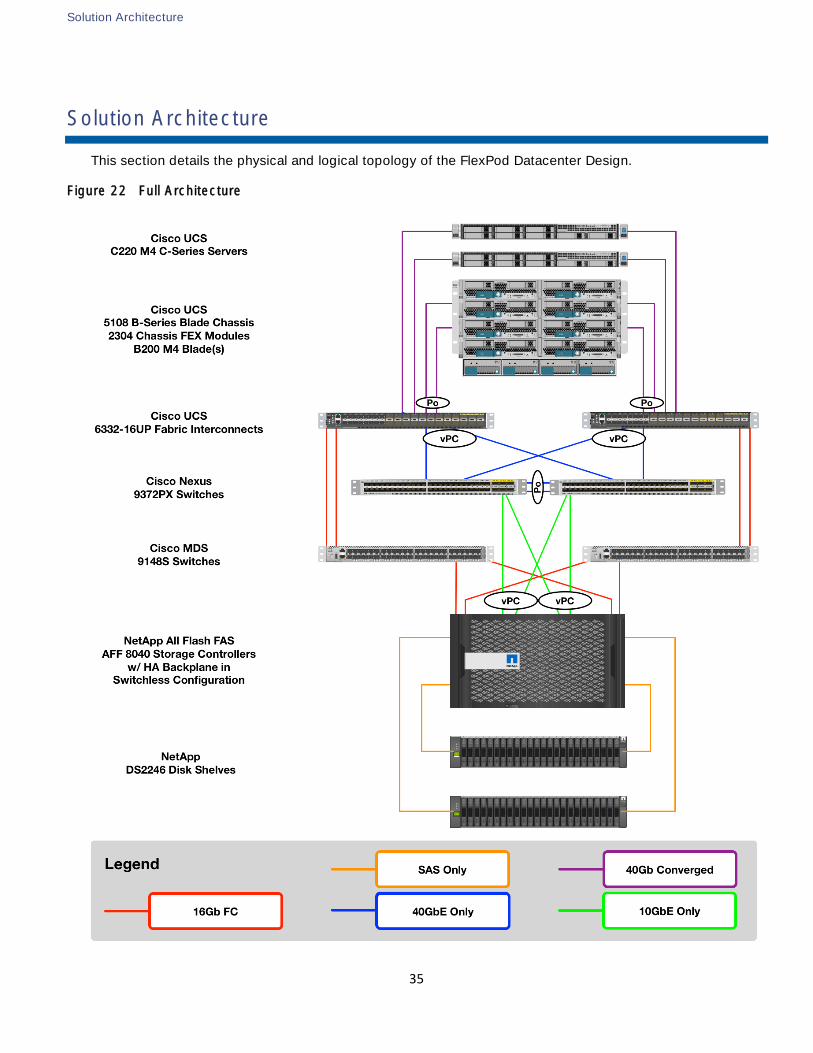
Solution Architecture
35
Solution Architecture
This section details the physical and logical topology of the FlexPod Datacenter Design.
Figure 22 Full Architecture
Solution Architecture
36
Figure 22 details the FlexPod Datacenter Design, which is fully redundant in the compute, network, and
storage layers. There is no single point of failure from a device or traffic path perspective.
Note: While the connectivity shown in Error! Reference source not found. represents a Cisco UCS 6300
Fabric Interconnect based layout, the Cisco UCS 6200 Fabric Interconnect layout will use nearly identical
connections, with the primary differences being the port capacity 40GbE versus 10GbE, and the 16Gb FC
connections will instead be 8Gb FC.
As illustrated, the FlexPod Datacenter Design for Fibre Channel (FC) is an end-to-end storage solution that
supports SAN access using FC. The solution provides redundant 16Gb FC fabrics of Cisco MDS SAN
switches in addition to a 40GbE-enabled fabric, defined by Ethernet uplinks from the Cisco UCS Fabric
Interconnects and NetApp storage devices connected to the Cisco Nexus switches. FC SAN traffic passes
from the NetApp AFF storage controllers to the Cisco MDS switches and finally to the Fabric Interconnect.
The fabric interconnects in this topology are in fibre channel end-host mode and the fibre channel zoning is
done in the MDS switches. This topology allows additional UCS domains to be attached to the MDS switches
and share the FC storage. This topology can also be used to attach the FlexPod to an existing SAN.
What is not shown in Figure 22 is this design with the storage attached directly to the fabric interconnects.
In this topology, the fabric interconnects are in fibre channel switching mode and the zoning is done in the
fabric interconnects. It is possible to migrate from the direct connect topology to the MDS topology by
adding uplinks to the MDS switches. When uplinks are added, it is not supported to do the zoning in the
fabric interconnects. The zoning must be done in the MDS switches and pushed into the fabric
interconnects. When fibre channel storage ports are used on the fabric interconnects, the fabric
interconnects must be in fibre channel switching mode and the links between the fabric interconnects and
the fabric interconnects or migrate it to the MDS switches. If the migration to the MDS switches is done, the
fabric interconnects can either be left in fibre channel switching mode or returned to fibre channel end-host
mode. If the fabric interconnect is in fibre channel end-host mode, the MDS ports are fibre channel F ports.
Link aggregation technologies play an important role, providing improved aggregate bandwidth and link
resiliency across the solution stack. The NetApp storage controllers, Cisco Unified Computing System, and
Cisco Nexus 9000 platforms support active port channeling using 802.3ad standard Link Aggregation
Control Protocol (LACP). Port channeling is a link aggregation technique offering link fault tolerance and
traffic distribution (load balancing) for improved aggregate bandwidth across member ports. In addition, the
Cisco Nexus 9000 series features virtual PortChannel (vPC) capabilities. vPC allows links that are physically
third device, essentially offering device fault tolerance. vPC addresses aggregate bandwidth, link, and
device resiliency. The Cisco UCS Fabric Interconnects and NetApp FAS controllers benefit from the Cisco
Nexus vPC abstraction, gaining link and device resiliency as well as full utilization of a non-blocking Ethernet
fabric.
Note: The Spanning Tree protocol does not actively block redundant physical links in a properly configured
vPC-enabled environment, so all ports are forwarding on vPC member ports.
This dedicated uplink design leverages IP-based storage-capable NetApp FAS controllers. From a storage
traffic perspective, both standard LACP and the Cisco vPC link aggregation technologies play an important
role in the FlexPod network design. Figure 20 illustrates the use of dedicated 40GbE uplinks between the
Solution Architecture
37
Cisco UCS fabric interconnects and the Cisco Nexus 9000 unified switches. vPC links between the Cisco
host and storage.
Logical Build
This section of the document discusses the logical configuration validated for FlexPod.
FlexPod Datacenter Delivering NFS to UCS B-Series Logical Build
Figure 23 shows design details of the FlexPod Datacenter, with storage providing FC and NFS to connected
Cisco UCS B-Series servers.
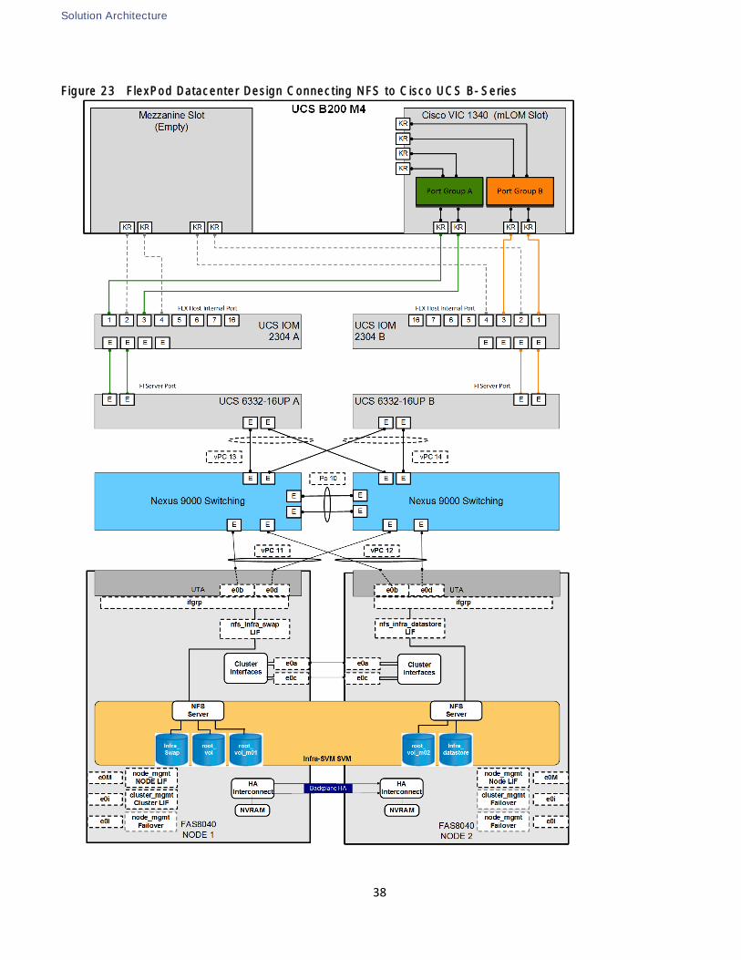
Solution Architecture
38
Figure 23 FlexPod Datacenter Design Connecting NFS to Cisco UCS B-Series
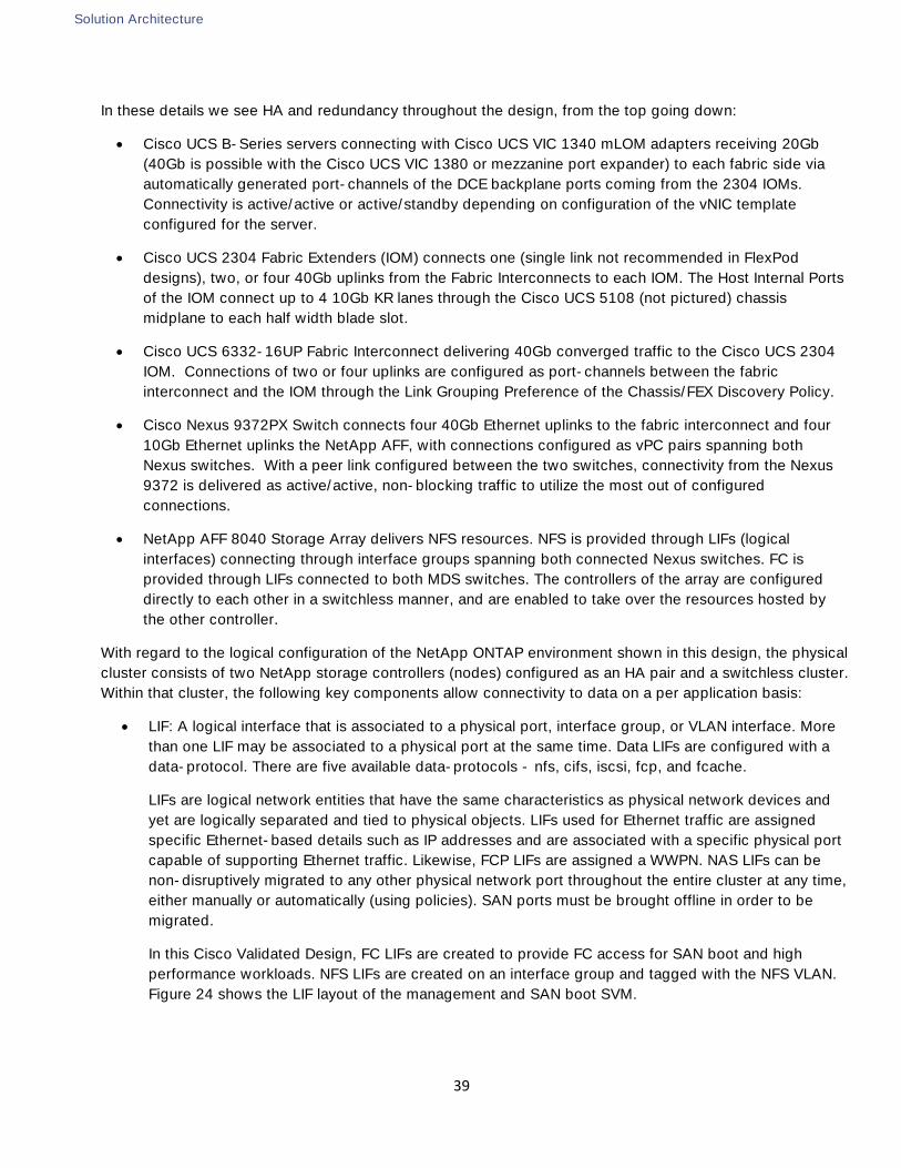
Solution Architecture
39
In these details we see HA and redundancy throughout the design, from the top going down:
Cisco UCS B-Series servers connecting with Cisco UCS VIC 1340 mLOM adapters receiving 20Gb
(40Gb is possible with the Cisco UCS VIC 1380 or mezzanine port expander) to each fabric side via
automatically generated port-channels of the DCE backplane ports coming from the 2304 IOMs.
Connectivity is active/active or active/standby depending on configuration of the vNIC template
configured for the server.
Cisco UCS 2304 Fabric Extenders (IOM) connects one (single link not recommended in FlexPod
designs), two, or four 40Gb uplinks from the Fabric Interconnects to each IOM. The Host Internal Ports
of the IOM connect up to 4 10Gb KR lanes through the Cisco UCS 5108 (not pictured) chassis
midplane to each half width blade slot.
Cisco UCS 6332-16UP Fabric Interconnect delivering 40Gb converged traffic to the Cisco UCS 2304
IOM. Connections of two or four uplinks are configured as port-channels between the fabric
interconnect and the IOM through the Link Grouping Preference of the Chassis/FEX Discovery Policy.
Cisco Nexus 9372PX Switch connects four 40Gb Ethernet uplinks to the fabric interconnect and four
10Gb Ethernet uplinks the NetApp AFF, with connections configured as vPC pairs spanning both
Nexus switches. With a peer link configured between the two switches, connectivity from the Nexus
9372 is delivered as active/active, non-blocking traffic to utilize the most out of configured
connections.
NetApp AFF 8040 Storage Array delivers NFS resources. NFS is provided through LIFs (logical
interfaces) connecting through interface groups spanning both connected Nexus switches. FC is
provided through LIFs connected to both MDS switches. The controllers of the array are configured
directly to each other in a switchless manner, and are enabled to take over the resources hosted by
the other controller.
With regard to the logical configuration of the NetApp ONTAP environment shown in this design, the physical
cluster consists of two NetApp storage controllers (nodes) configured as an HA pair and a switchless cluster.
Within that cluster, the following key components allow connectivity to data on a per application basis:
LIF: A logical interface that is associated to a physical port, interface group, or VLAN interface. More
than one LIF may be associated to a physical port at the same time. Data LIFs are configured with a
data-protocol. There are five available data-protocols - nfs, cifs, iscsi, fcp, and fcache.
LIFs are logical network entities that have the same characteristics as physical network devices and
yet are logically separated and tied to physical objects. LIFs used for Ethernet traffic are assigned
specific Ethernet-based details such as IP addresses and are associated with a specific physical port
capable of supporting Ethernet traffic. Likewise, FCP LIFs are assigned a WWPN. NAS LIFs can be
non-disruptively migrated to any other physical network port throughout the entire cluster at any time,
either manually or automatically (using policies). SAN ports must be brought offline in order to be
migrated.
In this Cisco Validated Design, FC LIFs are created to provide FC access for SAN boot and high
performance workloads. NFS LIFs are created on an interface group and tagged with the NFS VLAN.
Figure 24 shows the LIF layout of the management and SAN boot SVM.
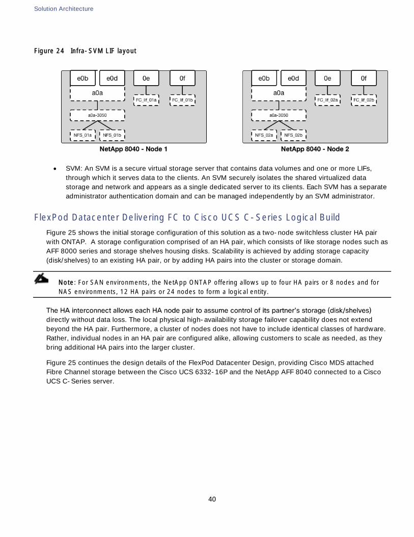
Solution Architecture
40
Figure 24 Infra-SVM LIF layout
SVM: An SVM is a secure virtual storage server that contains data volumes and one or more LIFs,
through which it serves data to the clients. An SVM securely isolates the shared virtualized data
storage and network and appears as a single dedicated server to its clients. Each SVM has a separate
administrator authentication domain and can be managed independently by an SVM administrator.
FlexPod Datacenter Delivering FC to Cisco UCS C-Series Logical Build
Figure 25 shows the initial storage configuration of this solution as a two-node switchless cluster HA pair
with ONTAP. A storage configuration comprised of an HA pair, which consists of like storage nodes such as
AFF 8000 series and storage shelves housing disks. Scalability is achieved by adding storage capacity
(disk/shelves) to an existing HA pair, or by adding HA pairs into the cluster or storage domain.
Note: For SAN environments, the NetApp ONTAP offering allows up to four HA pairs or 8 nodes and for
NAS environments, 12 HA pairs or 24 nodes to form a logical entity.
directly without data loss. The local physical high-availability storage failover capability does not extend
beyond the HA pair. Furthermore, a cluster of nodes does not have to include identical classes of hardware.
Rather, individual nodes in an HA pair are configured alike, allowing customers to scale as needed, as they
bring additional HA pairs into the larger cluster.
Figure 25 continues the design details of the FlexPod Datacenter Design, providing Cisco MDS attached
Fibre Channel storage between the Cisco UCS 6332-16P and the NetApp AFF 8040 connected to a Cisco
UCS C-Series server.
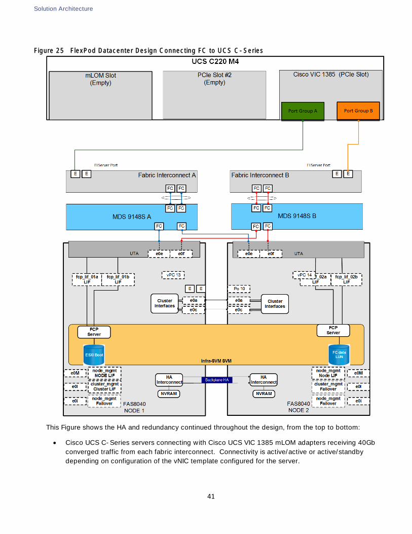
Solution Architecture
41
Figure 25 FlexPod Datacenter Design Connecting FC to UCS C-Series
This Figure shows the HA and redundancy continued throughout the design, from the top to bottom:
Cisco UCS C-Series servers connecting with Cisco UCS VIC 1385 mLOM adapters receiving 40Gb
converged traffic from each fabric interconnect. Connectivity is active/active or active/standby
depending on configuration of the vNIC template configured for the server.
Solution Architecture
42
Cisco UCS B-Series (not shown) with connection through the Cisco UCS 2304 IOM (not shown) will
receive the same connectivity as the Cisco UCS C-Series for the attached storage.
Cisco UCS 6332-16UP Fabric Interconnect connects and manages the Cisco UCS C-Series via single
wire management. Unified ports on the fabric interconnect are configured as 16Gb Storage FC
interfaces and attached to the MDS 9148Ss via SAN port channels. Storage 16 Gbps FC interfaces
are then connected to the MDS switches. NFS and potential iSCSI traffic is still handled by
connections to the Cisco Nexus 9372(not pictured) previously shown in 0.
Cisco MDS 9148S Switches create two redundant Fibre Channel SAN fabrics dedicated for storage
traffic. Dual 16Gb connections to each NetApp storage controller provide additional resiliency for host
multipathing. Port-channels connect each fabric to a Fabric Interconnects aggregating the Fibre
Channel links and providing 32Gb of bandwidth to the Fabric Interconnect.
NetApp AFF 8040 Storage Array delivers Fibre Channel resources through LIFs that connect to each
MDS switch via 16GB FC configured unified target adapters. The controllers of the array are
configured directly to each other in a switchless manner, and are enabled to take over the resources
hosted by the other controller.
The comparable configuration for the Cisco UCS FI 6248UP will use the same ports, but will differ with the
Cisco UCS C-Series using a VIC 1227 mLOM adapter at 10Gb converged instead of the VIC 1385 shown,
and the MDS to fabric interconnect connections occurring as 8Gb FC.
Cisco Unified Computing System Design
The FlexPod Datacenter design supports both Cisco UCS B-Series and C-Series deployments connecting to
either 6300 or 6200 series fabric interconnects. This section of the document discusses the integration of
each deployment into FlexPod. The Cisco Unified Computing System supports the virtual server environment
by providing a robust, highly available, and extremely manageable compute resource. The components of
the Cisco UCS system offer physical redundancy and a set of logical structures to deliver a very resilient
FlexPod compute domain. In this validation effort, there was a mixture of multiple Cisco UCS B-Series and
Cisco UCS C-Series ESXi servers that are booted from SAN using fibre channel. The Cisco UCS B200-M4
series blades were equipped with Cisco 1340 VIC adapters and the Cisco UCS C220-M4 used a Cisco 1385
or 1387 VIC or Cisco 1227 VIC. These nodes were allocated to a VMware DRS and HA enabled cluster
supporting infrastructure services such as vSphere Virtual Center, Microsoft Active Directory and database
services.
Cisco UCS vNIC Resiliency
The FlexPod defines vNICs that can trace their connectivity back to the two LAN port channels connecting
the Cisco UCS Fabric Interconnects to the Cisco Nexus 9000. NFS traffic from the servers use these two
port-channels to communicate to the storage system. At the server level, the Cisco 1340 VIC presents six
virtual PCIe devices to the ESXi node, two virtual 20 Gb Ethernet NICs (vNIC) for infrastructure, two 20 Gb
vNICs for vMotion, and two 20 Gb vNICs for the distributed virtual switch (DVS) (Figure 26Error! Reference
source not found.). These vNICs will be 40Gb with a Cisco UCS C-Series and 1385 or 1387 VIC
connecting to the fabric interconnect, and can be 40Gb with a B-Series provided it is equipped with a
mezzanine port expander. The vSphere environment identifies these interfaces as vmnics and the ESXi
operating system is unaware these are virtual adapters. The result is a dual-homed ESXi node to the
remaining network. Note that when the VMware vDS is used, In Band Management and the Infrastructure
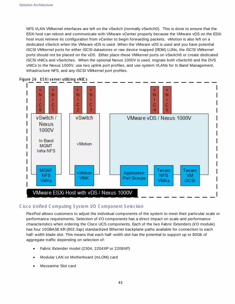
Solution Architecture
43
NFS VLAN VMkernel interfaces are left on the vSwitch (normally vSwitch0). This is done to ensure that the
ESXi host can reboot and communicate with VMware vCenter properly because the VMware vDS on the ESXi
host must retrieve its configuration from vCenter to begin forwarding packets. vMotion is also left on a
dedicated vSwitch when the VMware vDS is used. When the VMware vDS is used and you have potential
iSCSI VMkernel ports for either iSCSI datastores or raw device mapped (RDM) LUNs, the iSCSI VMkernel
ports should not be placed on the vDS. Either place these VMkernel ports on vSwitch0 or create dedicated
iSCSI vNICs and vSwitches. When the optional Nexus 1000V is used, migrate both vSwitch0 and the DVS
vNICs to the Nexus 1000V, use two uplink port profiles, and use system VLANs for In Band Management,
Infrastructure NFS, and any iSCSI VMkernel port profiles.
Figure 26 ESXi server utilizing vNICs
Cisco Unified Computing System I/O Component Selection
FlexPod allows customers to adjust the individual components of the system to meet their particular scale or
performance requirements. Selection of I/O components has a direct impact on scale and performance
characteristics when ordering the Cisco UCS components. Each of the two Fabric Extenders (I/O module)
has four 10GBASE KR (802.3ap) standardized Ethernet backplane paths available for connection to each
half-width blade slot. This means that each half-width slot has the potential to support up to 80Gb of
aggregate traffic depending on selection of:
Fabric Extender model (2304, 2204XP or 2208XP)
Modular LAN on Motherboard (mLOM) card
Mezzanine Slot card
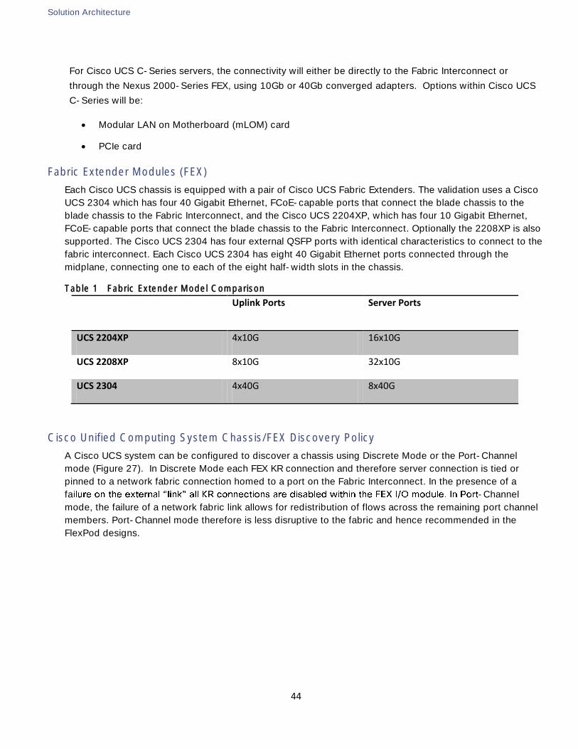
Solution Architecture
44
For Cisco UCS C-Series servers, the connectivity will either be directly to the Fabric Interconnect or
through the Nexus 2000-Series FEX, using 10Gb or 40Gb converged adapters. Options within Cisco UCS
C-Series will be:
Modular LAN on Motherboard (mLOM) card
PCIe card
Fabric Extender Modules (FEX)
Each Cisco UCS chassis is equipped with a pair of Cisco UCS Fabric Extenders. The validation uses a Cisco
UCS 2304 which has four 40 Gigabit Ethernet, FCoE-capable ports that connect the blade chassis to the
blade chassis to the Fabric Interconnect, and the Cisco UCS 2204XP, which has four 10 Gigabit Ethernet,
FCoE-capable ports that connect the blade chassis to the Fabric Interconnect. Optionally the 2208XP is also
supported. The Cisco UCS 2304 has four external QSFP ports with identical characteristics to connect to the
fabric interconnect. Each Cisco UCS 2304 has eight 40 Gigabit Ethernet ports connected through the
midplane, connecting one to each of the eight half-width slots in the chassis.
Table 1 Fabric Extender Model Comparison
Uplink Ports Server Ports
UCS 2204XP 4x10G 16x10G
UCS 2208XP 8x10G 32x10G
UCS 2304 4x40G 8x40G
Cisco Unified Computing System Chassis/FEX Discovery Policy
A Cisco UCS system can be configured to discover a chassis using Discrete Mode or the Port-Channel
mode (Figure 27). In Discrete Mode each FEX KR connection and therefore server connection is tied or
pinned to a network fabric connection homed to a port on the Fabric Interconnect. In the presence of a
fa -Channel
mode, the failure of a network fabric link allows for redistribution of flows across the remaining port channel
members. Port-Channel mode therefore is less disruptive to the fabric and hence recommended in the
FlexPod designs.
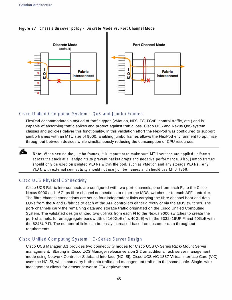
Solution Architecture
45
Figure 27 Chassis discover policy - Discrete Mode vs. Port Channel Mode
Cisco Unified Computing System QoS and Jumbo Frames
FlexPod accommodates a myriad of traffic types (vMotion, NFS, FC, FCoE, control traffic, etc.) and is
capable of absorbing traffic spikes and protect against traffic loss. Cisco UCS and Nexus QoS system
classes and policies deliver this functionality. In this validation effort the FlexPod was configured to support
jumbo frames with an MTU size of 9000. Enabling jumbo frames allows the FlexPod environment to optimize
throughput between devices while simultaneously reducing the consumption of CPU resources.
Note: When setting the Jumbo frames, it is important to make sure MTU settings are applied uniformly
across the stack at all endpoints to prevent packet drops and negative performance. Also, Jumbo frames
should only be used on isolated VLANs within the pod, such as vMotion and any storage VLANs. Any
VLAN with external connectivity should not use Jumbo frames and should use MTU 1500.
Cisco UCS Physical Connectivity
Cisco UCS Fabric Interconnects are configured with two port-channels, one from each FI, to the Cisco
Nexus 9000 and 16Gbps fibre channel connections to either the MDS switches or to each AFF controller.
The fibre channel connections are set as four independent links carrying the fibre channel boot and data
LUNs from the A and B fabrics to each of the AFF controllers either directly or via the MDS switches. The
port-channels carry the remaining data and storage traffic originated on the Cisco Unified Computing
System. The validated design utilized two uplinks from each FI to the Nexus 9000 switches to create the
port-channels, for an aggregate bandwidth of 160GbE (4 x 40GbE) with the 6332-16UP FI and 40GbE with
the 6248UP FI. The number of links can be easily increased based on customer data throughput
requirements.
Cisco Unified Computing System C-Series Server Design
Cisco UCS Manager 3.1 provides two connectivity modes for Cisco UCS C-Series Rack-Mount Server
management. Starting in Cisco UCS Manager release version 2.2 an additional rack server management
mode using Network Controller Sideband Interface (NC-SI). Cisco UCS VIC 1387 Virtual Interface Card (VIC)
uses the NC-SI, which can carry both data traffic and management traffic on the same cable. Single-wire
management allows for denser server to FEX deployments.
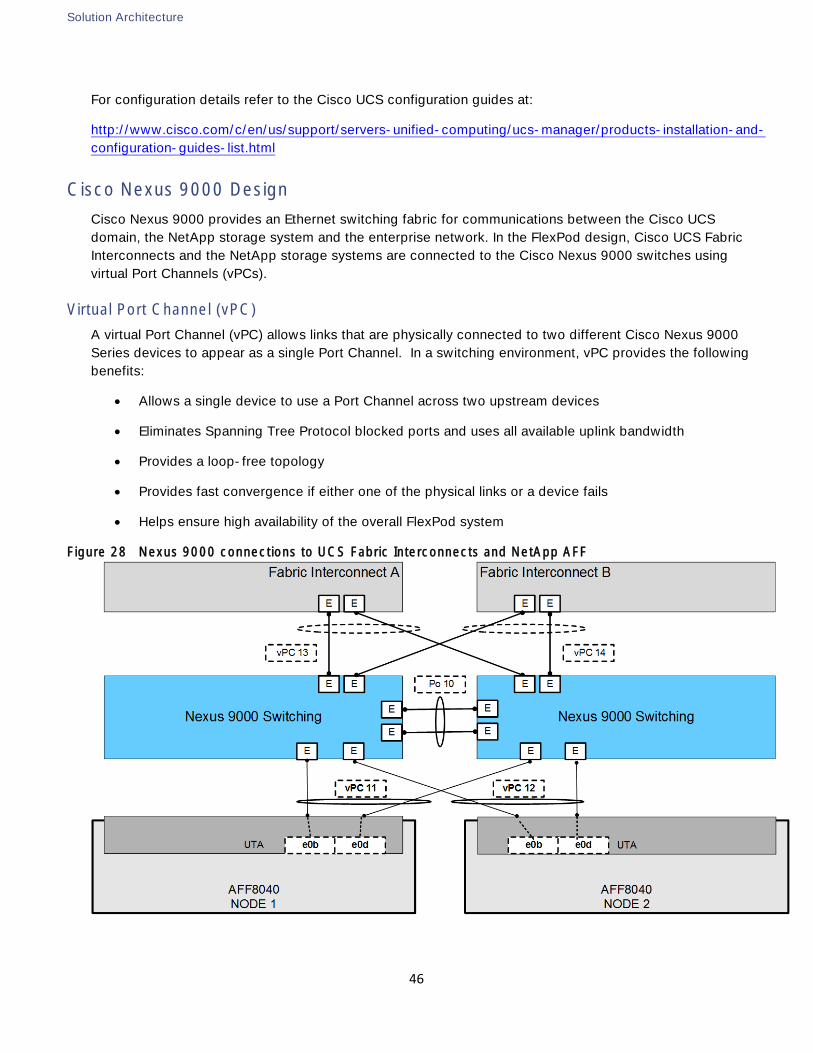
Solution Architecture
46
For configuration details refer to the Cisco UCS configuration guides at:
http://www.cisco.com/c/en/us/support/servers-unified-computing/ucs-manager/products-installation-and-
configuration-guides-list.html
Cisco Nexus 9000 Design
Cisco Nexus 9000 provides an Ethernet switching fabric for communications between the Cisco UCS
domain, the NetApp storage system and the enterprise network. In the FlexPod design, Cisco UCS Fabric
Interconnects and the NetApp storage systems are connected to the Cisco Nexus 9000 switches using
virtual Port Channels (vPCs).
Virtual Port Channel (vPC)
A virtual Port Channel (vPC) allows links that are physically connected to two different Cisco Nexus 9000
Series devices to appear as a single Port Channel. In a switching environment, vPC provides the following
benefits:
Allows a single device to use a Port Channel across two upstream devices
Eliminates Spanning Tree Protocol blocked ports and uses all available uplink bandwidth
Provides a loop-free topology
Provides fast convergence if either one of the physical links or a device fails
Helps ensure high availability of the overall FlexPod system
Figure 28 Nexus 9000 connections to UCS Fabric Interconnects and NetApp AFF
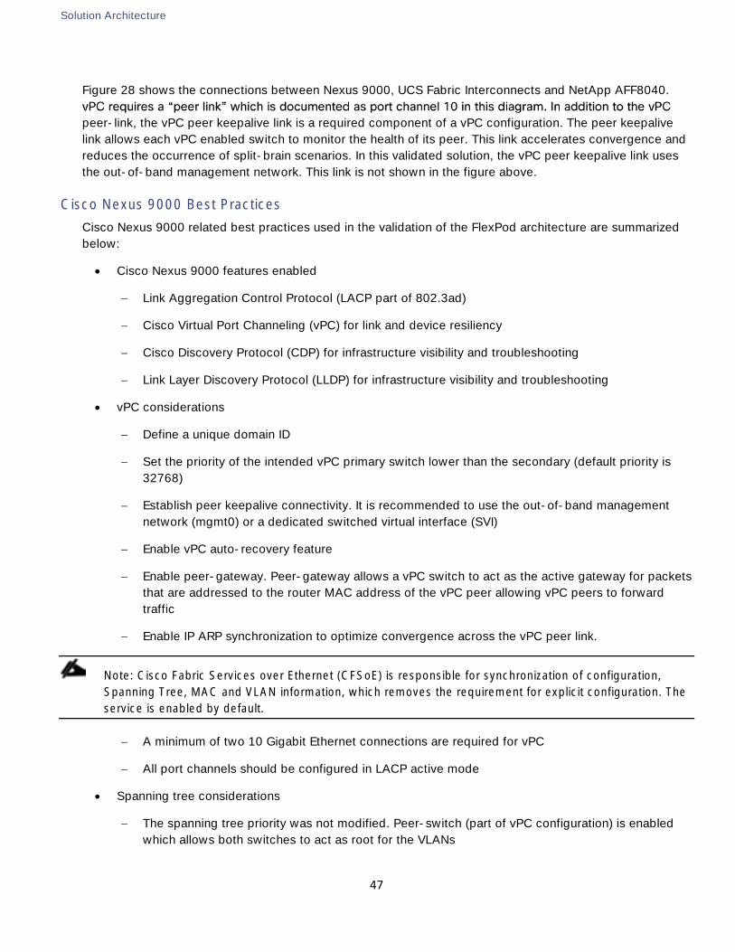
Solution Architecture
47
Figure 28 shows the connections between Nexus 9000, UCS Fabric Interconnects and NetApp AFF8040.
peer-link, the vPC peer keepalive link is a required component of a vPC configuration. The peer keepalive
link allows each vPC enabled switch to monitor the health of its peer. This link accelerates convergence and
reduces the occurrence of split-brain scenarios. In this validated solution, the vPC peer keepalive link uses
the out-of-band management network. This link is not shown in the figure above.
Cisco Nexus 9000 Best Practices
Cisco Nexus 9000 related best practices used in the validation of the FlexPod architecture are summarized
below:
Cisco Nexus 9000 features enabled
Link Aggregation Control Protocol (LACP part of 802.3ad)
Cisco Virtual Port Channeling (vPC) for link and device resiliency
Cisco Discovery Protocol (CDP) for infrastructure visibility and troubleshooting
Link Layer Discovery Protocol (LLDP) for infrastructure visibility and troubleshooting
vPC considerations
Define a unique domain ID
Set the priority of the intended vPC primary switch lower than the secondary (default priority is
32768)
Establish peer keepalive connectivity. It is recommended to use the out-of-band management
network (mgmt0) or a dedicated switched virtual interface (SVI)
Enable vPC auto-recovery feature
Enable peer-gateway. Peer-gateway allows a vPC switch to act as the active gateway for packets
that are addressed to the router MAC address of the vPC peer allowing vPC peers to forward
traffic
Enable IP ARP synchronization to optimize convergence across the vPC peer link.
Note: Cisco Fabric Services over Ethernet (CFSoE) is responsible for synchronization of configuration,
Spanning Tree, MAC and VLAN information, which removes the requirement for explicit configuration. The
service is enabled by default.
A minimum of two 10 Gigabit Ethernet connections are required for vPC
All port channels should be configured in LACP active mode
Spanning tree considerations
The spanning tree priority was not modified. Peer-switch (part of vPC configuration) is enabled
which allows both switches to act as root for the VLANs
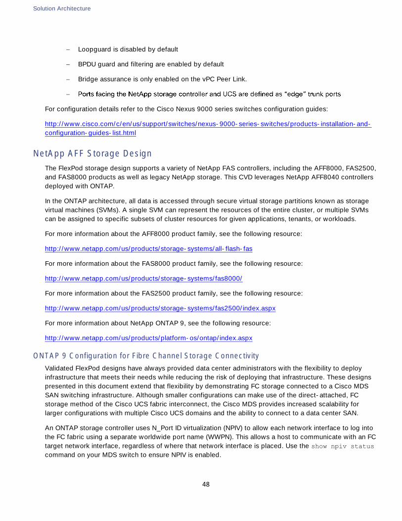
Solution Architecture
48
Loopguard is disabled by default
BPDU guard and filtering are enabled by default
Bridge assurance is only enabled on the vPC Peer Link.
For configuration details refer to the Cisco Nexus 9000 series switches configuration guides:
http://www.cisco.com/c/en/us/support/switches/nexus-9000-series-switches/products-installation-and-
configuration-guides-list.html
NetApp AFF Storage Design
The FlexPod storage design supports a variety of NetApp FAS controllers, including the AFF8000, FAS2500,
and FAS8000 products as well as legacy NetApp storage. This CVD leverages NetApp AFF8040 controllers
deployed with ONTAP.
In the ONTAP architecture, all data is accessed through secure virtual storage partitions known as storage
virtual machines (SVMs). A single SVM can represent the resources of the entire cluster, or multiple SVMs
can be assigned to specific subsets of cluster resources for given applications, tenants, or workloads.
For more information about the AFF8000 product family, see the following resource:
http://www.netapp.com/us/products/storage-systems/all-flash-fas
For more information about the FAS8000 product family, see the following resource:
http://www.netapp.com/us/products/storage-systems/fas8000/
For more information about the FAS2500 product family, see the following resource:
http://www.netapp.com/us/products/storage-systems/fas2500/index.aspx
For more information about NetApp ONTAP 9, see the following resource:
http://www.netapp.com/us/products/platform-os/ontap/index.aspx
ONTAP 9 Configuration for Fibre Channel Storage Connectivity
Validated FlexPod designs have always provided data center administrators with the flexibility to deploy
infrastructure that meets their needs while reducing the risk of deploying that infrastructure. These designs
presented in this document extend that flexibility by demonstrating FC storage connected to a Cisco MDS
SAN switching infrastructure. Although smaller configurations can make use of the direct-attached, FC
storage method of the Cisco UCS fabric interconnect, the Cisco MDS provides increased scalability for
larger configurations with multiple Cisco UCS domains and the ability to connect to a data center SAN.
An ONTAP storage controller uses N_Port ID virtualization (NPIV) to allow each network interface to log into
the FC fabric using a separate worldwide port name (WWPN). This allows a host to communicate with an FC
target network interface, regardless of where that network interface is placed. Use the show npiv status
command on your MDS switch to ensure NPIV is enabled.
Solution Architecture
49
The NetApp AFF8040 storage controller is equipped with two FC targets per controller. The number of ports
used on the NetApp storage controller can be modified depending on your specific requirements. Each
storage controller is connected to two SAN fabrics. This method provides increased redundancy to make
sure that paths from the host to its storage LUNs are always available. Figure 29 shows the connection
diagram for the AFF storage to the MDS SAN fabrics. This FlexPod design uses the following port and
interface assignments:
Figure 29 Storage controller connections to SAN fabrics
Onboard CNA port 0e in FC target mode connected to SAN fabric A. FCP logical network interfaces
(LIFs) are created on this port in each SVM enabled for FC.
Onboard CNA port 0f in FC target mode connected to SAN fabric B. FCP LIFs are created on this
port in each SVM enabled for FC.
Unlike NAS network interfaces, the SAN network interfaces are not configured to failover during HA failover.
Instead if a network interface becomes unavailable, the host chooses a new optimized path to an available
network interface. ALUA is a standard supported by NetApp used to provide information about SCSI targets
which allows a host to identify the best path to the storage.
Network and Storage Physical Connectivity
This design demonstrates FC for SAN boot and specific workloads. Ethernet networking is also configured
for general purpose NFS workloads and performance comparisons between protocols. NetApp AFF8000
storage controllers are configured with two port channels connected to the Cisco Nexus 9000 switches.
These port channels carry all IP-based data traffic for the NetApp controllers. This validated design uses two
physical ports from each NetApp controller configured as an LACP interface group. The number of ports
used can be easily modified depending on the application requirements.
An ONTAP storage solution includes the following fundamental connections or network types:
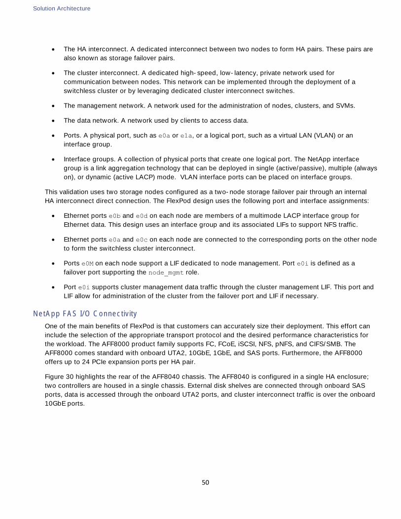
Solution Architecture
50
The HA interconnect. A dedicated interconnect between two nodes to form HA pairs. These pairs are
also known as storage failover pairs.
The cluster interconnect. A dedicated high-speed, low-latency, private network used for
communication between nodes. This network can be implemented through the deployment of a
switchless cluster or by leveraging dedicated cluster interconnect switches.
The management network. A network used for the administration of nodes, clusters, and SVMs.
The data network. A network used by clients to access data.
Ports. A physical port, such as e0a or e1a, or a logical port, such as a virtual LAN (VLAN) or an
interface group.
Interface groups. A collection of physical ports that create one logical port. The NetApp interface
group is a link aggregation technology that can be deployed in single (active/passive), multiple (always
on), or dynamic (active LACP) mode. VLAN interface ports can be placed on interface groups.
This validation uses two storage nodes configured as a two-node storage failover pair through an internal
HA interconnect direct connection. The FlexPod design uses the following port and interface assignments:
Ethernet ports e0b and e0d on each node are members of a multimode LACP interface group for
Ethernet data. This design uses an interface group and its associated LIFs to support NFS traffic.
Ethernet ports e0a and e0c on each node are connected to the corresponding ports on the other node
to form the switchless cluster interconnect.
Ports e0M on each node support a LIF dedicated to node management. Port e0i is defined as a
failover port supporting the node_mgmt role.
Port e0i supports cluster management data traffic through the cluster management LIF. This port and
LIF allow for administration of the cluster from the failover port and LIF if necessary.
NetApp FAS I/O Connectivity
One of the main benefits of FlexPod is that customers can accurately size their deployment. This effort can
include the selection of the appropriate transport protocol and the desired performance characteristics for
the workload. The AFF8000 product family supports FC, FCoE, iSCSI, NFS, pNFS, and CIFS/SMB. The
AFF8000 comes standard with onboard UTA2, 10GbE, 1GbE, and SAS ports. Furthermore, the AFF8000
offers up to 24 PCIe expansion ports per HA pair.
Figure 30 highlights the rear of the AFF8040 chassis. The AFF8040 is configured in a single HA enclosure;
two controllers are housed in a single chassis. External disk shelves are connected through onboard SAS
ports, data is accessed through the onboard UTA2 ports, and cluster interconnect traffic is over the onboard
10GbE ports.
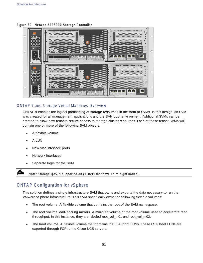
Solution Architecture
51
Figure 30 NetApp AFF8000 Storage Controller
ONTAP 9 and Storage Virtual Machines Overview
ONTAP 9 enables the logical partitioning of storage resources in the form of SVMs. In this design, an SVM
was created for all management applications and the SAN boot environment. Additional SVMs can be
created to allow new tenants secure access to storage cluster resources. Each of these tenant SVMs will
contain one or more of the following SVM objects:
A flexible volume
A LUN
New vlan interface ports
Network interfaces
Separate login for the SVM
Note: Storage QoS is supported on clusters that have up to eight nodes.
ONTAP Configuration for vSphere
This solution defines a single infrastructure SVM that owns and exports the data necessary to run the
VMware vSphere infrastructure. This SVM specifically owns the following flexible volumes:
The root volume. A flexible volume that contains the root of the SVM namespace.
The root volume load-sharing mirrors. A mirrored volume of the root volume used to accelerate read
throughput. In this instance, they are labeled root_vol_m01 and root_vol_m02.
The boot volume. A flexible volume that contains the ESXi boot LUNs. These ESXi boot LUNs are
exported through FCP to the Cisco UCS servers.
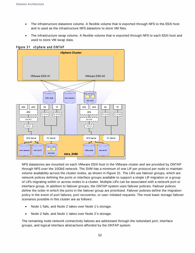
Solution Architecture
52
The infrastructure datastore volume. A flexible volume that is exported through NFS to the ESXi host
and is used as the infrastructure NFS datastore to store VM files.
The infrastructure swap volume. A flexible volume that is exported through NFS to each ESXi host and
used to store VM swap data.
Figure 31 vSphere and ONTAP
NFS datastores are mounted on each VMware ESXi host in the VMware cluster and are provided by ONTAP
through NFS over the 10GbE network. The SVM has a minimum of one LIF per protocol per node to maintain
volume availability across the cluster nodes, as shown in Figure 31. The LIFs use failover groups, which are
network polices defining the ports or interface groups available to support a single LIF migration or a group
of LIFs migrating within or across nodes in a cluster. Multiple LIFs can be associated with a network port or
interface group. In addition to failover groups, the ONTAP system uses failover policies. Failover polices
define the order in which the ports in the failover group are prioritized. Failover policies define the migration
policy in the event of port failures, port recoveries, or user-initiated requests. The most basic storage failover
scenarios possible in this cluster are as follows:
Node 1 fails, and Node 2 takes over Node 1's storage.
Node 2 fails, and Node 1 takes over Node 2's storage.
The remaining node network connectivity failures are addressed through the redundant port, interface
groups, and logical interface abstractions afforded by the ONTAP system.
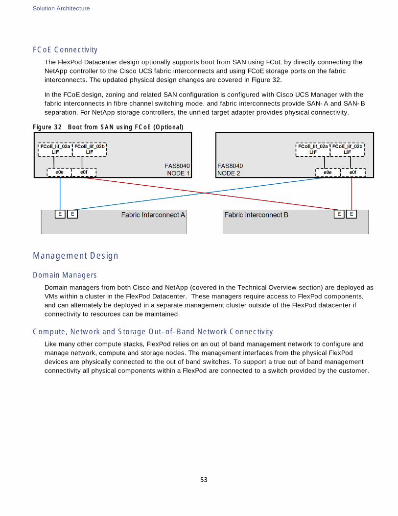
Solution Architecture
53
FCoE Connectivity
The FlexPod Datacenter design optionally supports boot from SAN using FCoE by directly connecting the
NetApp controller to the Cisco UCS fabric interconnects and using FCoE storage ports on the fabric
interconnects. The updated physical design changes are covered in Figure 32.
In the FCoE design, zoning and related SAN configuration is configured with Cisco UCS Manager with the
fabric interconnects in fibre channel switching mode, and fabric interconnects provide SAN-A and SAN-B
separation. For NetApp storage controllers, the unified target adapter provides physical connectivity.
Figure 32 Boot from SAN using FCoE (Optional)
Management Design
Domain Managers
Domain managers from both Cisco and NetApp (covered in the Technical Overview section) are deployed as
VMs within a cluster in the FlexPod Datacenter. These managers require access to FlexPod components,
and can alternately be deployed in a separate management cluster outside of the FlexPod datacenter if
connectivity to resources can be maintained.
Compute, Network and Storage Out-of-Band Network Connectivity
Like many other compute stacks, FlexPod relies on an out of band management network to configure and
manage network, compute and storage nodes. The management interfaces from the physical FlexPod
devices are physically connected to the out of band switches. To support a true out of band management
connectivity all physical components within a FlexPod are connected to a switch provided by the customer.
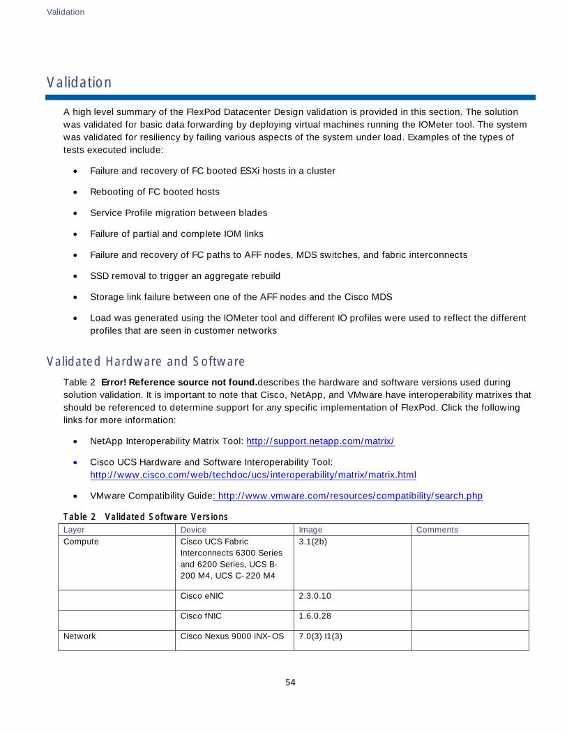
Validation
54
Validation
A high level summary of the FlexPod Datacenter Design validation is provided in this section. The solution
was validated for basic data forwarding by deploying virtual machines running the IOMeter tool. The system
was validated for resiliency by failing various aspects of the system under load. Examples of the types of
tests executed include:
Failure and recovery of FC booted ESXi hosts in a cluster
Rebooting of FC booted hosts
Service Profile migration between blades
Failure of partial and complete IOM links
Failure and recovery of FC paths to AFF nodes, MDS switches, and fabric interconnects
SSD removal to trigger an aggregate rebuild
Storage link failure between one of the AFF nodes and the Cisco MDS
Load was generated using the IOMeter tool and different IO profiles were used to reflect the different
profiles that are seen in customer networks
Validated Hardware and Software
Table 2 Error! Reference source not found.describes the hardware and software versions used during
solution validation. It is important to note that Cisco, NetApp, and VMware have interoperability matrixes that
should be referenced to determine support for any specific implementation of FlexPod. Click the following
links for more information:
NetApp Interoperability Matrix Tool: http://support.netapp.com/matrix/
Cisco UCS Hardware and Software Interoperability Tool:
http://www.cisco.com/web/techdoc/ucs/interoperability/matrix/matrix.html
VMware Compatibility Guide: http://www.vmware.com/resources/compatibility/search.php
Table 2 Validated Software Versions
Layer Device Image Comments
Compute Cisco UCS Fabric
Interconnects 6300 Series
and 6200 Series, UCS B-
200 M4, UCS C-220 M4
3.1(2b)
Cisco eNIC 2.3.0.10
Cisco fNIC 1.6.0.28
Network Cisco Nexus 9000 iNX-OS 7.0(3) I1(3)
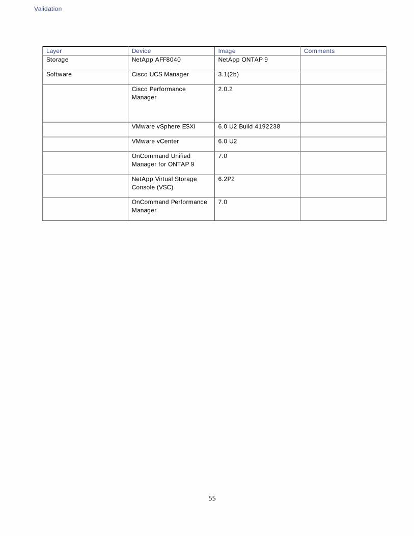
Validation
55
Layer Device Image Comments
Storage NetApp AFF8040 NetApp ONTAP 9
Software Cisco UCS Manager 3.1(2b)
Cisco Performance
Manager
2.0.2
VMware vSphere ESXi 6.0 U2 Build 4192238
VMware vCenter 6.0 U2
OnCommand Unified
Manager for ONTAP 9 7.0
NetApp Virtual Storage
Console (VSC) 6.2P2
OnCommand Performance
Manager 7.0
Summary
56
Summary
FlexPod Datacenter with VMware vSphere 6.0 and Fibre Channel is the optimal shared infrastructure
foundation to deploy a variety of IT workloads that is future proofed with 16 Gb/s FC and 40Gb Ethernet
connectivity. Cisco and NetApp have created a platform that is both flexible and scalable for multiple use
cases and applications. From virtual desktop infrastructure to SAP®, FlexPod can efficiently and effectively
support business-critical applications running simultaneously from the same shared infrastructure. The
flexibility and scalability of FlexPod also enable customers to start out with a right-sized infrastructure that
can ultimately grow with and adapt to their evolving business requirements.
References
57
References
Products and Solutions
Cisco Unified Computing System:
http://www.cisco.com/en/US/products/ps10265/index.html
Cisco UCS 6300 Series Fabric Interconnects:
http://www.cisco.com/c/en/us/products/servers-unified-computing/ucs-6300-series-fabric-
interconnects/index.html
Cisco UCS 5100 Series Blade Server Chassis:
http://www.cisco.com/en/US/products/ps10279/index.html
Cisco UCS B-Series Blade Servers:
http://www.cisco.com/en/US/partner/products/ps10280/index.html
Cisco UCS Adapters:
http://www.cisco.com/en/US/products/ps10277/prod_module_series_home.html
Cisco UCS Manager:
http://www.cisco.com/en/US/products/ps10281/index.html
Cisco Nexus 9000 Series Switches:
http://www.cisco.com/c/en/us/products/switches/nexus-9000-series-switches/index.html
Cisco MDS 9000 Multilayer Fabric Switches:
http://www.cisco.com/c/en/us/products/storage-networking/mds-9000-series-multilayer-
switches/index.html
VMware vCenter Server:
http://www.vmware.com/products/vcenter-server/overview.html
VMware vSphere:
https://www.vmware.com/products/vsphere
NetApp ONTAP 9:
http://www.netapp.com/us/products/platform-os/ontap/index.aspx
NetApp FAS8000:
http://www.netapp.com/us/products/storage-systems/fas8000/
References
58
NetApp OnCommand:
http://www.netapp.com/us/products/management-software/
NetApp VSC:
http://www.netapp.com/us/products/management-software/vsc/
NetApp SnapManager:
http://www.netapp.com/us/products/management-software/snapmanager/
Interoperability Matrixes
Cisco UCS Hardware Compatibility Matrix:
http://www.cisco.com/c/en/us/support/servers-unified-computing/unified-computing-system/products-
technical-reference-list.html
VMware and Cisco Unified Computing System:
http://www.vmware.com/resources/compatibility
NetApp Interoperability Matrix Tool:
http://support.netapp.com/matrix/
About the Authors
59
About the Authors
John George, Technical Marketing Engineer, Cisco UCS Data Center Solutions Engineering, Cisco
Systems, Inc.
John George recently moved to Cisco from Netapp and is focused on designing, developing, validating, and
supporting the FlexPod Converged Infrastructure. Before his roles with FlexPod, he supported and
administered a large worldwide training network and VPN infrastructure. John holds a Master's degree in
Computer Engineering from Clemson University.
Aaron Kirk, Technical Marketing Engineer, Infrastructure and Cloud Engineering, NetApp
Aaron Kirk is a Technical Marketing Engineer in the NetApp Infrastructure and Cloud Engineering team. He
focuses on producing validated reference architectures that promote the benefits of end-to-end datacenter
solutions and cloud environments. Aaron has been at NetApp since 2010, previously working as an engineer
on the MetroCluster product in the Data Protection Group. Aaron holds a Bachelor of Science in Computer
Science and a Masters of Business Administration from North Carolina State University.
Acknowledgements
For their support and contribution to the design, validation, and creation of this Cisco Validated Design, the
authors would like to thank:
Dave Klem, NetApp
Glenn Sizemore, NetApp
Ramesh Isaac, Cisco