Embed Size (px)
Citation preview

FlexPod Datacenter with VMware vSphere 5.5 Update 1 Design Guide
Last Updated: August 11, 2014
Building Architectures to Solve Business Problems

Cisco Validated Design2

About the Authors
ere 5. He has presented at various industry conferences.
Technical Marketing Manager, Server Access Virtualization Business Unit, Cisco
is currently focused on developing infrastructure best practices and solutions that are d, and documented to facilitate and improve customer deployments. Previously, O'Brien tion developer and has worked in the IT industry for more than 15 years.
akrishnan, Systems Architect, Infrastructure and Cloud Engineering, NetApp
akrishnan is a Systems Architect in the NetApp Infrastructure and Cloud Engineering es on the validating, supporting, implementing cloud infrastructure solutions that include cts. Prior to his current role, he was a networking tools developer at America Online L transit data network. Karthick started his career in 2003 and he holds Master's degree pplication.
rishnan, Technical Marketing Engineer, Infrastructure and Cloud Engineering, NetApp
rishnan is a Technical Marketing Engineer in the NetApp Infrastructure and Cloud am and is focused on developing, validating and supporting converged infrastructure nclude NetApp products. Before his current role, he was a Software Engineer at EMC lications for cloud infrastructure management.
l, Systems Architect, Infrastructure and Cloud Engineering, NetApp
ll designs, implements, and validates full-stack infrastructure solutions built using e. Craig has over five years of in-field experience designing and implementing l datacenter technologies and architectures. Craig's expertise includes datacenter and astructure architecture, datacenter administrator management and automation, VMware, iety of solutions built on enterprise datacenter architectures.
About the AuthorsJohn Kennedy, Technical Leader, Cisco
John Kennedy is a technical marketing engineer in the Server Access and Virtualization Technology group. Currently, John is focused on the validation of FlexPod architecture while contributing to future SAVTG products. John spent two years in the Systems Development unit at Cisco, researching methods of implementing long-distance vMotion for use in the Data Center Interconnect Cisco Validated Designs. Previously, John worked at VMware for eight and a half years as a senior systems engineer supporting channel partners outside the United States and serving on the HP Alliance team. He is a VMware Certified Professional on every version of VMware ESX and ESXi, vCenter, and Virtual Infrastructure, including vSph
Chris O'Brien,
Chris O'Brien designed, testewas an applica
Karthick Radh
Karthick Radhteam. He focusNetApp produsupporting AOin Computer A
Arvind Ramak
Arvind RamakEngineering tesolutions that ideveloping app
Craig Chadwel
Craig ChadweNetApp storagenterprise-leveconverged infrand a wide var
3

4About Cisco Validated Desig
About the Authors
n (CVD) Program
IM ALL WARRANTIES, INCLUDING, WITHOUT LIMITATION, THE WARRANTY OF
ILITY, FITNESS FOR A PARTICULAR PURPOSE AND NONINFRINGEMENT OR ARISING
SE OF DEALING, USAGE, OR TRADE PRACTICE. IN NO EVENT SHALL CISCO OR ITS
LIABLE FOR ANY INDIRECT, SPECIAL, CONSEQUENTIAL, OR INCIDENTAL DAMAGES,
ITHOUT LIMITATION, LOST PROFITS OR LOSS OR DAMAGE TO DATA ARISING OUT OF
ABILITY TO USE THE DESIGNS, EVEN IF CISCO OR ITS SUPPLIERS HAVE BEEN ADVISED
IBILITY OF SUCH DAMAGES.
ARE SUBJECT TO CHANGE WITHOUT NOTICE. USERS ARE SOLELY RESPONSIBLE FOR
TION OF THE DESIGNS. THE DESIGNS DO NOT CONSTITUTE THE TECHNICAL OR
SSIONAL ADVICE OF CISCO, ITS SUPPLIERS OR PARTNERS. USERS SHOULD CONSULT
CHNICAL ADVISORS BEFORE IMPLEMENTING THE DESIGNS. RESULTS MAY VARY
N FACTORS NOT TESTED BY CISCO.
Cisco Eos, Cisco Lumin, Cisco Nexus, Cisco StadiumVision, Cisco TelePresence, Cisco
co logo, DCE, and Welcome to the Human Network are trademarks; Changing the Way We
y, and Learn and Cisco Store are service marks; and Access Registrar, Aironet, AsyncOS,
eeting To You, Catalyst, CCDA, CCDP, CCIE, CCIP, CCNA, CCNP, CCSP, CCVP, Cisco, the
Internetwork Expert logo, Cisco IOS, Cisco Press, Cisco Systems, Cisco Systems Capital,
ems logo, Cisco Unity, Collaboration Without Limitation, EtherFast, EtherSwitch, Event Cen-
ollow Me Browsing, FormShare, GigaDrive, HomeLink, Internet Quotient, IOS, iPhone,
onPort, the IronPort logo, LightStream, Linksys, MediaTone, MeetingPlace, MeetingPlace
MGX, Networkers, Networking Academy, Network Registrar, PCNow, PIX, PowerPanels,
criptShare, SenderBase, SMARTnet, Spectrum Expert, StackWise, The Fastest Way to
nternet Quotient, TransPath, WebEx, and the WebEx logo are registered trademarks of
, Inc. and/or its affiliates in the United States and certain other countries.
arks mentioned in this document or website are the property of their respective owners.
word partner does not imply a partnership relationship between Cisco and any other com-
Systems, Inc. All rights reserved
About Cisco Validated Design (CVD) Program
The CVD program consists of systems and solutions designed, tested, and documented to facilitate
faster, more reliable, and more predictable customer deployments. For more information visit
http://www.cisco.com/go/designzone.
ALL DESIGNS, SPECIFICATIONS, STATEMENTS, INFORMATION, AND RECOMMENDATIONS (COLLEC-
TIVELY, "DESIGNS") IN THIS MANUAL ARE PRESENTED "AS IS," WITH ALL FAULTS. CISCO AND ITS SUP-
PLIERS DISCLA
MERCHANTAB
FROM A COUR
SUPPLIERS BE
INCLUDING, W
THE USE OR IN
OF THE POSS
THE DESIGNS
THEIR APPLICA
OTHER PROFE
THEIR OWN TE
DEPENDING O
CCDE, CCENT,
WebEx, the Cis
Work, Live, Pla
Bringing the M
Cisco Certified
the Cisco Syst
ter, Fast Step, F
iQuick Study, Ir
Chime Sound,
ProConnect, S
Increase Your I
Cisco Systems
All other tradem
The use of the
pany. (0809R)
© 2014 Cisco

FlexPod Datacenter with VMware vSphere 5.5 Update 1 Design Guide
About this DocumentCisco® Validated Designs include systems and solutions that are designed, tested, and documented to facilitate and improve customer deployments. These designs incorporate a wide range of technologies and products into a portfolio of solutions that have been developed to address the business needs of our customers.
This document describes the Cisco and NetApp® VMware vSphere 5.5 U1 on FlexPod® solution, which is a validated approach for deploying Cisco and NetApp technologies as a shared cloud infrastructure.
AudienceThe intended audience of this document includes, but is not limited to, sales engineers, field consultants, professional services, IT managers, partner engineering, and customers who want to take advantage of an infrastructure built to deliver IT efficiency and enable IT innovation.
IntroductionIndustry trends indicate a vast data center transformation toward shared infrastructure and cloud computing. Enterprise customers are moving away from silos of IT operation toward more cost-effective virtualized environments, leading eventually to cloud computing to increase agility and reduce costs. This transformation appears daunting and complex because companies must address resistance to change, in both their organizational and their technical IT models. To accelerate this process and simplify the evolution to a shared cloud infrastructure, Cisco and NetApp have developed a solution called VMware vSphere® on FlexPod.
FlexPod is a predesigned, best practice data center architecture that is built on the Cisco UCS, the Cisco Nexus® family of switches, and NetApp fabric-attached storage (FAS) or V-Series systems. FlexPod is a suitable platform for running a variety of virtualization hypervisors as well as bare metal operating systems and enterprise workloads. FlexPod delivers a baseline configuration and also has the flexibility to be sized and optimized to accommodate many different use cases and requirements.

Introduction
Figure 1 FlexPod Component Families
This document describes VMware vSphere 5.5 U1 built on the FlexPod model from Cisco and NetApp and discusses design choices and deployment of best practices using this shared infrastructure platform.
Changes in FlexPod
The following design elements distinguish this version of FlexPod from previous models:
• Cisco UCS C Series direct connection to Fabric Interconnects; Fabric Extenders, while still supported, are no longer necessary
• Support for the latest generation of Cisco UCS servers: M4
• Introducing NetApp FAS8000 series unified storage
• Support for VMware vSphere 5.5 Update 1
• Introduction of VMware Update Manager for patch management or vSphere ESXi servers.
• Introduction of VMware vSphere Web Client
• Server Firmware Auto Sync
• Implementation of Port Profiles in the Cisco Nexus upper layer switching for ease of management and configuration
• Cisco Nexus 1110-x 10Gb networking support
6FlexPod Datacenter with VMware vSphere 5.5 Update 1 Design Guide

Introduction
• Support for Cisco Nexus 5600 Series
Problem Statement
As customers transition toward shared infrastructure or cloud computing, they face a number of questions, such as:
• How do I start the transition?
• What will be my return on investment?
• How do I build a future-proof infrastructure?
• How do I cost-effectively transition from my current infrastructure?
• Will my applications run properly in a shared infrastructure?
• How do I manage the infrastructure?
The FlexPod architecture is designed to help with proven guidance and measurable value. By introducing standardization, FlexPod helps customers mitigate the risk and uncertainty involved in planning, designing, and implementing a new data center infrastructure. The result is a more predictive and adaptable architecture capable of meeting and exceeding customers' IT demands.
FlexPod Program Benefits
Cisco and NetApp have thoroughly validated and verified the FlexPod solution architecture and its many use cases while creating a portfolio of detailed documentation, information, and references to assist customers in transforming their data centers to this shared infrastructure model. This portfolio includes, but is not limited to the following items:
• Best practice architectural design
• Workload sizing and scaling guidance
• Implementation and deployment instructions
• Technical specifications (rules for what is, and what is not, a FlexPod configuration)
• Frequently asked questions (FAQs)
• Cisco Validated Designs (CVDs) and NetApp Validated Architectures (NVAs) focused on a variety of use cases
Cisco and NetApp have also built a robust and experienced support team focused on FlexPod solutions, from customer account and technical sales representatives to professional services and technical support engineers. The support alliance provided by NetApp and Cisco provides customers and channel services partners with direct access to technical experts who collaborate with cross vendors and have access to shared lab resources to resolve potential issues.
FlexPod supports tight integration with virtualized and cloud infrastructures, making it the logical choice for long-term investment. The following IT initiatives are addressed by the FlexPod solution.
7FlexPod Datacenter with VMware vSphere 5.5 Update 1 Design Guide

Introduction
Integrated System
FlexPod is a prevalidated infrastructure that brings together compute, storage, and network to simplify, accelerate, and minimize the risk associated with data center builds and application rollouts. These integrated systems provide a standardized approach in the data center that facilitates staff expertise, application onboarding, and automation as well as operational efficiencies relating to compliance and certification.
Fabric Infrastructure Resilience
FlexPod is a highly available and scalable infrastructure that IT can evolve over time to support multiple physical and virtual application workloads. FlexPod has no single point of failure at any level, from the server through the network, to the storage. The fabric is fully redundant and scalable and provides seamless traffic failover should any individual component fail at the physical or virtual layer.
Fabric Convergence
FlexPod components are interconnected through the Cisco Unified Fabric network architecture, which supports both traditional LAN traffic and all types of storage traffic, including the lossless requirements for block-level storage transport using Fibre Channel or FCoE. The Cisco Unified Fabric creates high-performance, low-latency, and highly available networks, serving a diverse set of data center needs.
FlexPod uses the Cisco Unified Fabric to offer a wire-once environment that accelerates application deployment, as well as offering efficiencies associated with infrastructure consolidation, including the following:
• Cost savings from the reduction in switches (LAN/SAN switch ports), associated cabling, rack space (capex), and associated power and cooling (opex)
• Migration to faster 10GbE network and to 40GbE and 100GbE in the future
• Evolution to a converged network with little disruption and preservation of investments in the existing infrastructure, management tools, and staff training (expertise)
• Simplified cabling, provisioning, and network maintenance to improve productivity and operational models
Network Virtualization
FlexPod delivers the capability to securely connect virtual machines into the network. This solution allows network policies and services to be uniformly applied within the integrated compute stack using technologies such as virtual LANs (VLANs), quality of service (QoS), and the Cisco Nexus 1000v virtual distributed switch. This capability enables the full utilization of FlexPod while maintaining consistent application and security policy enforcement across the stack even with workload mobility.
FlexPod provides a uniform approach to IT architecture, offering a well-characterized and documented shared pool of resources for application workloads. FlexPod delivers operational efficiency and consistency with the versatility to meet a variety of SLAs and IT initiatives, including:
• Application rollouts or application migrations
• Business continuity/disaster recovery
• Desktop virtualization
• Cloud delivery models (public, private, hybrid) and service models (IaaS, PaaS, SaaS)
• Asset consolidation and virtualization
8FlexPod Datacenter with VMware vSphere 5.5 Update 1 Design Guide

FlexPod
• Datacenter consolidation and footprint reduction
FlexPod
System Overview
FlexPod is a best practice datacenter architecture that includes three components:
• Cisco Unified Computing System (Cisco UCS)
• Cisco Nexus switches
• NetApp fabric-attached storage (FAS) systems
These components are connected and configured according to best practices of both Cisco and NetApp and provide the ideal platform for running a variety of enterprise workloads with confidence. FlexPod can scale up for greater performance and capacity (adding compute, network, or storage resources individually as needed), or it can scale out for environments that need multiple consistent deployments (rolling out additional FlexPod stacks). FlexPod delivers a baseline configuration and also has the flexibility to be sized and optimized to accommodate many different use cases.
Typically, the more scalable and flexible a solution is, the more difficult it becomes to maintain a single unified architecture capable of offering the same features and functionality across each implementation. This is one of the key benefits of FlexPod. Each of the component families shown in Figure 1 (Cisco UCS, Cisco Nexus, and NetApp FAS) offers platform and resource options to scale the infrastructure up or down, while supporting the same features and functionality that are required under the configuration and connectivity best practices of FlexPod.
Design Principles
FlexPod addresses four primary design principles: scalability, flexibility, availability, and manageability. These architecture goals are as follows:
• Application availability. Makes sure that services are accessible and ready to use.
• Scalability. Addresses increasing demands with appropriate resources.
• Flexibility. Provides new services or recovers resources without infrastructure modification requirements.
• Manageability. Facilitates efficient infrastructure operations through open standards and APIs.
Note Performance and comprehensive security are key design criteria that were not directly addressed in this project but have been addressed in other collateral, benchmarking, and solution testing efforts. Functionality and basic security elements are validated.
FlexPod: Distinct Uplink Design
Figure 2 details the FlexPod distinct uplink design with clustered Data ONTAP. As the illustrated, the design is fully redundant in the compute, network, and storage layers. There is no single point of failure from a device or traffic path perspective.
9FlexPod Datacenter with VMware vSphere 5.5 Update 1 Design Guide

FlexPod
Figure 2 FlexPod: Distinct uplink design with clustered Data ONTAP
The FlexPod distinct uplink design is an end-to-end Ethernet transport solution that supports multiple LAN and SAN protocols, most notably FCoE. This solution provides a unified 10GbE-enabled fabric defined by dedicated FCoE uplinks and dedicated Ethernet uplinks between the Cisco UCS Fabric Interconnects and the Cisco Nexus switches, as well as converged connectivity between the NetApp storage devices and the same multipurpose Cisco Nexus platforms.
The distinct uplink design does not employ a dedicated SAN switching environment and does not require Fibre Channel connectivity. The Cisco Nexus 5500 series switches are configured in NPIV mode, providing storage services for the FCoE-based traffic traversing its fabric.
As illustrated, link aggregation technologies play an important role, providing improved aggregate bandwidth and link resiliency across the solution stack. The NetApp storage controllers, Cisco Unified Computing System, and Cisco Nexus 5500 platforms support active port channeling using 802.3ad standard Link Aggregation Control Protocol (LACP). Port channeling is a link aggregation technique offering link fault tolerance and traffic distribution (load balancing) for improved aggregate bandwidth across member ports. In addition, the Cisco Nexus 5500 series features virtual PortChannel (vPC) capabilities. vPC allows links that are physically connected to two different Cisco Nexus 5500 Series devices to appear as a single "logical" port channel to a third device, offering device fault tolerance. vPC addresses aggregate bandwidth, link, and device resiliency. The Cisco UCS Fabric Interconnects and NetApp FAS controllers benefit from the Cisco Nexus vPC abstraction, gaining link and device resiliency as well as full utilization of a non-blocking Ethernet fabric.
10FlexPod Datacenter with VMware vSphere 5.5 Update 1 Design Guide

FlexPod
Note The Spanning Tree protocol does not actively block redundant physical links in a properly configured vPC-enabled environment, so all ports are forwarding on vPC member ports.
This dedicated uplink design leverages FCoE-capable NetApp FAS controllers. From a storage traffic perspective, both standard LACP and Cisco's vPC link aggregation technologies play an important role in the FlexPod distinct uplink design. Figure 2 illustrates the use of dedicated FCoE uplinks between the Cisco UCS Fabric Interconnects and Cisco Nexus 5500 unified switches. The Cisco UCS fabric interconnects operate in the N-Port Virtualization (NPV) mode, meaning the servers' FC traffic is either manually or automatically pinned to a specific FCoE uplink, in this case either of the two FCoE port channels. The use of discrete FCoE port channels with distinct VSANs allows an organization to maintain traditional SAN A/B fabric separation best practices, including separate zone databases. vPC links between the Cisco Nexus 5500 and NetApp storage controllers' unified target adapters (UTAs) are converged, supporting both FCoE and traditional Ethernet traffic at 10GbE, and provide a robust connection between initiator and target.
Figure 2 illustrates the initial storage configuration of this solution as a two-node HA pair with clustered Data ONTAP. An HA pair consists of like storage nodes such as FAS22xx, 32xx, 62xx, or 80xx series. Scalability is achieved by adding storage capacity (disk/shelves) to an existing HA pair, or by adding HA pairs into the cluster or storage domain. For SAN environments, the NetApp clustered Data ONTAP offering allows up to four HA pairs that include eight clustered nodes to form a single logical entity and large resource pool of storage that can be easily managed, logically carved, and efficiently consumed. For NAS environments, up to 24 nodes can be configured. In both scenarios, the HA interconnect allows each HA node pair to assume control of its partner's storage (disk/shelves) directly. The local physical high-availability storage failover capability does not extend beyond the HA pair. Furthermore, a cluster of nodes does not have to include similar hardware. Rather, individual nodes in an HA pair are configured alike, allowing customers to scale as needed, as they bring additional HA pairs into the larger cluster.
Network failover is independent of the HA interconnect. Network failover of each node in the cluster is supported by both the interconnect and switching fabric, permitting cluster and data and management network interfaces to fail over to different nodes in the cluster, which extends beyond the HA pair.
Using clustered Data ONTAP 8.2 or above, NetApp storage systems can be configured to operate without the cluster interconnect switches when deploying a two-node storage system.
Figure 3 represents the FlexPod distinct uplink design with Data ONTAP operating in 7-Mode. Data ONTAP 7-Mode is NetApp's traditional functional model. As depicted, the FAS devices are configured in an HA pair delivering five nines availability. Scalability is achieved through the addition of storage capacity (disk/shelves), as well as through additional controllers such as FAS2200, 3200, 6200, or 8000 series. The controllers are only deployed in HA pairs, meaning more HA pairs can be added for scalability, but each pair is managed separately.
11FlexPod Datacenter with VMware vSphere 5.5 Update 1 Design Guide

FlexPod
Figure 3 FlexPod: Distinct uplink Design with Data ONTAP in 7-Mode
Figure 4 highlights the topology differences between the FlexPod model with clustered Data ONTAP and Data ONTAP 7-Mode. As illustrated in the figure, the Cisco UCS and Cisco Nexus components do not require any modifications. These layers of the stack are essentially unaware of the storage controllers' mode of operation. The differences occur within the NetApp domain of the FlexPod configuration. Clustered Data ONTAP requires cluster interconnect switches to connect the storage controllers (nodes) composing the cluster.
Note Data ONTAP 8.2 supports up to eight nodes (four HA pairs) in a SAN cluster.
12FlexPod Datacenter with VMware vSphere 5.5 Update 1 Design Guide

FlexPod
Figure 4 FlexPod model comparison
It is a fundamental design decision to leverage clustered Data ONTAP or 7-Mode, since both cannot be run simultaneously on the same controller and the choice will influence hardware requirements, the logical construction of the FlexPod stack and ultimately the operational practices of the enterprise. Organizations having the following requirements should consider adopting clustered Data ONTAP:
• Large to midsize enterprises that are seeking scalable, shared IT solutions for nondisruptive operations
• New installations
• Existing clustered Data ONTAP 8.x and Data ONTAP GX organizations that are looking to upgrade
• Organizations deploying an enterprise content repository
Organizations with the following characteristics or needs might want to use the 7-Mode design:
• Existing Data ONTAP 7G and Data ONTAP 8.x 7-Mode customers who are looking to upgrade
• Customers who absolutely require synchronous SnapMirror®, MetroCluster™, SnapLock® software, IPv6, or Data ONTAP Edge
Note It is always advisable to seek counsel from experts. Reach out to your NetApp account team or partner for further guidance.
The Logical Build section provides more details regarding the virtual design of the environment consisting of VMware vSphere, Cisco Nexus 1000v virtual distributed switching, and NetApp storage controllers.
Integrated System Components
The following components are required to deploy the Distinct Uplink design:
• Cisco Unified Computing System
13FlexPod Datacenter with VMware vSphere 5.5 Update 1 Design Guide

FlexPod
• Cisco Nexus 5000 Series Switch
• NetApp Unified Storage capable of supporting FCoE storage target adapters
• VMware vSphere
Cisco Unified Computing System
The Cisco Unified Computing System is a next-generation solution for blade and rack server computing. Cisco UCS is an innovative data center platform that unites compute, network, storage access, and virtualization into a cohesive system designed to reduce total cost of ownership (TCO) and increase business agility. The system integrates a low-latency, lossless 10 Gigabit Ethernet unified network fabric with enterprise-class, x86-architecture servers. The system is an integrated, scalable, multi-chassis platform in which all resources participate in a unified management domain. Managed as a single system whether it has two servers or 160 servers with thousands of virtual machines, the Cisco UCS decouples scale from complexity. The Cisco UCS accelerates the delivery of new services simply, reliably, and securely through end-to-end provisioning and migration support for both virtualized and non-virtualized systems.
The Cisco Unified Computing System consists of the following components:
• Cisco UCS Manager (http://www.cisco.com/en/US/products/ps10281/index.html) provides unified, embedded management of all software and hardware components in the Cisco Unified Computing System.
• Cisco UCS 6200 Series Fabric Interconnects (http://www.cisco.com/en/US/products/ps11544/index.html) is a family of line-rate, low-latency, lossless, 10-Gbps Ethernet and Fibre Channel over Ethernet interconnect switches providing the management and communication backbone for the Unified Computing System. Cisco Unified Computing System supports VM-FEX technology, see Cisco VM-FEX section for details.
• Cisco UCS 5100 Series Blade Server Chassis (http://www.cisco.com/en/US/products/ps10279/index.html) supports up to eight blade servers and up to two fabric extenders in a six-rack unit (RU) enclosure.
• Cisco UCS B-Series Blade Servers (http://www.cisco.com/c/en/us/products/servers-unified-computing/ucs-b-series-blade-servers/index.html) increase performance, efficiency, versatility and productivity with these Intel based blade servers.
• Cisco UCS C-Series Rack Mount Server (http://www.cisco.com/en/US/products/ps10493/index.html) deliver unified computing in an industry-standard form factor to reduce total cost of ownership and increase agility.
• Cisco UCS Adapters (http://www.cisco.com/en/US/products/ps10277/prod_module_series_home.html) wire-once architecture offers a range of options to converge the fabric, optimize virtualization and simplify management. Cisco adapters support VM-FEX technology, see Cisco VM-FEX section for details.
For more information, refer to: http://www.cisco.com/en/US/products/ps10265/index.html
Cisco Nexus 5000 Series Switch
The Cisco Nexus 5000 Series is designed for data center environments with cut-through switching technology that enables consistent low-latency Ethernet solutions, with front-to-back or back-to-front cooling, and with data ports in the rear, bringing switching into close proximity with servers and making
14FlexPod Datacenter with VMware vSphere 5.5 Update 1 Design Guide

FlexPod
cable runs short and simple. The switch series is highly serviceable, with redundant, hot-pluggable power supplies and fan modules. It uses data center-class Cisco NX-OS Software for high reliability and ease of management.
The Cisco Nexus 5000 platform extends the industry-leading versatility of the Cisco Nexus 5000 Series purpose-built 10 Gigabit Ethernet data center-class switches and provides innovative advances toward higher density, lower latency, and multilayer services. The Cisco Nexus 5000 platform is well suited for enterprise-class data center server access-layer deployments across a diverse set of physical, virtual, storage-access, and high-performance computing (HPC) data center environments.
The switch used in this FlexPod architecture is the Cisco Nexus 5548UP. The following specifications describe the Nexus 5548UP switch:
• A 1 -rack-unit, 1/10 Gigabit Ethernet switch
• 32 fixed Unified Ports on base chassis and one expansion slot totaling 48 ports
• The slot can support any of the three modules: Unified Ports, 1/2/4/8 native Fibre Channel, and Ethernet or FCoE
• Throughput of up to 960 Gbps
For more information, refer to: http://www.cisco.com/en/US/products/ps9670/index.html
Cisco Nexus 1000v
Cisco Nexus 1000V Series Switches provide a comprehensive and extensible architectural platform for virtual machine (VM) and cloud networking. The switches are designed to accelerate server virtualization and multitenant cloud deployments in a secure and operationally transparent manner. Integrated into the VMware vSphere hypervisor and fully compatible with VMware vCloud® Director, the Cisco Nexus 1000V Series provides:
• Advanced virtual machine networking based on Cisco NX-OS operating system and IEEE 802.1Q switching technology
• Cisco vPath technology for efficient and optimized integration of virtual network services
• Virtual Extensible Local Area Network (VXLAN), supporting cloud networking
These capabilities help ensure that the virtual machine is a basic building block of the data center, with full switching capabilities and a variety of Layer 4 through 7 services in both dedicated and multitenant cloud environments. With the introduction of VXLAN on the Nexus 1000V Series, network isolation among virtual machines can scale beyond traditional VLANs for cloud-scale networking.
The Cisco Nexus 1000V Series Switches are virtual machine access switches for the VMware vSphere environments running the Cisco NX-OS operating system. Operating inside the VMware® ESX® or ESXi™ hypervisors, the Cisco Nexus 1000V Series provides:
• Policy-based virtual machine connectivity
• Mobile virtual machine security and network policy
• Nondisruptive operational model for your server virtualization and networking teams
• Virtualized network services with Cisco vPath providing a single architecture for L4 -L7 network services such as load balancing, firewalling and WAN acceleration
The Cisco Nexus 1000V distributed virtual switch is an optional component within the solution. The Cisco Nexus 1000V was used in the validation of this solution; however, customers can also use a standard VMware vSwitch or a VMware VDS. The VSM in this solution is running from the Cisco Nexus 1110-X appliance, which is also an optional component
For more information, refer to:
15FlexPod Datacenter with VMware vSphere 5.5 Update 1 Design Guide

FlexPod
http://www.cisco.com/en/US/products/ps9902/index.html
http://www.cisco.com/en/US/products/ps10785/index.html
Cisco VM-FEX
Cisco VM-FEX technology collapses virtual switching infrastructure and physical switching infrastructure into a single, easy-to-manage environment. Benefits include:
• Simplified operations: Eliminates the need for a separate, virtual networking infrastructure
• Improved network security: Contains VLAN proliferation
• Optimized network utilization: Reduces broadcast domains
• Enhanced application performance: Offloads virtual machine switching from host CPU to parent switch application-specific integrated circuits (ASICs)
VM-FEX is supported on VMware ESXi hypervisors and fully supports workload mobility through VMware vMotion.
VM-FEX replaces the virtual switch within the hypervisor, providing individual Virtual Machines (VMs) with virtual ports on the physical network switch. VM I/O is sent directly to the upstream physical network switch that takes full responsibility for VM switching and policy enforcement. This leads to consistent treatment for all network traffic, virtual or physical. VM-FEX collapses virtual and physical switching layers into one and reduces the number of network management points by an order of magnitude.
The VIC leverages VMware's DirectPath® I/O technology to significantly improve throughput and latency of VM I/O. DirectPath allows direct assignment of PCIe devices to VMs. VM I/O bypasses the hypervisor layer and is placed directly on the PCIe device associated with the VM. VM-FEX unifies the virtual and physical networking infrastructure by allowing a switch ASIC to perform switching in hardware as opposed to a software based virtual switch. VM-FEX offloading the ESXi hypervisor may improve the performance of any hosted VM applications.
NetApp FAS and Data ONTAP
NetApp solutions are user friendly, easy to manage, and quick to deploy and offer increased availability while consuming fewer IT resources. This means that they dramatically lower the lifetime total cost of ownership. Whereas others manage complexity, NetApp eliminates it. A NetApp solution includes hardware in the form of controllers and disk storage and the NetApp Data ONTAP operating system, the #1 storage OS.
NetApp offers the NetApp Unified Storage Architecture. The term "unified" refers to a family of storage systems that simultaneously support storage area network (SAN), network-attached storage (NAS) across many operating environments such as VMware, Windows®, and UNIX®. This single architecture provides access to data by using industry-standard protocols, including NFS, CIFS, iSCSI, FCP, SCSI, FTP, and HTTP. Connectivity options include standard Ethernet (10/100/1000, or 10GbE) and Fibre Channel (1, 2, 4, or 8Gb/sec). In addition, all systems can be configured with high-performance solid state drives (SSDs) or serial ATA (SAS) disks for primary storage applications, low-cost SATA disks for secondary applications (backup, archive, and so on), or a mix of the different disk types.
This version of FlexPod introduces the NetApp FAS8000 series unified scale-out storage systems. Powered by NetApp Data ONTAP the FAS8000 series unifies the SAN and NAS storage infrastructure. The FAS8000 features a multi-processor Intel chipset and leverages high-performance memory modules, NVRAM to accelerate and optimize writes, and an I/O-tuned PCIe gen3 architecture that maximizes application throughput. The FAS8000 series come with integrated unified target adapter (UTA2) ports that support 16Gb Fibre Channel, 10GbE, or FCoE.
16FlexPod Datacenter with VMware vSphere 5.5 Update 1 Design Guide

FlexPod
A storage system running Data ONTAP has a main unit, also known as the controller, which is the hardware device that receives and sends data. This unit detects and gathers information about the hardware configuration, the storage system components, the operational status, hardware failures, and other error conditions.
A storage system uses storage on disk shelves. The disk shelves are the containers or device carriers that hold disks and associated hardware such as power supplies, connectivity interfaces, and cabling.
If storage requirements change over time, NetApp storage offers the flexibility to change quickly, as needed and without expensive and disruptive "forklift" upgrades. For example, a LUN can be changed from FC access to iSCSI access without moving or copying the data. Only a simple dismount of the FC LUN and a mount of the same LUN using iSCSI would be required. In addition, a single copy of data can be shared between Windows and UNIX systems while allowing each environment to access the data through native protocols and applications. If a system was originally purchased with all SATA disks for backup applications, high-performance SAS disks could be added to support primary storage applications such as Oracle®, Microsoft® Exchange Server, or ClearCase.
NetApp storage solutions provide redundancy and fault tolerance through clustered storage controllers, hot-swappable redundant components (such as cooling fans, power supplies, disk drives, and shelves), and multiple network interfaces. This highly available and flexible architecture enables customers to manage all data under one common infrastructure while achieving mission requirements. The NetApp Unified Storage Architecture allows data storage with higher availability and performance, easier dynamic expansion, and more unrivaled ease of management than any other solution.
The storage efficiency built into Data ONTAP provides substantial space savings, allowing more data to be stored at a lower cost. Data protection provides replication services, making sure that valuable data is backed up and recoverable. The following features provide storage efficiency and data protection:
• Thin provisioning. Volumes are created using "virtual" sizing. They appear to be provisioned to their full capacity, but are actually created much smaller and use additional space only when it is actually needed. Extra unused storage is shared across all volumes, and the volumes can grow and shrink on demand.
• Snapshot™ copies. Automatically scheduled point-in-time copies that write only changed blocks, with no performance penalty. The Snapshot copies consume minimal storage space, since only changes to the active file system are written. Individual files and directories can easily be recovered from any Snapshot copy, and the entire volume can be restored back to any Snapshot state in seconds.
• FlexClone® volumes. Near-zero space, instant "virtual" copies of datasets. The clones are writable, but only changes to the original are stored, so they provide rapid, space-efficient creation of additional data copies ideally suited for dev/test environments.
• Deduplication. Removes redundant data blocks in primary and secondary storage, with flexible policies to determine when the deduplication process is run.
• Compression. Compresses data blocks. Compression can be run whether or not deduplication is enabled and can provide additional space savings, whether run alone or together with deduplication.
• SnapMirror. Volumes can be asynchronously replicated either within the cluster or to another cluster.
For more information refer to:
http://www.netapp.com/us/products/platform-os/data-ontap-8/index.aspx
17FlexPod Datacenter with VMware vSphere 5.5 Update 1 Design Guide

FlexPod
Data ONTAP Operating in 7-Mode
As mentioned previously, customers have a choice of deploying their NetApp storage environment in Data ONTAP 7-Mode or clustered Data ONTAP. Data ONTAP 7-Mode provides customers a broad suite of application integrations, storage efficiencies, and a legacy of customer satisfaction.
As well-known and trusted as Data ONTAP operating in 7-Mode is, technology companies must always look toward new innovations. For this reason NetApp has continually invested in clustered Data ONTAP, which truly changes the conversation of storage from a cost-center discussion to one in which storage can add value to the company.
It is acknowledged that clustered Data ONTAP is the future for NetApp; however, customers can choose to join NetApp on this journey at their own pace. Data ONTAP 7-Mode is deployed on an HA pair of controllers that is discrete from any other storage systems in the environment and is managed as such. For this reason, the scalability with clustered Data ONTAP is superior to that of 7-Mode, which is further discussed in the following section on Clustered Data ONTAP.
Clustered Data ONTAP
With clustered Data ONTAP, NetApp provides enterprise-ready, unified scale-out storage. Developed from a solid foundation of proven Data ONTAP technology and innovation, clustered Data ONTAP is the basis for large virtualized shared storage infrastructures that are architected for nondisruptive operations over the system lifetime. Controller nodes are deployed in HA pairs, with these HA pairs participating in a single storage domain or cluster.
Data ONTAP scale-out is one way to respond to growth in a storage environment. All storage controllers have physical limits to their expandability: number of CPUs, memory slots, and space for disk shelves that dictate the maximum capacity and controller performance. If more storage or performance capacity is needed, it might be possible to add CPUs and memory or install additional disk shelves, but ultimately the controller becomes completely populated, with no further expansion possible. At this stage the only option is to acquire another controller. One way to do this is to "scale up," that is, to add additional controllers in such a way that each is a completely independent management entity that does not provide any shared storage resources. If the original controller is to be completely replaced by the newer and larger controller, data migration is required to transfer the data from the old controller to the new one. This is time consuming and potentially disruptive and most likely requires configuration changes on all of the attached host systems.
If the newer controller can coexist with the original controller, there are now two storage controllers to be individually managed, and there are no native tools to balance or reassign workloads across them. The situation becomes worse as the number of controllers increases. If the scale-up approach is used, the operational burden increases consistently as the environment grows, and the end result is a very unbalanced and difficult-to-manage environment. Technology refresh cycles require substantial planning in advance, lengthy outages, and configuration changes, which introduce risk into the system.
By contrast, using scale-out means that as the storage environment grows, additional controllers are added seamlessly to the resource pool residing on a shared storage infrastructure. Host and client connections as well as datastores can move seamlessly and non-disruptively anywhere in the resource pool, so that existing workloads can be easily balanced over the available resources, and new workloads can be easily deployed. Technology refreshes (replacing disk shelves, adding or completely replacing storage controllers) are accomplished while the environment remains online and continues serving data.
Although scale-out products have been available for some time, these were typically subject to one or more of the following shortcomings:
• Limited protocol support. NAS only.
• Limited hardware support. Supported only a particular type of storage controller or a very limited set.
18FlexPod Datacenter with VMware vSphere 5.5 Update 1 Design Guide

FlexPod
• Limited or no storage efficiency. Thin provisioning, deduplication, compression.
• Limited or no data replication capability
Therefore, while these products are well positioned for certain specialized workloads, they are less flexible, less capable, and not robust enough for broad deployment throughout the enterprise.
Data ONTAP is the first product to offer a complete scale-out solution, and it offers an adaptable, always-available storage infrastructure for today's highly virtualized environment.
VMware vSphere
VMware vSphere is a virtualization platform for holistically managing large collections of infrastructure resources-CPUs, storage, networking-as a seamless, versatile, and dynamic operating environment. Unlike traditional operating systems that manage an individual machine, VMware vSphere aggregates the infrastructure of an entire data center to create a single powerhouse with resources that can be allocated quickly and dynamically to any application in need.
VMware vSphere provides revolutionary benefits, but with a practical, non-disruptive evolutionary process for legacy applications. Existing applications can be deployed on VMware vSphere with no changes to the application or the OS on which they are running.
VMware vSphere provides a set of application services that enable applications to achieve unparalleled levels of availability, and scalability. As illustrated below, VMware vSphere delivers core capabilities to meet numerous application and enterprise demands. The VMware vSphere 5.5 U1 built on FlexPod integrated system highlights the following vSphere features to deliver:
• Availability
– Workload mobility through vMotion
– High Availability through vSphere FDM technology offering virtual machine resiliency in the event of physical server or guest OS failures
• Automation
– VMware Distributed Resource Scheduler (DRS) offering dynamic workload distribution to align resource utilization with business priorities and compute capacity. DRS provides efficient use of compute resources and subsequently power consumption.
• Compute
– VMware vSphere ESXi hypervisor providing efficient memory, storage and compute abstraction through virtual machines
• Network
– VMware vSphere supports third party virtual distributed switches such as the Cisco Nexus 1000v, providing a resilient and fully integrated virtualized network access layer.
• Storage
– Thin provisioning allows over-provisioning of storage resources to improve storage utilization and improve capacity planning
– Virtual Machine File System (VMFS) is a clustered file system allowing multiple hosts simultaneous read and write access to a single volume located on a SCSI-based device through FC, FCoE or iSCSI. VMFS-5 supports a maximum of 32 hosts connected to a single volume that may be up to 64 TB in size.
19FlexPod Datacenter with VMware vSphere 5.5 Update 1 Design Guide

FlexPod
Figure 5 VMware vSphere Feature Overview
The VMware vSphere environment delivers a robust application environment. For example, with VMware vSphere, all applications can be protected from downtime with VMware High Availability (HA) without the complexity of conventional clustering. In addition, applications can be scaled dynamically to meet changing loads with capabilities such as Hot Add and VMware Distributed Resource Scheduler (DRS).
For more information, refer to:
http://www.vmware.com/products/datacenter-virtualization/vsphere/overview.html
Domain and Element Management
This section of the document provides general descriptions of the domain and element managers used during the validation effort. The following managers were used:
• Cisco UCS Manager
• Cisco UCS Central®
• NetApp OnCommand®
• VMware vCenter™ Server
• VMware Update Manager
Cisco UCS Director for FlexPod Solution
Cisco UCS Director is an integral companion for FlexPod because it allows holistic management through centralized automation and orchestration from a single, unified view (Figure 6). When FlexPod and Cisco UCS Director are combined, IT can shift time and focus from managing infrastructure to delivering new service innovation. Used together, FlexPod and Cisco UCS Director deliver:
20FlexPod Datacenter with VMware vSphere 5.5 Update 1 Design Guide

FlexPod
• Enhanced IT agility with a prevalidated, unified architecture that easily scales up or out to large data-center environments without design changes
• Dramatically reduced capital and operating expenses through end-to-end management of the FlexPod platform with real-time reporting of utilization and consumption based on trends set to customer-specific time frames
• Enhanced collaboration between computing, network, storage, and virtualization teams, allowing subject matter experts to define policies and processes that are utilized when resources are consumed
• Support for multiple infrastructure stacks in a single data center, as well as across multiple data centers globally
Figure 6 Single-View Portal for Managing FlexPod and Related Components
The extensive Cisco UCS Director task library lets you quickly assemble, configure, and manage workflows for FlexPod, Clustered ONTAP, and FlexPod Express. You can use the workflows immediately or publish them in an infrastructure catalog. Specific workflows can be assigned to the entire organization or specific groups based on your organizational structure, which can be imported from Lightweight Directory Access Protocol (LDAP). The drag-and-drop workflow designer tool eliminates the need for service engagements or the need to bring together multi-product solutions or third-party adapters.
During installation of Cisco UCS Director, its model-based orchestration conducts an infrastructure discovery that maps the physical and logical relationships of each component layer within FlexPod. This information is stored in a Microsoft SQL Server or Oracle database. One of the essential uses of this information is to validate workflows before they go into production. It is also used to deliver detailed status, utilization, and consumption reporting.
Simplicity in the data center is rare as IT is faced with complex applications and challenging expectations. Cisco UCS Director and FlexPod allow IT departments to add more value to their organization quickly, so they can increase efficiency and better support business goals.
Cisco Unified Computing System Manager
Cisco UCS Manager provides unified, centralized, embedded management of all Cisco Unified Computing System software and hardware components across multiple chassis and thousands of virtual machines. Administrators use the software to manage the entire Cisco UCS as a single logical entity through an intuitive GUI, a command-line interface (CLI), or an XML API.
21FlexPod Datacenter with VMware vSphere 5.5 Update 1 Design Guide

FlexPod
The Cisco UCS Manager resides on a pair of Cisco UCS 6200 Series Fabric Interconnects using a clustered, active-standby configuration for high availability. The software gives administrators a single interface for performing server provisioning, device discovery, inventory, configuration, diagnostics, monitoring, fault detection, auditing, and statistics collection. Cisco UCS Manager service profiles and templates support versatile role- and policy-based management, and system configuration information can be exported to configuration management databases (CMDBs) to facilitate processes based on IT Infrastructure Library (ITIL) concepts.
Compute nodes are deployed in a UCS environment by leveraging UCS service profiles. Service profiles let server, network, and storage administrators treat Cisco UCS servers as raw computing capacity to be allocated and reallocated as needed. The profiles define server I/O properties, personalities, properties and firmware revisions and are stored in the Cisco UCS 6200 Series Fabric Interconnects. Using service profiles, administrators can provision infrastructure resources in minutes instead of days, creating a more dynamic environment and more efficient use of server capacity.
Each service profile consists of a server software definition and the server's LAN and SAN connectivity requirements. When a service profile is deployed to a server, Cisco UCS Manager automatically configures the server, adapters, fabric extenders, and fabric interconnects to match the configuration specified in the profile. The automatic configuration of servers, network interface cards (NICs), host bus adapters (HBAs), and LAN and SAN switches lowers the risk of human error, improves consistency, and decreases server deployment times.
Service profiles benefit both virtualized and non-virtualized environments. The profiles increase the mobility of non-virtualized servers, such as when moving workloads from server to server or taking a server offline for service or upgrade. Profiles can also be used in conjunction with virtualization clusters to bring new resources online easily, complementing existing virtual machine mobility.
For more Cisco UCS Manager information, refer to:
http://www.cisco.com/en/US/products/ps10281/index.html
Cisco UCS Central
For Cisco UCS customers managing growth within a single data center, growth across multiple sites, or both, Cisco UCS Central Software centrally manages multiple Cisco UCS domains using the same concepts that Cisco UCS Manager uses to support a single domain. Cisco UCS Central Software manages global resources (including identifiers and policies) that can be consumed within individual Cisco UCS Manager instances. It can delegate the application of policies (embodied in global service profiles) to individual domains, where Cisco UCS Manager puts the policies into effect. In its first release, Cisco UCS Central Software can support up to 10,000 servers in a single data center or distributed around the world in as many domains as are used for the servers.
NetApp OnCommand System Manager
NetApp OnCommand System Manager makes it possible for administrators to manage individual or clusters of NetApp storage systems through an easy-to-use browser-based interface. System Manager comes with wizards and workflows, simplifying common storage tasks such as creating volumes, LUNs, qtrees, shares, and exports, which saves time and prevents errors. System Manager works across all NetApp storage; FAS2000, FAS3000, FAS6000, and FAS8000 series, and V-Series systems.
NetApp OnCommand Unified Manager complements the features of System Manager by enabling the monitoring and management of storage within the NetApp storage infrastructure.
This solution uses both OnCommand System Manager and OnCommand Unified Manager to provide storage provisioning and monitoring capabilities within the infrastructure.
22FlexPod Datacenter with VMware vSphere 5.5 Update 1 Design Guide

FlexPod
Figure 7 NetApp OnCommand System Manager example
VMware vCenter Server
VMware vCenter Server is the simplest and most efficient way to manage VMware vSphere, irrespective of the number of VMs you have. It provides unified management of all hosts and VMs from a single console and aggregates performance monitoring of clusters, hosts, and VMs. VMware vCenter Server gives administrators a deep insight into the status and configuration of compute clusters, hosts, VMs, storage, the guest OS, and other critical components of a virtual infrastructure. A single administrator can manage 100 or more virtualization environment workloads using VMware vCenter Server, more than doubling typical productivity in managing physical infrastructure. As shown in Figure 5, VMware vCenter manages the rich set of features available in a VMware vSphere environment.
For more information, refer to:
http://www.vmware.com/products/vcenter-server/overview.html
VMware vCenter Server Plug-Ins
vCenter Server plug-ins extend the capabilities of vCenter Server by providing more features and functionality. Some plug-ins are installed as part of the base vCenter Server product, for example, vCenter Hardware Status and vCenter Service Status, while other plug-ins are packaged separately from the base product and require separate installation. These are some of the plug-ins used during the FlexPod validation process.
NetApp Virtual Storage Console
The NetApp VSC software delivers storage configuration and monitoring, datastore provisioning, VM cloning, and backup and recovery of VMs and datastores. VSC also includes an application-programming interface (API) for automated control. VSC delivers a single VMware plug-in that provides end-to-end VM lifecycle management for VMware environments using NetApp storage.
23FlexPod Datacenter with VMware vSphere 5.5 Update 1 Design Guide

FlexPod
VSC is delivered as a VMware vCenter Server plug-in. This is different from a client-side plug-in that must be installed on every VMware vSphere Client. The VSC software can be installed on a separate Microsoft Windows Server instance or VM or as a standalone vApp.
Figure 8 NetApp Virtual Storage Console Example
Cisco Nexus 1000v vCenter Plugin
Cisco Nexus 1000V V2.2 (Advanced Edition) supports a plug-in for the vCenter Web Client. It provides the server administrators a view of the virtual network and a visibility into the networking aspects of the Cisco Nexus 1000V virtual switch. The vCenter plug-in is supported on VMware vSphere Web Clients only. VMware vSphere Web Client enables you to connect to a VMware vCenter Server system to manage a Cisco Nexus 1000V through a browser. The vCenter plug-in is installed as a new tab in the Cisco Nexus 1000V as part of the user interface in vSphere Web Client.
The vCenter plug-in allows the administrators to view the configuration aspects of the VSM. With the vCenter plug-in, the server administrators can export the necessary networking details from the vCenter server, investigate the root cause of and prevent the networking issues, and deploy the virtual machines with suitable policies. The server administrators can monitor and manage the resources effectively with the network details provided in the vCenter plug-in.
24FlexPod Datacenter with VMware vSphere 5.5 Update 1 Design Guide

FlexPod
Figure 9 Cisco Nexus 1000v vCenter Plugin Example
FlexPod Distinct Uplink Design
Physical Build
Hardware and Software Revisions
Table 1 describes the hardware and software versions used during solution validation. It is important to note that Cisco, NetApp, and VMware have interoperability matrixes that should be referenced to determine support for any specific implementation of FlexPod. Refer to the following links for more information:
• NetApp Interoperability Matrix Tool: http://support.netapp.com/matrix/
• Cisco UCS Hardware and Software Interoperability Tool: http://www.cisco.com/web/techdoc/ucs/interoperability/matrix/matrix.html
• VMware Compatibility Guide: http://www.vmware.com/resources/compatibility/search.php
Table 1 Validated Software Versions
Layer Device Image CommentsCompute Cisco UCS Fabric
Interconnects 6200 Series
2.2(2a) Includes the Cisco UCS-IOM 2208XP and Cisco UCS Manager
25FlexPod Datacenter with VMware vSphere 5.5 Update 1 Design Guide

FlexPod
Logical Build
Figure 2 and Figure 3 illustrate the distinct uplink design structure. The design is physically redundant across the stack, addressing Layer 1 high-availability requirements, but there are additional Cisco and NetApp technologies and features that make for an even more effective solution. This section of the document discusses the logical configuration validated for FlexPod. The topics covered include:
• FlexPod: distinct uplink design with clustered Data ONTAP
• FlexPod: distinct uplink design with Data ONTAP operating in 7-Mode
FlexPod: Distinct Uplink Design with Clustered Data ONTAP
Figure 10 details the distinct uplink design with a clustered Data ONTAP logical model. The following sections will describe the role of each component within this model of the FlexPod system.
Note The example in Figure 9 showcases the use of the Cisco Nexus 1000v virtual distributed switch in the architecture. It should be noted that the FlexPod design includes the integration of Cisco VM-FEX technology.
Cisco UCS B-200 M3 2.2(2a) Cisco UCS B200 M3 using Cisco UCS VIC 1240 and B230 M2 using Cisco UCS VIC 1240
Cisco E-NIC 2.1.2.38Cisco F-NIC 1.5.0.45Cisco UCS C-220 M3 2.2(2a)
Network Cisco Nexus 5548UP NX-OS
6.0(2)N2(2a)
Storage NetApp FAS8040 Data ONTAP 8.2.1 Software VMware vSphere ESXi 5.5.0 U1 with patch
P02 (Build number: 1892794)
VMware vCenter 5.5.0 U1 with patch P02 (Build number: 1892794)
Cisco Nexus 1000v 4.2(1)SV2(2.2)OnCommand Unified Manager for Clustered Data ONTAP
6.0
OnCommand Unified Manager Core Package for Data ONTAP 7-Mode
5.2R1
NetApp Virtual Storage Console (VSC)
5.0
Cisco Nexus 1110-X 4.2(1)SP1(6.2)
26FlexPod Datacenter with VMware vSphere 5.5 Update 1 Design Guide
FlexPod
Figure 10 FlexPod: Distinct Uplink Design with Clustered Data ONTAP
27FlexPod Datacenter with VMware vSphere 5.5 Update 1 Design Guide

FlexPod
Cisco Unified Computing System
The FlexPod design simultaneously supports both B-Series and C-Series deployments. This section of the document discusses the integration of each deployment into FlexPod.
Cisco Unified Computing System B-Series Server Design
The Cisco Unified Computing System supports the virtual server environment by providing a robust, highly available, and extremely manageable compute resource. As Figure 11 illustrates, the components of the Cisco UCS system offer physical redundancy and a set of logical structures to deliver a very resilient FlexPod compute domain. In this validation effort, multiple UCS B-Series servers' service profiles are SAN booted through FCoE as VMware ESXi nodes. The ESXi nodes consisted of Cisco UCS B200-M3 series blades with Cisco 1240 VIC adapters. These nodes were allocated to a VMware DRS and HA enabled cluster supporting infrastructure services such as vSphere Virtual Center, Microsoft Active Directory and database services.
Figure 11 FlexPod: Distinct Uplink Design: Cisco UCS B-Series and Nexus 5500 Focus
28FlexPod Datacenter with VMware vSphere 5.5 Update 1 Design Guide

FlexPod
As illustrated in Figure 11, the Cisco 1240 VIC presents four virtual PCIe devices to the ESXi node, two virtual 10 Gb Ethernet NICs (vNIC) and two virtual host bus adapters (vHBA). The vSphere environment identifies these as vmnics and vmhbas respectively. The ESXi operating system is unaware these are virtual adapters. The result is a dual-homed ESXi node to the remaining network from a LAN and SAN perspective.
In FlexPod, the vHBA adapters use FCoE as a transport across the Fabric. The ESXi node has connections to two independent fabrics, Fabrics A and B. The Cisco UCS domain constructs distinct virtual circuits (in this example VC 737 and VC 769) to maintain fabric separation and integrity.
FlexPod allows organizations to adjust the individual components of the system to meet their particular scale or performance requirements. FlexPod continues this practice. One key design decision in the UCS domain is the selection of I/O components. There are numerous combinations of I/O adapter, IOM and Fabric Interconnect available so it is important to understand the impact of these selections on the overall flexibility, scalability and resiliency of the fabric.
Figure 12 illustrates the available backplane connections in the Cisco UCS 5100 series chassis. As shown, each of the two Fabric Extenders (I/O module) has four 10GBASE KR (802.3ap) standardized Ethernet backplane paths available for connection to the half-width blade slot. This means that each half-width slot has the potential to support up to 80Gb of aggregate traffic. What is realized depends on several factors namely:
• Fabric Extender model (2204XP or 2208XP)
• Modular LAN on Motherboard (mLOM) card
• Mezzanine Slot card
The Cisco UCS 2208XP series Fabric Extenders, installed in each blade chassis, has eight 10 Gigabit Ethernet, FCoE-capable, Enhanced Small Form-Factor Pluggable (SFP+) ports that connect the blade chassis to the fabric interconnect. The Cisco UCS 2204 has four external ports with identical characteristics to connect to the fabric interconnect. Each Cisco UCS 2208XP has thirty-two 10 Gigabit Ethernet ports connected through the midplane KR lanes to each half-width slot in the chassis, while the 2204XP has 16. This means the 2204XP enables 2 KR lanes per half-width blade slot while the 2208XP enables all four. The number of KR lanes indicates the potential I/O available to the chassis and therefore blades.
29FlexPod Datacenter with VMware vSphere 5.5 Update 1 Design Guide

FlexPod
Figure 12 Cisco UCS B-Series M3 Server Chassis Backplane Connections
The second-generation Cisco UCS 6200 series Fabric Interconnects, 2200 series Fabric Extenders and 1200 series Virtual Interface Cards (VIC) support port aggregation. This capability allows for workload re-balancing between these devices providing link fault tolerance in addition to increased aggregate bandwidth within the fabric. It should be noted that in the presence of second generation VICs and Fabric Extenders fabric port channels will automatically be created in the fabric. Fabric port channels between the Fabric Extenders and Fabric Interconnects are controlled through the Chassis/FEX discovery policy.
Figure 13 illustrates the two modes of operation for this policy. In Discrete Mode each FEX KR connection and therefore server connection is tied or pinned to a network fabric connection homed to a port on the Fabric Interconnect. In the presence of a failure on the external "link" all KR connections are disabled within the FEX I/O module. In the case of a fabric port channel discovery policy, the failure of a network fabric link allows for redistribution of flows across the remaining port channel members. This is less disruptive to the fabric.
30FlexPod Datacenter with VMware vSphere 5.5 Update 1 Design Guide

FlexPod
Figure 13 Discrete Mode vs. Port Channel Mode Example
Note First generation Cisco UCS hardware is compatible with the second-generation gear but it will only operate in discrete mode.
Figure 14 represents one of the Cisco UCS B200-M3 backplane connections validated for the FlexPod. The Cisco UCS B200 M3 uses a VIC 1240 in the mLOM slot with an empty mezzanine slot. The FEX 2204XP enables 2 KR lanes to the half-width blade while the global discovery policy dictates the formation of a fabric port channel. Figure 10 above details on particular instance of this configuration. Notice that the instantiation of fabric port channels Po1270 and Po1155 between the Fabric Interconnect and FEX pairs due to the discovery policy, and the automatic port channels formed between Po1289 and Po1290 at the adapter and FEX level.
31FlexPod Datacenter with VMware vSphere 5.5 Update 1 Design Guide
FlexPod
Figure 14 Validated Cisco UCS Backplane Configurations - VIC 1240 Only
Figure 15 illustrates another Cisco UCS B200-M3 instance in the test bed. In this instance the mezzanine slot is populated with the port expander option. This passive device provides connectivity for the unused ports on the VIC 1240, essentially enabling the 40 Gb potential of the mLOM card. Beyond the raw capacity improvements is the creation of two more automatic port channels between the Fabric Extender and the server. This provides link resiliency at the adapter level and double the bandwidth available to the system. (Dual 2x10Gb).
32FlexPod Datacenter with VMware vSphere 5.5 Update 1 Design Guide

FlexPod
Figure 15 Validated Cisco UCS Backplane Configuration - VIC1240 with Port Extender
Note See the Appendix for additional combinations of Cisco UCS second-generation hardware and the connectivity options they afford.
As shown in Figure 10, the FlexPod defines two FCoE port channels (Po1 and Po2) and two LAN port channels (Po13 and Po14). The FCoE port channels only carry Fibre Channel traffic that is associated to a VSAN/VLAN set that is only supported on one side of the fabric A or B. As in this example, the vHBA "FABRIC-A" is defined in the service profile. The vHBA uses a virtual circuit, VC 737, to traverse the Cisco UCS unified fabric to port channel Po1 where FCoE traffic egresses the Cisco UCS domain and enters the Cisco Nexus 5500 platform. Fabric A supports a distinct VSAN, which is not present on Fabric B maintaining fabric isolation.
It has been said that design is the art of compromise; however with the FlexPod architecture there is very little sacrifice. Availability and performance are present the question becomes what combination meets the application and business requirements of the organization. Table 2 describes the availability and performance aspects of the second-generation Cisco UCS I/O gear.
33FlexPod Datacenter with VMware vSphere 5.5 Update 1 Design Guide

FlexPod
Table 2 Cisco UCS B-Series M3 FEX 2204XP and 2208XP Options
*Orange shading indicates the FEX 2208XP is in use. All other values are based on the FEX 2204XP model.
Note The tables assume the presence of Cisco UCS 6200 series Fabric Interconnects.
Note Fabric failover is not required for deployments using the Cisco Nexus 1000v. For more information on Fabric Failover in the presence of the Cisco Nexus 1000v go to http://www.cisco.com/en/US/prod/collateral/switches/ps9441/ps9902/white_paper_c11-558242.html
Note Third Party Gen-3 PCIe adapters are not validated as part of FlexPod.
A balanced and predictable fabric is critical within any data center environment. As designed, the FlexPod accommodates a myriad of traffic types (vMotion, NFS, FCoE, control traffic, etc.) and is capable of absorbing traffic spikes and protect against traffic loss. Cisco UCS and Nexus QoS system classes and policies deliver this functionality. In this validation effort the FlexPod was configured to support jumbo frames with an MTU size of 9000. Enabling jumbo frames allows the FlexPod environment to optimize throughput between devices while simultaneously reducing the consumption of CPU resources. This class was assigned to the Best-Effort class. In regards to Jumbo frames, it is important to make sure MTU settings are applied uniformly across the stack to prevent fragmentation and the negative performance implications inconsistent MTUs may introduce.
Cisco Nexus 5500
As Figure 10 illustrates, the Cisco Nexus 5500 provides a unified Ethernet and FCoE data center switching fabric for communications between the Cisco UCS domain, the NetApp storage system the enterprise network. From an Ethernet perspective, the Cisco Nexus 5500 uses virtual PortChannel (vPC)
34FlexPod Datacenter with VMware vSphere 5.5 Update 1 Design Guide

FlexPod
allowing links that are physically connected to two different Cisco Nexus 5000 Series devices to appear as a single PortChannel to a third device. In the FlexPod topology both the Cisco UCS Fabric Interconnects and NetApp storage systems are connected to the Cisco Nexus 5500 switches through vPC. vPC provides the following benefits:
• Allows a single device to use a PortChannel across two upstream devices
• Eliminates Spanning Tree Protocol blocked ports
• Provides a loop-free topology
• Uses all available uplink bandwidth
• Provides fast convergence if either one of the physical links or a device fails
• Provides link-level resiliency
• Helps ensure high availability of the overall FlexPod system
35FlexPod Datacenter with VMware vSphere 5.5 Update 1 Design Guide

FlexPod
Figure 16 FlexPod: Discrete Uplink Design: Nexus 5500 and NetApp Storage Focus
vPC requires a "peer link" which is documented as port channel 10 in this diagram. It is important to note that the VLAN associated with the FCoE traffic does not traverse this peer link. Remember the FCoE VLAN is associated or mapped to a VSAN typically using the same numeric ID. It is crucial that the fabrics do not mix, maintaining SAN A/B isolation best practices. To this end, the vPC links facing
36FlexPod Datacenter with VMware vSphere 5.5 Update 1 Design Guide

FlexPod
the Cisco UCS fabric interconnects, Po 13 and Po14, do not carry any FCoE traffic. Do not define any FCoE VLANs on these links. However, the vPCs connected to the NetApp UTA's are converged supporting both FCoE and all other VLANs associated with LAN protocols.
The vPC peer keepalive link is a required component of a vPC configuration. The peer keepalive link allows each vPC enabled switch to monitor the health of its peer. This link accelerates convergence and reduces the occurrence of split-brain scenarios. In this validated solution, the vPC peer keepalive link uses the out-of-band management network. This link is not shown in the figure above.
Each Cisco Nexus 5500 defines a port channel dedicated to FCoE and connected to the Cisco UCS Fabric Interconnects, in this instance Po15 and Po16. Each discrete port channel supports a single VLAN associated with Fabric A or Fabric B. A virtual Fiber Channel interface (vfc) is then bound to the logical port channel interface. This same construct is applied to the vPCs facing the NetApp storage controllers, in this example vfc11 and vfc12. This assures universal accessibility of the fabric to each NetApp storage node in case of failures. To maintain SAN A/B isolation vfc 11 and 12 are associated to a different VLAN/VSAN pairing, meaning the vPCs facing the NetApp storage systems support all LAN and FCoE traffic but have unique FCoE VLANs defined on each Nexus switch.
Note It is considered a best practice to name your vfc for the port channel it is residing on, for example vfc15 is on port channel 15.
The Cisco Nexus 5500 in the FlexPod design provides Fibre Channel services to the Cisco UCS and NetApp FAS platforms. Internally the Cisco Nexus 5500 platforms need to be configured to support FC zoning to enforce access policy between Cisco UCS-based initiators and FAS-based targets. Without a zoning configuration there will be no communication between initiators and targets.
FlexPod is a converged infrastructure platform. This convergence is possible due to the support of Ethernet enhancements across the integrated compute stack in regards to bandwidth allocation and flow control based on traffic classification. As such it is important to implement these QoS techniques to help ensure quality of service in the FlexPod configuration.
• Priority Flow Control (PFC) 802.1Qbb - Lossless Ethernet using a PAUSE on a per Class of Service (CoS)
• Enhanced Transmission Selection (ETS) 802.1Qaz - Traffic Protection through bandwidth management
• Data Center Bridging Capability Exchange (DCBX) - Negotiates Ethernet functionality between devices (PFC, ETS and CoS values)
The Cisco Nexus 5500 supports these capabilities through QoS policies. QoS is enabled by default and managed using Cisco MQC (Modular QoS CLI) providing class based traffic control. The Cisco Nexus system will instantiate basic QoS classes for Ethernet traffic and a system FCoE class (class-fcoe) when the FCoE feature is enabled. It is important to align the QoS setting (CoS, MTU) within the Cisco Nexus 5500, the Cisco UCS Fabric Interconnects, and the Cisco Nexus 1000v configurations. Realize that DCBX signaling can impact the NetApp controller be sure to allocate the proper bandwidth based on the sites application needs to the appropriate CoS classes and keep MTU settings consistent in the environment to avoid fragmentation issues and improve performance.
The following summarizes the best practices used in the validation of the FlexPod architecture:
• Nexus 5500 features enabled
– Fibre Channel over Ethernet (FCoE) which uses the Priority Flow Control (802.1Qbb), Enhanced Transmission Selection (802.1Qaz) and Data Center Bridging eXchange (802.1Qaz) to provide a lossless fabric
37FlexPod Datacenter with VMware vSphere 5.5 Update 1 Design Guide

FlexPod
– N-Port ID Virtualization (NPIV) allows the network fabric port (N-Port) to be virtualized and support multiple fibre channel initiators on a single physical port
– Link Aggregation Control Protocol (LACP part of 802.3ad)
– Cisco Virtual Port Channeling (vPC) for link and device resiliency
– Link Layer Discovery Protocol (LLDP) allows the Nexus 5000 to share and discover DCBX features and capabilities between neighboring FCoE capable devices.
– Enable Cisco Discovery Protocol (CDP) for infrastructure visibility and troubleshooting
• vPC considerations
– Define a unique domain ID
– Set the priority of the intended vPC primary switch lower than the secondary (default priority is 32768)
– Establish peer keepalive connectivity. It is recommended to use the out-of-band management network (mgmt0) or a dedicated switched virtual interface (SVI)
– Enable vPC auto-recovery feature
– Enable IP arp synchronization to optimize convergence across the vPC peer link. Note: Cisco Fabric Services over Ethernet (CFSoE) is responsible for synchronization of configuration, Spanning Tree, MAC and VLAN information which removes the requirement for explicit configuration. The service is enabled by default.
– A minimum of two 10 Gigabit Ethernet connections are required for vPC
– All port channels should be configured in LACP active mode
• Spanning tree considerations
– Ensure the path cost method is set to long. This setting accounts for 10Gbe Ethernet links in the environment.
– The spanning tree priority was not modified. The assumption being this is an access layer deployment.
– Loopguard is disabled by default
– BPDU guard and filtering are enabled by default
– Bridge assurance is only enabled on the vPC Peer Link.
– Ports facing the NetApp storage controller and UCS are defined as "edge" trunk ports
For configuration details, refer to the Cisco Nexus 5000 series switches configuration guides: http://www.cisco.com/en/US/products/ps9670/products_installation_and_configuration_guides_list.html.
VMware vCenter and vSphere
VMware vSphere 5.5 U1 provides a platform for virtualization that includes multiple components and features. In this validation effort the following were used:
• VMware ESXi. A virtualization layer that is run on physical servers that abstracts processor, memory, storage, and resources into multiple virtual machines.
• VMware vCenter Server. The central point for configuring, provisioning, and managing virtualized IT environments. It provides essential data center services such as access control, performance monitoring, and alarm management.
38FlexPod Datacenter with VMware vSphere 5.5 Update 1 Design Guide

FlexPod
• VMware vSphere SDKs. Feature that provides standard interfaces for VMware and third-party solutions to access VMware vSphere.
• vSphere Virtual Machine File System (VMFS). A high-performance cluster file system for ESXi virtual machines.
• vSphere High Availability (HA). A feature that provides high availability for virtual machines. If a server fails, the affected virtual machines are restarted on other available servers that have spare capacity.
• vSphere Distributed Resource Scheduler (DRS). Allocates and balances computing capacity dynamically across collections of hardware resources for virtual machines. This feature includes distributed power management (DPM) capabilities that enable a data center to significantly reduce its power consumption.
• vSphere Update Manager: provides patching and upgrade management for vSphere ESXi, including automatic insertion of Nexus 1000v VEM upon addition to the virtual switch.
Cisco Nexus 1000v
The Cisco Nexus 1000v is a virtual distributed switch that fully integrates into a vSphere enabled environment. The Cisco Nexus 1000v operationally emulates a physical modular switch, with a Virtual Supervisor Module (VSM) providing control and management functionality to multiple line cards. In the case of the Cisco Nexus 1000v, the ESXi nodes become modules in the virtual switch when the Cisco Virtual Ethernet Module (VEM) is installed. Figure 17 describes the Cisco Nexus 1000v architecture.
Figure 17 Cisco Nexus 1000v Architecture
39FlexPod Datacenter with VMware vSphere 5.5 Update 1 Design Guide

FlexPod
Figure 18 shows a single ESXi node with a VEM registered to the Cisco Nexus 1000v VSM. The ESXi vmnics are presented as Ethernet interfaces in the Cisco Nexus 1000v. In this example, the ESXi node is the third module in the virtual distributed switch as the Ethernet interfaces are labeled as module/interface #. The VEM takes configuration information from the VSM and performs Layer 2 switching and advanced networking functions, such as:
• PortChannels
• Quality of service (QoS)
• Security: Private VLAN, access control lists (ACLs), and port security
• Monitoring: NetFlow, Switch Port Analyzer (SPAN), and Encapsulated Remote SPAN (ERSPAN)
• vPath providing efficient traffic redirection to one or more chained services such as the Cisco Virtual Security Gateway and Cisco ASA 1000v
Note FlexPod architecture will fully support other intelligent network services offered through the Cisco Nexus 1000v such as Cisco VSG, ASA1000v, and vNAM.
Figure 18 FlexPod: Discrete Uplink Design: Nexus 1000v Focus
The Cisco Nexus 1000v supports port profiles. Port profiles are logical templates that can be applied to the Ethernet and virtual Ethernet interfaces available on the Cisco Nexus 1000v. In FlexPod architecture, the Cisco Nexus 1000v aggregates the Ethernet uplinks into a single port channel named the "System-Uplink" port profile for fault tolerance and improved throughput.
Note The Nexus 1000v provides link failover detection. It is therefore recommended to disable UCS Fabric Failover within the vNIC template.
The VM facing virtual Ethernet ports employ port profiles customized for each virtual machines network, security and service level requirements. The FlexPod architecture employs three core VMkernel NICs (vmknics) each with their own port profile:
• vmk0 - ESXi management
• vmk1 - vMotion interface
• vmk2 - NFS interface
40FlexPod Datacenter with VMware vSphere 5.5 Update 1 Design Guide

FlexPod
The NFS and vMotion interfaces are private subnets supporting data access and VM migration across the FlexPod infrastructure. The management interface support remote vCenter access and if necessary ESXi shell access.
The Cisco Nexus 1000v also supports Cisco's MQC to assist in uniform operation and ultimately enforcement of QoS policies across the infrastructure. The Cisco Nexus 1000v supports marking at the edge and policing traffic from VM-to-VM.
Note For more information about "Best Practices for Deploying Cisco Nexus 1000V Series Switches on Cisco UCS B and C Series Cisco UCS Manager Servers" refer to http://www.cisco.com/en/US/prod/collateral/switches/ps9441/ps9902/white_paper_c11-558242.html
Cisco Virtual Machine Fabric Extender (VM-FEX)
Cisco Virtual Machine Fabric Extender (VM-FEX) is a technology that addresses both management and performance concerns in the data center by unifying physical and virtual switch management. The use of Cisco's VM-FEX collapses both virtual and physical networking into a single infrastructure, reducing the number of network management points and enabling consistent provisioning, configuration and management policy within the enterprise. This is achieved by joining the Cisco UCS Manager to the VMware vCenter management platform through the Cisco UCS vDS VMware plug-in. This integration point between the physical and virtual domains of the data center allows administrators to efficiently manage both their virtual and physical network resources. The decision to use VM-FEX is typically driven by application requirements such as performance and the operational preferences of the IT organization.
The Cisco UCS Virtual Interface Card (VIC) offers each VM a virtual Ethernet interface or vNIC. This vNIC provides direct access to the Fabric Interconnects and Cisco Nexus 5500 series switches where forwarding decision can be made for each VM using a VM-FEX interface. Cisco VM-FEX technology supports two modes of operation:
• Emulated mode
– The hypervisor emulates a NIC (also referred to as a back-end emulated device) to replicate the hardware it virtualizes for the guest virtual machine. The emulated device presents descriptors, for read and write, and interrupts to the guest virtual machine just as a real hardware NIC device would. One such NIC device that VMware ESXi emulates is the vmxnet3 device. The guest OS in turn instantiates a device driver for the emulated NIC. All the resources of the emulated devices' host interface are mapped to the address space of the guest OS.
• PCIe Pass-Through or VMDirectPath mode
– Virtual Interface Card uses PCIe standards-compliant IOMMU technology from Intel and VMware's VMDirectPath technology to implement PCIe Pass-Through across the hypervisor layer and eliminate the associated I/O overhead. The Pass-Through mode can be requested in the port profile associated with the interface using the "high-performance" attribute.
As illustrated in Figure 19, the path for a single VM is fully redundant across the Cisco fabric. The VM has an active virtual interface (VIF) and standby (VIF) defined on the adapter, an adapter that is dual-homed to Fabric A and B. Combined with the Cisco UCS Fabric Failover feature the VM-FEX solution provides fault tolerance and removes the need for software based HA teaming mechanisms. If the active uplink fails the vNIC will automatically fail over to the standby uplink and simultaneously update the network through gratuitous ARP. In this example, the active links are solid and the standby links are dashed. The VM-FEX dynamic connection policy defines the fabric path preference and convergence behavior allowing system administrators to fine-tune their approach to resiliency.
41FlexPod Datacenter with VMware vSphere 5.5 Update 1 Design Guide

FlexPod
Figure 19 FlexPod: Discrete Uplink Design: Focus on VM-FEX
The Cisco Fabric Extender technology provides both static and dynamic vNICs. As illustrated in this example, vmk0, vmk1 and vmk2 are static adapters presented to the VMware vSphere environment. Static vNICA and vNICB are assigned to the VM-FEX distributed virtual switch while Fabric A and B static vHBAs provide SAN A and B connectivity for block based storage access. From a VMware ESXi host perspective the vNICs and vHBAs are PCIe devices and do not require any special consideration or configuration. As shown the Cisco UCS vNIC construct equates to a VMware virtual network interface card (vmnic) and is identified as such.
Dynamic vNICs are allocated to virtual machines and removed as the VM reaches the end of its lifecycle. Figure 19 illustrates a dynamic vNIC associated with a particular VM. From a vSphere perspective the VM is assigned to the VM-FEX DVS on port 1725. This port maps to two VIFs, 32774, which are essentially an active/standby pair defined on Fabric A and B. The red line indicates the current active fabric path in this example B. The Cisco UCS Manager allows administrators to assign a preferred active path (A or B) or assign no preference allowing the Cisco UCS Manager to provision active dynamic vNICs equally between fabric interconnects. The maximum number of Virtual Interfaces (VIF) that can be defined on a Cisco VIC Adapter depends on the following criteria and must be considered in any VM-FEX design:
• The presence of jumbo frames
• The combination of Fabric Interconnects (6100 / 6200) and Fabric Extenders (2104 / 2204/ 2208)
• The maximum number of port links available to the UCS IOM Fabric Extender
42FlexPod Datacenter with VMware vSphere 5.5 Update 1 Design Guide

FlexPod
• The number of supported static and dynamic vNICs and vHBAs on the Cisco VIC Adapters
• The version of vSphere version
Note VM-FEX requires that the ESXi host must have the Cisco Virtual Ethernet Module (VEM) software bundled installed.
For more information on the configuration limits associated with VM-FEX refer to: http://www.cisco.com/en/US/partner/docs/unified_computing/ucs/sw/configuration_limits/2.1/b_UCS_Configuration_Limits_2_1.html
VM-FEX is configurable in standard or high performance mode from the Cisco UCS Manager port profile tab. In standard mode some of the ESXi nodes virtualization stack is used for VM network I/O. In high performance mode, the VM completely bypasses the hypervisor and DVS accessing the Cisco VIC adapter directly. The high performance model takes advantage of VMware DirectPath I/O. DirectPath offloads the host CPU and memory resources that are normally consumed managing VM networks. This is a design choice primarily driven by performance requirements and VMware feature availability.
Note The following VMware vSphere features are only available for virtual machines configured with DirectPath I/O on the Cisco Unified Computing Systems through Cisco Virtual Machine Fabric Extender (VM-FEX) distributed switches.
• vMotion
• Hot adding and removing of virtual devices
• Suspend and resume
• High availability
• DRS
• Snapshots
The following features are unavailable for virtual machines configured with DirectPath on any server platform:
• Record and replay
• Fault tolerance
Note Refer to the "Cisco VM-FEX Best Practices for VMware ESX Environment Deployment Guide" for more information: http://www.cisco.com/en/US/solutions/collateral/ns340/ns517/ns224/ns944/vm_fex_best_practices_deployment_guide.html#wp9001031
NetApp Storage Controllers
Clustered Data ONTAP allows one or more storage HA pairs that are interconnected to be managed as a single system or pool of storage resources. Figure 20 details the logical configuration of the clustered Data ONTAP environment used during validation. The physical cluster consists of two NetApp storage controllers (nodes) configured in an HA pair and two cluster interconnect switches; disks and shelves are not shown in this example. The fundamental connections or network types defined for a clustered Data ONTAP solution include:
43FlexPod Datacenter with VMware vSphere 5.5 Update 1 Design Guide

FlexPod
• HA interconnect. A dedicated interconnect over the backplane of the two nodes permitting the formation of HA pairs. These are also known as storage failover pairs.
• Cluster interconnect. A dedicated high-speed, low-latency, private network used for communication between nodes.
• Management network. A network used for administration of the nodes, cluster, and storage virtual machine (formerly called Vserver).
• Data network. A network used by clients to access data.
Note The maximum number of nodes for a single cluster serving SAN data is eight.
As illustrated, the storage controllers use multiple constructs to abstract the physical resources. These elements include:
• Ports. A physical port such as e0a or e0e or a logical port such as a virtual LAN (VLAN) or an interface group (ifgrp).
• Ifgrps. A collection of physical ports to create one logical port constitutes an interface group. NetApp's interface group is a link aggregation technology and may be deployed in single (active/passive), multiple (always "on"), or dynamic (active LACP) mode, but it is recommended to use only dynamic interface groups to take advantage of LACP-based load distribution and link failure detection.
• LIF. A logical interface that is associated to a physical port, interface group, or VLAN interface. More than one LIF may be associated to a physical port at the same time. There are three types of LIFs:
– NFS LIF
– iSCSI LIF
– FC LIF
LIFs are logical network entities that have the same characteristics as physical network devices but are not tied to physical objects. LIFs used for Ethernet traffic are assigned specific Ethernet-based details such as IP addresses and iSCSI qualified names and then are associated with a specific physical port capable of supporting Ethernet. LIFs used for FC-based traffic are assigned specific FC-based details such as worldwide port names (WWPNs) and then are associated with a specific physical port capable of supporting FC or FCoE. NAS LIFs can be non-disruptively migrated to any other physical network port throughout the entire cluster at any time, either manually or automatically (by using policies), whereas SAN LIFs rely on MPIO and ALUA to notify clients of any change in the network topology.
• Storage virtual machine (SVM, formerly called Vserver). An SVM is a secure virtual storage server that contains data volumes and one or more LIFs, through which it serves data to the clients. An SVM securely isolates the shared virtualized data storage and network and appears as a single dedicated server to its clients. Each SVM has a separate administrator authentication domain and can be managed independently by an SVM administrator.
44FlexPod Datacenter with VMware vSphere 5.5 Update 1 Design Guide

FlexPod
Figure 20 FlexPod Discrete Uplink Design: NetApp Storage Controller Focus
Nodes 1 and 2 form a two-node storage failover pair through the HA interconnect direct connection. The FlexPod design uses the following port and interface assignments:
• Port 0e and 0g on each node support FCoE data traffic that is accessible through an FC LIF assigned to SAN A or B (red or blue fabric).
• Ethernet ports e0e and e0g on each node are members of a multi-mode LACP interface group for Ethernet data. This interface group has a LIF associated with it to support NFS traffic.
• Ports e0M are on each node and support a LIF dedicated to node management. Port e0i is defined as a failover port supporting the "node_mgmt" role.
• Ports e0i supports cluster management data traffic through the cluster management LIF. This port and LIF allow for administration of the cluster from the failover port and LIF if necessary.
• Ports e0a and e0c are cluster interconnect ports for data traffic. These ports connect to each of the Cisco Nexus 5596 cluster interconnect switches.
45FlexPod Datacenter with VMware vSphere 5.5 Update 1 Design Guide

FlexPod
• The Cisco Nexus cluster interconnect switches support a single ISL port channel (Po1).
Note The cluster interconnect switch configuration is provided by NetApp Refer to https://library.netapp.com/ecm/ecm_get_file/ECMP1115327.
The solution defines a single infrastructure SVM to own and export the data necessary to run the VMware vSphere infrastructure. This Vserver specifically owns the following flexible volumes:
• Root volume. A flexible volume that contains the root of the SVM namespace.
• Root volume load-sharing mirrors. A mirrored volume of the root volume to accelerate reads throughput. In this instance it is labeled root_vol_m01 and root_vol_m02.
• Boot volume. A flexible volume that contains ESXi boot LUNs. These ESXi boot LUNs are exported through FC/FCoE to the Cisco UCS servers.
• Infrastructure datastore volume. A flexible volume that is exported through NFS to the ESXi host and is used as the infrastructure NFS datastore to store VM files.
• Infrastructure swap volume. A flexible volume that is exported through NFS to each ESXi host and used to store VM swap data.
• OnCommand_DB. A flexible volume for OnCommand services.
The NFS datastores are mounted on each VMware ESXi host in the VMware cluster and are provided by NetApp clustered Data ONTAP through NFS over the 10GbE network.
The SVM essentially has a minimum of one LIF per protocol per node to maintain volume availability across the cluster nodes. The LIFs use failover groups, which are network polices that define the ports or interface groups available to support a single LIF migration or a group of LIFs migrating within or across nodes in a cluster. Remember, multiple LIFs may be associated with a network port or interface group. In addition to failover groups, the clustered Data ONTAP system uses failover policies. Failover polices define the order in which the ports in the failover group are prioritized. Failover policies define migration policy in the event of port failures, port recoveries, or user-initiated requests.
The most basic possible storage failover scenarios in this cluster are as follows:
• Node1 fails, and Node2 takes over Node1's storage.
• Node2 fails, and Node1 takes over Node2's storage.
The remaining node network connectivity failures are addressed through the redundant port, interface groups, and logical interface abstractions afforded by the clustered Data ONTAP system.
NetApp clustered Data ONTAP can be deployed without the cluster interconnect switches when deploying a two node storage system. Figure 21 illustrates the distinct uplink design with a clustered Data ONTAP (switchless cluster) logical model.
46FlexPod Datacenter with VMware vSphere 5.5 Update 1 Design Guide

FlexPod
Figure 21 FlexPod Distinct Uplink Design with Clustered Data ONTAP (Switchless Cluster)
The cluster interfaces e0a and e0c on the storage controllers are connected to their partner nodes instead of the cluster interconnect switches.
47FlexPod Datacenter with VMware vSphere 5.5 Update 1 Design Guide

FlexPod
This design configuration eliminates the need of cluster interconnect switches for clustered Data ONTAP storage systems composed of only two nodes. Future scale outs can be easily accommodated by adding in the cluster interconnects by using a predefined nondisruptive upgrade procedure that allows zero downtime for the storage system.
Data ONTAP 7-Mode storage systems can also be converted to clustered Data ONTAP without any additional hardware.
FlexPod: Discrete Uplink Design with Data ONTAP Operating in 7-Mode
Figure 22 shows a FlexPod with Data ONTAP operating in 7-Mode. Data ONTAP 7-Mode consists of only two storage controllers with shared media. Data ONTAP 7-Mode does not scale beyond a single pair of controllers as compared to clustered Data ONTAP. From a design perspective, the Cisco Nexus and Cisco UCS component configurations are identical to the previously defined FlexPod configuration with clustered Data ONTAP. The differences reside only with the NetApp storage domain.
Note Storage controllers do not require the cluster interconnect switches.
The NetApp FAS controllers use redundant 10GbE converged adapters configured in a two-port interface group (ifgrp). Each port of the ifgrp is connected to one of the upstream switches, allowing multiple active paths by utilizing the Cisco Nexus vPC feature. Ifgrp is a mechanism that allows the aggregation of a network interface into one logical unit. Combining links aids in network availability and bandwidth. NetApp provides three types of IFGRPs for network port aggregation and redundancy:
• Single mode
• Static multimode
• Dynamic multimode
It is recommended to use dynamic multimode ifgrps due to the increased reliability and error reporting and as it is also compatible with Cisco Virtual Port Channels. A dynamic multimode ifgrp uses Link Aggregation Control Protocol (LACP) to group multiple interfaces together to act as a single logical link. This provides intelligent communication between the storage controller and Cisco Nexus and enables load balancing across physical interfaces as well as failover capabilities.
From a Fibre Channel perspective, the SAN A (red) and SAN B (blue) fabric isolation is maintained across the architecture with dedicated FCoE channels and virtual interfaces. The Data ONTAP 7-Mode design allocates Fibre Channel interfaces with SAN A and SAN B access for each controller in the HA pair.
48FlexPod Datacenter with VMware vSphere 5.5 Update 1 Design Guide

FlexPod
Figure 22 FlexPod discrete uplink design with Data ONTAP operating in 7-Mode
49FlexPod Datacenter with VMware vSphere 5.5 Update 1 Design Guide
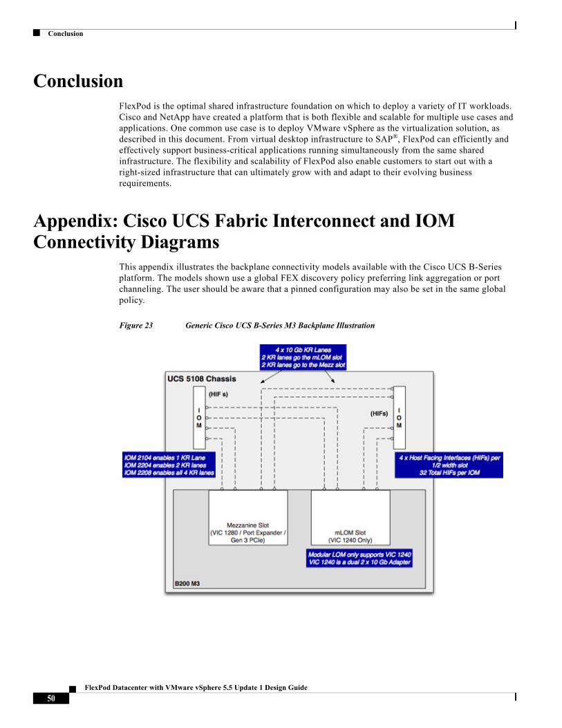
Conclusion
ConclusionFlexPod is the optimal shared infrastructure foundation on which to deploy a variety of IT workloads. Cisco and NetApp have created a platform that is both flexible and scalable for multiple use cases and applications. One common use case is to deploy VMware vSphere as the virtualization solution, as described in this document. From virtual desktop infrastructure to SAP®, FlexPod can efficiently and effectively support business-critical applications running simultaneously from the same shared infrastructure. The flexibility and scalability of FlexPod also enable customers to start out with a right-sized infrastructure that can ultimately grow with and adapt to their evolving business requirements.
Appendix: Cisco UCS Fabric Interconnect and IOM Connectivity Diagrams
This appendix illustrates the backplane connectivity models available with the Cisco UCS B-Series platform. The models shown use a global FEX discovery policy preferring link aggregation or port channeling. The user should be aware that a pinned configuration may also be set in the same global policy.
Figure 23 Generic Cisco UCS B-Series M3 Backplane Illustration
50FlexPod Datacenter with VMware vSphere 5.5 Update 1 Design Guide

Appendix: Cisco UCS Fabric Interconnect and IOM Connectivity Diagrams
Figure 24 M3 Connectivity Illustration with Fabric Extender model 2104 and VIC 1240
Figure 25 M3 Connectivity Illustration with Fabric Extender model 2204 and VIC 1240
51FlexPod Datacenter with VMware vSphere 5.5 Update 1 Design Guide

Appendix: Cisco UCS Fabric Interconnect and IOM Connectivity Diagrams
Figure 26 M3 Connectivity Illustration with Fabric Extender Model 2204, VIC 1240 and Port Expander
Figure 27 M3 Connectivity Illustration with Fabric Extender Model 2204, VIC 1240 and VIC 1280
52FlexPod Datacenter with VMware vSphere 5.5 Update 1 Design Guide

Appendix: Cisco UCS Fabric Interconnect and IOM Connectivity Diagrams
Figure 28 M3 Connectivity Illustration with Fabric Extender model 2208 and VIC 1240
Figure 29 M3 Connectivity Illustration with Fabric Extender model 2208, VIC 1240 and Port Expander
53FlexPod Datacenter with VMware vSphere 5.5 Update 1 Design Guide

References
Figure 30 M3 Connectivity Illustration with Fabric Extender model 2208, VIC 1240 and VIC 1280
ReferencesCisco Unified Computing System:http://www.cisco.com/en/US/products/ps10265/index.htmlCisco UCS 6200 Series Fabric Interconnects:
http://www.cisco.com/en/US/products/ps11544/index.html
Cisco UCS 5100 Series Blade Server Chassis:http://www.cisco.com/en/US/products/ps10279/index.htmlCisco UCS B-Series Blade Servers:http://www.cisco.com/en/US/partner/products/ps10280/index.htmlCisco UCS Adapters:http://www.cisco.com/en/US/products/ps10277/prod_module_series_home.htmlCisco UCS Manager:http://www.cisco.com/en/US/products/ps10281/index.html
54FlexPod Datacenter with VMware vSphere 5.5 Update 1 Design Guide

References
Cisco Nexus 5000 Series Switches:
http://www.cisco.com/en/US/products/ps9670/index.html
Cisco Nexus 1000v:http://www.cisco.com/en/US/products/ps9902/index.htmlCisco Prime Data Center Manager:
http://www.cisco.com/en/US/products/ps9369/index.html
VMware vCenter Server:
http://www.vmware.com/products/vcenter-server/overview.html
VMware vSphere:http://www.vmware.com/products/datacenter-virtualization/vsphere/index.htmlInteroperability Matrixes
VMware and Cisco Unified Computing System:
http://www.vmware.com/resources/compatibility
55FlexPod Datacenter with VMware vSphere 5.5 Update 1 Design Guide